WO2014119464A1 - Working vehicle - Google Patents
Working vehicle Download PDFInfo
- Publication number
- WO2014119464A1 WO2014119464A1 PCT/JP2014/051390 JP2014051390W WO2014119464A1 WO 2014119464 A1 WO2014119464 A1 WO 2014119464A1 JP 2014051390 W JP2014051390 W JP 2014051390W WO 2014119464 A1 WO2014119464 A1 WO 2014119464A1
- Authority
- WO
- WIPO (PCT)
- Prior art keywords
- stop
- angle
- stop position
- adjusted
- work
- Prior art date
Links
Images


Classifications
-
- E—FIXED CONSTRUCTIONS
- E02—HYDRAULIC ENGINEERING; FOUNDATIONS; SOIL SHIFTING
- E02F—DREDGING; SOIL-SHIFTING
- E02F9/00—Component parts of dredgers or soil-shifting machines, not restricted to one of the kinds covered by groups E02F3/00 - E02F7/00
- E02F9/20—Drives; Control devices
- E02F9/2025—Particular purposes of control systems not otherwise provided for
- E02F9/2033—Limiting the movement of frames or implements, e.g. to avoid collision between implements and the cabin
-
- E—FIXED CONSTRUCTIONS
- E02—HYDRAULIC ENGINEERING; FOUNDATIONS; SOIL SHIFTING
- E02F—DREDGING; SOIL-SHIFTING
- E02F3/00—Dredgers; Soil-shifting machines
- E02F3/04—Dredgers; Soil-shifting machines mechanically-driven
- E02F3/28—Dredgers; Soil-shifting machines mechanically-driven with digging tools mounted on a dipper- or bucket-arm, i.e. there is either one arm or a pair of arms, e.g. dippers, buckets
- E02F3/36—Component parts
- E02F3/42—Drives for dippers, buckets, dipper-arms or bucket-arms
- E02F3/43—Control of dipper or bucket position; Control of sequence of drive operations
- E02F3/435—Control of dipper or bucket position; Control of sequence of drive operations for dipper-arms, backhoes or the like
- E02F3/438—Memorising movements for repetition, e.g. play-back capability
-
- E—FIXED CONSTRUCTIONS
- E02—HYDRAULIC ENGINEERING; FOUNDATIONS; SOIL SHIFTING
- E02F—DREDGING; SOIL-SHIFTING
- E02F9/00—Component parts of dredgers or soil-shifting machines, not restricted to one of the kinds covered by groups E02F3/00 - E02F7/00
- E02F9/26—Indicating devices
- E02F9/264—Sensors and their calibration for indicating the position of the work tool
- E02F9/265—Sensors and their calibration for indicating the position of the work tool with follow-up actions (e.g. control signals sent to actuate the work tool)
Definitions
- the present invention relates to a work vehicle. More specifically, the present invention relates to a technique for limiting the movable range of the work device.
- a work vehicle such as a backhoe is configured to operate a control lever device to cause a work device provided in the work vehicle to perform a desired operation or work.
- various attachments such as a bucket attached to the tip of the work device may interfere with a turning device or an object within a movable range. Therefore, a work vehicle is known that can limit the movable range of the work device to an arbitrary range for each operation of the operation lever device. For example, it is like patent document 1.
- Patent Document 1 when the bucket is replaced with a breaker, the arm is actually moved to the side of the take-up side, and the state where the breaker is considerably close to the boom cylinder is revealed.
- the arm scooping movement stops at a set angle away from the arm extension side rather than the approached state, and control is performed so that the arm does not move further to the boom side. Is done.
- the work vehicle having such a configuration has a problem in that the work becomes complicated and the work efficiency may be lowered in order to cope with various attachments.
- the present invention has been made to solve such a problem. Even when a plurality of attachments are replaced, interference can be avoided and a reduction in work efficiency associated with the replacement of attachments can be reduced. An object is to provide a working device.
- a work machine main body a work device that is connected to the work machine main body and has a plurality of joints, and an attachment is detachably attached to the tip, and a work device for avoiding interference between the work devices.
- a work vehicle comprising: a control device in which a stop position to be stopped is set, wherein the control device has detection means for detecting the position of the work device, a plurality of the stop positions set in advance, and a plurality of The input means for independently adjusting the stop positions and the selection means for selecting a plurality of the stop positions are connected.
- an adjustment range is defined for each of the plurality of stop positions, and the adjustment ranges do not include values of the other stop positions.
- the input means adjusts the stop position by numerical input.
- the input means adjusts the stop position by direct teach that moves the work device to the stop position and stores the position.
- At least a part of the input means is detachably connected to the control device.
- the detecting means detects an angle of the joint of the working device.
- the plurality of stop positions can be adjusted independently, and the adjusted stop position does not affect other stop positions. Therefore, it is necessary to readjust when the attachment is replaced. Therefore, interference can be avoided and a reduction in work efficiency can be reduced.
- the value of the adjustment range of the stop position does not include a stop position other than the stop position to be adjusted. Don't get confused when choosing a value.
- the stop position can be adjusted without moving the work device, and the adjustment operation can be easily performed.
- the adjustment operation can be easily performed.
- the stop position adjustment by direct teach exceeds the adjustment range, the stop position is not adjusted, so the relationship between the stop position values in the selection means is not reversed, and multiple stop position values can be selected. There will be no confusion when you do.
- the stop position cannot be inadvertently adjusted, and the work device can be operated safely.
- the stop position can be determined only by detecting the angle of the work device, the control configuration can be simplified.
- FIG. 1 is a side view showing an overall configuration of a work vehicle according to an embodiment of the present invention. It is a side view which shows the stop position in a working device. It is a block diagram which shows the structure of stop control.
- A It is a figure which shows the adjustment selection screen displayed on a display part.
- B It is a figure which shows the adjustment screen displayed on a display part.
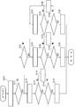
- It is a flowchart which shows adjustment of the stop position in an input means.
- a backhoe 1 that is a work vehicle according to an embodiment of the present invention will be described with reference to FIGS. 1 to 3.
- the backhoe 1 is described as an embodiment of the work vehicle.
- the work vehicle is not limited to this, and may be other agricultural vehicles, construction vehicles, industrial vehicles, or the like.
- the arrow F direction in the figure is defined as the front direction of the backhoe 1, and the front-rear and left-right directions in the state of entering the backhoe 1 and facing the front direction are defined as the front-rear left-right direction.
- the backhoe 1 mainly includes a traveling device 2, a turning device 3, and a work device 4.
- the traveling device 2 mainly includes a pair of left and right crawlers 5 and 5.
- the traveling device 2 can move the backhoe 1 forward and backward and turn by driving the left and right crawlers 5 and 5 of the aircraft.
- the swivel device 3 is a work machine main body and mainly includes a swivel base 6, a control unit 8, and an engine 9.
- the swivel base 6 is a main structure of the swivel device 3.
- the swivel base 6 is disposed above the travel device 2 and is supported by the travel device 2 so as to be capable of swiveling.
- the turning device 3 can turn the turntable 6 with respect to the traveling device 2 by driving a turning motor (not shown).
- a control unit 8 including various operation tools, an engine 9 serving as a power source, and the like are arranged on the swivel base 6, on the swivel base 6, a control unit 8 including various operation tools, an engine 9 serving as a power source, and the like are arranged.
- the working device 4 mainly includes a boom 10, an arm 11, a bucket 12 that is a kind of attachment, a boom cylinder 13, an arm cylinder 14, and an attachment cylinder 15.
- the boom 10 is rotatably supported at one end by a boom fulcrum 10a which is a joint at the front of the swivel base 6.
- the boom 10 is rotated around a boom fulcrum 10a as a rotation center by a boom cylinder 13 which is driven to extend and retract. More specifically, when the boom cylinder 13 is extended, the boom 10 is rotated upward, and when the boom cylinder 13 is contracted, the boom 10 is rotated downward.
- One end of the arm 11 is rotatably supported by the other end of the boom 10 by an arm fulcrum 11a which is a joint.
- the arm 11 is rotated around an arm fulcrum 11a at one end by an arm cylinder 14 that is driven to extend and retract. More specifically, when the arm cylinder 14 is extended, the arm 11 is rotated downward (the direction in which the other end of the arm 11 is close to the boom 10), and when the arm cylinder 14 is contracted, the arm 11 is upward ( The other end side of the arm 11 is rotated in a direction away from the boom 10.
- a position sensor 11 b that detects the rotational position of the arm 11 is provided in the support portion of the arm 11.
- the detection means detects the rotational position of the arm 11 as the position sensor 11b.
- the present invention is not limited to this, and the expansion / contraction amount of the arm cylinder 14 may be detected.
- the position sensor 11b which is a detection means is provided only in the arm fulcrum 11a, it is not limited, and more detailed information can be obtained by installing position sensors (angle detection sensors) at the boom fulcrum 10a and the attachment fulcrum 12a. It is good also as a structure which grasps
- the bucket 12 which is a kind of attachment is rotatably supported at one end by the other end of the arm 11 by an attachment fulcrum 12a which is a joint.
- the bucket 12 is rotated around an attachment fulcrum 12a at one end by an attachment cylinder 15 that is driven to extend and retract. More specifically, when the attachment cylinder 15 is extended, the bucket 12 is rotated downward (the direction in which the other end side of the bucket 12 is close to the arm 11), and when the attachment cylinder 15 is contracted, the bucket 12 Is rotated upward (the direction in which the other end side of the bucket 12 is separated from the arm 11).
- the work device 4 has a multi-joint structure that excavates earth and sand using the bucket 12.
- the backhoe 1 which concerns on this embodiment is set as the working apparatus 4 which has the bucket 12 and performs excavation work, it is not limited to this, For example, it is a working apparatus which has a hydraulic breaker and performs crushing work. There may be.
- the control unit 8 is provided with a cockpit 20 at substantially the center, and a right operation lever device 21 and a left operation lever device 22 are arranged on the left and right sides thereof.
- Each operation lever device is configured to be able to operate the turning motor, the boom cylinder 13, the arm cylinder 14, and the attachment cylinder 15.
- a display device 23 is provided on one side of the cockpit 20 (right side in the present embodiment). The display device 23 is arranged so that the display portion faces the pilot seated on the cockpit 20.
- stop positions SA, SB, and SC that are set to avoid interference with the work device 4 will be described.
- the stop positions SA, SB, and SC in the present embodiment are the upper arm portion 10b and the arm 11 of the boom 10 when the boom fulcrum 10a and the attachment fulcrum 12a are connected by the horizontal line H1. It is defined by the angle between That is, the stop positions SA, SB, and SC are positions where the movement of the arm 11 is stopped when the arm 11 moving toward the take-up side reaches the stop angle A, B, or C with respect to the boom 10. .
- the stop angle is positive in the counterclockwise direction and negative in the clockwise direction.
- a plurality of stop angles A, B, and C are set to correspond to various attachments.
- the interference of the work device 4 is prevented. Try to prevent.
- the stop positions SA, SB, and SC are a first stop position SA that is the take-in side, a second stop position SB that is the center side, and a third stop position SC that is the extension side, in order from the turning device 3.
- the first stop angle A is a set value corresponding to the first stop position SA
- the second stop angle B is a set value corresponding to the second stop position SB
- the set value is corresponding to the third stop position SC.
- the third stop angle C is set.
- the minimum stop angle X which is a numerical value corresponding to the position SX when the arm 11 is closest to the boom 10
- the maximum is a numerical value corresponding to the position SY where the arm 11 is farthest from the boom 10.
- a stop angle Y is preset.
- Stop positions SA, SB and SC can be adjusted independently.
- the adjustment range of the stop positions SA, SB, and SC does not include the values of the other stop positions SA, SB, and SC. That is, a range in which setting and adjustment can be performed is determined in advance for each of the stop positions SA, SB, and SC, and the adjustable range of the new first stop angle A1 at the first stop position SA is X ⁇ A1 ⁇ X1. It becomes.
- the adjustable range of the new second stop angle B1 at the second stop position SB is X1 ⁇ B1 ⁇ X2.
- the adjustable range of the new third stop angle C1 at the third stop position SC is X2 ⁇ C1 ⁇ Y.
- the stop angle used for the adjustable range has a relationship of X ⁇ X1 ⁇ X2 ⁇ Y.
- the control device 28 controls the LED display unit 25 and the liquid crystal display unit 26 by operating the screen operation unit 27.
- the control device 28 is configured inside the frame body 24 (see FIG. 6) adjacent to the LED display unit 25 and the liquid crystal display unit 26 or integrally with the ECU 16.
- the ECU 16 controls the engine 9, a hydraulic pump (not shown), and the like.
- the ECU 16 stores various programs for controlling the engine 9, the hydraulic pump, and the like. Further, the ECU 16 can perform predetermined calculations according to these programs and the like, and can store the results of the calculations.
- the ECU 16 may actually have a configuration in which a CPU, a ROM, a RAM, an HDD, and the like are connected by a bus, or may be configured by a one-chip LSI or the like.
- the ECU 16 is connected to various sensors (not shown) and a fuel injection device provided in the engine 9 and can control the engine 9.
- the ECU 16 is connected to the control device 28 of the display device 23, transmits control signals for warning / error information, fuel remaining amount, coolant temperature, etc. to the control device 28, and receives input signals input to the control device 28. It is possible to obtain.
- control device 28 sets the position sensor 11b as detection means and stop angles A, B, and C corresponding to a plurality (three) of stop positions SA, SB, and SC in advance, and these are independently set.
- the input means 51 for adjustment and the screen operation unit 27, which is a selection means for selecting a plurality of stop positions SA, SB, and SC, are connected.
- the input means 51 is a personal computer or the like provided separately from the display device 23, and is detachably connected to the control device 28 in the display device 23. By operating this input means 51, the aforementioned stop positions SA, SB, and SC can be adjusted.
- this embodiment is set as the structure which provides the input means 51 separately, it is not limited, It is good also as what incorporates an input means in the display apparatus 23, and adjusts stop position SA * SB * SC.
- the adjustment selection screen 53 shown in FIG. 4A is displayed on the display unit 52 of the input means 51 when adjusting the stop positions SA, SB, and SC.
- an arm limit stop adjustment angle (SC) item 54, an arm limit stop adjustment angle (SB) item 55, and an arm limit stop adjustment angle (SA) item 56 are displayed.
- the pilot displays an adjustment screen 57 on the display unit 52 by selecting an item to be adjusted among the above-described items 54, 55, and 56.
- the adjustment screen 57 shown in FIG. 4B is a screen displayed when the arm limit stop adjustment angle (SA) item 56 is selected, and adjusts the first stop angle A of the first stop position SA. It is a screen.
- 61 is a current value before adjustment (first stop angle A)
- 62 is a maximum adjustable value X1 (strictly less than X1)
- 63 is a new set value (adjusted first value).
- the minimum value X that can be adjusted is displayed at one stop angle A1), 64.
- Units of numerical values displayed in the items 61, 62, 63, and 64 are represented by angles.
- An adjustment button group 65 is provided on the right side of the new set value item 63.
- the adjustment button group 65 can adjust the new first stop angle A1 displayed in the item 63 of the new set value.
- the adjustment button group 65 has hundreds, tens, and ones, and a button for increasing the value and a button for decreasing the value, respectively.
- Below the adjustment button group 65 there is provided a slide bar 66 that can adjust the first stop angle A1 displayed in the new set value item 63 by sliding.
- a set button 67 for storing the adjusted first stop angle A1 of the new setting value item 63
- a cancel button 68 for canceling the adjustment halfway. .
- the input means 51 is connected to the control device 28 on the backhoe 1 side and is activated to adjust the stop angles A, B, and C corresponding to the stop positions SA, SB, and SC.
- step S10 of the flowchart showing the adjustment of the stop positions SA, SB, and SC in the input means 51 shown in FIG. 5 the input means 51 receives the stop positions SA and SB currently set from the control device 28 of the backhoe 1. ⁇ SC information is acquired and the adjustment selection screen 53 (see FIG. 4) is displayed, and one of the three stop position items 54, 55, and 56 displayed on the adjustment selection screen 53 is selected by the operator. Then, the process proceeds from step S10 to step S11.
- step S11 the input means 51 determines whether or not the first stop position SA (item 56) has been selected. As a result, when it is determined that the first stop position SA has been selected, the input unit 51 proceeds from step S11 to step S12. On the other hand, when it is determined that the first stop position SA is not selected, that is, when it is determined that the second stop position SB or the third stop position SC is selected, the input unit 51 proceeds from step S11 to step S21. .
- step S12 the input means 51 displays the adjustment screen 57 shown in FIG.
- the input means 51 displays on the adjustment screen 57 the maximum value B and minimum value X of the range in which the first stop position SA can be adjusted, the first stop angle A that is the currently set current value, and the set value to be adjusted. A1 is displayed. Then, the user operates the adjustment button group 65 or the slide bar 66 to adjust the first stop angle A to the new first stop angle A1.
- step S13 the input means 51 determines whether or not the user has pressed the set button 67 after finishing the adjustment of the new first stop angle A1 of the first stop position SA. As a result, when it is determined that the set button 67 has been pressed, the input unit 51 proceeds from step S13 to step S14. On the other hand, if it is determined that the set button 67 has not been pressed, the input means 51 proceeds from step S13 to step S12 again.
- step S14 the input unit 51 determines whether or not the adjusted first stop angle A1 is within the adjustable range. That is, the input means 51 determines whether or not “the stop angle X when the arm 11 is closest to the turning device 3 ⁇ the adjusted first stop angle A1 ⁇ the preset stop angle X1”. As a result, when it is determined that the adjusted first stop angle A1 is within the adjustable range, the input unit 51 proceeds from step S14 to step S15. On the other hand, when it is determined that the adjusted first stop angle A1 is outside the adjustable range, the input unit 51 proceeds from step S14 to step S16. In step S16, after displaying that the adjusted first stop angle A1 cannot be adjusted (changed) (error display), the input unit 51 proceeds from step S16 to step S12 again.
- step S15 the input means 51 transmits the adjusted first stop angle A1 as a new first stop angle A to the storage unit 29 of the control device 28 of the backhoe 1 and completes.
- the transferred new first stop angle A1 is updated in the storage unit 29 in the control device 28 by ending and restarting the backhoe 1.
- step S11 If it is determined in step S11 that the first stop position SA is not selected, that is, it is determined that the second stop position SB or the third stop position SC is selected, the input means 51 that has moved to step S21 It is determined whether or not the stop position SB (item 55) has been selected. As a result, when it is determined that the second stop position SB has been selected, the input unit 51 proceeds from step S21 to step S22. On the other hand, when it is determined that the second stop position SB is not selected, that is, when it is determined that the third stop position SC is selected, the input unit 51 proceeds from step S21 to step S32.
- step 22 the input unit 51 displays the adjustment screen 57 for the second stop position SB.
- the input means 51 adjusts the second stop angle B, which is the current value currently set in the item 61 of the adjustment screen 57, the maximum value X2 that can adjust the second stop position SB in the item 62, and the item 63.
- the set value (second stop angle B1) and the minimum value X1 at which the second stop position SB can be adjusted are displayed in the item 64.
- the user adjusts the second stop angle B to a new second stop angle B1 by operating the adjustment button group 65 or the slide bar 66 (first stop position SA shown in FIG. 4B). (See figure at
- step S23 the input unit 51 determines whether or not the user has pressed the set button 67 after completing the adjustment of the new second stop angle B1 of the second stop position SB. As a result, when it is determined that the set button 67 has been pressed, the input unit 51 proceeds from step S23 to step S24. On the other hand, if it is determined that the set button 67 has not been pressed, the input means 51 proceeds from step S23 to step S22 again.
- step S24 the input means 51 determines whether or not the adjusted second stop angle B1 is within the adjustable range. In other words, the input unit 51 determines whether or not “the preset stop angle X1 ⁇ the adjusted second stop angle B1 ⁇ the preset stop angle X2”.
- the adjusted second stop angle B1 is not less than the preset stop angle X1 or larger than the preset stop angle X2, so that the relationship between the values of the stop positions SA, SB, and SC is satisfied. There is no reverse rotation, and confusion due to the reverse rotation of the magnitude when selecting a plurality of stop position values is prevented.
- the input unit 51 proceeds from step S24 to step S25.
- step S24 when it is determined that the adjusted second stop angle B1 is outside the adjustable range, the input unit 51 proceeds from step S24 to step S26.
- step S26 after displaying that the adjusted second stop angle B1 cannot be adjusted (changed) (error display), the input unit 51 proceeds from step S26 to step S22 again.
- step S25 the input means 51 transmits the adjusted second stop angle B1 as a new second stop angle B to the storage unit 29 of the control device 28 of the backhoe 1 and completes.
- the input unit 51 displays the adjustment screen 57 for the third stop position SC.
- the input means 51 adjusts the third stop angle C, which is the current value currently set in the item 61 of the adjustment screen 57, the maximum value Y that the third stop position SC can be adjusted in the item 62, and the item 63.
- the set value (third stop angle C1 to be adjusted) and the minimum stop angle X2 at which the third stop position SC can be adjusted are displayed in the item 64.
- the user operates the adjustment button group 65 or the slide bar 66 to adjust the third stop angle C to the new third stop angle C1 (first stop position SA shown in FIG. 4B). (See figure at
- step S33 the input means 51 determines whether or not the user has pressed the set button 67 after completing the adjustment of the new set value C1 of the third stop position SC. As a result, when it is determined that the set button 67 has been pressed, the input unit 51 proceeds from step S33 to step S34. On the other hand, if it is determined that the set button 67 has not been pressed, the input means 51 proceeds from step S33 to step S32 again.
- step S34 the input means 51 determines whether or not the adjusted third stop angle C1 is within the adjustable range. In other words, the input means 51 determines whether or not “the preset stop angle X2 ⁇ the adjusted third stop angle C1 ⁇ the stop angle Y at which the arm 11 is farthest from the boom 10”.
- the third stop angle C1 is not less than or equal to the preset stop angle X2, so that the relationship between the values of the stop positions SB and SC is not reversed, and a plurality of stop position values are selected. Prevents confusion caused by reversing the size.
- the input unit 51 proceeds from step S34 to step S35.
- step S34 when it is determined that the adjusted third stop angle C1 is outside the adjustable range, the input unit 51 proceeds from step S34 to step S36.
- step S36 after displaying that the adjusted third stop angle C1 cannot be adjusted (changed) (error display), the input means 51 proceeds from step S36 to step S32 again.
- step S35 the input means 51 transmits the adjusted third stop angle C1 to the storage unit 29 of the control device 28 of the backhoe 1 as the new third stop angle C, and is completed.
- the configuration of the display device 23 that is an operation tool for applying the stop positions SA, SB, and SC will be specifically described.
- the display device 23 includes a frame 24, an LED display unit 25, a liquid crystal display unit 26, a screen operation unit 27, and a control device 28.
- the frame body 24 is formed in a box shape that is substantially L-shaped in side view and includes a long side portion and a short side portion.
- the frame body 24 is disposed on the right side of the cockpit 20 so that one side surface of the short side portion faces the cockpit 20 (see FIG. 1).
- the LED display unit 25 is provided above one side surface of the short side portion of the frame body 24.
- the LED display unit 25 displays a plurality of graphics representing the operating state of the backhoe 1, the presence / absence of a warning, and the like, and an LED is arranged on each graphic.
- the LED display unit 25 lights only a specific figure when a corresponding LED is turned on under a predetermined condition. In this way, the LED display unit 25 is configured to be able to transmit information to the operator.
- the LED display unit 25 displays the LED by turning on the LED.
- the present invention is not limited to this, and any light source that can be turned on may be used.
- the liquid crystal display unit 26 as a display unit is provided on one side of the short side portion of the frame body 24 and below the LED display unit 25.
- the liquid crystal display unit 26 includes a liquid crystal screen that displays information.
- the liquid crystal display unit 26 can check the operating state of the backhoe 1 by switching the liquid crystal screen to a display corresponding to each work mode by operating a screen operation unit 27 described later. In this manner, the liquid crystal display unit 26 is configured to be able to transmit information to the operator.
- the liquid crystal display unit 26 is displayed on a liquid crystal screen, but is not limited to this, and may be any display that can arbitrarily display a plurality of information.
- the screen operation unit 27 is disposed on one side surface of the short side portion of the frame body 24 and below the liquid crystal display unit 26.
- the screen operation unit 27 includes a menu button and a plurality of operation buttons F1 button, F2 button, F3 button, and F4 button.
- the screen operation unit 27 is configured to be able to select a screen displayed on the liquid crystal display unit 26 by operating the menu button, F1 button, F2 button, F3 button, and F4 button.
- the control device 28 controls the LED display unit 25 and the liquid crystal display unit 26.
- the control device 28 is configured inside the frame body 24 adjacent to the LED display unit 25 and the liquid crystal display unit 26 or integrally with the ECU 16.
- the movable range restriction mode screen 33 shown in FIG. 7 is displayed.
- step S101 displays the movable range restriction mode screen 33, and the stop position (any one of SA, SB, SC) previously selected from the storage unit 29.
- the latest stop angles A, B, and C corresponding to the stop positions SA, SB, and SC, and the arm angle that is the current angle of the arm 11 is acquired from the position sensor 11b. If the previously selected stop position does not exist, the default stop position is acquired.
- the operator (setting person) selects either “ON” 33a or “SET” 33b on the movable range restriction mode screen 33 and operates the F4 button which is a decision button (see FIG. 7). Then, the control apparatus 28 transfers to step S102 from step S101.
- step S102 the control device 28 determines whether or not “ON” 33a is selected. As a result, if it is determined that “ON” 33a has been selected, the control device 28 proceeds from step S102 to step S103. On the other hand, when “ON” 33a is not selected, that is, when “SET” 33b is selected, the control device 28 proceeds from step S102 to step S104.
- step S103 the control device 28 displays the restricted position mode transition screen 32 shown in FIG. 9 for a predetermined time, and proceeds from step S103 to step S105.
- step S105 the control device 28 displays the excavation mode screen 31 in which the stop position control ON mark 100 shown in FIG. 10 is lit, ends the control for selecting the stop positions SA, SB, and SC, and interferes with the work device 4.
- the control for avoiding the problem is executed.
- step S104 the control device 28 displays a restricted position SET mode screen 34 shown in FIG.
- the restriction position SET mode screen 34 displays the current arm position 34d acquired in step S102 and the previously set stop position.
- the operator moves the white triangle mark 34e using F2 and F3 of the screen operation unit 27, and selects appropriate stop position marks 34a, 34b, and 34c.
- F4 for determining the adjusted stop position marks 34a, 34b, and 34c is operated by the operator, the control device 28 proceeds from step S104 to step S103.
- the stop position mark 34a shown in FIG. 11 corresponds to the first stop position SA
- the stop position mark 34b corresponds to the second stop position SB
- the stop position mark 34c corresponds to the third stop position SC.
- the input means 51 may actually be configured to move the work device 4 to a desired stop position, store the position (angle), and adjust the stop position. Moreover, it is good also as a structure used together with adjustment of the stop angle by the adjustment button group 65 or the slide bar 66 shown in FIG. In other words, the user operates the operation levers 21 and 22 to adjust the stop position of the arm 11 while visually observing, and the position sensor 11b converts the stop position into a numerical value as a stop angle. This is reflected in the adjusted first stop angle A1 displayed.
- the first stop angle A1 obtained by actually moving the arm 11 is set to the first stop angle A1, and in step S14 shown in FIG. It is determined whether or not the first stop angle A1 digitized by moving 11 is within an adjustable range. That is, the input unit 51 determines that the minimum stop angle X set in advance is equal to or less than the first stop angle A1 that is obtained by numerically moving the arm 11 and is set in advance.
- stop positions SA, SB, and SC that are set to avoid the interference of the work device 4 in another embodiment will be described.
- description is abbreviate
- the set angles of the stop positions SA, SB, and SC in the above embodiment could be changed within a preset adjustment range.
- the adjustment range corresponding to the stop positions SA, SB, and SC varies according to the setting change of the stop positions SA, SB, and SC.
- the adjustable range of the new first stop angle A1 at the first stop position SA is X ⁇ A1 ⁇ B.
- the adjustable range of the new second stop angle B1 at the second stop position SB is A ⁇ B1 ⁇ C.
- the adjustable range of the new third stop angle C1 at the third stop position SC is B ⁇ C1 ⁇ Y.
- the input means 51 is connected to the control device 28 on the backhoe 1 side and is activated to adjust the stop angles A, B, and C corresponding to the stop positions SA, SB, and SC.
- step S110 of the flowchart showing the adjustment of the stop positions SA, SB, and SC in the input means 51 shown in FIG. 12 the input means 51 receives the stop positions SA and SB currently set from the control device 28 of the backhoe 1. ⁇ SC information is acquired and the adjustment selection screen 53 (see FIG. 4) is displayed, and one of the three stop position items 54, 55, and 56 displayed on the adjustment selection screen 53 is selected by the operator. Then, the process proceeds from step S110 to step S111.
- step S111 the input means 51 determines whether or not the first stop position SA (item 56) has been selected. As a result, when it is determined that the first stop position SA has been selected, the input unit 51 proceeds from step S111 to step S112. On the other hand, when it is determined that the first stop position SA is not selected, that is, when it is determined that the second stop position SB or the third stop position SC is selected, the input unit 51 proceeds from step S111 to step S121. .
- step S112 the input means 51 displays the adjustment screen 57 shown in FIG. At this time, the input means 51 displays on the adjustment screen 57 the maximum value B and minimum value X of the range in which the first stop position SA can be adjusted, the first stop angle A that is the currently set current value, and the set value to be adjusted. A1 is displayed. Then, the user operates the adjustment button group 65 or the slide bar 66 to adjust the first stop angle A to the new first stop angle A1.
- step S113 the input unit 51 determines whether or not the user has pressed the set button 67 after completing the adjustment of the new first stop angle A1 of the first stop position SA. As a result, when it is determined that the set button 67 has been pressed, the input unit 51 proceeds from step S113 to step S114. On the other hand, if it is determined that the set button 67 has not been pressed, the input means 51 proceeds from step S113 to step S112 again.
- step S114 the input unit 51 determines whether or not the adjusted first stop angle A1 is within the adjustable range. That is, the input means 51 determines whether or not “the stop angle X when the arm 11 is closest to the turning device 3 ⁇ the adjusted first stop angle A1 ⁇ the second stop angle B”. As a result, when it is determined that the adjusted first stop angle A1 is within the adjustable range, the input unit 51 proceeds from step S114 to step S115. On the other hand, when it is determined that the adjusted first stop angle A1 is outside the adjustable range, the input unit 51 proceeds from step S114 to step S116. In step S116, after displaying that the adjusted first stop angle A1 cannot be adjusted (changed) (error display), the input means 51 proceeds from step S116 to step S12 again.
- step S115 the input means 51 transmits the adjusted first stop angle A1 as a new first stop angle A to the storage unit 29 of the control device 28 of the backhoe 1, and the process is completed.
- the transferred new first stop angle A1 is updated in the storage unit 29 in the control device 28 by ending and restarting the backhoe 1.
- the input means 51 determines whether or not the adjusted second stop angle B1 is within the adjustable range. To do. That is, the input means 51 determines whether or not “the first stop angle A at the first stop position SA ⁇ the adjusted second stop angle B1 ⁇ the third stop angle C at the third stop position SC”.
- the adjusted second stop angle B1 is not less than the first stop angle A or greater than the third stop angle C, so that the relationship between the values of the stop positions SA, SB, and SC is reversed. This prevents the confusion caused by the reverse of the magnitude when selecting a plurality of stop position values.
- step S124 when it is determined that the adjusted second stop angle B1 is within the adjustable range, the input unit 51 proceeds from step S124 to step S125.
- step S124 when it is determined that the adjusted second stop angle B1 is outside the adjustable range, the input unit 51 proceeds from step S124 to step S126.
- step S126 after displaying that the adjusted second stop angle B1 cannot be adjusted (changed) (error display), the input means 51 proceeds from step S126 to step S122 again.
- the input means 51 determines whether or not the adjusted third stop angle C1 is within the adjustable range. To do. That is, the input means 51 determines whether or not “the second stop angle B at the second stop position SB ⁇ the adjusted third stop angle C1 ⁇ the stop angle Y at which the arm 11 is farthest away from the boom 10”. Judging.
- the third stop angle C1 is not less than or equal to the second stop position B, so that the relationship between the values of the stop positions SB and SC does not reverse, and the magnitude of the third stop angle C1 is large when selecting a plurality of stop position values. Prevents confusion caused by reversing.
- step S134 when it is determined that the adjusted third stop angle C1 is within the adjustable range, the input unit 51 proceeds from step S134 to step S135. On the other hand, if it is determined that the adjusted third stop angle C1 is outside the adjustable range, the input unit 51 proceeds from step S134 to step S136. In step S136, after displaying that the adjusted third stop angle C1 cannot be adjusted (changed) (error display), the input unit 51 proceeds from step S136 to step S132 again.
- the swivel device 3 that is a work implement main body, and the boom fulcrum 10a, the arm fulcrum 11a, and the attachment fulcrum 12a that are connected to the work implement main body and that are a plurality of joints, are attached to the tip in a detachable manner.
- a work vehicle (backhoe 1) including a work device 4 and a control device 28 in which stop positions SA, SB, and SC for stopping the work device 4 are set to avoid interference with the work device 4.
- a position sensor 11b which is a detecting means for detecting the position of the work device 4, and a plurality of the stop positions SA, SB, BC are set in advance, and a plurality of the stop positions SA, SB, SC are set.
- the screen operation unit 27 which is a selection means for selecting the plurality of stop positions SA, SB, and SC.
- the plurality of stop positions SA, SB, and SC can be adjusted independently, and the adjusted stop position does not affect other stop positions, so the attachment 12 is replaced.
- the attachment 12 is replaced.
- the plurality of stop positions SA, SB, and SC each have an adjustment range that does not include the values of the other stop positions SA, SB, and SC.
- the adjustment range values of the stop positions SA, SB, and SC do not include stop positions other than the stop position to be adjusted.
- the relationship between the values of SB and SC is not reversed, and there is no confusion when selecting the values A, B, and C of the plurality of stop positions SA, SB, and SC.
- the input means 51 adjusts the stop positions SA, SB, and SC by numerical input.
- the stop positions SA, SB, and SC can be adjusted without moving the work device 4, and the adjustment operation can be easily performed.
- the input means 51 adjusts the stop positions SA, SB, and SC by direct teaching that moves the work device 4 to the stop positions SA, SB, and SC and stores the positions.
- the stop positions SA, SB, and SC can be visually confirmed when adjusting the stop positions SA, SB, and SC, so that the adjustment operation can be easily performed. Further, when the adjustment of the stop positions SA, SB, and SC by direct teaching is out of the adjustment range, the stop position is not adjusted. Therefore, the values of the stop positions SA, SB, and SC in the screen operation unit 27 serving as selection means ( The relationship between the stop angles A, B, and C) is not reversed, and there is no confusion when selecting the values A, B, and C of the plurality of stop positions SA, SB, and SC.
- At least a part of the input means 51 is detachably connected to the control device 28.
- the position sensor 11b as the detection means detects the angle of the arm fulcrum 11a which is the joint of the work device 4.
- the present invention can be used in a technique for limiting the movable range of a work device in a work vehicle.
Landscapes
- Engineering & Computer Science (AREA)
- Mining & Mineral Resources (AREA)
- Civil Engineering (AREA)
- General Engineering & Computer Science (AREA)
- Structural Engineering (AREA)
- Mechanical Engineering (AREA)
- Operation Control Of Excavators (AREA)
- Component Parts Of Construction Machinery (AREA)
Abstract
Description
その結果、第一停止位置SAが選択されたと判断した場合、入力手段51はステップS11からステップS12へと移行する。
他方、第一停止位置SAが選択されていないと判断した場合、つまり第二停止位置SB又は第三停止位置SCが選択されたと判断した場合、入力手段51はステップS11からステップS21へと移行する。 In step S11, the input means 51 determines whether or not the first stop position SA (item 56) has been selected.
As a result, when it is determined that the first stop position SA has been selected, the
On the other hand, when it is determined that the first stop position SA is not selected, that is, when it is determined that the second stop position SB or the third stop position SC is selected, the
その結果、セットボタン67が押されたと判断した場合、入力手段51は、ステップS13からステップS14に移行する。
他方、セットボタン67が押されていないと判断した場合、入力手段51は、ステップS13から再びステップS12へと移行する。 In step S13, the input means 51 determines whether or not the user has pressed the
As a result, when it is determined that the
On the other hand, if it is determined that the
その結果、調整した第一停止角度A1が調整可能範囲内であると判断した場合、入力手段51は、ステップS14からステップS15へと移行する。
他方、調整した第一停止角度A1が調整可能範囲外であると判断した場合、入力手段51は、ステップS14からステップS16へと移行する。ステップS16において、調整した第一停止角度A1が調整(変更)できない旨の表示(エラー表示)をしたのち、入力手段51は、ステップS16から再びステップS12へと移行する。 In step S14, the
As a result, when it is determined that the adjusted first stop angle A1 is within the adjustable range, the
On the other hand, when it is determined that the adjusted first stop angle A1 is outside the adjustable range, the
その結果、第二停止位置SBが選択されたと判断した場合、入力手段51はステップS21からステップS22へと移行する。
他方、第二停止位置SBが選択されていないと判断した場合、つまり第三停止位置SCが選択されたと判断した場合、入力手段51はステップS21からステップS32へと移行する。 If it is determined in step S11 that the first stop position SA is not selected, that is, it is determined that the second stop position SB or the third stop position SC is selected, the input means 51 that has moved to step S21 It is determined whether or not the stop position SB (item 55) has been selected.
As a result, when it is determined that the second stop position SB has been selected, the
On the other hand, when it is determined that the second stop position SB is not selected, that is, when it is determined that the third stop position SC is selected, the
このとき、入力手段51は、調整画面57の項目61に現在設定されている現在値である第二停止角度B、項目62に第二停止位置SBが調整できる最大値X2、項目63に調整する設定値(第二停止角度B1)、項目64に第二停止位置SBが調整できる最小値X1を表示する。そして、ユーザーは、調整ボタン群65又はスライドバー66を操作することで、第二停止角度Bを新たな第二停止角度B1へと調整する(図4の(b)に示す第一停止位置SAにおける図を参照)。 In
At this time, the input means 51 adjusts the second stop angle B, which is the current value currently set in the
その結果、セットボタン67が押されたと判断した場合、入力手段51は、ステップS23からステップS24に移行する。
他方、セットボタン67が押されていないと判断した場合、入力手段51は、ステップS23から再びステップS22へと移行する。 In step S23, the
As a result, when it is determined that the
On the other hand, if it is determined that the
その結果、調整した第二停止角度B1が調整可能範囲内であると判断した場合、入力手段51は、ステップS24からステップS25へと移行する。
他方、調整した第二停止角度B1が調整可能範囲外であると判断した場合、入力手段51は、ステップS24からステップS26へと移行する。ステップS26において、調整した第二停止角度B1が調整(変更)できない旨の表示(エラー表示)をしたのち、入力手段51は、ステップS26から再びステップS22へと移行する。 In step S24, the input means 51 determines whether or not the adjusted second stop angle B1 is within the adjustable range. In other words, the
As a result, when it is determined that the adjusted second stop angle B1 is within the adjustable range, the
On the other hand, when it is determined that the adjusted second stop angle B1 is outside the adjustable range, the
このとき、入力手段51は、調整画面57の項目61に現在設定されている現在値である第三停止角度C、項目62に第三停止位置SCが調整できる最大値Y、項目63に調整する設定値(調整する第三停止角度C1)、項目64に第三停止位置SCが調整できる最小の停止角度X2を表示する。そして、ユーザーは、調整ボタン群65又はスライドバー66を操作することで、第三停止角度Cを新たな第三停止角度C1へと調整する(図4の(b)に示す第一停止位置SAにおける図を参照)。 On the other hand, when the process proceeds from step S21 to step S32, the
At this time, the input means 51 adjusts the third stop angle C, which is the current value currently set in the
その結果、セットボタン67が押されたと判断した場合、入力手段51は、ステップS33からステップS34に移行する。
他方、セットボタン67が押されていないと判断した場合、入力手段51は、ステップS33から再びステップS32へと移行する。 In step S33, the input means 51 determines whether or not the user has pressed the
As a result, when it is determined that the
On the other hand, if it is determined that the
その結果、調整した第三停止角度C1が調整可能範囲内であると判断した場合、入力手段51は、ステップS34からステップS35へと移行する。
他方、調整した第三停止角度C1が調整可能範囲外であると判断した場合、入力手段51は、ステップS34からステップS36へと移行する。ステップS36において、調整した第三停止角度C1が調整(変更)できない旨の表示(エラー表示)をしたのち、入力手段51は、ステップS36から再びステップS32へと移行する。 In step S34, the input means 51 determines whether or not the adjusted third stop angle C1 is within the adjustable range. In other words, the input means 51 determines whether or not “the preset stop angle X2 ≦ the adjusted third stop angle C1 ≦ the stop angle Y at which the
As a result, when it is determined that the adjusted third stop angle C1 is within the adjustable range, the
On the other hand, when it is determined that the adjusted third stop angle C1 is outside the adjustable range, the
その結果、「ON」33aが選択されたと判断した場合、制御装置28は、ステップS102からステップS103へと移行する。
他方、「ON」33aが選択されていない場合、つまり、「SET」33bが選択された場合、制御装置28は、ステップS102からステップS104へと移行する。 In step S102, the
As a result, if it is determined that “ON” 33a has been selected, the
On the other hand, when “ON” 33a is not selected, that is, when “SET” 33b is selected, the
なお、同じ構成に関しては説明を省略し、上記の実施形態と同じ符号を用いて説明する。 Next, stop positions SA, SB, and SC that are set to avoid the interference of the
In addition, description is abbreviate | omitted about the same structure and it demonstrates using the same code | symbol as said embodiment.
その結果、第一停止位置SAが選択されたと判断した場合、入力手段51はステップS111からステップS112へと移行する。
他方、第一停止位置SAが選択されていないと判断した場合、つまり第二停止位置SB又は第三停止位置SCが選択されたと判断した場合、入力手段51はステップS111からステップS121へと移行する。 In step S111, the input means 51 determines whether or not the first stop position SA (item 56) has been selected.
As a result, when it is determined that the first stop position SA has been selected, the
On the other hand, when it is determined that the first stop position SA is not selected, that is, when it is determined that the second stop position SB or the third stop position SC is selected, the
その結果、セットボタン67が押されたと判断した場合、入力手段51は、ステップS113からステップS114に移行する。
他方、セットボタン67が押されていないと判断した場合、入力手段51は、ステップS113から再びステップS112へと移行する。 In step S113, the
As a result, when it is determined that the
On the other hand, if it is determined that the
その結果、調整した第一停止角度A1が調整可能範囲内であると判断した場合、入力手段51は、ステップS114からステップS115へと移行する。
他方、調整した第一停止角度A1が調整可能範囲外であると判断した場合、入力手段51は、ステップS114からステップS116へと移行する。ステップS116において、調整した第一停止角度A1が調整(変更)できない旨の表示(エラー表示)をしたのち、入力手段51は、ステップS116から再びステップS12へと移行する。 In step S114, the
As a result, when it is determined that the adjusted first stop angle A1 is within the adjustable range, the
On the other hand, when it is determined that the adjusted first stop angle A1 is outside the adjustable range, the
その結果、調整した第二停止角度B1が調整可能範囲内であると判断した場合、入力手段51は、ステップS124からステップS125へと移行する。
他方、調整した第二停止角度B1が調整可能範囲外であると判断した場合、入力手段51は、ステップS124からステップS126へと移行する。ステップS126において、調整した第二停止角度B1が調整(変更)できない旨の表示(エラー表示)をしたのち、入力手段51は、ステップS126から再びステップS122へと移行する。 Similarly, when it is determined by the input means 51 that the second stop position SB has been selected, in step S124, the input means 51 determines whether or not the adjusted second stop angle B1 is within the adjustable range. To do. That is, the input means 51 determines whether or not “the first stop angle A at the first stop position SA <the adjusted second stop angle B1 <the third stop angle C at the third stop position SC”. Here, the adjusted second stop angle B1 is not less than the first stop angle A or greater than the third stop angle C, so that the relationship between the values of the stop positions SA, SB, and SC is reversed. This prevents the confusion caused by the reverse of the magnitude when selecting a plurality of stop position values.
As a result, when it is determined that the adjusted second stop angle B1 is within the adjustable range, the
On the other hand, when it is determined that the adjusted second stop angle B1 is outside the adjustable range, the
その結果、調整した第三停止角度C1が調整可能範囲内であると判断した場合、入力手段51は、ステップS134からステップS135へと移行する。
他方、調整した第三停止角度C1が調整可能範囲外であると判断した場合、入力手段51は、ステップS134からステップS136へと移行する。ステップS136において、調整した第三停止角度C1が調整(変更)できない旨の表示(エラー表示)をしたのち、入力手段51は、ステップS136から再びステップS132へと移行する。 Similarly, when it is determined by the input means 51 that the third stop position SC has been selected, in step S134, the input means 51 determines whether or not the adjusted third stop angle C1 is within the adjustable range. To do. That is, the input means 51 determines whether or not “the second stop angle B at the second stop position SB <the adjusted third stop angle C1 ≦ the stop angle Y at which the
As a result, when it is determined that the adjusted third stop angle C1 is within the adjustable range, the
On the other hand, if it is determined that the adjusted third stop angle C1 is outside the adjustable range, the
3 旋回装置(作業機本体)
4 作業装置
10a ブーム支点
11a アーム支点
11b 位置センサー
12 アタッチメント
12a アタッチメント支点
27 画面操作部
28 制御装置
51 入力手段
A 第一停止角度
B 第二停止角度
C 第三停止角度
SA 第一停止位置
SB 第二停止位置
SC 第三停止位置 1 Backhoe (work vehicle)
3 swivel device (work machine body)
4 Working
Claims (6)
- 作業機本体と、当該作業機本体に接続され複数個の関節を有し先端にアタッチメントが着脱可能に装着される作業装置と、
前記作業装置の干渉を回避するため作業装置を停止させる停止位置が設定される制御装置と、を具備する作業車両であって、
前記制御装置には、
前記作業装置の位置を検知する検知手段と、
予め複数の前記停止位置を設定し、複数の前記停止位置をそれぞれ独立して調整する入力手段と、
複数の前記停止位置を選択する選択手段と、が接続される作業車両。 A work machine main body, a work device connected to the work machine main body, having a plurality of joints, and having an attachment detachably attached to the tip;
A work vehicle comprising: a control device in which a stop position for stopping the work device in order to avoid interference of the work device is set;
In the control device,
Detecting means for detecting the position of the working device;
An input unit that sets a plurality of the stop positions in advance and independently adjusts the plurality of stop positions;
A work vehicle to which a plurality of selection means for selecting the stop positions are connected. - 複数の前記停止位置は、互いに他の前記停止位置の値を含まない調整範囲がそれぞれ定められている請求項1に記載の作業車両。 2. The work vehicle according to claim 1, wherein the plurality of stop positions each have an adjustment range that does not include values of the other stop positions.
- 前記入力手段は、数値入力により前記停止位置の調整をおこなう請求項1又は請求項2に記載の作業車両。 The work vehicle according to claim 1 or 2, wherein the input means adjusts the stop position by numerical input.
- 前記入力手段は、前記作業装置を停止位置に移動させその位置を記憶するダイレクトティーチによって停止位置の調整をおこなう請求項1から請求項3のいずれか一項に記載の作業車両。 The work vehicle according to any one of claims 1 to 3, wherein the input means adjusts the stop position by direct teaching that moves the work device to a stop position and stores the position.
- 前記入力手段の少なくとも一部は、前記制御装置と着脱可能に接続される請求項1から請求項4のいずれか一項に記載の作業車両。 The work vehicle according to any one of claims 1 to 4, wherein at least a part of the input means is detachably connected to the control device.
- 前記検知手段は前記作業装置の前記関節の角度を検知する請求項1から請求項5のいずれか一項に記載の作業車両。 The work vehicle according to any one of claims 1 to 5, wherein the detection means detects an angle of the joint of the work device.
Priority Applications (4)
| Application Number | Priority Date | Filing Date | Title |
|---|---|---|---|
| US14/765,112 US9580886B2 (en) | 2013-01-31 | 2014-01-23 | Working vehicle |
| EP14746810.2A EP2952635B1 (en) | 2013-01-31 | 2014-01-23 | Working vehicle |
| CN201480007069.5A CN105209692B (en) | 2013-01-31 | 2014-01-23 | Working vehicle |
| KR1020157023465A KR101763374B1 (en) | 2013-01-31 | 2014-01-23 | Working vehicle |
Applications Claiming Priority (2)
| Application Number | Priority Date | Filing Date | Title |
|---|---|---|---|
| JP2013017347A JP6101498B2 (en) | 2013-01-31 | 2013-01-31 | Work vehicle |
| JP2013-017347 | 2013-01-31 |
Publications (1)
| Publication Number | Publication Date |
|---|---|
| WO2014119464A1 true WO2014119464A1 (en) | 2014-08-07 |
Family
ID=51262178
Family Applications (1)
| Application Number | Title | Priority Date | Filing Date |
|---|---|---|---|
| PCT/JP2014/051390 WO2014119464A1 (en) | 2013-01-31 | 2014-01-23 | Working vehicle |
Country Status (6)
| Country | Link |
|---|---|
| US (1) | US9580886B2 (en) |
| EP (1) | EP2952635B1 (en) |
| JP (1) | JP6101498B2 (en) |
| KR (1) | KR101763374B1 (en) |
| CN (1) | CN105209692B (en) |
| WO (1) | WO2014119464A1 (en) |
Cited By (1)
| Publication number | Priority date | Publication date | Assignee | Title |
|---|---|---|---|---|
| US10801180B2 (en) | 2018-06-11 | 2020-10-13 | Deere & Company | Work machine self protection system |
Families Citing this family (7)
| Publication number | Priority date | Publication date | Assignee | Title |
|---|---|---|---|---|
| GB2531762A (en) * | 2014-10-29 | 2016-05-04 | Bamford Excavators Ltd | Working machine |
| JP6665412B2 (en) * | 2015-03-23 | 2020-03-13 | 株式会社タダノ | Work machine adjustment devices |
| JP6697361B2 (en) * | 2016-09-21 | 2020-05-20 | 川崎重工業株式会社 | Hydraulic excavator drive system |
| EP3521517B1 (en) * | 2016-09-30 | 2021-04-07 | Sumitomo (S.H.I.) Construction Machinery Co., Ltd. | Excavator |
| US11053661B2 (en) * | 2017-03-29 | 2021-07-06 | Hitachi Construction Machinery Co., Ltd. | Work machine |
| JP2019127725A (en) * | 2018-01-23 | 2019-08-01 | 株式会社クボタ | Work machine, control method of work machine, program, and storage medium for the same |
| FI130526B (en) * | 2020-05-14 | 2023-11-02 | Ponsse Oyj | Arrangement and method for controlling at least one operation of a work machine, and work machine |
Citations (4)
| Publication number | Priority date | Publication date | Assignee | Title |
|---|---|---|---|---|
| JPS63122829A (en) * | 1986-11-10 | 1988-05-26 | Kubota Ltd | Slewing type working vehicle |
| JPH09256405A (en) * | 1996-03-21 | 1997-09-30 | Hitachi Constr Mach Co Ltd | Interference prevention device for construction machine |
| JPH108490A (en) | 1996-06-26 | 1998-01-13 | Hitachi Constr Mach Co Ltd | Front control device of construction machine and area setting method |
| JP2006028908A (en) * | 2004-07-16 | 2006-02-02 | Shin Caterpillar Mitsubishi Ltd | Work machine |
Family Cites Families (10)
| Publication number | Priority date | Publication date | Assignee | Title |
|---|---|---|---|---|
| JPH06256405A (en) * | 1993-03-05 | 1994-09-13 | Japan Synthetic Rubber Co Ltd | Method for coagulating polymer latex |
| JP3679848B2 (en) * | 1995-12-27 | 2005-08-03 | 日立建機株式会社 | Construction machine working range restriction control device |
| US5957989A (en) | 1996-01-22 | 1999-09-28 | Hitachi Construction Machinery Co. Ltd. | Interference preventing system for construction machine |
| US6169948B1 (en) | 1996-06-26 | 2001-01-02 | Hitachi Construction Machinery Co., Ltd. | Front control system, area setting method and control panel for construction machine |
| JP3633746B2 (en) | 1997-04-10 | 2005-03-30 | 日立建機株式会社 | Automatic driving excavator |
| DE69811894T2 (en) * | 1997-07-09 | 2004-02-12 | Crown Equipment Corp., New Bremen | PERFORMANCE DATA MONITOR |
| JP2010105569A (en) * | 2008-10-30 | 2010-05-13 | Sumitomo (Shi) Construction Machinery Co Ltd | Monitoring screen attachment device of construction machinery |
| EP2370644A4 (en) * | 2008-11-26 | 2014-03-05 | Volvo Constr Equip Ab | Method for calibrating an angle sensor and vehicle with an angle sensor |
| JP5048169B2 (en) * | 2010-03-15 | 2012-10-17 | 株式会社小松製作所 | Control device and control method for construction machine working machine |
| DE102010048662A1 (en) * | 2010-10-07 | 2012-04-12 | Jungheinrich Aktiengesellschaft | Truck with a height-adjustable load carrier |
-
2013
- 2013-01-31 JP JP2013017347A patent/JP6101498B2/en active Active
-
2014
- 2014-01-23 KR KR1020157023465A patent/KR101763374B1/en active IP Right Grant
- 2014-01-23 WO PCT/JP2014/051390 patent/WO2014119464A1/en active Application Filing
- 2014-01-23 CN CN201480007069.5A patent/CN105209692B/en not_active Expired - Fee Related
- 2014-01-23 EP EP14746810.2A patent/EP2952635B1/en active Active
- 2014-01-23 US US14/765,112 patent/US9580886B2/en active Active
Patent Citations (4)
| Publication number | Priority date | Publication date | Assignee | Title |
|---|---|---|---|---|
| JPS63122829A (en) * | 1986-11-10 | 1988-05-26 | Kubota Ltd | Slewing type working vehicle |
| JPH09256405A (en) * | 1996-03-21 | 1997-09-30 | Hitachi Constr Mach Co Ltd | Interference prevention device for construction machine |
| JPH108490A (en) | 1996-06-26 | 1998-01-13 | Hitachi Constr Mach Co Ltd | Front control device of construction machine and area setting method |
| JP2006028908A (en) * | 2004-07-16 | 2006-02-02 | Shin Caterpillar Mitsubishi Ltd | Work machine |
Cited By (1)
| Publication number | Priority date | Publication date | Assignee | Title |
|---|---|---|---|---|
| US10801180B2 (en) | 2018-06-11 | 2020-10-13 | Deere & Company | Work machine self protection system |
Also Published As
| Publication number | Publication date |
|---|---|
| EP2952635B1 (en) | 2019-07-31 |
| CN105209692B (en) | 2017-05-10 |
| US20150368876A1 (en) | 2015-12-24 |
| US9580886B2 (en) | 2017-02-28 |
| JP6101498B2 (en) | 2017-03-22 |
| EP2952635A4 (en) | 2016-09-21 |
| EP2952635A1 (en) | 2015-12-09 |
| JP2014148806A (en) | 2014-08-21 |
| KR20150110801A (en) | 2015-10-02 |
| KR101763374B1 (en) | 2017-07-31 |
| CN105209692A (en) | 2015-12-30 |
Similar Documents
| Publication | Publication Date | Title |
|---|---|---|
| JP6101498B2 (en) | Work vehicle | |
| JP6072993B1 (en) | Work vehicle control system, control method, and work vehicle | |
| KR100230828B1 (en) | Front control system, area setting method and control panel for construction machine | |
| US9670939B2 (en) | Operation control system | |
| EP3214229B1 (en) | Work vehicle | |
| JP6957081B2 (en) | Work machine | |
| EP3604684B1 (en) | Work machinery | |
| EP3561182A1 (en) | Work machine | |
| JP2009228249A (en) | Interference prevention device for working machine | |
| WO2012056993A1 (en) | Work vehicle | |
| JP2017186875A (en) | Control system of work vehicle, control method, and work vehicle | |
| JP2017186875A5 (en) | ||
| KR100656036B1 (en) | Construction machinery | |
| JP6559529B2 (en) | Construction machinery | |
| WO2022210488A1 (en) | Work machine display control system, work machine display system, work machine, work machine display control method, and work machine display control program | |
| JP5781971B2 (en) | Work vehicle | |
| JP7307522B2 (en) | SENSOR AUTOMATIC IDENTIFICATION SYSTEM AND IDENTIFICATION METHOD IN CONSTRUCTION MACHINERY | |
| KR102008021B1 (en) | Monitor control method using joystick | |
| JP7324703B2 (en) | construction machinery | |
| WO2020203314A1 (en) | Work machine calibration method, work machine controller, and work machine | |
| KR101877059B1 (en) | Control apparatus in a construction machine | |
| JPH11247217A (en) | Working machine control device for construction machine | |
| JPH11247220A (en) | Work machine controller of construction machinery | |
| JP2019116733A (en) | Working machine | |
| JP2018017091A (en) | Construction machine |
Legal Events
| Date | Code | Title | Description |
|---|---|---|---|
| 121 | Ep: the epo has been informed by wipo that ep was designated in this application |
Ref document number: 14746810 Country of ref document: EP Kind code of ref document: A1 |
|
| DPE1 | Request for preliminary examination filed after expiration of 19th month from priority date (pct application filed from 20040101) | ||
| NENP | Non-entry into the national phase |
Ref country code: DE |
|
| WWE | Wipo information: entry into national phase |
Ref document number: 14765112 Country of ref document: US |
|
| WWE | Wipo information: entry into national phase |
Ref document number: 2014746810 Country of ref document: EP |
|
| ENP | Entry into the national phase |
Ref document number: 20157023465 Country of ref document: KR Kind code of ref document: A |