WO2014115462A1 - スピーカー用グリル、スピーカー装置及び音響機器 - Google Patents
スピーカー用グリル、スピーカー装置及び音響機器 Download PDFInfo
- Publication number
- WO2014115462A1 WO2014115462A1 PCT/JP2013/084360 JP2013084360W WO2014115462A1 WO 2014115462 A1 WO2014115462 A1 WO 2014115462A1 JP 2013084360 W JP2013084360 W JP 2013084360W WO 2014115462 A1 WO2014115462 A1 WO 2014115462A1
- Authority
- WO
- WIPO (PCT)
- Prior art keywords
- covering material
- speaker
- grill
- frame
- housing
- Prior art date
- Legal status (The legal status is an assumption and is not a legal conclusion. Google has not performed a legal analysis and makes no representation as to the accuracy of the status listed.)
- Ceased
Links
Images





Classifications
-
- H—ELECTRICITY
- H04—ELECTRIC COMMUNICATION TECHNIQUE
- H04R—LOUDSPEAKERS, MICROPHONES, GRAMOPHONE PICK-UPS OR LIKE ACOUSTIC ELECTROMECHANICAL TRANSDUCERS; ELECTRIC HEARING AIDS; PUBLIC ADDRESS SYSTEMS
- H04R1/00—Details of transducers, loudspeakers or microphones
- H04R1/02—Casings; Cabinets ; Supports therefor; Mountings therein
- H04R1/023—Screens for loudspeakers
Definitions
- the present invention relates to a grill disposed on the front surface of a speaker, and also relates to a speaker device and an audio device including the grill.
- a speaker grille is mounted on the front surface of a speaker housed in a housing (see, for example, Patent Document 1 and Patent Document 2).
- the speaker grill of Patent Document 1 is configured by stretching a cloth-like covering material called a mesh-shaped saran net (jersey net) on a grill frame.
- the speaker grill of Patent Document 2 is configured by mounting a metal plate-like covering material such as punching metal on the grill frame.
- An object of the present invention is to provide a speaker grille to which both a cloth-like covering material and a metal plate-like covering material can be attached, and a speaker device and an acoustic device including the same.
- the speaker grill according to the present invention includes: A speaker grille that is attached to the front of the housing containing the speakers, A resin grille frame having an outer frame constituting the outer periphery; A covering material covering the front surface of the grill frame, The grill frame includes a first covering material mounting recess that is recessed so as to go around the front side of the outer frame, and a second covering material mounting recess that is recessed so as to go around the back side of the outer frame.
- the speaker grill of the present invention it is possible to select and install either a plate-like covering material or a cloth-like covering material as a covering material on the grill frame, so that the grill frame can be shared. Can be achieved.
- a plate-like covering material and a cloth-like covering material can be selected and attached to the grill frame, design variations of the speaker grill can be diversified, and the design of the speaker device and the audio equipment can be improved.
- FIG. 1 is a perspective view of an audio device to which the present invention is applied.
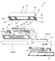
- FIG. 2 is an exploded perspective view of an audio device to which the present invention is applied.
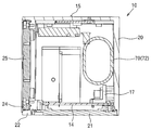
- FIG. 3 is a cross-sectional view taken along the line AA in FIG. 1, and is a cross-sectional view with the speaker grille removed.
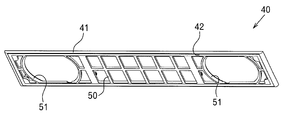
- FIG. 4 is a perspective view of the grill frame as viewed obliquely from the front.
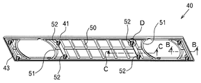
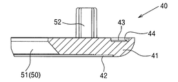
- FIG. 5 is a perspective view of the grill frame as viewed obliquely from the rear. 6 is an enlarged cross-sectional view taken along the line BB in FIG.
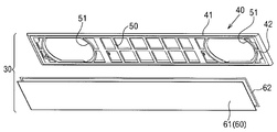
- FIG. 7 is an exploded perspective view of a speaker grill that employs a plate-shaped covering material as a covering material.
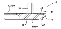
- FIG. 8 is an enlarged cross-sectional view showing a state in which the plate-like covering material is adhered to the first covering material attaching recess.
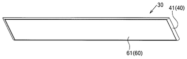
- FIG. 9 is a perspective view of a speaker grill that employs a plate-shaped covering material.
- FIG. 10 is an exploded perspective view of a speaker grill that employs a cloth-like covering material as a covering material.
- FIG. 11 is an enlarged cross-sectional view showing a state in which the cloth-like covering material is thermocompression bonded to the second covering material attaching recess.
- FIG. 12 is a perspective view of a speaker grill that employs a cloth-like covering material.
- 13 is a cross-sectional view taken along line CC in FIG.
- FIG. 14 is a perspective view of the circle D in FIG.
- FIG. 15 is a perspective view of the bass reflex duct.
- 16 is a cross-sectional view taken along line EE of FIG.
- FIG. 17 is a right side view of the bass reflex duct.
- 18 is a cross-sectional view taken along line FF in FIG.
- the present invention records information such as music, video and images input from a personal computer, hard disk, TV, etc., and information such as music, video and images input via a network etc. in an internal memory.
- An embodiment applied to the so-called “sound bar”, which is a so-called “sound bar” that outputs audio from the built-in speakers 12 and 12 and can be displayed on a display means such as an externally connected television or personal computer display will be described.
- the present invention is not limited to a sound bar, and can of course be applied to a speaker device or other audio equipment including the configuration of the present invention.
- FIG. 1 is a perspective view of an audio device 10 according to an embodiment of the present invention. As shown in FIG. 1, it can be configured in a horizontally long shape. In the figure, the front side (front side in FIG. 1) of the acoustic device 10 has a shape that is enlarged in the width direction as compared to the back side.
- FIG. 2 is an exploded perspective view of the acoustic device 10.
- the acoustic device 10 can be configured by housing main components in a housing 20 made of an integrally molded product of resin. As shown in FIGS. 1 and 2, the housing 20 has a horizontally long shape, and the front side is enlarged in the width direction as compared with the back side.
- a power display unit (LED) 15 and a volume operation unit 16 are provided on the upper surface of the housing 20.
- the volume operation unit 16 can be a touch panel type operation unit, and can be adjusted by touching the vicinity of the volume operation unit 16.
- the housing 20 has an open bottom surface and is closed by a bottom plate 21 on the bottom surface.
- the bottom plate 21 can be attached to the housing 20 by screwing or the like.
- the front surface of the housing 20 has a front wall 22 in which speaker holes 23 into which the speakers 12 are fitted are opened on the left and right.
- the front wall 22 may have a lattice shape, and an opening 24 is formed between the speaker holes 23, 23.
- the opening 24 is closed by an auxiliary front wall 25 having the same rectangular shape as the opening 24.
- a bass reflex duct opening 27 through which a later-described bass reflex duct 70 protrudes is formed on one side surface of the housing 20.
- Reference numeral 71 in FIG. 2 is an annular decorative plate that covers the outer periphery of the front end of the bass reflex duct 70.
- the housing 20 accommodates speakers 12 and 12, a bass reflex duct 70, and a substrate 14 on which electronic components are mounted.
- the substrate 14 can be attached to the bottom plate 21.
- the board 14 has electronic parts such as tuners and amplifiers for outputting audio from the speakers 12 and 12, a terminal box 17 having terminals for connection to a commercial power source and external connection, and input video and audio.
- Electronic components necessary for all operations, control, and the like related to the acoustic device 10 are mounted, such as a memory to be stored and a decoder that outputs input information to an output device such as a television or a personal computer.
- the terminal of the terminal box 17 is installed so that it may protrude on the back side of the housing 20.
- the bottom surface of the housing 20 is opened and the bottom surface of the housing 20 is closed by attaching the substrate 14 to the bottom plate 21, thereby providing the following advantages.
- the substrate 14 can be attached to the bottom plate 21 in advance, it is easier to assemble than when the front surface is opened and the substrate 14 is inserted into the housing 20 and fixed.
- the front surface of the housing 20 is opened and then closed separately with a panel, screwing bosses are provided on the top surface, side surface and / or bottom surface of the housing 20, and sound leakage from the outer periphery of the panel is prevented. It is necessary to provide a sealing groove or the like for prevention, but if the configuration is to attach the bottom plate 21, it is only necessary to provide a boss only on the side surface, the upper surface and the bottom surface of the housing 20 can be thinned, The acoustic device 10 can be reduced in thickness and improved in design. There is also an advantage that the number of parts can be reduced.
- a speaker grill 30 covering the front surface of the housing 20 is attached to the front surface of the housing 20.
- the speaker grill 30 includes a grill frame 40 and a covering material 60 that covers the front surface of the grill frame 40.
- FIG. 4 and 5 are perspective views of the grill frame 40.
- the grill frame 40 can be made of resin, and includes an outer frame 41 that forms an outer periphery.
- the outer frame 41 is suspended by one or a plurality of ribs 50 and 50.
- the outer frame 41 is formed with a first covering material mounting recess 42 that is recessed so as to go around the front side.
- the first covering material mounting recess 42 is desirably formed on the inner peripheral side of the outer frame 41 so as to be a stepped portion lower than the outer peripheral side.
- a plate-shaped covering material 61 having a large number of holes such as punching metal is mounted on the first covering material mounting recess 42 as shown in FIG.
- the plate-shaped covering material 61 can be made of metal or resin, and can be colored, letters, or designs as desired.
- the plate-shaped covering material 61 can be attached to the first covering material mounting recess 42 by a double-sided tape 62 or an adhesive.
- FIG. 9 is a perspective view of the speaker grill 30 in which the plate-like covering material 61 is mounted on the grill frame 40.
- the grill frame 40 leaves the outer periphery of the outer frame 41 and the front surface is covered with the plate-shaped covering material 61.
- the outer frame 41 is formed with a second covering material mounting recess 43 that is recessed so as to go around the back side.
- the second covering material mounting recess 43 can be formed with an interval from the outer periphery of the outer frame 41.
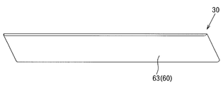
- a cloth-like covering material 63 such as a mesh-shaped saran net (jersey net) is attached to the second covering-material mounting recess 43 as shown in FIG.
- the cloth-like covering material 63 can be selected from various colors as desired, and can be provided with characters and patterns.
- the cloth-like covering material 63 covers from the front side of the grill frame 40, extends the peripheral edge to the back surface of the outer frame 41, and is thermocompression-bonded or adhered to the second covering material mounting recess 43. It is attached by.
- the bonding strength between the second covering material mounting recess 43 and the cloth-like covering material 63 can be increased by melting the protrusion 44 at the time of crimping, and the cloth-like covering material 63. Can be prevented from peeling.
- FIG. 12 is a perspective view of the speaker grill 30 in which the cloth-like covering material 63 is mounted on the grill frame 40.
- the grill frame 40 is in a state where the front surface and the outer periphery are all covered with the cloth-like covering material 63.
- the grill frame 40 can be shared by selecting and mounting either the plate-shaped coating material 61 or the cloth-shaped coating material 63 as the coating material 60 on the grill frame 40. Can be planned. Moreover, since the plate-shaped covering material 61 and the cloth-shaped covering material 63 can be selected and mounted on the grill frame 40 as desired, the design variations of the speaker grill 30 can be diversified, and the design of the acoustic device 10 can be improved. Can be increased.
- the rib 50 suspended between the outer frames 41 of the grill frame 40 is for preventing deformation and breakage of the covering material 60 when a finger or a foreign object hits the covering material 60.
- the rib 50 is configured such that the position facing the speakers 12, 12 is a punched hole 51 having a shape similar to that of the speaker 12, and the other portions of the rib 50 are rectangular or the like. It is desirable to have a lattice shape. By making the portions other than the positions facing the speakers 12 and 12 into a punched shape, it is possible to achieve a reduction in component costs and a reduction in the weight of the grill frame 40.
- the rib 50 has at least a cross-sectional shape on the back side as shown in FIG. As a result, it is possible to prevent the sound output from the speaker 12 from hitting the rib 50 and reflecting it, and to enhance acoustic effects such as the spread of sound output from the speaker 12 and sound omission.
- the rib 50 has a curved cross-sectional shape, and the curved portion does not need to be a perfect circle, but may be an elliptical shape. Moreover, it can also be set as the spindle shape where the back side of the rib 50 was pointed. Although the acoustic effect is slightly inferior, only the peripheral surface from the back surface to the side surface of the rib 50 may be curved, and a straight portion may remain on a part of the back surface of the rib 50.
- the speaker grill 30 having the above configuration is attached to the front surface of the housing 20.
- the speaker grill 30 can employ a frame mounting structure that is attached to the housing 20 by inserting a boss 52 projecting from the grill frame 40 into a fitting hole 26 formed in the housing 20.
- a fitting hole 26 is formed in the front wall 22 of the housing 20 and the auxiliary front wall 25 attached to the front wall 22.
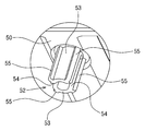
- FIG. 14 is an enlarged perspective view of the boss 52 projecting from the grill frame 40.
- the boss 52 has a cylindrical wall surface 53 protruding from the rear surface of the grill frame 40 toward the housing 20, and the cylindrical wall surface 53 faces in the protruding direction.
- One or a plurality of slits 54 are cut out.
- the boss 52 is provided with a reinforcing rib 55 projecting from one or a plurality of locations on the outer periphery of the cylindrical wall surface 53 and the back surface of the grill frame 40.
- the reinforcing rib 55 is desirably provided with a draft in a direction in which the outer periphery is reduced from the back side to the tip side of the grill frame 40.
- the shape of the boss 52 includes the cylindrical wall surface 53 having the slit 54 and the reinforcing rib 55 as described above, so that when the boss 52 is fitted into the fitting hole 26 of the housing 20, The outer peripheral surface hits the inner surface of the fitting hole 26, and the boss 52 enters the fitting hole 26 while bending the cylindrical wall surface 53 inward.
- the insertion resistance can be reduced as compared with the case of contact with the surface. Further, by providing a draft angle on the outer periphery of the reinforcing rib 55, even if the boss 52 or the fitting hole 26 has a size variation, the reinforcing rib 55 has a reduced diameter at the tip. 26 is easy to fit.
- the cylindrical wall surface 53 is provided with the slits 54, the cylindrical wall surface 53 can be provided with a spring property. Therefore, the cylindrical wall surface 53 is bent inward when the boss 52 is inserted, and the fitting hole 26 is surely fitted. The reinforcing rib 55 can be brought into contact.
- the boss 52 since the boss 52 has the above-described configuration, the speaker grill 30 can be easily attached to and detached from the housing 20, so that it is easy to maintain.
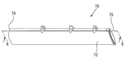
- FIG. 15 is a perspective view of the bass reflex duct 70 housed in the housing 20 as shown in FIG.
- the bass reflex duct 70 has a cylindrical portion 72 that communicates the inside of the housing 20 and the outside of the housing 20, and is disposed on the back side of the speakers 12, 12 to reduce the sound generated from the rear surfaces of the speakers 12, 12.
- the sound range is amplified by Helmholtz resonance and output to the outside.
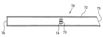
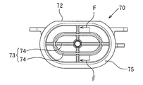
- a lattice frame 73 is provided in the cylindrical portion 72 of the bass reflex duct 70 as shown in FIG.
- the lattice frame 73 can be configured by connecting a plurality of housings 74, and at least the inside of the housing 20 has a cross-sectional curved shape as shown in FIGS.
- the casing 74 has a shape similar to the inner peripheral shape of the opening 75, so that further sound omission can be improved and wind noise can be reduced.
- the housing 74 has a spindle shape in which both the inner side and the outer side of the housing 20 are curved in cross section.
- the shape of the curved section of the casing 74 does not have to be a perfect circle, and may be an elliptical shape. Also, a spindle shape as shown in FIG. 18 may be used. With such a structure, the spindle shape has a better acoustic effect because the air flow is better than that of a perfect circle. In addition to the spindle type, the acoustic effect is slightly inferior, but only the peripheral surface from the back surface to the side surface of the housing 74 is curved, and a straight portion remains on a part of the back surface of the housing 74, or the length of the bass reflex duct 70 is long. It does not matter as a rectangular parallelepiped shape having long sides in the direction.
- the lattice frame 73 can be attached to the bass reflex duct 70 by inserting the lattice frame 73 from a notch (not shown) formed on the side surface of the bass reflex duct 70. Further, the bass reflex duct 70 may be divided in the longitudinal direction or the radial direction, and the lattice frame 73 may be sandwiched. Further, the bass reflex duct 70 may be divided in the longitudinal direction, and the lattice frame 73 may be integrally formed on one end face.
- the installation position of the lattice frame 73 is a position away from the opening 75 on the outside of the bass reflex duct 70, and the inner center of the bass reflex duct 70 in the longitudinal direction or substantially in the center. It is desirable to be close to the opening 76 on the side. This is because if the lattice frame 73 is installed in the vicinity of the opening 75 on the outer side of the bass reflex duct 70, since the air enters and exits heavily, a wind noise may be generated.
- the acoustic effect of the sound output from the bass reflex duct 70 can be enhanced as much as possible.
- the speaker grill 30 and the audio device 10 are not limited to the above-described and illustrated external shapes.
- the structure and function of the audio equipment 10 are not limited to the above.
- the present invention can be applied not only to the acoustic device 10 but also to a speaker device in which the acoustic device 10 includes a part of its configuration and functions.
- the present invention is useful as a speaker grille to which both a cloth-like covering material and a metal plate-like covering material can be attached, and a speaker device and an acoustic device including the grille.
Landscapes
- Physics & Mathematics (AREA)
- Engineering & Computer Science (AREA)
- Acoustics & Sound (AREA)
- Signal Processing (AREA)
- Details Of Audible-Bandwidth Transducers (AREA)
Abstract
布状被覆材と金属製の板状被覆材の何れも取り付けることのできるスピーカー用グリルと、これを具えたスピーカー装置及び音響機器を提供する。本発明に係るスピーカー用グリルは、スピーカーを収容した筺体前面に取り付けられるスピーカー用グリルあって、外周を構成する外フレームを有する樹脂製のグリルフレームと、該グリルフレームの前面を覆う被覆材と、を具え、前記グリルフレームは、前記外フレームの前面側を一周するよう凹設された第1の被覆材取付凹部と、前記外フレームの背面側を一周するよう凹設された第2の被覆材取付凹部と、を具える。
Description
本発明は、スピーカーの前面に配置されるグリルに関するものであり、また、これを具えたスピーカー装置及び音響機器に関するものである。
スピーカー装置やスピーカーを具えた音響機器においては、筺体内に収容されたスピーカーの前面にスピーカー用グリルを装着している(例えば、特許文献1、特許文献2参照)。
特許文献1のスピーカー用グリルは、グリルフレームにメッシュ状のサランネット(ジャージネット)と称される布状被覆材を張設して構成される。
特許文献2のスピーカー用グリルは、グリルフレームにパンチングメタル等の金属製の板状被覆材を装着して構成される。
スピーカー用グリルをスピーカーに取り付けることで、スピーカーの振動板を保護し、スピーカー装置や音響機器の内部に埃が入ることを防止することができる。
スピーカー装置や音響機器の意匠性を高め、ユーザの製品選択肢を増やすことが求められている。
しかしながら、布状被覆材を張設するグリルと、金属製の板状被覆材を装着するグリルは、夫々異なるグリルフレームを用いているため、部品点数が増加してしまうこととなる。
しかしながら、布状被覆材を張設するグリルと、金属製の板状被覆材を装着するグリルは、夫々異なるグリルフレームを用いているため、部品点数が増加してしまうこととなる。
本発明の目的は、布状被覆材と金属製の板状被覆材の何れも取り付けることのできるスピーカー用グリルと、これを具えたスピーカー装置及び音響機器を提供することである。
本発明に係るスピーカー用グリルは、
スピーカーを収容した筺体の前面に取り付けられるスピーカー用グリルであって、
外周を構成する外フレームを有する樹脂製のグリルフレームと、
該グリルフレームの前面を覆う被覆材と、を具え、
前記グリルフレームは、前記外フレームの前面側を一周するよう凹設された第1の被覆材取付凹部と、前記外フレームの背面側を一周するよう凹設された第2の被覆材取付凹部と、を具える。
スピーカーを収容した筺体の前面に取り付けられるスピーカー用グリルであって、
外周を構成する外フレームを有する樹脂製のグリルフレームと、
該グリルフレームの前面を覆う被覆材と、を具え、
前記グリルフレームは、前記外フレームの前面側を一周するよう凹設された第1の被覆材取付凹部と、前記外フレームの背面側を一周するよう凹設された第2の被覆材取付凹部と、を具える。
本発明に係るスピーカー用グリルによれば、グリルフレームに被覆材として、板状被覆材と布状被覆材の何れかを選択して装着することができるようにしたことで、グリルフレームの共通化を図ることができる。また、板状被覆材と布状被覆材を選択してグリルフレームに装着できるから、スピーカー用グリルのデザインバリエーションを多様化することができ、スピーカー装置や音響機器の意匠性を高めることができる。
以下、本発明をパソコン、ハードディスク、テレビなどからの入力された音楽、映像、画像などの情報や、ネットワークなどを経由して入力された音楽、映像、画像などの情報を内部メモリに記録したり、内蔵されたスピーカー12,12から音声出力、外部接続されたテレビやパソコンのディスプレイなどの表示手段に表示することのできる音響機器10、所謂「サウンドバー」に適用した実施形態について説明するが、本発明はサウンドバーに限定されるものではなく、本発明の構成を含むスピーカー装置やその他の音響機器に適用できることは勿論である。
図1は、本発明の一実施形態に係る音響機器10の斜視図である。図1に示すように、横長形状に構成することができる。図示では、音響機器10の前面側(図1の手前側)は、背面側に比して幅方向に拡大した形状である。
図2は、音響機器10の分解斜視図である。音響機器10は、主要な部品を樹脂の一体成型品からなる筺体20の内部に収容して構成することができる。筺体20は、図1及び図2に示すように、横長形状であり、背面側に比して前面側が幅方向に拡大している。
筺体20の上面には、電源表示部(LED)15と、音量操作部16を有する。音量操作部16は、周囲をタッチパネル式の操作部とすることができ、音量操作部16の近傍に触れることで音量調整を行なうことができる
筺体20は、図2及び図3に示すように、底面が開口しており、底面には底板21により閉じられる。底板21は、筺体20にネジ止め等により取り付けることができる。
筺体20の前面には、左右にスピーカー12が嵌まるスピーカー用孔23が開設された前壁22を有する。前壁22は格子状とすることができ、スピーカー用孔23,23間に開口24が形成されており、該開口24は、開口24の形状と同じ矩形の補助前壁25によって閉止される。スピーカー用孔23,23間に開口24を形成することで、上記した電源表示部15と音量操作部16の設置や後述する端子ボックス17の設置を開口24から行なうことができる。
また、筺体20の一方の側面には、後述するバスレフダクト70が臨出するバスレフダクト用開口27が開設されている。図2中符号71は、バスレフダクト70の先端外周をカバーする環状の化粧板である。
筺体20の内部には、スピーカー12,12、バスレフダクト70、電子部品の実装された基板14が収容される。基板14は、底板21に装着することができる。
基板14には、スピーカー12,12から音声出力を行なうためのチューナーやアンプ等の電子部品、商用電源への接続や外部接続のための端子を具える端子ボックス17、入力された映像や音声を記憶するメモリ、入力された情報をテレビやパソコンなどの出力デバイスに出力するデコーダ等、音響機器10に係るすべての動作、制御等に必要な電子部品が実装されている。なお、端子ボックス17の端子は、筺体20の背面側に臨出するよう設置される。
上記のように筺体20について、底面側を開口させ、基板14を底板21に取り付けることで筺体20の底面を塞ぐようにしたことで、以下の利点がある。
基板14を予め底板21に取り付けることができるから、前面を開口させて、基板14を筺体20に挿入して固定する場合に比して、組立てが容易である。
また、筺体20の前面を開口させて、後から別途パネルで閉じる場合に、ネジ止め用のボスを筺体20の上面、側面及び/又は底面に設け、さらには、パネルの外周からの音漏れを防止するための密閉用の溝等を設ける必要があるが、底板21を取り付ける構成であれば、側面のみにボスを設ければよいから、筺体20の上面及び底面を薄型化することができ、音響機器10の薄型化やデザイン性の向上を達成できる。また、部品点数を削減できる利点もある。
筺体20の前面には、図1及び図2に示すように、筺体20の前面を覆うスピーカー用グリル30が取り付けられる。スピーカー用グリル30は、グリルフレーム40と、該グリルフレーム40の前面を覆う被覆材60とを有している。
図4及び図5は、グリルフレーム40の斜視図である。グリルフレーム40は、樹脂製とすることができ、外周を構成する外フレーム41を具え、該外フレーム41間は、1又は複数のリブ50,50により懸架されている。
外フレーム41は、図4及び図6に示すように、前面側を一周するよう凹設された第1の被覆材取付凹部42が形成されている。該第1の被覆材取付凹部42は、外フレーム41の内周側に外周側に比べて低い段部となるよう形成することが望ましい。
前記第1の被覆材取付凹部42には、図7に示すように、被覆材60として、パンチングメタルの如き多数の孔を有する板状被覆材61が装着される。板状被覆材61は、金属製又は樹脂製とすることができ、所望に応じて着色や文字、図柄を付すことができる。
板状被覆材61は、図8に示すように、第1の被覆材取付凹部42に両面テープ62や接着などにより装着することができる。
図9は、グリルフレーム40に板状被覆材61を装着したスピーカー用グリル30の斜視図である。板状被覆材61をグリルフレーム40に装着することで、グリルフレーム40は、外フレーム41の外周を残し、前面は板状被覆材61に覆われた状態となる。
また、外フレーム41は、図5及び図6に示すように、背面側を一周するよう凹設された第2の被覆材取付凹部43が形成されている。該第2の被覆材取付凹部43は、外フレーム41の外周から間隔を存して形成することができる。
前記第2の被覆材取付凹部43には、図10に示すように、被覆材60として、メッシュ状のサランネット(ジャージネット)の如き布状被覆材63が装着される。布状被覆材63は、所望により種々の色から選択することができ、文字や模様を付すことができる。
布状被覆材63は、図11に示すように、グリルフレーム40の前面側から被せて、周縁を外フレーム41の背面まで延出させ、第2の被覆材取付凹部43に熱圧着や接着などにより装着される。
熱圧着により布状被覆材63を装着する場合、第2の被覆材取付凹部43の底面に、図6に示すように底面の他の部分よりも盛り上がった突条44を形成しておき、熱圧着の際に、突条44を溶融させることで、図11に示すように、第2の被覆材取付凹部43と布状被覆材63との接合強度を高めることができ、布状被覆材63の剥離を防ぐことができる。
図12は、グリルフレーム40に布状被覆材63を装着したスピーカー用グリル30の斜視図である。布状被覆材63をグリルフレーム40に装着することで、グリルフレーム40は、前面及び外周のすべてが布状被覆材63に覆われた状態となる。
上記のように、グリルフレーム40に被覆材60として、板状被覆材61と布状被覆材63の何れかを選択して装着することができるようにしたことで、グリルフレーム40の共通化を図ることができる。また、所望により、板状被覆材61と布状被覆材63を選択してグリルフレーム40に装着できるから、スピーカー用グリル30のデザインバリエーションを多様化することができ、音響機器10の意匠性を高めることができる。
グリルフレーム40の外フレーム41間に懸架されたリブ50は、前記被覆材60に指や異物が当たったときに、被覆材60の変形や破損を防止するためのものである。
リブ50は、図4及び図5に示すように、スピーカー12,12と対向する位置がスピーカー12の形状似合わせた抜き孔51となるように構成し、リブ50のその他の部分は、矩形等の格子状とすることが望ましい。スピーカー12,12と対向する位置以外も抜き形状とすることで、部品コストの削減やグリルフレーム40の軽量化を達成することができる。
リブ50は、少なくとも、背面側の断面形状を図13に示すように断面曲線状とする。これにより、スピーカー12から出力された音声がリブ50に当たって反射してしまうことを防止でき、スピーカー12から出力される音声の広がりや音抜けなどの音響効果を高めることができる。
なお、リブ50の断面曲線状の形状とは、曲線部分が真円である必要はなく、楕円形状であってもよい。また、リブ50の背面側が尖った紡錘形とすることもできる。音響効果は若干劣るが、リブ50の背面から側面に向かう周面のみを曲線状とし、リブ50の背面の一部に直線状部分が残っていても構わない。
なお、リブ50の断面曲線状の形状とは、曲線部分が真円である必要はなく、楕円形状であってもよい。また、リブ50の背面側が尖った紡錘形とすることもできる。音響効果は若干劣るが、リブ50の背面から側面に向かう周面のみを曲線状とし、リブ50の背面の一部に直線状部分が残っていても構わない。
上記構成のスピーカー用グリル30は、筺体20の前面に取り付けられる。
スピーカー用グリル30は、図5に示すようにグリルフレーム40から突設されたボス52を筺体20に形成された嵌合孔26に挿入することで筺体20に取り付けするフレームの取付構造が採用できる。なお、図示では、筺体20の前壁22と、前壁22に取り付けられる補助前壁25に嵌合孔26を形成している。
スピーカー用グリル30は、図5に示すようにグリルフレーム40から突設されたボス52を筺体20に形成された嵌合孔26に挿入することで筺体20に取り付けするフレームの取付構造が採用できる。なお、図示では、筺体20の前壁22と、前壁22に取り付けられる補助前壁25に嵌合孔26を形成している。
図14は、グリルフレーム40から突設されたボス52の拡大斜視図である。図に示すように、ボス52は、グリルフレーム40の背面から筺体20側に向けて突設された筒状壁面53を有しており、該筒状壁面53は、その突設方向に向けて、1又は複数のスリット54が切り欠かれて形成されている。
また、ボス52は、筒状壁面53の外周の1又は複数箇所とグリルフレーム40の背面とを連繋する補強リブ55を突設している。補強リブ55は、グリルフレーム40の背面側から先端側に向けて外周が縮小する方向に抜き勾配を設けておくことが望ましい。
ボス52の形状を上記のようにスリット54を有する筒状壁面53と補強リブ55からなる構成とすることで、筺体20の嵌合孔26にボス52を嵌め込んだときに、補強リブ55の外周面が嵌合孔26の内面に当たり、筒状壁面53を内側に撓ませながらボス52が嵌合孔26に侵入する。
補強リブ55の外周面が嵌合孔26に当たることで、面当たりの場合に比べて挿入抵抗を小さくすることができる。また、補強リブ55の外周に抜き勾配を設けておくことで、ボス52や嵌合孔26に大きさのバラツキがあっても、補強リブ55は先端が縮径しているから、嵌合孔26に嵌りやすい。
さらに、筒状壁面53にスリット54を設けたことで、筒状壁面53にバネ性をもたせることができるから、ボス52の挿入時に筒状壁面53が内側に撓み、嵌合孔26に確実に補強リブ55を当接させることができる。
従って、ボス52が嵌合孔26に嵌らないような状況や、嵌まった場合でも抜けなくなるような状況、遊びが大きくてがたついたり簡単に外れてしまうことを防止できる。また、ボス52を上記構成としたことで、スピーカー用グリル30の筺体20への着脱を容易に行なうことができるから、メンテナンス性にもすぐれる。
図15は、図2に示す如く筺体20の内部に収容されるバスレフダクト70の斜視図である。バスレフダクト70は、筺体20の内部と筺体20の外部を連通する筒部72を有しており、スピーカー12,12の背面側に配置されて、スピーカー12,12の後面から発生する音声の低音域をヘルムホルツ共鳴により増幅して、外部に出力するものである。
バスレフダクト70は、上記のように、筺体20の内外を連通するものであるため、バスレフダクト70から筺体20内に異物が混入すると、音響機器10の誤作動や故障の原因となる。そこで、バスレフダクト70の筒部72内に図16に示すように格子枠73を配備している。
格子枠73は、複数の杆体74を連繋して構成することができ、図17及び図18に示すように、少なくとも筺体20の内部側を断面曲線状とする。これにより、バスレフダクト70を通過する音声が、杆体74に当たって反射してしまうことを防止でき、バスレフダクト70から出力される音声の広がりや音抜けなどの音響効果を高めることができる。
さらに、図17に示すように、杆体74は、開口75の内周形状と相似する形状とすることで、より一層の音抜けが良くなると共に、風切り音も減少させることができる。
さらに、図17に示すように、杆体74は、開口75の内周形状と相似する形状とすることで、より一層の音抜けが良くなると共に、風切り音も減少させることができる。
なお、図18では、杆体74は、筺体20の内部側と外部側の両方を断面曲線状とした紡錘形である。
杆体74の断面曲線状の形状とは、曲線部分が真円である必要はなく、楕円形状であってもよい。また、図18のような紡錘形としてもよく、このような構造にすると、紡錘形は、真円に比べて空気の流れが良くなるため、音響効果はより良好になる。さらに、紡錘形以外でも、音響効果は若干劣るが、杆体74の背面から側面に向かう周面のみを曲線状とし、杆体74の背面の一部に直線状部分が残っていたり、バスレフダクト70の長手方向に向けて長辺を有する直方体形状としても構わない。
格子枠73は、バスレフダクト70の側面に形成された切り欠き(図示せず)から格子枠73を挿入することで、バスレフダクト70に取り付けすることができる。また、バスレフダクト70を長手方向又は径方向の分割構造とし、格子枠73を挟み込むようにしてもよい。さらには、バスレフダクト70を長手方向の分割構造とし、一方の端面に格子枠73を一体に成型するようにしてもよい。
何れの場合においても、格子枠73の設置位置は、バスレフダクト70の外部側の開口75から離れた位置とすることが好適であり、バスレフダクト70の長手方向の略中央又は略中央よりも内部側の開口76寄りとすることが望ましい。バスレフダクト70の外部側の開口75近傍に格子枠73を設置すると、空気の出入りが激しいため、風切り音を発することがあるからである。
音響機器10に上記バスレフダクト70を採用することで、バスレフダクト70から出力される音声の音響効果を可及的に高めることができる。
本発明の各部構成は上記実施の形態に限らず、特許請求の範囲に記載の技術的範囲内で種々の変形が可能である。
例えば、スピーカー用グリル30や音響機器10は、上記及び図示した外観形状等に限定されるものではない。また、音響機器10の構成や機能も上記に限定されるものではない。さらに、本発明は、音響機器10だけでなく、音響機器10にその構成及び機能の一部が含まれるスピーカー装置にも適用できることは勿論である。
本発明は、布状被覆材と金属製の板状被覆材の何れも取り付けることのできるスピーカー用グリルと、これを具えたスピーカー装置及び音響機器として有用である。
10 音響機器
12 スピーカー
20 筺体
21 底板
30 スピーカー用グリル
40 グリルフレーム
41 外フレーム
42 第1の被覆材取付凹部
43 第2の被覆材取付凹部
50 リブ
52 ボス
60 被覆材
61 板状被覆材
63 布状被覆材
70 バスレフダクト
73 格子枠
12 スピーカー
20 筺体
21 底板
30 スピーカー用グリル
40 グリルフレーム
41 外フレーム
42 第1の被覆材取付凹部
43 第2の被覆材取付凹部
50 リブ
52 ボス
60 被覆材
61 板状被覆材
63 布状被覆材
70 バスレフダクト
73 格子枠
Claims (8)
- スピーカーを収容した筺体の前面に取り付けられるスピーカー用グリルであって、
外周を構成する外フレームを有する樹脂製のグリルフレームと、
該グリルフレームの前面を覆う被覆材と、を具え、
前記グリルフレームは、前記外フレームの前面側を一周するよう凹設された第1の被覆材取付凹部と、前記外フレームの背面側を一周するよう凹設された第2の被覆材取付凹部と、を具える、
スピーカー用グリル。 - 前記第1の被覆材取付凹部は、前記外フレームの前面の内周側に形成される、請求項1に記載のスピーカー用グリル。
- 前記第2の被覆材取付凹部は、前記外フレームの背面の外周から間隔を存して形成される、請求項1又は請求項2に記載のスピーカー用グリル。
- 前記第2の被覆材取付凹部の底面には、突条が形成されている、請求項1乃至請求項3の何れかに記載のスピーカー用グリル。
- 前記被覆材は、多数の孔を有する板状被覆材であって、前記第1の被覆材取付凹部に装着される、請求項1乃至請求項4の何れかに記載のスピーカー用グリル。
- 前記被覆材は、布状被覆材であって、前記グリルフレームの前面を覆い、端縁が、背面側まで延びて、前記第2の被覆材取付部材に熱圧着される、請求項1乃至請求項4の何れかに記載のスピーカー用グリル。
- スピーカーと、
該スピーカーを収容し、前面が開口した筺体と、
を含むスピーカー装置であって、
前記筺体の開口には、請求項1乃至請求項6の何れかに記載のスピーカー用グリルが取り付けられている、
スピーカー装置。 - 請求項7に記載のスピーカー装置を具える音響機器。
Applications Claiming Priority (2)
| Application Number | Priority Date | Filing Date | Title |
|---|---|---|---|
| JP2013-008988 | 2013-01-22 | ||
| JP2013008988A JP2014143465A (ja) | 2013-01-22 | 2013-01-22 | スピーカー用グリル、スピーカー装置及び音響機器 |
Publications (1)
| Publication Number | Publication Date |
|---|---|
| WO2014115462A1 true WO2014115462A1 (ja) | 2014-07-31 |
Family
ID=51227262
Family Applications (1)
| Application Number | Title | Priority Date | Filing Date |
|---|---|---|---|
| PCT/JP2013/084360 Ceased WO2014115462A1 (ja) | 2013-01-22 | 2013-12-20 | スピーカー用グリル、スピーカー装置及び音響機器 |
Country Status (2)
| Country | Link |
|---|---|
| JP (1) | JP2014143465A (ja) |
| WO (1) | WO2014115462A1 (ja) |
Cited By (1)
| Publication number | Priority date | Publication date | Assignee | Title |
|---|---|---|---|---|
| CN116343727A (zh) * | 2021-12-22 | 2023-06-27 | 卡西欧计算机株式会社 | 放音装置、电子乐器及放音装置的制造方法 |
Citations (2)
| Publication number | Priority date | Publication date | Assignee | Title |
|---|---|---|---|---|
| JPH05328471A (ja) * | 1992-05-19 | 1993-12-10 | Sony Corp | スピーカエンクロージャ |
| JPH11155183A (ja) * | 1997-11-21 | 1999-06-08 | Matsushita Electric Ind Co Ltd | スピーカーグリル |
-
2013
- 2013-01-22 JP JP2013008988A patent/JP2014143465A/ja active Pending
- 2013-12-20 WO PCT/JP2013/084360 patent/WO2014115462A1/ja not_active Ceased
Patent Citations (2)
| Publication number | Priority date | Publication date | Assignee | Title |
|---|---|---|---|---|
| JPH05328471A (ja) * | 1992-05-19 | 1993-12-10 | Sony Corp | スピーカエンクロージャ |
| JPH11155183A (ja) * | 1997-11-21 | 1999-06-08 | Matsushita Electric Ind Co Ltd | スピーカーグリル |
Cited By (1)
| Publication number | Priority date | Publication date | Assignee | Title |
|---|---|---|---|---|
| CN116343727A (zh) * | 2021-12-22 | 2023-06-27 | 卡西欧计算机株式会社 | 放音装置、电子乐器及放音装置的制造方法 |
Also Published As
| Publication number | Publication date |
|---|---|
| JP2014143465A (ja) | 2014-08-07 |
Similar Documents
| Publication | Publication Date | Title |
|---|---|---|
| US8254623B2 (en) | Image display device | |
| JP5484957B2 (ja) | テレビジョン受像機 | |
| WO2013128675A1 (ja) | 携帯端末機器における音声誘導装置及び音声誘導部材 | |
| US12137320B2 (en) | Speaker and terminal | |
| JP2014143468A (ja) | スピーカー装置及びこれを具えた音響機器 | |
| US20120321107A1 (en) | Speaker assembly with air retarding cushion | |
| WO2014115464A1 (ja) | バスレフダクト、スピーカー装置及び音響機器 | |
| JP6251881B2 (ja) | スピーカシステムと、これを用いた電子機器、ならびに移動体装置 | |
| JP2014143465A (ja) | スピーカー用グリル、スピーカー装置及び音響機器 | |
| JP2014206644A (ja) | 表示装置 | |
| WO2014115463A1 (ja) | フレームの取付構造 | |
| CN101938542A (zh) | 用于防止出现异常声音的发声体单元 | |
| JP2007043452A (ja) | 平面スピーカ及びスピーカ一体型ディスプレイ装置 | |
| JP2014143467A (ja) | スピーカー用グリル、スピーカー装置及び音響機器 | |
| CN208891066U (zh) | 头戴式耳机主动降噪喇叭组件 | |
| JP2014230171A (ja) | 防水構造及び電子機器 | |
| JP5189022B2 (ja) | スピーカシステム | |
| US20090169045A1 (en) | Display Device with Hidden Speaker Assemblies | |
| CN215344825U (zh) | 显示装置及电视机 | |
| US9176541B2 (en) | Electronic device | |
| CN209642916U (zh) | 人机交互设备以及自助设备 | |
| CN216016997U (zh) | 用于电视机的音箱及电视机 | |
| CA2552665A1 (en) | Handheld electronic device having offset sound openings | |
| JP2006237826A (ja) | 平面表示機器用スピーカ装置及び平面表示装置 | |
| JP2021032826A (ja) | 車両用計器 |
Legal Events
| Date | Code | Title | Description |
|---|---|---|---|
| 121 | Ep: the epo has been informed by wipo that ep was designated in this application |
Ref document number: 13872323 Country of ref document: EP Kind code of ref document: A1 |
|
| NENP | Non-entry into the national phase |
Ref country code: DE |
|
| 122 | Ep: pct application non-entry in european phase |
Ref document number: 13872323 Country of ref document: EP Kind code of ref document: A1 |