WO2014115319A1 - Road environment recognition system - Google Patents
Road environment recognition system Download PDFInfo
- Publication number
- WO2014115319A1 WO2014115319A1 PCT/JP2013/051663 JP2013051663W WO2014115319A1 WO 2014115319 A1 WO2014115319 A1 WO 2014115319A1 JP 2013051663 W JP2013051663 W JP 2013051663W WO 2014115319 A1 WO2014115319 A1 WO 2014115319A1
- Authority
- WO
- WIPO (PCT)
- Prior art keywords
- feature
- image processing
- processing area
- vehicle
- road
- Prior art date
Links
- 238000012545 processing Methods 0.000 claims abstract description 205
- 238000003384 imaging method Methods 0.000 claims abstract description 35
- 238000013459 approach Methods 0.000 claims abstract description 31
- 238000001514 detection method Methods 0.000 claims description 32
- 239000013598 vector Substances 0.000 claims description 18
- 239000002131 composite material Substances 0.000 claims description 8
- 230000007704 transition Effects 0.000 description 41
- 230000008859 change Effects 0.000 description 16
- 238000010586 diagram Methods 0.000 description 15
- 238000000034 method Methods 0.000 description 15
- 230000004048 modification Effects 0.000 description 11
- 238000012986 modification Methods 0.000 description 11
- 230000003287 optical effect Effects 0.000 description 11
- 230000008569 process Effects 0.000 description 6
- 230000003247 decreasing effect Effects 0.000 description 3
- 230000002159 abnormal effect Effects 0.000 description 2
- 230000001133 acceleration Effects 0.000 description 2
- 230000002411 adverse Effects 0.000 description 1
- 230000007423 decrease Effects 0.000 description 1
- 239000003550 marker Substances 0.000 description 1
- 238000012544 monitoring process Methods 0.000 description 1
- 230000009467 reduction Effects 0.000 description 1
Images


Classifications
-
- G—PHYSICS
- G06—COMPUTING; CALCULATING OR COUNTING
- G06V—IMAGE OR VIDEO RECOGNITION OR UNDERSTANDING
- G06V20/00—Scenes; Scene-specific elements
- G06V20/50—Context or environment of the image
- G06V20/56—Context or environment of the image exterior to a vehicle by using sensors mounted on the vehicle
-
- G—PHYSICS
- G06—COMPUTING; CALCULATING OR COUNTING
- G06T—IMAGE DATA PROCESSING OR GENERATION, IN GENERAL
- G06T7/00—Image analysis
- G06T7/70—Determining position or orientation of objects or cameras
- G06T7/73—Determining position or orientation of objects or cameras using feature-based methods
-
- G—PHYSICS
- G06—COMPUTING; CALCULATING OR COUNTING
- G06V—IMAGE OR VIDEO RECOGNITION OR UNDERSTANDING
- G06V10/00—Arrangements for image or video recognition or understanding
- G06V10/20—Image preprocessing
- G06V10/25—Determination of region of interest [ROI] or a volume of interest [VOI]
-
- G—PHYSICS
- G06—COMPUTING; CALCULATING OR COUNTING
- G06V—IMAGE OR VIDEO RECOGNITION OR UNDERSTANDING
- G06V20/00—Scenes; Scene-specific elements
- G06V20/50—Context or environment of the image
- G06V20/56—Context or environment of the image exterior to a vehicle by using sensors mounted on the vehicle
- G06V20/58—Recognition of moving objects or obstacles, e.g. vehicles or pedestrians; Recognition of traffic objects, e.g. traffic signs, traffic lights or roads
- G06V20/582—Recognition of moving objects or obstacles, e.g. vehicles or pedestrians; Recognition of traffic objects, e.g. traffic signs, traffic lights or roads of traffic signs
-
- G—PHYSICS
- G06—COMPUTING; CALCULATING OR COUNTING
- G06V—IMAGE OR VIDEO RECOGNITION OR UNDERSTANDING
- G06V20/00—Scenes; Scene-specific elements
- G06V20/50—Context or environment of the image
- G06V20/56—Context or environment of the image exterior to a vehicle by using sensors mounted on the vehicle
- G06V20/58—Recognition of moving objects or obstacles, e.g. vehicles or pedestrians; Recognition of traffic objects, e.g. traffic signs, traffic lights or roads
- G06V20/584—Recognition of moving objects or obstacles, e.g. vehicles or pedestrians; Recognition of traffic objects, e.g. traffic signs, traffic lights or roads of vehicle lights or traffic lights
-
- G—PHYSICS
- G06—COMPUTING; CALCULATING OR COUNTING
- G06V—IMAGE OR VIDEO RECOGNITION OR UNDERSTANDING
- G06V20/00—Scenes; Scene-specific elements
- G06V20/50—Context or environment of the image
- G06V20/56—Context or environment of the image exterior to a vehicle by using sensors mounted on the vehicle
- G06V20/588—Recognition of the road, e.g. of lane markings; Recognition of the vehicle driving pattern in relation to the road
-
- G—PHYSICS
- G06—COMPUTING; CALCULATING OR COUNTING
- G06V—IMAGE OR VIDEO RECOGNITION OR UNDERSTANDING
- G06V10/00—Arrangements for image or video recognition or understanding
- G06V10/70—Arrangements for image or video recognition or understanding using pattern recognition or machine learning
- G06V10/74—Image or video pattern matching; Proximity measures in feature spaces
- G06V10/75—Organisation of the matching processes, e.g. simultaneous or sequential comparisons of image or video features; Coarse-fine approaches, e.g. multi-scale approaches; using context analysis; Selection of dictionaries
- G06V10/751—Comparing pixel values or logical combinations thereof, or feature values having positional relevance, e.g. template matching
Definitions
- the present invention relates to a road environment recognition system that detects a feature on a road based on image information of a traveling direction of a captured vehicle.
- Patent Document 1 predicts the position of a traffic indicator (a feature on a road) based on the vehicle position and road map information in a map database, and based on the position information and forward image data.
- a technique for determining a rectangular image processing area in the image data and detecting a traffic indicator from the image processing area is disclosed.
- Patent Document 2 discloses a technique for recognizing a character sign (a feature on the road) displayed on the side wall of the road, and when the character sign is limited, only a template corresponding to the technique is recognized.
- a technique for recognizing a character sign by performing template matching from a character closest to the own vehicle using.
- an area including the character string is an image processing area to be subjected to template matching.
- an image processing area is a triangle that is wide on the near side and has a vertex in front of the camera on a line indicating the horizon.
- a road sign portion is recognized as a rectangular image processing region from a captured image, and a road sign (a feature on the road) is detected by matching the road sign portion with template data of the road sign.
- the template size is changed stepwise according to the distance between the vehicle and the road sign, and the road sign recognition process by template matching is stepwise performed based on the distance.
- the object of the present invention is to provide a road environment recognition system that can improve the inconvenience of such a conventional example and reduce the load of calculation processing while improving the recognition accuracy of features on the road. To do.
- the present invention provides an imaging device that images the traveling direction of the host vehicle and an image captured by the imaging device when there is a feature on the road in the traveling direction of the host vehicle.
- a predetermined area including a central portion and at least a part of the feature as an image processing area, an image processing area calculation unit that reduces the image processing area as the vehicle approaches the feature, and And a feature detection unit that detects the feature based on image information.
- the image processing area calculation unit sets an area having a predetermined angle centered on the central portion as the image processing area.
- the image processing area calculation unit changes the image processing area from at least a rectangular area to an area having a predetermined angle centered on the central portion as the host vehicle approaches the feature.
- the image processing area calculation unit excludes at least the area on the central portion side of the feature in the image processing area from the image processing area as the own vehicle approaches the feature.
- the image processing area calculation unit decreases the predetermined angle of the image processing area as the own vehicle approaches the feature.
- the image processing area calculation unit includes a line connecting the position of the feature with respect to the current vehicle and the position of the feature with respect to the vehicle when the vehicle approaches the feature in the image processing area. It is desirable to reduce the predetermined angle of the image processing area so that it is included.
- the image processing area calculation unit changes a traveling lane of the own vehicle or / and a line connecting the feature objects according to a traveling posture of the own vehicle.
- the image processing area calculation unit calculates the image processing area so that a feature point of the feature comes on a combined vector of two vectors starting from the center forming the predetermined angle.
- the image processing area calculation unit changes the composite vector according to the traveling lane of the own vehicle or / and the traveling posture of the own vehicle.
- the road environment recognition system reduces the amount of image information necessary for image processing by reducing the image processing area as the host vehicle approaches a feature, so that arithmetic processing is performed without reducing recognition accuracy.
- the feature can be recognized while reducing the load of
- this road environment recognition system since this road environment recognition system temporarily sets the image processing area wider and then reduces the image processing area by at least one level, the detected vehicle position is greatly deviated in the traveling direction with respect to the feature. Even so, it is possible to recognize such a highly accurate feature.
- this road environment recognition system uses a wide image processing area when the relative distance in the traveling direction between the vehicle and the feature is long, and calculates the relative distance in the horizontal direction and the height direction between them.
- this road environment recognition system uses a fan shape with a predetermined angle for the image processing area, so that even if the detected vehicle position is greatly deviated in the advancing direction with respect to the feature, the image processing is performed.
- the feature points of the feature can be continuously included in the region, and this also improves the recognition accuracy of the feature.
- FIG. 1 is a block diagram showing a configuration of a road environment recognition system according to the present invention.
- FIG. 2 is a diagram illustrating an example of a fan-shaped image processing region that is set wider when a feature exists above a road.
- FIG. 3 is a diagram showing an example of a fan-shaped image processing area in the case where a feature is present above a road, and is narrowed as the vehicle progresses.
- FIG. 4 is a diagram illustrating an example of a fan-shaped image processing region that is set wider when a feature is present on the left side of the road.
- FIG. 5 is a diagram showing an example of a fan-shaped image processing area in the case where there is a feature on the left side of the road, which is narrowed as the vehicle progresses.
- FIG. 1 is a block diagram showing a configuration of a road environment recognition system according to the present invention.
- FIG. 2 is a diagram illustrating an example of a fan-shaped image processing region that is set wider when a
- FIG. 6 is a diagram illustrating an example of a fan-shaped image processing region that is set wider when a feature is present on the right side of the road.
- FIG. 7 is a diagram showing an example of a fan-shaped image processing area in the case where there is a feature on the right side of the road, and is narrowed as the vehicle progresses.
- FIG. 8 is a diagram for explaining the transition direction of the feature points for each lane.
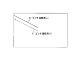
- FIG. 9 is a diagram for explaining a difference in transition direction of feature points depending on the presence or absence of pitch motion.
- FIG. 10 is a diagram for explaining the difference in the change direction of the feature point depending on the presence or absence of the yaw motion.
- FIG. 11 is a flowchart for explaining the calculation processing operation of the road environment recognition system according to the present invention.
- FIG. 12 is a diagram for explaining the transition direction of the feature points in the image processing area.
- FIG. 13 is a diagram for explaining another example of the image processing area narrowed as the host vehicle travels.
- FIG. 14 is a diagram illustrating an example of a rectangular image processing region that is set wider when a feature exists above a road.
- FIG. 15 is a diagram illustrating an example of a rectangular image processing region that is set wider when a feature object exists on the left side of the road.
- FIG. 16 is a diagram illustrating an example of a rectangular image processing region that is set wider when a feature object exists on the right side of the road.
- This road environment recognition system is provided in the own vehicle and recognizes features on the road based on the image information of the traveling direction of the imaged own vehicle. Therefore, this road environment recognition system is provided with an electronic control unit (ECU) 1 that performs such calculation processing.
- ECU electronice control unit
- the road environment recognition system includes a vehicle position detection device 11 and a map information database 12.
- the own vehicle position detection device 11 is a device that detects a position where the own vehicle exists. What is necessary is just to utilize what is called GPS (Global Positioning System) as this own vehicle position detection apparatus 11.
- GPS Global Positioning System
- the vehicle position information is transmitted to the electronic control device 1.
- the map information database 12 stores at least at least map information of roads on which vehicles can pass and feature information on features on the road (for example, traffic signs, road guide signs, etc.).
- the map information includes not only road shape information such as a straight road, a turning circuit, and a slope, but also information on the number of lanes (lane information).
- this map information includes information on the radius of curvature in the case of a turning circuit, and information on the gradient in the case of a slope.
- the feature object information at least feature type information and position information are stored.
- the position information of the feature is the position information of the feature with respect to the traveling direction of the road, the position information of the feature with respect to the width direction of the road, and the like.
- the position information with respect to the traveling direction is, for example, the position information of a feature corresponding to latitude and longitude, the position information of the feature corresponding to a distance marker (so-called kilopost), and the like.
- position information for the width direction at least information capable of identifying whether the position of the feature with respect to the road is the left side or the right side as viewed in the direction of travel of the road or the road is stored. .
- this road environment recognition system includes an imaging device 21 that captures the traveling direction of the vehicle.
- the imaging device 21 illustrated here captures the front of the vehicle.
- the imaging area of the imaging device 21 illustrated here is a rectangle. Information on the image captured by the imaging device 21 is transmitted to the electronic control device 1.
- this road environment recognition system for example, a feature point of a feature is searched from a captured image by template matching using local feature points such as SIFT and SURF, and the feature is recognized.
- this road environment recognition system includes a template database 13 in which various templates used for template matching are stored.
- the template is prepared, for example, as a vector representing a local feature of a feature (a so-called feature vector).
- a feature point for each type of feature object such as a feature point in the outer shape of the feature object, a feature point such as a character or a figure described in the feature object, and the like can be considered.
- the template database 13 stores various templates that may be used for template matching.
- the template may be stored for each of various feature objects in association with the feature type information. That is, a certain feature and a template for recognizing the feature are stored in the template database 13 in advance, and when the presence of the feature is recognized in step ST2 described later, A template corresponding to a feature may be read from the template database 13.
- the electronic control device 1 is provided with an image processing area calculation unit that obtains an image processing area to be implemented.
- the image processing area is a partial area of the image information captured by the imaging device 21 and includes at least a part of the feature.
- a feature point is included in a part of the feature.
- the central portion of the captured image is larger. Or it exists near the center. That is, the feature imaged at the farthest distance (hereinafter referred to as “the longest imageable distance”) at which the feature object can be imaged exists at or near the center of the captured image. Therefore, the image processing area calculation unit calculates a predetermined area including the central portion and at least a part of the feature among the images captured by the imaging device 21 as the image processing area.
- the longest distance that can be imaged is a distance on a flat road that is free of obstacles in the traveling direction and on a straight road.
- the feature on the captured image moves away from the center portion or near the center toward the outside of the image as the vehicle approaches the feature according to the position of the feature in the width direction of the road. For example, when the position of the feature with respect to the width direction of the road is above the road, the feature on the captured image moves from the central portion or near the center to the upper side of the captured image as the own vehicle approaches the feature. In addition, when the position of the feature with respect to the width direction of the road is on the left side of the road, the feature on the picked-up image moves on the picked-up image from the central portion or near the center to the upper left obliquely as the vehicle approaches the feature. Move.
- the image processing area calculation unit changes the image processing area in accordance with the movement of the feature (specifically, feature point) on the captured image. At that time, the image processing area after the change is made smaller than the image processing area when the feature is present in the central portion or near the center. That is, the image processing area calculation unit makes the image processing area smaller as the vehicle approaches the feature.
- the image processing area calculation unit determines the image processing area so that the feature object can be followed until the vehicle approaches and the image pickup device 21 cannot capture the feature object. Therefore, the image processing area calculation unit of this embodiment determines an image processing area from at least the following three patterns based on the position of the feature in the width direction of the road.
- the feature when the position of the feature with respect to the width direction of the road is above the road, the feature (feature point of the feature) shifts from the central portion or near the center of the captured image to the upper side as described above. For this reason, in this case, an area formed by a predetermined angle ⁇ of two vectors centered on the central portion of the captured image in which the transition direction of the feature point becomes a composite vector is set as an image processing area.
- the image processing area calculation unit estimates that the feature point 51 shifts above the captured image at the longest distance at which the feature object 50 can be imaged, and determines the image processing area 61 based on the estimation result of the shift direction of the feature point 51. Obtain ( Figure 2).
- the image processing region calculation unit narrows the image processing region 61 by gradually decreasing the predetermined angle ⁇ as the own vehicle approaches the feature object 50 (FIG. 3). At that time, the area of the image processing area 61 is reduced by at least one level.
- the upper central portion of the feature 50 is a feature point 51.
- the feature (feature point of the feature) is captured from the central portion or near the center of the captured image to the upper left obliquely as described above. Transform the top. For this reason, in this case, an area formed by a predetermined angle ⁇ of two vectors centered on the central portion of the captured image in which the transition direction of the feature point becomes a composite vector is set as an image processing area.
- the image processing area calculation unit estimates that the feature point 51 is shifted diagonally to the upper left of the captured image at the longest distance that the feature object 50 can be captured, and the image processing area is based on the estimation result of the shift direction of the feature point 51. 61 is obtained (FIG.
- the image processing area calculation unit narrows the image processing area 61 by gradually decreasing the predetermined angle ⁇ as the own vehicle approaches the feature object 50 (FIG. 5). At that time, the area of the image processing area 61 is reduced by at least one level.
- the upper left corner of the feature 50 is a feature point 51.
- the feature (feature point of the feature) is captured from the central portion or near the center of the captured image diagonally upward to the right as described above. Transform the top. For this reason, in this case, an area formed by a predetermined angle ⁇ of two vectors centered on the central portion of the captured image in which the transition direction of the feature point becomes a composite vector is set as an image processing area.
- the image processing area calculation unit estimates that the feature point 51 shifts obliquely upward to the right of the captured image at the longest distance at which the feature object 50 can be captured, and an image processing area based on the estimation result of the shift direction of the feature point 51. 61 is obtained (FIG. 6).
- the image processing region calculation unit narrows the image processing region 61 by gradually decreasing the predetermined angle ⁇ as the own vehicle approaches the feature object 50 (FIG. 7). At that time, the area of the image processing area 61 is reduced by at least one level.
- the upper right corner of the feature 50 is a feature point 51.
- the image processing region calculation unit makes the correct change direction (composite vector) of the feature point 51.
- the image processing area 61 may be corrected. That is, the image processing area calculation unit includes the current position of the feature 50 (feature point 51 of the feature 50) with respect to the current vehicle and the feature 50 with respect to the vehicle when the vehicle approaches the feature 50.
- the predetermined angle ⁇ of the image processing area 61 is gradually reduced as the vehicle approaches the characteristic object 50 so that the line connecting the position of (the characteristic point 51 of the characteristic object 50) is included in the image processing area 61. At that time, the area of the image processing area 61 is reduced by at least one level.
- the transition direction of the feature point 51 shown in the captured image (the above-mentioned line connecting the composite vector and the feature point 51) varies depending on where the vehicle is traveling in the width direction of the road. For example, when the road has a plurality of lanes, the position of the feature point 51 reflected in the captured image is different for each lane, and thus the direction of change of the feature point 51 is different for each lane. For this reason, the image processing region calculation unit may change the transition direction of the feature point 51 in accordance with the lane in which the host vehicle is traveling. However, the case where the change is possible is a case where the horizontal position and the height position of the feature object 50 (feature point 51) are stored in the map information database 12 as feature object information.
- the lateral position is a position in the width direction of the road, for example, a position calculated from the central portion of the traveling lane of the own vehicle in the width direction of the road.
- the position in the height direction is a position in the vertical direction calculated from the road surface of the road or a place having the same height as the road surface.
- FIG. 8 shows the transition direction of the feature point 51 for each lane when traveling on a three-lane road of lanes A, B, and C.
- the solid line in the figure below is the direction of transition of the feature point 51 when traveling on the lane A.
- the alternate long and short dash line is the direction of transition of the feature point 51 when traveling in the lane B.
- An alternate long and two short dashes line is a transition direction of the feature point 51 when the vehicle travels on the lane C.
- the change direction of the feature point 51 is smaller in the height direction as the vehicle travels in a lane away from the feature object 50.
- the travel lane of the host vehicle may be grasped from a plurality of lanes on the road.
- the traveling lane of the own vehicle may be grasped based on, for example, a captured image of the imaging device 21, and if the own vehicle position detection device 11 is highly accurate so that the difference in the lane can be grasped, You may grasp
- the direction of change of the feature point 51 according to the traveling position of the vehicle in the width direction of the road can be known by continuously monitoring the feature point 51 as the vehicle travels. For this reason, it is not always necessary to grasp the traveling lane of the own vehicle when calculating the direction of transition.
- the description so far is for a state where the vehicle is running on a flat road and a straight road at a constant speed.
- the own vehicle performs a yaw motion, a roll motion, and a pitch motion, and the transition direction of the feature point 51 shown in the captured image (the above-described line connecting the feature vector 51) is flat. Different from roads and straight roads. Therefore, before the transition direction of the feature point 51 is grasped from the captured image, if the own vehicle is performing a yaw motion, a roll motion, or a pitch motion, a deviation occurs in the estimation result of the transition direction and is calculated.
- the image processing area calculation unit calibrates the optical axis direction of the imaging device 21 according to the traveling posture of the host vehicle, and the image including the transition direction of the feature point 51 even if the host vehicle performs a yaw motion or the like.
- the processing area 61 is configured to be calculated.
- the image processing area calculation unit estimates the running posture of the vehicle during yaw movement based on the detection result of the yaw rate sensor 31, and the running posture of the vehicle during roll motion based on the detection result of the lateral acceleration sensor 32.
- the traveling posture of the host vehicle during the roll motion is estimated based on the detection result of the longitudinal acceleration sensor 33.
- the image processing area calculation unit may estimate the traveling posture of the host vehicle based on a change in the load of each wheel.
- FIG. 9 is an example showing a difference in transition direction of the feature point 51 depending on the presence or absence of the pitch motion.
- the solid line in this figure indicates the transition direction of the feature point 51 tracked with the pitch angle set to 0 degrees (that is, with the optical axis of the imaging device 21 being straight).
- the broken line indicates the transition direction of the feature point 51 tracked with the pitch angle (that is, the optical axis of the imaging device 21) tilted upward by 5 degrees.
- FIG. 10 is an example showing a difference in the transition direction of the feature point 51 depending on the presence or absence of the yaw motion.
- the solid line in this figure indicates the transition direction of the feature point 51 tracked in a state where there is no yaw movement (that is, a state where the optical axis of the imaging device 21 is straight).
- a broken line indicates the transition direction of the feature point 51 tracked in a state where the optical axis of the imaging device 21 is inclined 5 degrees in the rightward yaw direction.
- this image processing area calculation unit changes the transition direction of the feature point 51 in accordance with the traveling posture of the host vehicle.
- the image processing area calculation unit may use the change in the change direction of the feature point 51 according to the lane in which the host vehicle is traveling. That is, the image processing area calculation unit changes the transition direction of the feature point 51 in accordance with the traveling lane of the own vehicle and / or the traveling posture of the own vehicle.
- the traveling posture of the own vehicle and the optical axis direction of the imaging device 21 also change depending on the number of passengers, the boarding position, the load amount of the luggage, and the loading position. For example, when the load amount of the luggage at the rear of the vehicle is large, the traveling posture of the own vehicle (the optical axis direction of the imaging device 21) changes in the pitch direction as compared with the case where the load amount is small. Further, when the occupant gets on either the left or right side of the vehicle, the traveling posture of the vehicle (the optical axis direction of the imaging device 21) changes in the roll direction as compared to the case where the occupant gets on the left and right evenly. . Such changes are already known when you start running.
- the optical axis direction of the imaging device 21 is calibrated during traveling (particularly during calculation of the image processing area 61), thereby causing the feature 50 to be unrecognizable or causing a recognition delay.
- the image processing area calculation unit is configured to calibrate the deviation in the optical axis direction of the imaging device 21 due to the change of the occupant or the luggage when the opening / closing of the door or the opening / closing of the trunk is detected.
- the vehicle position detection unit of the electronic control device 1 detects the current vehicle position on the road based on the vehicle position information received from the vehicle position detection device 11 and the map information in the map information database 12 ( Step ST1).
- the feature detection unit of the electronic control device 1 determines whether or not the feature 50 to be recognized exists in the traveling direction of the host vehicle (step ST2). This determination is performed using, for example, own vehicle position information, map information, feature information (position information of the feature 50 with respect to the road traveling direction), and imaging area information of the imaging device 21. In this case, it is determined whether or not the feature 50 exists within a predetermined distance in the traveling direction of the host vehicle. If the feature 50 does not exist within the predetermined distance, the traveling direction of the host vehicle is determined. If it is determined that there is no feature object 50 to be recognized and the feature object 50 exists within a predetermined distance, the feature object 50 to be recognized exists in the traveling direction of the vehicle. judge.
- the term “within the predetermined distance” refers to a distance within which the imaging device 21 can image the feature object, and includes the longest distance that the above-described feature object 50 can be imaged.
- the imaging device 21 may not always be able to capture an image of the feature 50 existing within a predetermined distance when the currently running road or the road ahead is a turning circuit or a slope. However, the imaging device 21 continues to travel as it is, for example, when moving from an uphill road to a downhill road where the feature 50 exists, or from a turning circuit to a straight road where the feature 50 exists.
- the feature 50 can be imaged.
- the imaging device 21 can actually image the feature object 50 at this time, if the feature object 50 exists within a predetermined distance, the object to be recognized is recognized in the traveling direction of the host vehicle. It is determined that the characteristic object 50 is present.
- step ST1 If it is determined that the feature 50 does not exist, the process returns to step ST1 and the same calculation process is repeated.
- the image processing area calculation unit of the electronic control device 1 performs feature object information (type information of the feature object 50, position information of the feature object 50 with respect to the width direction of the road). ) Is read from the map information database 12 and a template suitable for recognition of the feature 50 is read from the template database 13 (step ST3). That is, in this step ST3, the approximate position of the feature 50 with respect to the road from the position information of the feature 50 with respect to the width direction of the road (that is, the left or right of the feature 50 as viewed in the traveling direction of the road) Whether the object 50 exists) and a template is determined based on the type information of the feature object 50.
- the image processing area calculation unit determines the image processing area 61 on the captured image of the imaging device 21 based on the position information of the feature 50 with respect to the width direction of the road in step ST3 (step ST4).
- the image processing area 61 is determined by calculation as described above.
- the feature object detection unit of the electronic control device 1 After the image processing area 61 is determined, the feature object detection unit of the electronic control device 1 performs template matching on the image information in the image processing area 61 using the template determined in step ST3, and the image processing area 61 The feature point 51 of the feature object 50 is detected from the inside (step ST5).
- the feature detection unit determines, for example, whether or not the vehicle has traveled a predetermined distance from the first feature point detection (step ST6). This determination is a previous determination for calculating the relative distances X and Y in the lateral direction and the height direction of the feature object 50 (feature point 51) with respect to the own vehicle, and is a feature that can perform the calculation. This is to know whether or not the point 51 has moved. Accordingly, as the predetermined distance, the moving distance of the own vehicle until the transition of the feature point 51 at which the relative distances X and Y can be calculated may be set.
- the feature object detection unit determines that information sufficient to calculate the relative distances X and Y has not been obtained yet, and returns to step ST5 to detect the feature point 51. repeat.
- the feature detection unit determines that there is a movement of the feature point 51 suitable for calculating the relative distances X and Y, and the feature 50 for the vehicle (feature)
- the relative distances X and Y of the horizontal direction and the height direction of the point 51) are calculated (step ST7).
- the image processing area calculation unit measures the running posture of the host vehicle using the detection result of the yaw rate sensor 31 and the like (step ST8).
- the image processing area calculation unit obtains the transition direction of the feature point 51 based on the relative distances X and Y obtained at step ST7 and the traveling posture of the host vehicle measured at step ST8, and the image processing area 61 based on the transition direction. Is changed (step ST9).
- an image processing area 61 that includes the transition direction and is smaller than step ST4 is determined.
- the feature object detection unit After the image processing area 61 is narrowed, the feature object detection unit performs template matching on the image information in the new image processing area 61 using the template determined in step ST3. A feature point 51 of the feature 50 is detected (step ST10).
- the feature object detection unit calculates the relative distances X and Y of the feature object 50 (feature point 51) with respect to the host vehicle in the horizontal direction and the height direction, and the progression of the feature object 50 (feature point 51) with respect to the host vehicle.
- a relative distance Z in the direction is calculated (step ST11).
- the relative distance Z in the traveling direction is calculated based on the image processing result of the image information in the image processing area 61 in the same manner as the relative distances X and Y.
- the image processing area calculation unit determines whether or not the recognition end condition for the feature 50 is satisfied (step ST12). This determination is to see whether or not the vehicle has sufficiently approached the feature object 50 and has recognized the feature object 50. If the feature 50 is recognized sufficiently close, it is determined that the recognition end condition is satisfied. On the other hand, when the feature object 50 can be further recognized by approaching the feature object 50, it is determined that the recognition end condition is not satisfied. For this reason, here, for example, if the feature point 51 no longer exists on the captured image, it is determined that the recognition end condition is satisfied, and if the feature point 51 exists on the captured image, the recognition end condition Is determined not to hold.
- the image processing area calculation unit returns to step ST8 to measure the traveling posture of the host vehicle, and the image processing area calculation unit proceeds to step ST9. Based on the travel posture and the relative distances X and Y obtained in step ST11, the transition direction of the feature point 51 is obtained, and a smaller image processing area 61 is determined. In this case, if the image processing area 61 is too small to be further narrowed, the process proceeds to step ST10 with the current image processing area 61 being kept.
- step ST11 when the vehicle is sufficiently close to the feature 50 and recognizes the feature 50, the accurate relative distances X, Y, and Z can be obtained in step ST11. In this case, since it is determined in step ST12 that the condition for ending the recognition of the feature object 50 is satisfied, this calculation process is terminated.
- the image processing area calculation unit determines the image processing area 61 of FIG. 4 in step ST4, performs template matching on the image information of the image processing area 61 in step ST5, and performs a feature from the image processing area 61. A feature point 51 of the object 50 is detected.
- the feature detection unit observes the movement of the feature point 51 that changes with the progress of the host vehicle, and thereby, in step ST7, the relative distance X, the horizontal direction and the height direction of the feature 50 (feature point 51) with respect to the host vehicle. Y is calculated. Note that X and Y in FIG. 4 are conceptual for explaining the relative distance, and are different from the relative distance calculated here.
- the image processing area calculation unit proceeds to step ST9, obtains the transition direction of the feature point 51 based on the relative distances X and Y and the traveling posture of the own vehicle (FIG. 12), and based on the transition direction, the transition.
- An image processing area 61 that includes a direction and is smaller than step ST4 is determined (FIG. 5).
- the image processing area calculation unit performs template matching on the image information of the new image processing area 61, and detects the feature point 51 of the feature 50 from the image processing area 61.
- the feature detection unit calculates relative distances X, Y, and Z with respect to the feature 50 (feature point 51) with respect to the own vehicle in step ST11 by observing the movement of the feature point 51 that changes with the progress of the own vehicle.
- the electronic control unit 1 repeats the arithmetic processing after step ST8 until the recognition end condition for the feature 50 is satisfied.
- this road environment recognition system reduces the amount of image information necessary for image processing by reducing the image processing area 61 as the host vehicle approaches the feature 50, so that the recognition accuracy is not lowered.
- the feature 50 can be recognized while reducing the processing load.
- the road environment recognition system sets the image processing area 61 to be wider once and then reduces the image processing area 61 by at least one step, the detected vehicle position is in the traveling direction with respect to the feature 50. Even if there is a large deviation, it is possible to recognize the feature 50 with such high accuracy.
- the road environment recognition system uses the wide image processing area 61 and the relative distances X and Y in the horizontal direction and the height direction therebetween.
- the image processing area 61 is narrowed to obtain the relative distances X and Y in the lateral direction and the height direction. Even if the position in the horizontal direction and the position in the height direction are not stored, the feature object 50 can be recognized while reducing the processing load without reducing the recognition accuracy.
- the recognition of the feature 50 starts even if the detected vehicle position deviates greatly in the traveling direction with respect to the feature 50.
- the feature point 51 of the feature 50 can continue to be included in the image processing area 61 from the distant point of time to the vicinity when the recognition end condition of the feature 50 is satisfied. 50 recognition accuracy can be improved.
- This road environment recognition system uses a fan-shaped image processing area 61 in which the feature point 51 is continuously included. Since it is used, such an abnormal value can be omitted.
- the feature detection unit outputs the relative distances X, Y, and Z obtained in the step immediately before the recognition end condition for the feature 50 is satisfied as the recognition result of the feature 50. Further, as the relative distances X, Y, and Z are smaller, the feature 50 is recognized near the own vehicle, and the accuracy of the relative distances X, Y, and Z is increased.
- the recognition result of the feature 50 may be output together with a parameter (such as confidence level) indicating the high accuracy. For example, when the output destination of the recognition result is the own vehicle position detection unit of the electronic control device 1, the own vehicle position detection unit can improve the detection accuracy of the own vehicle position based on the recognition result.
- the own vehicle position detection unit obtains the relative distance Z in the traveling direction between the own vehicle and the feature 50 based on the own vehicle position information and the position information of the feature 50 in the map information database 12.
- the relative distance Z based on the vehicle position information is compared with the relative distance Z in the recognition result of the feature 50, and when there is a deviation between these relative distances Z, the vehicle position is corrected based on the difference. .
- the detection accuracy of the vehicle position by the vehicle position detection unit is improved.
- the image processing area 61 obtained in step ST4 of the embodiment has a larger area than the image processing area 61 calculated in step ST9. Therefore, when these are compared, the image processing area 61 in step ST4 has a higher processing load in template matching than the image processing area 61 in step ST9.
- the image processing area 61 in step ST4 has a higher processing load in template matching than the image processing area 61 in step ST9.
- the own vehicle and the feature object 50 are far away from each other, and the movement of the feature point 51 on the captured image is small when the own vehicle advances slightly. . Therefore, since it is difficult to confirm the movement of the feature point 51 at this time, even if there is a change of the feature point 51 that allows the relative distances X and Y to be calculated, this may not be grasped.
- the frame rate of the image processing area 61 when performing template matching in the image processing area 61 in step ST4 is lowered to make it easier to confirm the movement of the feature point 51 on the captured image. This also contributes to a reduction in the processing load during the template matching.
- step ST ⁇ b> 9 the predetermined angle (center angle) of the fan-shaped image processing region 61 is reduced as the vehicle approaches the feature 50.
- the processing area 61 is reduced.
- the feature point 51 of the feature 50 moves away from the central portion of the captured image as the own vehicle approaches the feature 50.
- the image processing area calculation unit of the present modification reduces the image processing area 61 by excluding from the image processing area 61 at least the area closer to the center than the feature 50 as shown in FIG. Let Thereby, the road environment recognition system of this modification can further reduce the processing load.
- Modification 3 This modification is obtained by replacing the image processing area 61 in step ST4 with the following image processing area 62 in the road environment recognition system of the above-described embodiment and modifications 1 and 2.
- the feature object 50 exists at or near the center of the captured image as described above. Performing template matching at a location away from the central portion or near the center can be said to be a wasteful calculation process. For this reason, it is desirable to exclude the center part or a place away from the vicinity of the center from the image processing area determined in step ST4.
- step ST4 of the present modification the rectangular image processing area 62 is calculated so that the central portion or the vicinity of the center is wide and the place away from the central portion or the vicinity of the center is excluded.
- the road environment recognition system of this modification can reduce the load of the arithmetic processing while improving the recognition accuracy of the feature object 50.
- the rectangular image processing area 62 has sides parallel to the four sides of the captured image.
- the rectangular shape of FIG. 14 includes the transition direction of the feature point 51 from the central portion or the vicinity of the center to the upper side, and the central portion or the vicinity of the center is widened with the transition direction as the center.
- the image processing area 62 is assumed. In this case, when the own vehicle approaches the feature 50, for example, the fan-shaped image processing area 61 of FIG. 3 is obtained in step ST9.
- the center portion in the captured image or the corner portion diagonally to the upper left of the center becomes a useless area that does not require template matching.
- the transition direction of the feature point 51 from the central portion or the vicinity of the center to the diagonally upper left is included, and the central portion or the vicinity of the center is widened with the transition direction as the center in FIG.
- a rectangular image processing area 62 is assumed.
- the fan-shaped image processing area 61 of FIG. 5 is obtained in step ST9.
- the central portion in the captured image or the corner portion on the upper right side of the vicinity of the center is a useless area that does not require template matching.
- the transition direction of the feature point 51 from the central portion or the vicinity of the center to the diagonally right and left upper direction is included, and the central portion or the vicinity of the center is widened with the transition direction as the center.
- a rectangular image processing area 62 is assumed. In this case, when the vehicle approaches the feature 50, for example, the fan-shaped image processing area 61 of FIG. 7 is obtained in step ST9.
Abstract
Description
本発明に係る道路環境認識システムの実施例を図1から図12に基づいて説明する。 [Example]
An embodiment of a road environment recognition system according to the present invention will be described with reference to FIGS.
実施例のステップST4で求めた画像処理領域61は、その後ステップST9で演算される画像処理領域61よりも広い面積を持っている。これが為、これらを比較すると、ステップST4の画像処理領域61は、テンプレートマッチングの際の演算処理の負荷がステップST9の画像処理領域61よりも高くなる。しかしながら、ステップST4の画像処理領域61を用いるときは、自車と特徴物50との間が大きく離れており、僅かに自車が進んだだけでは撮像画像上での特徴点51の動きが小さい。故に、このときには、特徴点51の動きを確認しにくいので、相対距離X,Yの演算が可能になる特徴点51の変移があったとしても、これを把握できない可能性がある。 [Modification 1]
The
前述した実施例及び変形例1の道路環境認識システムにおいては、ステップST9で、自車が特徴物50に近づくほど扇型の画像処理領域61の所定角度(中心角)を小さくすることによって、画像処理領域61を小さくする。しかしながら、その特徴物50の特徴点51は、自車が特徴物50に近づくほど、撮像画像の中央部分から離れていく。これが為、少なくともその特徴物50よりも中央部分側の領域を画像処理領域61から除外したとしても、その特徴物50の特徴点51の検出に悪影響を与えることはない。従って、本変形例の画像処理領域演算部には、図13に示す様に、少なくともその特徴物50よりも中央部分側の領域を画像処理領域61から除外させることで、画像処理領域61を減少させる。これにより、本変形例の道路環境認識システムは、演算処理の負荷を更に軽減させることができる。 [Modification 2]
In the road environment recognition system according to the above-described embodiment and the first modification, in step ST <b> 9, the predetermined angle (center angle) of the fan-shaped
本変形例は、前述した実施例及び変形例1,2の道路環境認識システムにおいて、ステップST4の画像処理領域61を下記の画像処理領域62に置き換えたものである。自車と特徴物50との間が大きく離れているときは、前述した様に特徴物50が撮像画像の中央部分又は中央付近に存在しているので、ステップST4の画像処理領域61において、その中央部分又は中央付近から離れている場所でテンプレートマッチングを行うことは無駄な演算処理と云える。この為、その中央部分又は中央付近から離れている場所は、ステップST4で決められる画像処理領域から除外することが望ましい。また、自車と特徴物50との間が大きく離れているときには、自車に対する特徴物50の横方向と高さ方向の相対距離X,Yが特徴物情報等から明らかにできなければ、その中央部分又は中央付近でのテンプレートマッチングを広範囲で行うことが、その特徴物50の認識精度を上げる上で望ましい。 [Modification 3]
This modification is obtained by replacing the
11 自車位置検出装置
12 地図情報データベース
13 テンプレートデータベース
21 撮像装置
50 特徴物
51 特徴点
61,62 画像処理領域 DESCRIPTION OF
Claims (9)
- 自車の進行方向を撮像する撮像装置と、
自車の進行方向に道路上の特徴物が存在している場合、前記撮像装置で撮像された画像の内、中央部分と前記特徴物の少なくとも一部分とを含む所定領域を画像処理領域とし、該画像処理領域を自車が前記特徴物に近づくほど小さくする画像処理領域演算部と、
前記画像処理領域の画像情報に基づいて前記特徴物を検出する特徴物検出部と、
を備えることを特徴とした道路環境認識システム。 An imaging device for imaging the traveling direction of the vehicle;
When there is a feature on the road in the traveling direction of the host vehicle, a predetermined area including a central part and at least a part of the feature is included in the image captured by the imaging device, and the image processing area An image processing area calculation unit that makes the image processing area smaller as the vehicle approaches the feature;
A feature detection unit that detects the feature based on image information of the image processing region;
A road environment recognition system characterized by comprising: - 前記画像処理領域演算部は、前記中央部分を中心とした所定角度からなる領域を前記画像処理領域とすることを特徴とした請求項1記載の道路環境認識システム。 The road environment recognition system according to claim 1, wherein the image processing area calculation unit uses an area having a predetermined angle centered on the central portion as the image processing area.
- 前記画像処理領域演算部は、自車が前記特徴物に近づくにつれて、少なくとも矩形領域から前記中央部分を中心とした所定角度からなる領域に前記画像処理領域を変更することを特徴とした請求項1記載の道路環境認識システム。 The image processing area calculation unit changes the image processing area from a rectangular area to an area having a predetermined angle centered on the central portion as the host vehicle approaches the feature. The road environment recognition system described.
- 前記画像処理領域演算部は、自車が前記特徴物に近づくにつれて、前記画像処理領域における前記特徴物よりも前記中央部分側の領域を少なくとも当該画像処理領域から除外することを特徴とした請求項2記載の道路環境認識システム。 The image processing area calculation unit, as the own vehicle approaches the feature, excludes at least the area on the central portion side of the feature in the image processing area from the image processing area. 2. The road environment recognition system according to 2.
- 前記画像処理領域演算部は、自車が前記特徴物に近づくほど前記画像処理領域の前記所定角度を小さくすることを特徴とした請求項2,3又は4に記載の道路環境認識システム。 The road environment recognition system according to claim 2, 3 or 4, wherein the image processing area calculation unit reduces the predetermined angle of the image processing area as the own vehicle approaches the feature.
- 前記画像処理領域演算部は、現在の自車に対する前記特徴物の位置と自車が当該特徴物に近づいたときの自車に対する当該特徴物の位置とを結ぶ線が前記画像処理領域に含まれるよう当該画像処理領域の前記所定角度を小さくすることを特徴とした請求項2,3又は4に記載の道路環境認識システム。 The image processing area calculation unit includes a line connecting the current position of the feature with respect to the own vehicle and the position of the feature with respect to the own vehicle when the own vehicle approaches the feature. 5. The road environment recognition system according to claim 2, wherein the predetermined angle of the image processing area is reduced.
- 前記画像処理領域演算部は、自車の走行車線又は/及び自車の走行姿勢に応じて前記特徴物を結ぶ線の変更を行うことを特徴とした請求項6記載の道路環境認識システム。 The road environment recognition system according to claim 6, wherein the image processing area calculation unit changes a travel lane of the own vehicle or / and a line connecting the features according to a travel posture of the own vehicle.
- 前記画像処理領域演算部は、前記所定角度を成す前記中心を始点にした2つのベクトルの合成ベクトル上に前記特徴物の特徴点が来るよう前記画像処理領域の演算を行うことを特徴とした請求項2から6の内の何れか1つに記載の道路環境認識システム。 The image processing area calculation unit calculates the image processing area so that a feature point of the feature comes on a combined vector of two vectors starting from the center forming the predetermined angle. Item 7. The road environment recognition system according to any one of Items 2 to 6.
- 前記画像処理領域演算部は、自車の走行車線又は/及び自車の走行姿勢に応じて前記合成ベクトルの変更を行うことを特徴とした請求項8記載の道路環境認識システム。 The road environment recognition system according to claim 8, wherein the image processing area calculation unit changes the composite vector in accordance with a traveling lane of the own vehicle or / and a traveling posture of the own vehicle.
Priority Applications (5)
| Application Number | Priority Date | Filing Date | Title |
|---|---|---|---|
| US14/763,338 US20150363653A1 (en) | 2013-01-25 | 2013-01-25 | Road environment recognition system |
| PCT/JP2013/051663 WO2014115319A1 (en) | 2013-01-25 | 2013-01-25 | Road environment recognition system |
| EP13873098.1A EP2950291A4 (en) | 2013-01-25 | 2013-01-25 | Road environment recognition system |
| JP2014558398A JP5949955B2 (en) | 2013-01-25 | 2013-01-25 | Road environment recognition system |
| CN201380071342.6A CN104937648A (en) | 2013-01-25 | 2013-01-25 | Road environment recognition system |
Applications Claiming Priority (1)
| Application Number | Priority Date | Filing Date | Title |
|---|---|---|---|
| PCT/JP2013/051663 WO2014115319A1 (en) | 2013-01-25 | 2013-01-25 | Road environment recognition system |
Publications (1)
| Publication Number | Publication Date |
|---|---|
| WO2014115319A1 true WO2014115319A1 (en) | 2014-07-31 |
Family
ID=51227133
Family Applications (1)
| Application Number | Title | Priority Date | Filing Date |
|---|---|---|---|
| PCT/JP2013/051663 WO2014115319A1 (en) | 2013-01-25 | 2013-01-25 | Road environment recognition system |
Country Status (5)
| Country | Link |
|---|---|
| US (1) | US20150363653A1 (en) |
| EP (1) | EP2950291A4 (en) |
| JP (1) | JP5949955B2 (en) |
| CN (1) | CN104937648A (en) |
| WO (1) | WO2014115319A1 (en) |
Cited By (3)
| Publication number | Priority date | Publication date | Assignee | Title |
|---|---|---|---|---|
| CN105571606A (en) * | 2014-11-04 | 2016-05-11 | 沃尔沃汽车公司 | Methods and systems for enabling improved positioning of a vehicle |
| JP2017102928A (en) * | 2015-12-03 | 2017-06-08 | ローベルト ボツシユ ゲゼルシヤフト ミツト ベシユレンクテル ハフツングRobert Bosch Gmbh | Detection of inclination of two wheeler |
| JP2018017652A (en) * | 2016-07-29 | 2018-02-01 | エヌ・ティ・ティ・インフラネット株式会社 | Survey information management device and survey information management method |
Families Citing this family (9)
| Publication number | Priority date | Publication date | Assignee | Title |
|---|---|---|---|---|
| JP2016176769A (en) * | 2015-03-19 | 2016-10-06 | クラリオン株式会社 | Information processing device and vehicle position detection method |
| DE102016213493A1 (en) * | 2016-07-22 | 2018-01-25 | Conti Temic Microelectronic Gmbh | Camera device for recording a surrounding area of an own vehicle and method for providing a driver assistance function |
| KR20190028528A (en) * | 2016-07-26 | 2019-03-18 | 닛산 지도우샤 가부시키가이샤 | Magnetic position estimation method and magnetic position estimation apparatus |
| JP6656129B2 (en) * | 2016-09-28 | 2020-03-04 | 日立オートモティブシステムズ株式会社 | Image processing device, imaging device |
| JP7120835B2 (en) * | 2018-07-18 | 2022-08-17 | トヨタ自動車株式会社 | Image processing device |
| US11293762B2 (en) * | 2019-06-18 | 2022-04-05 | Here Global B.V. | System and methods for generating updated map data |
| JP2021092967A (en) * | 2019-12-10 | 2021-06-17 | トヨタ自動車株式会社 | Image processing system, image processor, and program |
| US11893698B2 (en) * | 2020-11-04 | 2024-02-06 | Samsung Electronics Co., Ltd. | Electronic device, AR device and method for controlling data transfer interval thereof |
| CN116704224B (en) * | 2023-08-08 | 2023-11-17 | 深圳卡尔文科技有限公司 | Marker identification method and identification device based on deep learning |
Citations (5)
| Publication number | Priority date | Publication date | Assignee | Title |
|---|---|---|---|---|
| JP2000293670A (en) * | 1999-04-08 | 2000-10-20 | Asia Air Survey Co Ltd | Method and device for automatically recognizing road sign of video picture and storage medium storing program for automatically recognizing road sign |
| JP2006003994A (en) | 2004-06-15 | 2006-01-05 | Calsonic Kansei Corp | Road sign recognition device |
| JP2007200005A (en) | 2006-01-26 | 2007-08-09 | Honda Motor Co Ltd | Operation support device |
| JP2007241469A (en) | 2006-03-06 | 2007-09-20 | Toyota Motor Corp | Image processing system |
| WO2011048718A1 (en) * | 2009-10-20 | 2011-04-28 | パナソニック株式会社 | Sign recognition device and sign recognition method |
Family Cites Families (8)
| Publication number | Priority date | Publication date | Assignee | Title |
|---|---|---|---|---|
| US6978037B1 (en) * | 2000-11-01 | 2005-12-20 | Daimlerchrysler Ag | Process for recognition of lane markers using image data |
| JP4321821B2 (en) * | 2005-01-28 | 2009-08-26 | アイシン・エィ・ダブリュ株式会社 | Image recognition apparatus and image recognition method |
| EP2023265A1 (en) * | 2007-07-30 | 2009-02-11 | Delphi Technologies, Inc. | Method for recognising an object |
| JP2011511281A (en) * | 2008-02-04 | 2011-04-07 | テレ アトラス ノース アメリカ インコーポレイテッド | Map matching method with objects detected by sensors |
| JP4937199B2 (en) * | 2008-06-25 | 2012-05-23 | 日立オートモティブシステムズ株式会社 | Auto light device |
| JP5074365B2 (en) * | 2008-11-28 | 2012-11-14 | 日立オートモティブシステムズ株式会社 | Camera device |
| JP2010146478A (en) * | 2008-12-22 | 2010-07-01 | Toyota Motor Corp | Object detection device |
| JP5375752B2 (en) * | 2009-07-15 | 2013-12-25 | 日産自動車株式会社 | Vehicle driving support device |
-
2013
- 2013-01-25 EP EP13873098.1A patent/EP2950291A4/en not_active Withdrawn
- 2013-01-25 JP JP2014558398A patent/JP5949955B2/en not_active Expired - Fee Related
- 2013-01-25 US US14/763,338 patent/US20150363653A1/en not_active Abandoned
- 2013-01-25 CN CN201380071342.6A patent/CN104937648A/en active Pending
- 2013-01-25 WO PCT/JP2013/051663 patent/WO2014115319A1/en active Application Filing
Patent Citations (5)
| Publication number | Priority date | Publication date | Assignee | Title |
|---|---|---|---|---|
| JP2000293670A (en) * | 1999-04-08 | 2000-10-20 | Asia Air Survey Co Ltd | Method and device for automatically recognizing road sign of video picture and storage medium storing program for automatically recognizing road sign |
| JP2006003994A (en) | 2004-06-15 | 2006-01-05 | Calsonic Kansei Corp | Road sign recognition device |
| JP2007200005A (en) | 2006-01-26 | 2007-08-09 | Honda Motor Co Ltd | Operation support device |
| JP2007241469A (en) | 2006-03-06 | 2007-09-20 | Toyota Motor Corp | Image processing system |
| WO2011048718A1 (en) * | 2009-10-20 | 2011-04-28 | パナソニック株式会社 | Sign recognition device and sign recognition method |
Non-Patent Citations (1)
| Title |
|---|
| See also references of EP2950291A4 |
Cited By (4)
| Publication number | Priority date | Publication date | Assignee | Title |
|---|---|---|---|---|
| CN105571606A (en) * | 2014-11-04 | 2016-05-11 | 沃尔沃汽车公司 | Methods and systems for enabling improved positioning of a vehicle |
| JP2017102928A (en) * | 2015-12-03 | 2017-06-08 | ローベルト ボツシユ ゲゼルシヤフト ミツト ベシユレンクテル ハフツングRobert Bosch Gmbh | Detection of inclination of two wheeler |
| JP7179440B2 (en) | 2015-12-03 | 2022-11-29 | ローベルト ボツシユ ゲゼルシヤフト ミツト ベシユレンクテル ハフツング | Tilt detection in motorcycles |
| JP2018017652A (en) * | 2016-07-29 | 2018-02-01 | エヌ・ティ・ティ・インフラネット株式会社 | Survey information management device and survey information management method |
Also Published As
| Publication number | Publication date |
|---|---|
| JP5949955B2 (en) | 2016-07-13 |
| JPWO2014115319A1 (en) | 2017-01-26 |
| CN104937648A (en) | 2015-09-23 |
| EP2950291A1 (en) | 2015-12-02 |
| US20150363653A1 (en) | 2015-12-17 |
| EP2950291A4 (en) | 2016-10-12 |
Similar Documents
| Publication | Publication Date | Title |
|---|---|---|
| JP5949955B2 (en) | Road environment recognition system | |
| EP3306429B1 (en) | Position estimation device and position estimation method | |
| US9740942B2 (en) | Moving object location/attitude angle estimation device and moving object location/attitude angle estimation method | |
| JP4343536B2 (en) | Car sensing device | |
| JP5966747B2 (en) | Vehicle travel control apparatus and method | |
| US20090118994A1 (en) | Vehicle and lane recognizing device | |
| US10493987B2 (en) | Target-lane relationship recognition apparatus | |
| US11092442B2 (en) | Host vehicle position estimation device | |
| JP7143722B2 (en) | Vehicle position estimation device | |
| JP6911312B2 (en) | Object identification device | |
| WO2016117507A1 (en) | Section-line recognition device | |
| JP4702149B2 (en) | Vehicle positioning device | |
| JP2017138660A (en) | Object detection method, object detection device and program | |
| JP2013036856A (en) | Driving support apparatus | |
| WO2019065970A1 (en) | Vehicle exterior recognition device | |
| US10916034B2 (en) | Host vehicle position estimation device | |
| CN113795726B (en) | Self-position correction method and self-position correction device | |
| CN111959482A (en) | Autonomous driving device and method | |
| JP2006321421A (en) | Travel controller for vehicle | |
| US11156466B2 (en) | Lane determination device | |
| TWI726810B (en) | Obstacle tracking system and method combined with image data | |
| WO2021145032A1 (en) | Nearby vehicle position estimation system, and nearby vehicle position estimation program | |
| JP2021114059A (en) | Risk determination system and risk determination program | |
| JP2023077891A (en) | Travel path estimation device, and travel path estimation program | |
| CN117434552A (en) | Vehicle detection device |
Legal Events
| Date | Code | Title | Description |
|---|---|---|---|
| 121 | Ep: the epo has been informed by wipo that ep was designated in this application |
Ref document number: 13873098 Country of ref document: EP Kind code of ref document: A1 |
|
| ENP | Entry into the national phase |
Ref document number: 2014558398 Country of ref document: JP Kind code of ref document: A |
|
| REEP | Request for entry into the european phase |
Ref document number: 2013873098 Country of ref document: EP |
|
| WWE | Wipo information: entry into national phase |
Ref document number: 14763338 Country of ref document: US Ref document number: 2013873098 Country of ref document: EP |
|
| NENP | Non-entry into the national phase |
Ref country code: DE |