WO2019065970A1 - Vehicle exterior recognition device - Google Patents
Vehicle exterior recognition device Download PDFInfo
- Publication number
- WO2019065970A1 WO2019065970A1 PCT/JP2018/036265 JP2018036265W WO2019065970A1 WO 2019065970 A1 WO2019065970 A1 WO 2019065970A1 JP 2018036265 W JP2018036265 W JP 2018036265W WO 2019065970 A1 WO2019065970 A1 WO 2019065970A1
- Authority
- WO
- WIPO (PCT)
- Prior art keywords
- feature point
- vehicle
- obstacle
- road surface
- image
- Prior art date
Links
Images


Classifications
-
- G—PHYSICS
- G06—COMPUTING; CALCULATING OR COUNTING
- G06V—IMAGE OR VIDEO RECOGNITION OR UNDERSTANDING
- G06V20/00—Scenes; Scene-specific elements
- G06V20/50—Context or environment of the image
- G06V20/56—Context or environment of the image exterior to a vehicle by using sensors mounted on the vehicle
- G06V20/58—Recognition of moving objects or obstacles, e.g. vehicles or pedestrians; Recognition of traffic objects, e.g. traffic signs, traffic lights or roads
-
- B—PERFORMING OPERATIONS; TRANSPORTING
- B60—VEHICLES IN GENERAL
- B60R—VEHICLES, VEHICLE FITTINGS, OR VEHICLE PARTS, NOT OTHERWISE PROVIDED FOR
- B60R11/00—Arrangements for holding or mounting articles, not otherwise provided for
- B60R11/04—Mounting of cameras operative during drive; Arrangement of controls thereof relative to the vehicle
-
- B—PERFORMING OPERATIONS; TRANSPORTING
- B60—VEHICLES IN GENERAL
- B60R—VEHICLES, VEHICLE FITTINGS, OR VEHICLE PARTS, NOT OTHERWISE PROVIDED FOR
- B60R99/00—Subject matter not provided for in other groups of this subclass
-
- G—PHYSICS
- G01—MEASURING; TESTING
- G01B—MEASURING LENGTH, THICKNESS OR SIMILAR LINEAR DIMENSIONS; MEASURING ANGLES; MEASURING AREAS; MEASURING IRREGULARITIES OF SURFACES OR CONTOURS
- G01B11/00—Measuring arrangements characterised by the use of optical techniques
-
- G—PHYSICS
- G06—COMPUTING; CALCULATING OR COUNTING
- G06T—IMAGE DATA PROCESSING OR GENERATION, IN GENERAL
- G06T7/00—Image analysis
-
- G—PHYSICS
- G06—COMPUTING; CALCULATING OR COUNTING
- G06V—IMAGE OR VIDEO RECOGNITION OR UNDERSTANDING
- G06V10/00—Arrangements for image or video recognition or understanding
- G06V10/40—Extraction of image or video features
- G06V10/44—Local feature extraction by analysis of parts of the pattern, e.g. by detecting edges, contours, loops, corners, strokes or intersections; Connectivity analysis, e.g. of connected components
- G06V10/443—Local feature extraction by analysis of parts of the pattern, e.g. by detecting edges, contours, loops, corners, strokes or intersections; Connectivity analysis, e.g. of connected components by matching or filtering
-
- G—PHYSICS
- G06—COMPUTING; CALCULATING OR COUNTING
- G06V—IMAGE OR VIDEO RECOGNITION OR UNDERSTANDING
- G06V10/00—Arrangements for image or video recognition or understanding
- G06V10/40—Extraction of image or video features
- G06V10/50—Extraction of image or video features by performing operations within image blocks; by using histograms, e.g. histogram of oriented gradients [HoG]; by summing image-intensity values; Projection analysis
- G06V10/507—Summing image-intensity values; Histogram projection analysis
-
- G—PHYSICS
- G06—COMPUTING; CALCULATING OR COUNTING
- G06V—IMAGE OR VIDEO RECOGNITION OR UNDERSTANDING
- G06V20/00—Scenes; Scene-specific elements
- G06V20/60—Type of objects
- G06V20/64—Three-dimensional objects
-
- G—PHYSICS
- G08—SIGNALLING
- G08G—TRAFFIC CONTROL SYSTEMS
- G08G1/00—Traffic control systems for road vehicles
- G08G1/16—Anti-collision systems
-
- B—PERFORMING OPERATIONS; TRANSPORTING
- B60—VEHICLES IN GENERAL
- B60R—VEHICLES, VEHICLE FITTINGS, OR VEHICLE PARTS, NOT OTHERWISE PROVIDED FOR
- B60R2300/00—Details of viewing arrangements using cameras and displays, specially adapted for use in a vehicle
- B60R2300/10—Details of viewing arrangements using cameras and displays, specially adapted for use in a vehicle characterised by the type of camera system used
- B60R2300/105—Details of viewing arrangements using cameras and displays, specially adapted for use in a vehicle characterised by the type of camera system used using multiple cameras
-
- B—PERFORMING OPERATIONS; TRANSPORTING
- B60—VEHICLES IN GENERAL
- B60R—VEHICLES, VEHICLE FITTINGS, OR VEHICLE PARTS, NOT OTHERWISE PROVIDED FOR
- B60R2300/00—Details of viewing arrangements using cameras and displays, specially adapted for use in a vehicle
- B60R2300/80—Details of viewing arrangements using cameras and displays, specially adapted for use in a vehicle characterised by the intended use of the viewing arrangement
- B60R2300/8093—Details of viewing arrangements using cameras and displays, specially adapted for use in a vehicle characterised by the intended use of the viewing arrangement for obstacle warning
Landscapes
- Engineering & Computer Science (AREA)
- Physics & Mathematics (AREA)
- General Physics & Mathematics (AREA)
- Theoretical Computer Science (AREA)
- Multimedia (AREA)
- Computer Vision & Pattern Recognition (AREA)
- Mechanical Engineering (AREA)
- Image Analysis (AREA)
- Traffic Control Systems (AREA)
- Image Processing (AREA)
- Length Measuring Devices By Optical Means (AREA)
Abstract
The present invention addresses the problem of acquiring a vehicle exterior recognition device that is able to improve the accuracy of a distance measurement method based on feature point tracking of a camera image. An on-vehicle exterior recognition device according to the present invention extracts a feature point from an image including the environment around a vehicle, measures a three-dimensional position of the feature point on the basis of movement in the image obtained by time-series tracking for the feature point, and calculates a footing position on the image from the three-dimensional position of the feature point. Then, the on-vehicle exterior recognition device extracts, from within the image, a road surface area in which the vehicle can travel by use of similarity in texture of the image, and determines that the feature point, for which the footing position of the feature point is determined not to be included in the road surface area, is highly reliable.
Description
本発明は、カメラ等の画像センサからの情報に基づいて自車周囲走行可能な空間を認識する車両用外界認識装置に関する。
The present invention relates to a vehicle external environment recognition apparatus that recognizes a space around which a vehicle can travel around based on information from an image sensor such as a camera.
近年、カメラを用いて自車周囲の外界を認識し、運転者の運転操作をサポートするシステムの開発が進められている。たとえば、自車周囲の駐車スペースを検出し、運転者の駐車操作の一部あるいはすべてを自動で実施する自律駐車システム等が実用化されている。
2. Description of the Related Art In recent years, a system has been developed which recognizes the external environment around a vehicle using a camera and supports the driver's driving operation. For example, an autonomous parking system or the like has been put to practical use, which detects a parking space around the vehicle and automatically carries out part or all of the parking operation by the driver.
駐車スペースを検出した後、自車周囲の走行可能な領域を認識できれば、走行可能領域に応じて最適な駐車経路を生成することが可能となり、最短時間で駐車を行うことができる。一方、自車周囲の障害物の位置を正しく検出できなかった場合には、実際より狭い走行可能領域内で駐車経路を生成することになり、切り返しが増えたり、駐車できないと判定されたりといった現象が発生し、ユーザの使い勝手が低下してしまう。この課題を解決するため、計測した障害物が正しいかを確認する手法がある。
After the parking space is detected, if the travelable area around the vehicle can be recognized, it is possible to generate an optimal parking path according to the travelable area, and parking can be performed in the shortest time. On the other hand, if the position of the obstacle around the vehicle can not be detected correctly, a parking path will be generated within the drivable area that is narrower than the actual one, and the phenomenon such as turning back increases or judging that parking can not be made Occurs and the usability of the user is reduced. In order to solve this problem, there is a method of confirming whether the measured obstacle is correct.
たとえば、特許文献1には、画像から特徴点を検出し、特徴点の時系列の動きから3次元情報を計測する手段と、計測した特徴点から、画像上における足元位置を算出し、足元位置のエッジの有無を用いて、エッジが存在する場合にはその特徴点の計測結果は確からしくないと判定する方法が記載されている。
For example, in Patent Document 1, a foot position on an image is calculated from means for detecting a feature point from an image and measuring three-dimensional information from time-series movement of the feature point and the measured feature point. There is described a method of using the presence or absence of the edge of to determine that the measurement result of the feature point is not probable when the edge exists.
しかしながら、足元位置のエッジがはっきり出るような障害物の場合は問題ないが、たとえば、車両の場合はバンパーのエッジは路面よりも高い位置に出るため、駐車支援用のカメラで観測すると足元とは異なる位置にエッジが観測される。また、歩行者のように足元のエッジが出にくい障害物の場合はこの判定が難しい。逆に、偶然路面上にエッジが存在する場合には、誤判定する。
However, there is no problem in the case of an obstacle where the edge of the foot position is clearly visible. For example, in the case of a vehicle, the edge of the bumper is higher than the road surface. Edges are observed at different positions. Further, in the case of an obstacle such as a pedestrian where the edge of the foot is hard to come out, this determination is difficult. On the contrary, if an edge is accidentally present on the road surface, it is erroneously determined.
本発明は、上記の点に鑑みてなされたものであり、その目的とするところは、カメラ画像を用いて足元のエッジの観測が困難な障害物であっても、特徴点の計測の確からしさを判定することができる車両用外界認識装置を提供することである。
The present invention has been made in view of the above-described point, and the purpose thereof is the certainty of measurement of feature points even if the obstacle is difficult to observe the edge of the foot using a camera image It is an object of the present invention to provide a vehicle external world recognition device capable of determining
上記課題を解決する本発明の車載用外界認識装置は、自車周囲の走行可能な空間を認識する車載用外界認識装置であって、自車周囲の環境を含む画像を取得する画像取得部と、前記画像から特徴点を抽出し、前記特徴点を時系列追跡した前記画像上の動きに基づいて前記特徴点の3次元位置を計測する特徴点位置計測部と、前記画像から画像のテクスチャの類似度を用いて、自車が走行可能な路面領域を推定する路面領域推定部と、前記特徴点の3次元位置から足元位置を算出する特徴点足元位置算出部と、前記特徴点の足元位置と前記路面領域とを比較し、前記足元位置が前記路面領域に含まれない特徴点を自車周囲の静止した障害物の特徴点であると判定する障害物判定部と、を有することを特徴とする。
An on-vehicle external environment recognition apparatus according to the present invention, which solves the above-mentioned problems, is an on-vehicle external environment recognition apparatus for recognizing a travelable space around the vehicle, and an image acquisition unit for acquiring an image including the environment around the vehicle A feature point position measuring unit for extracting feature points from the image and measuring a three-dimensional position of the feature points based on a movement on the image in which the feature points are traced in time series; A road surface area estimation unit that estimates a road surface area on which the vehicle can travel using similarity, a feature point foot position calculation unit that calculates a foot position from the three-dimensional position of the feature point, and a foot position of the feature point And an obstacle determination unit that compares the road surface area with the road surface area and determines that the foot position is a feature point not included in the road surface area as a feature point of a stationary obstacle around the vehicle. I assume.
本発明によれば、計測した特徴点の足元位置と路面領域との重複を用いて、特徴点の確からしさを判定するため、特徴点の足元位置とエッジの位置とが異なっていたり、足下のエッジの観測が難しい場合であっても、その影響を受けない。また、偶然存在するエッジによる誤判定も発生しない。したがって、自車周囲の静止した障害物の位置を正確に把握することができる。
According to the present invention, the foot position of the feature point is different from the position of the edge, or the foot position is different because the certainty of the feature point is determined using the overlap between the foot position of the measured feature point and the road surface area. Even if it is difficult to observe the edge, it is not affected. In addition, there is no occurrence of an erroneous determination due to an edge that is present by chance. Therefore, the position of the stationary obstacle around the vehicle can be accurately grasped.
本発明に関連する更なる特徴は、本明細書の記述、添付図面から明らかになるものである。また、上記した以外の、課題、構成及び効果は、以下の実施形態の説明により明らかにされる。
Further features related to the present invention will become apparent from the description of the present specification and the accompanying drawings. Further, problems, configurations and effects other than those described above will be clarified by the description of the following embodiments.
<第一実施の形態>
以下、本発明の第一実施の形態について図面を用いて詳細に説明する。図1は、第一実施の形態における車載用外界認識装置1000のブロック図である。 First Embodiment
Hereinafter, the first embodiment of the present invention will be described in detail with reference to the drawings. FIG. 1 is a block diagram of an on-vehicle externalenvironment recognition apparatus 1000 according to the first embodiment.
以下、本発明の第一実施の形態について図面を用いて詳細に説明する。図1は、第一実施の形態における車載用外界認識装置1000のブロック図である。 First Embodiment
Hereinafter, the first embodiment of the present invention will be described in detail with reference to the drawings. FIG. 1 is a block diagram of an on-vehicle external
車載用外界認識装置1000は、自動車に搭載されるカメラ装置内、もしくは統合コントローラ内等に組み込まれ、カメラ装置のカメラ1001~1004で撮影した画像内から外界を認識するためのものであり、本実施の形態では、自車周囲の障害物を認識するように構成されている。
The on-vehicle external environment recognition apparatus 1000 is incorporated in a camera apparatus mounted in a car, or in an integrated controller, etc., and is for recognizing the external world from images captured by the cameras 1001 to 1004 of the camera apparatus. In the embodiment, it is configured to recognize an obstacle around the vehicle.
車載用外界認識装置1000は、CPUやメモリ、I/O等を有するコンピュータによって構成されており、所定の処理がプログラミングされて、あらかじめ定められた周期Tで繰り返し処理を実行する。
The on-vehicle external environment recognition apparatus 1000 is configured by a computer having a CPU, a memory, an I / O, and the like, and a predetermined process is programmed to repeatedly execute the process in a predetermined cycle T.
車載用外界認識装置1000は、図1に示すように、画像取得部1011と、特徴点位置計測部1021と、特徴点足元位置算出部1031と、路面領域推定部1041と、障害物判定部1051を有する。
As shown in FIG. 1, the on-vehicle external environment recognition apparatus 1000 includes an image acquisition unit 1011, a feature point position measurement unit 1021, a feature point foot position calculation unit 1031, a road surface area estimation unit 1041, and an obstacle determination unit 1051. Have.
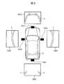
画像取得部1011は、自車周囲の環境を含む画像を取得する。画像取得部1011は、図2に示すように,自車10の周囲を撮像可能な位置に取り付けられたカメラ1001~1004から、自車周囲を撮影した画像1005~1008のうちいずれか1つ以上を取得する。本実施例においては、自車10の進行方向の情報に基づき、前進時は前方カメラ1001で撮像した画像1005を取得し、後進時は後方カメラ1004で撮像した画像1008を取得する。取得した画像は、2次元配列としてRAM上に記録される。以下、入力画像はIMGSRC[x][y]で表すものとする。x、yはそれぞれ画像の座標を示す。図2に示す各画像1005~1008は、自車10が駐車枠に前向き駐車したときの画像であり、駐車スペースの区画線Lが撮像されている。
The image acquisition unit 1011 acquires an image including the environment around the vehicle. As shown in FIG. 2, the image acquisition unit 1011 is one or more of the images 1005 to 1008 obtained by photographing the surroundings of the vehicle from the cameras 1001 to 1004 attached at positions where the surroundings of the vehicle 10 can be imaged. To get In the present embodiment, based on the information on the traveling direction of the vehicle 10, an image 1005 captured by the front camera 1001 is acquired during forward movement, and an image 1008 captured by the rear camera 1004 is acquired during reverse travel. The acquired images are recorded on the RAM as a two-dimensional array. Hereinafter, the input image is represented by IMGSRC [x] [y]. x and y indicate coordinates of the image, respectively. Each of the images 1005 to 1008 shown in FIG. 2 is an image when the vehicle 10 is parked forward in the parking frame, and the dividing line L of the parking space is captured.
特徴点位置計測部1021は、画像から特徴点を抽出し、特徴点を時系列追跡した画像上の動きに基づいて特徴点の三次元位置を計測する。つまり、特徴点位置計測部1021では、入力画像IMGSRC[x][y]から特徴点FP[p]を抽出し、その特徴点FP[p]を時系列追跡した画像上の動き(特徴点の時系列変化)に基づいて、特徴点の三次元位置として、自車10から特徴点FP[p]までの距離を計測する。特徴点位置計測部1021は、入力画像IMGSRC[x][y]から特徴点FP[p]を検出し、時系列に追跡することにより各特徴点の画像座標テーブルFPI[p]から3次元距離テーブルFPW[p]を計測する。ここで、FPI[p]は画像座標(x、y)、FPW[p]は自車後輪車軸を原点とする世界座標(x、y、z)の要素を持つテーブルの1次元配列であり、pは複数検出した場合のIDを表す。処理の詳細は後述する。
The feature point position measurement unit 1021 extracts feature points from the image, and measures the three-dimensional position of the feature points based on the movement on the image in which the feature points are tracked in time series. That is, the feature point position measurement unit 1021 extracts the feature point FP [p] from the input image IMGSRC [x] [y], and moves on the image in which the feature point FP [p] is traced in time series (feature point Based on the time-series change, the distance from the vehicle 10 to the feature point FP [p] is measured as the three-dimensional position of the feature point. The feature point position measurement unit 1021 detects feature points FP [p] from the input image IMGSRC [x] [y] and tracks them in time series to obtain a three-dimensional distance from the image coordinate table FPI [p] of each feature point. Measure the table FPW [p]. Here, FPI [p] is an image coordinate (x, y), and FPW [p] is a one-dimensional array of a table having elements of world coordinates (x, y, z) whose origin is the rear wheel axle of the vehicle. , P represents an ID when a plurality of detected. Details of the process will be described later.
特徴点足元位置算出部1031は、特徴点の三次元位置から特徴点の足元位置を算出する。つまり、特徴点足元位置算出部1031では、特徴点FP[p]の世界座標FPW[p]からカメラの設置高さや角度といったカメラ幾何情報を用いて、特徴点FP[p]の足元位置FPW0[p]を算出する。ここで、FPW0[p]は世界座標(x、y、0)の要素を持つテーブルの1次元配列であり、pは複数検出した場合のIDを表す。処理の詳細は後述する。特徴点の足元位置とは、特徴点の位置から鉛直方向に下げた路面上の位置をいう。
The feature point and foot position calculation unit 1031 calculates the foot position of the feature point from the three-dimensional position of the feature point. That is, the feature point foot position calculation unit 1031 uses the camera geometric information such as the camera installation height and angle from the world coordinates FPW [p] of the feature point FP [p] to the foot position FPW0 [of the feature point FP [p]. p] is calculated. Here, FPW 0 [p] is a one-dimensional array of a table having an element of world coordinates (x, y, 0), and p represents an ID in the case of detecting a plurality of elements. Details of the process will be described later. The foot position of the feature point refers to the position on the road surface lowered in the vertical direction from the position of the feature point.
路面領域推定部1041は、画像から画像のテクスチャの類似度を用いて、自車が走行可能な路面領域を推定する。つまり、路面領域推定部1041では、入力画像IMGSRC[x][y]から、画像のテクスチャ情報を解析し、路面領域を抽出する。情報の持ち方は様々あるが、本実施例においては、1グリッド5cm程度で自車後輪車軸中心を原点とするグリッドマップGRD[x][y]を前後左右10m程度の範囲で用意し、路面領域ほど「1」、非路面領域ほど「0」となるような推定値をもたせるものとする。処理の詳細は後述する。
The road surface area estimation unit 1041 estimates a road surface area on which the vehicle can travel using the similarity of the texture of the image from the image. That is, the road surface area estimation unit 1041 analyzes the texture information of the image from the input image IMGSRC [x] [y] to extract the road surface area. There are various ways of holding information, but in the present embodiment, a grid map GRD [x] [y] having an origin of the rear wheel axle of one vehicle is prepared in a range of about 10 m in front and rear, around 5 cm in 1 grid, It is assumed that the road surface area has an estimated value of “1”, and the non-road surface area has an estimated value of “0”. Details of the process will be described later.
障害物判定部1051は、特徴点の足元位置と推定した路面領域とを比較し、足元位置が推定した路面領域に含まれない特徴点を自車周囲の静止した障害物の特徴点であると判定する。つまり、障害物判定部1051では、特徴点FP[p]の足元位置FPW0[p]=(x、y、0)の座標と路面領域推定値を格納したグリッドGRD[x][y]を比較し、特徴点の足元位置が路面領域に含まれている特徴点は除去し、路面領域に含まれていない特徴点を残した障害物特徴点OFP[q]を生成する。処理の詳細は後述する。
The obstacle determination unit 1051 compares the foot position of the feature point with the estimated road surface area, and determines that the feature point not included in the road surface area where the foot position is estimated is the feature point of the stationary obstacle around the vehicle. judge. That is, the obstacle determination unit 1051 compares the coordinates of the foot position FPW0 [p] = (x, y, 0) of the feature point FP [p] with the grid GRD [x] [y] storing the road surface area estimated value. The feature point whose foot position is included in the road surface area is removed, and an obstacle feature point OFP [q] is generated in which the feature points not included in the road surface area are left. Details of the process will be described later.
[特徴点位置計測部1021]
つぎに、図3、4を用いて、特徴点位置計測部1021における処理の内容について説明する。 [Feature point position measurement unit 1021]
Next, the contents of processing in the feature pointposition measurement unit 1021 will be described using FIGS. 3 and 4.
つぎに、図3、4を用いて、特徴点位置計測部1021における処理の内容について説明する。 [Feature point position measurement unit 1021]
Next, the contents of processing in the feature point
図3は、特徴点位置計測部1021の処理の流れを示したフローチャートである。また、図4は、特徴点位置計測部1021の処理の説明図である。
FIG. 3 is a flowchart showing the process flow of the feature point position measurement unit 1021. FIG. 4 is an explanatory diagram of processing of the feature point position measurement unit 1021.
特徴点位置計測部1021は、入力画像IMGSRC[x][y]に対して実施する。
The feature point position measurement unit 1021 executes the input image IMGSRC [x] [y].
まず、ステップS301にて、現在画像である入力画像IMGSRC[x][y]から特徴点FPI[p]を抽出する。特徴点FPI[p]の抽出は、Harrisコーナー等公知の方法を用いる。その結果、各特徴点に対して画像座標が得られる。
First, in step S301, the feature point FPI [p] is extracted from the input image IMGSRC [x] [y] that is the current image. Extraction of feature point FPI [p] uses a known method such as Harris corner. As a result, image coordinates are obtained for each feature point.
つぎに、ステップS302にて、同じカメラから取得された、所定時刻前の過去画像IMGSRC_Pを取得する。
Next, in step S302, a past image IMGSRC_P before a predetermined time acquired from the same camera is acquired.
つぎに、ステップS303にて、現在画像と過去画像からオプティカルフローを算出する。ここでは、現在画像IMGSRC上における各特徴点FPI[p]の過去画像IMGSRC_P上の対応位置を、オプティカルフロー法により算出し、各特徴点の移動ベクトルFP_VX[p]、FP_VY[p]を取得する。オプティカルフローは、Lucas-Kanade法等、公知の方法を用いる。
Next, in step S303, an optical flow is calculated from the current image and the past image. Here, the corresponding position on the past image IMGSRC_P of each feature point FPI [p] on the current image IMGSRC is calculated by the optical flow method, and the movement vectors FP_VX [p] and FP_VY [p] of each feature point are acquired. . The optical flow uses known methods such as the Lucas-Kanade method.
そして、ステップS304にて、オプティカルフローから3次元情報FPW[p]を算出する。ここでは、特徴点FPI[p]および移動ベクトルFP_VX[p]、FP_VY[p]を用いて、各特徴点FPI[p]の自車周囲における3次元位置を算出する。算出方法は、公知の手段を用いる。本実施例においては、画像上の移動ベクトルと、CANにより取得した自車位置DRC[t]およびDRC[t-1]を用いて算出した自車移動量を用いる。ここで、tは処理のタイミングを表す記号であり、自車移動量DRC[t]は、自車後輪車軸中心を原点とする座標系におけるX、Y、ヨー角である。自車位置DRC[t]およびDRC[t-1]より、X、Y、ヨー角の移動量が得られる。
Then, in step S304, three-dimensional information FPW [p] is calculated from the optical flow. Here, the three-dimensional position of each feature point FPI [p] around the vehicle is calculated using the feature point FPI [p] and the movement vectors FP_VX [p] and FP_VY [p]. The calculation method uses a known means. In this embodiment, the movement vector on the image and the movement amount of the vehicle calculated using the vehicle positions DRC [t] and DRC [t-1] acquired by CAN are used. Here, t is a symbol representing processing timing, and the own vehicle movement amount DRC [t] is an X, Y, and yaw angle in a coordinate system having the center of the rear wheel axle of the own vehicle as the origin. From the own vehicle positions DRC [t] and DRC [t-1], movement amounts of X, Y, and yaw angle can be obtained.
最後に、ステップS305にて、各特徴点の相対座標を取得する処理を行う。ここでは、各特徴点の3次元位置を車両の後輪車軸中心を原点とする座標系に変換し、距離テーブルFPW[p]として格納する。
Finally, in step S305, processing is performed to acquire relative coordinates of each feature point. Here, the three-dimensional position of each feature point is converted into a coordinate system having the center of the rear wheel axle of the vehicle as an origin, and stored as a distance table FPW [p].
図4(a)に示すように、過去の自車位置DRC[t-1]と現在の自車位置DRC[t]が変化することにより視差が生まれ、距離を計測することができる。図4(a)に示す例では、自車10がt-1時点からt時点までの間に距離dだけ進むことによって生じた視差に基づいて駐車車両20までの距離Yが計測される。画像の特徴点それぞれの距離を計測するため、たとえば駐車車両20に対して計測した結果は、図4(b)に示すように、複数の点21として計測される。
As shown in FIG. 4A, a parallax is generated by changing the past vehicle position DRC [t-1] and the current vehicle position DRC [t], and the distance can be measured. In the example shown in FIG. 4A, the distance Y to the parked vehicle 20 is measured based on the parallax generated as the vehicle 10 travels by the distance d from time t-1 to time t. In order to measure the distance of each of the feature points of the image, for example, the measurement result of the parked vehicle 20 is measured as a plurality of points 21 as shown in FIG. 4 (b).
[特徴点足元位置算出部1031]
つぎに、足元位置算出部1031における処理の内容について説明する。 [Feature point foot position calculation unit 1031]
Next, the contents of processing in the footposition calculation unit 1031 will be described.
つぎに、足元位置算出部1031における処理の内容について説明する。 [Feature point foot position calculation unit 1031]
Next, the contents of processing in the foot
本実施例においては、2つの方法について説明する。
In the present embodiment, two methods will be described.
まず、一つ目の方法(一番目の方法)は、単純に距離テーブルFPW[p]を距離テーブルFPW0[p]=(x、y、z)へコピーし、距離テーブルFPW0[p]のz=0とする方法である。
First, the first method (the first method) simply copies the distance table FPW [p] to the distance table FPW0 [p] = (x, y, z), and z of the distance table FPW0 [p] It is a method to make it = 0.
そして、二つ目の方法(二番目の方法)は、特徴点の3次元位置から足元位置を算出する際に、路面高さを実際の路面よりも高い位置に設定して画像座標を算出し、画像座標の路面高さ位置における3次元座標を算出する方法である。この二番目の方法について、図5を用いて説明する。
Then, in the second method (the second method), when calculating the foot position from the three-dimensional position of the feature point, the road surface height is set to a position higher than the actual road surface to calculate the image coordinates. , And a method of calculating three-dimensional coordinates at a road surface height position of image coordinates. This second method will be described with reference to FIG.
図5は、足元位置算出部1031の処理の流れを示したフローチャートである。
FIG. 5 is a flowchart showing the process flow of the foot position calculation unit 1031.
まず、ステップS501にて、距離テーブルFPW[p]=(x、y、z)を距離テーブルFPW0T[p]=(x、y、z)へコピーする。
First, in step S501, the distance table FPW [p] = (x, y, z) is copied to the distance table FPW0T [p] = (x, y, z).
つぎに、ステップS502にて、距離テーブルFPW0T[p]の高さzを、実際の路面より高い値「Hv」に設定する。
Next, in step S502, the height z of the distance table FPW0T [p] is set to a value "Hv" higher than the actual road surface.
つぎに、ステップS503にて、距離テーブルFPW0T[p]から画像座標テーブルFPI0[p]を算出する。算出には、予め登録されているカメラの設置高さ、設置角度やレンズの歪テーブルといったカメラ幾何情報を用いる。カメラ幾何情報を用いて、世界座標から画像座標を算出する処理は公知の技術であるため詳細な説明は割愛する。
Next, in step S503, the image coordinate table FPI0 [p] is calculated from the distance table FPW0T [p]. For the calculation, camera geometric information such as the installation height of the camera registered in advance, the installation angle, and the distortion table of the lens are used. A process of calculating image coordinates from world coordinates using camera geometric information is a known technique, and therefore detailed description will be omitted.
そして、ステップS504にて、カメラ幾何情報を用いて、画像座標テーブルFPI0[p]の位置における、路面高さ(z=0)における距離テーブルFPW0[p]=(x、y、0)を算出する。
Then, in step S 504, using camera geometric information, distance table FPW 0 [p] = (x, y, 0) at the road surface height (z = 0) at the position of image coordinate table FPI 0 [p] is calculated. Do.
足元位置の算出方法として、上記した一番目の方法と二番目の方法のどちらを用いるべきかは、自車10のカメラの設置高さに応じて選択できる。また、二番目の方法の高さHvは、仕向け地や自車の車種によって値を変えてもよい。さらに、機械学習による識別器を用いて画像内の車両の種類を識別し、その種類に応じて変えてもよい。機械学習による車両の検出や車種の判定方法は公知技術のため、ここでは説明を割愛する。図6は、自車のカメラで他の車両を撮像している状況を模式的に示す図であり、図6(a)は一番目の方法を示し、図6(b)は二番目の方法を示している。
Whether to use the first method or the second method described above as the method of calculating the foot position can be selected according to the installation height of the camera of the vehicle 10. Also, the height Hv of the second method may be changed depending on the destination and the type of vehicle. Furthermore, a machine learning identifier may be used to identify the type of vehicle in the image and change according to the type. Description of vehicle detection and vehicle type determination methods by machine learning will be omitted here because they are known techniques. FIG. 6 is a view schematically showing a situation in which another camera is imaged by the camera of the own vehicle, and FIG. 6 (a) shows the first method, and FIG. 6 (b) shows the second method Is shown.
図6(a)に示すように、低く設置されたカメラを用いて、他の車両20を対象に特徴点位置計測部1021と路面領域推定部1041による処理を実行すると、車のバンパーは路面よりも高い位置にあるため、路面領域推定部1041により推定した路面領域がバンパーの下まで回りこんでしまい、特徴点位置計測部1021により得られる距離よりも広い範囲で路面領域が検出される。そのため、図6(b)に示すように、車のバンパーの高さHvの位置で一旦画像座標に変換し、その画像座標の路面高さ(z=0)における距離を求めることで、距離テーブルFPW0[p]と路面領域が重複しないようにすることができる。
As shown in FIG. 6A, when processing is performed by the feature point position measurement unit 1021 and the road surface area estimation unit 1041 for another vehicle 20 using a camera installed low, the bumper of the car is better than the road surface. Because the road surface area estimated by the road surface area estimation unit 1041 turns to under the bumper, the road surface area is detected in a wider range than the distance obtained by the feature point position measurement unit 1021. Therefore, as shown in FIG. 6B, the distance table is temporarily converted into image coordinates at the position of the height Hv of the bumper of the car, and the distance at the road surface height (z = 0) of the image coordinates is obtained. It is possible to prevent the road surface area from overlapping with FPW0 [p].
つまり、一番目の方法では、図6(a)に示すように、路面領域推定部104で推定した路面領域内に、特徴点足元位置算出部1031で算出した足元位置が入り込んでしまうので、障害物判定部1051によって、その特徴点は誤検出されたものと判断されて除去されるおそれがある。これに対して、二番目の方法では、図6(b)に示すように、特徴点から下方に所定長さだけ離れた位置にバンパーの下縁が存在するとみなし、かかる位置、換言すると、足元位置から路面から高さHvの位置を、障害物判定部1051の障害物判定に用いる。障害物判定部1051では、カメラと足元位置から路面から高さHVの位置との間を結ぶ線を路面まで延長した位置が、推定した路面領域の端縁近傍に位置している場合には、障害物の特徴点として残す処理を行う。
That is, in the first method, as shown in FIG. 6A, the foot position calculated by the feature point foot position calculation unit 1031 is embedded in the road surface area estimated by the road surface area estimation unit 104. The object determination unit 1051 may determine that the feature point is erroneously detected and may be removed. On the other hand, in the second method, as shown in FIG. 6 (b), it is considered that the lower edge of the bumper exists at a position separated by a predetermined length downward from the feature point, and such position, in other words, the foot The position from the position to the height Hv from the road surface is used for the obstacle determination of the obstacle determination unit 1051. In the obstacle judging unit 1051, if a position obtained by extending the line connecting the camera and the foot position to the position of height HV from the foot surface to the road surface is near the edge of the estimated road surface area, Perform processing to leave as feature points of obstacles.
[路面領域推定部1041]
つぎに、図7,8,9を用いて、路面領域推定部1041における処理の内容について説明する。 [Road surface area estimation unit 1041]
Next, the contents of processing in the road surfacearea estimation unit 1041 will be described using FIGS.
つぎに、図7,8,9を用いて、路面領域推定部1041における処理の内容について説明する。 [Road surface area estimation unit 1041]
Next, the contents of processing in the road surface
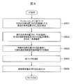
図7は、路面領域推定部1041の処理の流れを示したフローチャートである。
FIG. 7 is a flowchart showing the process flow of the road surface area estimation unit 1041.
路面領域推定部1041は、入力画像IMGSRC[x][y]に対して実施する。画像から路面領域を推定する方法は、たとえば機械学習を用いた方法や、画像内の類似度を用いた方法等様々あるが、本実施例では、特徴点位置計測部1021の結果を用いて実施する方法を用いる。
The road surface area estimation unit 1041 performs the input image IMGSRC [x] [y]. There are various methods of estimating the road surface area from the image, for example, a method using machine learning, a method using the similarity in the image, etc. In this embodiment, the method is implemented using the result of the feature point position measurement unit 1021 Method is used.
まず、ステップS701にて、入力画像IMGSRC[x][y]を複数の局所領域R[r]に分割する。
First, in step S701, the input image IMGSRC [x] [y] is divided into a plurality of local regions R [r].
つぎに、ステップS702にて、特徴点から計測された距離テーブルFPW[p]=(x、y、z)のうち高さが路面高さの範囲(thZrmin、thZrmax)の範囲内の特徴点を抽出し、その特徴点が属する局所領域R[r]のIDのテーブルrd[d]を抽出する。
Next, in step S702, among the distance tables FPW [p] = (x, y, z) measured from the feature points, the feature points within the range of the road surface height (thZrmin, thZrmax) are selected. The table rd [d] of the ID of the local region R [r] to which the feature point belongs is extracted.
以下、ステップS703からS705まで、rd[d]についてd=0からDまで繰り返し処理を行う。
Hereinafter, the process is repeatedly performed from step S703 to step S705, and from d = 0 to D for rd [d].
まず、ステップS703にて、路面高さの範囲内の特徴点が属する局所領域R[rd[d]]から、画像のヒストグラム情報Hst1を取得する。
First, in step S703, histogram information Hst1 of an image is acquired from a local region R [rd [d]] to which a feature point within the range of road surface heights belongs.
つぎに、ステップS704にて、路面高さの範囲内の特徴点が属する局所領域R[rd[d]]近傍の局所領域R[r’]について、以下ステップS704,S705の処理を行う。近傍の判定は、たとえば局所領域R[rd[d]]と局所領域R[r’]の中心間の距離が閾値thRDist以下である領域とする。
Next, in step S704, the processing in steps S704 and S705 is performed on the local region R [r '] in the vicinity of the local region R [rd [d]] to which the feature point in the range of road surface heights belongs. The determination of the vicinity is, for example, a region in which the distance between the centers of the local region R [rd [d]] and the local region R [r '] is equal to or less than the threshold thRDist.
まず、ステップS704にて、局所領域R[r’]のヒストグラム情報Hst2を取得する。
First, in step S704, histogram information Hst2 of the local region R [r '] is acquired.
そして、ステップS705にて、ヒストグラムHst1とHst2の類似度Matchを算出し、類似度が閾値thMatch以上であれば、その局所領域R[r’]のID=r’をテーブルrdm[dm]へ登録する。
Then, in step S705, the similarity Match between the histograms Hst1 and Hst2 is calculated, and if the similarity is equal to or greater than the threshold thMatch, ID = r 'of the local region R [r'] is registered in the table rdm [dm] Do.
すべてのr’に対する処理が終了したら、次のrd[d]を選択し、ステップS703へ戻る。
When the processing for all r's is completed, the next rd [d] is selected, and the process returns to step S703.
すべてのrd[d]に対して処理を終了したらステップS706へ移動し、rd[d]およびrdm[dm]に所属するすべての局所領域R[rd[d]]、R[rdm[dm]]を、画像内の路面領域推定瞬間値RDI[t]として抽出する。
When the process is completed for all rd [d], the process moves to step S706, and all local areas R [rd [d]], R [rdm [dm]] belonging to rd [d] and rdm [dm] are processed. Is extracted as a road surface area estimated instantaneous value RDI [t] in the image.
さらに、ステップS707にて、カメラ幾何情報を用いて、路面領域の境界を世界座標の路面推定瞬間値RDT[x][y]へ変換し、時系列処理を行う。
Further, in step S 707, the boundary of the road surface area is converted into the road surface estimated instantaneous value RDT [x] [y] of the world coordinates using camera geometric information, and time series processing is performed.
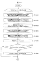
ステップS707の時系列処理について、図8,9を用いて説明する。図8は処理のフロー、図9は時系列処理の説明図である。
The time-series process of step S 707 will be described using FIGS. FIG. 8 is a flow of processing, and FIG. 9 is an explanatory view of time series processing.
まず、ステップS801にて、デッドレコニング情報に基づき、今回の自車位置DRC[t]と前回の自車位置DRC[t-1]を取得し、今回の自車位置DRC[t]を基準とする前回の自車位置DRC_P[t]を算出する。図9(a)はその例である。図9(a)では、今回の自車位置を実線で示し、前回の自車位置を破線で示している。
First, in step S801, based on the dead reckoning information, the current vehicle position DRC [t] and the previous vehicle position DRC [t-1] are acquired, and the current vehicle position DRC [t] is used as a reference. The previous vehicle position DRC_P [t] to be calculated is calculated. FIG. 9A is an example thereof. In FIG. 9A, the current vehicle position is indicated by a solid line, and the previous vehicle position is indicated by a broken line.
つぎに、ステップS802にて、前回の自車位置DRC_P[t]を基準とし、前回の路面領域推定結果GRDz1[x][y]を展開し、全体から一定値を減算する。図9(b)はその例である。図9(b)には、前回の路面領域推定結果151を破線で示している。
Next, in step S802, based on the previous vehicle position DRC_P [t], the previous road surface area estimation result GRDz1 [x] [y] is expanded, and a constant value is subtracted from the whole. FIG. 9 (b) is an example thereof. In FIG. 9B, the previous road surface area estimation result 151 is indicated by a broken line.
つづいて、ステップS803にて、今回の自車位置DRC[t]を基準とし、今回の路面領域推定瞬間値RDT[t][x][y]を展開する。図9(c)はその例である。図9(c)には、今回の路面領域推定瞬間値152を実線で示している。
Subsequently, in step S803, the road surface area estimated instantaneous value RDT [t] [x] [y] is developed on the basis of the current vehicle position DRC [t]. FIG. 9C shows an example. In FIG. 9C, the current road surface area estimated instantaneous value 152 is indicated by a solid line.
そして、ステップS804にて、前回の路面領域推定結果RDT[t-1][x][y]と今回の路面領域推定瞬間値RDT[t][x][y]を加算する。図9(d)はその例である。図9(d)では、前回と今回の路面領域推定瞬間値の重複領域153をハッチングで示している。
Then, in step S804, the previous road surface area estimation result RDT [t-1] [x] [y] and the current road surface area estimated instantaneous value RDT [t] [x] [y] are added. FIG. 9 (d) is an example thereof. In FIG. 9D, the overlapping area 153 of the previous and current road surface area estimation instantaneous values is indicated by hatching.
さらに、ステップS805にて、重複領域を今回の路面領域推定結果GRD[x][y]として出力し、同時に、今回の路面領域推定結果を前回の路面領域推定結果GRDz1[x][y]へコピーする。
[障害物判定部1051]つぎに、図10、図11を用いて障害物判定部1051の処理の内容について説明する。 Furthermore, in step S805, the overlapping area is output as the road surface area estimation result GRD [x] [y] of this time, and at the same time, the current road surface area estimation result is output to the previous road surface area estimation result GRDz1 [x] [y]. make a copy.
[Obstacle Determination Unit 1051] Next, the contents of the process of theobstacle determination unit 1051 will be described with reference to FIGS. 10 and 11. FIG.
[障害物判定部1051]つぎに、図10、図11を用いて障害物判定部1051の処理の内容について説明する。 Furthermore, in step S805, the overlapping area is output as the road surface area estimation result GRD [x] [y] of this time, and at the same time, the current road surface area estimation result is output to the previous road surface area estimation result GRDz1 [x] [y]. make a copy.
[Obstacle Determination Unit 1051] Next, the contents of the process of the
図10は障害物判定部1051の処理の流れを示したフローチャートである。
FIG. 10 is a flowchart showing the process flow of the obstacle judging unit 1051.
処理は、ステップS10001からS1003まで、特徴点IDであるp=0からPまで繰り返し処理を行う。
The processing is repeatedly performed from step S10001 to step S1003 and feature point IDs p = 0 to P.
まず、ステップS10001にて特徴点FP[p]の足元座標FPW0[p]を取得する。
First, in step S10001, foot coordinates FPW0 [p] of the feature point FP [p] are acquired.
つぎに、ステップS10002にて足元座標FPW0[p]を路面領域推定結果GRD[x][y]へ投影し、足元座標を確認し、足元座標FPW0[p]の路面領域推定値が閾値thRoad未満、すなわち路面ではなかったら、ステップS10003へ移動し、障害物特徴点OFP[q]へ登録する。
Next, the foot coordinates FPW0 [p] are projected onto the road surface area estimation result GRD [x] [y] in step S10002, and the foot coordinates are confirmed, and the road surface area estimated value of the foot coordinates FPW0 [p] is less than the threshold thRoad That is, if it is not a road surface, the process moves to step S10003 and is registered to the obstacle feature point OFP [q].
上記処理をすべての特徴点FP[p]について実施する。
The above process is performed for all feature points FP [p].
一方、図11は障害物判定部1051の異なる処理の流れを示したフローチャートである。
On the other hand, FIG. 11 is a flowchart showing a flow of different processing of the obstacle judging unit 1051.
処理は、ステップS11001からS11009まで、特徴点IDであるp=0からPまで繰り返し処理を行う。
The processing is repeatedly performed from step S11001 to step S11009 from p = 0 to P which is a feature point ID.
まず、ステップS11001にて、特徴点FP[p]の世界座標FPW[p]と、p以外のすべての世界座標FPW[p’]との距離を比較し、半径thAround以内の特徴点の合計数SumAroundを算出する。本実施例では、距離算出には世界座標(x、y、z)のうち、(x、y)のみを用いる。
First, in step S11001, the distance between world coordinates FPW [p] of feature point FP [p] and all world coordinates FPW [p '] except p is compared, and the total number of feature points within radius thAround Calculate SumAround. In the present embodiment, only (x, y) of world coordinates (x, y, z) is used for distance calculation.
つぎに、ステップS11002にて、合計数SumAroundと閾値thSumFewを比較し、合計数SumAroundが少なければステップS11004へ行く。そうでなければ、ステップS11005へ行き、合計数SumAroundと閾値thSumManyを比較し、合計数SumAroundが多ければステップS11005へ行く。
そうでなければステップS11006へ行く。 Next, in step S11002, the total number SumAround and the threshold thSumFew are compared, and if the total number SumAround is small, the process proceeds to step S11004. If not, the flow goes to step S11005, and the total number SumAround is compared with the threshold thSumMony, and if the total number SumAround is large, the flow goes to step S11005.
If not, the process goes to step S11006.
ステップS11004からS11006では、後段で利用する閾値thRoadを設定する。ステップS11004では、閾値thRoad=thRoadFewとする。ステップS11005では、閾値thRoad=thRoadManyとする。ステップS11006では、閾値thRoad=thRoadNormalとする。
In steps S11004 to S11006, a threshold thRoad to be used later is set. In step S11004, the threshold thRoad = thRoadFew is set. In step S11005, the threshold thRoad = thRoadMany. In step S11006, the threshold thRoad = thRoadNormal is set.
ここで、thRoadFew<thRoadNormal<thRoadManyである。
Here, it is thRoadFew <thRoadNormal <thRoadMany.
つぎに、ステップS11007にて、特徴点FP[p]の足元座標FPW0[p]を取得する。
Next, in step S11007, foot coordinates FPW0 [p] of the feature point FP [p] are acquired.
つぎに、ステップS11008にて足元座標FPW0[p]を路面領域推定結果GRD[x][y]へ投影し、足元座標を確認し、足元座標FPW0[p]の路面領域推定値が閾値thRoad未満、すなわち路面ではなかったら、ステップS10003へ移動し、障害物特徴点OFP[q]へ登録する。
Next, in step S11008, foot coordinates FPW0 [p] are projected onto road surface area estimation result GRD [x] [y], and foot coordinates are confirmed, and the road surface area estimated value of foot coordinates FPW0 [p] is less than threshold thRoad That is, if it is not a road surface, the process moves to step S10003 and is registered to the obstacle feature point OFP [q].
上記処理をすべての特徴点FP[p]について実施する。
The above process is performed for all feature points FP [p].
特徴点足元位置算出特徴点足元位置算出の際に部1031にて説明したように、路面高さよりも高い位置で一旦画像座標を求め、その点が路面高さに存在するものと仮定する処理により、カメラの設置高さが低い場合に対象物体が車両のバンパーのように空中に浮いている場合であっても適切に障害物を障害物と判定することができる。
Feature point foot position calculation Feature point foot point position calculation As described in the section 1031, the image coordinates are once obtained at a position higher than the road surface height, and it is assumed that the point exists at the road surface height. Even when the target object is floating in the air like a bumper of a vehicle when the installation height of the camera is low, an obstacle can be appropriately determined as an obstacle.
また、障害物判定部1051で説明したように、特徴点の密集度に応じてその特徴点の閾値を変化させることで、はずれ値のように特徴点が孤立して出力されているようなものを除去しやすく設定することができる。
In addition, as described in the obstacle determination unit 1051, by changing the threshold value of the feature points according to the density of the feature points, the feature points are output so as to be isolated like outliers. Can be set easily.
本実施の形態の車載用外界認識装置1000によれば、自車周囲の環境を含む画像から特徴点を抽出し、特徴点を時系列追跡した画像上の動きに基づいて特徴点の3次元位置を計測し、特徴点の3次元位置から画像上の足元位置を算出する処理を行う。そして、画像のテクスチャの類似度を用いて自車が走行可能な路面領域を画像内から抽出し、特徴点の足元位置が路面領域に含まれないと判定された特徴点を信頼度が高いと判定し、特徴点の足元位置が路面領域に含まれていると判定された特徴点を信頼性が低いと判定する処理を行う。信頼性の高い特徴点は、自車周囲の静止した障害物の特徴点である可能性が高い。
According to the on-vehicle external environment recognition apparatus 1000 of the present embodiment, the feature points are extracted from the image including the environment around the vehicle, and the three-dimensional position of the feature points based on the movement on the image in which the feature points are traced in time series. To calculate the foot position on the image from the three-dimensional position of the feature point. Then, the road surface area on which the vehicle can travel is extracted from the image using the similarity of the texture of the image, and the feature point determined not to be included in the road surface area is highly reliable. A process of determining and determining that the reliability is low is performed on the feature point determined to be included in the road surface area at the foot of the feature point. A reliable feature point is likely to be a feature point of a stationary obstacle around the vehicle.
一方、特徴点の足元位置が路面領域に含まれている特徴点は、自車周囲の静止した障害物の特徴点である可能性が低く、例えば移動体による誤検知であることが予想される。車載用外界認識装置1000は、計測した特徴点の足元位置と路面領域との重複を用いて、特徴点の確からしさを判定するので、特徴点の足元位置とエッジの位置とが異なっていたり、足下のエッジの観測が難しい場合であっても、その影響を受けない。また、偶然存在するエッジによる誤判定も発生しない。
On the other hand, the feature point whose footpoint position of the feature point is included in the road surface area is unlikely to be the feature point of a stationary obstacle around the vehicle, for example, it is expected to be false detection by a moving object . Since the in-vehicle external environment recognition apparatus 1000 determines the likelihood of a feature point using the overlap between the foot position of the measured feature point and the road surface area, the foot position of the feature point is different from the position of the edge, Even if it is difficult to observe the edge of the foot, it is not affected. In addition, there is no occurrence of an erroneous determination due to an edge that is present by chance.
<第二実施の形態>
つぎに、本発明の車載用外界認識装置の第二実施の形態について、以下に図面を用いて説明する。 Second Embodiment
Next, a second embodiment of the on-vehicle external environment recognition apparatus of the present invention will be described below using the drawings.
つぎに、本発明の車載用外界認識装置の第二実施の形態について、以下に図面を用いて説明する。 Second Embodiment
Next, a second embodiment of the on-vehicle external environment recognition apparatus of the present invention will be described below using the drawings.
図12は、第二実施の形態における車載用外界認識装置2000の構成を示すブロック図である。なお、以下の説明では、上述の第一実施の形態における車載用外界認識装置1000と異なる箇所のみ詳述し、同様の箇所には同一の番号を付してその詳細な説明を省略する。
FIG. 12 is a block diagram showing a configuration of an on-vehicle external world recognition apparatus 2000 in the second embodiment. In the following description, only portions different from the in-vehicle external environment recognition apparatus 1000 in the first embodiment described above will be described in detail, and the same portions will be denoted by the same reference numerals and detailed description thereof will be omitted.
本実施の形態において特徴的なことは、障害物情報取得部2111と空間情報取得部2112を有し、さらに障害物情報取得部2111から得られた障害物情報を用いた障害物方位算出部2131を有しており、これらが第一実施の形態とは異なる処理内容となる障害物判定部2051に入力されていることである。
What is characteristic in the present embodiment is an obstacle direction calculation unit 2131 having an obstacle information acquisition unit 2111 and a space information acquisition unit 2112 and further using obstacle information obtained from the obstacle information acquisition unit 2111. , And these are input to the obstacle judging unit 2051 which has processing contents different from those in the first embodiment.
車載用外界認識装置2000は、自動車に搭載されるカメラ装置内、もしくは統合コントローラ内等に組み込まれ、カメラ1001~1004で撮影した画像内から外界を認識するためのものであり、本実施の形態では、自車周囲の障害物を認識するように構成されている。
The on-vehicle external world recognition apparatus 2000 is incorporated in a camera apparatus mounted on a car, in an integrated controller, etc., and is for recognizing the external world from the images taken by the cameras 1001 to 1004. So, it is configured to recognize obstacles around the vehicle.
車載用外界認識装置2000は、CPUやメモリ、I/O等を有するコンピュータによって構成されており、所定の処理がプログラミングされて、あらかじめ定められた周期で繰り返し処理を実行する。
The on-vehicle external world recognition device 2000 is configured by a computer having a CPU, a memory, an I / O, etc., and a predetermined process is programmed to repeatedly execute the process in a predetermined cycle.
画像取得部1011は、自車周囲の環境を含む画像を取得する。画像取得部1011は、図2に示すように,自車10の周囲を撮像可能な位置に取り付けられたカメラ1001~1004から、自車周囲を撮影した画像1005~1008のうちいずれか1つ以上を取得する。本実施例においては、自車10の進行方向の情報に基づき、前進時は前方カメラ1001で撮像した画像1005を取得し、後進時は後方カメラ1004で撮像した画像1008を取得する。取得した画像は入力画像はIMGSRC[x][y]としてRAM上に記録される。第一実施例のものと同様のため、説明は省略する。
The image acquisition unit 1011 acquires an image including the environment around the vehicle. As shown in FIG. 2, the image acquisition unit 1011 is one or more of the images 1005 to 1008 obtained by photographing the surroundings of the vehicle from the cameras 1001 to 1004 attached at positions where the surroundings of the vehicle 10 can be imaged. To get In the present embodiment, based on the information on the traveling direction of the vehicle 10, an image 1005 captured by the front camera 1001 is acquired during forward movement, and an image 1008 captured by the rear camera 1004 is acquired during reverse travel. The acquired image is recorded on the RAM as IMGSRC [x] [y]. The description is omitted because it is similar to that of the first embodiment.
特徴点位置計測部1021は、入力画像IMGSRC[x][y]から特徴点FP[p]を検出し、時系列に追跡することにより各特徴点の画像座標テーブルFPI[p]から3次元距離テーブルFPW[p]を計測する。第一実施例のものと同様のため、説明は省略する。
The feature point position measurement unit 1021 detects feature points FP [p] from the input image IMGSRC [x] [y] and tracks them in time series to obtain a three-dimensional distance from the image coordinate table FPI [p] of each feature point. Measure the table FPW [p]. The description is omitted because it is similar to that of the first embodiment.
特徴点足元位置算出部1031は、特徴点FP[p]の世界座標FPW[p]からカメラの設置高さや角度といったカメラ幾何情報を用いて、特徴点FP[p]の足元位置FPW0[p]を算出する。第一実施例のものと同様のため、説明は省略する。
The feature point and foot position calculation unit 1031 uses the camera geometric information such as the installation height and angle of the camera from the world coordinates FPW [p] of the feature point FP [p] to determine the foot position FPW0 [p] of the feature point FP [p]. Calculate The description is omitted because it is similar to that of the first embodiment.
路面領域推定部1041は、入力画像IMGSRC[x][y]から、画像のテクスチャ情報を解析し、路面領域を抽出する。情報の持ち方は様々あるが、本実施例においては、グリッドマップGRD[x][y]を用いるものとする。第一実施例のものと同様のため、説明は省略する。
The road surface area estimation unit 1041 analyzes the texture information of the image from the input image IMGSRC [x] [y] and extracts the road surface area. There are various ways of holding information, but in this embodiment, the grid map GRD [x] [y] is used. The description is omitted because it is similar to that of the first embodiment.
障害物情報取得部2111は、超音波センサから取得する障害物情報SOBJ[b]を取得する。ここでSOBJ[b]は自車後輪車軸中心を原点とする世界座標(x、y、z)の要素を持つテーブルの1次元配列であり、bは複数検知した場合のIDを表す。なお、本実施の形態では、自車周囲の障害物を検知するセンサの例として超音波センサを例に説明するが、音波や光線により検知できるセンサであればよく、例えば、自車に搭載されたレーザーレーダー、LIDAR、及び単眼カメラの少なくとも一つを用いてもよい。そして、障害物情報取得部2111は、障害物の情報を取得できるものであればよく、他車両から送信される情報や、駐車場などのインフラ設備から送信される情報を取得してもよい。
The obstacle information acquisition unit 2111 acquires obstacle information SOBJ [b] acquired from the ultrasonic sensor. Here, SOBJ [b] is a one-dimensional array of a table having elements of world coordinates (x, y, z) whose origin is the center of the rear wheel axle of the host vehicle, and b represents an ID when plural detections are made. In the present embodiment, an ultrasonic sensor will be described as an example of a sensor for detecting an obstacle around the host vehicle, but any sensor capable of detecting a sound wave or a light beam may be used. Laser radar, LIDAR, and at least one monocular camera may be used. Then, the obstacle information acquisition unit 2111 may be anything that can acquire information on an obstacle, and may acquire information transmitted from another vehicle or information transmitted from an infrastructure facility such as a parking lot.
空間情報取得部2112は、超音波センサにより検知した自車周囲の障害物の検知結果から自車が走行可能な空間の情報を取得する。具体的には、空間情報取得部2112は、超音波センサで検知した障害物の手前までの空きが確認できている空間情報SFS[f]を取得する。ここで、空間情報SFS[f]は各超音波センサから得られる、各センサから障害物までの空間情報、すなわち走行可能距離を距離で表すテーブルの一次元配列であり、fは超音波センサの取り付け数である。
The space information acquisition unit 2112 acquires information of a space in which the vehicle can travel from the detection results of obstacles around the vehicle detected by the ultrasonic sensor. Specifically, the space information acquisition unit 2112 acquires space information SFS [f] in which the space up to the front of the obstacle detected by the ultrasonic sensor can be confirmed. Here, the spatial information SFS [f] is a one-dimensional array of spatial information from each sensor to an obstacle obtained from each ultrasonic sensor, that is, a table representing the travelable distance by a distance, and f is an ultrasonic sensor It is the number of attachment.
障害物方位算出部2131は、障害物情報取得部2111から取得した障害物情報から、自車の左右の障害物の方位θL,θRを算出する。処理の詳細は後述する。
The obstacle direction calculation unit 2131 calculates the directions θL and θR of the left and right obstacles of the host vehicle from the obstacle information acquired from the obstacle information acquisition unit 2111. Details of the process will be described later.
障害物判定部2051は、特徴点の3次元位置から、所定の特徴点の周囲に存在する他の特徴点の密度を算出する空間特徴算出を行い、特徴点の密度の高さ、および、特徴点の画像内の足元位置と路面領域とを比較して、特徴点が障害物の特徴点であるか否かの判定を行う。具体的には、障害物判定部2051は、特徴点足元位置FPW0[p]、路面領域推定結果GRD[x][y]、さらに障害物情報SOBJ[b]、空間情報SFS[f]、障害物方位θL,θR、といった情報を活用して、障害物特徴点OFP[q]を生成する。処理の詳細は後述する。
The obstacle determination unit 2051 performs spatial feature calculation to calculate the density of another feature point existing around a predetermined feature point from the three-dimensional position of the feature point, and the height of the feature point density, and the feature The foot position in the image of the point and the road surface area are compared to determine whether the feature point is the feature point of the obstacle. Specifically, the obstacle judging unit 2051 detects the feature point foot position FPW0 [p], the road surface area estimation result GRD [x] [y], the obstacle information SOBJ [b], the space information SFS [f], and the obstacle. An obstacle feature point OFP [q] is generated by utilizing information such as the object orientations θL and θR. Details of the process will be described later.
[障害物方位算出部2131]
つぎに、図13を用いて、障害物方位算出部2131の処理の内容について説明する。 [Obstacle direction calculation unit 2131]
Next, contents of processing of the obstacledirection calculation unit 2131 will be described using FIG. 13.
つぎに、図13を用いて、障害物方位算出部2131の処理の内容について説明する。 [Obstacle direction calculation unit 2131]
Next, contents of processing of the obstacle
図13は障害物方位算出部2131の処理の流れを示したフローチャートである。障害物の方位を算出する方法は様々考えられるが、本実施例においては、サイドソナーによる自車側方の障害物検知情報を時系列に蓄積するサイドソナー情報をサイドソナーテーブルに蓄積して利用する方法を説明する。
FIG. 13 is a flowchart showing the process flow of the obstacle direction calculation unit 2131. There are various methods for calculating the direction of the obstacle, but in the present embodiment, side sonar information for accumulating obstacle detection information on the side of the vehicle by the side sonar in time series is accumulated and used in the side sonar table Explain how to do it.
サイドソナーテーブルには、自車後輪車軸中心を原点とする座標系における検知座標(x、y)、デッドレコニングと対応するタイムスタンプが格納されているものとする。
まず、ステップS13001にて、デッドレコニング情報を取得する。 The side sonar table is assumed to store detection coordinates (x, y) in a coordinate system whose origin is the center of the rear wheel axle of the vehicle, and a time stamp corresponding to dead reckoning.
First, in step S13001, dead reckoning information is acquired.
つぎに、ステップS13002にて、前回処理したサイドソナーテーブルを取得し、デッドレコニングにより算出される前回処理時から今回までの移動分だけテーブルの情報をを動かす。動かした結果、自車から一定距離以上はなれた障害物情報は消去する。本実施例では、自車後端5mより後方になった障害物情報を消去する。
Next, in step S13002, the side sonar table processed at the previous time is acquired, and information of the table is moved by the amount of movement from the time of the previous processing to the current calculated by dead reckoning. As a result of moving, the obstacle information which has left a certain distance from the vehicle is erased. In the present embodiment, obstacle information located behind the rear end 5m of the vehicle is erased.
そして、ステップS13003にて、前回の処理後取得されたサイドソナー情報を、サイドソナーテーブルへ登録する。
Then, in step S13003, the side sonar information acquired after the previous processing is registered in the side sonar table.
さらに、ステップS13004にて、自車左右それぞれの障害物情報に対して最小二乗法を適用し、自車左側の障害物から障害物方位θL、自車右側の障害物から障害物方位θRを算出する。
Furthermore, in step S13004, the least squares method is applied to the obstacle information of each of the vehicle left and right to calculate the obstacle direction θL from the obstacle on the left side of the vehicle and the obstacle direction θR from the obstacle on the right side of the vehicle Do.
なお、本実施例においては、自車側方の点数が閾値THSSNUM以下、すなわち最小二乗法を算出するだけの点数が存在しない場合、あるいは、最小二乗法で算出した直線と全サイドソナー障害物点との距離の平均SSDISが閾値THSSDIS以上である場合は、算出した障害物方位ではなく、自車方位を採用するものとする。
In the present embodiment, when the score on the side of the vehicle is equal to or less than the threshold THSSNUM, that is, there is no score for calculating the least squares method, or the straight line calculated by the least squares method and all side sonar obstacle points In the case where the average SSDIS of the distance with is greater than or equal to the threshold THSSDIS, not the calculated obstacle orientation but the vehicle orientation is adopted.
上述の処理について、図18(a)に示すようなシーンにおける算出の例を説明する。
About the above-mentioned processing, an example of calculation in a scene as shown in Drawing 18 (a) is explained.
図18(a)は、駐車区画線のある駐車場におけるシーンの一例であり、自車10の左側方に1台分だけ駐車空きスペース1801があり、その左右には障害物となる他の車両1802が駐車されている例である。
FIG. 18 (a) shows an example of a scene in a parking lot having a parking division line, and there is a parking space 1801 for one vehicle on the left side of the vehicle 10, and other vehicles that become obstacles on the left and right It is an example where 1802 is parked.
まず、図18(b)は、図18(a)のシーンにおいて、サイドソナーによる自車側方の障害物検知情報を時系列に蓄積した結果を示す。自車10の左側には、他車両1802が配置されており、サイドソナーにより検知されて、複数のサイドソナー障害物点として存在している。ここから、ステップS13004の処理により、自車左側の障害物方位θLを算出した結果が図18(c)の破線である。また、このシーンの場合、自車右側にサイドソナー障害物点が存在しないため、自車右側の障害物方位θRは自車方位となる。
First, FIG. 18B shows the result of time-series accumulation of obstacle detection information on the side of the vehicle by the side sonar in the scene of FIG. 18A. The other vehicle 1802 is disposed on the left side of the host vehicle 10, detected by the side sonar, and exists as a plurality of side sonar obstacle points. From here, the result of calculating the obstacle direction θL on the left side of the vehicle by the process of step S13004 is a broken line in FIG. 18 (c). Further, in the case of this scene, since there is no side sonar obstacle point on the right side of the vehicle, the obstacle direction θR on the right side of the vehicle is the vehicle direction.
[障害物判定部2051]
つぎに、図14から17を用いて、障害物判定部2051の処理の内容について説明する。 [Obstacle determination unit 2051]
Next, the content of the process of theobstacle determination unit 2051 will be described using FIGS. 14 to 17.
つぎに、図14から17を用いて、障害物判定部2051の処理の内容について説明する。 [Obstacle determination unit 2051]
Next, the content of the process of the
障害物判定部2051は、所定の特徴点の周囲に存在する他の特徴点の密度、および、障害物の方位θL上の他の特徴点の有無を算出し、障害物の方位θL上における他の特徴点の有無と、特徴点密度と、特徴点の足元位置と路面領域とを比較した結果に基づいて、特徴点が障害物の特徴点であるか否かの判定を行う。
The obstacle determination unit 2051 calculates the density of other feature points existing around a predetermined feature point, and the presence or absence of other feature points on the orientation θL of the obstacle, and the other on the orientation θL of the obstacle Based on the result of comparing the presence / absence of the feature point, the feature point density, the foot position of the feature point, and the road surface area, it is determined whether the feature point is the feature point of the obstacle.
まず、図14、図15を用いて、障害物判定部2051の実施例1について説明する。
First, Example 1 of the obstacle determination unit 2051 will be described with reference to FIGS. 14 and 15.
図14,15は障害物判定部2051の処理の流れを示したフローチャートである。
14 and 15 are flowcharts showing the flow of processing of the obstacle judging unit 2051.
本処理を、すべての特徴点FP[p]に対して実施する。
This process is performed on all feature points FP [p].
まず、ステップS14001にて、特徴点FP[p]の世界座標FPW[p]から半径thAroundCam以内の他の特徴点の世界座標FPW[p’]の合計数SumAroundCamを算出する。本実施例では、距離演算には世界座標(x、y、z)のうち
(x、y)のみを用いる。 First, in step S14001, a total number SumAroundCam of the world coordinates FPW [p '] of other feature points within the radius thAroundCam from the world coordinates FPW [p] of the feature point FP [p] is calculated. In this embodiment, only (x, y) of world coordinates (x, y, z) is used for distance calculation.
(x、y)のみを用いる。 First, in step S14001, a total number SumAroundCam of the world coordinates FPW [p '] of other feature points within the radius thAroundCam from the world coordinates FPW [p] of the feature point FP [p] is calculated. In this embodiment, only (x, y) of world coordinates (x, y, z) is used for distance calculation.
つぎに、ステップS14002にて、世界座標FPW[p]から半径thAroundObj以内の超音波センサ障害物SOBJ[b]の合計数SumAroundObjを算出する。
Next, in step S14002, the total number SumAroundObj of ultrasonic sensor obstacles SOBJ [b] within the radius thAroundObj from the world coordinates FPW [p] is calculated.
つぎに、ステップS14003にて,世界座標FPW[p]から障害物方位方向に伸ばした直線FPL[p]を算出する。
Next, in step S14003, a straight line FPL [p] which is extended in the obstacle azimuth direction from the world coordinates FPW [p] is calculated.
そして、ステップS14004にて、直線FPL[p]との垂直距離が閾値thLineCam以内の他の特徴点の世界座標FPW[p’]の合計数SumLineCamを算出する。
Then, in step S14004, a total number SumLineCam of world coordinates FPW [p '] of other feature points whose vertical distance to the straight line FPL [p] is within the threshold thLineCam is calculated.
また、ステップS14005にて、直線FPL[p]との垂直距離が閾値thLineObj以内の超音波センサ障害物SOBJ[b]の合計数SumLineObjを算出する。
In step S14005, the total number SumLineObj of ultrasonic sensor obstacles SOBJ [b] whose vertical distance to the straight line FPL [p] is within the threshold thLineObj is calculated.
以降、閾値調整のステップに入る。まず、ステップS14006にて初期閾値thRoad=thRoadInitを設定する。
Thereafter, the threshold adjustment step is entered. First, in step S14006, an initial threshold thRoad = thRoadInit is set.
つぎに、ステップS14007にてSumAroundCamとthSumCamを比較し、大きい場合(SumAroundCam>thSumCam)にはステップS14008にて、閾値thRoadにthAddSumCamを加算し、次に進む。そうでない場合(SumAroundCam≦thSumCam)には何もせずに次に進む。
Next, SumAroundCam and thSumCam are compared in step S14007, and if larger (SumAroundCam> thSumCam), thAddSumCam is added to the threshold thRoad in step S14008, and the process proceeds to the next. If not (SumAroundCam ≦ thSumCam), proceed to the next step without doing anything.
つぎに、ステップS14009にてSumAroundObjとthSumObjを比較し、大きい場合(SumAroundObj>thSumObj)にはステップS14010にて、閾値thRoadにthAddSumObjを加算し、次に進む。そうでない場合(SumAroundObj≦thSumObj)には何もせずに次に進む。
Next, SumAroundObj and thSumObj are compared in step S14009, and if larger (SumAroundObj> thSumObj), thAddSumObj is added to the threshold thRoad in step S14010, and the process proceeds to the next. If not (SumAroundObj ≦ thSumObj), proceed to the next step without doing anything.
つぎに、ステップS14011にてSumLineCamとthSumLineCamを比較し、大きい場合(SumLineCam>thSumLineCam)にはステップS14012にて、閾値thRoadにthAddLineCamを加算し、次に進む。そうでない場合(SumLineCam≦thSumLineCam)には何もせずに次に進む。
Next, SumLineCam and thSumLineCam are compared in step S14011, and if larger (SumLineCam> thSumLineCam), in step S14012, thAddLineCam is added to the threshold thRoad, and the process proceeds to the next. If not (SumLineCam ≦ thSumLineCam), proceed to the next step without doing anything.
つぎに、ステップS14013にてSumLineObjとthSumLineObjを比較し、大きい場合(SumLineObj>thSumLineObj)にはステップS14014にて、閾値thRoadにthAddLineObjを加算し、次に進む。そうでない場合(SumLineObj≦thSumLineObj)には何もせずに次に進む。
Next, SumLineObj and thSumLineObj are compared in step S14013, and if larger (SumLineObj> thSumLineObj), thAddLineObj is added to the threshold thRoad in step S14014, and the process proceeds to the next. If not (SumLineObj ≦ thSumLineObj), proceed to the next step without doing anything.
さらに、ステップS14015にて、足元座標FPW0[p]がソナー空間SFS[f]内か否かを判定し、空間内である場合にはステップS14016hにて、閾値thRoadからthSFSを減算する。そうでない場合(足元座標FPW0[p]がソナー空間SFS[f]外の場合)には何もせずに次に進む。
Furthermore, in step S14015, it is determined whether or not foot coordinates FPW0 [p] are within sonar space SFS [f]. If within space, thSFS is subtracted from threshold thRoad in step S14016h. If not (if the foot coordinate FPW0 [p] is out of the sonar space SFS [f]), the process advances without doing anything.
上記により調整された閾値thRoadを用いて、ステップS14017にて足元座標の路面推定値が閾値thRoad未満か否かを判定し、閾値未満であった場合にはステップS14018へ進み、障害物特徴量OFP[q]として登録する。そうでない場合(閾値以上の場合)には何もせずに次に進む。
In step S14017, it is determined whether the road surface estimated value of the foot coordinate is less than the threshold thRoad using the threshold thRoad adjusted as described above, and if it is less than the threshold, the process proceeds to step S14018 and the obstacle feature amount OFP Register as [q]. If this is not the case (if it is above the threshold value), then proceed without doing anything.
つぎに、図16、図17を用いて、障害物判定部2051の実施例2について説明する。図16,17は障害物判定部2051の処理の流れを示したフローチャートである。図中で、図14,15と同じ動作を行う部分については同じ番号を付している。
A second embodiment of the obstacle judging unit 2051 will be described next with reference to FIGS. 16 and 17 are flowcharts showing the flow of the process of the obstacle judging unit 2051. In the figure, parts performing the same operations as in FIGS. 14 and 15 are assigned the same reference numerals.
まず、ステップS16001にて、超音波センサから得られる空間情報SFS[f]を自車後輪車軸中心のグリッドマップ上へ展開する。
First, in step S16001, the space information SFS [f] obtained from the ultrasonic sensor is developed on a grid map centered on the rear wheel axle of the host vehicle.
そして、ステップS16002にて、時系列処理を行い空間推定マップGFS[x][y]を求める。時系列処理の流れは図8、図9に示した流れと同様のため、ここでは説明を割愛する。
Then, in step S16002, time series processing is performed to obtain a space estimation map GFS [x] [y]. The flow of time series processing is the same as the flow shown in FIG. 8 and FIG.
以降、ステップS14001からS14014までは前述の説明と同様のため、説明を割愛する。
The subsequent steps S14001 to S14014 will not be described because they are the same as described above.
ステップS14014のつぎに、ステップS16003として、足元座標FPW0[p]の位置における路面領域推定結果GRD[x][y]と閾値thGRDを比較し、閾値以上の場合(路面領域推定結果GRD[x][y]>閾値thGRD)には、ステップS16004にて、閾値thRoadからthGRDを減算する。そうでない場合(路面領域推定結果GRD[x][y]≦閾値thGRD)には何もせずに次に進む。
Next to step S14014, the road surface area estimation result GRD [x] [y] at the position of foot coordinates FPW0 [p] is compared with the threshold value thGRD as step S16003, and the road surface area estimation result GRD [x] For [y]> threshold thGRD, thGRD is subtracted from threshold thRoad in step S16004. Otherwise (road surface area estimation result GRD [x] [y] ≦ threshold thGRD), the process advances to the next without doing anything.
つぎに、ステップS16005として、足元座標FPW0[p]の位置における時系列処理を行った空間推定マップGFS[x][y]を参照し、その値と閾値thRoadを比較する。閾値未満であった場合には、ステップS16006へ進み、障害物特徴点OFP[q]として登録する。閾値以上の場合には何もせずに次に進む。
Next, in step S16005, the space estimation map GFS [x] [y] subjected to the time series processing at the position of the foot coordinate FPW0 [p] is referred to, and the value thereof is compared with the threshold thRoad. If it is less than the threshold value, the process advances to step S16006 to register as obstacle feature point OFP [q]. If it is above the threshold, proceed to the next step without doing anything.
上述の処理のうち、ステップS14001からS14014の内容について、図19(a)に示すようなシーンにおける算出の例を説明する。図19(a)は、駐車区画線のある駐車場におけるシーンの一例で、自車左側に1台分の駐車空きスペース1901があり、自車前方から歩行者1903が接近している例である。駐車空きスペース1901の両側は、障害物である他の車両1902が駐車されている。
Among the processes described above, an example of calculation in a scene as shown in FIG. 19A will be described for the contents of steps S14001 to S14014. FIG. 19A is an example of a scene in a parking lot having a parking division line, in which there is a parking space 1901 for one car on the left side of the vehicle, and a pedestrian 1903 approaches from the front of the vehicle. . On both sides of the parking space 1901, another vehicle 1902 which is an obstacle is parked.
図19(b)は、図19(a)のシーンから得られる、カメラおよびソナーによる検出結果である。黒い点がカメラによる検出結果、すなわち特徴点FP[p]から算出される世界座標FPW[p]である。また、白い点がソナーによる検出点、すなわち障害物点SOBJ[b]である。このうち、特徴点FP[p]の世界座標FPW[p]について、ステップS14001からS14014の処理を行う。
FIG. 19B shows detection results by the camera and sonar obtained from the scene of FIG. The black points are the detection results by the camera, that is, world coordinates FPW [p] calculated from the feature points FP [p]. Also, the white point is the detection point by the sonar, that is, the obstacle point SOBJ [b]. Among these, the processing in steps S14001 to S14014 is performed on the world coordinates FPW [p] of the feature point FP [p].
なお、図19の説明では、半径thAroundCamおよびthAroundObjは同じであるとし、また、thSumCam=1,thSumObj=1,thLineCam=1,thLineObj=1とする。
In the description of FIG. 19, it is assumed that the radii thAroundCam and thAroundObj are the same, and thSumCam = 1, thSumObj = 1, thLineCam = 1, and thLineObj = 1.
図19(c)は、特徴点FP[p1]に対する処理の例である。まず、半径thAroundCam内に他の特徴点の世界座標FPW[p]が存在するため、SumAroundCamは0より大きい値を持つ。半径thAroundObj内に他の障害物点SOBJ[b]は存在しないため、SumAroundObjは0である。また、世界座標FPW[p1]から自車左側の障害物方位θLの方向に直線を引き、直線に近い特徴点数および障害物点数をカウントする。ここでは、いずれも直線の近い位置に特徴点の世界座標および障害物点が存在するため、SumLineCam,SumLineObjはいずれも0より大きい値を持つ。よって、特徴点FP[p1]に対する閾値thRoadは、ステップS14006からS14014の処理において高い値を持つことになる。
FIG. 19C is an example of processing for the feature point FP [p1]. First, SumAroundCam has a value larger than 0 because world coordinates FPW [p] of another feature point exist in the radius thAroundCam. Since there is no other obstacle point SOBJ [b] in the radius thAroundObj, SumAroundObj is zero. Further, a straight line is drawn from the world coordinates FPW [p1] in the direction of the obstacle direction θL on the left side of the vehicle, and the number of feature points and the number of obstacles close to the straight line are counted. Here, SumLineCam and SumLineObj both have values greater than 0, because the world coordinates of the feature point and the obstacle point are present at close positions of the straight line. Therefore, the threshold thRoad for the feature point FP [p1] has a high value in the processes of steps S14006 to S14014.
図19(d)は、特徴点FP[p2]に対する処理の例である。まず、半径thAroundCam内に他の特徴点の世界座標FPW[p]が存在するため、SumAroundCamは0より大きい値を持つ。さらに、半径thAroundObj内に他の障害物点SOBJ[b]が存在するため、SumAroundObjも0より大きい値を持つ。
FIG. 19D shows an example of processing for the feature point FP [p2]. First, SumAroundCam has a value larger than 0 because world coordinates FPW [p] of another feature point exist in the radius thAroundCam. Furthermore, since there is another obstacle point SOBJ [b] within the radius thAroundObj, SumAroundObj also has a value greater than zero.
また、世界座標FPW[p2]から自車左側の障害物方位θLの方向に直線を引き、直線に近い特徴点数および障害物点数をカウントする。ここでは、いずれも直線の近い位置に特徴点の世界座標および障害物点が存在するため、SumLineCam,SumLineObjは0より大きい値を持つ。よって、特徴点FP[p1]に対する閾値thRoadは、ステップS14006からS14014の処理において、高い値を持つことになる。
Further, a straight line is drawn from the world coordinates FPW [p2] in the direction of the obstacle direction θL on the left side of the vehicle, and the number of feature points and the number of obstacles close to the straight line are counted. Here, SumLineCam and SumLineObj have values greater than 0 because the world coordinates of the feature point and the obstacle point are present at close positions of the straight line. Therefore, the threshold thRoad for the feature point FP [p1] has a high value in the processes of steps S14006 to S14014.
一方、図19(e)は、特徴点FP[p3]に対する処理の例である。まず、半径thAroundCam内に他の特徴点の世界座標FPW[p]が存在しないため、SumAroundCamは0となる。さらに、半径thAroundObj内に他の障害物点SOBJ[b]が存在しないため、SumAroundObjも0となる。また、世界座標FPW[p3]から自車左側の障害物方位θLの方向に直線を引き、直線に近い特徴点数および障害物点数をカウントする。ここでは、いずれも直線の近い位置に特徴点の世界座標および障害物点が存在しないため、SumLineCam,SumLineObjはいずれも0となる。よって、特徴点FP[p3]に対する閾値thRoadは、ステップS14006からS14014の処理の結果、thRoadInitから変化しない。
On the other hand, FIG. 19E shows an example of processing for the feature point FP [p3]. First, since there is no world coordinate FPW [p] of another feature point in the radius thAroundCam, SumAroundCam becomes zero. Furthermore, since there is no other obstacle point SOBJ [b] in the radius thAroundObj, SumAroundObj is also zero. Further, a straight line is drawn from the world coordinate FPW [p3] in the direction of the obstacle direction θL on the left side of the vehicle, and the number of feature points and the number of obstacles close to the straight line are counted. Here, since neither the world coordinate of the feature point nor the obstacle point exists at a position close to the straight line, SumLineCam and SumLineObj are both 0. Therefore, the threshold thRoad for the feature point FP [p3] does not change from thRoadInit as a result of the processing in steps S14006 to S14014.
以上説明したように、特徴点FP[p]の世界座標FPW[p]の周囲のほかの特徴点や障害物点、また、障害物方位上の特徴点や障害物点の有無によって閾値が調整され、たとえば図19(c)、(d)の特徴点に対する閾値は高く設定され、特徴点は除去されにくくなり、一方、図19(e)の特徴点に対する閾値は低く設定され、除去されやすくなる。結果、図19(f)のように、移動体などの要因により誤検知した特徴点を除去することができる。
As described above, the threshold is adjusted according to the presence or absence of another feature point or obstacle point around the world coordinate FPW [p] of the feature point FP [p], and the feature point or obstacle point on the obstacle orientation. For example, the threshold for the feature points in FIGS. 19C and 19D is set high, and the feature points are difficult to be removed, while the threshold for the feature points in FIG. 19E is low and is easily removed. Become. As a result, as shown in FIG. 19F, feature points that are erroneously detected due to factors such as a moving object can be removed.
以上説明したように、超音波センサからの情報を用いた場合には、自車側方の障害物の方位を算出して、障害物方位上に他の障害物が存在するときは障害物特徴点として採用されやすくすることができる。また、超音波センサから得られる空間情報を障害物特徴点として採用しにくくするための条件として用いることで、より誤検知した特徴点を除去しやすくすることができる。さらに、路面領域推定結果を障害物特徴点として採用しにくくするための条件として用いて、最終的な採否判断に超音波センサから得られる空間情報を用いるという構成も可能となる。
As described above, when information from the ultrasonic sensor is used, the direction of the obstacle on the side of the vehicle is calculated, and when there is another obstacle on the obstacle direction, the obstacle feature It can be easily adopted as a point. Further, by using the space information obtained from the ultrasonic sensor as a condition for making it difficult to adopt it as an obstacle feature point, it is possible to more easily remove the misdetected feature point. Furthermore, a configuration is also possible in which spatial information obtained from the ultrasonic sensor is used for the final adoption judgment, using the road surface area estimation result as a condition for making it difficult to adopt it as an obstacle feature point.
また、以上説明した実施例による処理の結果得られる特徴点情報は、自動駐車の経路生成処理に用いられる。図20は、本実施例の効果を説明する図である。
Further, feature point information obtained as a result of the process according to the embodiment described above is used for the path generation process of automatic parking. FIG. 20 is a diagram for explaining the effect of this embodiment.
図20(a)は、本実施例による処理の結果を用いなかった場合の図である。自車10の近傍には、障害物の特徴点2011が誤検知されている。図20(a)に示す情報を用いて、障害物にぶつからないように自動駐車経路2012を生成した例を図20(b)に示す。なお、障害物にぶつからないように自動駐車経路2012を生成する方法については、公知技術を用いるものとし、ここでは説明を割愛する。
FIG. 20 (a) is a diagram when the result of the process according to the present embodiment is not used. In the vicinity of the vehicle 10, the feature point 2011 of the obstacle is erroneously detected. An example in which the automatic parking path 2012 is generated so as not to hit an obstacle using the information shown in FIG. 20 (a) is shown in FIG. 20 (b). In addition, about the method of producing | generating the automatic parking path 2012 so that it may not collide with an obstruction, a well-known technique shall be used and description is omitted here.
一方、図20(c)は、本実施例による処理の結果を用いた場合の図である。図20(c)に示す特徴点の情報を用いて、同じように駐車経路を生成した例を図20(d)に示す。図20(a)で誤検出されていた特徴点2011は、図20(c)では除去されている。
On the other hand, FIG. 20C is a diagram in the case of using the result of the process according to the present embodiment. FIG. 20 (d) shows an example in which the parking path is similarly generated using the information of the feature points shown in FIG. 20 (c). The feature points 2011 that are erroneously detected in FIG. 20A are removed in FIG.
このように、図20(b)は、図20(d)には無い特徴点2011が存在するため、自動駐車経路2012が間延びしている。また、誤検知された特徴点2011の位置によっては、自動駐車経路2012が生成できない場合もある。一方、図20(d)では、最短の自動駐車経路2013を生成することができている。
Thus, in FIG. 20B, the automatic parking path 2012 extends because there is a feature point 2011 which is not shown in FIG. 20D. Further, depending on the position of the erroneously detected feature point 2011, the automatic parking path 2012 may not be generated. On the other hand, in FIG. 20 (d), the shortest automatic parking path 2013 can be generated.
1000 車載用外界認識装置
1000 Vehicle recognition system
Claims (7)
- 自車周囲の走行可能な空間を認識する車載用外界認識装置であって、
自車周囲の環境を含む画像を取得する画像取得部と、
前記画像から特徴点を抽出し、前記特徴点を時系列追跡した前記画像上の動きに基づいて前記特徴点の3次元位置を計測する特徴点位置計測部と、
前記画像から画像のテクスチャの類似度を用いて、自車が走行可能な路面領域を推定する路面領域推定部と、
前記特徴点の3次元位置から足元位置を算出する特徴点足元位置算出部と、
前記特徴点の足元位置と前記路面領域との位置関係に応じて前記特徴点が自車周囲の静止した障害物の特徴点であるか否かを判定する障害物判定部と、
を有することを特徴とする車載用外界認識装置。 An on-vehicle external environment recognition device that recognizes a space around which a vehicle can travel.
An image acquisition unit that acquires an image including an environment around the vehicle;
A feature point position measurement unit that extracts feature points from the image and measures the three-dimensional position of the feature points based on the movement on the image in which the feature points are tracked in time series;
A road surface area estimation unit configured to estimate a road surface area on which the vehicle can travel using the similarity of the texture of the image from the image;
A feature point and foot position calculation unit that calculates a foot position from the three-dimensional position of the feature point;
An obstacle determination unit that determines whether the feature point is a feature point of a stationary obstacle around the host vehicle according to a positional relationship between a foot position of the feature point and the road surface area;
An on-vehicle external world recognition device characterized by having. - 前記障害物判定部は、前記特徴点の足元位置が前記路面領域に含まれているときは前記特徴点が自車周囲の静止した障害物の特徴点ではないと判定し、前記特徴点の足元位置が前記路面領域に含まれていないときは、前記特徴点が自車周囲の静止した障害物の特徴点であると判定することを特徴とする請求項1に記載の車載用外界認識装置。 When the foot position of the feature point is included in the road surface area, the obstacle determination unit determines that the feature point is not a feature point of a stationary obstacle around the vehicle and the foot of the feature point 2. The on-vehicle external environment recognition apparatus according to claim 1, wherein when the position is not included in the road surface area, the feature point is determined to be a feature point of a stationary obstacle around the vehicle.
- 前記路面領域推定部は、路面領域の推定結果を蓄積し、
前記障害物判定部は、前記特徴点の3次元位置から、所定の特徴点の周囲に存在する他の特徴点の密度を算出する空間特徴算出を行い、前記特徴点の密度の高さに応じて閾値を設定し、該閾値に基づいて前記特徴点が自車周囲の静止した障害物の特徴点であるか否かの判定を行うことを特徴とする請求項1に記載の車載用外界認識装置。 The road surface area estimation unit stores estimation results of the road surface area,
The obstacle determination unit performs spatial feature calculation for calculating the density of another feature point existing around a predetermined feature point from the three-dimensional position of the feature point, and the obstacle determination unit performs the process according to the height of the density of the feature point. The on-vehicle external environment recognition according to claim 1, characterized in that a threshold value is set, and it is determined based on the threshold value whether or not the feature point is a feature point of a stationary obstacle around the vehicle. apparatus. - センサにより自車周囲の障害物を検知し、その結果自車が走行可能な空間の情報を取得する空間情報取得手段を有し、
前記障害物判定部は、前記特徴点の足元位置が前記路面領域に含まれるか否か、さらに、前記走行可能な空間に含まれるか否かに基づいて、前記特徴点が前記障害物の特徴点であるか否かの判定を行うことを特徴とする請求項1に記載の車載用外界認識装置。 A sensor for detecting an obstacle around the vehicle, and as a result, a space information acquisition unit for acquiring information of a space in which the vehicle can travel;
The obstacle determination unit may determine the feature of the obstacle based on whether or not the foot position of the feature point is included in the road surface area, and whether the obstacle point is included in the travelable space. 2. The on-vehicle external environment recognition apparatus according to claim 1, wherein it is determined whether or not it is a point. - 自車周囲の障害物の方位を算出する障害物方位算出部を有し、
前記障害物判定部は、所定の特徴点の周囲に存在する他の特徴点の密度、および、前記障害物の方位上の他の特徴点の有無を算出し、前記障害物の方位上における他の特徴点の有無と、前記特徴点の密度と、前記特徴点の足元位置と前記路面領域とを比較した結果に基づいて、前記特徴点が前記障害物の特徴点であるか否かの判定を行うことを特徴とする請求項4に記載の車載用外界認識装置。 It has an obstacle direction calculation unit that calculates the direction of obstacles around the host vehicle,
The obstacle determination unit calculates the density of other feature points existing around a predetermined feature point, and the presence or absence of another feature point in the direction of the obstacle, and the other in the direction of the obstacle Whether the feature point is the feature point of the obstacle is determined based on the result of comparing the presence or absence of the feature point, the density of the feature point, the foot position of the feature point, and the road surface area The on-vehicle external world recognition device according to claim 4, wherein: - 前記特徴点足元位置算出部は、前記特徴点の3次元位置から前記足元位置を算出する際に、路面高さを実際の路面よりも高い所定の高さ位置に設定して画像座標を算出し、該画像座標の路面高さ位置における3次元座標を算出することを特徴とする請求項1に記載の車載用外界認識装置。 When calculating the foot position from the three-dimensional position of the feature point, the feature point foot position calculation unit calculates the image coordinates by setting the road surface height to a predetermined height position higher than the actual road surface. The on-vehicle external environment recognition apparatus according to claim 1, wherein three-dimensional coordinates at a road surface height position of the image coordinates are calculated.
- 自車周囲の走行可能な空間を認識する車載用外界認識方法であって、
自車周囲の環境を含む画像を取得するステップと、
前記画像から特徴点を抽出し、前記特徴点を時系列追跡した前記画像上の動きに基づいて前記特徴点の3次元位置を計測するステップと、
前記特徴点の3次元位置から前記特徴点の足元位置を算出するステップと、
前記画像から画像のテクスチャの類似度を用いて、自車が走行可能な路面領域を推定するステップと、
前記特徴点の足元位置が前記路面領域に含まれているときは前記特徴点が自車周囲の静止した障害物の特徴点ではないと判定するステップと、
を有することを特徴とする車載用外界認識方法。 An on-vehicle external environment recognition method for recognizing a travelable space around a host vehicle,
Acquiring an image including an environment around the vehicle;
Extracting a feature point from the image, and measuring a three-dimensional position of the feature point based on a movement on the image in which the feature point is tracked in time series;
Calculating the foot position of the feature point from the three-dimensional position of the feature point;
Estimating the road surface area on which the vehicle can travel using the similarity of the texture of the image from the image;
Determining that the feature point is not a feature point of a stationary obstacle around the vehicle when the foot position of the feature point is included in the road surface area;
An on-vehicle external world recognition method characterized by having.
Priority Applications (2)
| Application Number | Priority Date | Filing Date | Title |
|---|---|---|---|
| EP18861091.9A EP3690802A4 (en) | 2017-09-29 | 2018-09-28 | Vehicle exterior recognition device |
| US16/651,610 US11514683B2 (en) | 2017-09-29 | 2018-09-28 | Outside recognition apparatus for vehicle |
Applications Claiming Priority (2)
| Application Number | Priority Date | Filing Date | Title |
|---|---|---|---|
| JP2017192230A JP6815963B2 (en) | 2017-09-29 | 2017-09-29 | External recognition device for vehicles |
| JP2017-192230 | 2017-09-29 |
Publications (1)
| Publication Number | Publication Date |
|---|---|
| WO2019065970A1 true WO2019065970A1 (en) | 2019-04-04 |
Family
ID=65902011
Family Applications (1)
| Application Number | Title | Priority Date | Filing Date |
|---|---|---|---|
| PCT/JP2018/036265 WO2019065970A1 (en) | 2017-09-29 | 2018-09-28 | Vehicle exterior recognition device |
Country Status (4)
| Country | Link |
|---|---|
| US (1) | US11514683B2 (en) |
| EP (1) | EP3690802A4 (en) |
| JP (1) | JP6815963B2 (en) |
| WO (1) | WO2019065970A1 (en) |
Cited By (1)
| Publication number | Priority date | Publication date | Assignee | Title |
|---|---|---|---|---|
| CN111563474A (en) * | 2020-05-18 | 2020-08-21 | 北京茵沃汽车科技有限公司 | Obstacle detection method and system based on vehicle-mounted fisheye lens under motion background |
Families Citing this family (3)
| Publication number | Priority date | Publication date | Assignee | Title |
|---|---|---|---|---|
| JP6983309B2 (en) * | 2018-04-16 | 2021-12-17 | 三菱電機株式会社 | Obstacle detection device, automatic braking device using obstacle detection device, obstacle detection method, and automatic braking method using obstacle detection method |
| JP7179687B2 (en) * | 2019-06-17 | 2022-11-29 | 株式会社東芝 | Obstacle detector |
| CN112801024B (en) * | 2021-02-09 | 2023-08-29 | 广州小鹏自动驾驶科技有限公司 | Detection information processing method and device |
Citations (3)
| Publication number | Priority date | Publication date | Assignee | Title |
|---|---|---|---|---|
| JP2011150633A (en) * | 2010-01-25 | 2011-08-04 | Toyota Central R&D Labs Inc | Object detection device and program |
| JP2014006588A (en) * | 2012-06-21 | 2014-01-16 | Toyota Central R&D Labs Inc | Road surface boundary estimation device and program |
| JP2014240753A (en) | 2013-06-11 | 2014-12-25 | 富士通株式会社 | Distance measuring apparatus, distance measuring method, and program |
Family Cites Families (5)
| Publication number | Priority date | Publication date | Assignee | Title |
|---|---|---|---|---|
| WO2006121087A1 (en) * | 2005-05-10 | 2006-11-16 | Olympus Corporation | Image processing device, image processing method, and image processing program |
| US20110019873A1 (en) * | 2008-02-04 | 2011-01-27 | Konica Minolta Holdings, Inc. | Periphery monitoring device and periphery monitoring method |
| JP5372680B2 (en) * | 2009-09-24 | 2013-12-18 | 日立オートモティブシステムズ株式会社 | Obstacle detection device |
| JP5574789B2 (en) * | 2010-04-08 | 2014-08-20 | 株式会社東芝 | Vehicle periphery monitoring device and vehicle periphery monitoring method |
| US10832061B2 (en) * | 2016-07-22 | 2020-11-10 | Hitachi Automotive Systems, Ltd. | Traveling road boundary estimation apparatus and traveling assistance system using same |
-
2017
- 2017-09-29 JP JP2017192230A patent/JP6815963B2/en active Active
-
2018
- 2018-09-28 US US16/651,610 patent/US11514683B2/en active Active
- 2018-09-28 WO PCT/JP2018/036265 patent/WO2019065970A1/en unknown
- 2018-09-28 EP EP18861091.9A patent/EP3690802A4/en active Pending
Patent Citations (3)
| Publication number | Priority date | Publication date | Assignee | Title |
|---|---|---|---|---|
| JP2011150633A (en) * | 2010-01-25 | 2011-08-04 | Toyota Central R&D Labs Inc | Object detection device and program |
| JP2014006588A (en) * | 2012-06-21 | 2014-01-16 | Toyota Central R&D Labs Inc | Road surface boundary estimation device and program |
| JP2014240753A (en) | 2013-06-11 | 2014-12-25 | 富士通株式会社 | Distance measuring apparatus, distance measuring method, and program |
Non-Patent Citations (1)
| Title |
|---|
| See also references of EP3690802A4 |
Cited By (1)
| Publication number | Priority date | Publication date | Assignee | Title |
|---|---|---|---|---|
| CN111563474A (en) * | 2020-05-18 | 2020-08-21 | 北京茵沃汽车科技有限公司 | Obstacle detection method and system based on vehicle-mounted fisheye lens under motion background |
Also Published As
| Publication number | Publication date |
|---|---|
| US20200302192A1 (en) | 2020-09-24 |
| JP2019066333A (en) | 2019-04-25 |
| EP3690802A4 (en) | 2021-05-19 |
| US11514683B2 (en) | 2022-11-29 |
| EP3690802A1 (en) | 2020-08-05 |
| JP6815963B2 (en) | 2021-01-20 |
Similar Documents
| Publication | Publication Date | Title |
|---|---|---|
| CN108243623B (en) | Automobile anti-collision early warning method and system based on binocular stereo vision | |
| US9846812B2 (en) | Image recognition system for a vehicle and corresponding method | |
| JP6511283B2 (en) | Object detection device | |
| JP6416293B2 (en) | Method of tracking a target vehicle approaching a car by a car camera system, a camera system, and a car | |
| JP6171612B2 (en) | Virtual lane generation apparatus and program | |
| WO2016031494A1 (en) | Object detecting device | |
| JP6450294B2 (en) | Object detection apparatus, object detection method, and program | |
| WO2019065970A1 (en) | Vehicle exterior recognition device | |
| CN105128836A (en) | Autonomous emergency braking system and method for recognizing pedestrian therein | |
| JP2004531424A (en) | Sensing device for cars | |
| JP2008123462A (en) | Object detector | |
| JP6458651B2 (en) | Road marking detection device and road marking detection method | |
| JP4901275B2 (en) | Travel guidance obstacle detection device and vehicle control device | |
| JP4940177B2 (en) | Traffic flow measuring device | |
| US10672141B2 (en) | Device, method, system and computer-readable medium for determining collision target object rejection | |
| JP2010256995A (en) | Object recognition apparatus | |
| Liu et al. | Vehicle detection and ranging using two different focal length cameras | |
| JP2019067116A (en) | Solid object ground discrimination device | |
| US10970870B2 (en) | Object detection apparatus | |
| JP2002334330A (en) | Vehicle recognition device | |
| CN114495066A (en) | Method for assisting backing | |
| JP2010072947A (en) | Obstacle detection device | |
| JP2019148889A (en) | Road boundary detection device | |
| JP2019067115A (en) | Road surface detecting device | |
| KR20170138842A (en) | System and Method for Tracking Vehicle on the basis on Template Matching |
Legal Events
| Date | Code | Title | Description |
|---|---|---|---|
| 121 | Ep: the epo has been informed by wipo that ep was designated in this application |
Ref document number: 18861091 Country of ref document: EP Kind code of ref document: A1 |
|
| NENP | Non-entry into the national phase |
Ref country code: DE |
|
| ENP | Entry into the national phase |
Ref document number: 2018861091 Country of ref document: EP Effective date: 20200429 |