JP2017138660A - Object detection method, object detection device and program - Google Patents
Object detection method, object detection device and program Download PDFInfo
- Publication number
- JP2017138660A JP2017138660A JP2016017197A JP2016017197A JP2017138660A JP 2017138660 A JP2017138660 A JP 2017138660A JP 2016017197 A JP2016017197 A JP 2016017197A JP 2016017197 A JP2016017197 A JP 2016017197A JP 2017138660 A JP2017138660 A JP 2017138660A
- Authority
- JP
- Japan
- Prior art keywords
- vehicle
- image
- object detection
- movement locus
- detected
- Prior art date
- Legal status (The legal status is an assumption and is not a legal conclusion. Google has not performed a legal analysis and makes no representation as to the accuracy of the status listed.)
- Granted
Links
Images


Abstract
Description
本発明は、画像から物体を検出する技術に関し、特に、車両が撮影した画像から当該車両の走行経路上の物体を検出する技術に関する。 The present invention relates to a technique for detecting an object from an image, and more particularly to a technique for detecting an object on a travel route of the vehicle from an image taken by the vehicle.
車載カメラで撮影した画像から物体、特に障害物を検出する技術が提案されている。特許文献1は、カメラやレーダーによって車両の進行方向上の物体を検知する技術を開示す
る。特許文献1は、特に、走行予定経路や運転者の視線から車線変更の有無を推定し、車
線変更が行われると予測した場合には、カメラの撮影方向やレーダーの検知方向を変更する。
A technique for detecting an object, particularly an obstacle, from an image taken by an in-vehicle camera has been proposed. Patent Document 1 discloses a technique for detecting an object in the traveling direction of a vehicle using a camera or a radar. Patent Document 1 particularly estimates the presence / absence of a lane change from the planned travel route and the driver's line of sight, and changes the shooting direction of the camera and the detection direction of the radar when it is predicted that the lane change will be performed.
特許文献2は、カメラとレーダーの両方を用いて物体を検出する際に、車両の進行経路
範囲内についてはカメラとレーダーの両方を用いて検出を行い、進行経路範囲外についてはレーダーのみを用いて検出を行うことを開示する。
In
特許文献3は、白線検出を行って道路形状および道路上での自車両の位置を検出し、こ
れと撮影画像とを用いて、走行軌跡に沿った危険度を算出することを開示する。
Patent Document 3 discloses that white line detection is performed to detect the road shape and the position of the host vehicle on the road, and using this and the captured image, the degree of risk along the travel locus is calculated.
車速や操舵量は運転者の運転操作によって時々刻々と変化し、車両の移動軌跡を予測することは一般に困難である。したがって、予測される移動軌跡を用いる特許文献1,2の手法は、走行経路上の物体を検出する精度が低い。
The vehicle speed and the steering amount change from moment to moment depending on the driving operation of the driver, and it is generally difficult to predict the movement locus of the vehicle. Therefore, the methods of
また、白線検出を利用しても必ずしも精度は向上しない。まず、白線検出自体の精度がそれほど高くない。例えば、白線が消えかかっている場所では精度のよい検出が行えず、また、白線以外にも白線と同様のパターンを有する物体が存在するため誤検出が発生する。さらに、国によっては、従来の白線を削って白線を引き直すことが行われるため、これも誤検出の原因となる。さらに国によっては、車線が白線ではなくドットで表現されていることもあり、これも検出精度低下の原因となる。また、仮に白線が正しく検出できたとしても、車両が車線に沿って走行するとは限らないので、車両の移動軌跡を精度良く予測できるわけではない。 Even if white line detection is used, the accuracy is not necessarily improved. First, the accuracy of white line detection itself is not so high. For example, accurate detection cannot be performed at a place where the white line is about to disappear, and an erroneous detection occurs because an object having the same pattern as the white line exists in addition to the white line. Furthermore, in some countries, the conventional white line is cut and the white line is drawn again, which also causes false detection. Furthermore, in some countries, the lane is expressed by dots instead of white lines, which also causes a decrease in detection accuracy. Further, even if the white line can be detected correctly, the vehicle does not always travel along the lane, so that the movement trajectory of the vehicle cannot be accurately predicted.
このように、従来技術では車両の走行経路上の物体を精度良く検出することが困難である。そこで、本発明は、車両の走行経路上の物体を精度良く検出することを目的とする。 As described above, it is difficult for the conventional technology to accurately detect an object on the travel route of the vehicle. Accordingly, an object of the present invention is to accurately detect an object on a travel route of a vehicle.
上記の目的を達成するために、本発明の第一の態様では、車載画像を撮影した後の車両の挙動情報を用いて車両の移動軌跡(走行経路)を求め、車載画像において検出された物体が当該移動軌跡上に位置するか否かを判定することで、車両の移動軌跡上に位置する物体を検出する。なお、本明細書において、車両の移動軌跡上に位置する物体を検出すると
いうのは、物体が車両の移動軌跡上に位置するかしないかを求めること以外に、物体が車両の移動軌跡上に位置する確からしさ(確率)を求めることも含む。
In order to achieve the above object, in the first aspect of the present invention, an object detected in a vehicle-mounted image is obtained by obtaining a vehicle movement trajectory (traveling route) using vehicle behavior information after the vehicle-mounted image is captured. Is detected on the movement locus, thereby detecting an object located on the movement locus of the vehicle. In this specification, the detection of an object located on the movement locus of the vehicle means that the object is placed on the movement locus of the vehicle in addition to determining whether or not the object is located on the movement locus of the vehicle. It also includes determining the probability (probability) of being located.
より具体的には、本発明の第一の態様は、
車載カメラを搭載した車両が撮影する画像から前記車両の走行経路上に位置する物体を検出する物体検出方法であって、
前記車両の車載カメラが撮影した車載画像を取得する車載画像取得ステップと、
前記車載画像の撮影以降の前記車両の挙動情報を取得する挙動情報取得ステップと、
前記挙動情報に基づいて、前記車両の移動軌跡を求める軌跡算出ステップと、
前記移動軌跡に基づいて、前記車載画像において前記移動軌跡に対応する領域を求める領域算出ステップと、
前記車載画像から検出対象の物体を検出する物体検出ステップと、
前記物体検出ステップにおいて検出された物体について、前記車載画像における前記移動軌跡に対応する領域との重複量を算出する算出ステップと、
を含むことを特徴とする。
More specifically, the first aspect of the present invention includes:
An object detection method for detecting an object located on a travel route of a vehicle from an image taken by a vehicle equipped with an in-vehicle camera,
An in-vehicle image acquisition step of acquiring an in-vehicle image captured by the in-vehicle camera of the vehicle;
Behavior information acquisition step for acquiring behavior information of the vehicle after taking the in-vehicle image;
A trajectory calculating step for obtaining a movement trajectory of the vehicle based on the behavior information;
An area calculation step for obtaining an area corresponding to the movement locus in the in-vehicle image based on the movement locus;
An object detection step of detecting an object to be detected from the in-vehicle image;
A calculation step of calculating an overlap amount of the object detected in the object detection step with an area corresponding to the movement locus in the vehicle-mounted image;
It is characterized by including.
このようにすれば、実際の車両の挙動情報に基づいて車両の移動軌跡を求めているので、移動軌跡を正しく求めることができる。したがって、車両の移動軌跡上の物体を精度良く検出することができる。 In this way, since the movement locus of the vehicle is obtained based on the actual behavior information of the vehicle, the movement locus can be obtained correctly. Therefore, an object on the moving locus of the vehicle can be detected with high accuracy.
車載画像は静止画像であっても動画像であってもよい。車両の挙動情報は、車載画像の撮影後から取得を開始してもよいし、撮影前から継続して取得されていてもよい。典型的には、車両が走行中に、車載画像(動画)の撮影と挙動情報の取得を同期して行い、同期された車載画像と挙動情報を情報処理装置が取得して上記の処理を行うとよい。 The in-vehicle image may be a still image or a moving image. The vehicle behavior information may be acquired after the in-vehicle image is captured, or may be continuously acquired before the capturing. Typically, while the vehicle is traveling, the in-vehicle image (moving image) is captured and behavior information is acquired in synchronization, and the information processing apparatus acquires the synchronized in-vehicle image and behavior information and performs the above processing. Good.
挙動情報は、車両の移動軌跡を求めることができる1つまたは複数の情報を含む。挙動
情報の例は、例えば、車両の位置、速度、加速度、ヨーレート、勾配、方位が含まれる。軌跡算出ステップでは、挙動情報に基づいて、ワールド座標系(例えば緯度・経度・高度により表される地理座標系)内または車両座標系(車両を基準とした座標系)内での車両の移動軌跡を求めるとよい。なお、移動軌跡は、挙動情報以外の情報、例えば、地図情報などを用いて求めることも好ましい。また、移動軌跡は、3次元空間内での軌跡であるこ
とが好ましいが、2次元平面内での軌跡として求めてもよい。
The behavior information includes one or a plurality of pieces of information that can determine the movement trajectory of the vehicle. Examples of behavior information include, for example, vehicle position, speed, acceleration, yaw rate, gradient, and direction. In the trajectory calculation step, the movement trajectory of the vehicle in the world coordinate system (for example, a geographic coordinate system represented by latitude, longitude, and altitude) or in the vehicle coordinate system (coordinate system based on the vehicle) based on the behavior information. It is good to ask for. In addition, it is also preferable to obtain | require a movement locus | trajectory using information other than behavior information, for example, map information etc. Further, the movement trajectory is preferably a trajectory in a three-dimensional space, but may be obtained as a trajectory in a two-dimensional plane.
本態様において、移動軌跡は、車両の位置に対応する点を含み車両の幅に対応する長さの線分の、車両の移動に伴う軌跡として定義できる。「車両の位置に対応する点」は、車両の幅方向中心であり、かつ地表面位置の点とすることが好ましい。あるいは、車両の位置を面または立体で表し、当該面または立体の軌跡として、車両の移動軌跡を定義してもよい。 In this aspect, the movement trajectory can be defined as a trajectory accompanying the movement of the vehicle, including a line corresponding to the vehicle width, including a point corresponding to the position of the vehicle. The “point corresponding to the position of the vehicle” is preferably the center of the vehicle in the width direction and the point of the ground surface position. Alternatively, the position of the vehicle may be represented by a plane or a solid, and the movement trajectory of the vehicle may be defined as the trajectory of the plane or the solid.
領域算出ステップにおける、車載画像において移動軌跡に対応する領域は、移動軌跡が実在すると仮定したときに、車載画像内で当該移動軌跡が存在する(撮影される)領域である。当該領域の算出は、車載カメラの設置位置および撮影方向を用いて、車両の移動軌跡を車載カメラの撮影面に投影(座標変換)することにより得られる。 In the region calculation step, the region corresponding to the movement locus in the vehicle-mounted image is a region where the movement locus exists (captured) in the vehicle-mounted image when it is assumed that the movement locus actually exists. The calculation of the area is obtained by projecting (coordinate transforming) the movement locus of the vehicle onto the imaging surface of the in-vehicle camera using the installation position and the imaging direction of the in-vehicle camera.
物体検出ステップにおける物体の検出方法は、既存の任意の手法が採用可能である。例えば、機械学習処理により予め学習された識別器を用いて検出対象の物体を検出することができる。なお、車載画像が動画像である場合は、1枚の画像だけでなくその前後を含む
複数の画像を用いて物体を検出してもよい。また、車載画像以外に距離画像も用いて物体を検出してもよい。
Any existing method can be used as the object detection method in the object detection step. For example, an object to be detected can be detected using a discriminator previously learned by machine learning processing. When the in-vehicle image is a moving image, the object may be detected using not only one image but also a plurality of images including the front and back of the image. Moreover, you may detect an object using a distance image other than a vehicle-mounted image.
算出ステップでは、車載画像中での検出物体と移動軌跡の重複量が算出される。この重複量が多い物体ほど、車両の移動軌跡上に位置する物体である確率が高い。したがって、この重複量は、検出物体が車両の移動軌跡上に位置する確からしさを表すスコア(確信度)といえる。 In the calculation step, the overlapping amount of the detected object and the movement locus in the in-vehicle image is calculated. An object having a larger amount of overlap has a higher probability of being an object located on the movement locus of the vehicle. Therefore, this overlap amount can be said to be a score (certainty factor) representing the probability that the detected object is located on the movement locus of the vehicle.
本発明は、物体検出ステップにおいて検出された物体ごとの上記の重複量(または重複量から求められるスコア)を出力結果とすることができる。 According to the present invention, the overlap amount (or score obtained from the overlap amount) for each object detected in the object detection step can be used as an output result.
また、本発明において、上記の重複量に基づいて、検出された物体が車両の走行経路上に位置するか否かを判定する判定ステップを含むことも好ましい。判定ステップでは、車載画像において、検出された物体が移動軌跡の対応領域とどの程度重複するかに応じて、検出された物体が車両の走行経路上に位置する物体であるか否かが判定される。具体的には、例えば、物体検出ステップにおいて、車載画像内で物体が存在する領域を求め、判定ステップにおいて、物体が存在する領域のうち移動軌跡に対応する領域の割合(面積割合)が所定割合以上であれば、検出物体が車両の走行経路上の物体であると判断することができる。あるいは、物体検出ステップにおいて、車載画像内で物体が存在する矩形領域を求め、判定ステップにおいて、当該矩形の下辺のうち移動軌跡に対応する領域内である部分の割合が所定割合以上であれば、検出物体が車両の走行経路上の物体であると判断することができる。 In the present invention, it is also preferable to include a determination step of determining whether or not the detected object is located on the travel route of the vehicle based on the overlap amount. In the determination step, it is determined whether or not the detected object is an object located on the travel route of the vehicle, depending on how much the detected object overlaps the corresponding region of the movement locus in the in-vehicle image. The Specifically, for example, in the object detection step, an area where the object is present in the in-vehicle image is obtained, and in the determination step, the ratio (area ratio) of the area corresponding to the movement locus in the area where the object exists is a predetermined ratio. If it is above, it can be judged that a detection object is an object on the running route of vehicles. Alternatively, in the object detection step, a rectangular region where the object is present in the vehicle-mounted image is obtained, and in the determination step, if the proportion of the portion in the region corresponding to the movement trajectory in the lower side of the rectangle is greater than or equal to a predetermined proportion It can be determined that the detected object is an object on the travel route of the vehicle.
本態様に係る物体検出方法は、前記車載画像に、前記領域算出ステップにおいて求められた前記移動軌跡に対応する領域と、前記物体検出ステップにおいて検出された物体を特定する表示と、を重畳した画像データを出力する画像生成ステップをさらに含む、ことも好ましい。この際、前記重複量に応じた態様で表示を生成することも好ましい。例えば、前記車両の走行経路上に位置する物体(重複量が所定量以上の物体)とそれ以外の物体とを識別可能に前記表示を生成することも好ましい。 In the object detection method according to this aspect, an image in which an area corresponding to the movement locus obtained in the area calculation step and a display for specifying the object detected in the object detection step are superimposed on the in-vehicle image. It is also preferable that the method further includes an image generation step of outputting data. At this time, it is also preferable to generate the display in a mode corresponding to the amount of overlap. For example, it is also preferable to generate the display so that an object (an object whose overlap amount is a predetermined amount or more) located on the travel route of the vehicle and other objects can be identified.
なお、本発明は、上記処理の少なくとも一部を実行する物体検出方法として捉えることもできる。本発明は、上記処理の少なくとも一部を実行する手段を備える物体検出装置として捉えることができる。また、本発明は、この方法をコンピュータに実行させるためのコンピュータプログラム、あるいはこのコンピュータプログラムを非一時的に記憶したコンピュータ可読記憶媒体として捉えることもできる。上記手段および処理の各々は可能な限り互いに組み合わせて本発明を構成することができる。 In addition, this invention can also be grasped | ascertained as an object detection method which performs at least one part of the said process. The present invention can be understood as an object detection device including means for executing at least a part of the above processing. The present invention can also be understood as a computer program for causing a computer to execute this method, or a computer-readable storage medium in which this computer program is stored non-temporarily. Each of the above means and processes can be combined with each other as much as possible to constitute the present invention.
本発明によれば、車両の走行経路上の物体を精度良く検出することができる。 According to the present invention, an object on a travel route of a vehicle can be detected with high accuracy.
本実施形態は、車両が取得した車載画像および挙動情報を物体検出装置に送信し、物体検出装置において処理を行って当該車両の走行経路上に位置する物体を検出する。 In the present embodiment, the vehicle-mounted image and behavior information acquired by the vehicle are transmitted to the object detection device, and the object detection device performs processing to detect an object located on the travel route of the vehicle.
<構成>
図1は、車載画像を撮影する車両200と、車載画像から車両200の走行経路上の物体を検
出する物体検出装置100の構成を示す図である。本実施形態における車両200は、ECU(Electronic Control Unit)(不図示)、車載カメラ202、各種センサ204、記憶装置206を含
む。ECUはマイクロプロセッサを含み、当該マイクロプロセッサがプログラムを実行する
ことにより、車両200における処理を制御する。車載カメラ202は、車両の外部、特に車両前方を撮影する撮像装置である。センサ204は、例えば、GPS装置などのGNSS(全地球衛星測位システム)装置、速度センサ、加速度センサ、地磁気(方位)センサ、操舵角センサ、アクセル開度センサなど車両の制御状態を取得するための各種のセンサが含まれる。
<Configuration>
FIG. 1 is a diagram illustrating a configuration of a
車両200は、走行中に車載カメラ202による車載画像208の撮影と、センサ204による挙動情報(センサ情報)210の取得を行い、記憶装置206に蓄積する。この際、同一のクロックを用いて車載画像208および挙動情報210の取得時刻を関連付けて記憶するか、同一時刻に取得された車載画像208および挙動情報210を関連付けて記憶する。これにより、同一時刻に取得された車載画像208および挙動情報210を把握可能となる。
During traveling, the
記憶装置206には、車両設定情報212も格納される。車両設定情報212は、例えば、車両
の大きさ(幅、長さ、高さ)や、車載カメラ202の設置位置および撮影方向が含まれる。
The
車両200は、適宜のタイミングで、記憶装置206に蓄積された車載画像208および挙動情
報210を、車両設定情報212とともに物体検出装置100に送信する。
The
本実施形態における物体検出装置100は、コンピュータ(情報処理装置)によって実現
される。物体検出装置100のハードウェア構成は、CPU(Central Processing Unit)など
の演算装置(マイクロプロセッサ)、RAM(Random Access Memory)などの主記憶装置お
よびHDD(Hard Disk Drive)やSSD(Solid State Drive)などの補助記憶装置を含む記憶装置102、キーボードやマウスやタッチパネルなどの入力装置、ディスプレイやスピーカ
ーなどの出力装置、および無線通信装置を備える。演算装置が、補助記憶装置に格納されているプログラムを主記憶装置にロードし実行することによって、物体検出装置100は図1に示す各機能を提供する。
The
記憶装置102には、車両200から送信される、車載画像104、挙動情報106、および車両設定情報108が格納される。物体検出装置100は、CPUがプログラムを実行することによって
、軌跡算出部110、走行領域投影部112、物体検出部114、経路上物体判定部116、出力画像生成部118として機能する。これらの各機能部が行う処理は、以下でフローチャートとと
もに説明する。
The
<方法>
図2を参照して、本実施形態に係る物体検出装置100が実行する物体検出処理について説明する。図2は、物体検出方法の流れを示すフローチャートである。
<Method>
With reference to FIG. 2, an object detection process executed by the
ステップS10において、物体検出装置100は、車両200から車載画像、挙動情報、および
車両設定情報を取得し、記憶装置102に格納する。本実施形態においては、車両200から無線通信によってこれらの情報を取得するが、有線通信や記憶媒体経由で取得してもよく、また、他の装置を経由して取得してもよい。
In step S10, the
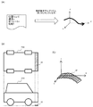
ステップS12において、図3(A)に示すように、軌跡算出部110が、挙動情報106に基づい
て3次元空間内での車両200の移動軌跡を算出する。本実施形態においては、軌跡算出部110は、挙動情報106に含まれる位置情報(緯度・経度・高度)、速度、ヨーレート、勾配情報を元に、軌跡推定アルゴリズムとしてカルマンフィルタを用いて、車両の移動軌跡を算出する。移動軌跡は、地理座標系(ワールド座標系)によって表すことができる。カルマンフィルタを用いることで、移動軌跡のスムージングが行える。なお、軌跡算出部110は
、移動軌跡の算出に地図情報も用いてマップマッチングを行うことも好ましい。本実施形態においては、移動軌跡は、挙動情報106の取得期間全体にわたって算出される。なお、
移動軌跡は、速度とヨーレートを単に積分することによって求めてもよいし、あるいは各時点の位置情報を単に連結することによって求めてもよい。
In step S12, as shown in FIG. 3A, the
The movement trajectory may be obtained by simply integrating the velocity and the yaw rate, or may be obtained by simply connecting the position information at each time point.
移動軌跡は、より詳細には図3(B)、3(C)に示すような、車両200の現在位置に対応する
線分31の軌跡である面32として求めることができる。線分31は、車両200の幅と同じ長さ
を有し、道路表面上の高さとすることが好ましい。具体的には、軌跡推定アルゴリズムによって点の軌跡(線)が得られるので、この結果を基に当該点を中心とする車両200の幅
と同じ長さの線分の軌跡を求めればよい。なお、図3(B)では、線分31が車両200の最前方
に位置するように描いているが、これは一例であり必ずしも線分31が車両200の最前方に
対応するわけではない。また、線分31の位置は道路表面の高さとすることが好ましい。これは地図情報を用いたマップマッチングにより達成できる。また、線分31の幅は必ずしも車両200の幅と同一の値とする必要はなく、車両200の幅に所定値を足した値や所定係数を掛けた値としてもよい。
More specifically, the movement trajectory can be obtained as a
以降の処理は、動画像である車載画像を構成する処理対象フレームについて繰り返し実行される(ループL1)。処理対象フレームはどのように定められてもよく、例えば全フレームを処理対象としてもよいし、所定時間おきのフレームを処理対象としてもよい。 The subsequent processing is repeatedly executed for the processing target frame constituting the in-vehicle image that is a moving image (loop L1). The processing target frame may be determined in any way. For example, all the frames may be processed, or frames every predetermined time may be processed.
ステップS14では、物体検出部114が処理対象フレームから検出対象の物体を検出する。検出対象の物体は任意であってよく、例えば、車両、歩行者(人間)などの物体が含まれる。物体検出部114は、あらかじめ検出対象の画像を用いて学習された識別器を用いて物
体を検出することができる。学習アルゴリズムは任意であって構わないが、例えば、Deformable Part ModelやDeep Learningなどの手法を用いることができる。なお、物体の検出は、処理対象フレームの1枚の画像だけをもとに行う必要はなく、それ以前および以降の
フレームの画像を用いて物体を検出してもよい。例えば、いわゆる物体追跡手法を用いて現在のフレームにおける物体を検出してもよい。また、背景抽出技術により画像内の動くものを抽出してもよい。さらに、レーダーやLIDARから得られた距離画像を用いて物体検
出に利用してもよい。さらに、白線検出を行って高信頼度で白線を検出できた場合に白線情報を利用してもよい。
In step S14, the
図4は、処理対象フレームの車載画像40と、その中で検出された3つの物体(ここでは車両)41,42,43が示されている。物体検出部114は、検出された物体の車載画像内における
位置(領域)も特定する。本実施形態では、検出物体を含む矩形が、車載画像内における検出物体の位置として特定される。
FIG. 4 shows an in-
ステップS16において、走行経路投影部112は、挙動情報及び車両情報を用いて、ステップS12において算出された車両の移動軌跡を、車載画像に投影する。上述したように車両
の移動軌跡は、ワールド座標系において求められている。また、車両の挙動情報106には
車両の位置情報が含まれ、車両設定情報108には車載カメラ202の設置位置および撮影方向が含まれる。
In step S16, the travel
ここで、図5(A),5(B)を参照して、車載カメラ202に関する車両設定情報108を説明する
。図5(A)は車両を上方から見た模式図、図5(B)は車両を側方から見た模式図である。車載
カメラ202の設置位置は、車両中心線51からのオフセット52および地上高53としてあらわ
される。設置位置に車両の前後方向が含まれてもよいが、含まれなくてもよい。また、車載カメラ202の撮影方向は、方位角54および俯角55によって表される。車両設定情報108には、車両200の幅56も含まれる。
Here, the
図6(A)に示すように、走行経路投影部112は、車両200の位置と車載カメラ202の設置
位置および撮影方向を用いて車両の移動軌跡61を座標変換することにより、投影面62における移動軌跡の領域63を求めることができる。移動軌跡61が車載画像62に投影される領域63は、移動軌跡61が実空間に存在したと仮定した場合に移動軌跡61が撮影される領域といえる。
As shown in FIG. 6 (A), the travel
図6(B)は、車載画像64に投影された移動軌跡65を示す。ここでは車両200は2車線道路の右側車線を走行しており、車載画像64に投影される移動軌跡65はその旨を反映している。なお、車載画像64には、検出物体66,67も示されている。また、図6(B)に示す画像は説明
を目的とするものであり、この画像が表示されたり、この画像のデータが生成されたりする必要はない。
FIG. 6B shows a
次のステップS17-S22の処理は、処理対象フレームの画像における検出物体ごとに実行
される(ループL2)。例えば、図6(B)に示す例では、車両66および車両67に対してそれぞれ処理が行われる。
The processing in the next steps S17 to S22 is executed for each detected object in the image of the processing target frame (loop L2). For example, in the example shown in FIG. 6 (B), processing is performed on the
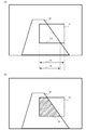
ステップS17では、経路上物体判定部116が、検出物体と、車載画像に投影された移動軌跡の重複量を求める。この重複量が大きいほど、検出物体が車両の走行経路上に位置する可能性が高い。すなわち、この重複量は、検出物体が走行経路上に位置するか否かを判定するための指標として有用である。重複量の2つの算出方法について、図7(A),7(B)を参照して説明する。
In step S17, the on-route
図7(A)は重複量の第1の算出方法を説明する図である。図7(A)には車載画像における、
検出物体の矩形領域71および投影された移動軌跡72が示されている。ここで、検出物体と移動軌跡の重複量は、矩形領域71の下辺71a全体の長さ73に対する、下辺のうち移動軌跡72に重なる部分の長さ74の比(割合)として定義することができる。
FIG. 7A is a diagram for explaining a first method for calculating the overlap amount. Fig. 7 (A) shows the in-vehicle image.
A
図7(B)は重複量の第2の算出方法を説明する図である。検出物体と移動軌跡の重複量は
、矩形領域71の全体面積に対する、矩形領域71のうち移動軌跡72と重複する領域75(斜線部)の面積の比(割合)として定義することもできる。
FIG. 7B is a diagram for explaining a second method for calculating the overlap amount. The overlap amount of the detected object and the movement locus can be defined as the ratio (ratio) of the area of the area 75 (shaded portion) overlapping the
上記第1の手法と第2の手法はいずれも利用可能であるが、検出物体の領域を矩形領域として検出し、かつ、当該矩形領域の下辺が検出物体の道路表面に対応する位置とする場合は、第1の手法が好ましい。この場合、矩形領域の下辺が移動軌跡と重複することは、検
出物体が移動軌跡上に位置することを意味するためである。
Both the first method and the second method can be used, but the detected object area is detected as a rectangular area, and the lower side of the rectangular area is set to a position corresponding to the road surface of the detected object. The first method is preferable. In this case, the fact that the lower side of the rectangular area overlaps with the movement locus means that the detected object is located on the movement locus.
あるいは、上記第1および第2の手法による2つの重複量に基づいて求められる値を、判
定に用いる重複量としてもよい。例えば、2つの値の単純平均あるいは重みづけ平均、ま
たは最大値あるいは最小値を、判定に用いる重複量としてもよい。
Alternatively, a value obtained based on the two overlap amounts according to the first and second methods may be used as the overlap amount used for the determination. For example, a simple average or weighted average of two values, or a maximum value or minimum value may be used as the overlap amount used for the determination.
ステップS18では、経路上物体判定部116は、上記のようにして求めた重複割合が所定割合以上であるか否かを判定する。この判定における閾値(所定割合)は、用途に応じて適宜決定すればよい。なお、第1の手法を用いる場合と第2の手法を用いる場合で異なる閾値が用いられてもよい。
In step S18, the on-route
重複量が所定割合以上である場合(S18-YES)、経路上物体判定部116は、検出物体が車両200の走行経路上に位置すると判定する(S20)。一方、重複量が所定割合未満である場合(S18-NO)、経路上物体判定部116は、検出物体が車両200の走行経路上に位置しないと判定する(S22)。図6(B)の例では、車両66は車両200の走行経路上に位置すると判定されるのに対し、車両67は車両200の走行経路上に位置しないと判定される。
When the overlap amount is equal to or greater than the predetermined ratio (S18-YES), the on-route
物体検出装置100は、車両200の位置、走行経路、検出物体に関する情報(例えば、物体の種類、物体の大きさ、車載画像内における位置、車両200との相対的な位置など)や検
出物体が車両200の走行経路上に位置するか否かの情報を、記憶装置に格納する。あるい
は、物体検出装置100はこれらの情報を外部の装置に出力してもよい。
The
ステップS24において、出力画像生成部118は、処理対象の車載画像に対して、車両の移動軌跡と検出物体の表示を合成した画像データを生成して、表示部に表示したり、記憶装置に格納したりする。ここで、検出物体の表示は、その物体が車両の走行経路上に位置するか否かを判別可能なように、検出物体が走行経路上に位置するか否かに応じて表示態様を異ならせることが好ましい。図8は、出力画像生成部118が生成する出力画像の例を示す図である。車載画像80に対して、車両200の移動軌跡をあらわす表示81と、2つの検出物体をあらわす表示82,83が重畳されている。ここでは、車両200の走行経路上にある物体の表示82を実線とし、走行経路上にない物体の表示83を点線としている。もちろん、線の種類を変える以外にも、線の色を変えるなどのその他の方法によって区別可能としてもよい。また、ステップS17において求めた重複量の値を表示してもよい。あるいは、走行経路上
にない物体については、表示を省略してもかまわない。
In step S24, the output
<本実施形態の有利な効果>
本実施形態によれば、車両の実際の挙動情報、特に処理対象画像の撮影後の挙動情報に基づいて車両の移動軌跡を求めているため、精度よく車両の移動軌跡を求めることができる。したがって、車載画像の中から車両の走行経路上に位置する物体を精度良く検出することができる。
<Advantageous effects of this embodiment>
According to this embodiment, since the vehicle movement trajectory is obtained based on the actual behavior information of the vehicle, in particular, the behavior information after photographing the processing target image, the vehicle movement trajectory can be obtained with high accuracy. Therefore, an object located on the travel route of the vehicle can be accurately detected from the in-vehicle image.
また、本実施形態は位置情報(GNSS位置)の精度が悪い場合であっても、移動軌跡ひいては走行経路上の物体を精度の良く検出可能である。位置情報に誤差がある場合、移動軌跡の地理座標系における位置は誤差を有するが、移動軌跡を投影する際に用いる車両の位置情報も同様の誤差が含まれる。したがって、車両に対する相対的な移動軌跡は精度よく求められる。すなわち、車両に対する相対的な移動軌跡の位置は精度よく求めることができる。このように、位置情報の精度が悪い場合であっても最終的な検出精度は低下しない。 Further, in the present embodiment, even when the accuracy of the position information (GNSS position) is poor, it is possible to detect the movement locus and thus the object on the travel route with high accuracy. When there is an error in the position information, the position of the movement locus in the geographic coordinate system has an error, but the vehicle position information used when projecting the movement locus also includes the same error. Therefore, the relative movement trajectory with respect to the vehicle is obtained with high accuracy. That is, the position of the movement trajectory relative to the vehicle can be obtained with high accuracy. Thus, even if the accuracy of the position information is poor, the final detection accuracy does not decrease.
本実施形態の処理は、画像撮影直後には実行できないため、衝突予測のようなリアルタイムの処理が要求される場合には必ずしも最適ではない。しかしながら、実測データを用いて自動運転の制御を学習する際に、単に周囲の物体の種類や位置だけでなく、これらの物体が自車両の走行経路上に位置するか否かという情報が有用である。本実施形態によれば、実測データにおいて周囲の物体が自車両の走行経路上に位置するか否かを、自動的にかつ精度よく検出することができる。したがって、自動運転用の学習データの生成に特に有用であるといえる。 Since the processing of this embodiment cannot be performed immediately after image capturing, it is not necessarily optimal when real-time processing such as collision prediction is required. However, when learning control of automatic driving using actually measured data, not only the types and positions of surrounding objects but also information on whether these objects are located on the traveling route of the host vehicle is useful. is there. According to the present embodiment, it is possible to automatically and accurately detect whether or not a surrounding object is located on the travel route of the host vehicle in the measured data. Therefore, it can be said that it is particularly useful for generating learning data for automatic driving.
<変形例>
上記の説明は、本発明の一実施形態であり本発明をその内容に限定するものではない。本発明は、その技術的思想の範囲内で種々の変形が可能である。
<Modification>
The above description is one embodiment of the present invention, and the present invention is not limited to the content. The present invention can be variously modified within the scope of its technical idea.
本発明に係る物体検出装置は、マイクロプロセッサとプログラムによって実現する代わ
りに、FPGA(Field Programmable Gate Array)などのプログラム可能な集積回路や、ASIC(Application Specific Integrated Circuit)などの専用の集積回路によって実現されてもよい。また、これらの組み合わせにより実現されてもよい。また、物体検出装置は必ずしも1台のコンピュータによって実現される必要はなく、ネットワークを介して接続され
た複数のコンピュータによって実現されてもよい。また、物体検出装置は、処理対象の車載画像を撮影する車両に搭載されてもよい。
The object detection apparatus according to the present invention is realized by a programmable integrated circuit such as an FPGA (Field Programmable Gate Array) or a dedicated integrated circuit such as an ASIC (Application Specific Integrated Circuit) instead of being realized by a microprocessor and a program. May be. Moreover, you may implement | achieve by the combination of these. In addition, the object detection device is not necessarily realized by a single computer, and may be realized by a plurality of computers connected via a network. Further, the object detection device may be mounted on a vehicle that captures a vehicle-mounted image to be processed.
本発明に係る物体検出装置が検出対象とする物体は特に限定されないことは明らかであろう。上記の説明では、車両や歩行者を例にしているが、検出対象物体はこれらに限られず任意の物体であって構わない。 It will be apparent that the object to be detected by the object detection apparatus according to the present invention is not particularly limited. In the above description, a vehicle or a pedestrian is taken as an example, but the detection target object is not limited to these and may be an arbitrary object.
図2のフローチャートに示す処理は一例にすぎず、処理の順序や内容は適宜変更可能で
ある。例えば、物体検出(S14)と移動軌跡の投影(S16)の実行順序は逆にしてもよいし、並行して行ってもよい。
The processing shown in the flowchart of FIG. 2 is merely an example, and the order and contents of the processing can be changed as appropriate. For example, the execution order of the object detection (S14) and the movement trajectory projection (S16) may be reversed or may be performed in parallel.
また、ステップS12においてあらかじめ挙動情報から車両200の移動軌跡全体を求めているが、処理対象フレームの車載画像ごとに、当該画像の撮影時刻以降の所定期間の挙動データを用いて移動軌跡を求めてもよい。この場合は、車両の移動軌跡をワールド座標系(地理座標系)で求めずに、ローカル座標系(車両座標系)で求めてもよい。また、移動軌跡を求める期間(上記の所定期間)は適宜定めることができる。例えば、移動軌跡を求める期間は、予め定められた期間であってもよいし、移動軌跡が所定の距離(以上)となる期間であってもよい。また、当該期間は、走行中の道路形状に応じて決定してもよく、曲線道路では直線道路と比較してより短い期間の移動軌跡を求めるようにしてもよい。
In step S12, the entire movement trajectory of the
また、車両の移動軌跡を求める際に、各時点での車両に対応する線分の軌跡(面)を車両の移動軌跡として求めているが、各時点での車両に対応する点の軌跡(線)を先に求め、その後この軌跡を車両の幅に応じて拡張して同様の面状の軌跡を求めることもできる。 In addition, when obtaining the movement trajectory of the vehicle, the trajectory (plane) of the line segment corresponding to the vehicle at each time point is obtained as the movement trajectory of the vehicle. ) First, and then the trajectory can be expanded according to the width of the vehicle to obtain a similar planar trajectory.
また、ステップS24における表示用画像データの生成処理は省略してもかまわない。 In addition, the display image data generation process in step S24 may be omitted.
また、上記の実施形態では、車載画像における、検出物体と投影された移動軌跡の重複量に応じて、検出物体が車両200の走行経路上に位置するか否かを判定している。しかし
ながら、この判定を行わずに、上記の重複量または重複量に基づいて算出される値(スコア)を、検出物体が車両200の走行経路上に位置する確信度として出力してもよい。例え
ば、自動運転時に検出される前方車両が自車両の走行経路上に位置するか否かは確率的にしか判断できない。したがって、その確率(確信度)に応じて制御を異ならせるような学習を行うためには、確信度を出力する構成が好適といえる。
In the above embodiment, whether or not the detected object is located on the travel route of the
100 物体検出装置
110 軌跡算出部 112 走行経路投影部 114 物体検出部
116 経路上物体判定部 118 出力画像生成部
200 車両
100 Object detection device
110
116 On-path
200 vehicles
Claims (10)
前記車両の車載カメラが撮影した車載画像を取得する車載画像取得ステップと、
前記車載画像の撮影以降の前記車両の挙動情報を取得する挙動情報取得ステップと、
前記挙動情報に基づいて、前記車両の移動軌跡を求める軌跡算出ステップと、
前記移動軌跡に基づいて、前記車載画像において前記移動軌跡に対応する領域を求める領域算出ステップと、
前記車載画像から検出対象の物体を検出する物体検出ステップと、
前記物体検出ステップにおいて検出された物体について、前記車載画像における前記移動軌跡に対応する領域との重複量を算出する算出ステップと、
を含む、物体検出方法。 An object detection method for detecting an object located on a travel route of a vehicle from an image taken by a vehicle equipped with an in-vehicle camera,
An in-vehicle image acquisition step of acquiring an in-vehicle image captured by the in-vehicle camera of the vehicle;
Behavior information acquisition step for acquiring behavior information of the vehicle after taking the in-vehicle image;
A trajectory calculating step for obtaining a movement trajectory of the vehicle based on the behavior information;
An area calculation step for obtaining an area corresponding to the movement locus in the in-vehicle image based on the movement locus;
An object detection step of detecting an object to be detected from the in-vehicle image;
A calculation step of calculating an overlap amount of the object detected in the object detection step with an area corresponding to the movement locus in the vehicle-mounted image;
An object detection method including:
請求項1に記載の物体検出方法。 A determination step of determining, among the objects detected in the object detection step, an object having the overlapping amount equal to or greater than a predetermined ratio as an object located on a travel route of the vehicle;
The object detection method according to claim 1.
請求項1または2に記載の物体検出方法。 In the locus calculation step, a locus of a line segment corresponding to the width of the vehicle is obtained as a movement locus of the vehicle.
The object detection method according to claim 1 or 2.
前記判定ステップでは、前記物体が存在する領域のうち、前記移動軌跡に対応する領域に含まれる部分の割合を、前記重複量として算出する、
請求項1から3のいずれか1項に記載の物体検出方法。 In the object detection step, a region where the object exists in the vehicle-mounted image is obtained,
In the determination step, a ratio of a portion included in an area corresponding to the movement locus in an area where the object exists is calculated as the overlap amount.
The object detection method of any one of Claim 1 to 3.
前記算出ステップでは、前記物体が存在する矩形領域の下辺のうち、前記移動軌跡に対応する領域に含まれる部分の割合を、前記重複量として算出する、
請求項1から3のいずれか1項に記載の物体検出方法。 In the object detection step, a rectangular area where the object exists is obtained,
In the calculation step, a ratio of a portion included in an area corresponding to the movement locus in a lower side of the rectangular area where the object exists is calculated as the overlap amount.
The object detection method of any one of Claim 1 to 3.
請求項1から5のいずれか1項に記載の物体検出方法。 An image generation step of outputting image data in which the region corresponding to the movement locus obtained in the region calculation step and the display for specifying the object detected in the object detection step are superimposed on the in-vehicle image; Including,
The object detection method according to claim 1.
請求項6に記載の物体検出方法。 In the image generation step, the display is generated in a mode corresponding to the overlap amount.
The object detection method according to claim 6.
前記車載画像の撮影以降の前記車両の挙動情報を取得する挙動情報取得手段と、
前記挙動情報に基づいて、前記車両の移動軌跡を求める軌跡算出手段と、
前記移動軌跡に基づいて、前記車載画像において前記移動軌跡に対応する領域を求める領域算出手段と、
前記車載画像から検出対象の物体を検出する物体検出手段と、
検出された物体について、前記車載画像における前記移動軌跡に対応する領域との重複量を算出する判定手段と、
を含む、物体検出装置。 In-vehicle image acquisition means for acquiring an in-vehicle image captured by the in-vehicle camera of the vehicle;
Behavior information acquisition means for acquiring behavior information of the vehicle after photographing the vehicle-mounted image;
Based on the behavior information, a trajectory calculating means for obtaining a moving trajectory of the vehicle;
An area calculating means for obtaining an area corresponding to the movement locus in the in-vehicle image based on the movement locus;
Object detection means for detecting an object to be detected from the in-vehicle image;
A determination unit that calculates an overlap amount with a region corresponding to the movement locus in the in-vehicle image for the detected object;
An object detection device.
請求項8に記載の物体検出装置。 The determination means determines that an object whose overlapping amount is a predetermined ratio or more among detected objects is an object located on a travel route of the vehicle.
The object detection apparatus according to claim 8.
Priority Applications (1)
| Application Number | Priority Date | Filing Date | Title |
|---|---|---|---|
| JP2016017197A JP6520740B2 (en) | 2016-02-01 | 2016-02-01 | Object detection method, object detection device, and program |
Applications Claiming Priority (1)
| Application Number | Priority Date | Filing Date | Title |
|---|---|---|---|
| JP2016017197A JP6520740B2 (en) | 2016-02-01 | 2016-02-01 | Object detection method, object detection device, and program |
Publications (3)
| Publication Number | Publication Date |
|---|---|
| JP2017138660A true JP2017138660A (en) | 2017-08-10 |
| JP2017138660A5 JP2017138660A5 (en) | 2018-06-21 |
| JP6520740B2 JP6520740B2 (en) | 2019-05-29 |
Family
ID=59564990
Family Applications (1)
| Application Number | Title | Priority Date | Filing Date |
|---|---|---|---|
| JP2016017197A Active JP6520740B2 (en) | 2016-02-01 | 2016-02-01 | Object detection method, object detection device, and program |
Country Status (1)
| Country | Link |
|---|---|
| JP (1) | JP6520740B2 (en) |
Cited By (10)
| Publication number | Priority date | Publication date | Assignee | Title |
|---|---|---|---|---|
| WO2019116423A1 (en) * | 2017-12-11 | 2019-06-20 | 本田技研工業株式会社 | Teacher data collection device |
| JP2019124986A (en) * | 2018-01-12 | 2019-07-25 | 株式会社日立国際電気 | Failure detection system |
| CN110197097A (en) * | 2018-02-24 | 2019-09-03 | 北京图森未来科技有限公司 | A kind of port area monitoring method and system, central control system |
| WO2019194255A1 (en) * | 2018-04-05 | 2019-10-10 | 株式会社小糸製作所 | Arithmetic processing device, object identification system, object identification method, automobile, and vehicular lighting fixture |
| CN111243281A (en) * | 2018-11-09 | 2020-06-05 | 杭州海康威视系统技术有限公司 | Road multi-video joint detection system and detection method |
| US10698396B2 (en) | 2017-11-17 | 2020-06-30 | Kabushiki Kaisha Toshiba | Information processing apparatus, information processing method, and recording medium |
| CN112166434A (en) * | 2018-05-25 | 2021-01-01 | 罗伯特·博世有限公司 | Operation assistance method, control unit, operation assistance system, and work device |
| CN113178097A (en) * | 2020-01-09 | 2021-07-27 | 大陆汽车有限责任公司 | Method for establishing probability map of unoccupied space comprising static target and dynamic target |
| JP2023039286A (en) * | 2021-09-08 | 2023-03-20 | ソフトバンク株式会社 | Determination apparatus, program, and determination method |
| CN110197097B (en) * | 2018-02-24 | 2024-04-19 | 北京图森智途科技有限公司 | Harbor district monitoring method and system and central control system |
Citations (5)
| Publication number | Priority date | Publication date | Assignee | Title |
|---|---|---|---|---|
| JP2000177513A (en) * | 1998-12-16 | 2000-06-27 | Toyota Autom Loom Works Ltd | Backing vehicle up assisting device and vehicle |
| JP2005202787A (en) * | 2004-01-16 | 2005-07-28 | Denso Corp | Display device for vehicle |
| JP2005236540A (en) * | 2004-02-18 | 2005-09-02 | Matsushita Electric Ind Co Ltd | On-vehicle camera device |
| WO2011089812A1 (en) * | 2010-01-19 | 2011-07-28 | アイシン精機株式会社 | Vehicle periphery monitoring device |
| JP2015209129A (en) * | 2014-04-25 | 2015-11-24 | 富士重工業株式会社 | Vehicular steering control apparatus |
-
2016
- 2016-02-01 JP JP2016017197A patent/JP6520740B2/en active Active
Patent Citations (5)
| Publication number | Priority date | Publication date | Assignee | Title |
|---|---|---|---|---|
| JP2000177513A (en) * | 1998-12-16 | 2000-06-27 | Toyota Autom Loom Works Ltd | Backing vehicle up assisting device and vehicle |
| JP2005202787A (en) * | 2004-01-16 | 2005-07-28 | Denso Corp | Display device for vehicle |
| JP2005236540A (en) * | 2004-02-18 | 2005-09-02 | Matsushita Electric Ind Co Ltd | On-vehicle camera device |
| WO2011089812A1 (en) * | 2010-01-19 | 2011-07-28 | アイシン精機株式会社 | Vehicle periphery monitoring device |
| JP2015209129A (en) * | 2014-04-25 | 2015-11-24 | 富士重工業株式会社 | Vehicular steering control apparatus |
Cited By (24)
| Publication number | Priority date | Publication date | Assignee | Title |
|---|---|---|---|---|
| US10698396B2 (en) | 2017-11-17 | 2020-06-30 | Kabushiki Kaisha Toshiba | Information processing apparatus, information processing method, and recording medium |
| JP6993428B2 (en) | 2017-12-11 | 2022-01-13 | 本田技研工業株式会社 | Teacher data generator |
| WO2019116423A1 (en) * | 2017-12-11 | 2019-06-20 | 本田技研工業株式会社 | Teacher data collection device |
| JPWO2019116423A1 (en) * | 2017-12-11 | 2020-11-26 | 本田技研工業株式会社 | Teacher data generator |
| US11308357B2 (en) | 2017-12-11 | 2022-04-19 | Honda Motor Co., Ltd. | Training data generation apparatus |
| JP2019124986A (en) * | 2018-01-12 | 2019-07-25 | 株式会社日立国際電気 | Failure detection system |
| JP7125843B2 (en) | 2018-01-12 | 2022-08-25 | 株式会社日立国際電気 | Fault detection system |
| CN110197097A (en) * | 2018-02-24 | 2019-09-03 | 北京图森未来科技有限公司 | A kind of port area monitoring method and system, central control system |
| CN110197097B (en) * | 2018-02-24 | 2024-04-19 | 北京图森智途科技有限公司 | Harbor district monitoring method and system and central control system |
| CN111989709A (en) * | 2018-04-05 | 2020-11-24 | 株式会社小糸制作所 | Arithmetic processing device, object recognition system, object recognition method, automobile, and vehicle lamp |
| JPWO2019194255A1 (en) * | 2018-04-05 | 2021-04-22 | 株式会社小糸製作所 | Arithmetic processing unit, object identification system, object identification method, automobile, vehicle lighting equipment |
| US11341604B2 (en) | 2018-04-05 | 2022-05-24 | Koito Manufacturing Co., Ltd. | Processing device for object identification |
| WO2019194255A1 (en) * | 2018-04-05 | 2019-10-10 | 株式会社小糸製作所 | Arithmetic processing device, object identification system, object identification method, automobile, and vehicular lighting fixture |
| JP7217741B2 (en) | 2018-04-05 | 2023-02-03 | 株式会社小糸製作所 | Arithmetic processor, object identification system, object identification method, automobile, vehicle lamp |
| JP7244546B2 (en) | 2018-05-25 | 2023-03-22 | ロベルト・ボッシュ・ゲゼルシャフト・ミト・ベシュレンクテル・ハフツング | Driving support method, control unit, driving support system, and operating device |
| JP2021525423A (en) * | 2018-05-25 | 2021-09-24 | ロベルト・ボッシュ・ゲゼルシャフト・ミト・ベシュレンクテル・ハフツングRobert Bosch Gmbh | Driving assistance methods, control units, driving assistance systems, and operating devices |
| CN112166434A (en) * | 2018-05-25 | 2021-01-01 | 罗伯特·博世有限公司 | Operation assistance method, control unit, operation assistance system, and work device |
| US11403854B2 (en) | 2018-05-25 | 2022-08-02 | Robert Bosch Gmbh | Operating assistance method, control unit, operating assistance system and working device |
| CN111243281A (en) * | 2018-11-09 | 2020-06-05 | 杭州海康威视系统技术有限公司 | Road multi-video joint detection system and detection method |
| CN113178097B (en) * | 2020-01-09 | 2023-03-14 | 大陆智行德国有限公司 | Method for establishing probability map of unoccupied space comprising static target and dynamic target |
| US11820404B2 (en) | 2020-01-09 | 2023-11-21 | Continental Automotive Gmbh | Method for creating a probabilistic free space map with static and dynamic objects |
| CN113178097A (en) * | 2020-01-09 | 2021-07-27 | 大陆汽车有限责任公司 | Method for establishing probability map of unoccupied space comprising static target and dynamic target |
| JP2023039286A (en) * | 2021-09-08 | 2023-03-20 | ソフトバンク株式会社 | Determination apparatus, program, and determination method |
| JP7303852B2 (en) | 2021-09-08 | 2023-07-05 | ソフトバンク株式会社 | Determination device, program, and determination method |
Also Published As
| Publication number | Publication date |
|---|---|
| JP6520740B2 (en) | 2019-05-29 |
Similar Documents
| Publication | Publication Date | Title |
|---|---|---|
| JP6520740B2 (en) | Object detection method, object detection device, and program | |
| CN109215433B (en) | Vision-based driving scenario generator for automated driving simulation | |
| Kim et al. | Sensor fusion algorithm design in detecting vehicles using laser scanner and stereo vision | |
| JP7052786B2 (en) | Display control device and display control program | |
| JPWO2018221453A1 (en) | Output device, control method, program, and storage medium | |
| US20190347808A1 (en) | Monocular Visual Odometry: Speed And Yaw Rate Of Vehicle From Rear-View Camera | |
| KR102086270B1 (en) | Control method and traveling control device of the traveling control device | |
| JP2010072807A (en) | Device for detecting and determining road boundary | |
| JP2018092483A (en) | Object recognition device | |
| JP6806891B2 (en) | Information processing equipment, control methods, programs and storage media | |
| CN110470309A (en) | This truck position apparatus for predicting | |
| JP6936098B2 (en) | Object estimation device | |
| JP2007240422A (en) | Depression angle calculator, depression angle calculation method, depression angle calculation program, and image processor | |
| JP2018048949A (en) | Object recognition device | |
| JP6941178B2 (en) | Automatic operation control device and method | |
| JP6943127B2 (en) | Position correction method, vehicle control method and position correction device | |
| US20220205804A1 (en) | Vehicle localisation | |
| JP2018189463A (en) | Vehicle position estimating device and program | |
| JP2020118575A (en) | Inter-vehicle distance measurement device, error model generation device, learning model generation device, and method and program thereof | |
| JP2024020641A (en) | location estimation system | |
| CN113795726B (en) | Self-position correction method and self-position correction device | |
| JP2019148889A (en) | Road boundary detection device | |
| KR102003387B1 (en) | Method for detecting and locating traffic participants using bird's-eye view image, computer-readerble recording medium storing traffic participants detecting and locating program | |
| JP2023152109A (en) | Feature detection device, feature detection method and computer program for detecting feature | |
| JP2019196941A (en) | Own vehicle position estimating device |
Legal Events
| Date | Code | Title | Description |
|---|---|---|---|
| A521 | Request for written amendment filed |
Free format text: JAPANESE INTERMEDIATE CODE: A523 Effective date: 20180501 |
|
| A621 | Written request for application examination |
Free format text: JAPANESE INTERMEDIATE CODE: A621 Effective date: 20180501 |
|
| TRDD | Decision of grant or rejection written | ||
| A01 | Written decision to grant a patent or to grant a registration (utility model) |
Free format text: JAPANESE INTERMEDIATE CODE: A01 Effective date: 20190402 |
|
| A977 | Report on retrieval |
Free format text: JAPANESE INTERMEDIATE CODE: A971007 Effective date: 20190329 |
|
| A61 | First payment of annual fees (during grant procedure) |
Free format text: JAPANESE INTERMEDIATE CODE: A61 Effective date: 20190415 |
|
| R151 | Written notification of patent or utility model registration |
Ref document number: 6520740 Country of ref document: JP Free format text: JAPANESE INTERMEDIATE CODE: R151 |