WO2014109202A1 - プレス部品の成形方法、プレス部品の製造方法およびプレス部品の成形用金型 - Google Patents
プレス部品の成形方法、プレス部品の製造方法およびプレス部品の成形用金型 Download PDFInfo
- Publication number
- WO2014109202A1 WO2014109202A1 PCT/JP2013/084109 JP2013084109W WO2014109202A1 WO 2014109202 A1 WO2014109202 A1 WO 2014109202A1 JP 2013084109 W JP2013084109 W JP 2013084109W WO 2014109202 A1 WO2014109202 A1 WO 2014109202A1
- Authority
- WO
- WIPO (PCT)
- Prior art keywords
- forming
- boss
- shape
- die
- punch
- Prior art date
- Legal status (The legal status is an assumption and is not a legal conclusion. Google has not performed a legal analysis and makes no representation as to the accuracy of the status listed.)
- Ceased
Links
Images

Classifications
-
- B—PERFORMING OPERATIONS; TRANSPORTING
- B21—MECHANICAL METAL-WORKING WITHOUT ESSENTIALLY REMOVING MATERIAL; PUNCHING METAL
- B21D—WORKING OR PROCESSING OF SHEET METAL OR METAL TUBES, RODS OR PROFILES WITHOUT ESSENTIALLY REMOVING MATERIAL; PUNCHING METAL
- B21D28/00—Shaping by press-cutting; Perforating
- B21D28/24—Perforating, i.e. punching holes
- B21D28/243—Perforating, i.e. punching holes in profiles
-
- B—PERFORMING OPERATIONS; TRANSPORTING
- B21—MECHANICAL METAL-WORKING WITHOUT ESSENTIALLY REMOVING MATERIAL; PUNCHING METAL
- B21D—WORKING OR PROCESSING OF SHEET METAL OR METAL TUBES, RODS OR PROFILES WITHOUT ESSENTIALLY REMOVING MATERIAL; PUNCHING METAL
- B21D19/00—Flanging or other edge treatment, e.g. of tubes
- B21D19/08—Flanging or other edge treatment, e.g. of tubes by single or successive action of pressing tools, e.g. vice jaws
-
- B—PERFORMING OPERATIONS; TRANSPORTING
- B21—MECHANICAL METAL-WORKING WITHOUT ESSENTIALLY REMOVING MATERIAL; PUNCHING METAL
- B21D—WORKING OR PROCESSING OF SHEET METAL OR METAL TUBES, RODS OR PROFILES WITHOUT ESSENTIALLY REMOVING MATERIAL; PUNCHING METAL
- B21D19/00—Flanging or other edge treatment, e.g. of tubes
- B21D19/08—Flanging or other edge treatment, e.g. of tubes by single or successive action of pressing tools, e.g. vice jaws
- B21D19/088—Flanging or other edge treatment, e.g. of tubes by single or successive action of pressing tools, e.g. vice jaws for flanging holes
-
- B—PERFORMING OPERATIONS; TRANSPORTING
- B21—MECHANICAL METAL-WORKING WITHOUT ESSENTIALLY REMOVING MATERIAL; PUNCHING METAL
- B21D—WORKING OR PROCESSING OF SHEET METAL OR METAL TUBES, RODS OR PROFILES WITHOUT ESSENTIALLY REMOVING MATERIAL; PUNCHING METAL
- B21D28/00—Shaping by press-cutting; Perforating
- B21D28/02—Punching blanks or articles with or without obtaining scrap; Notching
- B21D28/14—Dies
-
- B—PERFORMING OPERATIONS; TRANSPORTING
- B21—MECHANICAL METAL-WORKING WITHOUT ESSENTIALLY REMOVING MATERIAL; PUNCHING METAL
- B21D—WORKING OR PROCESSING OF SHEET METAL OR METAL TUBES, RODS OR PROFILES WITHOUT ESSENTIALLY REMOVING MATERIAL; PUNCHING METAL
- B21D28/00—Shaping by press-cutting; Perforating
- B21D28/24—Perforating, i.e. punching holes
- B21D28/26—Perforating, i.e. punching holes in sheets or flat parts
-
- B—PERFORMING OPERATIONS; TRANSPORTING
- B21—MECHANICAL METAL-WORKING WITHOUT ESSENTIALLY REMOVING MATERIAL; PUNCHING METAL
- B21D—WORKING OR PROCESSING OF SHEET METAL OR METAL TUBES, RODS OR PROFILES WITHOUT ESSENTIALLY REMOVING MATERIAL; PUNCHING METAL
- B21D28/00—Shaping by press-cutting; Perforating
- B21D28/24—Perforating, i.e. punching holes
- B21D28/34—Perforating tools; Die holders
-
- B—PERFORMING OPERATIONS; TRANSPORTING
- B21—MECHANICAL METAL-WORKING WITHOUT ESSENTIALLY REMOVING MATERIAL; PUNCHING METAL
- B21J—FORGING; HAMMERING; PRESSING METAL; RIVETING; FORGE FURNACES
- B21J5/00—Methods for forging, hammering, or pressing; Special equipment or accessories therefor
- B21J5/06—Methods for forging, hammering, or pressing; Special equipment or accessories therefor for performing particular operations
- B21J5/10—Piercing billets
Definitions
- the present invention relates to a method for forming a metal pressed part formed by raising a cylindrical boss on a plate-like base, a method for manufacturing the pressed part, and a mold for forming the pressed part.
- a metal press part formed by raising a cylindrical boss part on a plate-like base part is used.
- these press parts are formed by drawing, burring, punching and cutting.
- Patent Document 1 after forming a preformed portion in which the central portion of the cylindrical body is closed while protruding on a flat blank, the closed portion in the preformed portion is cut out by piercing.
- a method for forming a pressed part for forming a cylindrical boss portion penetrating through the above method is disclosed.
- the conventional method for forming a press part has a problem that there are many restrictions on the shape of the boss part formed on the press part. That is, in the conventional method for forming a pressed part, since all of the closed portion in the pre-formed part becomes scrap by piercing of the pilot hole and the material usage efficiency is low, it is difficult to secure the protruding amount and thickness at the boss part. In addition, in piercing processing for forming a through hole in a material, generally, a through hole having a hole diameter equal to or less than the plate thickness of the material cannot be punched. Therefore, in the conventional press part molding method, the inner diameter of the boss portion is large. However, there was a problem that it was limited to the thickness of the blank.
- the present invention has been made to address the above-described problems, and its purpose is to reduce the size of the equipment used for a metal press part formed by raising a cylindrical boss portion on a plate-like base portion, and
- An object of the present invention is to provide a press part molding method, a press part manufacturing method, and a press part molding die that can be simplified and can form a wide range of boss portions.
- a feature of the present invention is a method of forming a metal pressed part formed by raising a cylindrical boss part on a plate-like base part, and the outer shape of the boss part in the pressed part
- a cylindrical outer shape forming part formed in a shape corresponding to the pierce dies each having a die side cutting edge formed to protrude inward by the thickness of the boss part with respect to the outer shape forming part, and a rod-like body
- a pierce punch having a punch-side cutting edge that is paired with a die-side cutting edge in a state in which a bullet-shaped inner forming shape portion is formed at the tip portion and overhanging the inner forming shape portion is prepared.
- Preliminary boss part molding that forms a preliminary boss part in which a part of the blank is protruded by pressing a plate-like blank using a bullet-type punch having a bullet-shaped tip part Process and spare button
- the preliminary hole forming step of forming a through hole formed at the tip of the part, and a piercing die disposed opposite to the outer side of the preliminary boss part and a piercing punch disposed opposite to the inner side of the preliminary boss part are preliminarily displaced. After allowing the inner formed shape to enter the boss part to cause a part of the preliminary boss part to flow toward the outer shape forming part side, the other part of the preliminary boss part is separated from the die side cutting edge and the punch side cutting edge. And a boss part forming step of cutting by the above.
- a method for forming a press part is the method of forming a preliminary boss part that protrudes in a convex shape with respect to a blank as a material of the press part, and then the tip of the preliminary boss part.
- a pilot hole is formed in Then, in the method of forming a pressed part, a part of the preliminary boss part is caused to flow toward the outer shape forming part side of the piercing die by allowing the inner forming part of the piercing punch to enter the preliminary boss part in which the pilot hole is formed. Thereafter, another part of the preliminary boss portion is cut with a die side cutting edge and a punch side cutting edge.
- a convex preliminary boss portion is formed and a prepared hole is formed at the tip of the preliminary boss portion.
- the tip end side of the preliminary boss part can be formed thin, it is possible to easily form a pilot hole with an inner diameter smaller than the blank plate thickness and minimize the volume of the part to be cut by the piercing punch and the piercing die. Can be limited.
- the equipment configuration used for forming the pressed part can be reduced in size and simplified, and a wide range of shapes, specifically, an amount of protrusion and a wall thickness compared to the prior art It is possible to mold a boss portion with increased s.
- the preliminary boss portion forming step forms a part of the preliminary boss portion to a thickness of 1/10 or less of the plate material.
- the method for forming a pressed part is that the tip of the preliminary boss part is formed to a thickness of 1/10 or less of the plate material in the preliminary boss part forming step.
- a pilot hole having an inner diameter smaller than the plate thickness of the plate material can be easily formed.
- the present invention can be implemented not only as an invention of a method for molding a pressed part, but also as an invention of a method for manufacturing a pressed part and a mold for molding the pressed part.
- a method for manufacturing a pressed part is a method for manufacturing a metal pressed part in which a cylindrical boss part is formed on a plate-like base part, and has an outer shape of the boss part in the pressed part.
- Pierced dies each having a die-side cutting edge that is formed to protrude inward by the thickness of the boss part with respect to the cylindrical outer formed part formed in a corresponding shape, and the tip of the rod-shaped body
- a pierce punch having a punch-side cutting edge that is paired with a die-side cutting edge in a state where a bullet-shaped inner forming-shaped part is formed on the part and is overhanging the inner-forming shaped part is prepared.
- the pilot hole forming step for forming a through hole including a through hole at the tip portion, and the piercing die disposed opposite to the outer side of the preliminary boss portion and the piercing punch disposed opposite to the inner side of the preliminary boss portion are relatively displaced.
- the part of the preliminary boss part is caused to flow toward the outer shape forming part by allowing the inner forming part to enter, and then the other part of the preliminary boss part is cut by the die side cutting edge and the punch side cutting edge.
- a press part molding die is a metal press part molding die formed by raising a cylindrical boss part on a plate-like base part, and has an outer shape of the boss part in the press part.
- a cylindrical outer shape forming part formed in a shape corresponding to the pierce dies each having a die side cutting edge formed to protrude inward by the thickness of the boss part with respect to the outer shape forming part, and a rod-like body
- a bullet-shaped inner forming part is formed at the tip, and a piercing punch having a punch side cutting edge that is paired with the die side cutting edge in a state of overhanging the inner forming part. Good.
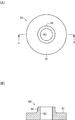
- (A), (B) has shown the outline of the external appearance structure of the press component shape
- (A) is a top view of a press component
- B) is a cross-sectional view of the pressed part as seen from line AA shown in FIG.
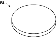
- FIG. 1 It is a perspective view which shows the outline of the external appearance structure of the blank used as the material before shape
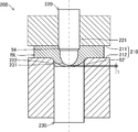
- FIG. 1 It is sectional drawing which shows the manufacturing process of the preliminary
- FIG. 1A and 1B show a schematic configuration of a press part 90 formed by the press part forming method according to the present invention
- FIG. 1A is a plan view of the press part 90.
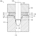
- FIG. 2 is a cross-sectional view schematically showing a state in which the press part 90 is formed by the press part forming method according to the present invention.
- Note that each drawing referred to in the present specification is schematically represented by exaggerating some of the components in order to facilitate understanding of the present invention. For this reason, the dimension, ratio, etc. between each component may differ.
- This press part 90 is a part used for assembling so-called machine parts constituting various mechanical devices, and presses steel plate materials (for example, carbon steel such as SPCC, SPCD, SPCE, S35C, and high-tensile steel). It is a molded product.
- This press part 90 is formed and formed in a state in which a cylindrical boss portion 92 projects on a plate-like base portion 91.
- a through hole 93 is formed in the press component 90 in a state of penetrating the base portion 91 and the boss portion 92.
- the through-hole 93 in this press component 90 is utilized as a mounting hole of machine parts, such as a tapped hole, a caulking hole, or a bearing.
- the molding die 100 is mainly composed of a piercing die 110, a holding body 120, and a piercing punch 130.
- the piercing die 110 cooperates with the holding body 120 to fix and support the preform 90 ′, which is a semi-finished product of the press part 90, and presses and cuts the preform 90 ′ in cooperation with the piercing punch 130.
- This is a mold for forming the pressed part 90, and is formed by forming die steel into a substantially cylindrical shape. More specifically, the piercing die 110 mainly includes a receiving portion 111, an outer shape forming portion 112, and a die side cutting edge 113.
- the receiving portion 111 is a portion that fixes and supports the base portion 91 in the preform 90 ′ together with the holding body 120, and an end face (upper side surface in the drawing) facing the holding body 120 in the cylindrical piercing die 110. It is formed in a flat ring shape. On the inner peripheral side of the receiving portion 111, an outer shape forming portion 112 is continuously formed.
- the outer shape forming portion 112 is a portion for forming the outer peripheral portion of the boss portion 92 of the pressed part 90, and has a shape corresponding to the outer peripheral shape of the boss portion 92, that is, a concave shape obtained by inverting the outer peripheral shape of the boss portion 92. It is formed into a shape.
- the bottom portion of the outer shape forming portion 112 is formed so as to project in a ring shape toward the inner side of the outer shape forming portion 112 with a width corresponding to the thickness of the boss portion 92 in order to form a ring-shaped end surface of the boss portion 92.
- a die side cutting edge 113 is formed at the inner peripheral end.
- the die-side cutting edge 113 is a ring-shaped blade portion for cutting and removing a part of a preliminary boss portion 92 ′ described later in the preform 90 ′ by cutting in cooperation with the piercing punch 130.
- a guide hole 114 formed through the piercing die 110 is connected to the die-side cutting edge 113.
- the guide hole 114 is a hole for guiding the piercing punch 130 while forming the die-side cutting edge 113 together with the outer shape forming portion 112, and has an inner diameter on which the piercing punch 130 can slide.
- the hold body 120 is a die for fixing and supporting the preform 90 'in cooperation with the piercing die 110, and is configured by forming a die steel in a substantially cylindrical shape. More specifically, the hold body 120 mainly includes a pressing portion 121 and a guide hole 122.
- the pressing part 121 is a part that fixes and supports the base part 91 in the preform 90 ′ together with the receiving part 111 of the piercing die 110, and is an end face (opposing the piercing die 110) in the cylindrical holding body 120. It is formed in a flat ring shape on the lower side in the figure.
- the guide hole 122 is a hole for guiding the piercing punch 130, and is formed to have an inner diameter on which the piercing punch 130 can slide.
- the piercing punch 130 is a rod-shaped mold for forming the pressed part 90 by pressing and cutting the preform 90 ′ in cooperation with the piercing die 110, and is formed by forming a die steel in a substantially cylindrical shape. It is configured. More specifically, the piercing punch 130 mainly includes an inner forming portion 131, a punch side cutting edge 132, and a straight portion 133.
- the inner forming portion 131 pushes the preliminary boss portion 92 ′ of the preform 90 ′ from the inside to flow toward the outer shape forming portion 112 side of the piercing die 110, thereby causing each of the base portion 91 and the boss portion 92 of the press part 90 to move.
- the inner peripheral portion that is, a portion for forming the through-hole 93, is formed in a cannonball shape whose outer diameter increases in a parabolic shape, and from the end of the portion formed in the same bullet shape toward the straight portion 133.
- the diameter is increased in a tapered shape.
- the largest outer diameter of the inner forming part 131 corresponds to the inner diameter of the through hole 93 of the press part 90.
- a punch side cutting edge 132 is formed at a boundary portion between the inner forming portion 131 and the straight portion 133.
- the punch-side cutting blade 132 is a ring-shaped blade portion for cutting and removing a part of the preliminary boss portion 92 ′ in the preform 90 ′ by cutting in cooperation with the piercing die 110.
- the straight part 133 is a part for forming the punch side cutting edge 132 while supporting the inner forming part 131 and molding the inner peripheral part of the through hole 93 in the press part 90, and is formed in a round bar shape. .
- the outer diameter of the straight portion 133 corresponds to the inner diameter of the through hole 93 in the press part 90.
- the piercing die 110, the holding body 120, and the piercing punch 130 constituting the molding die 100 are used by being attached to a not-shown press working machine for forming the press part 90 by pressing the preform 90 ′. It is done.
- the piercing die 110 is fixedly provided in the press machine.
- the holding body 120 and the piercing punch 130 are provided in the press machine so as to be coaxial with the piercing die 110 and displaceable in a direction approaching and separating from the piercing die 110.
- FIG. 3 is a flowchart showing an operation process of press forming of the press part 90.
- the operator prepares a blank BL in the first step. Specifically, as shown in FIG. 4, the worker uses a flat blank BL formed of a steel plate (for example, carbon steel such as SPCC, SPCD, SPCE, S35C, and high-tensile steel) in a circular shape. prepare.
- a steel plate for example, carbon steel such as SPCC, SPCD, SPCE, S35C, and high-tensile steel
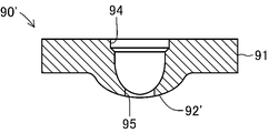
- the worker forms the preliminary boss portion 92 'on the blank BL in the second step.
- the preliminary boss portion 92 ′ is a convex portion formed in a shape in which the outer shape protrudes from the blank BL into a substantially spherical shape and the inner shape is depressed in a bullet shape.
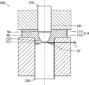
- the step of forming the preliminary boss portion 92 ' is performed using, for example, a drawing machine (not shown) provided with a preliminary molding die 200 as shown in FIG.
- the pre-molding die 200 is a die for forming a pre-boss boss 92 ′ on the blank BL by plastic working a flat blank BL, and is mainly composed of a work chuck 210, a punch 220, and an ejector 230.
- the work chuck 210 is a die composed of a pair of a movable die 211 and a fixed die 212 for fixing and supporting the peripheral portion of the blank BL, and each die steel is formed in a substantially cylindrical shape.
- each die steel is formed in a substantially cylindrical shape.
- the punch 220 is a movable mold for forming the inner shape of the preliminary boss portion 92 ′ by pressing the central portion of the blank BL, and is configured by forming die steel in a substantially cylindrical shape. More specifically, the punch 220 includes a cylindrical portion 221 that extends in a cylindrical shape, and a bullet portion 222 that is formed in a bullet shape at the end of the cylindrical portion 221 via a tapered portion. In addition, the ejector 230 receives a portion of the blank BL pressed by the punch 220 to form a part of the outer shape of the spare boss portion 92 ′, and the spare boss portion 92 ′ fitted in the hole portion of the fixed die 212 is formed in the same hole.
- It is a movable mold for extruding from a part, and is formed by forming die steel in a substantially cylindrical shape.
- the receiving portion 231 for receiving the blank BL in the ejector 230 is formed in a planar shape.
- the operator sets the blank BL in the preforming mold 200 and operates the drawing machine equipped with the preforming mold 200 to start the forming process of the preliminary boss portion 92 ′.
- the drawing machine brings the punch 220 and the ejector 230 close to the central portion of the blank BL fixedly supported by the work chuck 210 and presses the punch 220 into the blank BL.
- the operator operates the drawing machine to adjust the distance between the punch 220 and the ejector 230 so that the thickness t of the front end portion of the preliminary boss portion 92 ′ is equal to or less than the thickness of the blank BL.
- the thickness t of the preliminary boss portion 92 ' is preferably 1/10 or less of the thickness of the blank BL.
- the thickness t of the preliminary boss portion 92 ' is set to 0.3 mm with respect to the thickness t of the blank BL being 4 mm.
- the operator causes a part of the cylindrical portion 221 of the punch 220 on the side of the bullet portion 222 to be embedded in the blank BL.
- the blank BL is formed with a preliminary boss portion 92 ′ whose outer shape rises to a spherical shape by pressing the punch 220 and whose inner shape is shaped to correspond to the tip of the punch 220.
- a cylindrical portion 94 is formed at the rising portion of the preliminary boss portion 92 ′ by the part of the columnar portion 221 in addition to the shell portion 222 as the inner shape of the preliminary boss portion 92 ′.
- the cylindrical portion 94 is used as a positioning hole in each of the following third and fourth steps.
- the cylindrical portion 94 is omitted, that is, the punch 220
- the pushing amount can be limited to only the shell portion 222.
- the drawing machine opens the work chuck 210 after forming the preliminary boss portion 92 'in the blank BL. Thereby, the operator can take out the blank BL in which the preliminary
- the operator forms a pilot hole 95 in the preliminary boss portion 92 'in the third step.
- the lower hole 95 is a through hole for satisfactorily plastically deforming the material when the preliminary boss portion 92 ′ is formed into the boss portion 92 by burring.
- the forming process of the lower hole 95 is already performed by a known drilling process (also referred to as a piercing process or a punching process), and thus detailed description thereof is omitted.
- a pilot hole of 3.4 mm is formed with respect to the thickness of the blank BL being 4 mm.
- the preliminary boss portion 92 ′ having the lower hole 95 is formed in the blank BL by the forming step of the preliminary boss portion 92 ′ in the second step and the forming step of the lower hole 95 in the third step. Molded. That is, the molding process of the preliminary boss portion 92 ′ in the second process corresponds to the preliminary boss section molding process according to the present invention, and the molding process of the pilot hole 95 in the third process corresponds to the pilot hole molding process according to the present invention. To do.
- the worker forms the pressed part 90 in the fourth step.
- the operator sets a preform 90 ′ molded in the second step and the third step in the molding die 100 and operates a press machine (not shown). By doing so, the press work to the preform 90 ′ is started.
- the worker arranges the preform 90 ′ so that the preliminary boss portion 92 ′ of the preform 90 ′ is positioned in the outer shape forming portion 112 of the piercing die 110.
- the press part 90 is molded by moving the hold body 120 toward the piercing die 110 side by the press machine and using the piercing die 110 and the hold body 120 to perform preliminary preparation on the preform 90 ′.
- Substep 1 First, in the preformed product 90 ′, the preliminary boss portion 92 ′ is formed into the boss portion 92 by burring. Specifically, after the piercing punch 130 moves toward the piercing die 110, the inner shape forming portion 131 of the piercing die 130 enters the inside of the spare boss portion 92 ′, and then the inner surface of the spare boss portion 92 ′ is moved outward. Press to. Accordingly, the preliminary boss portion 92 ′ flows toward the outer shape forming portion 112 of the piercing die 110 while the lower hole 95 expands and is formed into a shape corresponding to the outer shape forming portion 112.
- Sub-step 2 Next, a part of the preliminary boss portion 92 'is cut off from the preform 90'. Specifically, after the piercing punch 130 has advanced through the front end portion of the preliminary boss portion 92 ′, a part of the preliminary boss portion 92 ′ remaining flowing in the outer shape forming portion 112 of the piercing die 110 is removed from the piercing punch 130. Cutting is performed with the punch side cutting edge 132 and the die side cutting edge 113 of the piercing die 110.
- the boss portion 92 ′ is formed by the preliminary boss portion 92 ′ that has flowed to the outer shape forming portion 112 of the piercing die 110, and a part of the preliminary boss portion 92 ′ that has remained flowing to the outer shape forming portion 112 is scrap S. As discarded. That is, the flow process of the preliminary boss portion 92 ′ in the sub step 1 and the cutting process of the preliminary boss portion 92 ′ in the sub step 2 correspond to the boss portion forming process according to the present invention. Further, when the outer peripheral portion of the boss portion 92 is formed, the through hole 93 is also formed by the straight portion 133 of the piercing punch 130.
- the press working machine moves the piercing punch 130 and the holding body 120 in a direction in which the piercing punch 130 and the piercing die 110 are separated from each other, thereby opening the molding die 100, that is, a molded press part. 90 is in a state where it can be removed from the molding die 100. Thereby, the operator completes the molding work of the press part 90 by taking out the press part 90 from the opened molding die 100.
- the method of forming the press part is that after forming the preliminary boss portion 92 ′ protruding in a bullet shape with respect to the blank BL as the material of the press part 90.
- a preliminary hole 95 is formed at the tip of the spare boss 92 ′.
- a method for forming a pressed part is such that a part of the preliminary boss part 92 ′ is pierced by a piercing die 110 by causing the inner forming part 131 of the piercing punch 130 to enter the preliminary boss part 92 ′ in which the lower hole 95 is formed.
- the boss portion 92 is formed using the piercing punch 130 and the piercing die 110 after forming 95, the compressive load required for one process can be kept small.
- the front end portion side of the preliminary boss portion 92 ′ can be formed thinly, the pilot hole 95 having an inner diameter smaller than the plate thickness of the blank BL can be easily formed and cut by the piercing punch 130 and the piercing die 110. The volume of the part to be performed can be kept to a minimum.
- the equipment configuration used for forming the pressed part 90 can be reduced in size and simplified, and a wide range of shapes, specifically, an amount of protrusion and meat compared to the prior art can be obtained.
- the boss portion 92 having an increased thickness can be formed.
- the holding body 120 and the piercing punch 130 are moved with respect to the piercing die 110.
- the movements of the piercing die 110, the holding body 120, and the piercing punch 130 are relative, it is natural that any of them may be the moving side and the fixed side.
- the piercing die 110 may be configured to move with respect to the holding body 120 and the piercing punch 130.
- the thickness t of the front end portion of the preliminary boss portion 92 ′ is formed to be 1/10 or less of the thickness of the blank BL.
- the thickness t of the front end portion of the preliminary boss portion 92 ′ is not limited to the above embodiment as long as the thickness is equal to or less than the thickness of the blank BL and the lower hole 95 can be formed.
- the shell part 222 in the punch 220 for forming the preliminary boss part 92 ′ and the inner formed part 131 of the piercing punch 130 for forming the boss part 92 each have a shell shape in which the outer diameter increases in a parabolic shape. Formed.
- the shape of the shell part 222 in the punch 220 for forming the preliminary boss part 92 ′ and the shape of the inner forming part 131 of the piercing punch 130 for forming the boss part 92 suffice as long as the outer shape gradually increases from the tip part.
- it can also form in cone shape, such as a cone.
- the receiving portion 231 of the ejector 230 in the preforming mold 200 is formed in a flat shape.
- the receiving portion 231 of the ejector 230 is not necessarily limited to the above embodiment as long as the preliminary boss portion 92 ′ protruding in a convex shape can be formed.
- the receiving portion 231 of the ejector 230 can be formed in a shape in which the central portion of the tip end surface of the ejector 230 protrudes in a cone shape. According to this, it is possible to secure the thickness around the tip portion of the spare boss portion 92 ′, reduce the scrap S and reduce the volume loss, and increase the protruding amount and the thickness of the boss portion 92. Can do.
- the press part 90 is assumed to be a part used for assembling so-called mechanical parts constituting various mechanical devices, but other parts may be used. That is, the method for forming a press part according to the present invention can be widely applied to a metal press part in which a cylindrical boss portion 92 is raised on a plate-like base portion 91.
- the press component 90 is not limited to a cylindrical shape, and may be a so-called irregular shape such as an ellipse other than a circle or a polygonal shape such as a triangle or a square.
- the press component 90 is a component that functions as a machine element including a component or a tooth profile in which a tooth profile (for example, an involute tooth profile, a spline, or a serration) is formed on the outer peripheral portion or the inner peripheral portion of the boss portion 92. Also good. In these cases, it is natural that the shapes of the molding die 100 and the preforming die 200 are appropriately set in accordance with the shape of the press part 90.
- a tooth profile for example, an involute tooth profile, a spline, or a serration
- the material of the blank BL constituting the press part 90 may be a metal material other than a steel plate particularly suitable for drawing such as SPCC, SPCD and SPCE.
- a steel plate particularly suitable for drawing such as SPCC, SPCD and SPCE.
- high carbon steel and high strength steel that are generally not suitable for drawing or burring can be formed with high accuracy without causing molding defects such as cracks and cracks.
- preforming mold 210 ... work chuck, 211 ... movable type, 212 ... fixed type, 220 ... punch, 221 ... cylindrical part, 222 ... cannonball part, 230 ... ejector, 231 ... receiving part.
Landscapes
- Engineering & Computer Science (AREA)
- Mechanical Engineering (AREA)
- Shaping Metal By Deep-Drawing, Or The Like (AREA)
- Punching Or Piercing (AREA)
Abstract
Description
次に、本発明に係るプレス部品の成形方法によってプレス部品90をプレス成形するための成形金型100について説明する。この成形金型100は、主として、ピアスダイス110、ホールド体120およびピアスパンチ130によって構成されている。
次に、上記のように構成した成形金型100を用いたプレス部品の成形方法の作動について図3に示す工程流れ図を参照しながら説明する。図3は、プレス部品90のプレス成形加工の作業工程を示す流れ図である。
90…プレス部品、91…ベース部、92…ボス部、93…貫通孔、94…円筒部、95…下孔、
90’…予備成形品、92’…予備ボス部、
100…成形金型、
110…ピアスダイス、111…受け部、112…外形成形部、113…ダイス側切れ刃、114…案内孔、
120…ホールド体、121…押圧部、122…案内孔、
130…ピアスパンチ、131…内形成形部、132…パンチ側切れ刃、133…直線部、
200…予備成形金型、
210…ワークチャック、211…可動型、212…固定型、
220…パンチ、221…円柱部、222…砲弾部、
230…エジェクタ、231…受け部。
Claims (4)
- 板状のベース部上に筒状のボス部が立ち上って形成された金属製のプレス部品の成形方法であって、
前記プレス部品における前記ボス部の外形に対応する形状に形成された筒状の外形成形部および同外形成形部に対して前記ボス部の厚さ分だけ内側に張り出して形成されたダイス側切れ刃をそれぞれ有するピアスダイスと、
棒状体の先端部に砲弾状の内形成形部が形成されるととともに同内形成形部に対して張り出した状態で前記ダイス側切れ刃と対をなすパンチ側切れ刃を有するピアスパンチとをそれぞれ用意しておき、
砲弾状に形成された先端部を有した砲弾型パンチを用いて板状のブランクを押圧することによって同ブランクの一部を凸状に突出させた予備ボス部を成形する予備ボス部成形工程と、
前記予備ボス部の先端部に貫通孔からなる下孔を形成する下孔成形工程と、
前記予備ボス部の外側に対向配置した前記ピアスダイスと前記予備ボス部の内側に対向配置した前記ピアスパンチとを相対変位させて前記予備ボス部内に前記内形成形部を進入させることによって同予備ボス部の一部を前記外形成形部側に流動させた後、同予備ボス部の他の一部を前記ダイス側切れ刃と前記パンチ側切れ刃とによって切断するボス部成形工程とを含むことを特徴とするプレス部品の成形方法。 - 請求項1に記載したプレス部品の成形方法において、
前記予備ボス部成形工程は、前記予備ボス部の先端部を前記ブランク部の1/10以下の厚さに成形することを特徴とするプレス部品の成形方法。 - 板状のベース部上に筒状のボス部が立ち上って形成された金属製のプレス部品の製造方法であって、
前記プレス部品における前記ボス部の外形に対応する形状に形成された筒状の外形成形部および同外形成形部に対して前記ボス部の厚さ分だけ内側に張り出して形成されたダイス側切れ刃をそれぞれ有するピアスダイスと、
棒状体の先端部に砲弾状の内形成形部が形成されるととともに同内形成形部に対して張り出した状態で前記ダイス側切れ刃と対をなすパンチ側切れ刃を有するピアスパンチとをそれぞれ用意しておき、
砲弾状に形成された先端部を有した砲弾型パンチを用いて板状のブランクを押圧することによって同ブランクの一部を凸状に突出させた予備ボス部を成形する予備ボス部成形工程と、
前記予備ボス部の先端部に貫通孔からなる下孔を形成する下孔成形工程と、
前記予備ボス部の外側に対向配置した前記ピアスダイスと前記予備ボス部の内側に対向配置した前記ピアスパンチとを相対変位させて前記予備ボス部内に前記内形成形部を進入させることによって同予備ボス部の一部を前記外形成形部側に流動させた後、同予備ボス部の他の一部を前記ダイス側切れ刃と前記パンチ側切れ刃とによって切断するボス部成形工程とを含むことを特徴とするプレス部品の製造方法。 - 板状のベース部上に筒状のボス部が立ち上って形成された金属製のプレス部品の成形用金型であって、
前記プレス部品における前記ボス部の外形に対応する形状に形成された筒状の外形成形部および同外形成形部に対して前記ボス部の厚さ分だけ内側に張り出して形成されたダイス側切れ刃をそれぞれ有するピアスダイスと、
棒状体の先端部に砲弾状の内形成形部が形成されるととともに同内形成形部に対して張り出した状態で前記ダイス側切れ刃と対をなすパンチ側切れ刃を有するピアスパンチとを備えることを特徴とするプレス部品の成形用金型。
Priority Applications (2)
| Application Number | Priority Date | Filing Date | Title |
|---|---|---|---|
| US14/759,162 US10092940B2 (en) | 2013-01-11 | 2013-12-19 | Method for forming a pressed component, method for manufacturing a pressed component, and die apparatus for forming a pressed component |
| KR1020157008802A KR102102305B1 (ko) | 2013-01-11 | 2013-12-19 | 프레스 부품의 성형 방법, 프레스 부품의 제조 방법 및 프레스 부품의 성형용 금형 |
Applications Claiming Priority (2)
| Application Number | Priority Date | Filing Date | Title |
|---|---|---|---|
| JP2013004113A JP6051053B2 (ja) | 2013-01-11 | 2013-01-11 | プレス部品の成形方法、プレス部品の製造方法およびプレス部品の成形用金型 |
| JP2013-004113 | 2013-01-11 |
Publications (1)
| Publication Number | Publication Date |
|---|---|
| WO2014109202A1 true WO2014109202A1 (ja) | 2014-07-17 |
Family
ID=51166861
Family Applications (1)
| Application Number | Title | Priority Date | Filing Date |
|---|---|---|---|
| PCT/JP2013/084109 Ceased WO2014109202A1 (ja) | 2013-01-11 | 2013-12-19 | プレス部品の成形方法、プレス部品の製造方法およびプレス部品の成形用金型 |
Country Status (4)
| Country | Link |
|---|---|
| US (1) | US10092940B2 (ja) |
| JP (1) | JP6051053B2 (ja) |
| KR (1) | KR102102305B1 (ja) |
| WO (1) | WO2014109202A1 (ja) |
Cited By (1)
| Publication number | Priority date | Publication date | Assignee | Title |
|---|---|---|---|---|
| CN105598257A (zh) * | 2016-02-17 | 2016-05-25 | 滁州市精华模具制造有限公司 | 一种冲孔机 |
Families Citing this family (12)
| Publication number | Priority date | Publication date | Assignee | Title |
|---|---|---|---|---|
| JP6051052B2 (ja) | 2013-01-11 | 2016-12-21 | 株式会社エフ・シー・シー | プレス部品の成形方法、プレス部品の製造方法およびプレス部品の成形用金型 |
| JP7081228B2 (ja) | 2018-03-13 | 2022-06-07 | 株式会社リコー | エンボス部付き部材、それを備えた筐体及び画像形成装置 |
| CN109127909B (zh) * | 2018-08-31 | 2020-05-19 | 中国航发南方工业有限公司 | 变薄翻孔冲头及冲头设计方法 |
| CN109261802B (zh) * | 2018-11-15 | 2024-03-12 | 北京科技大学设计研究院有限公司 | 一种轧制钢板冲压成形法兰的模具及加工方法 |
| US11173777B2 (en) * | 2019-05-16 | 2021-11-16 | Ford Global Technologies, Llc | Battery pack mounting system and mounting method |
| JP7348790B2 (ja) * | 2019-09-26 | 2023-09-21 | ダイハツ工業株式会社 | 部品の製造方法 |
| JP7099435B2 (ja) * | 2019-12-02 | 2022-07-12 | Jfeスチール株式会社 | バーリング加工方法 |
| JP7099437B2 (ja) * | 2019-12-18 | 2022-07-12 | Jfeスチール株式会社 | バーリング加工方法 |
| CN110918734B (zh) * | 2019-12-30 | 2025-02-18 | 上海通用重工集团有限公司 | 钣金翻边器 |
| CN113182426B (zh) * | 2021-05-13 | 2022-01-14 | 绍兴市荣迪机械有限公司 | 一种自动对位的三通管加工设备 |
| CN113426892A (zh) * | 2021-06-24 | 2021-09-24 | 无锡诺飞高新技术有限公司 | 一种满足抽孔高度大于两倍料厚的抽孔工艺及模具结构 |
| CN116727513B (zh) * | 2023-07-25 | 2025-07-11 | 陕西箴铭新材料科技有限公司 | 飞行器用钛合金多曲多层台阶结构零件翻边模具及成型方法 |
Citations (4)
| Publication number | Priority date | Publication date | Assignee | Title |
|---|---|---|---|---|
| JPS52128638U (ja) * | 1976-03-29 | 1977-09-30 | ||
| JPH09164431A (ja) * | 1995-12-14 | 1997-06-24 | Hitachi Ltd | バーリング加工方法 |
| JPH1094837A (ja) * | 1996-09-20 | 1998-04-14 | Kakio Seimitsu:Kk | 筒状嵌合物を溶着する為の溶着部をもつ ワークバーリング加工方法 |
| JP2004223583A (ja) * | 2003-01-24 | 2004-08-12 | Bridgestone Corp | 板材のバーリング加工方法 |
Family Cites Families (12)
| Publication number | Priority date | Publication date | Assignee | Title |
|---|---|---|---|---|
| US1007942A (en) * | 1909-11-11 | 1911-11-07 | Forged Steel Wheel Company | Apparatus for the manufacture of car-wheels. |
| JPS5825938B2 (ja) | 1976-04-22 | 1983-05-31 | リンナイ株式会社 | 暖房装置 |
| JPS5351172A (en) * | 1976-10-21 | 1978-05-10 | Wako Kk | Method of fabricating flanged hollow products |
| CA1294463C (en) * | 1987-07-13 | 1992-01-21 | Toshio Maki | Method of and apparatus for manufacturing a gear |
| DE4294681C2 (de) * | 1992-01-10 | 1997-07-24 | Kanemitsu Akashi Kk | Verfahren zum Formen einer Nabe in einem platten- oder scheibenförmigen Metallrohling |
| JP3222065B2 (ja) * | 1996-07-03 | 2001-10-22 | 株式会社アマダ | パンチ組立体及び板押え |
| US6053023A (en) * | 1998-07-02 | 2000-04-25 | Flowform, Inc. | Method of cold forging a workpiece having a non-circular opening |
| US7314417B2 (en) * | 2000-03-31 | 2008-01-01 | Profil Verbindungstechnik Gmbh & Co. Kg | Method for the manufacture of hollow body elements, hollow body element and also progressive tool for carrying out the method |
| JP3933605B2 (ja) * | 2003-05-12 | 2007-06-20 | 有限会社新城製作所 | ピアスナットの製造方法 |
| JP5869746B2 (ja) | 2009-05-07 | 2016-02-24 | 株式会社アマダホールディングス | バーリング加工方法及び金型 |
| JP5570081B2 (ja) * | 2012-04-27 | 2014-08-13 | 株式会社エフ・シー・シー | プレス部品の成形方法、プレス部品の製造方法およびプレス部品の成形用金型 |
| JP6051052B2 (ja) | 2013-01-11 | 2016-12-21 | 株式会社エフ・シー・シー | プレス部品の成形方法、プレス部品の製造方法およびプレス部品の成形用金型 |
-
2013
- 2013-01-11 JP JP2013004113A patent/JP6051053B2/ja not_active Expired - Fee Related
- 2013-12-19 KR KR1020157008802A patent/KR102102305B1/ko not_active Expired - Fee Related
- 2013-12-19 WO PCT/JP2013/084109 patent/WO2014109202A1/ja not_active Ceased
- 2013-12-19 US US14/759,162 patent/US10092940B2/en not_active Expired - Fee Related
Patent Citations (4)
| Publication number | Priority date | Publication date | Assignee | Title |
|---|---|---|---|---|
| JPS52128638U (ja) * | 1976-03-29 | 1977-09-30 | ||
| JPH09164431A (ja) * | 1995-12-14 | 1997-06-24 | Hitachi Ltd | バーリング加工方法 |
| JPH1094837A (ja) * | 1996-09-20 | 1998-04-14 | Kakio Seimitsu:Kk | 筒状嵌合物を溶着する為の溶着部をもつ ワークバーリング加工方法 |
| JP2004223583A (ja) * | 2003-01-24 | 2004-08-12 | Bridgestone Corp | 板材のバーリング加工方法 |
Cited By (1)
| Publication number | Priority date | Publication date | Assignee | Title |
|---|---|---|---|---|
| CN105598257A (zh) * | 2016-02-17 | 2016-05-25 | 滁州市精华模具制造有限公司 | 一种冲孔机 |
Also Published As
| Publication number | Publication date |
|---|---|
| US20150336155A1 (en) | 2015-11-26 |
| KR102102305B1 (ko) | 2020-04-21 |
| JP2014133261A (ja) | 2014-07-24 |
| KR20150106395A (ko) | 2015-09-21 |
| JP6051053B2 (ja) | 2016-12-21 |
| US10092940B2 (en) | 2018-10-09 |
Similar Documents
| Publication | Publication Date | Title |
|---|---|---|
| JP6051053B2 (ja) | プレス部品の成形方法、プレス部品の製造方法およびプレス部品の成形用金型 | |
| JP6051052B2 (ja) | プレス部品の成形方法、プレス部品の製造方法およびプレス部品の成形用金型 | |
| JP5570081B2 (ja) | プレス部品の成形方法、プレス部品の製造方法およびプレス部品の成形用金型 | |
| KR101909979B1 (ko) | 컵 구조체의 제조 방법 | |
| JP4920756B2 (ja) | フランジ構造体の製造方法 | |
| JP2012166229A (ja) | 転がり軸受の軌道輪用粗形材の製造方法 | |
| CN104384348B (zh) | 用于圆筒形金属零件一次性拉深成型的模具 | |
| WO2014109263A1 (ja) | プレス成形方法 | |
| JP2018083215A (ja) | 金属製部材の製造方法 | |
| JP2018158342A (ja) | 長円かしめカラーの製造方法 | |
| WO2014181751A1 (ja) | ボス付き円筒容器の成形方法 | |
| US10974302B2 (en) | Manufacturing method for cylindrical portion | |
| JP4801187B2 (ja) | アンダーカット部の形成方法、部品の製造方法、及びプレス加工部品 | |
| JP2010131626A (ja) | 円筒歯車の成形方法 | |
| JP2016068107A (ja) | 成形方法 | |
| JP2006305600A (ja) | 傘歯車の鍛造成形方法及び装置 | |
| JP2002307130A (ja) | リングギヤの製造方法及びそれに用いる装置 | |
| JP5099669B2 (ja) | 鍛造製品の成形方法 | |
| KR100808993B1 (ko) | 너트 제작용 금형 장치 | |
| CN106914568A (zh) | 法兰螺柱及其制造方法 | |
| JP5819809B2 (ja) | ピアスナットの締結方法 | |
| CN118875212A (zh) | 连接螺母的成型方法、成型装置、中间件及连接螺母 | |
| CN111804750A (zh) | 具长槽孔设计的工件成型方法及其模具 | |
| JPH08132158A (ja) | 中空円筒部品の製造方法および装置 |
Legal Events
| Date | Code | Title | Description |
|---|---|---|---|
| 121 | Ep: the epo has been informed by wipo that ep was designated in this application |
Ref document number: 13870676 Country of ref document: EP Kind code of ref document: A1 |
|
| ENP | Entry into the national phase |
Ref document number: 20157008802 Country of ref document: KR Kind code of ref document: A |
|
| WWE | Wipo information: entry into national phase |
Ref document number: 14759162 Country of ref document: US |
|
| WWE | Wipo information: entry into national phase |
Ref document number: IDP00201504170 Country of ref document: ID |
|
| NENP | Non-entry into the national phase |
Ref country code: DE |
|
| 122 | Ep: pct application non-entry in european phase |
Ref document number: 13870676 Country of ref document: EP Kind code of ref document: A1 |