WO2014109064A1 - Hybrid vehicle and method for controlling same - Google Patents
Hybrid vehicle and method for controlling same Download PDFInfo
- Publication number
- WO2014109064A1 WO2014109064A1 PCT/JP2013/050492 JP2013050492W WO2014109064A1 WO 2014109064 A1 WO2014109064 A1 WO 2014109064A1 JP 2013050492 W JP2013050492 W JP 2013050492W WO 2014109064 A1 WO2014109064 A1 WO 2014109064A1
- Authority
- WO
- WIPO (PCT)
- Prior art keywords
- internal combustion
- combustion engine
- hybrid vehicle
- generator
- power
- Prior art date
Links
Images


Classifications
-
- B—PERFORMING OPERATIONS; TRANSPORTING
- B60—VEHICLES IN GENERAL
- B60W—CONJOINT CONTROL OF VEHICLE SUB-UNITS OF DIFFERENT TYPE OR DIFFERENT FUNCTION; CONTROL SYSTEMS SPECIALLY ADAPTED FOR HYBRID VEHICLES; ROAD VEHICLE DRIVE CONTROL SYSTEMS FOR PURPOSES NOT RELATED TO THE CONTROL OF A PARTICULAR SUB-UNIT
- B60W20/00—Control systems specially adapted for hybrid vehicles
- B60W20/20—Control strategies involving selection of hybrid configuration, e.g. selection between series or parallel configuration
-
- B—PERFORMING OPERATIONS; TRANSPORTING
- B60—VEHICLES IN GENERAL
- B60K—ARRANGEMENT OR MOUNTING OF PROPULSION UNITS OR OF TRANSMISSIONS IN VEHICLES; ARRANGEMENT OR MOUNTING OF PLURAL DIVERSE PRIME-MOVERS IN VEHICLES; AUXILIARY DRIVES FOR VEHICLES; INSTRUMENTATION OR DASHBOARDS FOR VEHICLES; ARRANGEMENTS IN CONNECTION WITH COOLING, AIR INTAKE, GAS EXHAUST OR FUEL SUPPLY OF PROPULSION UNITS IN VEHICLES
- B60K6/00—Arrangement or mounting of plural diverse prime-movers for mutual or common propulsion, e.g. hybrid propulsion systems comprising electric motors and internal combustion engines ; Control systems therefor, i.e. systems controlling two or more prime movers, or controlling one of these prime movers and any of the transmission, drive or drive units Informative references: mechanical gearings with secondary electric drive F16H3/72; arrangements for handling mechanical energy structurally associated with the dynamo-electric machine H02K7/00; machines comprising structurally interrelated motor and generator parts H02K51/00; dynamo-electric machines not otherwise provided for in H02K see H02K99/00
- B60K6/20—Arrangement or mounting of plural diverse prime-movers for mutual or common propulsion, e.g. hybrid propulsion systems comprising electric motors and internal combustion engines ; Control systems therefor, i.e. systems controlling two or more prime movers, or controlling one of these prime movers and any of the transmission, drive or drive units Informative references: mechanical gearings with secondary electric drive F16H3/72; arrangements for handling mechanical energy structurally associated with the dynamo-electric machine H02K7/00; machines comprising structurally interrelated motor and generator parts H02K51/00; dynamo-electric machines not otherwise provided for in H02K see H02K99/00 the prime-movers consisting of electric motors and internal combustion engines, e.g. HEVs
- B60K6/42—Arrangement or mounting of plural diverse prime-movers for mutual or common propulsion, e.g. hybrid propulsion systems comprising electric motors and internal combustion engines ; Control systems therefor, i.e. systems controlling two or more prime movers, or controlling one of these prime movers and any of the transmission, drive or drive units Informative references: mechanical gearings with secondary electric drive F16H3/72; arrangements for handling mechanical energy structurally associated with the dynamo-electric machine H02K7/00; machines comprising structurally interrelated motor and generator parts H02K51/00; dynamo-electric machines not otherwise provided for in H02K see H02K99/00 the prime-movers consisting of electric motors and internal combustion engines, e.g. HEVs characterised by the architecture of the hybrid electric vehicle
- B60K6/44—Series-parallel type
- B60K6/442—Series-parallel switching type
-
- B—PERFORMING OPERATIONS; TRANSPORTING
- B60—VEHICLES IN GENERAL
- B60W—CONJOINT CONTROL OF VEHICLE SUB-UNITS OF DIFFERENT TYPE OR DIFFERENT FUNCTION; CONTROL SYSTEMS SPECIALLY ADAPTED FOR HYBRID VEHICLES; ROAD VEHICLE DRIVE CONTROL SYSTEMS FOR PURPOSES NOT RELATED TO THE CONTROL OF A PARTICULAR SUB-UNIT
- B60W10/00—Conjoint control of vehicle sub-units of different type or different function
- B60W10/02—Conjoint control of vehicle sub-units of different type or different function including control of driveline clutches
-
- B—PERFORMING OPERATIONS; TRANSPORTING
- B60—VEHICLES IN GENERAL
- B60W—CONJOINT CONTROL OF VEHICLE SUB-UNITS OF DIFFERENT TYPE OR DIFFERENT FUNCTION; CONTROL SYSTEMS SPECIALLY ADAPTED FOR HYBRID VEHICLES; ROAD VEHICLE DRIVE CONTROL SYSTEMS FOR PURPOSES NOT RELATED TO THE CONTROL OF A PARTICULAR SUB-UNIT
- B60W10/00—Conjoint control of vehicle sub-units of different type or different function
- B60W10/04—Conjoint control of vehicle sub-units of different type or different function including control of propulsion units
- B60W10/06—Conjoint control of vehicle sub-units of different type or different function including control of propulsion units including control of combustion engines
-
- B—PERFORMING OPERATIONS; TRANSPORTING
- B60—VEHICLES IN GENERAL
- B60W—CONJOINT CONTROL OF VEHICLE SUB-UNITS OF DIFFERENT TYPE OR DIFFERENT FUNCTION; CONTROL SYSTEMS SPECIALLY ADAPTED FOR HYBRID VEHICLES; ROAD VEHICLE DRIVE CONTROL SYSTEMS FOR PURPOSES NOT RELATED TO THE CONTROL OF A PARTICULAR SUB-UNIT
- B60W10/00—Conjoint control of vehicle sub-units of different type or different function
- B60W10/04—Conjoint control of vehicle sub-units of different type or different function including control of propulsion units
- B60W10/08—Conjoint control of vehicle sub-units of different type or different function including control of propulsion units including control of electric propulsion units, e.g. motors or generators
-
- B—PERFORMING OPERATIONS; TRANSPORTING
- B60—VEHICLES IN GENERAL
- B60W—CONJOINT CONTROL OF VEHICLE SUB-UNITS OF DIFFERENT TYPE OR DIFFERENT FUNCTION; CONTROL SYSTEMS SPECIALLY ADAPTED FOR HYBRID VEHICLES; ROAD VEHICLE DRIVE CONTROL SYSTEMS FOR PURPOSES NOT RELATED TO THE CONTROL OF A PARTICULAR SUB-UNIT
- B60W10/00—Conjoint control of vehicle sub-units of different type or different function
- B60W10/24—Conjoint control of vehicle sub-units of different type or different function including control of energy storage means
- B60W10/26—Conjoint control of vehicle sub-units of different type or different function including control of energy storage means for electrical energy, e.g. batteries or capacitors
-
- B—PERFORMING OPERATIONS; TRANSPORTING
- B60—VEHICLES IN GENERAL
- B60W—CONJOINT CONTROL OF VEHICLE SUB-UNITS OF DIFFERENT TYPE OR DIFFERENT FUNCTION; CONTROL SYSTEMS SPECIALLY ADAPTED FOR HYBRID VEHICLES; ROAD VEHICLE DRIVE CONTROL SYSTEMS FOR PURPOSES NOT RELATED TO THE CONTROL OF A PARTICULAR SUB-UNIT
- B60W20/00—Control systems specially adapted for hybrid vehicles
- B60W20/10—Controlling the power contribution of each of the prime movers to meet required power demand
- B60W20/15—Control strategies specially adapted for achieving a particular effect
-
- B—PERFORMING OPERATIONS; TRANSPORTING
- B60—VEHICLES IN GENERAL
- B60W—CONJOINT CONTROL OF VEHICLE SUB-UNITS OF DIFFERENT TYPE OR DIFFERENT FUNCTION; CONTROL SYSTEMS SPECIALLY ADAPTED FOR HYBRID VEHICLES; ROAD VEHICLE DRIVE CONTROL SYSTEMS FOR PURPOSES NOT RELATED TO THE CONTROL OF A PARTICULAR SUB-UNIT
- B60W20/00—Control systems specially adapted for hybrid vehicles
- B60W20/40—Controlling the engagement or disengagement of prime movers, e.g. for transition between prime movers
-
- B—PERFORMING OPERATIONS; TRANSPORTING
- B60—VEHICLES IN GENERAL
- B60W—CONJOINT CONTROL OF VEHICLE SUB-UNITS OF DIFFERENT TYPE OR DIFFERENT FUNCTION; CONTROL SYSTEMS SPECIALLY ADAPTED FOR HYBRID VEHICLES; ROAD VEHICLE DRIVE CONTROL SYSTEMS FOR PURPOSES NOT RELATED TO THE CONTROL OF A PARTICULAR SUB-UNIT
- B60W30/00—Purposes of road vehicle drive control systems not related to the control of a particular sub-unit, e.g. of systems using conjoint control of vehicle sub-units, or advanced driver assistance systems for ensuring comfort, stability and safety or drive control systems for propelling or retarding the vehicle
- B60W30/18—Propelling the vehicle
- B60W30/188—Controlling power parameters of the driveline, e.g. determining the required power
- B60W30/1882—Controlling power parameters of the driveline, e.g. determining the required power characterised by the working point of the engine, e.g. by using engine output chart
-
- B—PERFORMING OPERATIONS; TRANSPORTING
- B60—VEHICLES IN GENERAL
- B60W—CONJOINT CONTROL OF VEHICLE SUB-UNITS OF DIFFERENT TYPE OR DIFFERENT FUNCTION; CONTROL SYSTEMS SPECIALLY ADAPTED FOR HYBRID VEHICLES; ROAD VEHICLE DRIVE CONTROL SYSTEMS FOR PURPOSES NOT RELATED TO THE CONTROL OF A PARTICULAR SUB-UNIT
- B60W2510/00—Input parameters relating to a particular sub-units
- B60W2510/06—Combustion engines, Gas turbines
- B60W2510/0638—Engine speed
-
- B—PERFORMING OPERATIONS; TRANSPORTING
- B60—VEHICLES IN GENERAL
- B60W—CONJOINT CONTROL OF VEHICLE SUB-UNITS OF DIFFERENT TYPE OR DIFFERENT FUNCTION; CONTROL SYSTEMS SPECIALLY ADAPTED FOR HYBRID VEHICLES; ROAD VEHICLE DRIVE CONTROL SYSTEMS FOR PURPOSES NOT RELATED TO THE CONTROL OF A PARTICULAR SUB-UNIT
- B60W2510/00—Input parameters relating to a particular sub-units
- B60W2510/08—Electric propulsion units
- B60W2510/081—Speed
-
- B—PERFORMING OPERATIONS; TRANSPORTING
- B60—VEHICLES IN GENERAL
- B60W—CONJOINT CONTROL OF VEHICLE SUB-UNITS OF DIFFERENT TYPE OR DIFFERENT FUNCTION; CONTROL SYSTEMS SPECIALLY ADAPTED FOR HYBRID VEHICLES; ROAD VEHICLE DRIVE CONTROL SYSTEMS FOR PURPOSES NOT RELATED TO THE CONTROL OF A PARTICULAR SUB-UNIT
- B60W2540/00—Input parameters relating to occupants
- B60W2540/10—Accelerator pedal position
-
- B—PERFORMING OPERATIONS; TRANSPORTING
- B60—VEHICLES IN GENERAL
- B60W—CONJOINT CONTROL OF VEHICLE SUB-UNITS OF DIFFERENT TYPE OR DIFFERENT FUNCTION; CONTROL SYSTEMS SPECIALLY ADAPTED FOR HYBRID VEHICLES; ROAD VEHICLE DRIVE CONTROL SYSTEMS FOR PURPOSES NOT RELATED TO THE CONTROL OF A PARTICULAR SUB-UNIT
- B60W2710/00—Output or target parameters relating to a particular sub-units
- B60W2710/02—Clutches
- B60W2710/021—Clutch engagement state
-
- B—PERFORMING OPERATIONS; TRANSPORTING
- B60—VEHICLES IN GENERAL
- B60W—CONJOINT CONTROL OF VEHICLE SUB-UNITS OF DIFFERENT TYPE OR DIFFERENT FUNCTION; CONTROL SYSTEMS SPECIALLY ADAPTED FOR HYBRID VEHICLES; ROAD VEHICLE DRIVE CONTROL SYSTEMS FOR PURPOSES NOT RELATED TO THE CONTROL OF A PARTICULAR SUB-UNIT
- B60W2710/00—Output or target parameters relating to a particular sub-units
- B60W2710/06—Combustion engines, Gas turbines
- B60W2710/0644—Engine speed
-
- B—PERFORMING OPERATIONS; TRANSPORTING
- B60—VEHICLES IN GENERAL
- B60W—CONJOINT CONTROL OF VEHICLE SUB-UNITS OF DIFFERENT TYPE OR DIFFERENT FUNCTION; CONTROL SYSTEMS SPECIALLY ADAPTED FOR HYBRID VEHICLES; ROAD VEHICLE DRIVE CONTROL SYSTEMS FOR PURPOSES NOT RELATED TO THE CONTROL OF A PARTICULAR SUB-UNIT
- B60W2710/00—Output or target parameters relating to a particular sub-units
- B60W2710/06—Combustion engines, Gas turbines
- B60W2710/0666—Engine torque
-
- B—PERFORMING OPERATIONS; TRANSPORTING
- B60—VEHICLES IN GENERAL
- B60W—CONJOINT CONTROL OF VEHICLE SUB-UNITS OF DIFFERENT TYPE OR DIFFERENT FUNCTION; CONTROL SYSTEMS SPECIALLY ADAPTED FOR HYBRID VEHICLES; ROAD VEHICLE DRIVE CONTROL SYSTEMS FOR PURPOSES NOT RELATED TO THE CONTROL OF A PARTICULAR SUB-UNIT
- B60W2710/00—Output or target parameters relating to a particular sub-units
- B60W2710/24—Energy storage means
- B60W2710/242—Energy storage means for electrical energy
-
- Y—GENERAL TAGGING OF NEW TECHNOLOGICAL DEVELOPMENTS; GENERAL TAGGING OF CROSS-SECTIONAL TECHNOLOGIES SPANNING OVER SEVERAL SECTIONS OF THE IPC; TECHNICAL SUBJECTS COVERED BY FORMER USPC CROSS-REFERENCE ART COLLECTIONS [XRACs] AND DIGESTS
- Y02—TECHNOLOGIES OR APPLICATIONS FOR MITIGATION OR ADAPTATION AGAINST CLIMATE CHANGE
- Y02T—CLIMATE CHANGE MITIGATION TECHNOLOGIES RELATED TO TRANSPORTATION
- Y02T10/00—Road transport of goods or passengers
- Y02T10/60—Other road transportation technologies with climate change mitigation effect
- Y02T10/62—Hybrid vehicles
-
- Y—GENERAL TAGGING OF NEW TECHNOLOGICAL DEVELOPMENTS; GENERAL TAGGING OF CROSS-SECTIONAL TECHNOLOGIES SPANNING OVER SEVERAL SECTIONS OF THE IPC; TECHNICAL SUBJECTS COVERED BY FORMER USPC CROSS-REFERENCE ART COLLECTIONS [XRACs] AND DIGESTS
- Y10—TECHNICAL SUBJECTS COVERED BY FORMER USPC
- Y10S—TECHNICAL SUBJECTS COVERED BY FORMER USPC CROSS-REFERENCE ART COLLECTIONS [XRACs] AND DIGESTS
- Y10S903/00—Hybrid electric vehicles, HEVS
- Y10S903/902—Prime movers comprising electrical and internal combustion motors
- Y10S903/903—Prime movers comprising electrical and internal combustion motors having energy storing means, e.g. battery, capacitor
- Y10S903/93—Conjoint control of different elements
Definitions
- the present invention relates to a hybrid vehicle that fastens or opens a power transmission connecting / disconnecting portion and switches the form of a driving source for traveling and a control method thereof.
- the series-parallel composite electric vehicle (SPHV) disclosed in Patent Document 1 is switched to the series hybrid vehicle (SHV) mode or the parallel hybrid vehicle (PHV) mode.
- SHV series hybrid vehicle
- PHV parallel hybrid vehicle
- the generator is driven by the mechanical output of the internal combustion engine
- the electric motor is driven by the generated power of the generator and the discharge power of the battery
- the wheels are driven by the electric motor.
- the wheels are driven by the mechanical output of the internal combustion engine, and when starting, accelerating or braking, the electric motor compensates for the required driving force that cannot be supplied by the mechanical output of the internal combustion engine.
- the torque of the generator is controlled when the vehicle speed (motor rotation speed) reaches a predetermined value V1, and the generator rotation speed is gradually brought closer to the motor rotation speed. Thereafter, when both the rotational speeds coincide with each other and the vehicle speed reaches a predetermined value V2, the clutch is turned on to mechanically connect the generator and the electric motor.
- the rotational speed of the motor becomes lower than a predetermined value in the PHV mode, when the mechanical connection between the generator and the motor is opened by releasing the clutch, the mode is switched to the SHV mode.
- the condition that the generator rotational speed matches the motor rotational speed is a condition.
- FIGS. 20 and 21 are graphs showing examples of characteristics of the internal combustion engine that drives the generator.
- the vertical axis of the graph shows the torque of the internal combustion engine
- the horizontal axis shows the rotational speed of the internal combustion engine.
- a thick solid line in FIGS. 20 and 21 is a line connecting the operating points of the internal combustion engine having the best fuel consumption rate (hereinafter referred to as “BSFC bottom line”).
- BSFC bottom line the best fuel consumption rate
- the alternate long and short dash line in FIGS. 20 and 21 is a line (hereinafter referred to as “equal output line”) connecting the operating points of the internal combustion engine having the same output but different torque and rotational speed.
- the torque of the internal combustion engine is reduced to a value (desired torque) indicated by a two-dot chain line in FIG.
- the operating point moves from A to D along the BSFC bottom line.
- the required driving force can be obtained from the mechanical output of the internal combustion engine and the assist output of the electric motor depending on the situation.
- the required driving force can be obtained only from the output of the electric motor. Therefore, when switching from the PHV mode to the SHV mode, even if the clutch is released immediately after the condition for releasing the clutch is established, if the change in the output required for the motor is large, the required driving force cannot be immediately handled. There is.
- the battery needs to have a sufficient capacity.
- An object of the present invention is to provide a hybrid vehicle capable of fastening or releasing a power transmission connecting / disconnecting portion without deteriorating energy efficiency without giving a driver a sense of incongruity, and a control method thereof.
- a hybrid vehicle generates power by driving an internal combustion engine (for example, the internal combustion engine 111 in the embodiment) and the internal combustion engine.
- a generator for example, the generator 113 in the embodiment
- a capacitor for supplying electric power to the motor (for example, the capacitor 101 in the embodiment)
- a drive wheel for example, the drive wheel 133 in the embodiment
- the electric motor (for example, the electric motor 109 in the embodiment) that is driven by power supply from at least one of the capacitor and the generator, and is disposed between the generator and the driving wheel, and is connected to the internal combustion engine
- a power transmission connecting / disconnecting part for example, clutch 117 in the embodiment) for connecting / disconnecting a power transmission path from the engine to the driving wheel via the generator, and the motor and the A hybrid vehicle that travels by power from at least one of the combustion engines, wherein the hybrid vehicle is driven from a series traveling using the electric motor driven by the power generated by the generator by the power of the internal
- An engine direct connection transition determination unit (for example, an engine direct connection transition determination unit in the embodiment) that determines whether the hybrid vehicle shifts to engine direct travel using at least the internal combustion engine as a drive source by fastening the transmission connection / disconnection unit. 503) and an engagement rotation speed deriving section for deriving the rotation speed on the drive wheel side of the power transmission connecting / disconnecting portion according to the traveling speed as an engagement rotation speed of the internal combustion engine for fastening the power transmission connecting / disconnecting portion (For example, the fastening rotation speed calculation unit 505 in the embodiment) and an internal combustion engine control unit (for example, an embodiment) that controls the operation of the internal combustion engine The internal combustion engine operation control unit 507) and the engine direct connection transition determining unit determine that the engine direct connection traveling is to be performed, and then the difference rotational speed between the rotational speed of the internal combustion engine and the fastening rotational speed is less than a predetermined value. And a connection / disconnection control unit (for example, a hydraulic circuit control unit 509 in the embodiment) that controls
- the internal combustion engine controller is Control is performed so that the internal combustion engine is operated on the fuel efficiency best line connecting the operating points with the best fuel consumption rates.
- the driving force required for the hybrid vehicle is derived based on the accelerator pedal opening corresponding to the accelerator operation in the hybrid vehicle and the traveling speed of the hybrid vehicle.
- a required driving force deriving unit (for example, the required driving force deriving unit 501 in the embodiment) is provided, and the rotational speed of the internal combustion engine when the hybrid vehicle is traveling at the predetermined vehicle speed or higher is lower than the fastening rotational speed.
- the internal combustion engine control unit controls to operate the internal combustion engine on an equal output line connecting operating points capable of maintaining an output corresponding to the required driving force derived by the required driving force deriving unit. It is a feature.
- the operating point of the internal combustion engine moves on the equal output line, and the rotational speed of the internal combustion engine coincides with the fastening rotational speed,
- the energy transmission efficiency from the internal combustion engine to the drive wheel is characterized in that the mechanical efficiency is better than the electric efficiency.
- an internal combustion engine for example, the internal combustion engine 111 in the embodiment
- a generator that generates electric power by driving the internal combustion engine (for example, the generator in the embodiment).
- a capacitor that supplies power to the electric motor (for example, the capacitor 101 in the embodiment), and a driving wheel (for example, the driving wheel 133 in the embodiment), and at least of the capacitor and the generator
- the electric motor driven by power supply from one side (for example, the electric motor 109 in the embodiment), and disposed between the generator and the driving wheel, from the internal combustion engine to the driving wheel via the generator
- a power transmission connecting / disconnecting portion for example, clutch 117 in the embodiment) for connecting / disconnecting the power transmission path of the motor, and power from at least one of the electric motor and the internal combustion engine Therefore, the hybrid vehicle travels, and the hybrid vehicle releases the power transmission connecting / disconnecting portion from at least the engine directly traveling using the internal combustion engine as a drive source, and the hybrid vehicle generates the power generation by
- a series transition determination unit (for example, a series transition determination unit 603 in the embodiment) that determines whether to shift to a series run using the electric motor driven by the power generated by the machine as a drive source, and an output of the internal combustion engine
- the transmission ratio changing unit for example, torque transition control unit 607 in the embodiment
- Connection / disconnection control unit for example, controlling to open the power transmission / disconnection unit when the output of the mechanical transmission is below a predetermined value
- a hydraulic circuit control unit 609 in the embodiment is characterized by having a.
- a capacitor output control unit (for example, the management ECU 123 in the embodiment) that controls power supply from the capacitor to the electric motor, and controls the operation of the internal combustion engine.
- An internal combustion engine control unit (for example, management ECU 123 in the embodiment), and after the power transmission connection / disconnection unit is opened, the capacitor output control unit supplies power supplied from the capacitor to the electric motor.
- the internal combustion engine control unit reduces the fuel consumption rate on the fuel efficiency best line connecting the operating points with the best fuel consumption rate so that the output of the internal combustion engine increases in response to a reduction in power supplied from the capacitor to the electric motor. It is characterized by operating an internal combustion engine.
- the driving force required for the hybrid vehicle is derived based on the accelerator pedal opening corresponding to the accelerator operation in the hybrid vehicle and the traveling speed of the hybrid vehicle.
- a required driving force deriving unit for example, the management ECU 123 in the embodiment
- an internal combustion engine control unit for example, the management ECU 123 in the embodiment
- the required driving force derived by the required driving force deriving unit increases when the hybrid vehicle travels with the internal combustion engine as a driving source in a state where the contact portion is fastened
- the internal combustion engine control unit reduces the required driving force.
- the internal combustion engine control unit controls the internal combustion engine at the operating point on the fuel efficiency best line.
- the electric motor that is operated and driven by the supply of electric power from the capacitor outputs an insufficient output of the internal combustion engine with respect to the required driving force.
- the hybrid vehicle includes an internal combustion engine control unit (for example, the management ECU 123 in the embodiment) that controls the operation of the internal combustion engine, and the internal combustion engine is controlled by the transmission ratio changing unit.
- the internal combustion engine controller controls the torque of the generator to keep the torque of the internal combustion engine constant from the start of changing the ratio of electrical transmission to mechanical transmission of output until the opening of the transmission path is completed. The operation of the internal combustion engine is controlled so as to be maintained.
- an internal combustion engine for example, the internal combustion engine 111 in the embodiment
- a generator that generates electric power by driving the internal combustion engine (for example, in the embodiment).
- Generator 113 a battery for supplying electric power to the motor (for example, battery 101 in the embodiment), and a drive wheel (for example, drive wheel 133 in the embodiment).
- the electric motor driven by power supply from at least one of the machines (for example, the electric motor 109 in the embodiment), the generator and the drive wheel are disposed between the internal combustion engine and the generator via the generator
- a power transmission connecting / disconnecting portion (for example, clutch 117 in the embodiment) for connecting / disconnecting a power transmission path to the drive wheel, and at least one of the electric motor and the internal combustion engine
- the connecting portion is fastened to determine whether the hybrid vehicle shifts to engine direct-coupled traveling using at least the internal combustion engine as a drive source, and the drive wheel side rotation of the power transmission connecting / disconnecting portion according to the traveling speed is determined. Is calculated as the fastening rotational speed of the internal combustion engine that fastens the power transmission connecting / disconnecting portion, and it is determined to shift to the engine direct running, and then the operation of the internal combustion engine is controlled to control the rotational speed of the internal combustion engine. And when the difference rotational speed between the fastening rotational speed is equal to or less than a predetermined value, the power transmission connecting / disconnecting portion is controlled to be fastened.
- an internal combustion engine for example, the internal combustion engine 111 in the embodiment
- a generator that generates electric power by driving the internal combustion engine (for example, in the embodiment).
- Generator 113 a battery for supplying electric power to the motor (for example, battery 101 in the embodiment), and a drive wheel (for example, drive wheel 133 in the embodiment).
- the electric motor driven by power supply from at least one of the machines (for example, the electric motor 109 in the embodiment), the generator and the drive wheel are disposed between the internal combustion engine and the generator via the generator
- a power transmission connection / disconnection part (for example, clutch 117 in the embodiment) for connecting / disconnecting a power transmission path to the drive wheel, and at least one of the electric motor and the internal combustion engine.
- a method for controlling a hybrid vehicle that travels using power from the vehicle wherein the hybrid vehicle opens the power transmission connecting / disconnecting portion from at least the engine directly traveling using the internal combustion engine as a drive source, and the hybrid vehicle It is determined whether or not to shift to series running using the electric motor driven by the power generated by the generator as a drive source, and the ratio of electric transmission to mechanical transmission of the output of the internal combustion engine is changed.
- control is performed to open the power transmission connecting / disconnecting portion.
- the power transmission connecting / disconnecting portion can be connected to the driver without causing a sense of incongruity and a decrease in energy efficiency. Can be fastened or released.
- FIG. 6 Block diagram showing internal configuration of series / parallel HEV
- FIG. 6 is a diagram showing driving states when the hybrid vehicle is in (a) EV travel mode, (b) series travel mode, (c) engine travel mode, and (d) parallel travel mode.
- the graph which shows the characteristic regarding the thermal efficiency of the internal combustion engine 111 The block diagram which shows the internal structure of management ECU123 which performs control which transfers to engine direct drive from series drive mode
- Flowchart showing the operation of the management ECU 123 when shifting from series travel mode to engine direct travel An example of a timing chart when shifting to engine direct-coupled travel during slow acceleration in the series travel mode when the rotational speed of the internal combustion engine 111 in the series travel mode is higher than the rotational speed when the clutch 117 is engaged.
- the block diagram which shows the internal structure of management ECU123 which performs control which transfers to engine driving mode from engine direct connection driving
- the graph which shows transition of the operating point of the internal combustion engine 111 at the time of releasing the clutch 117 according to the increase in the required driving force
- Time chart showing changes in outputs when clutch 117 is released according to an increase in required driving force
- HEV Hybrid Electric Vehicle
- HEV includes an electric motor and an internal combustion engine, and travels by the driving force of the electric motor and / or the internal combustion engine according to the traveling state of the HEV.
- the series-type HEV travels by the driving force of the electric motor.
- the internal combustion engine is used only for power generation, and the electric power generated by the generator by the driving force of the internal combustion engine is charged in the capacitor or supplied to the electric motor.
- HEV driving mode HEV travels by the driving force of an electric motor that is driven by power supply from a capacitor. At this time, the internal combustion engine is not driven. Further, in the series travel mode, the HEV travels by the driving force of an electric motor that is driven by the supply of electric power from both the power storage device and the generator or the supply of electric power from only the generator. At this time, the internal combustion engine is driven for power generation in the generator.
- the parallel HEV travels by the driving force of either or both of the electric motor and the internal combustion engine.
- a mode in which a parallel HEV travels with the driving force of only the internal combustion engine is referred to as an “engine traveling mode”.
- a mode in which the parallel HEV travels by driving force from both the internal combustion engine and the electric motor is referred to as a “parallel travel mode”.
- a series / parallel HEV that combines both of the above-mentioned methods is also known.
- the transmission system of the driving force is switched between the series method and the parallel method by opening or closing (engaging / disconnecting) the clutch according to the running state of the HEV.
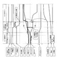
- FIG. 1 is a block diagram showing an internal configuration of a series / parallel HEV.
- a series / parallel HEV (hereinafter referred to as “hybrid vehicle”) shown in FIG. 1 includes a battery (BATT) 101, a temperature sensor (TEMP) 103, a converter (CONV) 105, and a first inverter (first INV) 107.
- the hybrid vehicle includes a sensor (not shown) such as a resolver that detects the rotational speed of the electric motor 109 and a sensor (not shown) such as a resolver that detects the rotational speed of the generator 113.
- the storage battery 101 has a plurality of storage cells connected in series, and supplies a high voltage of, for example, 100 to 200V.
- the storage cell is, for example, a lithium ion battery or a nickel metal hydride battery.
- the temperature sensor 103 detects the temperature of the battery 101 (hereinafter referred to as “battery temperature”). A signal indicating the battery temperature detected by the temperature sensor 103 is sent to the battery ECU 127.
- the converter 105 boosts or lowers the DC output voltage of the battery 101 while maintaining the direct current.
- the first inverter 107 converts a DC voltage into an AC voltage and supplies a three-phase current to the electric motor 109. Further, the first inverter 107 converts the AC voltage input during the regenerative operation of the electric motor 109 into a DC voltage and charges the battery 101.
- the electric motor 109 generates power for the hybrid vehicle to travel. Torque generated by the electric motor 109 is transmitted to the drive shaft 131 via the gear 119. Note that the rotor of the electric motor 109 is directly connected to the gear 119. In addition, the electric motor 109 operates as a generator during regenerative braking, and the electric power generated by the electric motor 109 is charged in the battery 101.
- the internal combustion engine 111 is used only for the generator 113 when the hybrid vehicle travels in series with the clutch 117 opened. However, when the clutch 117 is engaged, the output of the internal combustion engine 111 is transmitted to the drive shaft 131 via the generator 113, the clutch 117, and the gear 119 as mechanical energy for the hybrid vehicle to travel.
- the internal combustion engine 111 is directly connected to the rotor of the generator 113.
- the generator 113 generates electric power by the power of the internal combustion engine 111.
- the electric power generated by the generator 113 is charged in the battery 101 or supplied to the electric motor 109.
- the second inverter 115 converts the AC voltage generated by the generator 113 into a DC voltage.
- the electric power converted by the second inverter 115 is charged in the battery 101 or supplied to the electric motor 109 via the first inverter 107.
- the clutch 117 connects and disconnects the transmission path of the driving force from the internal combustion engine 111 to the driving wheel 133 based on an instruction from the management ECU 123.
- the hydraulic circuit 118 supplies a predetermined operating pressure to the clutch 117 via hydraulic oil.
- the gear 119 is a one-stage fixed gear corresponding to, for example, the fifth speed. Therefore, the gear 119 converts the driving force from the internal combustion engine 111 or the driving force from the electric motor 109 via the generator 113 into a rotation speed and torque at a specific gear ratio, and transmits them to the drive shaft 131.
- the vehicle speed sensor 121 detects the traveling speed (vehicle speed) of the hybrid vehicle. A signal indicating the vehicle speed detected by the vehicle speed sensor 121 is sent to the management ECU 123.
- the management ECU 123 calculates the required driving force based on the accelerator pedal opening (AP opening) and the vehicle speed according to the accelerator operation of the driver of the hybrid vehicle, the switching of the driving force transmission system, and the clutch 117 using the hydraulic circuit 118. Control regarding connection and disconnection, operation control of the internal combustion engine 111, and the like are performed. In FIG. 1, control of the internal combustion engine 111 by the management ECU 123 is indicated by a one-dot chain line. Details of the management ECU 123 will be described later.
- the motor ECU 125 controls the operation of the electric motor 109 or the generator 113 by switching control of the switching elements constituting the converter 105, the first inverter 107, and the second inverter 115, respectively.
- control of converter 105, first inverter 107, and second inverter 115 by motor ECU 125 is indicated by a one-dot chain line.
- the battery ECU 127 derives the remaining capacity (SOC: State of Charge) of the battery 101 based on the battery temperature obtained from the temperature sensor 103 and information such as the charge / discharge current and the terminal voltage of the battery 101.
- SOC State of Charge
- FIG. 2 is a diagram showing the internal configuration of the hydraulic circuit 118 and the relationship between the hydraulic circuit 118 and the clutch 117.
- the hydraulic circuit 118 supplies the hydraulic oil discharged from the oil tank 153 by the oil pump 151 to the clutch 117 via the regulator valve 155 and the two shift valves 157A and 157B.
- Shift valves 157A and 157B are provided on the pump oil passage from regulator valve 155 to clutch 117
- shift valve 157A is provided on the downstream side of the pump oil passage
- shift valve 157B is provided on the upstream side.
- the hydraulic circuit 118 includes a hydraulic switch 161A that detects opening / closing of the shift valve 157A and a hydraulic switch 161B that detects opening / closing of the shift valve 157B.
- the shift valve 157A is opened and closed by a shift solenoid 159A
- the shift valve 157B is opened and closed by a shift solenoid 159B.
- the shift solenoids 159A and 159B are each energized and controlled by the management ECU 123.
- the shift solenoid is energized, the shift valve is opened, and when the energization is stopped, the shift valve is closed.
- the shift solenoids 159A and 159B are energized, the shift valves 157A and 157B are opened, and the clutch 117 is engaged by the hydraulic oil pressure.
- FIG. 3 is a diagram schematically showing the main part of the drive system in the hybrid vehicle shown in FIG. Further, FIG. 4 shows transitions between driving states and driving modes when the hybrid vehicle is in (a) EV driving mode, (b) series driving mode, (c) engine driving mode, and (d) parallel driving mode.
- FIG. 4 shows transitions between driving states and driving modes when the hybrid vehicle is in (a) EV driving mode, (b) series driving mode, (c) engine driving mode, and (d) parallel driving mode.
- the clutch 117 is released and the internal combustion engine 111 is stopped.
- the hybrid vehicle travels by the driving force of the electric motor 109 that is driven by the power supply from the battery 101.
- the clutch 117 is disengaged, and the internal combustion engine is supplied to supply the electric power that the motor 109 can output the required driving force based on the AP opening, the vehicle speed, and the like.
- the engine 111 is operated.
- the hybrid vehicle travels by the driving force of the electric motor 109 that is driven by the power supply from the generator 113.
- the internal combustion engine 111 is driven at the operating point on the BSFC bottom line, and as shown by the one-dot chain line in FIG. Also good.
- auxiliary power from the battery 101 may be supplied to the electric motor 109.
- the clutch 117 is engaged, and the hybrid vehicle travels by the driving force of the internal combustion engine 111.
- the rotor of the electric motor 109 and the rotor of the generator 113 are rotated along with the driving of the internal combustion engine 111.
- the motor ECU 125 performs zero current control so that the generator 113 is in a no-load state.
- the internal combustion engine 111 is driven at the operating point on the BSFC bottom line, and is generated by the electric motor 109 driven as a generator, as indicated by a one-dot chain line in FIG.
- the stored power may be charged in the battery 101.
- the clutch 117 is engaged, and the hybrid vehicle travels by the driving force of both the internal combustion engine 111 and the electric motor 109.
- the rotor of the generator 113 is rotated along with the driving of the internal combustion engine 111.
- the second inverter 115 performs zero current control so that the generator 113 is in a no-load state.
- the clutch 117 is released and the EV traveling mode or the series traveling mode is set.
- the clutch 117 is engaged and set in the engine travel mode during medium-high speed steady travel (cruise travel), and the parallel travel mode is set during medium-high speed acceleration travel.
- the travel mode is set after the management ECU 123 shown in FIG. 1 determines the travel phase based on the accelerator pedal opening (AP opening), the vehicle speed, and the like. For example, when the travel phase changes from “low / medium speed acceleration travel” to “medium speed steady travel”, the management ECU 123 engages the clutch 117 and switches the travel mode from “series travel mode” to “engine travel mode”.
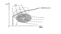
- FIG. 5 is a graph showing characteristics relating to the thermal efficiency of the internal combustion engine 111.
- the vertical axis of the graph indicates the torque of the internal combustion engine 111, and the horizontal axis indicates the rotational speed of the internal combustion engine 111.
- a thick solid line in FIG. 5 is a line connecting the operating points of the internal combustion engine 111 having the best fuel consumption rate (BSFC bottom line).
- the alternate long and short dash line in FIG. 5 is a line (equal output line) connecting the operating points of the internal combustion engine 111 that have the same output but different torque and rotational speed.
- the output energy of the internal combustion engine 111 is mechanical energy.
- the clutch 117 is disengaged, the mechanical energy output from the internal combustion engine 111 is converted into electrical energy by the generator 113 and then consumed for traveling.
- the energy transfer efficiency at this time is called “electric efficiency”, and the transmission form is called “electric transfer”.
- the clutch 117 is engaged, the mechanical energy output from the internal combustion engine 111 is consumed as it is for traveling through the generator 113 and the gear 119.
- the energy transmission efficiency at this time is called “mechanical efficiency”, and the transmission form is called “mechanical transmission”.
- a region 10 indicated by hatching in FIG. 5 is a region where the mechanical efficiency is better than the electrical efficiency as the transmission efficiency of the output energy of the internal combustion engine 111.
- FIG. 6 is a block diagram showing an internal configuration of the management ECU 123 that performs control to shift from the series travel mode to the engine direct travel.
- the management ECU 123 includes a required driving force deriving unit 501, an engine direct connection transition determining unit 503, a fastening rotation speed calculating unit 505, an internal combustion engine operation control unit 507, a hydraulic circuit control unit 509, A torque transition control unit 511.
- the required driving force deriving unit 501 derives the required driving force for the hybrid vehicle based on the AP opening and the vehicle speed.
- the torque in the drive shaft 131 obtained from the required drive force, the vehicle speed, etc. is referred to as “foot shaft torque”.
- the engine direct connection transition determination unit 503 determines whether or not to shift to the engine direct connection travel by engaging the clutch 117 based on the energy efficiency assumed when the hybrid vehicle travels to the engine direct travel while traveling in the series travel mode. Determine whether.
- the engagement rotation speed calculation unit 505 calculates the engagement rotation speed (clutch engagement rotation speed) of the internal combustion engine 111 that does not generate a shock even when the clutch 117 is engaged. In calculating the clutch engagement rotation speed, the engagement rotation speed calculation unit 505 calculates the rotation speed of the drive shaft 131 based on the vehicle speed and the radius of the drive wheel 133. From the rotational speed of the drive shaft 131 and the gear ratio of the gear 119, the rotational speed on the output side of the clutch 117 when the clutch 117 is engaged is calculated. In a state where the clutch 117 is engaged, the internal combustion engine 111 is connected to the clutch 117 via the rotor of the generator 113, and thus the calculated rotation speed is the “clutch engagement rotation speed”.
- the internal combustion engine operation control unit 507 generates power so that the rotational speed of the internal combustion engine 111 approaches the clutch engagement rotational speed before the clutch 117 is engaged when the engine direct connection transition determination section 503 determines the transition to the engine direct travel.
- the rotational speed of the internal combustion engine 111 is adjusted by controlling the torque of the machine 113.
- the hydraulic circuit control unit 509 outputs an open control signal for opening the shift valve 157B of the hydraulic circuit 118 when the engine direct connection shift determination unit 503 determines that the shift to the engine direct drive is performed.
- This open control signal is sent to the shift solenoid 159B of the hydraulic circuit 118.
- the shift solenoid 159B is energized by the open control signal, and the shift valve 157B is opened.
- the hydraulic circuit control unit 509 opens an open control signal for opening the shift valve 157A of the hydraulic circuit 118 when the differential rotational speed between the rotational speed of the internal combustion engine 111 and the clutch engagement rotational speed becomes a predetermined value or less. Is output.
- This open control signal is sent to the shift solenoid 159A of the hydraulic circuit 118.
- the shift solenoid 159A is energized by the open control signal, and the shift valve 157A is opened.
- the hydraulic circuit control unit 509 counts a predetermined time from the time when an opening control signal for opening the shift valve 157
- the torque transition control unit 511 determines that the engagement of the clutch 117 is completed because the operating pressure from the hydraulic circuit 118 to the clutch 117 has sufficiently increased.
- the torque transition control unit 511 that has determined that the engagement of the clutch 117 has been completed performs torque control of the electric motor 109 and the generator 113, thereby distributing the torque to the drive shaft 131 of the hybrid vehicle from the electric motor 109 to the internal combustion engine 111. Gradually move to.
- the internal combustion engine operation control unit 507 controls the torque of the internal combustion engine 111 to be constant while the torque transfer control by the torque transfer control unit 511 is being performed.
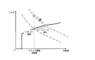
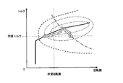
- FIG. 7 is a graph showing the transition of the operating point of the internal combustion engine 111 when shifting to engine direct travel when the rotational speed of the internal combustion engine 111 in the series travel mode is higher than the rotational speed when the clutch 117 is engaged. It is.
- the operating point A shown in FIG. 7 is an operating point of the internal combustion engine 111 when the hybrid vehicle is cruising or slowly accelerating in the series travel mode by the driving force from the electric motor 109 according to the accelerator operation of the driver.
- the rotational speed of the internal combustion engine 111 is reduced from this state to a value (clutch engagement rotational speed) indicated by a dotted line in FIG. 7 where no shock is generated even when the clutch 117 is engaged, the clutch follows the required driving force.
- the internal combustion engine operation control unit 507 of the management ECU 123 controls the torque of the generator 113 to decrease the rotational speed of the internal combustion engine 111.
- the hydraulic circuit control unit 509 of the management ECU 123 opens the shift valve 157A of the hydraulic circuit 118 to open the hydraulic circuit 118. To supply hydraulic oil to the clutch 117. At this time, even if the clutch 117 is engaged, no shock is generated, and the fuel consumption rate of the internal combustion engine 111 remains good.
- the internal combustion engine operation control unit 507 when the rotational speed of the internal combustion engine 111 is decreased to the clutch engagement rotational speed, the internal combustion engine operation control unit 507 causes the operating point of the internal combustion engine 111 to be in the BSFC bottom line as shown in FIG. The operation of the internal combustion engine 111 is controlled so as to shift from A to B along the line.
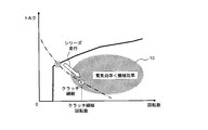
- FIG. 8 is a graph showing the transition of the operating point of the internal combustion engine 111 when shifting to engine direct travel when the rotational speed of the internal combustion engine 111 in the series travel mode is lower than the rotational speed when the clutch 117 is engaged. It is.
- An operating point D shown in FIG. 8 is an operating point of the internal combustion engine 111 when the hybrid vehicle is decelerated in the series travel mode by the driving force from the electric motor 109 according to the accelerator operation of the driver.
- the internal combustion engine operation control unit 507 of the management ECU 123 controls the torque of the generator 113 so that no shock is generated even when the clutch 117 is engaged (the value indicated by the dotted line in FIG. 8).
- the hydraulic circuit control unit 509 of the management ECU 123 opens the shift valve 157A of the hydraulic circuit 118 to open the hydraulic circuit 118.
- the internal combustion engine operation control unit 507 controls the internal combustion engine 111 to maintain an output corresponding to the required driving force during the transition of the operating point.
- the operating point of the internal combustion engine 111 deviates from the BSFC bottom line, so the fuel consumption rate decreases.
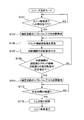
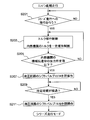
- FIG. 9 is a flowchart showing the operation of the management ECU 123 when shifting from the series travel mode to the engine direct travel.
- the hydraulic circuit control unit 509 shifts the hydraulic circuit 118.
- the valve 157B is opened (step S103).
- the engagement rotation speed calculation unit 505 calculates the clutch engagement rotation speed (step S105).
- the internal combustion engine operation control unit 507 controls the torque of the generator 113 to adjust the rotational speed of the internal combustion engine 111 (step S107).
- step S111 when the differential rotation speed between the rotation speed of the internal combustion engine 111 and the clutch engagement rotation speed is equal to or less than a predetermined value, the hydraulic circuit control unit 509 opens the shift valve 157A of the hydraulic circuit 118 (step S111). If the differential rotation speed exceeds a predetermined value, the process returns to step S105. When a predetermined time elapses from step S111, the torque transition control unit 511 determines that the engagement of the clutch 117 has been completed, and performs control to shift the torque to the drive shaft 131 of the hybrid vehicle from the electric motor 109 to the internal combustion engine 111. (Step S115).
- FIG. 10 is a timing chart at the time of shifting to direct engine travel during slow acceleration in the series travel mode when the rotational speed of the internal combustion engine 111 in the series travel mode is higher than the rotational speed when the clutch 117 is engaged. It is an example.
- FIG. 11 is a timing chart when shifting to the engine direct drive during deceleration in the series travel mode when the rotational speed of the internal combustion engine 111 in the series travel mode is higher than the rotational speed when the clutch 117 is engaged. It is an example.
- the management ECU 123 As described above, if the above-described control by the management ECU 123 is performed in the hybrid vehicle of the present embodiment, the occurrence of shock and efficiency (fuel consumption rate or total efficiency) when shifting from the series travel mode to the engine direct travel.
- the clutch can be engaged without lowering.
- FIG. 12 is a block diagram showing an internal configuration of the management ECU 123 that performs control for shifting from the engine direct traveling to the series traveling mode.
- the management ECU 123 includes a required driving force deriving unit 601, a series transition determining unit 603, an internal combustion engine operation control unit 605, a torque transition control unit 607, and a hydraulic circuit control unit 609.
- the required driving force deriving unit 601 derives the required driving force for the hybrid vehicle based on the AP opening and the vehicle speed.
- the torque in the drive shaft 131 obtained from the required drive force, the vehicle speed, etc. is referred to as “foot shaft torque”.
- the series transition determination unit 603 determines whether to shift to the series travel mode by releasing the clutch 117 based on the energy efficiency assumed when the hybrid vehicle transitions to the series travel mode while the engine is directly connected to the engine. To do.
- the internal combustion engine operation control unit 605 controls the torque of the generator 113 until the release of the clutch 117 is completed, thereby controlling the internal combustion engine 111. Control to keep the torque constant.
- the torque transition control unit 607 performs torque control of the electric motor 109 and the generator 113, thereby controlling the torque to the drive shaft 131 of the hybrid vehicle.
- the distribution is gradually shifted from the internal combustion engine 111 to the electric motor 109. That is, as the torque transition control unit 607 increases the torque of the generator 113, the generator 113 gradually absorbs the torque of the internal combustion engine 111 maintained constant, and at the same time, the torque transition control unit 607 By increasing the torque of the electric motor 109, the electric motor 109 outputs torque for the required driving force.
- the torque transition control unit 607 determines that the torque transition control has been completed when the difference between the foot shaft torque corresponding to the required driving force and the torque of the electric motor 109 is equal to or less than a predetermined value.
- the torque transition control unit 607 is configured to transmit the mechanical transmission component transmitted to the drive shaft 131 of the internal combustion engine 111 if the difference between the torque maintained constant of the internal combustion engine 111 and the torque of the generator 113 is equal to or less than a predetermined value. Is determined to be equal to or less than a predetermined value, and it is determined that the torque transfer is completed.
- the hydraulic circuit control unit 609 outputs a close control signal for closing the shift valve 157A of the hydraulic circuit 118 when the shift of the torque is completed after the shift to the series travel mode is determined by the series shift determining unit 603. To do.
- This closing control signal is sent to the shift solenoid 159A of the hydraulic circuit 118.
- the shift solenoid 159A is deenergized by the closing control signal, and the shift valve 157A is closed.
- the hydraulic circuit control unit 609 counts a predetermined time from the time when a closing control signal for closing the shift valve 157A is output. Further, when the predetermined time has been counted, the hydraulic circuit control unit 609 outputs a closing control signal for closing the shift valve 157B of the hydraulic circuit 118.
- This closing control signal is sent to the shift solenoid 159B of the hydraulic circuit 118.
- the shift solenoid 159B is deenergized by the closing control signal, and the shift valve 157B is closed.
- the management ECU 123 determines that the release of the clutch 117 is completed when the hydraulic circuit control unit 609 closes the shift valve 157B.
- the internal combustion engine operation control unit 605 does not change the generator 113 until the shift to the series travel mode is determined and the release of the clutch 117 is completed, that is, during the transition period from the engine direct connection travel to the series travel mode. Is controlled to maintain the torque of the internal combustion engine 111 constant. After the release of the clutch 117 is completed, the internal combustion engine operation control unit 605 prompts an increase in the output of the internal combustion engine 111 by slightly reducing the torque of the generator 113. As a result, both the torque and the rotational speed of the internal combustion engine 111 increase.
- FIG. 13 is an example of a timing chart when the hybrid vehicle shifts to the series travel mode during slow acceleration with direct engine travel.
- a change when the torque of the internal combustion engine 111 is not maintained constant during the transition period to the series travel mode is indicated by a two-dot chain line.
- the torque transition by the torque transition control unit 607 or the clutch 117 by the hydraulic circuit control unit 609 is performed. Even if the opening is performed, there is no unintentional vibration or the like, and a stable transition is performed.
- FIG. 14 is a flowchart showing the operation of the management ECU 123 when shifting from the engine directly connected running to the series running mode.
- the torque transition control unit 607 displays torque on the drive shaft 131 of the hybrid vehicle. Is controlled from the internal combustion engine 111 to the electric motor 109, and at the same time, the internal combustion engine operation control unit 605 performs control to maintain the torque of the internal combustion engine 111 constant (step S203).
- step S207 when the output of the mechanical transmission transmitted to the drive shaft 131 of the internal combustion engine 111 becomes a predetermined value or less, the hydraulic circuit control unit 609 closes the shift valve 157A of the hydraulic circuit 118 (step S207). If the output for machine transmission exceeds a predetermined value, the process returns to step S203. If the predetermined time has elapsed from step S207, it is determined that the release of the clutch 117 is completed, and the hydraulic circuit control unit 609 closes the shift valve 157B of the hydraulic circuit 118 (step S211).
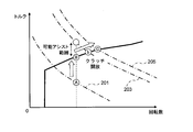
- FIG. 15 is a graph showing the transition of the operating point of the internal combustion engine 111 when the clutch 117 is released according to an increase in the required driving force.
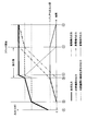
- FIG. 16 is a time chart showing changes in outputs when the clutch 117 is released according to an increase in the required driving force. In the graph of FIG. 16, it is assumed that there is no loss when energy is transmitted.
- the required output with the clutch 117 engaged is equal to the output indicated by the one-dot chain line of reference numeral 201, the internal combustion engine 111 is operated at the operating point A shown in FIG.
- the electric motor 109 is not driven.
- the management ECU 123 controls the internal combustion engine 111 to increase the torque while maintaining the rotation speed.
- the operating point of the internal combustion engine 111 changes from the operating point A upward in the graph of FIG.
- the upper limit of the operating point of the internal combustion engine 111 is set to the BSFC bottom line.
- the management ECU 123 increases the torque while maintaining the rotation speed and operates at the operating point B on the BSFC bottom line.
- the internal combustion engine 111 is controlled.
- the electric motor 109 is driven by power supply from the battery 101.
- the electric motor 109 may not be able to output the shortage. For example, if the remaining capacity (SOC: State of Charge) of the battery 101 is low, the battery 101 may not be able to supply the power required by the motor 109.
- the battery ECU 127 derives the output upper limit (battery output upper limit) of the battery 101 based on the SOC of the battery 101 and the battery temperature, and the management ECU 123 is insufficient within the range (possible assist range) that the motor 109 can output.
- the motor ECU 125 is instructed to output the minute amount by the electric motor 109.
- the SOC of the battery 101 is calculated by the battery ECU 127 based on the integrated value of the charge / discharge current of the battery 101 and the terminal voltage of the battery 101.
- the battery ECU 127 determines the lower value based on the relationship between the SOC and the battery output upper limit shown in FIG. 19A and the relationship between the battery temperature and the battery output upper limit shown in FIG. Derived as the output upper limit.
- the management ECU 123 performs control for shifting to series running.
- the management ECU 123 adjusts the outputs of the internal combustion engine 111, the generator 113, and the electric motor 109 while the clutch 117 is engaged, and then opens the clutch 117 and shifts to the series running.
- the management ECU 123 moves the operating point of the internal combustion engine 111 from the operating point B to the operating point b shown in FIG. 15 along the BSFC bottom line.
- the motor ECU 125 controls the second inverter 115 so that a part of the output of the internal combustion engine 111 that has been mechanically transmitted to the drive wheels 133 is used for power generation by the generator 113, and the machine of the output of the internal combustion engine 111. Increase the ratio of electrical transmission to transmission. That is, as shown in FIG. 16, the mechanical transmission output of the internal combustion engine 111 is gradually reduced, and the electrical transmission output is gradually increased.
- the electric transmission output of the internal combustion engine 111 is supplied to the generator 113, and the output (electric power) of the generator 113 is supplied to the electric motor 109. Therefore, each output of the generator 113 and the electric motor 109 increases as the output of the electric transmission increases.
- the management ECU 123 performs control to release the clutch 117.
- the electric power supplied to the electric motor 109 includes the output of the battery 101 in addition to the output of the generator 113.
- the management ECU 123 shifts the operating point of the internal combustion engine 111 to the operating point C shown in FIG. 15 so that all the electric power supplied to the electric motor 109 is output from the generator 113 after the clutch 117 is released, and The power supplied from the battery 101 to the electric motor 109 (output of the battery 101) is brought close to zero.
- FIG. 17 is a graph showing the transition of the operating point of the internal combustion engine 111 when the clutch 117 is released according to the change in the state of the battery 101.
- FIG. 18 is a time chart showing changes in each output when the clutch 117 is released according to a change in the state of the battery 101. In the graph of FIG. 18, it is assumed that there is no loss when energy is transmitted. In the initial state shown in FIG. 18, the internal combustion engine 111 is operated at the operating point D on the BSFC bottom line shown in FIG.
- the output upper limit (battery output upper limit) of the battery 101 decreases due to a decrease in SOC, a decrease in battery temperature, or the like, and the generator 113 cannot output the shortage.
- Battery ECU 127 derives the battery output upper limit based on the SOC of battery 101 and the battery temperature.
- the management ECU 123 engages the internal combustion engine with the clutch 117 engaged. While maintaining the operating point of the engine 111 at the operating point D on the BSFC bottom line, after adjusting the outputs of the generator 113 and the electric motor 109 as shown in FIG. 18, the clutch 117 is released to shift to the series running. .
- the management ECU 123 sets the output of the internal combustion engine 111 that has been mechanically transmitted to the drive wheels 133 to be used for power generation by the generator 113. 2
- the inverter 115 is controlled to increase the ratio of electrical transmission to mechanical transmission of the output of the internal combustion engine 111. That is, as shown in FIG. 18, the mechanical transmission output of the internal combustion engine 111 is gradually reduced, and the electrical transmission output is gradually increased.
- the electric transmission output of the internal combustion engine 111 is supplied to the generator 113, and the output (electric power) of the generator 113 is supplied to the electric motor 109. Therefore, each output of the generator 113 and the electric motor 109 increases as the output of the electric transmission increases.
- the output of the mechanical transmission of the internal combustion engine 111 becomes zero
- the output of the generator 113 becomes equal to the output of the internal combustion engine 111 and the output of the electric motor 109 becomes equal to the required driving force.
- the ECU 123 performs control for releasing the clutch 117.
- the electric power supplied to the electric motor 109 includes the output of the battery 101 in addition to the output of the generator 113.
- the management ECU 123 shifts the operating point of the internal combustion engine 111 to the operating point E shown in FIG. 17 so that all the electric power supplied to the electric motor 109 is output from the generator 113 after the clutch 117 is released, and The power supplied from the battery 101 to the electric motor 109 (output of the battery 101) is brought close to zero.
- the required driving force is increased by the increase in the required driving force or the lowering of the battery output upper limit.
- the internal combustion engine 111 and the electric motor 109 output a driving force equal to the required driving force when shifting to the series running because the total output of the above has been exceeded. Therefore, a shock does not occur when shifting from traveling using the internal combustion engine 111 to a series traveling, and the driver does not feel uncomfortable even when the clutch 117 is released. Further, since the battery 101 is not required to output more than the battery output upper limit, the battery 101 is properly used. Therefore, it is not necessary to use a large capacity battery only for a temporary situation. Further, since the internal combustion engine 111 in the transition period to the series running is operated at the operating point on the BSFC bottom line, there is no deterioration in fuel consumption.
Abstract
Description
図2は、油圧回路118の内部構成及び油圧回路118とクラッチ117との関係を示す図である。図2に示すように、油圧回路118は、オイルポンプ151によってオイルタンク153から吐出される作動油をレギュレータバルブ155及び2つのシフトバルブ157A,157Bを介してクラッチ117に給油する。シフトバルブ157A,157Bは、レギュレータバルブ155からクラッチ117までのポンプ油路上に設けられ、シフトバルブ157Aはポンプ油路の下流側に、シフトバルブ157Bは上流側に設けられている。なお、油圧回路118は、シフトバルブ157Aの開閉を検知する油圧スイッチ161Aと、シフトバルブ157Bの開閉を検知する油圧スイッチ161Bとを備える。 (Configuration of hydraulic circuit 118)
FIG. 2 is a diagram showing the internal configuration of the hydraulic circuit 118 and the relationship between the hydraulic circuit 118 and the clutch 117. As shown in FIG. 2, the hydraulic circuit 118 supplies the hydraulic oil discharged from the
図7は、シリーズ走行モード時の内燃機関111の回転数がクラッチ117を締結する際の回転数よりも高い場合に、エンジン直結走行へ移行する際の内燃機関111の運転点の推移を示すグラフである。図7に示される運転点Aは、ドライバのアクセル操作に応じた電動機109からの駆動力によってハイブリッド車両がシリーズ走行モードでクルーズ又は緩加速しているときの内燃機関111の運転点である。この状態から、クラッチ117を締結してもショックが発生しない図7中の点線で示される値(クラッチ締結回転数)まで内燃機関111の回転数を落とす際に、要求駆動力に追従してクラッチ117の出力側の出力を電動機109の出力と一致させると、内燃機関111の運転点は一点鎖線で示される等出力ラインに沿ってAからCに移る。この場合、運転点はBSFCボトムラインから外れるため、燃料消費率は低下する。 (Example 1)
FIG. 7 is a graph showing the transition of the operating point of the
図8は、シリーズ走行モード時の内燃機関111の回転数がクラッチ117を締結する際の回転数よりも低い場合に、エンジン直結走行へ移行する際の内燃機関111の運転点の推移を示すグラフである。図8に示される運転点Dは、ドライバのアクセル操作に応じた電動機109からの駆動力によってハイブリッド車両がシリーズ走行モードで減速しているときの内燃機関111の運転点である。本実施例では、マネジメントECU123の内燃機関運転制御部507が発電機113のトルクを制御して、クラッチ117を締結してもショックが発生しない図8中の点線で示される値(クラッチ締結回転数)まで内燃機関111の回転数を上げていく。内燃機関111の回転数とクラッチ締結回転数との差回転数が所定値以下になれば、マネジメントECU123の油圧回路制御部509は、油圧回路118のシフトバルブ157Aを開操作して、油圧回路118からクラッチ117へ作動油を供給するよう制御する。なお、本実施例では、内燃機関111の回転数をクラッチ締結回転数まで上げていくとき、要求駆動力が一定であれば、内燃機関運転制御部507は、図8に示すように、内燃機関111の運転点が一点鎖線で示される等出力ラインに沿ってDからEに推移するよう、内燃機関111の運転を制御する。すなわち、内燃機関運転制御部507は、運転点の推移中、内燃機関111が要求駆動力に応じた出力を維持するよう制御する。 (Example 2)
FIG. 8 is a graph showing the transition of the operating point of the
以下、図15及び図16を参照して、要求駆動力の増加に応じてクラッチ117を開放する際にマネジメントECU123が行う制御について説明する。図15は、要求駆動力の増加に応じてクラッチ117を開放する際の内燃機関111の運転点の推移を示すグラフである。図16は、要求駆動力の増加に応じてクラッチ117を開放する際の各出力の変化を示すタイムチャートである。なお、図16のグラフでは、エネルギーを伝達する際の損失はないものとする。クラッチ117が締結した状態での要求出力が符号201の一点鎖線で示される出力に等しいとき、内燃機関111は、図15に示される運転点Aで運転される。このとき、電動機109は駆動されていない。この状態からドライバのアクセル操作等のため要求駆動力が上がると、マネジメントECU123は、回転数を維持したままトルクを上げるよう内燃機関111を制御する。このとき内燃機関111の運転点は、運転点Aから図15のグラフにおける上方向に推移する。なお、内燃機関111の運転点の上限は、BSFCボトムラインに設定されている。 (Example 3)
Hereinafter, the control performed by the
以下、図17及び図18を参照して、蓄電器101の状態の変化に応じてクラッチ117を開放する際にマネジメントECU123が行う制御について説明する。図17は、蓄電器101の状態の変化に応じてクラッチ117を開放する際の内燃機関111の運転点の推移を示すグラフである。図18は、蓄電器101の状態の変化に応じてクラッチ117を開放する際の各出力の変化を示すタイムチャートである。なお、図18のグラフでは、エネルギーを伝達する際の損失はないものとする。図18に示す初期状態では、クラッチ117が締結した状態で、内燃機関111が図17に示されるBSFCボトムライン上の運転点Dで運転され、かつ、図17中の符号301の一点鎖線で示される要求駆動力に対して内燃機関111の出力が満たせない不足分(=要求駆動力-内燃機関111の出力)を蓄電器101からの電力供給によって電動機109が出力するよう制御されている。このとき、SOCの低下やバッテリ温度の低下等によって蓄電器101の出力上限(バッテリ出力上限)が低下して、発電機113が上記不足分を出力できない場合があり得る。 Example 4
Hereinafter, with reference to FIGS. 17 and 18, the control performed by the
103 温度センサ(TEMP)
105 コンバータ(CONV)
107 第1インバータ(第1INV)
109 電動機(MOT)
111 内燃機関(ENG)
113 発電機(GEN)
115 第2インバータ(第2INV)
117 クラッチ
118 油圧回路
119 ギアボックス
121 車速センサ
123 マネジメントECU(FI/MG ECU)
125 モータECU(MOT/GEN ECU)
127 バッテリECU(BATT ECU)
131 駆動軸
133 駆動輪
501 要求駆動力導出部
503 エンジン直結移行判断部
505 締結回転数算出部
507 内燃機関運転制御部
509 油圧回路制御部
511 トルク移行制御部
601 要求駆動力導出部
603 シリーズ移行判断部
605 内燃機関運転制御部
607 トルク移行制御部
609 油圧回路制御部 101 Battery (BATT)
103 Temperature sensor (TEMP)
105 Converter (CONV)
107 1st inverter (1st INV)
109 Motor (MOT)
111 Internal combustion engine (ENG)
113 Generator (GEN)
115 2nd inverter (2nd INV)
117 Clutch 118
125 Motor ECU (MOT / GEN ECU)
127 Battery ECU (BATT ECU)
131
Claims (10)
- 内燃機関と、
前記内燃機関の駆動によって発電する発電機と、
電動機に電力を供給する蓄電器と、
駆動輪に接続され、前記蓄電器及び前記発電機の少なくとも一方からの電力供給によって駆動する前記電動機と、
前記発電機と前記駆動輪の間に配置され、前記内燃機関から前記発電機を介した前記駆動輪までの動力の伝達経路を断接する動力伝達断接部と、を備え、前記電動機及び前記内燃機関の少なくとも一方からの動力によって走行するハイブリッド車両であって、
当該ハイブリッド車両が前記内燃機関の動力による前記発電機の発電電力によって駆動される前記電動機を駆動源としたシリーズ走行から、前記動力伝達断接部を締結して、当該ハイブリッド車両が少なくとも前記内燃機関を駆動源としたエンジン直結走行へ移行するかを判断するエンジン直結移行判断部と、
前記走行速度に応じた前記動力伝達断接部の前記駆動輪側の回転数を、前記動力伝達断接部を締結する前記内燃機関の締結回転数として導出する締結回転数導出部と、
前記内燃機関の運転を制御する内燃機関制御部と、
前記エンジン直結移行判断部が前記エンジン直結走行へ移行すると判断した後、前記内燃機関の回転数と前記締結回転数との差回転数が所定値以下になったとき、前記動力伝達断接部を締結するよう制御する断接制御部と、
を備えたことを特徴とするハイブリッド車両。 An internal combustion engine;
A generator for generating electric power by driving the internal combustion engine;
A battery for supplying electric power to the motor;
The electric motor connected to a drive wheel and driven by power supply from at least one of the capacitor and the generator;
A power transmission connecting / disconnecting portion that is disposed between the generator and the drive wheel and connects / disconnects a power transmission path from the internal combustion engine to the drive wheel via the generator, the motor and the internal combustion engine A hybrid vehicle that travels with power from at least one of the engines,
The hybrid vehicle is connected at least to the internal combustion engine by fastening the power transmission connecting / disconnecting portion from a series running using the electric motor driven by the electric power generated by the generator by the power of the internal combustion engine as a drive source. An engine direct connection transition determination unit that determines whether or not to shift to engine direct travel using a power source,
A fastening rotational speed deriving unit for deriving the rotational speed of the drive wheel side of the power transmission connecting / disconnecting part according to the traveling speed as a fastening rotational speed of the internal combustion engine for fastening the power transmission connecting / disconnecting part;
An internal combustion engine controller for controlling the operation of the internal combustion engine;
After determining that the engine direct connection transition determination unit shifts to the engine direct connection traveling, when the difference rotational speed between the rotational speed of the internal combustion engine and the fastening rotational speed becomes a predetermined value or less, the power transmission connecting / disconnecting section is A connection / disconnection control unit for controlling to be fastened;
A hybrid vehicle characterized by comprising: - 請求項1に記載のハイブリッド車両であって、
当該ハイブリッド車両が所定車速以上で前記シリーズ走行時の前記内燃機関の回転数が前記締結回転数よりも高いとき、前記内燃機関制御部は、燃料消費率が最も良い運転点を結んだ燃費最良ライン上で前記内燃機関を運転するよう制御することを特徴とするハイブリッド車両。 The hybrid vehicle according to claim 1,
When the hybrid vehicle is above a predetermined vehicle speed and the rotational speed of the internal combustion engine when traveling in the series is higher than the fastening rotational speed, the internal combustion engine control unit is configured to connect the best fuel consumption line with the operating point with the best fuel consumption rate. A hybrid vehicle characterized by controlling the internal combustion engine to operate. - 請求項1に記載のハイブリッド車両であって、
当該ハイブリッド車両におけるアクセル操作に応じたアクセルペダル開度及び当該ハイブリッド車両の走行速度に基づいて、当該ハイブリッド車両に要求される駆動力を導出する要求駆動力導出部を備え、
当該ハイブリッド車両が所定車速以上で前記シリーズ走行時の前記内燃機関の回転数が前記締結回転数よりも低いとき、前記内燃機関制御部は、前記要求駆動力導出部が導出した要求駆動力に応じた出力を維持可能な運転点を結んだ等出力ライン上で前記内燃機関を運転するよう制御することを特徴とするハイブリッド車両。 The hybrid vehicle according to claim 1,
A required driving force deriving unit for deriving a driving force required for the hybrid vehicle based on an accelerator pedal opening corresponding to an accelerator operation in the hybrid vehicle and a traveling speed of the hybrid vehicle;
When the hybrid vehicle is at a predetermined vehicle speed or higher and the rotational speed of the internal combustion engine when traveling in the series is lower than the fastening rotational speed, the internal combustion engine control unit responds to the required driving force derived by the required driving force deriving unit. A hybrid vehicle, wherein the internal combustion engine is controlled to operate on an equal output line connecting operating points capable of maintaining the output. - 請求項3に記載のハイブリッド車両であって、
前記内燃機関の運転点が前記等出力ライン上を移行して、前記内燃機関の回転数が前記締結回転数と一致した運転点における、前記内燃機関から前記駆動輪へのエネルギー伝達効率は、電気効率よりも機械効率の方が良いことを特徴とするハイブリッド車両。 The hybrid vehicle according to claim 3,
The energy transfer efficiency from the internal combustion engine to the drive wheels at the operating point at which the operating point of the internal combustion engine moves on the equal output line and the rotational speed of the internal combustion engine matches the fastening rotational speed is A hybrid vehicle characterized by better mechanical efficiency than efficiency. - 内燃機関と、
前記内燃機関の駆動によって発電する発電機と、
電動機に電力を供給する蓄電器と、
駆動輪に接続され、前記蓄電器及び前記発電機の少なくとも一方からの電力供給によって駆動する前記電動機と、
前記発電機と前記駆動輪の間に配置され、前記内燃機関から前記発電機を介した前記駆動輪までの動力の伝達経路を断接する動力伝達断接部と、を備え、前記電動機及び前記内燃機関の少なくとも一方からの動力によって走行するハイブリッド車両であって、
当該ハイブリッド車両が少なくとも前記内燃機関を駆動源としたエンジン直結走行から、前記動力伝達断接部を開放して、当該ハイブリッド車両が前記内燃機関の動力による前記発電機の発電電力によって駆動される前記電動機を駆動源としたシリーズ走行へ移行するかを判断するシリーズ移行判断部と、
前記内燃機関の出力の機械伝達に対する電気伝達の比率を変更する伝達比率変更部と、
前記シリーズ移行判断部が前記シリーズ走行へ移行すると判断した後、前記内燃機関の機械伝達分の出力が所定値以下になったとき、前記動力伝達断接部を開放するよう制御する断接制御部と、
を備えたことを特徴とするハイブリッド車両。 An internal combustion engine;
A generator for generating electric power by driving the internal combustion engine;
A battery for supplying electric power to the motor;
The electric motor connected to a drive wheel and driven by power supply from at least one of the capacitor and the generator;
A power transmission connecting / disconnecting portion that is disposed between the generator and the drive wheel and connects / disconnects a power transmission path from the internal combustion engine to the drive wheel via the generator, the motor and the internal combustion engine A hybrid vehicle that travels with power from at least one of the engines,
The hybrid vehicle is driven by the power generated by the generator by the power of the internal combustion engine by opening the power transmission connecting / disconnecting portion from at least the engine directly connected running using the internal combustion engine as a drive source. A series transition determination unit that determines whether to shift to a series run using an electric motor as a drive source;
A transmission ratio changing unit for changing a ratio of electrical transmission to mechanical transmission of the output of the internal combustion engine;
A connection / disconnection control unit that controls to open the power transmission connection / disconnection part when the output of the mechanical transmission of the internal combustion engine becomes equal to or less than a predetermined value after the series transition determination part determines that the series traveling is to be performed. When,
A hybrid vehicle characterized by comprising: - 請求項5に記載のハイブリッド車両であって、
前記蓄電器から前記電動機への電力供給を制御する蓄電器出力制御部と、
前記内燃機関の運転を制御する内燃機関制御部と、を備え、
前記動力伝達断接部が開放された後、
前記蓄電器出力制御部は、前記蓄電器から前記電動機への供給電力を低減し、
前記内燃機関制御部は、前記蓄電器から前記電動機への供給電力の低減に応じて前記内燃機関の出力が増すよう、燃料消費率が最も良い運転点を結んだ燃費最良ライン上で前記内燃機関を運転することを特徴とするハイブリッド車両。 The hybrid vehicle according to claim 5,
A capacitor output controller for controlling power supply from the capacitor to the electric motor;
An internal combustion engine control unit for controlling the operation of the internal combustion engine,
After the power transmission / disconnection portion is opened,
The capacitor output control unit reduces power supplied from the capacitor to the electric motor,
The internal combustion engine control unit controls the internal combustion engine on a fuel efficiency best line connecting an operating point with the best fuel consumption rate so that an output of the internal combustion engine increases in accordance with a reduction in power supplied from the capacitor to the electric motor. A hybrid vehicle characterized by driving. - 請求項5に記載のハイブリッド車両であって、
当該ハイブリッド車両におけるアクセル操作に応じたアクセルペダル開度及び当該ハイブリッド車両の走行速度に基づいて、当該ハイブリッド車両に要求される駆動力を導出する要求駆動力導出部と、
前記内燃機関の運転を制御する内燃機関制御部と、を備え、
前記動力伝達断接部が締結された状態で当該ハイブリッド車両が前記内燃機関を駆動源とした走行時に前記要求駆動力導出部が導出した要求駆動力が上がると、前記内燃機関制御部は、前記要求駆動力を満たすよう、燃料消費率が最も良い運転点を結んだ燃費最良ラインに運転点が到達するまでは前記内燃機関の出力を上げ、
前記要求駆動力が前記燃費最良ライン上の運転点での前記内燃機関の出力を超える場合には、前記内燃機関制御部は、前記燃費最良ライン上の運転点で前記内燃機関を運転し、前記蓄電器からの電力供給によって駆動する前記電動機が、前記要求駆動力に対する前記内燃機関の出力不足分を出力するようことを特徴とするハイブリッド車両。 The hybrid vehicle according to claim 5,
A required driving force deriving unit for deriving a driving force required for the hybrid vehicle based on an accelerator pedal opening corresponding to an accelerator operation in the hybrid vehicle and a traveling speed of the hybrid vehicle;
An internal combustion engine control unit for controlling the operation of the internal combustion engine,
When the required driving force derived by the required driving force deriving unit increases when the hybrid vehicle travels using the internal combustion engine as a driving source in a state where the power transmission connecting / disconnecting unit is fastened, the internal combustion engine control unit Increase the output of the internal combustion engine until the driving point reaches the fuel efficiency best line connecting the driving point with the best fuel consumption rate so as to satisfy the required driving force,
When the required driving force exceeds the output of the internal combustion engine at the operating point on the fuel efficiency best line, the internal combustion engine control unit operates the internal combustion engine at the operating point on the fuel efficiency best line, The hybrid vehicle, wherein the electric motor driven by supplying electric power from a battery outputs an output shortage of the internal combustion engine with respect to the required driving force. - 請求項5に記載のハイブリッド車両であって、
前記内燃機関の運転を制御する内燃機関制御部を備え、
前記伝達比率変更部による前記内燃機関の出力の機械伝達に対する電気伝達の比率の変更開始から前記伝達経路の開放が完了するまでの間、前記内燃機関制御部は、前記発電機のトルクを制御して、前記内燃機関のトルクを一定に維持するよう前記内燃機関の運転を制御することを特徴とするハイブリッド車両。 The hybrid vehicle according to claim 5,
An internal combustion engine controller for controlling the operation of the internal combustion engine,
The internal combustion engine control unit controls the torque of the generator from the start of changing the ratio of electrical transmission to the mechanical transmission of the output of the internal combustion engine by the transmission ratio changing unit until the opening of the transmission path is completed. And controlling the operation of the internal combustion engine to maintain a constant torque of the internal combustion engine. - 内燃機関と、
前記内燃機関の駆動によって発電する発電機と、
電動機に電力を供給する蓄電器と、
駆動輪に接続され、前記蓄電器及び前記発電機の少なくとも一方からの電力供給によって駆動する前記電動機と、
前記発電機と前記駆動輪の間に配置され、前記内燃機関から前記発電機を介した前記駆動輪までの動力の伝達経路を断接する動力伝達断接部と、を備え、前記電動機及び前記内燃機関の少なくとも一方からの動力によって走行するハイブリッド車両の制御方法であって、
前記ハイブリッド車両が前記内燃機関の動力による前記発電機の発電電力によって駆動される前記電動機を駆動源としたシリーズ走行から、前記動力伝達断接部を締結して、前記ハイブリッド車両が少なくとも前記内燃機関を駆動源としたエンジン直結走行へ移行するかを判断し、
前記走行速度に応じた前記動力伝達断接部の前記駆動輪側の回転数を、前記動力伝達断接部を締結する前記内燃機関の締結回転数として導出し、
前記エンジン直結走行へ移行すると判断した後、前記内燃機関の運転を制御して、前記内燃機関の回転数と前記締結回転数との差回転数が所定値以下になったとき、前記動力伝達断接部を締結するよう制御することを特徴とするハイブリッド車両の制御方法。 An internal combustion engine;
A generator for generating electric power by driving the internal combustion engine;
A battery for supplying electric power to the motor;
The electric motor connected to a drive wheel and driven by power supply from at least one of the capacitor and the generator;
A power transmission connecting / disconnecting portion that is disposed between the generator and the drive wheel and connects / disconnects a power transmission path from the internal combustion engine to the drive wheel via the generator, the motor and the internal combustion engine A method for controlling a hybrid vehicle that travels by power from at least one of an engine,
The hybrid vehicle is connected at least to the internal combustion engine by fastening the power transmission connecting / disconnecting part from a series running using the electric motor driven by the electric power generated by the generator by the power of the internal combustion engine as a drive source. To determine whether to shift to engine direct drive with
Deriving the rotational speed on the drive wheel side of the power transmission connecting / disconnecting portion according to the traveling speed as the fastening rotational speed of the internal combustion engine that fastens the power transmission connecting / disconnecting portion;
After determining to shift to the engine direct running, the operation of the internal combustion engine is controlled, and when the differential rotational speed between the rotational speed of the internal combustion engine and the fastening rotational speed is equal to or less than a predetermined value, the power transmission disconnection is performed. A control method for a hybrid vehicle, wherein the control is performed so that the contact portion is fastened. - 内燃機関と、
前記内燃機関の駆動によって発電する発電機と、
電動機に電力を供給する蓄電器と、
駆動輪に接続され、前記蓄電器及び前記発電機の少なくとも一方からの電力供給によって駆動する前記電動機と、
前記発電機と前記駆動輪の間に配置され、前記内燃機関から前記発電機を介した前記駆動輪までの動力の伝達経路を断接する動力伝達断接部と、を備え、前記電動機及び前記内燃機関の少なくとも一方からの動力によって走行するハイブリッド車両の制御方法であって、
前記ハイブリッド車両が少なくとも前記内燃機関を駆動源としたエンジン直結走行から、前記動力伝達断接部を開放して、前記ハイブリッド車両が前記内燃機関の動力による前記発電機の発電電力によって駆動される前記電動機を駆動源としたシリーズ走行へ移行するかを判断し、
前記内燃機関の出力の機械伝達に対する電気伝達の比率を変更し、
前記シリーズ走行へ移行すると判断した後、前記内燃機関の機械伝達分の出力が所定値以下になったとき、前記動力伝達断接部を開放するよう制御することを特徴とするハイブリッド車両の制御方法。 An internal combustion engine;
A generator for generating electric power by driving the internal combustion engine;
A battery for supplying electric power to the motor;
The electric motor connected to a drive wheel and driven by power supply from at least one of the capacitor and the generator;
A power transmission connecting / disconnecting portion that is disposed between the generator and the drive wheel and connects / disconnects a power transmission path from the internal combustion engine to the drive wheel via the generator, the motor and the internal combustion engine A method for controlling a hybrid vehicle that travels by power from at least one of an engine,
The hybrid vehicle is driven by the generated power of the generator by the power of the internal combustion engine by opening the power transmission / disconnection portion from at least the engine directly connected running using the internal combustion engine as a drive source. Judge whether to shift to series running with an electric motor as the drive source,
Changing the ratio of electrical transmission to mechanical transmission of the output of the internal combustion engine;
A control method for a hybrid vehicle, characterized in that, when it is determined to shift to the series travel, when the output of the mechanical transmission of the internal combustion engine becomes equal to or less than a predetermined value, control is performed to open the power transmission connection / disconnection portion. .
Priority Applications (7)
| Application Number | Priority Date | Filing Date | Title |
|---|---|---|---|
| CA2895657A CA2895657A1 (en) | 2013-01-11 | 2013-01-11 | Hybrid vehicle and method for controlling same |
| CN201380069994.6A CN104918811A (en) | 2013-01-11 | 2013-01-11 | Hybrid vehicle and method for controlling same |
| MYPI2015702256A MY174902A (en) | 2013-01-11 | 2013-01-11 | Hybrid vehicle and method for controlling same |
| EP13871270.8A EP2944496A4 (en) | 2013-01-11 | 2013-01-11 | Hybrid vehicle and method for controlling same |
| PCT/JP2013/050492 WO2014109064A1 (en) | 2013-01-11 | 2013-01-11 | Hybrid vehicle and method for controlling same |
| US14/759,601 US9457798B2 (en) | 2013-01-11 | 2013-01-11 | Hybrid vehicle and method for controlling same |
| JP2013524285A JPWO2014109064A1 (en) | 2013-01-11 | 2013-01-11 | Hybrid vehicle and control method thereof |
Applications Claiming Priority (1)
| Application Number | Priority Date | Filing Date | Title |
|---|---|---|---|
| PCT/JP2013/050492 WO2014109064A1 (en) | 2013-01-11 | 2013-01-11 | Hybrid vehicle and method for controlling same |
Publications (1)
| Publication Number | Publication Date |
|---|---|
| WO2014109064A1 true WO2014109064A1 (en) | 2014-07-17 |
Family
ID=51166731
Family Applications (1)
| Application Number | Title | Priority Date | Filing Date |
|---|---|---|---|
| PCT/JP2013/050492 WO2014109064A1 (en) | 2013-01-11 | 2013-01-11 | Hybrid vehicle and method for controlling same |
Country Status (6)
| Country | Link |
|---|---|
| US (1) | US9457798B2 (en) |
| EP (1) | EP2944496A4 (en) |
| JP (1) | JPWO2014109064A1 (en) |
| CN (1) | CN104918811A (en) |
| CA (1) | CA2895657A1 (en) |
| WO (1) | WO2014109064A1 (en) |
Cited By (7)
| Publication number | Priority date | Publication date | Assignee | Title |
|---|---|---|---|---|
| DE102015222694A1 (en) * | 2015-11-17 | 2017-05-18 | Volkswagen Aktiengesellschaft | Operating a drive device of a hybrid vehicle and hybrid vehicle |
| WO2019093894A2 (en) | 2017-11-10 | 2019-05-16 | 1E Taraz Holding B.V. | Hybrid power train arrangement for a vehicle |
| JP2020131880A (en) * | 2019-02-18 | 2020-08-31 | 日産自動車株式会社 | Control method for electric vehicle and drive system of electric vehicle |
| JP2021133871A (en) * | 2020-02-28 | 2021-09-13 | 本田技研工業株式会社 | Vehicle control device |
| JP2021133872A (en) * | 2020-02-28 | 2021-09-13 | 本田技研工業株式会社 | Vehicle control device |
| CN114802193A (en) * | 2021-01-28 | 2022-07-29 | 本田技研工业株式会社 | Vehicle control device |
| JP2022136811A (en) * | 2021-03-08 | 2022-09-21 | 本田技研工業株式会社 | Vehicle control device |
Families Citing this family (14)
| Publication number | Priority date | Publication date | Assignee | Title |
|---|---|---|---|---|
| WO2014024317A1 (en) * | 2012-08-10 | 2014-02-13 | トヨタ自動車株式会社 | Alternator controller |
| JPWO2014109063A1 (en) * | 2013-01-11 | 2017-01-19 | 本田技研工業株式会社 | Hybrid vehicle and control method thereof |
| JP6183409B2 (en) * | 2015-05-26 | 2017-08-23 | トヨタ自動車株式会社 | Hybrid vehicle |
| DE102017205871A1 (en) * | 2017-04-06 | 2018-10-11 | Volkswagen Aktiengesellschaft | Method for compensating for idling losses in an electric vehicle, computer program product, data carrier and electric vehicle |
| JP6879382B2 (en) * | 2017-12-15 | 2021-06-02 | 日産自動車株式会社 | Hybrid vehicle control method and control device |
| JP6988913B2 (en) * | 2017-12-15 | 2022-01-05 | 日産自動車株式会社 | Hybrid vehicle control method and hybrid vehicle control device |
| CN108327512A (en) * | 2018-02-09 | 2018-07-27 | 浙江吉利控股集团有限公司 | Hybrid electric drive system and vehicle |
| US10543739B1 (en) * | 2018-07-25 | 2020-01-28 | Fca Us Llc | Mode transition control techniques for an electrically all-wheel drive hybrid vehicle |
| US10826415B2 (en) * | 2018-09-06 | 2020-11-03 | Pratt & Whitney Canada Corp. | Operation of a hybrid electric aircraft propulsion system |
| JP7056537B2 (en) * | 2018-12-12 | 2022-04-19 | トヨタ自動車株式会社 | Hybrid vehicle |
| CN111762014A (en) * | 2019-04-02 | 2020-10-13 | 联合汽车电子有限公司 | Hybrid power system, hybrid power automobile and method for controlling vehicle operation |
| JP7059313B2 (en) * | 2020-03-17 | 2022-04-25 | 本田技研工業株式会社 | Vehicle control device |
| US11097721B1 (en) * | 2020-03-31 | 2021-08-24 | Ford Global Technologies, Llc | Methods and system for modulating torque during a transmission gear shift |
| CN116472192B (en) * | 2020-10-28 | 2024-03-08 | 日产自动车株式会社 | Hybrid vehicle control method and hybrid vehicle |
Citations (6)
| Publication number | Priority date | Publication date | Assignee | Title |
|---|---|---|---|---|
| JPH0352753B2 (en) | 1984-09-26 | 1991-08-12 | Sophia Co Ltd | |
| JPH09224304A (en) | 1996-02-19 | 1997-08-26 | Hitachi Ltd | Hybrid automobile |
| JP2011074483A (en) | 2009-09-07 | 2011-04-14 | Fujimi Inc | Powder for thermal spraying |
| JP2011074482A (en) | 2009-09-04 | 2011-04-14 | Hitachi Metals Ltd | Plating device |
| WO2011074482A1 (en) * | 2009-12-16 | 2011-06-23 | 本田技研工業株式会社 | Hybrid vehicle and method for controlling same |
| WO2011074483A1 (en) * | 2009-12-16 | 2011-06-23 | 本田技研工業株式会社 | Hybrid vehicle and control method thereof |
Family Cites Families (10)
| Publication number | Priority date | Publication date | Assignee | Title |
|---|---|---|---|---|
| JP3052753B2 (en) | 1994-09-29 | 2000-06-19 | トヨタ自動車株式会社 | Control device for series parallel composite electric vehicle |
| FR2777232A1 (en) * | 1998-04-10 | 1999-10-15 | Renault | TRACTION DEVICE FOR HYBRID ELECTRIC VEHICLE |
| JP3480316B2 (en) * | 1998-06-15 | 2003-12-15 | 日産自動車株式会社 | Control device for hybrid vehicle |
| JP3454172B2 (en) | 1998-11-04 | 2003-10-06 | 日産自動車株式会社 | Hybrid vehicle control method |
| JP2001233070A (en) | 2000-02-21 | 2001-08-28 | Jatco Transtechnology Ltd | Parallel hybrid vehicle driving device |
| DE102005033723A1 (en) * | 2005-07-15 | 2007-02-01 | Daimlerchrysler Ag | Drive train and method for controlling an Antriesstranges |
| JP5151160B2 (en) * | 2007-01-26 | 2013-02-27 | トヨタ自動車株式会社 | Control device for vehicle drive device |
| DE102008053505B4 (en) * | 2008-10-28 | 2023-10-05 | Volkswagen Ag | Method for controlling a hybrid powertrain of a motor vehicle |
| TWI413593B (en) * | 2008-11-28 | 2013-11-01 | Ind Tech Res Inst | Series and parallel coupling control system adapted to hybrid vehicle and method therefor |
| JP5338743B2 (en) * | 2010-04-15 | 2013-11-13 | 三菱自動車工業株式会社 | Hybrid car |
-
2013
- 2013-01-11 JP JP2013524285A patent/JPWO2014109064A1/en active Pending
- 2013-01-11 CN CN201380069994.6A patent/CN104918811A/en active Pending
- 2013-01-11 CA CA2895657A patent/CA2895657A1/en not_active Abandoned
- 2013-01-11 EP EP13871270.8A patent/EP2944496A4/en not_active Withdrawn
- 2013-01-11 US US14/759,601 patent/US9457798B2/en active Active
- 2013-01-11 WO PCT/JP2013/050492 patent/WO2014109064A1/en active Application Filing
Patent Citations (6)
| Publication number | Priority date | Publication date | Assignee | Title |
|---|---|---|---|---|
| JPH0352753B2 (en) | 1984-09-26 | 1991-08-12 | Sophia Co Ltd | |
| JPH09224304A (en) | 1996-02-19 | 1997-08-26 | Hitachi Ltd | Hybrid automobile |
| JP2011074482A (en) | 2009-09-04 | 2011-04-14 | Hitachi Metals Ltd | Plating device |
| JP2011074483A (en) | 2009-09-07 | 2011-04-14 | Fujimi Inc | Powder for thermal spraying |
| WO2011074482A1 (en) * | 2009-12-16 | 2011-06-23 | 本田技研工業株式会社 | Hybrid vehicle and method for controlling same |
| WO2011074483A1 (en) * | 2009-12-16 | 2011-06-23 | 本田技研工業株式会社 | Hybrid vehicle and control method thereof |
Non-Patent Citations (1)
| Title |
|---|
| See also references of EP2944496A4 * |
Cited By (14)
| Publication number | Priority date | Publication date | Assignee | Title |
|---|---|---|---|---|
| DE102015222694A1 (en) * | 2015-11-17 | 2017-05-18 | Volkswagen Aktiengesellschaft | Operating a drive device of a hybrid vehicle and hybrid vehicle |
| WO2019093894A2 (en) | 2017-11-10 | 2019-05-16 | 1E Taraz Holding B.V. | Hybrid power train arrangement for a vehicle |
| JP2020131880A (en) * | 2019-02-18 | 2020-08-31 | 日産自動車株式会社 | Control method for electric vehicle and drive system of electric vehicle |
| JP7298179B2 (en) | 2019-02-18 | 2023-06-27 | 日産自動車株式会社 | Electric vehicle control method and electric vehicle drive system |
| JP7075958B2 (en) | 2020-02-28 | 2022-05-26 | 本田技研工業株式会社 | Vehicle control device |
| US11230282B2 (en) | 2020-02-28 | 2022-01-25 | Honda Motor Co., Ltd. | Control device of vehicle |
| JP2021133872A (en) * | 2020-02-28 | 2021-09-13 | 本田技研工業株式会社 | Vehicle control device |
| JP7075957B2 (en) | 2020-02-28 | 2022-05-26 | 本田技研工業株式会社 | Vehicle control device |
| JP2021133871A (en) * | 2020-02-28 | 2021-09-13 | 本田技研工業株式会社 | Vehicle control device |
| CN114802193A (en) * | 2021-01-28 | 2022-07-29 | 本田技研工业株式会社 | Vehicle control device |
| JP2022115746A (en) * | 2021-01-28 | 2022-08-09 | 本田技研工業株式会社 | Vehicle control device |
| JP7280902B2 (en) | 2021-01-28 | 2023-05-24 | 本田技研工業株式会社 | vehicle controller |
| JP2022136811A (en) * | 2021-03-08 | 2022-09-21 | 本田技研工業株式会社 | Vehicle control device |
| JP7240430B2 (en) | 2021-03-08 | 2023-03-15 | 本田技研工業株式会社 | vehicle controller |
Also Published As
| Publication number | Publication date |
|---|---|
| JPWO2014109064A1 (en) | 2017-01-19 |
| US9457798B2 (en) | 2016-10-04 |
| CN104918811A (en) | 2015-09-16 |
| CA2895657A1 (en) | 2014-07-17 |
| EP2944496A1 (en) | 2015-11-18 |
| US20150353075A1 (en) | 2015-12-10 |
| EP2944496A4 (en) | 2016-10-12 |
Similar Documents
| Publication | Publication Date | Title |
|---|---|---|
| WO2014109064A1 (en) | Hybrid vehicle and method for controlling same | |
| JP5624996B2 (en) | Hybrid vehicle and control method thereof | |
| JP5624995B2 (en) | Hybrid vehicle and control method thereof | |
| US7267191B2 (en) | System and method for battery protection strategy for hybrid electric vehicles | |
| EP2559577B1 (en) | Hybrid automobile | |
| CN109624962B (en) | Hybrid vehicle | |
| WO2014109063A1 (en) | Hybrid vehicle and control method therefor | |
| CN103380047B (en) | The driving control device of motor vehicle driven by mixed power | |
| JP5447534B2 (en) | Control device for vehicle power transmission device | |
| US11142202B2 (en) | Control system for hybrid vehicle | |
| US9724992B2 (en) | Hybrid vehicle | |
| JP5729475B2 (en) | Vehicle and vehicle control method | |
| JP2017154637A (en) | Motorcar | |
| WO2013065166A1 (en) | Vehicle and vehicle control method | |
| JP2011225079A (en) | Hybrid automobile | |
| JP2011073533A (en) | Control device for vehicle | |
| JP6636840B2 (en) | Hybrid vehicle control device and hybrid vehicle system | |
| JP2016132263A (en) | Hybrid automobile | |
| JP5941973B2 (en) | Hybrid vehicle and control method thereof | |
| US10730508B2 (en) | Hybrid vehicle and control method for hybrid vehicle | |
| WO2014038442A1 (en) | Hybrid vehicle control apparatus | |
| WO2013137213A1 (en) | Device for controlling hybrid vehicle | |
| JP2021020631A (en) | Hybrid vehicle | |
| JP2011225077A (en) | Hybrid automobile |
Legal Events
| Date | Code | Title | Description |
|---|---|---|---|
| ENP | Entry into the national phase |
Ref document number: 2013524285 Country of ref document: JP Kind code of ref document: A |
|
| 121 | Ep: the epo has been informed by wipo that ep was designated in this application |
Ref document number: 13871270 Country of ref document: EP Kind code of ref document: A1 |
|
| ENP | Entry into the national phase |
Ref document number: 2895657 Country of ref document: CA |
|
| REEP | Request for entry into the european phase |
Ref document number: 2013871270 Country of ref document: EP |
|
| WWE | Wipo information: entry into national phase |
Ref document number: 14759601 Country of ref document: US Ref document number: 2013871270 Country of ref document: EP |
|
| NENP | Non-entry into the national phase |
Ref country code: DE |