WO2014109043A1 - 風力発電装置 - Google Patents
風力発電装置 Download PDFInfo
- Publication number
- WO2014109043A1 WO2014109043A1 PCT/JP2013/050353 JP2013050353W WO2014109043A1 WO 2014109043 A1 WO2014109043 A1 WO 2014109043A1 JP 2013050353 W JP2013050353 W JP 2013050353W WO 2014109043 A1 WO2014109043 A1 WO 2014109043A1
- Authority
- WO
- WIPO (PCT)
- Prior art keywords
- hub
- pump
- wind power
- wind turbine
- generator according
- Prior art date
- Legal status (The legal status is an assumption and is not a legal conclusion. Google has not performed a legal analysis and makes no representation as to the accuracy of the status listed.)
- Ceased
Links
Images



Classifications
-
- F—MECHANICAL ENGINEERING; LIGHTING; HEATING; WEAPONS; BLASTING
- F03—MACHINES OR ENGINES FOR LIQUIDS; WIND, SPRING, OR WEIGHT MOTORS; PRODUCING MECHANICAL POWER OR A REACTIVE PROPULSIVE THRUST, NOT OTHERWISE PROVIDED FOR
- F03D—WIND MOTORS
- F03D9/00—Adaptations of wind motors for special use; Combinations of wind motors with apparatus driven thereby; Wind motors specially adapted for installation in particular locations
- F03D9/20—Wind motors characterised by the driven apparatus
- F03D9/28—Wind motors characterised by the driven apparatus the apparatus being a pump or a compressor
-
- F—MECHANICAL ENGINEERING; LIGHTING; HEATING; WEAPONS; BLASTING
- F03—MACHINES OR ENGINES FOR LIQUIDS; WIND, SPRING, OR WEIGHT MOTORS; PRODUCING MECHANICAL POWER OR A REACTIVE PROPULSIVE THRUST, NOT OTHERWISE PROVIDED FOR
- F03D—WIND MOTORS
- F03D15/00—Transmission of mechanical power
-
- F—MECHANICAL ENGINEERING; LIGHTING; HEATING; WEAPONS; BLASTING
- F05—INDEXING SCHEMES RELATING TO ENGINES OR PUMPS IN VARIOUS SUBCLASSES OF CLASSES F01-F04
- F05B—INDEXING SCHEME RELATING TO WIND, SPRING, WEIGHT, INERTIA OR LIKE MOTORS, TO MACHINES OR ENGINES FOR LIQUIDS COVERED BY SUBCLASSES F03B, F03D AND F03G
- F05B2260/00—Function
- F05B2260/40—Transmission of power
- F05B2260/406—Transmission of power through hydraulic systems
-
- Y—GENERAL TAGGING OF NEW TECHNOLOGICAL DEVELOPMENTS; GENERAL TAGGING OF CROSS-SECTIONAL TECHNOLOGIES SPANNING OVER SEVERAL SECTIONS OF THE IPC; TECHNICAL SUBJECTS COVERED BY FORMER USPC CROSS-REFERENCE ART COLLECTIONS [XRACs] AND DIGESTS
- Y02—TECHNOLOGIES OR APPLICATIONS FOR MITIGATION OR ADAPTATION AGAINST CLIMATE CHANGE
- Y02E—REDUCTION OF GREENHOUSE GAS [GHG] EMISSIONS, RELATED TO ENERGY GENERATION, TRANSMISSION OR DISTRIBUTION
- Y02E10/00—Energy generation through renewable energy sources
- Y02E10/70—Wind energy
- Y02E10/72—Wind turbines with rotation axis in wind direction
-
- Y—GENERAL TAGGING OF NEW TECHNOLOGICAL DEVELOPMENTS; GENERAL TAGGING OF CROSS-SECTIONAL TECHNOLOGIES SPANNING OVER SEVERAL SECTIONS OF THE IPC; TECHNICAL SUBJECTS COVERED BY FORMER USPC CROSS-REFERENCE ART COLLECTIONS [XRACs] AND DIGESTS
- Y02—TECHNOLOGIES OR APPLICATIONS FOR MITIGATION OR ADAPTATION AGAINST CLIMATE CHANGE
- Y02P—CLIMATE CHANGE MITIGATION TECHNOLOGIES IN THE PRODUCTION OR PROCESSING OF GOODS
- Y02P80/00—Climate change mitigation technologies for sector-wide applications
- Y02P80/10—Efficient use of energy, e.g. using compressed air or pressurized fluid as energy carrier
Definitions
- the present invention relates to a wind power generator that transmits rotational energy of a rotor as pressure through a medium and performs power generation operation using the pressure, and particularly relates to installation of a pump that converts rotational energy into pressure. is there.
- a wind turbine generator is a device that generates electric power by converting wind kinetic energy into rotational energy of a rotor, and further using the rotational energy of the rotor to generate a generator.
- Patent Document 1 describes a wind power generation system including a hydraulic transmission including a hydraulic pump attached adjacent to a main shaft and a hydraulic motor driven by the hydraulic oil of the hydraulic pump.
- a wind power generation system including a hydraulic transmission including a hydraulic pump attached adjacent to a main shaft and a hydraulic motor driven by the hydraulic oil of the hydraulic pump.
- the main shaft connected to the rotor is rotated by the rotation of the rotor, and the hydraulic pump is driven by the rotation of the main shaft. Then, pressure oil is fed from the hydraulic pump to the hydraulic motor, and the generator is rotated by the rotation of the hydraulic motor to generate power.
- Patent Document 1 includes a hub and a main shaft disposed outside the hub, and includes a hydraulic pump on the outer diameter side of the main shaft. Therefore, the total length of the hub, the main shaft and the pump is increased, leading to an increase in weight, and as a result, it is necessary to improve the strength of the members that support them. There is not enough consideration.
- an object of the present invention is to provide a wind turbine generator that can improve reliability or economy.
- a wind turbine generator includes a blade that rotates by receiving wind, a hub that supports the blade and rotates together with the blade, and an internal component that accompanies the rotation of the blade.
- a pump capable of changing pressure, and a generator for generating electricity based on the pressure change generated from the pump, wherein the pump is at least partly disposed in the hub and is internalized as the hub rotates. It is a pump which raises the pressure of.
- FIG. 1 is an overall perspective view showing the external appearance and overall outline of a wind turbine generator 100 according to this embodiment.
- FIG. 2 is a side cross-sectional view of the wind power generation apparatus 100 of FIG. 1 cut along a plane including the center axis 4a of the tower 4 and the rotation axis 9 of the rotor 1, as viewed from the side.
- the blade 1b and the tower 4 are partially omitted, and the swivel joint 13, the hydraulic pump 7, the generator 8, and the like are partially omitted from the internal structure.
- a wind turbine generator 100 includes a rotor 1 that rotates by receiving wind, a support member 2 that rotatably supports the rotor 1, and a support member 2 inside.
- the nacelle 10 to be accommodated, the spinner cover 11 that accommodates the hub 1a connected to the nacelle 10 and arranged at the rotation center of the rotor 1, and supports the load of the blade (indirectly), and supports the support member 2 to the base portion 3
- the hydraulic pump 5 attached to both the rotor 1 and the support member 2, the hydraulic pipe 6 for transporting the pressure oil discharged by the operation of the hydraulic pump 5, and the hydraulic pipe 6
- the hydraulic motor 7 and the generator 8 are provided inside the tower 4 having a hollow structure and fixed to the base portion 3. Further, a member that accommodates the hub inside and is rotatably supported with respect to the tower is referred to as a housing portion, and the nacelle 10 and the spinner cover 11 correspond to this housing portion in this specification.
- the rotor 1 includes three blades 1 b and a hub 1 a that rotates together with the blade 1 b and rotatably supports the blade 1 b, and each blade 1 b is around a rotation axis 9 of the rotor 1. Are attached radially. The force generated by the wind striking the blade 1b from the direction of the rotating shaft 9 of the rotor 1 is converted into power for rotating the rotor 1.
- the outer shape of the hub 1 a is a hollow cylindrical shape having a thickness and a shape in which an opening on the side away from the tower 4 is closed.
- a mounting portion 1aa for mounting a plurality of blades 1b is provided on the outer diameter side of the hollow cylindrical shape, and a mounting portion 1ab protruding toward the inner diameter side and a hydraulic pressure so that a support member 2 can be mounted inside the hollow portion.
- Mounting portions 1ac that protrude toward the inner diameter side are provided inside the cylindrical shape so that the pump 5 can be mounted.
- the attachment portion 1aa is connected to each blade 1b.
- the mounting portion 1ab is fixed to the support member 2 through a bearing.
- both bearings 12a and 12b are fixed to a shaft portion 2a which is a small-diameter portion described below, and the hydraulic pump 5 has a larger outer diameter.
- the bearing mounting portion 1ab protrudes more toward the inner diameter side than the mounting portion 1ac (pump mounting portion) fixed to the hydraulic pump 5.
- the pump mounting portion is provided at a position closer to the tower than each bearing mounting portion.
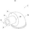
- FIG. 3 is a perspective view of the support member 2.
- the support member 2 supports the shaft portion 2a (which becomes a small diameter portion) and the shaft portion 2a and has an outer diameter perpendicular to the rotation axis of the rotor 1 (or the hub 1a) larger than the shaft portion 2a ( That is, the support portion 2b (which has a large diameter portion) is integrally formed.
- the support portion 2 b of the support member 2 is supported at a predetermined height on the tower 4 via the yaw bearing 14.
- the support member 2 By being supported on the tower 4 via the yaw bearing 14, the support member 2 can freely rotate in the horizontal plane around the tower center axis 4a in accordance with the wind direction (on the tower 4).
- the nacelle 10 is connected to the support portion 2 b of the support member 2, and is supported at a predetermined height on the tower 4 via the yaw bearing 14 in the same manner as the support member 2. That is, the nacelle 10 can also freely rotate in the horizontal plane around the tower central axis 4a according to the wind direction (on the tower 4).
- the tower 4 and the support portion 2b have a hollow structure, and an operator can access the inside of the nacelle 10 from the tower 4 through the inside of the support member 2. Since the inside of the tower 4 has a hollow structure, it is possible to provide hydraulic piping 6 that transmits power from the nacelle 10 to the base 3 and a lifting device such as a ladder or an elevator for an operator to access the nacelle 10. .
- the shaft portion 2a has a hollow cylindrical shape, and is provided so as to protrude from the support portion 2b to the outside of the nacelle 10 and to the inside of the hub 1a.
- the inside of the tower 4, the inside of the support portion 2b, the inside of the shaft portion 2a, and the inside of the hub 1a are in communication.
- a pipe through which the medium whose pressure has been changed by the pump passes can be arranged in the hollow portion.
- the wiring can be passed into the hub 1a through the hollow portion (communication), and the worker can access the hub 1a during maintenance.
- the central axis 2e of the shaft portion 2a coincides with the rotating shaft 9 of the rotor 1 (or hub 1a) and is provided parallel to the horizontal direction or inclined by about 1 to 10 ° from the horizontal direction.
- the term “parallel” with respect to the rotation axis includes not only parallel to the horizontal direction but also a direction inclined by about 1 to 10 ° from the horizontal direction.
- the shaft portion 2a and the support portion 2b have a spread in a direction perpendicular to the central axis 2e, and the support portion 2b serving as the large diameter portion has an outer diameter that is greater than the position where the shaft portion 2a serving as the small diameter portion is provided.
- the side 2c is provided.
- the rotor 1 that is, the hub 1 a to which the blade 1 b is attached is connected to the shaft portion 2 a through the hydraulic pump 5 and the bearings 12 a and 12 b, and the shaft portion 2 a has the weight itself. Both the load applied to the hub 1a (ie, the rotor 1) by the wind is supported. Further, as shown in FIG. 2, a pipe portion 15 may be formed on the shaft portion 2a, whereby the pressure oil can be fed into the support portion 2b without leakage.
- the foundation 3 is provided on the ground, the surface of the sea, the surface of the lake, or the river in order to fix and support the tower 4 (hereinafter referred to as the ground as a representative, but similarly installed on the surface of the sea, the surface of the lake, or the river. Is also possible).
- the foundation 3 may be fixedly provided on the ground, the seabed, the lake bottom, the riverbed, or the like, or when the water depth is deep, a floating body may be provided on the water surface and the foundation may be fixed to the floating body.
- the tower 4 supports the nacelle 10 including the rotor 1 and the support member 2 that supports them at a certain height, and has a cylindrical hollow structure.
- the lower end portion (root) of the tower 4 is fixed to the base portion 3
- the upper end portion (tip end) of the tower 4 is connected to the center of the tower 4 through the yaw bearing 14 in accordance with the wind direction.
- the shaft 4a is rotatably supported.
- members connected to each other such as the support member 2, the hub 1 a, and the spinner cover 11 also rotate around the central axis 4 a of the tower 4.
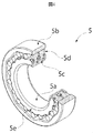
- FIG. 4 is an example of the hydraulic pump 5 used in the present embodiment, and is a partially cutaway perspective view partially cut away for explaining the internal structure.
- the type and configuration of the hydraulic pump 5 are not particularly limited to those described in each embodiment, but in the hydraulic pump 5 in this embodiment, a radial piston hydraulic pump having an inner member 5a and an outer member 5b. Is used.
- the outer member 5b uses a ring cam provided with a plurality of undulations (cam lobes) so that the inner diameter side of the cylindrical member is continuously waved between the small diameter portion and the large diameter portion.
- a plurality of cylinders 5c are provided radially and are manifolds that connect them inside.
- a plurality of pistons 5d that move up and down along the cylinder 5c are formed between the inner member 5a and the outer member 5b.
- a plurality of cylinders 5c and pistons 5d arranged in the circumferential direction are provided in the direction of the rotation axis of the hydraulic pump. Further, both the low-pressure oil and high-pressure oil inlets are provided in the inner member 5a.
- the hydraulic pump 5 including the inner member 5a and the outer member 5b may fix the inner member 5a and rotate the outer member 5b. Conversely, the outer member 5b is fixed and the inner member 5a is rotated. Also good.
- the hydraulic pipe 6 is made of a material that can withstand high pressure with increased strength in order to send high-pressure oil pressured by the hydraulic pump 5 without leakage.
- the piping part 15 is formed in the supporting member 2, the junction part of the said piping part 15 and other piping will not be ask
- the hydraulic motor 7 and the generator 8 are provided inside the tower 4 having a hollow structure and fixed to the base portion 3, but their positions are not particularly limited. .
- it may be fixedly provided inside the tower 4 or may be fixedly provided on the base portion 3 outside the tower 4.
- a member for supporting these members may be provided in the nacelle 10 and installed in the nacelle 10. That is, in the configuration of the present embodiment, power transmission can be performed by the hydraulic transmission, and therefore the positions of the hydraulic motor 7 and the generator 8 connected thereto are not particularly limited.
- the swivel joint 13 is used to connect the hydraulic pipe 6 rotatably.
- the hydraulic pipe 6 drawn into the tower 4 through the swivel joint 13 is fixed by a member 4 b to be supported by the wall surface of the tower 4, and feeds oil to the hydraulic motor 7 in the base portion 3. I do.
- the hydraulic piping 6 can be firmly supported even when a fluctuating load such as pulsation generated in the hydraulic system occurs.
- the rotor 1 including the blade 1b and the hub 1a is rotated by receiving wind.
- the rotor 1 is connected to an outer member 5 b of the hydraulic pump 5 and rotates together with the rotor 1.
- the high-pressure oil having pressure energy is fed to the hydraulic motor 7 through the hydraulic pipe 6, and the hydraulic motor 7 converts the pressure energy into rotational energy and rotates the output member of the hydraulic motor.
- oil is returned to the inlet of the hydraulic pump 5 through the hydraulic pipe 6.
- the generator 8 joined to the output member of the hydraulic motor 7 receives rotational energy from its input shaft, and the rotational energy is converted into electric energy (by rotating the rotor in the generator 8). To generate electricity.
- the hydraulic pump 5 is installed in the hub 1a.
- the shaft portion 2 a of the support member 2 that supports the hydraulic pump 5 fixes and supports the inner member 5 a of the hydraulic pump 5, and the outer member 5 b of the hydraulic pump 5 is connected to the hub 1 a and rotates with the rotation of the rotor 1.
- a member for supporting the hydraulic pump in the nacelle and a member for transmitting the rotational power from the rotor to the hydraulic pump are separately required.
- This member requires a length corresponding to the distance from the hub to the support portion in the nacelle or the hydraulic pump. Therefore, as a result of increasing the length, an increase in weight is caused, and as a result, it is necessary to improve the strength of the member supporting them.
- the hydraulic pump 5 since the hydraulic pump 5 is installed in the hub 1a, the total length of the combination of the hub 1a and the hydraulic pump 5 is shortened and can be installed compactly. Further, since the hydraulic pump (outer member 5b) is directly connected to the hub 1a, it is not necessary to provide any new power transmission member. Furthermore, as shown in FIG. 2, since the hydraulic pump 5 is in the hub 1a, a sufficient space for installing other components in the nacelle 10 can be secured. As other components, for example, a hydraulic motor 7 and a generator 8 are conceivable. Even if these are installed in the nacelle 10, the total length can be kept short because the hydraulic pump 5 is not arranged in the nacelle 10. It becomes possible. Therefore, the place to install is not limited, and the members that support these can be compact and lightweight.
- the swivel joint 13 is used when it is necessary to relieve the stress generated in the connection portion due to rotation, but the oil sent to the ground is about 10 to several tens of megapascals. Therefore, a large thrust load is applied to the swivel joint 13 in the direction of the central axis 4 a of the tower 4.
- the swivel joint 13 is firmly fixed to the support member 2 and the tower 4 respectively, and a space for arranging a member for firmly fixing is required.
- a space for firmly fixing a part of the swivel joint 13 in the support member 2 is also secured.
- the shaft portion 2a of the support member 2 can be shortened, and the weight of the support member 2 can be reduced.
- the hydraulic pump 5, which is a heavy load is arranged facing (adjacent) the shaft portion 2a and the support portion 2b (the coupling portion 2d, described in FIG. 3) Therefore, the distance from the coupling part 2d to the heavy object is reduced, and the bending moment applied to the coupling part 2d is reduced. Thereby, the support member 2 can be reduced in weight.
- the support portion 2b has a larger diameter
- the hydraulic pump 5 faces the support portion 2b and is fixed to the support portion.
- the side surface 5c (shown in FIG. 4) of the inner member 5a of the hydraulic pump 5 is fastened and fixed to the surface 2c (shown in FIG. 3) provided on the support portion 2b. Since the hydraulic pump 5 faces the support portion 2b and the hydraulic pump 5 is fixed by the support portion 2b, the area and location to be supported increase, and the load due to the strong torque due to the increase in size is supported by the support member 2. Can be dispersed and supported at a plurality of locations.
- the rotor 1 is rotationally supported by the support member 2, and a bearing 12 for rotationally supporting the rotor 1 may be provided between the rotor 1 and the support member 2.
- a bearing 12 for rotationally supporting the rotor 1 may be provided between the rotor 1 and the support member 2.
- two bearings 12a and 12b are provided to stably support the rotor 1, and the center of gravity of the rotor 1 is between the two bearings 12a and 12b (including the case where any bearing position and the center of gravity overlap each other).
- the bearings are arranged so as to be the same in the following embodiments).
- the number of these bearings in the axial direction may be one or a plurality.
- the bearings 12 a and 12 b support the weight of the rotor 1, the load in the bending direction and the load in the thrust direction due to wind, and can transmit only the rotational torque to the outer member 5 b of the hydraulic pump 5. Therefore, the durability and reliability of the hydraulic pump 5 can be improved without applying a load in the bending direction or the thrust direction to the hydraulic pump 5.
- the hydraulic pump 5 is provided at a position closer to the support portion 2b, which is the larger diameter portion of the support member 2, than any of the bearings 12a and 12b, the hydraulic pump 5 is connected to the nacelle when the wind power generator 100 is assembled.
- the hub 1a that is, the rotor 1 can be assembled after being attached to the support member 2 protruding from the inside, and the assemblability can be improved.
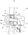
- Example 2 will be described with reference to FIG.
- the arrangement of the hydraulic pump and the bearing in the first embodiment is changed, and the same reference numerals as those shown in FIGS.
- the description of the structure and the part having the same function is omitted. It goes without saying that portions having the same configuration and function have the same effects as described above.
- a bearing 22a provided in the shaft portion 21a of the support member 21 and a bearing provided in the support portion 21b of the support member 21 inside the hub 1a.
- the hydraulic pump 25 is provided between these two bearings using 22b.
- the support member 21 supports the shaft portion 21a (which becomes a small diameter portion) and the shaft portion 21a, and has an outer diameter perpendicular to the rotation axis of the rotor 1 (or the hub 1a) than the shaft portion 21a.
- a large support portion 21b (that is, a large diameter portion) is integrally formed.
- a shaft portion 21a to which the bearing 22a is attached and a part of the support portion 21b to which the bearing 22b is attached protrude from the nacelle 10, and the bearing 22b is from the nacelle 10 of the support portion 21b. It is provided in the protruding portion and supports the hub 1a.
- a bearing having a large outer diameter can be used by fixing the bearing 22b to the support portion 21b having a larger outer diameter perpendicular to the rotational axis direction of the hub 1a than the shaft portion 21a.
- the pump mounting portion fixed to the hydraulic pump protrudes to the inner diameter side than the bearing mounting portion fixed to the bearing 22b, and further the bearing mounting fixed to the bearing 22a than the pump mounting portion.
- the part protrudes to the inner diameter side. And a pump attachment part is provided between each bearing attachment part. Since the bearing having a large outer diameter can disperse the load, it is more reliable and durable. As a result, since the bearing is fixed to the support portion 21b having an outer diameter larger than that of the shaft portion 21a, reliability and durability can be improved.
- the center of gravity of the rotor 1 is located between the two bearings 22a and 22b in order to stably support the rotor 1. Therefore, it is necessary to provide a certain distance between the bearings 22a and 22b.
- the shaft length of the shaft portion 21a of the support member 21 that supports the bearings 22a and 22b is increased as much as the interval L. In this embodiment, however, the shaft length of the shaft portion 21a can be shortened by using the support portion 21b of the support member 21 and providing the support portion 21b with the bearing 22b. Therefore, the support member 2 can be reduced in weight.
- bearings having an outer diameter smaller than the outer diameter of the hydraulic pump 25 are arranged on both sides of the hydraulic pump 25, when the hydraulic pump 25 is attached to or removed from the inside of the hub 1a, the bearing and one of the hubs that support the bearing are supported. It is necessary to remove the member.
- a bearing 22b that is disposed closer to the tower 4 in the direction of the rotation axis of the hub than the hydraulic pump 25 is provided in the support portion 21b, and the outer diameter of the bearing 22b is the outer diameter of the hydraulic pump 25. Since it is larger, the hub 1a can be attached after the hydraulic pump 25 is attached to the shaft portion 21a of the support member 21, and the assemblability can be improved.
- Example 3 will be described with reference to FIG.
- the hydraulic pump 5 of the first embodiment is attached to the tip of the shaft portion 2a of the support member 2, and the positions of the bearings 32a and 32b are changed.
- the wind power generator 300 of FIG. 6 the description of the components having the same functions as those of the configurations denoted by the same reference numerals shown in the already described drawings is omitted. It goes without saying that portions having the same configuration and function have the same effects as described above.
- bearings 32a and 32b are provided on the shaft portion 31a of the support member 31 inside the hub 41a.
- a bearing closer to the end face 31f far from the support portion 31b is referred to as 32a
- a bearing closer to the support portion 31b is referred to as 32b.
- a hydraulic pump 35 is provided on the shaft portion 31a between the end face 31f and the bearing 32a.
- both bearings 32a and 32b are fixed to a shaft portion that is a small diameter portion, and the hydraulic pump has a larger outer diameter. It protrudes to the inner diameter side from the pump mounting portion fixed to the hydraulic pump.
- the pump mounting portion is provided at a position farther from the tower than each bearing mounting portion.
- the hub 41a is provided with an opening 41ad that allows the hydraulic pump 35 to be carried out of the hub 41a at a position farther from the tower 4 than the bearings 32a and 32b.
- the spinner cover 42 is provided with an opening 42a and an opening / closing part 42b from which the hydraulic pump 35 can be removed.
- both the opening 41ad and the opening 42a are formed larger than the outer diameter of the hydraulic pump 35 in the direction perpendicular to the rotation axis direction of the hub 41a.
- the spinner cover 42 is included in the accommodating portion together with the nacelle 10, but the opening 42a communicates with the opening 41ad when the hydraulic pump 35 is carried out by opening the opening / closing portion 42b. Therefore, by opening the opening / closing part 42b, the hydraulic pump 35 can be carried out from the hub 41a and the housing part while the rotor 41 is attached to the support member 31.
- the hub 41a is provided with an opening 41ad that enables the hydraulic pump 35 to be carried out of the hub 41a at a position farther from the tower 4 than the bearings 32a and 32b.
- the hydraulic pump 35 can be removed without removing the heavy rotor 41, and the hydraulic pump 35 can be easily lowered and repaired at low cost.
- the hub 41a when the hub 41a is arranged in the accommodating portion as in the present embodiment, it is formed so as to be able to communicate with the opening 41ad when the hydraulic pump 35 is carried out, and the hydraulic pump 35 is connected to the tower more than the bearings 32a and 32b.
- the opening 42a By forming the opening 42a in the housing so that it can be carried out from the housing at a position away from 4, the hydraulic pump 35 can be removed without removing the rotor 41, which is also a heavy object. Become.
- the opening / closing part 42 is provided in the present embodiment, the case where the opening / closing part 42 is provided has been described.
- the present invention is not limited to this, and the opening provided in the housing part when the pump is carried out communicates with the opening provided in the hub. If it can form, it can be substituted.
- the opening for carrying out the hydraulic pump 35 is larger than the outer diameter of the hydraulic pump 35 in the direction perpendicular to the rotation axis direction of the hub.
- the hydraulic pump 35 can be carried out if it is longer than the length of the hydraulic pump 35 in the rotation axis direction of the hub. It suffices to provide an opening that can carry the hydraulic pump 35 out of the hub 41a in any direction.
- the hydraulic pump 35 is disposed closest to the end face 31f. Without removing (that is, without removing the hub 41a, that is, the rotor 41), the hydraulic pump 35 can be detached from the shaft portion 31a.
- the present invention is not limited to the hydraulic pump, and any medium that can convert rotational energy into fluid energy may be used.
- air pressure instead of oil pressure.
Landscapes
- Engineering & Computer Science (AREA)
- Life Sciences & Earth Sciences (AREA)
- Sustainable Development (AREA)
- Sustainable Energy (AREA)
- Chemical & Material Sciences (AREA)
- Combustion & Propulsion (AREA)
- Mechanical Engineering (AREA)
- General Engineering & Computer Science (AREA)
- Power Engineering (AREA)
- Wind Motors (AREA)
Abstract
本発明は信頼性または経済性を向上させた風力発電装置を提供することを目的としており、当該目的に基づき、本発明に係る風力発電装置は、風を受けて回転するブレードと、該ブレードを支持し、かつ該ブレードと共に回転するハブと、前記ブレードの回転に伴い内部の圧力を変化させられるポンプと、該ポンプから生ずる圧力変化に基づいて発電運転する発電機を備え、前記ポンプは、前記ハブ内に少なくとも一部が配置されると共に、前記ハブの回転に伴って内部の圧力を高めるポンプであることを特徴とする。
Description
本発明は、ロータの回転エネルギーを、媒体を介して圧力として伝達し、当該圧力を用いて発電運転する風力発電装置に関するものであり、特に回転エネルギーを圧力に変換するポンプの設置等に関するものである。
近年、発電装置として風のエネルギーを利用した風力発電装置が急速に普及してきている。風力発電装置は、風の運動エネルギーをロータの回転エネルギーに変換し、さらにロータの回転エネルギーを用いて発電機を発電運転させ、電力を発生する装置である。
従来、このような風力発電装置では、風により回転せしめられるロータの回転数が、発電を行う発電機の定格回転数に比べて小さいため、ロータと発電機の間に機械式(歯車式)の増速機を設けることにより、発電機の定格回転数まで増速し、発電機に入力されるようになっていた。
また近年、発電効率の向上を目的に、風力発電装置の大型化・大出力化が進んでおり、これに伴って、ロータ自体の重量と伝達するトルクが増大し、これらを支持・伝達する支持部材及び増速機の構造複雑化と重量増大が加速し、コストが増大する傾向にある。
さらに大型化・大出力化により、風による変動荷重も強大なものとなり、増速機、支持部材やこれらの支持構造は強大な変動荷重に対応する強度を確保するためには、重量が増大し、コストが増大する。
特にブレードの強度や、風力発電装置の発生する騒音に大きく関わる翼端速度の上昇を抑制する目的から、大型化(ロータ大径化)に伴い、ロータの回転数を低下させる傾向がある。大出力化に加えて、このようなロータの回転数低下により、ロータから増速機へ伝達されるトルクが飛躍的に増加する傾向にある。このような大トルクを伝達し得る機械式の増速機は複雑で大型かつ大重量なものとなることが予測される。
このため、機械式の増速機に代わる新しい動力伝達装置として、油圧トランスミッションを採用した風力発電システムがあり、例えば特許文献1に記載されている。
特許文献1には、主軸に隣接して取り付けられた油圧ポンプと、油圧ポンプの圧油により駆動される油圧モータとからなる油圧トランスミッションを備えた風力発電システムが記載されている。該風力発電システムでは、ロータの回転によりロータに接続された主軸を回転させ、主軸の回転により油圧ポンプを駆動する。そして、該油圧ポンプから油圧モータへ圧油が送油され、この油圧モータの回転により発電機を回転し、発電を行っている。
しかしながら、上記特許文献1の構造は、ハブとハブの外側に配置される主軸とを備えており、当該主軸の外径側に油圧ポンプを備えるものである。従って、ハブ、主軸及びポンプを組合わせた全長が長くなってしまい、重量の増大を招き、結果としてそれらを支持する部材の強度を向上させる必要になる等、信頼性または経済性の観点からは充分な考慮がなされていない。
そこで本発明では、信頼性または経済性を向上させることが出来る風力発電装置を提供することを目的とする。
上記の課題を解決するために、本発明に係る風力発電装置は、風を受けて回転するブレードと、該ブレードを支持し、かつ該ブレードと共に回転するハブと、前記ブレードの回転に伴い内部の圧力を変化させられるポンプと、該ポンプから生ずる圧力変化に基づいて発電運転する発電機を備え、前記ポンプは、前記ハブ内に少なくとも一部が配置されると共に、前記ハブの回転に伴って内部の圧力を高めるポンプであることを特徴とする。
本発明によれば、信頼性または経済性を向上させた風力発電装置を提供することが可能になる。
以下、本発明に係る風力発電装置の実施形態について、図面を用いて説明する。尚、下記はあくまでも実施の例に過ぎず、発明の内容を下記具体的態様に限定することを意図する趣旨ではない。
実施例1について図1ないし図4を用いて説明する。図1は本実施形態に係る風力発電装置100の外観と全体の概要を示した全体斜視図を示している。図2は図1の風力発電装置100をタワー4の中心軸4aとロータ1の回転軸9を含む平面で切断したものを、側面から見た側面断面図である。なお図2はブレード1bとタワー4などの一部を省略しており、またスイベルジョイント13、油圧ポンプ7、発電機8などは一部内部構造を省略して示している。
図1と図2に示すように、本実施形態に係る風力発電装置100は、風を受けて回転するロータ1と、ロータ1を回転可能に支持する支持部材2と、支持部材2を内部に収納するナセル10と、ナセル10と接続されてロータ1の回転中心に配置されるハブ1aを収納するスピナカバー11と、ブレードの荷重を(間接的に)支持し、支持部材2を基礎部3から所定の高さに支持するタワー4と、ロータ1と支持部材2の両方に取り付けられる油圧ポンプ5と、油圧ポンプ5の作動によって吐出される圧油を輸送する油圧配管6と、油圧配管6から供給される圧油によって駆動される油圧モータ7と、油圧モータ7に連結され、油圧モータ7が生み出す回転エネルギーにより、回転子を回転させて発電運転する発電機8とを主として備えている。油圧モータ7自身も油圧ポンプ5が生じさせる油の圧力変化に基づいて回転エネルギーを生み出すので、発電機8を発電運転するための動力は、該ポンプから生ずる圧力変化に基づいて得られることになる。油圧モータ7と発電機8は中空構造であるタワー4の内部で、かつ基礎部3に固定して設けられている。また、ハブを内部に収納すると共にタワーに対して回転可能に支持される部材を収容部と呼び、本明細書中ではナセル10とスピナカバー11とが、この収容部に該当する。
図1に示すように、ロータ1については、3枚のブレード1b及びブレード1bと共に回転し、ブレード1bを回転可能に支持するハブ1aとから成り、各ブレード1bはロータ1の回転軸9の周りに放射状に取り付けられている。ロータ1の回転軸9の方向からブレード1bに当たる風による力は、ロータ1を回転する動力に変換される。
図2に示すように、ハブ1aの外形は、肉厚を有した中空の円筒形状に、タワー4から離れる側の開口部を塞いだ形状となっている。中空の円筒形状の外径側には複数のブレード1bを取り付けるための取り付け部1aaが設けられ、また中空部の内側には支持部材2を取り付けられる様に内径側に突出した取り付け部1abと油圧ポンプ5を取り付けられる様に内径側に突出した取り付け部1acがそれぞれ円筒形の内側に設けられる。取付け部1aaは、各ブレード1bと接続される。取り付け部1abはベアリングを介して支持部材2に固定されるが、本実施例ではベアリングを2箇所12a、12b設けており、ベアリングの数に合わせて内径側に突出する取り付け部1abも2本形成される。また、本実施例では両ベアリング12a、12bはいずれも下述する小径部となる軸部2aに固定されており、油圧ポンプ5の方が外径が大きいので、ベアリングに固定される取り付け部(ベアリング取り付け部)1abの方が、油圧ポンプ5に固定される取り付け部1ac(ポンプ取り付け部)よりも内径側に突出している。但し、ポンプ取り付け部が、各ベアリング取り付け部よりもタワーに近い位置に設けられる。
次に支持部材2について図2及び図3を用いて説明する。図3は支持部材2の斜視図である。本実施例において、支持部材2は(小径部となる)軸部2a、及び軸部2aを支持すると共に軸部2aよりもロータ1(またはハブ1a)の回転軸に垂直な外径が大きい(即ち、大径部となる)支持部2bとが一体に構成されている。支持部材2の支持部2bはヨーベアリング14を介して、タワー4上で所定の高さに支持されている。ヨーベアリング14を介してタワー4上に支持されることで、支持部材2は、風向きに合わせて(タワー4上で)タワー中心軸4aを中心に水平面内で自在に回転することができる。またナセル10は支持部材2のうち、支持部2bと接続されており、支持部材2と同様にヨーベアリング14を介して、タワー4上で所定の高さに支持される。即ち、ナセル10も風向きに合わせて(タワー4上で)タワー中心軸4aを中心に水平面内で自在に回転することが可能である。
タワー4及び支持部2bは中空構造をしており、作業者がタワー4から支持部材2の内部を通って、ナセル10の内部にアクセスできるようになっている。タワー4内部が中空構造になっているため、ナセル10内から基礎部3へ動力を伝達する油圧配管6や作業者がナセル10にアクセスするための梯子やエレベータなどの昇降装置を設けることができる。また軸部2aも中空の円筒形状をしており、支持部2bからナセル10の外側で、かつハブ1aの内部側へ突出して設けられている。そして、タワー4内部、支持部2b内部、軸部2a内部及びハブ1a内は連通している。内部を中空とすることで、ポンプにより圧力変化した媒体が内部を通過する配管を、当該中空部に配置することが可能になる。その他、当該(連通した)中空部を通じて、ハブ1a内へ配線を通すことや、メンテナンス時に作業者がハブ1a内にアクセスすることが可能になる。
また軸部2aの中心軸2eは、ロータ1(またはハブ1a)の回転軸9と一致しており、水平方向と平行又は水平方向から1~10°程度傾いて設けられる。回転軸に関して本明細書内で平行と記載した場合には、水平方向と平行のみならず、水平方向から1~10°程度傾いた方向も含むものである。
また軸部2aの及び支持部2bは、中心軸2eと垂直な方向に広がりを持っており、大径部となる支持部2bは、小径部となる軸部2aが設けられる位置よりも外径側に面2cを有している。
上述した様に軸部2aにはロータ1、即ちブレード1bが取り付けられているハブ1aが、油圧ポンプ5とベアリング12a、12bを介して接続されており、軸部2aは、これらの重量そのものと、風によってハブ1a(即ちロータ1)に加わる荷重との双方を支持する。更に図2に示すように、軸部2aに配管部15を形成しても良く、これにより支持部2bの内部へ圧油を漏れなく送油することが可能になる。
基礎部3については、タワー4を固定支持するために、地上又は海面や湖面、河川上に設けられる(以後、代表して地上と表記するが、同様に海面や湖面、河川上に設置することも可能である)。基礎部3は地上や海底、湖底、河川底などに固定して設けても良いし、水深が深い場合については、水面に浮体を設け、この浮体に基礎部を固定しても良い。
前述した様にタワー4は、ロータ1やこれらを支持する支持部材2を含むナセル10をある一定の高さに支持するものであり、円筒形の中空構造をしているが、図1及び図2に示すように、タワー4の下端部(根元)は基礎部3に固定され、一方、タワー4の上端部(先端)はヨーベアリング14を介し、風向に合わせてナセル10をタワー4の中心軸4aの周りに回転可能に支持している。ナセル10の回転に伴い、支持部材2、ハブ1a、スピナカバー11など互いに接続される部材も同様にタワー4の中心軸4aの周りに回転する。
次に図4を用いて本実施例に用いる油圧ポンプ5について説明する。図4は本実施例で用いる油圧ポンプ5の例であり、内部構造の説明のため、一部切り欠いている部分断面斜視図としている。油圧ポンプ5のタイプや構成は、各実施例内で説明するものに特に限定する訳ではないが、本実施例における油圧ポンプ5では、内側部材5aと外側部材5bとを有するラジアルピストン型油圧ポンプを用いている。外側部材5bは円筒形状部材の内径側が、小径部と大径部が連続的に波になるように、複数の波上の凹凸(カムローブ)が設けられたリングカムを用いており、内側部材5aは複数のシリンダ5cが放射状に設けられ、それらを内部で連結したマニホールドとなっている。また内側部材5aと外側部材5bの間には、シリンダ5cに沿って上下動する複数のピストン5dが構成されている。これら周方向に配置されたシリンダ5c及びピストン5dが油圧ポンプの回転軸方向に複数列設けられている。また低圧油・高圧油の流入口はどちらも内側部材5aに設けられている。このような内側部材5aと外側部材5bから成る油圧ポンプ5は内側部材5aを固定して外側部材5bを回転させても良く、逆に外側部材5bを固定して、内部部材5aを回転させても良い。油圧ポンプ5の動作としては、風によりロータ1が回転すると、ロータ1に接続されたリングカム(外側部材5b)が回転し、カムローブが油圧ポンプ5の中心軸方向に向かってピストン5dを複数回摺動させ、これによって油が圧油される。
ここで油圧配管6については、油圧ポンプ5により圧油された高圧の油を漏れなく送油するために、強度を高めた高圧に耐えうる材質にて製作される。また支持部材2内には、配管部15が形成されるが、当該配管部15やその他の配管同士の接合部は、液密性が保たれていればその様式に問われることはなく、例えば溶接にて接合しても良いし、シール材が設けられたフランジを用いて、ボルト締結しても良い。
本実施例では、上述したように、油圧モータ7と発電機8は中空構造であるタワー4の内部でかつ基礎部3に固定して設けられているが、その位置は特に限定されるものでない。例えば、タワー4の内部に固定して設けても良いし、タワー4の外部において、基礎部3に固定して設けても良い。またナセル10の中に、これらを支持する部材を設け、ナセル10内に設置することも可能である。即ち本実施例の構成では、油圧トランスミッションにより動力伝達を行うことができるので、油圧モータ7とこれに接続された発電機8の位置は特に限定されることはない。
本実施例のように基礎部3が設置される地上に油圧ポンプ7と発電機を設置する場合は、油圧配管6を支持部材2の内部から基礎部3のある地上へ接続する必要がある。この際、支持部材2やナセル10を含むタワー4上の構造物は、風向に合わせてタワー4の中心軸4aを中心に回転できるように、ヨーベアリング14によって回転支持されている。そこで、本実施例の様にタワー4上で回転可能に支持されるナセル10等の部材から外へ油圧配管6が引き出される場合には、回転する油圧配管と回転しない油圧配管とを接続する必要があり、回転によって接続部に生じる応力を緩和することを要する。そこで、本実施例では油圧配管6を回転可能に接続するべく、スイベルジョイント13を用いている。スイベルジョイント13を通して、タワー4内部へ引き込まれた油圧配管6は、図2に示すように、タワー4の壁面によって支持するための部材4bにより固定され、基礎部3にある油圧モータ7へ送油を行う。このようにタワー4の壁面に部材4bにより固定することで、油圧系に発生した脈動などの変動荷重が生じた際にも、油圧配管6を強固に支持することができる。
次に図1~4を用いて、風力発電装置100の動作の概要を説明する。本実施例における風力発電装置100は、風を受けてブレード1bとハブ1aからなるロータ1が回転せしめられる。このロータ1には、油圧ポンプ5の外側部材5bが接続されており、ロータ1と共に回転する。この外側部材5bと支持部材2によって固定された油圧ポンプ5の内側部材5aとの間で、ピストン5dを摺動することにより、回転エネルギーを油の圧力エネルギーに変換する。圧力エネルギーをもった高圧の油は油圧配管6を通じて油圧モータ7へ送油され、油圧モータ7は圧力エネルギーを回転エネルギーに変換し、油圧モータの出力部材を回転させる。油圧モータ7からは、油圧配管6によって、油圧ポンプ5の入口に油が戻される。この油圧モータ7の出力部材に接合された発電機8は、その入力軸より回転エネルギーが入力され、この回転エネルギーにより(発電機8内の回転子を回転させ、)回転エネルギーを電気エネルギーに変換することによって発電を行う。
以上の構成において、本実施例に係る油圧ポンプとそれらの支持構造を採用する場合の利点について説明する。図2に示すように本実施例では油圧ポンプ5をハブ1a内に設置する。油圧ポンプ5を支持する支持部材2の軸部2aは油圧ポンプ5の内側部材5aを固定支持し、油圧ポンプ5の外側部材5bはハブ1aに接続されており、ロータ1の回転と共に回転する。ここで、油圧ポンプをハブの外側、例えばナセル内に設置する場合、油圧ポンプをナセル内で支持する部材や、ロータから油圧ポンプへ回転による動力を伝達する部材が別途必要になる。そして、この部材はハブからナセル内の支持部又は油圧ポンプまでの距離に相当する長さが必要となる。よって、長さが長くなる結果、重量の増大を招き、結果としてそれらを支持する部材の強度を向上させる必要になってしまう。
一方で、本実施例では、油圧ポンプ5がハブ1a内に設置されているため、ハブ1aと油圧ポンプ5を組み合わせた全長が短くなり、コンパクトに設置することができる。また油圧ポンプ(の外側部材5b)をハブ1aに直接接続しており、新たな動力伝達部材を一切設ける必要がない。さらに図2に示すように、油圧ポンプ5がハブ1a内にあるため、ナセル10内に他の構成要素を設置するスペースを十分に確保することができる。他の構成要素としては、例えば油圧モータ7や発電機8が考えられ、これらをナセル10内に設置したとしても、油圧ポンプ5がナセル10内に配置されていない分、全長を短く抑えることが可能になる。よって、設置する箇所が限定されず、これらを支持する部材もコンパクト、かつ軽量なものとすることができる。
また油圧モータ7や発電機8をタワー4上で回転可能に支持されるナセル等の部材から、引き出して地上にある基礎部3に設置する際等、回転する油圧配管と回転しない油圧配管とを接続しなければならず、回転によって接続部に生じる応力を緩和することを要する場合、本実施例では、スイベルジョイント13を使用しているが、地上に送られる油は10~数10メガパスカル程度の高圧に圧油されているため、スイベルジョイント13にはタワー4の中心軸4a方向に大きなスラスト荷重がかかる。したがってスイベルジョイント13は、支持部材2とタワー4にそれぞれ強固に固定されることが望ましく、強固に固定するための部材を配置するスペースが必要になる。本実施例の構成では油圧ポンプ5がハブ1a内にあるために、このスイベルジョイント13の一部を支持部材2内に強固に固定するためのスペースも確保される。
またハブ1aと油圧ポンプ5を組み合わせた全長が短くなることによって、支持部材2の軸部2aを短くすることができ、支持部材2の重量を軽減することができる。さらに軸部2aが短くなることに加えて、重量物である油圧ポンプ5が軸部2aと支持部2b(の結合部2d、図3に記載)に面して(隣接して)配置されていることから、結合部2dから重量物までの距離が減少し、結合部2dにかかる曲げモーメントが低減される。これにより、支持部材2を軽量化することができる。さらに支持部材2における軸部2aと支持部2bでは、支持部2bの方が径が大きく、油圧ポンプ5がこの支持部2bに面していると共に、支持部に固定されている。具体的には、油圧ポンプ5の内側部材5aの側面5c(図4に示す)を、支持部2bに設けられた面2c(図3に示す)へ締結固定している。油圧ポンプ5が支持部2bに面するようにして、油圧ポンプ5を支持部2bで固定するようにしたので、支持する面積と箇所が増加し、大型化による強大なトルクによる荷重を支持部材2の複数の箇所で分散して支持することができる。
またロータ1は支持部材2によって回転支持されており、ロータ1と支持部材2の間にはロータ1を回転支持するためのベアリング12を備えてもよい。本実施例ではロータ1を安定に支持するために二つのベアリング12a、12bを設け、ロータ1の重心が二つのベアリング12aと12bとの間(いずれかのベアリング位置と重心が重なる場合も含む、以降の実施例でも同様)に来るように、ベアリングを配置している。軸方向におけるこれらベアリングの数は1つであっても良いし、複数設けても良い。ベアリング12a、12bはロータ1の自重、風による曲げ方向の荷重及びスラスト方向の荷重を支持し、油圧ポンプ5の外側部材5bには回転トルクのみを伝達できるようになっている。したがって油圧ポンプ5には曲げ方向やスラスト方向の荷重がかかることなく、油圧ポンプ5の耐久性及び信頼性を向上することができる。
また油圧ポンプ5がいずれのベアリング12a、12bよりも支持部材2の大径部である支持部2bに近い位置に設けられているため、風力発電装置100の組み立ての際に、油圧ポンプ5をナセル10内部から突出した支持部材2に取り付けた後に、ハブ1a(すなわちロータ1)を組み付けることができ、組み立て性を向上することができる。
大型化した風力発電装置を適用する際には、増速機のみならず、主軸他の支持部材の長大化、重量増大について問題となる。このような支持部材の長大化、重量増大は、増速機と同様に風力発電装置の建設や部材の輸送などのコストを増大させる要因となる。一方で、本実施例内で説明した構成では、ハブの回転に伴ってポンプ内部の圧力を高める油圧ポンプについて、その少なくとも一部が、ハブ内部の空間に配置されたことにより、ハブと油圧ポンプを組み合わせた全長を短くでき、これらの荷重を支持する支持部材の長さを短縮することができる。したがってタワー上に支持される構成部材が、コンパクトになり、重量が軽減されることによって、経済性が高い低コストな風力発電装置を提供することができると共に、信頼性も向上させることが可能になる。無論一部のみならず、全部をハブ内部に配置すれば、ハブと油圧ポンプを組み合わせた全長を更に短くでき、一層経済性及び信頼性が向上出来ることは言うまでもない。
実施例2について図5を用いて説明する。実施例2は実施例1における油圧ポンプとベアリングの配置を変更したものであり、図5の風力発電装置200のうち、既に説明した図1、2に示された、同一の符号を付された構成と、同一の機能を有する部分については、説明を省略する。同一の構成及び機能を有する部分が、上述したものと同様の効果を奏することは言うまでもない。
本実施例では、ロータ1を自在に回転可能に支持するために、ハブ1aの内部に支持部材21の軸部21aに設けられたベアリング22aと、支持部材21の支持部21bに設けられたベアリング22bを用いて、これら二つのベアリング間に油圧ポンプ25を設ける構成としている。尚、本実施例においても支持部材21は(小径部となる)軸部21a、及び軸部21aを支持すると共に軸部21aよりもロータ1(またはハブ1a)の回転軸に垂直な外径が大きい(即ち、大径部となる)支持部21bとが一体に構成されている。支持部材21のうち、ベアリング22aが取り付けられる軸部21aと、ベアリング22bが取り付けられる支持部21bの一部は、ナセル10の内部から突出しており、ベアリング22bは支持部21bの当該ナセル10からの突出部に設け、ハブ1aを支持する。この場合、ベアリング22bの固定を、軸部21aよりもハブ1aの回転軸方向に垂直な外径が大きい支持部21bに対して行うことで、外径の大きいベアリングを用いることができる。本実施例では、ベアリング22bに固定されるベアリング取り付け部よりも、油圧ポンプに固定されるポンプ取り付け部の方が内径側まで突出しており、更にポンプ取り付け部よりもベアリング22aに固定されるベアリング取り付け部の方が内径側まで突出している。そして、ポンプ取り付け部は、各ベアリング取り付け部の間に設けられる。外径が大きいベアリングは、荷重を分散することが可能になるので、より信頼性と耐久性が高くなる。結果として、軸部21aより外径の大きい支持部21bにベアリングを固定させるようにしたので、信頼性及び耐久性を向上させることができる。
また本実施例の様に、ロータ1を回転支持するために、二つのベアリングを設ける場合、ロータ1を安定に回転支持するために、ロータ1の重心が二つのベアリング22a、22bの間に来るようにする必要があり、ベアリング22a、22bの間隔Lはある程度間隔を設ける必要がある。実施例1に記載した様に、いずれのベアリングも軸部上に設ける場合、この間隔Lを設けると、ベアリング22a、22bを支持する支持部材21の軸部21aの軸長が間隔L分そのまま長くなるが、本実施例では支持部材21の支持部21bを利用して、該支持部21bにベアリング22bを設けることにより、軸部21aの軸長を短縮することができる。したがって支持部材2を軽量化することができる。
またロータ1の荷重の一部を支持部21bで支持するため、軸部21が支える荷重が軽減され、軸部21aを軽量化することができる。
また外径が油圧ポンプ25の外径よりも小さいベアリングを油圧ポンプ25の両側へ配置する場合は、油圧ポンプ25をハブ1a内部へ取り付ける際や取り外す際に、ベアリングやこれを支持するハブの一部部材を取り外す必要がある。一方で本実施例の場合、油圧ポンプ25よりもハブの回転軸方向についてタワー4に近い側に配置されるベアリング22bを支持部21bに設け、さらにベアリング22bの外径を油圧ポンプ25の外径より大きくしているので、油圧ポンプ25を支持部材21の軸部21aに取り付けた後、ハブ1aを取り付けることができ、組み立て性を向上することができる。
実施例3について図6を用いて説明する。実施例3は実施例1の油圧ポンプ5を支持部材2の軸部2aの先端に取り付け、ベアリング32a、32bの位置を変更したものである。図6の風力発電装置300のうち、既に説明した図に示された同一の符号を付された構成と、同一の機能を有する部分については、説明を省略する。同一の構成及び機能を有する部分が、上述したものと同様の効果を奏することは言うまでもない。
本実施形態では、ロータ41を回転支持するために、ハブ41aの内部で支持部材31の軸部31aにベアリング32a、32bを設ける。この際、支持部材31のうちで、支持部31bから遠い側の端面31fに近い方のベアリングを32a、支持部31bに近い方のベアリングを32bとする。さらに端面31fとベアリング32aとの間の軸部31aに油圧ポンプ35を設けている。本実施例では実施例1と同様に、両ベアリング32a、32bはいずれも小径部となる軸部に固定されており、油圧ポンプの方が外径が大きいので、各ベアリング取り付け部の方が、油圧ポンプに固定されるポンプ取り付け部よりも内径側に突出している。但し、ポンプ取り付け部が、各ベアリング取り付け部よりもタワーから離れる位置に設けられる。さらにハブ41aに、油圧ポンプ35をベアリング32a、32bよりもタワー4から離れる位置で、ハブ41aから外に搬出可能にする開口部41adを設ける。またスピナカバー42には油圧ポンプ35が取り外し可能な開口部42aと開閉部42bを設けることとする。本実施例では、開口部41ad及び開口部42aは、いずれもハブ41aの回転軸方向に垂直な方向における油圧ポンプ35の外径よりも大きく形成されている。上述した様に、スピナカバー42はナセル10と共に収容部に含まれるものであるが、開口部42aは開閉部42bを開くことで油圧ポンプ35の搬出時において開口部41adと連通する。よって、開閉部42bを開くことによりロータ41を支持部材31に取り付けたまま、油圧ポンプ35をハブ41a及び収容部から外へ搬出することができる。
本実施例ではハブ41aに、油圧ポンプ35をベアリング32a、32bよりもタワー4から離れる位置で、ハブ41aから外に搬出可能にする開口部41adを設けており、油圧ポンプ35が故障した際にも、重量物であるロータ41を取り外すことなく、油圧ポンプ35を取り外すことが可能となり、低コストでかつ容易に油圧ポンプ35を地上に降ろして修理することが可能となる。
また本実施例の様にハブ41aが収容部内に配置される場合には、油圧ポンプ35の搬出時において開口部41adと連通可能に形成されると共に、油圧ポンプ35をベアリング32a、32bよりもタワー4から離れる位置で、収容部から外に搬出可能にする開口部開口部42aを収容部に形成することで、やはり重量物であるロータ41を取り外すことなく、油圧ポンプ35を取り外すことが可能となる。
尚、本実施例では開閉部42を設ける場合について説明したが、無論これに限られるものではなく、ポンプの搬出時において収容部に設けた開口部が、ハブに設けた開口部と連通する状態を形成できるものであれば、代用可能である。
また、ハブの回転軸方向に垂直な方向における油圧ポンプ35の外径よりも、油圧ポンプ35を搬出するための開口部が大きいことも必ずしも必須ではない。例えば、ハブの回転軸方向に垂直な方向に油圧ポンプ35を搬出する場合、ハブの回転軸方向における油圧ポンプ35の長さよりも長ければ、搬出することが可能であるのは明らかである。いずれかの方向に対して、油圧ポンプ35をハブ41aから搬出出来る様な開口部を設けていれば良い。
本実施例においては、軸部31aに取り付けられる油圧ポンプ35と、2つのベアリング32a、32bの3つの要素のうち、油圧ポンプ35が最も端面31fに近く配置されているため、ベアリング32a、32bを取り外すことなく、(即ちハブ41a、つまりロータ41を取り外すことなく)油圧ポンプ35を軸部31aから取り外すことができる。
尚、上記各実施例ではポンプとして油圧ポンプを用いる場合について説明したが、油圧ポンプのみに限定されるものではなく、回転エネルギーを流体エネルギーに変換できる媒体であれば良い。一例としては、油圧に代えて空気圧を用いることも考えられる。この場合、油の様に循環させる必要はなく、周囲から圧縮させる空気を取り込めば良い。即ち、油を媒体として使用した場合における、油圧モータからポンプまでの戻り配管を不要と出来る。
1 ロータ
2 支持部材
3 基礎部
4 タワー
5 油圧ポンプ
6 油圧配管
7 油圧モータ
8 発電機
9 ロータ回転軸
10 ナセル
11 スピナカバー
12 ベアリング
13 スイベルジョイント
100 風力発電装置
2 支持部材
3 基礎部
4 タワー
5 油圧ポンプ
6 油圧配管
7 油圧モータ
8 発電機
9 ロータ回転軸
10 ナセル
11 スピナカバー
12 ベアリング
13 スイベルジョイント
100 風力発電装置
Claims (17)
- 風を受けて回転するブレードと、
該ブレードを支持し、かつ該ブレードと共に回転するハブと、
前記ブレードの回転に伴い内部の圧力を変化させられるポンプと、
該ポンプから生ずる圧力変化に基づいて発電運転する発電機を備え、
前記ポンプは、前記ハブ内に少なくとも一部が配置されると共に、前記ハブの回転に伴って内部の圧力を高めるポンプであることを特徴とする風力発電装置。 - 請求項1に記載の風力発電装置であって、
前記ポンプは前記ハブに直接接続されていることを特徴とする風力発電装置。 - 請求項1または2に記載の風力発電装置であって、
前記ハブを回転可能に支持するベアリングを備えることを特徴とする風力発電装置。 - 請求項3に記載の風力発電装置であって、
前記ハブの内径側には、
該ハブの内径側に突出しており、突出した先端部に前記ベアリングを取り付けるベアリング取り付け部と、
該ハブの内径側に突出しており、突出した先端部に前記ポンプを取り付けるポンプ取り付け部を備えていることを特徴とする風力発電装置。 - 請求項3または4に記載の風力発電装置であって、
前記ハブの回転軸方向、に垂直な方向における前記ポンプの内径側に配置される軸部と、
該軸部を支持すると共に、該軸部よりも前記回転軸方向に垂直な外径が大きい支持部を更に備え、
前記ベアリングは前記支持部に固定されることを特徴とする風力発電装置。 - 請求項5に記載の風力発電装置であって、
前記ハブの回転軸方向、に垂直な方向における前記支持部に固定される前記ベアリングの外径は、前記回転軸方向に垂直な方向における前記ポンプの外径よりも大きいことを特徴とする風力発電装置。 - 請求項5または6に記載の風力発電装置であって、
更に前記軸部に固定されると共に、前記ベアリングとは異なるベアリングを備え、
前記ポンプは、前記支持部に固定されるベアリングと前記軸部に固定されるベアリングの間に配置されることを特徴とする風力発電装置。 - 請求項3または4に記載の風力発電装置であって、
前記ハブの回転軸方向、に垂直な方向における前記ポンプの内径側に配置される軸部と、
該軸部を支持すると共に、該軸部よりも前記回転軸方向に垂直な外径が大きい支持部を更に備え、
前記ポンプが前記支持部に面していると共に、前記支持部に固定されることを特徴とする風力発電装置。 - 請求項5ないし8のいずれか一つに記載の風力発電装置であって、
前記支持部は中空に形成され、
前記ポンプにより圧力変化した媒体が内部を通過する配管が、前記支持部の中空部に配置されることを特徴とする風力発電装置。 - 風を受けて回転するブレードと、
該ブレードを支持し、かつ該ブレードと共に回転するハブと、
一端が前記ハブに接続され、他端が前記ハブの荷重を支持する支持部に接続されると共に、前記ブレードの回転に伴い内部の圧力を変化させられるポンプと、
該ポンプから生ずる圧力変化に基づいて発電運転する発電機を備え、
前記支持部は少なくとも一部が、前記ハブ内に配置され、
前記ポンプは前記ハブ内の前記支持部と前記ハブの間に配置されると共に、前記ハブの回転に伴って内部の圧力を高めるポンプであることを特徴とする風力発電装置。 - 請求項1ないし10のいずれか一つに記載の風力発電装置であって、
前記ポンプにより圧力変化した媒体が内部を通過する配管が、スイベルジョイントを介して引き出され、圧力変化に基づいて回転するモータに接続されることを特徴とする風力発電装置。 - 請求項1ないし11のいずれか一つに記載の風力発電装置であって、
前記ポンプは油圧ポンプであることを特徴とする風力発電装置。 - 請求項1ないし11のいずれか一つに記載の風力発電装置であって、
前記ポンプは空気圧ポンプであることを特徴とする風力発電装置。 - 請求項3ないし3のいずれか一つに記載の風力発電装置であって、
前記ベアリングが前記ハブの回転軸方向に複数配置されると共に、
前記ブレード及び前記ハブを合わせたロータの重心が、前記複数のベアリングのうちで前記回転軸方向両端に配置されるベアリング間に位置するものであることを特徴とする風力発電装置。 - 請求項3ないし14のいずれか一つに記載の風力発電装置であって、
更に前記ブレードの荷重を支持するタワーと、
前記ポンプを前記いずれのベアリングよりも前記タワーから離れる位置で、前記ハブから外に搬出可能にする開口部を前記ハブに形成することを特徴とする風力発電装置。 - 請求項15に記載の風力発電装置であって、
前記ハブの回転軸方向、に垂直な方向における前記ポンプの外径よりも、前記開口部は大きく形成されることを特徴とする風力発電装置。 - 請求項15に記載の風力発電装置であって、
更に水平面内を回転可能に前記タワーに対して支持される収容部を備え、
前記ハブは該収容部内に配置され、
前記ポンプの搬出時において前記開口部と連通可能に形成されると共に、前記ポンプを前記ベアリングよりも前記タワーから離れる位置で、前記収容部から外に搬出可能にする他の開口部を前記収容部に形成することを特徴とする風力発電装置。
Priority Applications (3)
| Application Number | Priority Date | Filing Date | Title |
|---|---|---|---|
| PCT/JP2013/050353 WO2014109043A1 (ja) | 2013-01-11 | 2013-01-11 | 風力発電装置 |
| JP2014556277A JP6106697B2 (ja) | 2013-01-11 | 2013-01-11 | 風力発電装置 |
| TW102147958A TWI521136B (zh) | 2013-01-11 | 2013-12-24 | 風力發電裝置 |
Applications Claiming Priority (1)
| Application Number | Priority Date | Filing Date | Title |
|---|---|---|---|
| PCT/JP2013/050353 WO2014109043A1 (ja) | 2013-01-11 | 2013-01-11 | 風力発電装置 |
Publications (1)
| Publication Number | Publication Date |
|---|---|
| WO2014109043A1 true WO2014109043A1 (ja) | 2014-07-17 |
Family
ID=51166712
Family Applications (1)
| Application Number | Title | Priority Date | Filing Date |
|---|---|---|---|
| PCT/JP2013/050353 Ceased WO2014109043A1 (ja) | 2013-01-11 | 2013-01-11 | 風力発電装置 |
Country Status (3)
| Country | Link |
|---|---|
| JP (1) | JP6106697B2 (ja) |
| TW (1) | TWI521136B (ja) |
| WO (1) | WO2014109043A1 (ja) |
Cited By (3)
| Publication number | Priority date | Publication date | Assignee | Title |
|---|---|---|---|---|
| WO2018226100A1 (en) * | 2017-06-09 | 2018-12-13 | Delft Offshore Turbine B.V. | Wind turbine generator with hydraulic pump |
| US20220010784A1 (en) * | 2018-12-13 | 2022-01-13 | Miba Gleitlager Austria Gmbh | Nacelle for a wind turbine |
| RU2826089C2 (ru) * | 2017-06-09 | 2024-09-03 | Делфт Офшор Турбин Б.В. | Ветровая турбина (варианты), гидронасос для неё, система и способ для её установки и/или техобслуживания, способ техобслуживания ветротурбинной электростанции с рядом ветровых турбин |
Families Citing this family (1)
| Publication number | Priority date | Publication date | Assignee | Title |
|---|---|---|---|---|
| KR102320936B1 (ko) * | 2021-02-26 | 2021-11-15 | 주식회사 코리안파워파트너스 | 유압식 풍력발전 시스템 |
Citations (5)
| Publication number | Priority date | Publication date | Assignee | Title |
|---|---|---|---|---|
| JPS5638179U (ja) * | 1979-08-30 | 1981-04-10 | ||
| JPS5937280A (ja) * | 1982-08-24 | 1984-02-29 | Masatoshi Hashimoto | 風の息を吸収する蓄エネルギ−装置をそなえた風力エネルギ−変換装置 |
| US20100032959A1 (en) * | 2008-08-08 | 2010-02-11 | General Electric Company | Wind turbine system |
| US7719127B2 (en) * | 2004-06-15 | 2010-05-18 | Hamilton Sundstrand | Wind power system for energy production |
| JP4995357B1 (ja) * | 2011-04-05 | 2012-08-08 | 三菱重工業株式会社 | 再生エネルギー型発電装置 |
Family Cites Families (1)
| Publication number | Priority date | Publication date | Assignee | Title |
|---|---|---|---|---|
| CA2724564A1 (en) * | 2010-11-30 | 2012-05-30 | Mitsubishi Heavy Industries, Ltd. | Wind turbine generator comprising a hydraulic transmission |
-
2013
- 2013-01-11 JP JP2014556277A patent/JP6106697B2/ja not_active Expired - Fee Related
- 2013-01-11 WO PCT/JP2013/050353 patent/WO2014109043A1/ja not_active Ceased
- 2013-12-24 TW TW102147958A patent/TWI521136B/zh not_active IP Right Cessation
Patent Citations (5)
| Publication number | Priority date | Publication date | Assignee | Title |
|---|---|---|---|---|
| JPS5638179U (ja) * | 1979-08-30 | 1981-04-10 | ||
| JPS5937280A (ja) * | 1982-08-24 | 1984-02-29 | Masatoshi Hashimoto | 風の息を吸収する蓄エネルギ−装置をそなえた風力エネルギ−変換装置 |
| US7719127B2 (en) * | 2004-06-15 | 2010-05-18 | Hamilton Sundstrand | Wind power system for energy production |
| US20100032959A1 (en) * | 2008-08-08 | 2010-02-11 | General Electric Company | Wind turbine system |
| JP4995357B1 (ja) * | 2011-04-05 | 2012-08-08 | 三菱重工業株式会社 | 再生エネルギー型発電装置 |
Cited By (11)
| Publication number | Priority date | Publication date | Assignee | Title |
|---|---|---|---|---|
| WO2018226100A1 (en) * | 2017-06-09 | 2018-12-13 | Delft Offshore Turbine B.V. | Wind turbine generator with hydraulic pump |
| NL2019045B1 (en) * | 2017-06-09 | 2018-12-17 | Delft Offshore Turbine B V | Wind turbine generator with hydraulic pump |
| KR20200016371A (ko) * | 2017-06-09 | 2020-02-14 | 델프트 오프쇼어 터빈 비.브이. | 유압 펌프와 풍력 터빈 발전기 |
| US20200158086A1 (en) * | 2017-06-09 | 2020-05-21 | Delft Offshore Turbine B.V. | Wind turbine generator with hydraulic pump |
| KR102542308B1 (ko) | 2017-06-09 | 2023-06-12 | 델프트 오프쇼어 터빈 비.브이. | 유압 펌프와 풍력 터빈 발전기 |
| AU2018281691B2 (en) * | 2017-06-09 | 2024-01-11 | Delft Offshore Turbine B.V. | Wind turbine generator with hydraulic pump |
| RU2826089C2 (ru) * | 2017-06-09 | 2024-09-03 | Делфт Офшор Турбин Б.В. | Ветровая турбина (варианты), гидронасос для неё, система и способ для её установки и/или техобслуживания, способ техобслуживания ветротурбинной электростанции с рядом ветровых турбин |
| US20240328389A1 (en) * | 2017-06-09 | 2024-10-03 | Delft Offshore Turbine B.V. | Wind turbine generator with hydraulic pump |
| US12607166B2 (en) | 2017-06-09 | 2026-04-21 | Delft Offshore Turbine B.V. | Wind turbine generator with hydraulic pump |
| US20220010784A1 (en) * | 2018-12-13 | 2022-01-13 | Miba Gleitlager Austria Gmbh | Nacelle for a wind turbine |
| US12110874B2 (en) * | 2018-12-13 | 2024-10-08 | Miba Gleitlager Austria Gmbh | Nacelle for a wind turbine |
Also Published As
| Publication number | Publication date |
|---|---|
| JPWO2014109043A1 (ja) | 2017-01-19 |
| JP6106697B2 (ja) | 2017-04-05 |
| TW201447104A (zh) | 2014-12-16 |
| TWI521136B (zh) | 2016-02-11 |
Similar Documents
| Publication | Publication Date | Title |
|---|---|---|
| KR101296054B1 (ko) | 재생 에너지형 발전 장치 | |
| CN103375356B (zh) | 风力涡轮机 | |
| JP4969712B1 (ja) | 再生エネルギー型発電装置及びその回転翼着脱方法 | |
| KR101278816B1 (ko) | 풍력 발전기 또는 조류 발전기용 유압 펌프 구조체 및 유압 펌프 설치 방법 | |
| CN105240216B (zh) | 一种紧凑型风力发电机组的改进结构 | |
| WO2013080399A2 (en) | Power generating apparatus of renewable energy and method of attaching a hydraulic pump thereof | |
| JP6106697B2 (ja) | 風力発電装置 | |
| JP4969708B1 (ja) | 再生エネルギー型発電装置及び油圧ポンプの取付け方法 | |
| CN206889168U (zh) | 一种半直驱型风力发电机 | |
| JP5863944B2 (ja) | 再生エネルギー型発電装置及びその油圧ポンプ取付方法 | |
| JP6358805B2 (ja) | 風力発電装置及びそのメンテナンス方法 | |
| JP6045605B2 (ja) | 再生可能エネルギー型発電装置 | |
| KR20100047131A (ko) | 듀얼 로터 풍력발전기 | |
| EP2786018B1 (en) | Power generating apparatus of renewable energy and method of attaching a hydraulic pump thereof | |
| JP6321390B2 (ja) | 再生エネルギー型発電装置及び再生エネルギー型発電装置の組み立て方法 | |
| NO332996B1 (no) | Integrert hydraulisk transmisjon for en nacelle | |
| JP5836478B2 (ja) | 再生エネルギー型発電装置 | |
| JP5358020B2 (ja) | 再生エネルギー型発電装置 | |
| EP3698040A1 (en) | Pitch system for a wind turbine | |
| JP6193883B2 (ja) | 再生エネルギー型発電装置 | |
| JP2018071516A (ja) | 再生可能エネルギー型発電装置 |
Legal Events
| Date | Code | Title | Description |
|---|---|---|---|
| 121 | Ep: the epo has been informed by wipo that ep was designated in this application |
Ref document number: 13871100 Country of ref document: EP Kind code of ref document: A1 |
|
| ENP | Entry into the national phase |
Ref document number: 2014556277 Country of ref document: JP Kind code of ref document: A |
|
| NENP | Non-entry into the national phase |
Ref country code: DE |
|
| 122 | Ep: pct application non-entry in european phase |
Ref document number: 13871100 Country of ref document: EP Kind code of ref document: A1 |