WO2014106896A1 - Molded planar fastener and production method for cushion body - Google Patents
Molded planar fastener and production method for cushion body Download PDFInfo
- Publication number
- WO2014106896A1 WO2014106896A1 PCT/JP2013/050024 JP2013050024W WO2014106896A1 WO 2014106896 A1 WO2014106896 A1 WO 2014106896A1 JP 2013050024 W JP2013050024 W JP 2013050024W WO 2014106896 A1 WO2014106896 A1 WO 2014106896A1
- Authority
- WO
- WIPO (PCT)
- Prior art keywords
- resin material
- surface fastener
- intrusion prevention
- prevention member
- fastener
- Prior art date
Links
Images


Classifications
-
- A—HUMAN NECESSITIES
- A44—HABERDASHERY; JEWELLERY
- A44B—BUTTONS, PINS, BUCKLES, SLIDE FASTENERS, OR THE LIKE
- A44B18/00—Fasteners of the touch-and-close type; Making such fasteners
- A44B18/0069—Details
-
- A—HUMAN NECESSITIES
- A44—HABERDASHERY; JEWELLERY
- A44B—BUTTONS, PINS, BUCKLES, SLIDE FASTENERS, OR THE LIKE
- A44B18/00—Fasteners of the touch-and-close type; Making such fasteners
- A44B18/0069—Details
- A44B18/0076—Adaptations for being fixed to a moulded article during moulding
-
- A—HUMAN NECESSITIES
- A44—HABERDASHERY; JEWELLERY
- A44B—BUTTONS, PINS, BUCKLES, SLIDE FASTENERS, OR THE LIKE
- A44B18/00—Fasteners of the touch-and-close type; Making such fasteners
- A44B18/0046—Fasteners made integrally of plastics
- A44B18/0049—Fasteners made integrally of plastics obtained by moulding processes
-
- A—HUMAN NECESSITIES
- A44—HABERDASHERY; JEWELLERY
- A44B—BUTTONS, PINS, BUCKLES, SLIDE FASTENERS, OR THE LIKE
- A44B18/00—Fasteners of the touch-and-close type; Making such fasteners
- A44B18/0046—Fasteners made integrally of plastics
- A44B18/0061—Male or hook elements
-
- Y—GENERAL TAGGING OF NEW TECHNOLOGICAL DEVELOPMENTS; GENERAL TAGGING OF CROSS-SECTIONAL TECHNOLOGIES SPANNING OVER SEVERAL SECTIONS OF THE IPC; TECHNICAL SUBJECTS COVERED BY FORMER USPC CROSS-REFERENCE ART COLLECTIONS [XRACs] AND DIGESTS
- Y10—TECHNICAL SUBJECTS COVERED BY FORMER USPC
- Y10T—TECHNICAL SUBJECTS COVERED BY FORMER US CLASSIFICATION
- Y10T24/00—Buckles, buttons, clasps, etc.
- Y10T24/27—Buckles, buttons, clasps, etc. including readily dissociable fastener having numerous, protruding, unitary filaments randomly interlocking with, and simultaneously moving towards, mating structure [e.g., hook-loop type fastener]
- Y10T24/2717—Buckles, buttons, clasps, etc. including readily dissociable fastener having numerous, protruding, unitary filaments randomly interlocking with, and simultaneously moving towards, mating structure [e.g., hook-loop type fastener] with distinct structure for sealing securement joint
Definitions
- the present invention relates to a molded surface fastener that is integrated on the surface of the foam during the molding of the foam, and a method for manufacturing a cushion body in which the molded surface fastener is integrated.
- the present invention relates to a molded surface fastener that can effectively prevent the surface fastener member from entering the engaging element region, and a method of manufacturing a cushion body in which the molded surface fastener is molded and integrated.
- Seats for automobiles and trains, various sofas, office chairs, etc. are made of fiber cloth, natural or synthetic leather, etc. on the surface of a cushion (foam) molded into a predetermined shape using foamable resin. In many cases, it is constituted by depositing a skin material.
- the cushion body used for such various seats may have a curved surface having an uneven shape that satisfies ergonomics in order to maintain a sitting posture that does not get tired even when seated for a long time.
- a method is often employed in which after the cushion body is formed into a desired shape, the surface of the cushion body obtained is covered and fixed.
- a molded surface fastener is generally used as a means for fixing the front surface of the cushion body and the back surface of the skin material.
- the molded surface fastener is configured by arranging a plurality of engagement elements (for example, male engagement elements) on one surface (first surface) of a base material made of a thermoplastic resin. Are molded and integrated so that the engaging element is exposed on the cushion body surface when the cushion body is molded.
- a plurality of engaging elements (female engaging elements) that can be engaged with engaging elements of the molded surface fastener are provided on the back surface of the skin material that covers the cushion body.
- the female engagement element arranged on the back surface of the skin material is exposed to the male surface of the molded surface fastener exposed on the cushion body surface.
- the skin material is engaged with the molded surface fastener.
- the foamed resin material of the cushion body is related to the molded surface fastener at the time of foam molding of the cushion body in order to stably secure the required fixing strength. It is necessary to prevent the engagement element region of the molded surface fastener from being exposed to the surface of the cushion body by preventing entry into the region where the combination element is formed (engagement element region).
- Patent Document 1 discloses a hook-and-loop fastener integrated with a cushion body capable of preventing the resin material from entering the engaging element region. Yes.
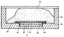
- a hook-and-loop fastener 80 described in Patent Document 1 includes a hook-and-loop fastener member 81 in which a large number of hook-like engagement elements 83 are erected on the surface of a flat plate-like base material 82, A resin intrusion prevention member 84 made of a non-woven fabric having a substantially L-shaped cross section and disposed on the left and right side edges of the base material 82 and a fixing member 85 made of a non-woven fabric arranged on the back surface of the base material 82 are provided. is doing.
- the resin intrusion prevention member 84 and the fixing member 85 are fixed to the hook-and-loop fastener member 81 by welding such as ultrasonic welding or high-frequency welding, or adhesion by an adhesive. Further, the resin intrusion prevention member 84 having a substantially L-shaped cross section is disposed away from the position of the hook-like engagement element 83 erected on the base material 82 in the width direction.
- the surface fastener 80 is formed on the inner surface (cavity surface) of the cushion body molding die 86.
- the foamed resin material 87 is injected into the internal space (cavity) of the mold 86.
- the inner surface of the mold 86 is provided with a groove portion (trench portion) 88 for inserting and positioning the surface fastener 80 by inserting a part of the surface fastener 80. It is formed to have a groove shape, a groove size, and a groove depth corresponding to the form of the fastener 80.
- a large number of engagement elements 83 and one piece of a substantially L-shaped resin intrusion prevention member 84 are inserted into the concave groove 88 of the mold 86. At this time, the other piece of the resin intrusion prevention member 84 is disposed so as to be sandwiched between the base material 82 of the surface fastener 80 and the inner surface of the mold 86.
- the foamed resin material 87 is injected into the mold 86 in a state where the surface fastener 80 is set in the concave groove portion 88 of the mold 86 to perform foam molding, whereby the resin intrusion prevention member 84 made of nonwoven fabric is foamed. It is possible to manufacture the cushion body in which the hook-and-loop fastener 80 is integrated by absorbing the resin material 87 and preventing the foamed resin material 87 from entering the recessed groove portion 88.
- the cushion body in which the hook-and-loop fastener 80 manufactured as described above prevents the engaging element 83 of the hook-and-loop fastener 80 from being filled with the foam, and the engaging element 83 of the hook-and-loop fastener 80 is prevented from being buried. It can be exposed to the outer surface of the cushion body. For this reason, in the cushion body in which the hook-and-loop fastener 80 is integrated, it is possible to prevent the engagement force from being lowered by the engagement element 83.
- Patent Document 2 there is a molded surface fastener in which an anchor layer made of a nonwoven fabric is fixed to the back surface side of a base material on which a plurality of engaging elements are erected. It is disclosed.
- the molded surface fastener of Patent Document 2 is configured such that a nonwoven fabric serving as an anchor layer extends outward in the width direction from the left and right edges of the base material of the molded surface fastener. Further, a magnetically adsorbable coating layer is formed on the back surface side of the portion fixed to the non-woven fabric substrate and on the surface side of the portion extending outward from the left and right side edges of the substrate. Yes.
- a molding die in which a magnet is arranged on the cavity surface is used.
- the coating layer formed on the nonwoven fabric of the molded surface fastener is attracted to the magnet by placing the molded surface fastener on the portion of the mold where the magnet is disposed so that the plurality of engaging elements face the cavity surface. .
- the molded surface fastener is attracted and fixed to the cavity surface of the mold by magnetic force, and the nonwoven fabric extending from the left and right side edges of the base material is attracted to the magnet and is in contact with the cavity surface of the mold It becomes.
- the nonwoven fabric extending from the left and right side edges of the base material is in contact with the cavity surface, and a plurality of engagement elements are confined inside the nonwoven fabric.
- the foamed resin material can be prevented from entering the forming area of the engaging element of the molded surface fastener, and a cushion body integrated with the surface fastener can be manufactured.
- the above-described inner surface of the mold 86 is formed on the inner surface of the mold 86 corresponding to the location where the surface fastener 80 of the cushion body is provided.
- Such a concave groove portion (trench portion) 88 is provided in advance, and the surface fastener 80 of Patent Document 1 needs to be positioned and held with respect to the mold 86.
- the shape and size of the cushion body integrated with the hook-and-loop fastener are often changed depending on the application, and the mounting position of the hook-and-loop fastener integrated with the cushion body is also changed.
- the types of foamed resin materials constituting the cushion body differ depending on the manufacturer or the like that manufactures the cushion body.
- the hook-and-loop fastener 80 is provided on the flat surface portion of the inner surface of the mold 86 without providing the concave groove 88 as described above on the inner surface of the mold 86.
- the left and right resin intrusion prevention members 84 made of a plurality of engaging elements 83 and nonwoven fabric are installed so as to face the flat surface, and the foaming of the cushion body is performed.
- foam molding By performing foam molding in this way, a plurality of engagement elements 83 are confined inside the left and right resin intrusion prevention members 84, and therefore, the foamed resin material 87 is formed on the engagement elements 83 of the molded surface fastener 80. It also seems to be able to prevent entry into the formation area.
- the L-shaped resin intrusion prevention member 84 having a L-shaped cross section is made of a nonwoven fabric, and the L-shaped piece of the nonwoven fabric is erected from the base material 82 alone. Is retained.
- the resin intrusion prevention member 84 composed of the nonwoven fabric standing up alone from the base material 82 does not provide sufficient strength as a barrier (barrier) to prevent the intrusion of the foamed resin material.
- one piece of the prevention member 84 may easily fall over or bend.
- the resin intrusion prevention member 84 in Patent Document 1 cannot sufficiently withstand the flow pressure and foaming pressure of the foamed resin material 87 injected into the mold 86 at the time of foam molding, and as a result, it has collapsed or
- the bent resin intrusion preventing member 84 allows the foamed resin material 87 to enter the portion where the plurality of engaging elements 83 are erected, which may reduce the engaging force of the molded surface fastener 80. .
- the molded surface fastener of Patent Document 2 uses the magnetic force between the coating layer of the nonwoven fabric and the magnet, the nonwoven fabric extension piece that prevents the foamed resin material from entering the engaging element forming region is provided. Easy to move. For this reason, when the flow pressure or foaming pressure of the foamed resin material injected into the mold increases, the extending piece that has been in contact with the cavity surface of the mold becomes the flow pressure or foaming of the foamed resin material. There was a possibility of floating from the cavity surface under pressure, which could allow the infiltration of the foamed resin material.
- the extending piece of the non-woven fabric extending from the base material just like the molded surface fastener of Patent Document 2 is in contact with the cavity surface of the mold. There is a possibility that the infiltration of the foamed resin material cannot be sufficiently prevented.
- a foamed resin material may be sprayed from the spray nozzle while moving the spray nozzle relative to the mold.
- the foamed resin material may be sprayed from the oblique direction with respect to the molded surface fastener.
- the foamed resin material is obliquely applied to the molded surface fastener of Patent Document 2 set on the cavity surface of the mold.
- the non-woven fabric extension piece extending from the base material and in contact with the cavity surface tends to sag, allowing the foamed resin material to enter from the squeezed part of the extension piece.
- a molded surface fastener provided by the present invention is erected in a central region in the width direction of a flat substrate and a first surface of the substrate as a basic configuration.
- a molded surface fastener having at least one hook-and-loop fastener member having a plurality of engaging elements and integrated with the cushion body during foam molding of the cushion body, the width direction of the first surface of the base material
- a sheet-like resin material intrusion prevention member having flexibility and disposed along the length direction of the base material, and the resin material intrusion prevention member fixed to the base material.
- Left and right support members that support the resin material intrusion prevention member, and are arranged on the inner side in the width direction of the base material, along the length direction of the base material, and an upper end portion of the resin material intrusion prevention member Than the upper end position of the support member. Be protruding towards it is an most important feature.
- the molded surface fastener according to the present invention is constituted by one of the surface fastener members, and the resin material intrusion prevention member is continuously arranged over the entire length direction of the base material. And a second frame portion that is disposed along the width direction of the hook-and-loop fastener member at both ends in the length direction of the hook-and-loop fastener member and connects the left and right first frame portions. It is preferable.
- the first frame portion and the second frame portion are integrally formed, and the resin material intrusion prevention member is constituted by a single member.
- the resin material intrusion prevention member has a rectangular opening surrounded by the first frame portion and the second frame portion, and the dimension in the width direction of the opening is the outer surface of the left and right support members. It is preferable that the dimension in the length direction of the opening is set smaller than the dimension in the length direction of the hook-and-loop fastener member.
- the sheet-shaped resin material intrusion prevention member has a tubular form in which side edges of the resin material intrusion prevention member are connected to each other. It may be fixed to the left and right side edges.
- the molded surface fastener according to the present invention includes a plurality of the surface fastener members and a flexible connection member that connects the plurality of surface fastener members along the length direction, and the resin material.
- the intrusion prevention member spans a plurality of the hook-and-loop fastener members and the left and right first frame portions continuously arranged in the length direction, and the width direction of the hook-and-loop fastener member straddling between the adjacent hook-and-loop fastener members.
- a second frame portion that connects the left and right first frame portions.
- the first frame portion and the second frame portion are integrally formed, and the resin material intrusion prevention member is constituted by a single member.
- the sheet-shaped resin material intrusion prevention member has a certain width dimension over the entire length direction, and covers a plurality of the surface fastener members over the entire width direction of the surface fastener member. It is preferable.
- the connection member is connected to the center portions in the width direction of the plurality of hook-and-loop fastener members on the lower surface side of the resin material intrusion prevention member.
- the molded surface fastener which concerns on this invention WHEREIN It is preferable that the said resin material permeation prevention member is extended in the width direction outer side from the left-right side edge of the said base material. Furthermore, it is preferable that the resin material intrusion prevention member is made of a nonwoven fabric.
- the left and right support members are integrally formed on the base material so as to sandwich an engagement element region formed by a plurality of engagement elements, and are intermittently or continuously raised along the front-rear direction. It is preferable that the wall member is provided.
- the molded surface fastener having the above-described configuration is brought into close contact with the fastener mounting surface of the mold so that the first surface side of the base material faces the surface.
- the most main feature is to produce a cushion body in which the molded surface fastener is integrated by performing foam molding in the above state.
- the manufacturing method of the cushion body which concerns on this invention includes the said fastener mounting surface of the said metal mold
- the molded surface fastener according to the present invention is fixed to at least one surface fastener member in which a plurality of engaging elements are erected in a central region of a flat base material, and right and left side edges of the base material.
- a sheet-shaped resin material intrusion prevention member having flexibility arranged along the length direction, and the length of the base material on the inner side in the width direction than the fixing portion of the resin material intrusion prevention member to the base material And left and right support members erected along the direction.
- the resin material intrusion prevention member is supported by the support member in a state in which the upper end portion protrudes upward from the upper end position of the support member.
- the 1st surface of a base material means the surface of the side by which an engaging element is erected, and is a surface of the side exposed outside when a molded surface fastener is integrated with a cushion body.
- the second surface of the base material refers to a surface opposite to the side on which the engaging element is erected, and when the molded surface fastener is integrated with the cushion body, the second surface of the base material faces the cushion body. Surface.
- the foamed resin material exceeds the resin material intrusion prevention member of the molded surface fastener at the time of foam molding of the cushion body, and in the engagement element region where a plurality of engagement elements are erected. Intrusion can be effectively prevented. For this reason, the molded surface fastener integrated with the cushion body can stably secure the engagement force (engagement force) inherent to the plurality of engagement elements formed on the molded surface fastener.
- the molded surface fastener of the present invention can effectively prevent the foamed resin material from entering the engaging element region, particularly when set on a cavity surface (for example, a flat cavity surface) formed of a single surface of a mold. Therefore, for example, as in Patent Document 1 described above, it is not necessary to provide a dedicated concave groove (trench) in order to position and hold the surface fastener on the inner surface of the mold. For this reason, the cost and work burden associated with the fabrication of the mold for molding the cushion body can be greatly reduced compared to the case of Patent Document 1, and the cushion body integrated with the molded surface fastener can be manufactured at low cost and efficiently. Can be manufactured automatically.
- the resin material intrusion prevention member is disposed on the left and right sides continuously arranged over the entire length direction of the base material. It has a 1st frame part and the 2nd frame part distribute
- the foamed resin material is prevented from entering the resin material from the width direction of the molded surface fastener. Can be prevented from entering the engaging element region, and can be stably prevented from entering the engaging element region beyond the resin material intrusion prevention member from the length direction of the molded surface fastener. For this reason, the molded surface fastener integrated with the cushion body can secure the engagement force (engagement force) inherently more stable.
- the resin material intrusion prevention member is constituted by a single member in which the first frame portion and the second frame portion are integrally formed.
- surface fastener member becomes easy, and the molded surface fastener of this invention can be manufactured efficiently.
- the strength of the resin material intrusion prevention member can be stably secured, and the first frame portion and the second frame portion can penetrate the foamed resin material. Can be more effectively prevented.
- the resin material intrusion prevention member has a rectangular opening surrounded by the first frame part and the second frame part, and the dimension in the width direction of the opening part is larger than the dimension between the outer surfaces of the left and right support members.
- the dimension in the length direction of the opening is smaller than the dimension in the length direction of the hook-and-loop fastener member.
- the resin material intrusion prevention member can more stably prevent the foam resin material from entering the engagement element region, and the molded surface fastener can be formed from the opening of the resin material intrusion prevention member. It is also possible to prevent a part of the engagement element and the support member from protruding (exiting) upward from the resin material intrusion prevention member.
- the sheet-shaped resin material intrusion prevention member has a cylindrical form in which the side edges of the resin material intrusion prevention member are connected to each other on the left and right sides of the base material. It may be fixed to the edge. Also by this, at the time of foam molding of the cushion body, the resin material intrusion preventing member can stably prevent the foamed resin material from entering the engaging element region.
- the molded surface fastener according to the present invention has a plurality of surface fastener members and a flexible connecting member that connects the plurality of surface fastener members along the length direction
- a resin is provided.
- the material intrusion prevention member extends along the width direction of the hook-and-loop fastener member, straddling between the left and right first frame portions continuously arranged in the length direction across the plurality of hook-and-loop fastener members and the adjacent hook-and-loop fastener members. And a second frame portion that connects the left and right first frame portions.
- the resin material intrusion prevention member is By having such a 1st frame part and a 2nd frame part, while ensuring the bendability of a molded surface fastener, at the time of foam molding of a cushion body, a foamed resin material is from the width direction and length direction of a molded surface fastener. It is possible to stably prevent the resin material intrusion prevention member from entering the engaging element region.
- the cushion body when the cushion body is foam-molded, a part of the first frame part and a part of the second frame part of the resin material intrusion prevention member can be embedded in the cushion body, so that the molding surface
- the bonding strength (adhesion strength) between the fastener and the cushion body is increased, and the molded surface fastener can be firmly fixed and integrated with the cushion body.
- the resin material intrusion prevention member is constituted by a single member in which the first frame portion and the second frame portion are integrally formed.
- the sheet-like resin material intrusion prevention member has a length. It has a fixed width dimension over the entire direction, and covers a plurality of hook-and-loop fastener members over the entire width direction of the hook-and-loop fastener member.
- the resin material intrusion prevention member can be easily configured, and the resin material intrusion prevention member can be easily attached to the surface fastener member, so that the molded surface fastener of the present invention can be efficiently manufactured.
- the first frame portion and the second frame portion are integrally formed, the strength of the resin material intrusion prevention member can be stably secured, and the first frame portion and the second frame portion can infiltrate the foamed resin material. Can be more effectively prevented.
- the second frame portion of the resin material intrusion prevention member can be embedded in a large area in the cushion body, so that the bonding strength (fixing strength) between the molded surface fastener and the cushion body is further increased. It is done.
- the connecting member connects the center portions in the width direction of the plurality of hook-and-loop fastener members in the length direction on the lower surface side of the resin material intrusion prevention member.
- the resin material intrusion prevention member when the cushion material is foam-molded by the resin material intrusion prevention member extending outward in the width direction from the left and right side edges of the base material, the resin material An extension portion of the intrusion prevention member is embedded in the cushion body.
- the joint strength adheresion strength
- the molded surface fastener can be firmly fixed and integrated with the cushion body.
- the resin material intrusion prevention member is made of a nonwoven fabric having flexibility. Therefore, the resin material intrusion prevention member as described above can be easily configured, and the high sealing performance of the resin material intrusion prevention member with respect to the cavity surface of the mold can be obtained more stably.
- the left and right support members are constituted by wall members that are erected intermittently or continuously along the front-rear direction so as to sandwich an engagement element region constituted by a plurality of engagement elements.
- the resin material intrusion prevention member can be supported more stably, even if it receives the flow pressure or foaming pressure of the foamed resin material during foam molding of the cushion body, the position of the resin material intrusion prevention member is prevented from shifting, It is possible to more effectively prevent the foamed resin material from entering the engaging element region beyond the resin material intrusion prevention member.
- the wall member erected intermittently or continuously in the front-rear direction is arranged in a plurality of rows in the width direction
- the molded surface fastener can be stably fixed in an appropriate posture.
- the resin material intrusion prevention member can be stably adhered to the cavity surface of the mold.
- the resin material intrusion prevention member is closely attached to the cavity surface such that the resin material ingress prevention member is sandwiched between the support member and the cavity surface of the mold (see Example 1 described later), the resin material intrusion prevention member Can be brought into close contact with the cavity surface in a wider area, and the infiltration of the foamed resin material can be further effectively prevented.
- foam molding is performed in a state in which the molded surface fastener having the above-described configuration is in close contact with the fastener mounting surface of the mold so that the first surface side of the base material is opposed.
- the manufacturing method which manufactures the cushion body with which the said molded surface fastener was integrated is provided. By using such a cushion body manufacturing method, the foamed resin is not infiltrated into the engaging element region of the molded surface fastener, and the cushion with the molded surface fastener ensures a predetermined engaging force by the engaging element.
- the body can be manufactured stably.
- the engaging element female-type engaging element disposed on the back surface of the skin material is integrally molded with the cushion body.
- the mating element male engagement element
- the fastener mounting surface of the mold is constituted by a single surface, and the molded surface fastener as described above is brought into close contact with the single surface, and foam molding of the cushion body is performed. Done.
- the molded surface fastener is brought into close contact with the single-sided fastener mounting surface of the mold, it is possible to prevent the foamed resin from entering the engaging element region of the molded surface fastener. It is possible to stably produce a cushion body with a molded surface fastener provided with
- the inner surface of the mold In order to position and hold the hook-and-loop fastener, it is not necessary to provide a dedicated concave groove (trench). Further, for example, even when the position of the molded surface fastener with respect to the cushion body is changed, it is not necessary to prepare a new mold each time, for example, as in Patent Document 1 described above. Therefore, the cost and work burden associated with the production of the mold for molding the cushion body can be greatly reduced as compared with the case of Patent Document 1, and the cushion body integrated with the molded surface fastener can be efficiently produced at low cost. Can be manufactured.
- FIG. 3 is a sectional view taken along line III-III shown in FIG.
- FIG. 4 is a sectional view taken along line IV-IV shown in FIG. 1.
- FIG. 8 is a sectional view taken along line IX-IX shown in FIG. 7.
- FIG. 8 is a sectional view taken along line XX shown in FIG. 7.
- FIG. 14 is a sectional view taken along line XIV-XIV shown in FIG. 13.
- FIG. 19 is a sectional view taken along line XX-XX shown in FIG.
- FIG. 19 is a sectional view taken along line XXI-XXI shown in FIG.
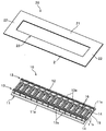
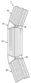
- FIG. 1 is a plan view showing a molded surface fastener according to the first embodiment
- FIG. 2 is a perspective view showing a state before the resin material intrusion prevention member is fixed to the surface fastener member in the molded surface fastener.
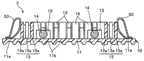
- 3 and 4 are sectional views taken along lines III-III and IV-IV shown in FIG.
- the longitudinal direction in the base material of the molded surface fastener is defined as the front-rear direction
- the width direction in the base material is defined as the left-right direction.
- the front-back direction in a base material is prescribed
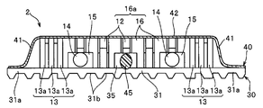
- the molded surface fastener 1 according to the first embodiment is fixed to one surface fastener member 10 in which a plurality of engaging elements 12 are erected on the upper surface (first surface) of a base material 11 and the surface fastener member 10. And a resin material intrusion prevention member 20 having a frame shape.
- the hook-and-loop fastener member 10 includes a flat base material 11, left and right support members 13 erected on the upper surface (first surface) of the base material 11 along the length direction (front-rear direction), and left and right support members.
- a plurality of engagement elements (hook-like male engagement elements) 12 disposed between the two elements 13, two linear magnetic bodies 14 disposed along the front-rear direction, and the inside of the left and right support members 13.
- the surface fastener member 10 is formed by molding a thermoplastic resin material using a die wheel as will be described later.
- thermoplastic resin materials such as polyethylene, a polypropylene, polyester, nylon, polybutylene terephthalate, or those copolymers, are employable.
- the linear fastener 14 is formed, the linear magnetic member 14 is introduced into the portion where the fixing portion 15 of the hook-and-loop fastener member 10 is formed, thereby fixing the fixing portion 15. It is integrally molded so that it may be fixed to.
- the base material 11 in the first embodiment has a thin plate shape that is long in the front-rear direction (length direction) when viewed from the up-down direction, and can be bent in the up-down direction (front-back direction). It is configured.
- the base material 11 is arranged in the central region in the width direction, and is wider than the central region portion where the plurality of engaging elements 12 and the left and right support members 13 are erected, and the erected position of the left and right support members 13.
- And left and right side edge portions 11a disposed on the outer side.
- the upper surface (first surface) of the left and right side edge portions 11a of the substrate 11 is formed as a flat surface.
- the left and right edges of the base material 11 are formed in parallel to each other along the length direction of the hook-and-loop fastener member 10.
- a plurality of concave grooves 11b parallel to the front-rear direction are provided on the lower surface (back surface) side of the base material 11.
- the base 11 has such a plurality of concave grooves 11b, the base of the hook-and-loop fastener member 10 when the molded surface fastener 1 is molded and integrated during foam molding of a cushion body (foam) 6 described later. 11 and the cushion body 6 can be increased in bonding area, and the fixing strength of the hook-and-loop fastener member 10 to the cushion body 6 can be increased.
- a protruding portion or a twisted shape is formed on the lower surface of the base material 11.
- a protrusion or the like may be provided, or a nonwoven fabric may be fixed.
- the left and right support members 13 are positioned inwardly in the width direction (left and right direction) from the left and right side edges of the base material 11 with the engagement element region 18 formed by the plurality of engagement elements 12 interposed therebetween.
- the left and right support members 13 are integrally formed with the base material 11.
- the left and right support members 13 each have three vertical wall rows extending in the length direction, and each vertical wall row is intermittently arranged at a predetermined pitch in the length direction.
- the plurality of vertical wall bodies 13a are configured.
- the support member 13 is provided with a vertical wall connecting portion that connects the vertical wall bodies 13a of the vertical wall rows adjacent in the width direction.
- the support member 13 may be any member that can support the resin material intrusion prevention member 20, but preferably, at least one vertical wall member (vertical wall row) extending intermittently or continuously in the length direction. It is preferable that That is, the support member 13 is arranged in a zigzag manner, for example, one or more vertical wall members standing continuously in the length direction, or a plurality of vertical wall bodies arranged intermittently as described above. It may be a vertical wall member.
- the vertical wall body 13a of the vertical wall row arranged closest to the engaging element 12 of the support member 13 is defined as the first vertical wall body 13a, and the first row of vertical wall bodies 13a is outside the first row vertical wall body 13a.
- the vertical wall body 13a of the arranged vertical wall row is the second vertical wall body 13a, and the vertical wall body 13a of the outermost vertical wall row is the third vertical wall body 13a.
- the structure of the left and right support members 13 is not particularly limited.
- the configuration and the number of vertical wall bodies 13a constituting the support member 13 of the first embodiment (the number of vertical wall rows) ) Can be changed arbitrarily.
- the vertical wall bodies 13a in each row are intermittently arranged with a predetermined mounting pitch in the length direction, and a predetermined gap is provided in the length direction between the vertical wall bodies 13a in each row. Is provided. Also, the vertical wall bodies 13a in the second row are arranged so as to correspond to the positions of the gaps formed between the vertical wall bodies 13a in the first row and the third row. The vertical wall bodies 13a in the third row are arranged in a staggered manner so as to have an alternate positional relationship between the vertical wall rows.
- the connecting portion of the vertical wall body 13a of the support member 13 is disposed between the vertical wall body 13a in the first row and the third row and the vertical wall body 13a in the second row, and the first row. And the front-end part and rear-end part of the vertical wall body 13a of the 3rd row
- the height dimension (vertical dimension) of the connecting portion is set lower than the vertical wall body 13a in the first to third rows, and the width dimension (horizontal dimension) of the connecting portion. Is set to the same size as the interval in the width direction between the vertical wall body 13a in the first and third rows and the vertical wall body 13a in the second row.
- the space provided between the vertical wall bodies 13a in each vertical wall row can be expanded or narrowed.
- 10 molded surface fastener 1
- the resin intrusion prevention member 20 is fixed to the hook-and-loop fastener member 10 so as to cover the upper surface side of the support member 13 as will be described later.
- the resin intrusion prevention member 20 can be widely supported in the width direction on the upper surface side of the support member 13 to stabilize the position of the resin intrusion prevention member.
- the resin material intrusion prevention member 20 when the molded surface fastener 1 is adsorbed and fixed to the cavity surface (fastener mounting surface) 7 a of the mold 7, the resin material intrusion prevention member 20 is connected to the support member 13 and the cavity surface 7 a of the mold 7. Can be sandwiched widely in the width direction. For this reason, the resin material intrusion prevention member 20 can be in wide and stable contact with the upper surface portion of the support member 13 and the resin material intrusion prevention member 20 can be in wide and stable contact with the cavity surface 7 a of the mold 7. As a result, the sealing performance by the resin material intrusion prevention member 20 (that is, the sealing performance between the surface fastener member 10 sandwiching the resin material intrusion prevention member 20 and the cavity surface 7a) can be greatly improved.
- the engaging elements 12 are erected on the upper surface of the base material 11 so as to be aligned with a predetermined mounting pitch in the length direction and the width direction so as to obtain an engaging force with the skin material covered on the cushion body 6. ing. Particularly in the case of the first embodiment, the columns of the engaging elements 12 aligned along the length direction are arranged between the left and right support members 13 in five rows in the width direction.
- the engagement element region 18 in the hook-and-loop fastener member 10 includes left and right support members 13, and a lateral support portion 16a that a lateral wall body 16 disposed on the most front end side together with the engagement element 12 as will be described later.
- a horizontal wall 16 disposed on the most rear end side is formed by a portion surrounded by a horizontal support portion 16 a configured together with the engagement element 12.
- Each engaging element 12 has a rising portion that rises vertically from the upper surface of the base material 11 and a hook-shaped engaging head that branches and curves in the front-rear direction at the upper end of the rising portion. Furthermore, the height dimension (vertical dimension) of each engagement element 12 from the upper surface of the base material 11 is set to the same size as the height dimension of the support member 13 (height dimension of the vertical wall body 13a). ing. In the present invention, the shape, dimensions, mounting pitch, and the like of the engagement element 12 are not particularly limited and can be arbitrarily changed.
- the horizontal wall 16 is erected along the width direction between the support member 13 and the engagement element 12 and between the engagement elements 12 adjacent to each other in the width direction.
- the horizontal wall body 16 is connected to the engaging element 12 arranged adjacent to each other at the lower end (end on the base material 11 side) (see FIGS. 3 and 4).
- the horizontal wall body 16 and the engaging element 12 are reinforced together.
- the lateral wall 16 and the engaging element 12 may be formed apart from each other.
- the plurality of horizontal wall bodies 16 arranged along the width direction on the most front end side and the rear end side of the hook-and-loop fastener member 10 together with the engagement elements 12 arranged so as to be sandwiched between these horizontal wall bodies 16 are made of resin.
- a lateral support portion 16a that supports the back side of a lateral frame portion (second frame portion) 22 to be described later of the material intrusion prevention member 20 along the width direction is configured.
- the height dimension from the upper surface of the base material 11 in each horizontal wall body 16 is set to the same size as the vertical dimension of the vertical wall body 13a and the engagement element 12. That is, in the first embodiment, the upper ends of the vertical wall body 13a, the horizontal wall body 16, and the engagement element 12 are arranged on the same plane. Therefore, as will be described later, the vertical frame portion (first frame portion) 21 and the horizontal frame portion (second frame portion) 22 of the resin material intrusion prevention member 20 are placed on the upper end surface of the support member 13 and the horizontal support portion 16a. When placed on the end face, the height positions of the parts on which the resin material intrusion prevention member 20 is placed can be matched (aligned) with each other.
- the linear magnetic body 14 is arranged on the upper surface side of the base material 11 along the row of the engagement elements 12 arranged closest to the left and right support members 13 in the engagement element region 18 of the hook-and-loop fastener member 10. It is fixed via the fixed part 15 arranged.
- the linear magnetic body 14 has a circular cross section and is made of a magnetically attracted material or a magnetically attracted material.
- a cushion is used by using a mold 7 in which a magnet 8 is disposed on the cavity surface 7 a or in the vicinity of the cavity surface 7 a.
- the molded surface fastener 1 is made to be the cavity surface 7a of the mold 7 by utilizing the magnetic force generated between the magnet 8 of the mold 7 and the linear magnetic body 14 of the molded surface fastener 1. Can be stably adsorbed and fixed.
- the linear magnetic body 14 As a material of the linear magnetic body 14 that is magnetically attracted, a monofilament in which magnetic particles made of an alloy such as iron, cobalt, nickel, etc. are mixed into a synthetic resin such as polyester, or a metal thin wire made of these alloys is used. Several twisted bundles of metal can be used.
- the magnetically attracting linear magnetic body 14 may be a magnetized wire, specifically a metal linear magnet or a linear rubber magnet magnetized by containing magnetic iron oxide in rubber. Can be used. In the present invention, a thin tape-like magnetic body can be used instead of the linear magnetic body.
- the fixing portion 15 that fixes the linear magnetic body 14 to the base material 11 is disposed at a position in the vicinity of the inside of the support member 13 at a predetermined interval along the length direction. Has a shape protruding in a block shape having a rectangular shape.
- the linear magnetic body 14 is embedded in the fixed portion 15 so as to penetrate the fixed portion 15 in the length direction.
- each fixing portion 15 is configured integrally with the engaging element 12 and the lateral wall body 16 erected from the base material 11.
- the fixing portion 15 may be disposed on the lower surface side of the base material 11 and the linear magnetic body 14 may be fixed on the lower surface side of the base material 11. Further, instead of fixing the linear magnetic body 14 to the base material 11, the surface fastener member 10 may be magnetized by mixing or kneading magnetic particles in the synthetic resin constituting the surface fastener member 10. Is possible.
- the resin material intrusion prevention member 20 fixed to the hook-and-loop fastener member 10 is composed of a thin piece-like sheet member having flexibility.
- the resin material intrusion prevention member 20 of the first embodiment is The non-woven fabric is provided with a predetermined thickness. Since the resin material intrusion prevention member 20 is made of a nonwoven fabric, the resin material intrusion prevention member 20 can be given appropriate flexibility, flexibility, and swelling.
- the material of the resin material intrusion prevention member 20 is not limited.
- the resin material intrusion prevention member 20 can be formed of a woven or knitted thin cloth piece. is there.
- the resin material intrusion prevention member 20 is configured by a single sheet-like member having a frame shape (frame shape). That is, the resin material intrusion prevention member 20 includes left and right vertical frame portions (first frame portions) 21 arranged along the length direction of the molded surface fastener 1, and the front end side and the rear end portion of the surface fastener member 10. It has a horizontal frame portion (second frame portion) 22 that is arranged along the width direction corresponding to the position on the side and connects the left and right vertical frame portions 21, and these left and right A rectangular opening 23 is formed in the central portion of the resin material intrusion prevention member 20 surrounded by the vertical frame portion 21 and the front and rear horizontal frame portions 22.
- first frame portions first frame portions
- second frame portion 22 horizontal frame portion 22 that is arranged along the width direction corresponding to the position on the side and connects the left and right vertical frame portions 21, and these left and right
- a rectangular opening 23 is formed in the central portion of the resin material intrusion prevention member 20 surrounded by the vertical frame portion 21 and the front and rear horizontal frame portions 22
- Such a frame-shaped resin material intrusion prevention member 20 supports the inner peripheral edges (peripheries of the opening 23) of the left and right vertical frame portions 21 and the front and rear horizontal frame portions 22 in the resin material intrusion prevention member 20.
- the hook-and-loop fastener member 10 is bonded or welded to the left and right side edge portions 11a of the base material 11 of the hook-and-loop fastener member 10 with the back surfaces of the left and right vertical frame portions 21 being protruded upward from the upper end position of the member 13. It is fixed to.
- the resin material intrusion prevention member 20 covers a part of the left and right vertical frame portions 21 on the upper surface side of the support member 13 and a part of the front and rear horizontal frame portions 22 to the hook-and-loop fastener member 10. Is fixed to the hook-and-loop fastener member 10 so as to cover the upper surface side of the lateral support portion 16a disposed on the most front end side and the most rear end side.
- the vertical frame portion 21 is foamed when the cushion body 6 is foam-molded as described later. Even if it receives the flow pressure or foaming pressure of the resin material, it is difficult to fall down or bend. Further, it is possible to stably maintain a state in which the inner peripheral edge portion of the vertical frame portion 21 protrudes upward from the upper end position of the support member 13.
- the length dimension of the resin material intrusion prevention member 20 (that is, the vertical dimension of the vertical frame portion 21) is flat before the resin material intrusion prevention member 20 is attached to the hook-and-loop fastener member 10. At this time, it is set to be larger than the length dimension of the base material 11 of the hook-and-loop fastener member 10.
- the length dimension of the base material 11 of the hook-and-loop fastener member 10 is larger. Is also set larger.
- the width dimension of the resin material intrusion prevention member 20 (the dimension in the width direction between the outer edges of the left and right vertical frame portions 21) is flat before the resin material intrusion prevention member 20 is attached to the hook-and-loop fastener member 10. Sometimes, it is set larger than the width dimension of the base material 11 of the hook-and-loop fastener member 10. In particular, in the case of Example 1, even when the resin material intrusion prevention member 20 is fixed to the surface fastener member 10 and partially bent, the width of the base material 11 of the surface fastener member 10 is larger than that of the surface fastener member 10. It is set large.
- the rectangular opening 23 formed in the central portion of the resin material intrusion prevention member 20 has a length dimension smaller than the length dimension of the base material 11 in the hook-and-loop fastener member 10, and the outside of the left and right support members 13.
- the width dimension is smaller than the dimension in the width direction between the wall surfaces (that is, the dimension in the width direction between the left outer wall surface of the left support member 13 and the left outer wall surface of the right support member 13).
- the opening 23 of the resin material intrusion prevention member 20 is set to such a size, the relative position of the opening 23 in the resin material intrusion prevention member 20 with respect to the engaging element region 18 of the hook-and-loop fastener member 10. Can be made difficult to shift. Further, since the position of the opening 23 is difficult to shift, for example, it is possible to prevent a part of the engaging element 12 or the support member 13 from protruding (exiting) from the opening 23 above the resin material intrusion prevention member 20. As a result, the adhesion of the resin material intrusion prevention member 20 to the cavity surface 7a of the mold 7 can be enhanced during foam molding of the cushion body 6.
- the surface fastener member 10 in the molded surface fastener 1 of the first embodiment having the above-described configuration is manufactured using, for example, the following manufacturing apparatus.
- the surface fastener member 10 manufacturing apparatus is omitted in the drawing, but a die wheel that is driven and rotated in one direction, and a continuous extrusion nozzle of a molten resin disposed to face the peripheral surface of the die wheel.
- a pickup roll disposed on the downstream side in the rotational direction of the die wheel from the continuous extrusion nozzle so as to face the peripheral surface of the die wheel, and disposed on the upstream side in the rotational direction of the die wheel from the continuous extrusion nozzle.
- Cutting that cuts the linear magnetic body 14 that introduces the linear magnetic body 14 between the opposed surfaces of the continuous extrusion nozzle and the long hook-and-loop fastener member 10 peeled off from the peripheral surface of the die wheel to a predetermined length.
- Forming cavities for forming the engaging element 12, the left and right support members 13, the lateral wall body 16, and the like of the hook-and-loop fastener member 10 are formed on the peripheral surface of the die wheel included in the manufacturing apparatus.
- circulates a cooling fluid inside the die wheel, and the cooling fluid tank is distribute
- the molten resin material is continuously extruded from the continuous extrusion nozzle toward the peripheral surface of the die wheel.
- the die wheel is driven and rotated in one direction, and the molten resin extruded on the peripheral surface forms the base 11 of the surface fastener member 10 between the continuous extrusion nozzle and the die wheel,
- the engaging element 12, the left and right support members 13, the lateral wall body 16 and the like are sequentially formed in the above-described forming cavity.
- the linear magnetic body 14 is supplied from the supply portion to the extrusion position of the molten resin and is integrally formed with the long surface fastener member 10.
- the elongated hook-and-loop fastener member 10 formed on the peripheral surface of the die wheel is solidified by being supported by the peripheral surface of the die wheel and being rotated halfway while being cooled, and then picked up from the peripheral surface of the die wheel by a pickup roll. It is continuously peeled off.
- the long hook-and-loop fastener member 10 (in other words, the long body of the hook-and-loop fastener member 10) peeled off from the die wheel is conveyed toward the cutting portion, and the cutting portion has a predetermined length. Disconnect. Thereby, the hook-and-loop fastener member 10 of a predetermined length as shown in FIG. 2 is manufactured.
- surface fastener member 10 are not specifically limited, It can change arbitrarily.
- the frame-shaped resin material intrusion prevention member 20 is covered from the upper surface side to the surface fastener member 10 of the first embodiment manufactured as described above, and the left and right sides of the base material 11 in the surface fastener member 10.
- the molded surface fastener 1 of the present Example 1 as shown in FIG. 1 is manufactured.
- the resin material intrusion prevention member 20 faces the resin material intrusion prevention member 20 so that the position of the opening 23 of the resin material intrusion prevention member 20 matches the position of the engaging element region 18 of the surface fastener member 10.
- 10 By covering the upper surface side of the fastener member 10 and further fixing the lower surfaces (rear surfaces) of the left and right vertical frame portions 21 of the resin material intrusion prevention member 20 to the upper surfaces of the left and right side edge portions 11a of the base material 11, 10 is attached.
- adhesion by an adhesive welding by high frequency welding, thermal welding, or the like can be used. .
- the molded surface fastener 1 according to the first embodiment manufactured using the method as described above is formed on a cushion body 6 at the same time that a cushion body (foam body) 6 such as a seat for an automobile is foamed. It is integrated by molding (two-color molding).
- the manufactured molded surface fastener 1 is placed on a fastener placement surface formed at a predetermined position on the cavity surface 7a of the cushion body molding die 7 as shown in FIG. To do.
- the fastener mounting surface on which the molded surface fastener 1 is mounted (set) is configured by a flat surface that is a single surface.
- the fastener mounting surface may be configured by a curved surface that is a convex or concave single surface.
- a magnet 8 such as a neodymium magnet is embedded in the mold 7 corresponding to the position of the fastener placement surface on which the molded surface fastener 1 is placed.
- the magnet 8 is mounted by placing the molded surface fastener 1 in such a direction that the surface (upper surface) of the base member 11 on which the engagement element 12 is formed faces the fastener placement surface of the mold 7.
- the linear magnetic body 14 disposed on the molded surface fastener 1 is attracted by the attraction force, and the molded surface fastener 1 is attracted and fixed to the flat cavity surface (fastener placement surface) 7 a of the mold 7.
- the molded surface fastener 1 of the first embodiment includes a part of the resin material intrusion prevention member 20, in particular, the upper surfaces of the left and right support members 13 of the surface fastener member 10 in the resin material intrusion prevention member 20, the lateral wall body 16, and A portion placed on the upper surface of the lateral support portion 16 a formed by the engagement element 12 is held in a state of being in close contact with the flat cavity surface (fastener placement surface) 7 a of the mold 7.
- the fastener mounting surface of the mold 7 is formed in a concave groove shape, and the engaging element 12 and the support member of the molded surface fastener 1 are inserted into the concave groove.
- the molded surface fastener 1 can be fixed by suction.
- the part fixed to the left and right side edges of the base material 1 in the resin material intrusion prevention member 20 can be brought into close contact with the cavity surface of the mold 7.
- the molded surface fastener 1 of Example 1 is sucked and fixed to a predetermined position (fastener placement surface) of the cavity surface 7a of the mold 7 and then foamed into the mold 7 from an injection nozzle (not shown).
- the functional resin material is injected and injected.
- the foamed resin material can be injected to every corner of the cavity space of the mold 7 by ejecting the foamed resin material while moving the spray nozzle relative to the mold 7.
- the mold 7 is clamped after a predetermined amount of foamed resin material is sprayed from the spray nozzle. Thereby, the foamed resin material is spread over the entire cavity space of the mold 7 while foaming, and the cushion body 6 is molded.
- the molded surface fastener 1 is positioned and fixed at a predetermined position by the attraction action of the magnet 8 embedded in the mold 7, the position of the molded surface fastener 1 is changed by the flow pressure or foaming pressure of the foamed resin material. It will not be moved.
- the resin material intrusion prevention member 20 of the molded surface fastener 1 of the first embodiment has an upper end projecting upward from the upper end position of the support member 13 and the cavity surface 7 a of the mold 7. Between the engagement element region 18 formed on the hook-and-loop fastener member 10 in the front-rear and left-right directions, and the resin material intrusion prevention member. No gap is formed between the surface fastener member 10 via the cavity 20 and the cavity surface 7a so as to allow the foamed resin material to pass therethrough.
- the resin material intrusion prevention member 20 is arranged between the support member 13 and the cavity surface 7a of the mold 7 because the three vertical wall rows are wide in the width direction. Therefore, it is possible to secure a high sealing property between the surface fastener member 10 and the cavity surface 7a with the resin material intrusion prevention member 20 interposed therebetween.
- the resin material intrusion prevention member 20 since the resin material intrusion prevention member 20 is fixed to the hook-and-loop fastener member 10 with the left and right vertical frame portions 21 supported by the left and right support members 13, the resin material intrusion prevention member 20 receives the flow pressure and foam pressure of the foam resin material.
- the position of the resin material intrusion prevention member 20 can be prevented from shifting, and the state in which the resin material intrusion prevention member 20 is in close contact with the cavity surface 7a of the mold 7 can be stably maintained.
- the engaging element region 18 of the molded surface fastener 1 that is attracted and fixed to the cavity surface 7a of the mold 7 is stabilized from the outer region (that is, the cavity space) of the molded surface fastener 1 by the resin material intrusion prevention member 20. Can be blocked.
- Example 1 since the resin material intrusion prevention member 20 is made of a nonwoven fabric that is flexible and has an appropriate swelling feeling, the mold surface fastener 1 is attracted and fixed by the magnet 8, thereby the mold 7. Even if there are minute irregularities on the cavity surface 7a, the resin material intrusion prevention member 20 is firmly attached to the cavity surface 7a of the mold 7 so that there is a gap between the resin material intrusion prevention member 20 and the cavity surface 7a. Can be prevented from being formed.
- the foamed resin material collides with the molded surface fastener 1 vigorously when the foamed resin material is ejected from an injection nozzle (not shown), or when the flow pressure or foaming pressure of the foamed resin material is large, Even when the material has a low viscosity, the foamed resin material passes between the resin material intrusion prevention member 20 and the cavity surface 7a of the mold 7 and enters the engaging element region 18 of the molded surface fastener 1. Can be effectively prevented.
- the engagement element 12 is not filled with the foam in the engagement element region 18 of the molded surface fastener 1, and the engagement element 12 can be stably exposed on the upper surface side of the base material 11. . For this reason, even after foam molding of the cushion body 6, the predetermined engagement force (engagement force) that the molded surface fastener 1 itself has can be stably maintained.
- the left and right side edge portions 11a of the base material 11 are formed on the left and right outer sides of the support member 13, and the resin material intrusion prevention member 20 is provided on the left and right sides of the base material 11.
- the left and right first extending portions 24 extending outward from the side edge and the front and rear second extending portions 25 extending outward from the front and rear end edges of the base 11 are provided.
- the foamed resin material when the foamed resin material is sprayed from the spray nozzle, the left and right extending portions of the base material 11 and the first and second extending portions 24 and 25 of the resin material intrusion preventing member 20 are Therefore, the injected foamed resin material can be prevented from striking directly between the resin material intrusion prevention member 20 and the cavity surface 7a, and the foamed resin material can be prevented from entering the engaging element region 18. It can be prevented more effectively.
- the foamed resin material is foamed and solidified in the cavity space of the mold 7 and the molding is completed.
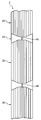
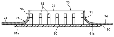
- the cushion body 6 in which the molded surface fastener 1 of the first embodiment is integrated as shown in FIG. Can be obtained.
- the surface of the obtained cushion body 6 is covered with a non-illustrated skin material, and the skin material is pressed toward the mounting position of the molded surface fastener 1 in the cushion body 6 to be arranged on the back surface of the skin material.
- the female engaging element 12 can be reliably engaged with the engaging element 12 (male engaging element) of the molded surface fastener 1. Accordingly, the skin material can be accurately attached along the surface of the cushion body 6 without being lifted from the cushion body 6.
- the cushion body 6 can be foam-molded by adsorbing and fixing to the flat cavity surface 7a of the mold 7 as described above.
- the cost and work burden related to the production of the mold 7 for molding the cushion body 6 can be greatly reduced as compared with the case of Patent Document 1, and the cushion body 6 with the molded surface fastener 1 can be manufactured at low cost. It can be manufactured efficiently.
- the foamed resin is infiltrated into a part of the resin material intrusion prevention member 20 made of a nonwoven fabric.
- the 1st and 2nd extension parts 24 and 25 extended to the front and rear, right and left from the base material 11 of the resin material intrusion prevention member 20 in the molded surface fastener 1 are inside the cushion body 6 as shown in FIG. Buried.
- the joint strength (adhesion strength) between the molded surface fastener 1 and the cushion body 6 can be effectively increased, and the molded surface fastener 1 can be more firmly integrated with the cushion body 6.
- the resin material intrusion prevention member 20 into which the foamed resin has penetrated has semi-rigidity and can be bent together with the cushion body 6.
- the molded surface fastener of Example 1 having an arbitrary length is prepared by preparing a resin material intrusion prevention member 20 having an opening 23 matched to the length of the surface fastener member 10 and fixing it to the surface fastener member 10. 1 can be easily manufactured.
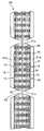
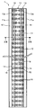
- FIG. 7 is a plan view showing a molded surface fastener according to the second embodiment
- FIG. 8 is a plan view showing a surface fastener member of the molded surface fastener.
- 9 and 10 are sectional views taken along lines IX-IX and XX shown in FIG.
- Example 2 In the following Example 2 and molded surface fasteners 2 to 5 according to Examples 3 to 5 to be described later, the configuration different from the molded surface fastener 1 according to Example 1 will be mainly described.
- the parts and members having substantially the same configuration as the molded surface fastener 1 according to Example 1 described above are denoted by the same reference numerals, and the description thereof is omitted.
- the molded surface fastener 2 includes a plurality of surface fastener members 30 in which a plurality of engaging elements 12 are erected on the upper surface (first surface) of a flat substrate 31 and adjacent surface fastener members. It has the monofilament 45 used as the connection member which connects 30 members in the front-back direction, and the resin material penetration
- FIG. 45 used as the connection member which connects 30 members in the front-back direction, and the resin material penetration
- Each hook-and-loop fastener member 30 includes a base material 31 having a substantially octagonal shape that is long in the length direction (front-rear direction) in a front view, and an upper surface (first surface) of the base material 31 in the length direction.
- a fixing portion (first fixing portion) 15 that is arranged inside the support member 13 and fixes the linear magnetic body 14, a fixing portion (second fixing portion) 35 that fixes the monofilament 45 that is a connection member, and the width direction
- a horizontal wall body 16 arranged along the line.
- each of the engagement elements 12, the left and right support members 13, the linear magnetic body 14, the fixing portion (first fixing portion) 15 that fixes the linear magnetic body 14, and the lateral wall body 16 are each provided. Is configured in the same manner as in the first embodiment. Further, the resin material intrusion prevention member 40 will be described later by a plurality of engagement elements 12 and a plurality of lateral wall bodies 16 arranged along the width direction at the positions of the front end side and the rear end side of each surface fastener member 20. A lateral support portion 16a for supporting the back side of the lateral frame portion (second frame portion) 42 along the width direction is configured.
- the base material 31 in Example 2 is formed in a thin plate shape so that it can be bent in the vertical direction. Moreover, the base material 31 of each hook-and-loop fastener member 30 is disposed in the central region in the width direction, and includes a central region portion where the plurality of engaging elements 12 and the left and right support members 13 are erected, and the left and right support members 13. And left and right side edge portions 31a disposed on the outer side in the width direction from the standing position.
- the upper surface (first surface) of the left and right side edge portions 31 a of the base material 31 is formed as a flat surface, and the left and right side edges of the base material 31 are parallel to each other along the length direction of the hook-and-loop fastener member 30. Is formed. Furthermore, on the lower surface (back surface) side of the base material 31, a plurality of concave groove portions 31b parallel to the front-rear direction are provided.
- the base material 31 has front and rear extending portions 31c which are arranged on the front and rear end edges of the hook-and-loop fastener member 30 and from which the engaging elements 12 are excluded, and these front and rear extending portions 31c. Is formed so as to extend forward and rearward from the arrangement positions of the engaging element 12 and the lateral wall body 16 between the left and right support members 13.
- the left and right side edge portions 31a and the front and rear extension portions 31c as described above are arranged on the base material 31 of each hook-and-loop fastener member 30, so that these left and right side edge portions 31a and the front and rear extension portions are provided.
- 31c serves as a trap for the foamed resin material injected from the injection nozzle during foam molding of the cushion body, and the injected foamed resin material is directly between the resin material intrusion prevention member 40 and the cavity surface 7a. Can be prevented from hitting.
- the engaging element region 38 of the hook-and-loop fastener member 30 is formed by a portion in which a plurality of engaging elements 12 are erected and arranged at a predetermined mounting pitch in the length direction and the width direction. Are arranged so as to extend in the front-rear direction at a position entering the inner side in the width direction (left-right direction) with respect to the left and right side edges of the base material 31 with the engaging element region 38 interposed therebetween.
- the left and right support members 13 in the second embodiment each have three vertical wall rows, as in the first embodiment, and each vertical wall row has a predetermined pitch in the length direction. It is comprised by the some vertical wall body 13a arranged.
- the support member 13 is provided with a vertical wall connecting portion that connects the vertical wall bodies 13a of the vertical wall rows adjacent in the width direction.
- each hook-and-loop fastener member 30 of the second embodiment has a configuration in which the second fixing portion 35 for fixing the monofilament 45 protrudes from the upper surface of the base material 31 into a block shape having a rectangular cross section. Is provided.
- the second fixing portions 35 are arranged at predetermined intervals along the length direction at a substantially central portion in the width direction of the base material 31.
- the second fixing portion 35 is integrally formed with the engaging element 12 and the lateral wall body 16 erected from the base material 31 and reinforces the engaging element 12 and the lateral wall body 16.
- the monofilament 45 is embedded in the second fixing portion 35 so as to penetrate the second fixing portion 35 in the length direction.
- the second fixing portion 35 for fixing the monofilament 45 may be configured separately from the lateral wall body 16.
- the second fixing portion 35 may be disposed on the lower surface side of the base material 31 and the monofilament 45 may be fixed on the lower surface side of the base material 31.
- the monofilament 45 is fixed by the block-shaped second fixing portion 35 disposed on each surface fastener member 30, and the first disposed on the foremost side of each surface fastener member 30.
- Adjacent hook-and-loop fastener members 30 are connected to each other by a portion of a monofilament 45 sandwiched between the fixing portion 35 and the second fixing portion 35 arranged at the rearmost side of the hook-and-loop fastener member 30 adjacent to the front side.
- the connecting part is configured.
- the connecting portion formed of the monofilament 45 is fixed to the second fixing portion 35 disposed at the substantially central portion in the width direction on the lower surface (back surface) side of the resin material intrusion prevention member 40 and is adjacent to the surface fastener.
- Central portions of the members 30 in the width direction are connected to each other.
- the monofilament 45 in the second embodiment is made of a thermoplastic resin such as polyester and has flexibility. Further, the monofilament 45 is configured to be bent in a zigzag shape in the left-right direction, and in particular, at least two bent portions having different bending directions are arranged between the second fixing portions 35 constituting the connection portion. In this way, the folding interval is set. Further, the cross section of the monofilament 45 has an elliptical shape extending long in the front and back direction of the base 31 part so that the major axis is along the vertical direction.
- connection part of the second embodiment is configured as described above, the molded surface fastener 2 having the plurality of surface fastener members 30 can be easily bent in the width direction at the connection part. It is also possible to bend in the front and back direction (see FIG. 12).
- the thickness and the cross-sectional shape of the monofilament 45 are not particularly limited, and may be designed so that the molded surface fastener 2 can be bent at least in the width direction at the connecting portion.
- the connecting member does not need to be composed of the monofilament 45 as in the second embodiment.
- the connecting member is integrally formed with the hook-and-loop fastener member 30 using the same material (same synthetic resin) as the base material 31. A plurality of hook-and-loop fastener members 30 may be connected to each other by the connected members.
- the resin material intrusion prevention member 40 of Example 2 is composed of a single sheet member made of a thin piece of nonwoven fabric having flexibility. Further, the resin material intrusion prevention member 40 straddles between the left and right vertical frame portions (first frame portions) 41 arranged continuously over the plurality of hook-and-loop fastener members 30 and the adjacent hook-and-loop fastener members 30. It has a horizontal frame portion (second frame portion) 42 that is arranged along the width direction and connects the left and right vertical frame portions 41, and the width dimension of the resin material intrusion prevention member 40 itself is:
- the resin material intrusion prevention member 40 is set to have a constant size over the entire length direction.
- the resin material intrusion prevention member 40 is formed with rectangular openings 43 surrounded by the vertical frame portion 41 and the horizontal frame portion 42 at predetermined intervals in the length direction.
- the resin material intrusion prevention member 40 of the second embodiment having such a configuration covers a part of the left and right vertical frame parts 41 on the upper surface side of the support member 13 and a part of the horizontal frame part 42 on each surface.
- the left and right vertical frame portions 41 are provided on the left and right side edge portions of the base material 31 of each surface fastener member 30 so as to cover the upper surface side of the lateral support portion 16 a disposed on the most front end side and the rearmost end side of the fastener member 10. It is fixed to 31a by adhesion or welding.
- the width dimension of the resin material intrusion prevention member 40 (the dimension between the outer edges of the left and right vertical frame portions 41) is determined after the resin material intrusion prevention member 40 is fixed to the surface fastener member 30 and partially bent. In this state, each hook-and-loop fastener member 30 is set to a size that does not protrude (extend) from the left and right edges of the base material 31.
- the sheet-shaped resin material intrusion prevention member 40 is fixed to the surface fastener member 30 and the resin material intrusion prevention member on the surface fastener member 30 between the plurality of surface fastener members 30. It is comprised so that it may become the same dimension as the width dimension of 40 (refer FIG. 11), and the whole width direction of the hook_and_loop
- the bonding strength (adhesion strength) between the molded surface fastener 2 and the cushion body can be more effectively increased.
- each rectangular opening 43 formed in the resin material intrusion prevention member 40 has a length dimension smaller than the length dimension of the base material 31 in each hook-and-loop fastener member 30, and the left and right sides of each hook-and-loop fastener member 30.
- the width dimension is smaller than the dimension in the width direction between the outer surfaces of the support member 13.
- the opening 43 of the resin material intrusion prevention member 40 is set to such a size, the relative position of the opening 43 relative to the engaging element region 38 of each hook-and-loop fastener member 30 is difficult to shift. In addition, it is possible to prevent the engaging element 12 and a part of the support member 13 from protruding upward from the opening 43 beyond the resin material intrusion prevention member 40.
- the molded surface fastener 2 of the second embodiment having the above-described configuration can be easily bent so as to bend or meander in the left-right direction and the front-back direction (see FIG. 12).
- the resin material intrusion prevention member 40 is composed of a non-woven fabric having flexibility, and therefore, between the surface fastener members 30 of the resin material intrusion prevention member 40.
- the part straddling the part the part arranged on the outer peripheral side is stretched (stretched) by the front and rear hook-and-loop fastener members 30, and at the same time the part arranged on the inner peripheral side bends so as to wave It becomes the state.
- the molded surface fastener 2 of the second embodiment is formed in a cushion body (foam body) 6 such as a seat for an automobile by foam molding at the same time as in the case of the first embodiment.
- a cushion body with the molded surface fastener 2 can be obtained.
- the cushion body in which the molded surface fastener 2 of the second embodiment is integrated can prevent the foam from entering the engaging element region 38 of the molded surface fastener 2 as in the case of the first embodiment. Therefore, a desired engaging force can be stably secured by the plurality of engaging elements 12 exposed on the upper surface side of the base material 11. Moreover, the cost and work burden associated with the production of the mold 7 for molding the cushion body can be reduced as compared with the conventional case.
- the molded surface fastener 2 of the second embodiment can be easily bent in the left-right direction as described above, the cavity surface 7a of the mold 7 with the molded surface fastener 2 curved or meandered. Can be adhered to. For this reason, the molding surface fastener 2 of the present Example 2 can be easily made compatible with various forms of cushion bodies.
- the portion disposed on the outer peripheral side of the resin material intrusion prevention member 40 during foam molding is as described above.
- the molded surface fastener 2 is brought into close contact with the cavity surface 7 a of the mold 7 in a state where the portion arranged on the inner peripheral side is bent and has a margin while being stretched (stretched).
- a gap is easily formed between the bent portion arranged on the inner peripheral side of the resin material intrusion prevention member 40 and the cavity surface 7a of the mold 7, and the foamable resin material enters the resin material from the gap. It will be in the state which is easy to enter between the blocking member 40 and the cavity surface 7a.
- the foamable resin material By injecting the foamable resin material into the mold 7 in this state, it is possible to cause the foamable resin material to wrap around the back side of the foamable resin material between the adjacent surface fastener members 30 to be foamed. Become. Thereby, the cushion body which has a predetermined shape can be manufactured stably.
- the connecting portion made of the monofilament 45 but also the protruding portion on the outer peripheral side and the bent portion on the inner peripheral side disposed between the surface fastener members 30 of the resin material intrusion prevention member 40 are provided. Since it can be embedded in the molded cushion body, the bonding strength (adhesion strength) between the molded surface fastener 2 and the cushion body can be increased more effectively.
- the sheet-shaped resin material intrusion prevention member 40 covers the entire area in the width direction between the hook-and-loop fastener members 30 as described above. Thereby, since the resin material intrusion prevention member 40 is embedded in the cushion body in a large area between the surface fastener members 30, the bonding strength (adhesion strength) between the molded surface fastener 2 and the cushion body is further increased. Enhanced.
- FIG. 13 is a plan view showing the molded surface fastener according to the third embodiment
- FIG. 14 is a cross-sectional view taken along the line XIV-XIV shown in FIG.
- the molded surface fastener 3 according to the third embodiment includes one surface fastener member 10 in which a plurality of engagement elements 12 are erected on the upper surface of the base material 11 and left and right independent fasteners fixed to the surface fastener member 10. And a resin material intrusion prevention member 50.
- the hook-and-loop fastener member 10 in the third embodiment is configured in the same manner as the hook-and-loop fastener member 10 in the first embodiment.
- the resin material intrusion prevention member 50 according to the third embodiment is independently fixed to the left and right side edge portions 11a of the base material 11 in the hook-and-loop fastener member 10.
- These left and right resin material intrusion prevention members 50 are constituted by sheet members made of thin thin piece nonwoven fabric having flexibility, and the side edge portions of the sheet members are joined to each other to form a thin piece sheet. It has the form which rounded the member into the cylinder shape.
- the nonwoven fabric constituting the resin material intrusion prevention member 50 has moderate flexibility, flexibility, and swelling.
- the resin material intrusion prevention member 50 formed in a cylindrical shape has the same length as the length of the base material 11 of the hook-and-loop fastener member 10.
- the cylindrical resin material intrusion prevention member 50 in the third embodiment has its upper end projecting upward from the upper end position of the support member 13 and is supported by the left and right support members 13. In this state, the bonded portion where the side edge portions are bonded to each other is bonded or welded to the left and right side edge portions 11 a of the base material 11, thereby being fixed to the hook-and-loop fastener member 10. In this case, it is preferable that the cylindrical resin material intrusion prevention member 50 is also fixed to the outer surface of the support member 13.
- the molded surface fastener 3 of the third embodiment having the left and right cylindrical resin material intrusion prevention members 50 is attracted and fixed to the cavity surface 7a of the cushion body molding die 7 by using the magnetic force of the magnet 8.
- the cushion body with the molded surface fastener 3 can be obtained by being integrated with the cushion body.
- the molded surface fastener 3 of the third embodiment is configured such that the upper end portion of the resin material intrusion prevention member 50 protrudes upward from the upper end position of the support member 13.
- the cavity surface 7a of the mold 7 with the left and right cylindrical resin material intrusion prevention members 50 being crushed. It is in close contact with. This prevents a gap that allows the foamed resin material to pass between the surface fastener member 10 and the cavity surface 7a sandwiching the resin material intrusion prevention member 50.
- the resin material intrusion prevention member 50 is fixed to the base material 11 while being supported by the left and right support members 13, the resin material intrusion prevention member is capable of receiving the flow pressure or foaming pressure of the foamed resin material. 50 can be prevented from being displaced, and a gap can be prevented from being formed between the resin material intrusion prevention member 50 and the cavity surface 7a. Therefore, in the third embodiment, it is possible to stably prevent the foamable resin material from entering the engagement element region 18 from the left and right directions beyond the resin material intrusion prevention member 50.
- the resin material intrusion prevention member 50 is not disposed at the front and rear end portions of the surface fastener member 10, but along the width direction at the foremost position of the surface fastener member 10.
- the engaging element 12 and the lateral wall body 16 arranged, and the engaging element 12 and the lateral wall body 16 arranged in the rearmost position along the width direction allow the foamable resin material to enter the engaging element region 18. Since it functions as a lateral barrier to prevent this, it is possible to prevent the foaming resin material from entering from the front-rear direction.
- the upper surface of the engaging element 12 of the surface fastener member 10 when the molded surface fastener 3 of the third embodiment is attracted and fixed to the flat cavity surface 7 a of the mold 7, as shown in FIG. 15, the upper surface of the engaging element 12 of the surface fastener member 10.
- the end surface and the upper end surface of the horizontal wall body 16 can be brought into close contact with the cavity surface 7 a of the mold 7.
- a lateral barrier portion is constituted by the engaging element 12 and the lateral wall body 16 aligned in the width direction.
- the foamable resin material can be prevented from entering the engaging element region 18.
- a small gap is formed between the engaging element 12 and the lateral wall body 16 in the lateral barrier portion constituted by such an engaging element 12 and the lateral wall body 16.
- these gaps are extremely small, even if the foamable resin material flows through the gaps during foam molding, before entering the engagement element region 18 or in the engagement element region 18. Since the resin is cooled and solidified immediately after entering, the foamable resin material does not reach deeply into the engagement element region 18 through the gap between the lateral barrier portions 14.
- the foam does not enter the engagement element region 18 of the molded surface fastener 3, and the plurality of engagement elements 12 are formed on the base material. 11 can be stably exposed to the upper surface side, and therefore a predetermined engagement force (engagement force) of the molded surface fastener 3 can be stably secured. Moreover, the cost and work burden associated with the production of the mold 7 for molding the cushion body can be reduced as compared with the conventional case.
- FIG. 16 is a plan view showing a molded surface fastener according to the fourth embodiment
- FIG. 17 is a cross-sectional view taken along line XVII-XVII shown in FIG.
- the molded surface fastener 4 according to the fourth embodiment includes one surface fastener member 10 in which a plurality of engaging elements 12 are erected on the upper surface of the base material 11, and left and right independent fasteners fixed to the surface fastener member 10. And a resin material intrusion prevention member 51.
- the hook-and-loop fastener member 10 in the fourth embodiment is configured in the same manner as the hook-and-loop fastener member 10 in the first embodiment.
- the resin material intrusion prevention member 51 in the fourth embodiment is independently fixed to the left and right side edge portions 11a of the base material 11 in the hook-and-loop fastener member 10.
- the left and right resin material intrusion prevention members 51 are constituted by sheet members made of a thin piece of nonwoven fabric having flexibility.
- the nonwoven fabric constituting the resin material intrusion prevention member 51 has moderate flexibility, flexibility, and swelling. Further, the left and right resin material intrusion prevention members 51 have the same length as the length of the base material 11 of the hook-and-loop fastener member 10.
- the resin material intrusion prevention member 51 in the fourth embodiment protrudes upward from the upper end position of the support member 13 and is supported by the left and right support members 13.
- the resin material intrusion prevention member 51 in the fourth embodiment protrudes upward from the upper end position of the support member 13 and is supported by the left and right support members 13.
- the molded surface fastener 4 of the fourth embodiment having the left and right resin material intrusion prevention members 51 is attracted and fixed to the cavity surface 7a of the cushion body molding die 7 by using the magnetic force of the magnet 8.
- the cushion body with the molded surface fastener 4 can be obtained by being integrated with the cushion body.
- the molded surface fastener 4 of the fourth embodiment is configured by projecting the upper end portion of the resin material intrusion prevention member 51 upward from the upper end position of the support member 13.
- the upper end portion of the resin material intrusion prevention member 51 is bent outward and is in close contact with the cavity surface 7 a of the mold 7. This prevents a gap that allows the foamed resin material to pass between the surface fastener member 10 sandwiching the resin material intrusion prevention member 51 and the cavity surface 7a.
- the resin material intrusion prevention member 51 is fixed to the base material 11 and the support member 13 while being supported by the support member 13, the resin material intrusion prevention member 51 is not affected by the flow pressure or foam pressure of the foam resin material.
- the position of the intrusion prevention member 51 can be prevented from shifting, and a gap can be prevented from being formed between the resin material intrusion prevention member 51 and the cavity surface 7a. Therefore, in the fourth embodiment, it is possible to stably prevent the foamable resin material from entering the engagement element region 18 from the left and right directions beyond the resin material intrusion prevention member 51.
- the resin material intrusion prevention member 51 is not disposed at the front and rear ends of the surface fastener member 10, but the surface fastener member 10 is the same as in the third embodiment.
- the engaging element 12 and the lateral wall body 16 that are disposed along the width direction at the foremost position and the engaging element 12 and the lateral wall body 16 that are disposed along the width direction at the rearmost position are foamable. Since the resin material functions as a lateral barrier that prevents the resin material from entering the engagement element region 18, the foamable resin material can also be prevented from entering from the front-rear direction.
- the foam does not enter the engagement element region 18 of the molded surface fastener 4, and the plurality of engagement elements 12 are formed on the base material. Therefore, the predetermined engaging force (engagement force) of the molded surface fastener 4 can be stably secured. Moreover, the cost and work burden associated with the production of the mold 7 for molding the cushion body can be reduced as compared with the conventional case.
- FIG. 18 is a plan view showing a molded surface fastener according to the fifth embodiment
- FIG. 19 is a plan view showing a surface fastener member of the molded surface fastener.
- 20 and 21 are sectional views taken along lines XX-XX and XXI-XXI shown in FIG.
- the molded surface fastener 5 has one surface fastener member 60 in which a plurality of engaging elements 12 are erected on the upper surface of a base material 61, and a frame-like form fixed to the surface fastener member 60. And a resin material intrusion prevention member 70 provided with.
- the hook-and-loop fastener member 60 includes a flat substrate 61 and a plurality of engagement elements 12 (male engagement elements) standing on the upper surface of the substrate 61.
- the left and right support members 13, the lateral wall body 16, the linear magnetic body 14, and the fixing portion 15 arranged in the hook-and-loop fastener member 10 of the first embodiment are excluded from the hook-and-loop fastener member 60 of the fifth embodiment.
- the surface fastener member 60 is provided with magnetism by mixing or kneading magnetic particles in the synthetic resin constituting the surface fastener member 60.
- the base material 61 in the hook-and-loop fastener member 60 has a flat plate shape that has a long rectangular shape in the front-rear direction (length direction) when viewed from the vertical direction.
- the engaging elements 12 in the fifth embodiment are erected on the upper surface of the base member 61 so as to be aligned at a predetermined mounting pitch in the length direction and the width direction, and the engagement of the hook-and-loop fastener member 60 in the fifth embodiment.
- An element region 68 is formed. Particularly in the case of the fifth embodiment, the columns of the engaging elements 12 aligned along the length direction are arranged in seven rows in the width direction.
- Each engagement element 12 of the fifth embodiment includes a rising portion that rises vertically from the upper surface of the base member 61, and a hook-shaped engagement head that curves and curves in the front-rear direction at the upper end of the rising portion.
- the engaging element 12 has the same configuration as that of the engaging element 12 in the first embodiment.
- the hook-and-loop fastener member 60 in the fifth embodiment is not provided with the left and right support members 13 as arranged in the hook-and-loop fastener member 60 in the first embodiment, but is outermost in the width direction.
- Engagement elements 12 (that is, engagement elements 12 arranged in the leftmost column and engagement elements 12 arranged in the rightmost column) form an engagement element region 68.
- the engaging element 12 is configured to function as a support member that supports a vertical frame portion 71 described later of the resin material intrusion prevention member 70.
- engagement elements 12 arranged in the row on the most front end side in the length direction and the engagement elements 12 arranged in the row on the most rear end side form an engagement element region 68. And is configured to function as a support member 13 that supports a lateral frame portion 72 (described later) of the resin material intrusion prevention member 70.
- the resin material intrusion prevention member 70 in Example 5 is configured by a sheet member made of a thin piece of nonwoven fabric having flexibility.
- the resin material intrusion prevention member 70 has a frame shape (frame shape). That is, the resin material intrusion prevention member 70 includes left and right vertical frame portions (first frame portions) 71 arranged along the length direction of the molded surface fastener 5, and the front end side and the rear end portion of the surface fastener member 60. It has a horizontal frame portion (second frame portion) 72 that is arranged along the width direction corresponding to the position on the side and connects the left and right vertical frame portions 71. In addition, a rectangular opening 73 is formed in the central portion of the resin material intrusion prevention member 70 so as to be surrounded by the left and right vertical frame portions 71 and the front and rear horizontal frame portions 72.
- the left and right vertical frame portions 71 of the resin material intrusion prevention member 70 project the inner peripheral edge portion (side edge portion 61a on the opening 73 side) of the vertical frame portion 71 above the upper end position of the engagement element 12. In this state, it is adhered or welded to the left and right side edges 61a of the base 61 of the hook-and-loop fastener member 60. Further, the front and rear horizontal frame portions 72 are formed in a state where the inner peripheral edge portion (side edge portion 61a on the opening 73 side) of the horizontal frame portion 72 protrudes upward from the upper end position of the engagement element 12. The front and rear end edges 61c of the base member 61 of the fastener member 60 are bonded or welded.
- the left and right vertical frame portions 71 and the front and rear horizontal frame portions 72 of the resin material intrusion prevention member 70 are respectively engaged in a plurality of engagements arranged in the leftmost and rightmost columns in the width direction of the hook-and-loop fastener member 60. It is supported by the element 12 (support member) and a plurality of engagement elements 12 (support members) arranged in a row on the most front end side and rear end side in the length direction.
- the vertical frame portion 71 and the horizontal frame portion 72 of the resin material intrusion prevention member 70 may fall down or bend even when subjected to the flow pressure or foam pressure of the foamed resin material when foaming the cushion body.
- the state in which the inner peripheral edge portions of the vertical frame portion 71 and the horizontal frame portion 72 protrude upward from the upper end position of the support member 13 can be stably maintained.
- the length dimension of the resin material intrusion prevention member 70 (that is, the length dimension of the vertical frame portion 71) is a flat state before the resin material intrusion prevention member 70 is attached to the hook-and-loop fastener member 60.
- the length of the surface fastener member 60 is set to be larger than the length of the base material 61, and the resin material intrusion prevention member 70 is fixed to the surface fastener member 60 and partially bent. Sometimes, it is set larger than the length dimension of the base material 61 of the hook-and-loop fastener member 60.
- the width dimension of the resin material intrusion prevention member 70 (that is, the dimension between the outer edges of the left and right vertical frame portions 71) is the flat state before the resin material intrusion prevention member 70 is attached to the hook-and-loop fastener member 60. Even when the surface fastener member 60 is set to be larger than the width dimension of the base material 61 and the resin material intrusion prevention member 70 is fixed to the surface fastener member 60 and partially bent, It is set larger than the width dimension of the base material 61 of the fastener member 60.
- the rectangular opening 73 formed in the central portion of the resin material intrusion prevention member 70 has a length dimension and a width dimension that are smaller than the length dimension and the width dimension of the base material 61 in the surface fastener member 60.
- the molded surface fastener 5 of the fifth embodiment having the above-described configuration is a foam foam molding of a cushion body in a state of being adsorbed and fixed to the cavity surface 7a of the cushion body molding die 7 by using the magnetic force of the magnet 8. As a result, the cushion body with the molded surface fastener 5 can be obtained.
- the inner peripheral edge portions of the left and right vertical frame portions 71 and the front and rear horizontal frame portions 72 of the resin material intrusion prevention member 70 are located above the upper end position of the engagement element 12. Since the molding surface fastener 5 is attracted and fixed to the flat cavity surface 7 a of the mold 7, the inner peripheral edge portion of the resin material intrusion prevention member 70 is made to protrude from the mold 7. It can be brought into close contact with the cavity surface 7a. This prevents a gap that allows the foamed resin material to pass between the surface fastener member 60 sandwiching the resin material intrusion prevention member 70 and the cavity surface 7a.
- the resin material intrusion prevention member 70 is fixed to the left and right side edge portions 61a and the front and rear end edge portions 61c of the base member 61 while being supported by the engagement element 12 as described above, the foamed resin Even if the material flow pressure or foaming pressure is received, the position of the resin material intrusion prevention member 70 can be prevented from shifting, and a gap is prevented from being formed between the resin material intrusion prevention member 70 and the cavity surface 7a. it can. Therefore, in the third embodiment, it is possible to stably prevent the foamable resin material from entering the engagement element region 68 from the left-right direction and the front-rear direction beyond the resin material intrusion prevention member 70.
- the foam does not enter the engagement element region 68 of the molded surface fastener 5, and the plurality of engagement elements 12 are formed on the base material. Since it can be stably exposed to the upper surface side of 61, the predetermined engagement force (engagement force) which the molding surface fastener 5 has can be ensured stably. Moreover, the cost and work burden associated with the production of the mold 7 for molding the cushion body can be reduced as compared with the conventional case.
- the first and second extending portions 74 and 75 extending from the base material 61 of the resin material intrusion prevention member 70 in the front-rear and left-right directions are cushioned. Embedded in the body. For this reason, the joint strength (adhesion strength) between the molded surface fastener 5 and the cushion body is effectively increased, and the molded surface fastener 5 can be more firmly integrated with the cushion body.
Abstract
Description
更に、前記樹脂材料浸入阻止部材は、不織布により構成されていることが好ましい。 Moreover, the molded surface fastener which concerns on this invention WHEREIN: It is preferable that the said resin material permeation prevention member is extended in the width direction outer side from the left-right side edge of the said base material.
Furthermore, it is preferable that the resin material intrusion prevention member is made of a nonwoven fabric.
このとき、金型7のキャビティ面7aのうち、成形面ファスナー1が載置される(セットされる)ファスナー載置面は、単一面となる平坦面により構成されている。なお、ファスナー載置面は、凸面状又は凹面状の単一面となる湾曲面により構成されていても良い。また、金型7の内部には、成形面ファスナー1を載置するファスナー載置面の位置に対応して、ネオジム磁石などの磁石8が埋設されている。 Specifically, first, the manufactured molded surface fastener 1 is placed on a fastener placement surface formed at a predetermined position on the
At this time, among the cavity surfaces 7a of the mold 7, the fastener mounting surface on which the molded surface fastener 1 is mounted (set) is configured by a flat surface that is a single surface. In addition, the fastener mounting surface may be configured by a curved surface that is a convex or concave single surface. A
4,5 成形面ファスナー
6 クッション体(発泡体)
7 金型
7a キャビティ面
8 磁石
10 面ファスナー部材
11 基材
11a 側縁部
11b 凹溝部
12 係合素子(雄型係合素子)
13 支持部材
13a 縦壁体
14 線状磁性体
15 固定部(第1固定部)
16 横壁体
16a 横支持部
18 係合素子領域
20 樹脂材料浸入阻止部材
21 縦枠部(第1枠部)
22 横枠部(第2枠部)
23 開口部
24 第1延出部
25 第2延出部
30 面ファスナー部材
31 基材
31a 側縁部
31b 凹溝部
31c 延設部
35 固定部(第2固定部)
38 係合素子領域
40 樹脂材料浸入阻止部材
41 縦枠部(第1枠部)
42 横枠部(第2枠部)
43 開口部
45 モノフィラメント
50 樹脂材料浸入阻止部材
51 樹脂材料浸入阻止部材
60 面ファスナー部材
61 基材
61a 側縁部
61c 端縁部
68 係合素子領域
70 樹脂材料浸入阻止部材
71 縦枠部(第1枠部)
72 横枠部(第2枠部)
73 開口部
74 第1延出部
75 第2延出部 1,2,3 Molded surface fastener 4,5 Molded
7
13
16
22 Horizontal frame (second frame)
DESCRIPTION OF
38
42 Horizontal frame (second frame)
DESCRIPTION OF
72 Horizontal frame (second frame)
73
Claims (14)
- 平板状の基材(11,31,61)と、前記基材(11,31,61)の第1面における幅方向の中央領域に立設された複数の係合素子(12)とを備えた少なくとも1つの面ファスナー部材(10,30,60)を有し、クッション体(6) の発泡成形時に同クッション体(6) に一体化される成形面ファスナー(1,2,3,4,5) であって、
前記基材(11,31,61)の第1面における幅方向の左右側縁部(11a,31a,61a) に固着され、前記基材(11,31,61)の長さ方向に沿って配される可撓性を備えたシート状の樹脂材料浸入阻止部材(20,40,50,51,70)と、前記基材(11,31,61)に対する前記樹脂材料浸入阻止部材(20,40,50,51,70)の固着部よりも幅方向の内側に、前記基材(11,31,61)の長さ方向に沿って立設され、前記樹脂材料浸入阻止部材(20,40,50,51,70)を支持する左右の支持部材(13,12) とを有し、
前記樹脂材料浸入阻止部材(20,40,50,51,70)の上端部は、前記支持部材(13,12) の上端位置よりも上方に突出してなる、
ことを特徴とする成形面ファスナー。 A flat substrate (11, 31, 61) and a plurality of engaging elements (12) erected in the central region in the width direction on the first surface of the substrate (11, 31, 61) The molded surface fastener (1,2,3,4,1) has at least one surface fastener member (10,30,60) and is integrated with the cushion body (6) when the cushion body (6) is foam-molded. 5)
Fixed to the left and right side edges (11a, 31a, 61a) in the width direction on the first surface of the base material (11, 31, 61), and along the length direction of the base material (11, 31, 61) Sheet-like resin material intrusion prevention member (20, 40, 50, 51, 70) having flexibility, and the resin material intrusion prevention member (20, 40) with respect to the base material (11, 31, 61) 40, 50, 51, 70) is erected along the length direction of the base material (11, 31, 61) on the inner side in the width direction than the fixed portion of the resin material intrusion prevention member (20, 40). , 50, 51, 70) and left and right support members (13, 12),
The upper end portion of the resin material intrusion prevention member (20, 40, 50, 51, 70) protrudes above the upper end position of the support member (13, 12).
A molded surface fastener characterized by that. - 前記成形面ファスナー(1,5) は、1つの前記面ファスナー部材(10,60) により構成され、
前記樹脂材料浸入阻止部材(20,70) は、前記基材(11,61) の長さ方向の全体に亘って連続して配される左右の第1枠部(21,71) と、前記面ファスナー部材(10,60) の長さ方向の両端部に、前記面ファスナー部材(10,60) の幅方向に沿って配され、左右の前記第1枠部(21,71) 間を連結する第2枠部(22,72) とを有してなる、
請求項1記載の成形面ファスナー。 The molded surface fastener (1, 5) is composed of one surface fastener member (10, 60),
The resin material intrusion prevention member (20, 70) includes left and right first frame portions (21, 71) arranged continuously over the entire length direction of the base material (11, 61), It is arranged along the width direction of the hook-and-loop fastener member (10, 60) at both ends in the length direction of the hook-and-loop fastener member (10, 60), and connects the left and right first frame portions (21, 71). A second frame (22,72)
The molded surface fastener according to claim 1. - 前記第1枠部(21,71) 及び前記第2枠部(22,72) が一体に形成され、前記樹脂材料浸入阻止部材(20,70) が単一の部材により構成されてなる請求項2記載の成形面ファスナー。 The first frame portion (21, 71) rod and the second frame portion (22, 72) rod are integrally formed, and the resin material intrusion prevention member (20, 70) rod is constituted by a single member. The molded surface fastener according to 2.
- 前記樹脂材料浸入阻止部材(20,70) は、前記第1枠部(21,71) 及び前記第2枠部(22,72) により囲まれる矩形状の開口部(23,73) を有し、
前記開口部(23,73) の幅方向における寸法が、左右の前記支持部材(13,12) の外面間の寸法より小さく、且つ、前記開口部(23,73) の長さ方向における寸法が、前記面ファスナー部材(10,60) の長さ方向における寸法より小さく設定されてなる、
請求項2又は3記載の成形面ファスナー。 The resin material intrusion prevention member (20, 70) has a rectangular opening (23, 73) surrounded by the first frame portion (21, 71) and the second frame portion (22, 72). ,
The dimension in the width direction of the opening (23, 73) is smaller than the dimension between the outer surfaces of the left and right support members (13, 12), and the dimension in the length direction of the opening (23, 73). The hook-and-loop fastener member (10, 60) is set smaller than the dimension in the length direction,
The molded surface fastener according to claim 2 or 3. - シート状の前記樹脂材料浸入阻止部材(50)は、当該樹脂材料浸入阻止部材(50)の側縁部同士が接続された筒状の形態を有して、前記基材(11)の前記左右側縁部(11a) に固着されてなる請求項1記載の成形面ファスナー。 The sheet-shaped resin material intrusion prevention member (50) has a cylindrical shape in which the side edges of the resin material intrusion prevention member (50) are connected to each other, and the left and right sides of the base material (11) The molded surface fastener according to claim 1, wherein the molded surface fastener is fixed to the side edge portion (11a).
- 前記成形面ファスナー(2) は、複数の前記面ファスナー部材(30)と、複数の前記面ファスナー部材(30)を長さ方向に沿って連結する可撓性を備えた接続部材(45)とを有し、
前記樹脂材料浸入阻止部材(40)は、複数の前記面ファスナー部材(30)に亘って長さ方向に連続して配される左右の第1枠部(41)と、隣接する前記面ファスナー部材(30)間に跨って、前記面ファスナー部材(30)の幅方向に沿って配され、左右の前記第1枠部(41)間を連結する第2枠部(42)とを有してなる、
請求項1記載の成形面ファスナー。 The molded surface fastener (2) includes a plurality of the surface fastener members (30), and a flexible connection member (45) for connecting the plurality of surface fastener members (30) along the length direction. Have
The resin material intrusion prevention member (40) includes left and right first frame portions (41) arranged continuously in the length direction across the plurality of hook-and-loop fastener members (30) and the adjacent hook-and-loop fastener members. (30) having a second frame portion (42) that is arranged along the width direction of the hook-and-loop fastener member (30) and that connects the left and right first frame portions (41). Become,
The molded surface fastener according to claim 1. - 前記第1枠部(41)及び前記第2枠部(42)が一体に形成され、前記樹脂材料浸入阻止部材(40)が、単一の部材により構成されてなる請求項6記載の成形面ファスナー。 The molding surface according to claim 6, wherein the first frame portion (41) and the second frame portion (42) are integrally formed, and the resin material intrusion prevention member (40) is constituted by a single member. fastener.
- シート状の前記樹脂材料浸入阻止部材(40)は、長さ方向全体に亘って、一定の幅寸法を有し、複数の前記面ファスナー部材(30)間を当該面ファスナー部材(30)の幅方向の全体に亘って被覆してなる請求項6又は7記載の成形面ファスナー。 The sheet-shaped resin material intrusion prevention member (40) has a constant width dimension over the entire length direction, and the width of the surface fastener member (30) between the plurality of surface fastener members (30). The molded surface fastener according to claim 6 or 7, wherein the molded surface fastener is coated over the entire direction.
- 前記接続部材(45)は、前記樹脂材料浸入阻止部材(40)の下面側にて、複数の前記面ファスナー部材(30)における幅方向の中央部を連結してなる請求項6~8のいずれかに記載の成形面ファスナー。 The connection member (45) is formed by connecting center portions in the width direction of the plurality of hook-and-loop fastener members (30) on the lower surface side of the resin material intrusion prevention member (40). Molded surface fastener according to crab.
- 前記樹脂材料浸入阻止部材(20,70) は、前記基材(11,61) の左右側端縁より幅方向の外側に延出してなる請求項1~9のいずれかに記載の成形面ファスナー。 The molded surface fastener according to any one of claims 1 to 9, wherein the resin material intrusion prevention member (20, 70) is extended outward in the width direction from left and right edges of the base material (11, 61). .
- 前記樹脂材料浸入阻止部材(20,40,50,51,70)は、不織布により構成されてなる請求項1~10のいずれかに記載の成形面ファスナー。 The molded surface fastener according to any one of claims 1 to 10, wherein the resin material intrusion prevention member (20, 40, 50, 51, 70) is formed of a nonwoven fabric.
- 左右の前記支持部材(12)は、複数の係合素子(12)により構成された係合素子領域(18)を間に挟むように前記基材(11,31,61)に一体成形され、前後方向に沿って間欠的に又は連続的に立設された壁部材により構成されてなる請求項1~11のいずれかに記載の成形面ファスナー。 The left and right support members (12) are formed integrally with the base material (11, 31, 61) so as to sandwich an engagement element region (18) constituted by a plurality of engagement elements (12). The molded surface fastener according to any one of claims 1 to 11, wherein the molded surface fastener is constituted by a wall member erected intermittently or continuously along the front-rear direction.
- 請求項1~12のいずれかに記載の成形面ファスナー(1,2,3,4,5) を、金型(7) のファスナー載置面(7a)に、前記基材(11,31,61)の第1面側を対向させるように密着させた状態で発泡成形を行うことにより、前記成形面ファスナー(1,2,3,4,5) が一体化されたクッション体(6) を製造することを特徴とするクッション体の製造方法。 The molded surface fastener (1,2,3,4,5) scissors according to any one of claims 1 to 12 is placed on the base material (11,31, The cushion body (6) with the molded surface fastener (1,2,3,4,5) is integrated by performing foam molding with the first surface of 61) in close contact with each other. A method of manufacturing a cushion body, characterized by manufacturing.
- 前記金型(7) の前記ファスナー載置面(7a)が単一面からなり、当該単一面に前記成形面ファスナー(1,2,3,4,5) を密着させることを含んでなる請求項13記載のクッション体の製造方法。 The fastener mounting surface (7a) of the mold (7) rod comprises a single surface, and the molding surface fastener (1, 2, 3, 4, 5) is closely attached to the single surface. 13. A method for producing a cushion body according to 13.
Priority Applications (6)
| Application Number | Priority Date | Filing Date | Title |
|---|---|---|---|
| US14/759,460 US9936773B2 (en) | 2013-01-07 | 2013-01-07 | Molded hook and loop fastener and method of manufacturing cushion body |
| CN201380069762.0A CN104902777B (en) | 2013-01-07 | 2013-01-07 | Shape the manufacture method of pull stap and buffer body |
| PCT/JP2013/050024 WO2014106896A1 (en) | 2013-01-07 | 2013-01-07 | Molded planar fastener and production method for cushion body |
| EP13869898.0A EP2941978B1 (en) | 2013-01-07 | 2013-01-07 | Molded planar fastener and production method for cushion body |
| KR1020157021092A KR101719086B1 (en) | 2013-01-07 | 2013-01-07 | Molded hook and loop fastener and method of manufacturing cushion body |
| TW102148193A TWI538633B (en) | 2013-01-07 | 2013-12-25 | Forming method of forming flat buckle and cushioning body |
Applications Claiming Priority (1)
| Application Number | Priority Date | Filing Date | Title |
|---|---|---|---|
| PCT/JP2013/050024 WO2014106896A1 (en) | 2013-01-07 | 2013-01-07 | Molded planar fastener and production method for cushion body |
Publications (1)
| Publication Number | Publication Date |
|---|---|
| WO2014106896A1 true WO2014106896A1 (en) | 2014-07-10 |
Family
ID=51062219
Family Applications (1)
| Application Number | Title | Priority Date | Filing Date |
|---|---|---|---|
| PCT/JP2013/050024 WO2014106896A1 (en) | 2013-01-07 | 2013-01-07 | Molded planar fastener and production method for cushion body |
Country Status (6)
| Country | Link |
|---|---|
| US (1) | US9936773B2 (en) |
| EP (1) | EP2941978B1 (en) |
| KR (1) | KR101719086B1 (en) |
| CN (1) | CN104902777B (en) |
| TW (1) | TWI538633B (en) |
| WO (1) | WO2014106896A1 (en) |
Cited By (2)
| Publication number | Priority date | Publication date | Assignee | Title |
|---|---|---|---|---|
| JP2017023723A (en) * | 2015-07-17 | 2017-02-02 | Ykk株式会社 | Hook-and-loop fastener comprising lateral direction flexibility and related method |
| US11445786B2 (en) | 2015-07-17 | 2022-09-20 | Ykk Corporation | Fastening tape with flexibility in the longitudinal direction and associated methods |
Families Citing this family (11)
| Publication number | Priority date | Publication date | Assignee | Title |
|---|---|---|---|---|
| KR101559688B1 (en) * | 2011-10-26 | 2015-10-13 | 와이케이케이 가부시끼가이샤 | Molded surface fastener |
| KR101719086B1 (en) * | 2013-01-07 | 2017-03-22 | 와이케이케이 가부시끼가이샤 | Molded hook and loop fastener and method of manufacturing cushion body |
| US9504296B2 (en) * | 2013-12-18 | 2016-11-29 | Velcro BVBA | Mold-in touch fastening product |
| DE112014006462B4 (en) * | 2014-03-13 | 2023-03-16 | Ykk Corporation | Molded surface fastener, cushion body, method of manufacturing cushion body, and mold |
| US10694821B2 (en) * | 2016-12-21 | 2020-06-30 | Ykk Corporation | Fastening tape |
| CN111655065B (en) * | 2018-02-13 | 2023-02-21 | Ykk株式会社 | Molded surface connector and method for manufacturing molded surface connector |
| DE102018002180A1 (en) | 2018-03-17 | 2019-09-19 | Gottlieb Binder Gmbh & Co. Kg | Fastener part |
| EP3925479B1 (en) * | 2019-02-15 | 2024-01-10 | YKK Corporation | Molded hook-and-loop fastener and method for manufacturing molded hook-and-loop fastener |
| JP6647604B1 (en) * | 2019-02-25 | 2020-02-14 | ニッタモールド株式会社 | Rock fasteners |
| US20220290706A1 (en) * | 2019-08-30 | 2022-09-15 | Ykk Corporation | Surface Fastener and Method for Manufacturing Surface Fastener |
| CN112936707B (en) * | 2021-03-05 | 2023-06-23 | 延锋国际座椅系统有限公司 | Foaming ventilation structure and forming method thereof |
Citations (6)
| Publication number | Priority date | Publication date | Assignee | Title |
|---|---|---|---|---|
| JPS6443705A (en) | 1987-08-10 | 1989-02-16 | Mitsuhashi Seisakusho Kk | Edge detecting device for sheet |
| JPH03146004A (en) * | 1989-10-31 | 1991-06-21 | Nanba Press Kogyo Kk | Fastener assembly for cushion material of seat |
| JPH04109904A (en) * | 1990-08-31 | 1992-04-10 | Kuraray Co Ltd | Face fastener member for molding |
| JP2000516485A (en) * | 1996-08-02 | 2000-12-12 | ベルクロ インダストリーズ ビー ヴィッ | Removable fastener with peripheral cover gasket |
| WO2009058179A1 (en) | 2007-10-31 | 2009-05-07 | Avery Dennison Corporation | Fastening member for a molded article |
| JP2011143231A (en) * | 2010-01-12 | 2011-07-28 | Taiwan Paiho Ltd | Hook and loop fastener unit used for foam article and foam article having the same |
Family Cites Families (50)
| Publication number | Priority date | Publication date | Assignee | Title |
|---|---|---|---|---|
| JPS5043705U (en) | 1973-08-17 | 1975-05-02 | ||
| US4802939A (en) * | 1983-12-13 | 1989-02-07 | Aplix, S.A. | Method for attaching a fastening tape to a molded article |
| US4563380A (en) * | 1984-07-10 | 1986-01-07 | Minnesota Mining And Manufacturing Company | Fastener assembly with improved temporary attachment layer |
| US4710414A (en) * | 1984-07-10 | 1987-12-01 | Minnesota Mining And Manufacturing Company | Fastener assembly with heat shrinkable film cover |
| US4784890A (en) * | 1986-06-20 | 1988-11-15 | Minnesota Mining And Manufacturing Company | Fastener assembly with peripheral temporary attachment layer |
| US4842916A (en) * | 1987-01-19 | 1989-06-27 | Kuraray Company Ltd. | Separable fastener component & moldings attached with such fastener component |
| KR940006314B1 (en) * | 1987-12-15 | 1994-07-16 | 가부시끼가이샤 구라레 | Fastener component |
| US5058245A (en) * | 1989-10-31 | 1991-10-22 | Kuraray Co., Ltd. | Fastening device and method for fixing adherend by using the same |
| US5766723A (en) * | 1996-11-12 | 1998-06-16 | Woodbridge Foam Corporation | Fastener assembly with peripheral seal |
| US5900303A (en) * | 1997-09-30 | 1999-05-04 | Aplix, Inc. | Fastener assembly with mechanical end seals |
| FR2786070B1 (en) * | 1998-11-19 | 2000-12-22 | Aplix Sa | SELF-GRIPPING LAMINATED STRIP |
| US6656563B1 (en) * | 2000-05-23 | 2003-12-02 | Velcro Industries B.V. | Segmented separable fastener |
| JP3699896B2 (en) * | 2000-06-30 | 2005-09-28 | Ykk株式会社 | Seat fasteners |
| US6720059B2 (en) * | 2001-05-04 | 2004-04-13 | Ykk Corporation | Fastener strip having vertical sealing members l |
| US7022394B2 (en) * | 2001-05-04 | 2006-04-04 | Ykk Corporation | Fastener strip with discrete magnetically attractable area, and method and apparatus of making same |
| US20030221298A1 (en) * | 2002-05-31 | 2003-12-04 | Teiichi Murayama | Noiseless surface fastener member, noiseless surface fastener combined with the noiseless surface fastener member and product attached with the same noiseless surface fastener member or the same noiseless surface fastener |
| US7032278B2 (en) | 2003-03-03 | 2006-04-25 | Velcro Industries B.V. | Hook fastener engaging zones |
| JP3886971B2 (en) * | 2004-01-28 | 2007-02-28 | Ykk株式会社 | Cushion body molded and integrated with the same surface fastener |
| EP1713355A1 (en) * | 2004-02-10 | 2006-10-25 | Avery Dennison Corporation Organisation | Fastening member for a molded article |
| US7425360B2 (en) * | 2004-03-02 | 2008-09-16 | Velcro Industries B.V. | Touch fastener products |
| US7608070B2 (en) * | 2004-09-30 | 2009-10-27 | Kimberly-Clark Worldwide, Inc. | Foam-based fasteners |
| WO2008102211A2 (en) * | 2006-10-17 | 2008-08-28 | Velcro Industries B.V. | Touch fastener products |
| US20080088169A1 (en) * | 2006-10-17 | 2008-04-17 | Daniel Lee Janzen | Fastener Systems for Seat Cushions |
| DE102008031841A1 (en) * | 2008-07-05 | 2010-01-07 | Recticel Automobilsysteme Gmbh | Process for producing a molded skin and molded skin |
| WO2010052779A1 (en) * | 2008-11-06 | 2010-05-14 | Ykk株式会社 | Molding male surface fastener |
| TW201023783A (en) * | 2008-12-26 | 2010-07-01 | Taiwan Paiho Ltd | Fastening assembly and cushion having fastening assembly |
| US8043541B2 (en) * | 2009-01-14 | 2011-10-25 | Ykk Corporation | Systems and methods of installing hook fastener elements in a mold assembly |
| US7998548B2 (en) * | 2009-01-19 | 2011-08-16 | Ykk Corporation | Male surface fastener member for use in a cushion body mold and manufacturing method thereof |
| EP2609826B1 (en) * | 2010-08-23 | 2016-09-21 | YKK Corporation | Molding hook and loop fastener |
| ES2674573T3 (en) * | 2010-11-17 | 2018-07-02 | Velcro BVBA | Configuration of contact fixing products faces |
| ES2593503T3 (en) * | 2011-03-07 | 2016-12-09 | Ykk Corporation | Molded hook and loop closure |
| CN103648318B (en) * | 2011-07-05 | 2016-02-03 | Ykk株式会社 | The manufacture method of shaping magic tape and shaping magic tape and the manufacture method of buffer body |
| KR101559688B1 (en) * | 2011-10-26 | 2015-10-13 | 와이케이케이 가부시끼가이샤 | Molded surface fastener |
| EP2790964B1 (en) * | 2011-12-13 | 2016-03-09 | Velcro Industries B.V. | Mold-in touch fastening product |
| US9399333B2 (en) * | 2012-04-18 | 2016-07-26 | Velcro BVBA | Forming laminated touch fasteners |
| US20130318752A1 (en) * | 2012-05-31 | 2013-12-05 | Velcro Industries B.V. | Releasable fastenings with barriers |
| TW201420034A (en) * | 2012-11-19 | 2014-06-01 | Taiwan Paiho Ltd | Bendable fastening assembly and cushion formed with the same |
| KR101719086B1 (en) * | 2013-01-07 | 2017-03-22 | 와이케이케이 가부시끼가이샤 | Molded hook and loop fastener and method of manufacturing cushion body |
| US9504296B2 (en) * | 2013-12-18 | 2016-11-29 | Velcro BVBA | Mold-in touch fastening product |
| WO2016002049A1 (en) * | 2014-07-03 | 2016-01-07 | Ykk株式会社 | Molded surface fastener and cushion body |
| JP6266777B2 (en) * | 2014-07-03 | 2018-01-24 | Ykk株式会社 | Molded surface fastener and method of manufacturing molded surface fastener |
| KR101467294B1 (en) * | 2014-08-04 | 2014-12-01 | (주)일광인더스트리 | Fastener Tape for Seat Pad |
| US9138032B1 (en) * | 2015-04-28 | 2015-09-22 | Velcro Industries B.V. | Mold-in touch fastener systems with wave-shaped wall |
| US9635910B2 (en) * | 2015-04-28 | 2017-05-02 | Velcro BVBA | Mold-in touch fastener systems with wave-shaped wall |
| JP6438347B2 (en) * | 2015-05-12 | 2018-12-12 | Ykk株式会社 | Molded surface fastener |
| US9826801B2 (en) * | 2015-06-17 | 2017-11-28 | Velcro BVBA | Mold-in touch fastening product |
| US10548374B2 (en) * | 2015-07-17 | 2020-02-04 | Ykk Corporation | Fastening tape with flexibility in the longitudinal direction and associated methods |
| US10051926B2 (en) * | 2016-02-08 | 2018-08-21 | Ykk Corporation | Fastening tape with injected foam gasket |
| TWM526513U (en) * | 2016-02-23 | 2016-08-01 | Taiwan Paiho Ltd | Seat cover fixing structure for vehicle seat foaming body |
| JP6732374B2 (en) * | 2016-04-13 | 2020-07-29 | Ykk株式会社 | Molded surface fastener |
-
2013
- 2013-01-07 KR KR1020157021092A patent/KR101719086B1/en active IP Right Grant
- 2013-01-07 WO PCT/JP2013/050024 patent/WO2014106896A1/en active Application Filing
- 2013-01-07 CN CN201380069762.0A patent/CN104902777B/en active Active
- 2013-01-07 EP EP13869898.0A patent/EP2941978B1/en not_active Not-in-force
- 2013-01-07 US US14/759,460 patent/US9936773B2/en active Active
- 2013-12-25 TW TW102148193A patent/TWI538633B/en not_active IP Right Cessation
Patent Citations (6)
| Publication number | Priority date | Publication date | Assignee | Title |
|---|---|---|---|---|
| JPS6443705A (en) | 1987-08-10 | 1989-02-16 | Mitsuhashi Seisakusho Kk | Edge detecting device for sheet |
| JPH03146004A (en) * | 1989-10-31 | 1991-06-21 | Nanba Press Kogyo Kk | Fastener assembly for cushion material of seat |
| JPH04109904A (en) * | 1990-08-31 | 1992-04-10 | Kuraray Co Ltd | Face fastener member for molding |
| JP2000516485A (en) * | 1996-08-02 | 2000-12-12 | ベルクロ インダストリーズ ビー ヴィッ | Removable fastener with peripheral cover gasket |
| WO2009058179A1 (en) | 2007-10-31 | 2009-05-07 | Avery Dennison Corporation | Fastening member for a molded article |
| JP2011143231A (en) * | 2010-01-12 | 2011-07-28 | Taiwan Paiho Ltd | Hook and loop fastener unit used for foam article and foam article having the same |
Non-Patent Citations (1)
| Title |
|---|
| See also references of EP2941978A4 |
Cited By (2)
| Publication number | Priority date | Publication date | Assignee | Title |
|---|---|---|---|---|
| JP2017023723A (en) * | 2015-07-17 | 2017-02-02 | Ykk株式会社 | Hook-and-loop fastener comprising lateral direction flexibility and related method |
| US11445786B2 (en) | 2015-07-17 | 2022-09-20 | Ykk Corporation | Fastening tape with flexibility in the longitudinal direction and associated methods |
Also Published As
| Publication number | Publication date |
|---|---|
| CN104902777A (en) | 2015-09-09 |
| CN104902777B (en) | 2018-03-30 |
| KR101719086B1 (en) | 2017-03-22 |
| US9936773B2 (en) | 2018-04-10 |
| EP2941978B1 (en) | 2017-11-15 |
| US20150335106A1 (en) | 2015-11-26 |
| TW201446174A (en) | 2014-12-16 |
| EP2941978A1 (en) | 2015-11-11 |
| TWI538633B (en) | 2016-06-21 |
| EP2941978A4 (en) | 2016-08-24 |
| KR20150104596A (en) | 2015-09-15 |
Similar Documents
| Publication | Publication Date | Title |
|---|---|---|
| WO2014106896A1 (en) | Molded planar fastener and production method for cushion body | |
| JP5763207B2 (en) | Molded surface fastener | |
| JP5496339B2 (en) | Molded surface fastener | |
| WO2013005297A1 (en) | Molded surface fastener, method for producing molded surface fastener and method for producing cushion body | |
| JP5414689B2 (en) | Molded male surface fastener | |
| JP5635179B2 (en) | Molded surface fastener | |
| US7998548B2 (en) | Male surface fastener member for use in a cushion body mold and manufacturing method thereof | |
| JP3699896B2 (en) | Seat fasteners | |
| JP6266777B2 (en) | Molded surface fastener and method of manufacturing molded surface fastener | |
| JP2007530189A (en) | Hook fastener parts | |
| JP2005211198A (en) | Moulding hook and loop fastener and cushion body integrated with hook and loop fastener | |
| WO2010016122A1 (en) | Molded hook surface fastener | |
| JP5709953B2 (en) | Manufacturing method of molded surface fastener |
Legal Events
| Date | Code | Title | Description |
|---|---|---|---|
| 121 | Ep: the epo has been informed by wipo that ep was designated in this application |
Ref document number: 13869898 Country of ref document: EP Kind code of ref document: A1 |
|
| REEP | Request for entry into the european phase |
Ref document number: 2013869898 Country of ref document: EP |
|
| WWE | Wipo information: entry into national phase |
Ref document number: 2013869898 Country of ref document: EP |
|
| NENP | Non-entry into the national phase |
Ref country code: DE |
|
| WWE | Wipo information: entry into national phase |
Ref document number: 14759460 Country of ref document: US |
|
| ENP | Entry into the national phase |
Ref document number: 20157021092 Country of ref document: KR Kind code of ref document: A |
|
| NENP | Non-entry into the national phase |
Ref country code: JP |