WO2014104377A1 - 磁気ディスク用ガラス基板の製造方法及び磁気ディスクの製造方法 - Google Patents
磁気ディスク用ガラス基板の製造方法及び磁気ディスクの製造方法 Download PDFInfo
- Publication number
- WO2014104377A1 WO2014104377A1 PCT/JP2013/085292 JP2013085292W WO2014104377A1 WO 2014104377 A1 WO2014104377 A1 WO 2014104377A1 JP 2013085292 W JP2013085292 W JP 2013085292W WO 2014104377 A1 WO2014104377 A1 WO 2014104377A1
- Authority
- WO
- WIPO (PCT)
- Prior art keywords
- glass substrate
- magnetic
- processing
- grinding
- face
- Prior art date
- Legal status (The legal status is an assumption and is not a legal conclusion. Google has not performed a legal analysis and makes no representation as to the accuracy of the status listed.)
- Ceased
Links
Images


Classifications
-
- G—PHYSICS
- G11—INFORMATION STORAGE
- G11B—INFORMATION STORAGE BASED ON RELATIVE MOVEMENT BETWEEN RECORD CARRIER AND TRANSDUCER
- G11B5/00—Recording by magnetisation or demagnetisation of a record carrier; Reproducing by magnetic means; Record carriers therefor
- G11B5/84—Processes or apparatus specially adapted for manufacturing record carriers
- G11B5/8404—Processes or apparatus specially adapted for manufacturing record carriers manufacturing base layers
-
- B—PERFORMING OPERATIONS; TRANSPORTING
- B24—GRINDING; POLISHING
- B24B—MACHINES, DEVICES, OR PROCESSES FOR GRINDING OR POLISHING; DRESSING OR CONDITIONING OF ABRADING SURFACES; FEEDING OF GRINDING, POLISHING, OR LAPPING AGENTS
- B24B9/00—Machines or devices designed for grinding edges or bevels on work or for removing burrs; Accessories therefor
- B24B9/02—Machines or devices designed for grinding edges or bevels on work or for removing burrs; Accessories therefor characterised by a special design with respect to properties of materials specific to articles to be ground
- B24B9/06—Machines or devices designed for grinding edges or bevels on work or for removing burrs; Accessories therefor characterised by a special design with respect to properties of materials specific to articles to be ground of non-metallic inorganic material, e.g. stone, ceramics, porcelain
- B24B9/065—Machines or devices designed for grinding edges or bevels on work or for removing burrs; Accessories therefor characterised by a special design with respect to properties of materials specific to articles to be ground of non-metallic inorganic material, e.g. stone, ceramics, porcelain of thin, brittle parts, e.g. semiconductors, wafers
Definitions
- the present invention relates to a method for manufacturing a glass substrate for a magnetic disk mounted on a magnetic disk device such as a hard disk drive (HDD) and a method for manufacturing a magnetic disk.
- a magnetic disk device such as a hard disk drive (HDD)
- HDD hard disk drive
- a magnetic disk as one of information recording media mounted on a magnetic disk device such as a hard disk drive (HDD).
- a magnetic disk is configured by forming a thin film such as a magnetic layer on a substrate, and an aluminum substrate has been conventionally used as the substrate.
- the ratio of the glass substrate capable of narrowing the distance between the magnetic head and the magnetic disk as compared with the aluminum substrate is gradually increasing.
- the surface of the glass substrate is polished with high accuracy so as to increase the recording density so that the flying height of the magnetic head can be reduced as much as possible.
- HDDs high recording capacity and lower prices. In order to achieve this, it is necessary to further improve the quality and cost of glass substrates for magnetic disks. It is coming.
- a glass substrate for a magnetic disk is usually manufactured by sequentially performing steps such as shape processing (end grinding and chamfering), end surface polishing, main surface grinding, main surface polishing, and chemical strengthening on a disk-shaped glass substrate. .
- shape processing end grinding and chamfering
- end surface polishing main surface grinding
- main surface polishing main surface polishing
- chemical strengthening on a disk-shaped glass substrate.
- Patent Document 1 As disclosed in the following Patent Document 1, conventionally, the end surface of a glass substrate for a magnetic disk is generally processed by polishing the end surface using a grindstone and then polishing the end surface of the brush. It was. Patent Document 2 below discloses a method of polishing an end surface of a glass substrate for a magnetic disk by applying a magnetic field to a slurry containing ferrite magnetic particles and abrasive grains.
- OD edge damage occurs when the side wall surface of the substrate comes into contact with the carrier during the polishing process of the main surface.
- the variation in edge angle is large, or the inclination of the side wall surface is perpendicular to the main surface. If it is not present or if the length is short, it has been found that it is likely to occur due to strong local contact with the carrier.
- the pressure applied to the back side of the chamfered surface (near the main surface) and the side wall surface varies depending on the way the bristle material of the brush is bent. There is a problem that the angle of the edge between the side wall surface and the side wall surface is easily disturbed. Further, the brush end face polishing has a problem that although the end face can be mirror-finished, a linear polishing streak tends to remain.
- the apparatus is arranged in terms of the arrangement of magnets and the like.
- the structure is complicated, the distance between the magnet and the magnetic particles is long, and the slurry cannot be sufficiently held, so that the processing rate is low. Further, this method has a problem that the outer peripheral side end face of the substrate cannot be polished.
- the present invention is particularly suitable for the end face of a magnetic disk glass substrate from the viewpoint of meeting the demand for higher recording density of a magnetic disk, which is urgently required to ensure reliability for higher recording density. It is an object of the present invention to provide a method for producing a glass substrate for a magnetic disk that enables stable processing that can be finished in quality, and a method for producing a magnetic disk using the glass substrate obtained thereby.
- the present invention has the following configuration.
- (Configuration 1) A method of manufacturing a glass substrate for a magnetic disk including an end surface processing for processing an end surface of a glass substrate, wherein the end surface processing includes forming a line of magnetic force using magnetism generating means, and including a magnetic material and a polishing abrasive.
- a first process of forming the magnetic slurry lump by holding the slurry at the magnetic field lines, and processing the end surface of the glass substrate in contact with the magnetic slurry lump, before the first process;
- the groove shape is formed so that both of the side wall surface of the end surface of the glass substrate and the chamfered surface between the main surface of the glass substrate and the side wall surface can be processed simultaneously.
- a second process of processing the glass substrate in a state in which the glass substrate is inclined with respect to the groove direction of the groove formed on the grindstone.
- (Configuration 2) The method for manufacturing a glass substrate for a magnetic disk according to Configuration 1, wherein a process of forming a chamfered surface on an end surface of the glass substrate is performed before the second process.
- (Configuration 3) The method for producing a glass substrate for a magnetic disk according to Configuration 2, wherein the chamfered surface forming process and the second process are performed at different angles in the groove direction of the grindstone with respect to the substrate.
- (Configuration 4) 4. The method of manufacturing a glass substrate for a magnetic disk according to claim 1, wherein the surface roughness of the end surface of the glass substrate after the end surface processing is 0.2 ⁇ m or less in terms of Rmax.
- (Configuration 5) The method for manufacturing a glass substrate for a magnetic disk according to any one of the constitutions 1 to 4, wherein a thickness of the glass substrate put into the end face processing is 0.5 mm or less.
- (Configuration 6) The method of manufacturing a glass substrate for a magnetic disk according to any one of configurations 1 to 5, wherein the glass substrate is made of crystallized glass.
- (Configuration 7) A magnetic disk manufacturing method comprising forming at least a magnetic recording layer on a magnetic disk glass substrate manufactured by the method for manufacturing a magnetic disk glass substrate according to any one of Structures 1 to 6.
- the present invention from the viewpoint of meeting the demand for higher recording density of magnetic disks, it is possible to ensure the dimensional shape accuracy of the end surface of the glass substrate for magnetic disks, the finished surface quality of chamfering processing, etc. Stable end surface processing that can be finished with a shape and high quality is possible, and a glass substrate for a magnetic disk having a substrate end surface finished with a high precision shape and high quality can be stably provided.
- the end surface of the substrate is finished with high precision shape and high quality. It is possible to provide a magnetic disk that can prevent the occurrence of a failure due to the state, can achieve higher recording density, and has high reliability.
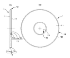
- FIG. 1 shows a glass substrate for a magnetic disk according to the present invention, in which (A) is a side view showing a part of the glass substrate and (B) is a plan view thereof.
- the embodiment of the 2nd processing of the present invention is shown, (A) is a sectional side view showing the state where the peripheral side end face of the glass substrate for magnetic disks is processed using a grindstone, (B) is the plane It is a figure (partial plane sectional view).
- (A) is a sectional side view showing a state in which the inner peripheral side end face of the magnetic disk glass substrate is processed using a grindstone, and (B) is a plan sectional view of the grindstone.
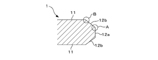
- (A)-(c) is a figure for demonstrating the 1st process of this invention, respectively. It is a perspective view in the state where the 1st processing of the present invention is performed. It is sectional drawing which shows the end surface shape of the glass substrate for magnetic discs.
- a glass substrate for a magnetic disk is usually manufactured through a substrate preparation step, a shape processing step, an end surface polishing step, a main surface grinding step, a main surface polishing step, a chemical strengthening step, and the like.
- the method for manufacturing a glass substrate for a magnetic disk according to the present invention includes an end face processing for processing the end face of the glass substrate.
- the end face processing includes the following first process and a second process performed as a pre-process of the first process.
- the first treatment forms magnetic lines of force using magnetism generating means, forms a mass of the magnetic slurry by holding the magnetic slurry containing the magnetic material and abrasive grains to the magnetic lines of force, and forms the end face of the glass substrate. It is a process processed in the state contacted with the said magnetic slurry lump.
- the second treatment is performed before the first treatment, and both the side wall surface of the end surface of the glass substrate and the chamfered surface between the main surface of the glass substrate and the side wall surface. This is a process in which a grindstone having a groove shape formed so that the surface can be processed at the same time is used, and the glass substrate is processed in an inclined state with respect to the groove direction of the groove shape formed on the grindstone.
- the second process may be referred to as “inclined grinding process” or “inclined grinding process”.
- the first processing may be referred to as “MRF processing” or “MRF processing”.
- MRF is an abbreviation for magnetorheological fluid.
- the shape processing (end face grinding and chamfering) step and the end face polishing step are performed by an end face processing process including the first process and a second process performed as a pre-process of the first process. It can be performed.
- a shape processing step is performed by grinding using a general-purpose grindstone, and then an end surface polishing step is performed by brush polishing.
- the end face processing referred to in the present invention is a process for chamfering the end face of the substrate and creating a desired end face shape including the chamfered face and the side wall face (a process for obtaining shape accuracy).
- the shape processing step is performed by inclined grinding (second processing) as the pre-processing of the first processing, and then by MRF processing (first processing).
- the end surface polishing step is performed.
- variation in the finishing angle of the edge (see A part in FIG. 6) between the chamfered surface 12b and the side wall surface 12a particularly on the end surface of the glass substrate 1 is small, and lines such as polishing streaks are present. It is possible to finish with high quality end face.
- MRF processing enables high-quality polishing.
- pretreatment is the conventional general grindstone processing (the substrate is not inclined with respect to the groove direction of the grindstone)
- the roughness of the grinding surface is low. Since it is high, the machining allowance is increased for low roughness in MRF processing (about 50 ⁇ m, which is the same as that of conventional brush polishing), and the deviation from the shape made with a general-purpose grindstone becomes large. I'll be overwhelmed.
- the substrate end surface is finished in a quasi-mirror surface state that is difficult to realize by the conventional general grinding wheel processing (the substrate is not inclined with respect to the groove direction of the grinding stone), the rounded edges Deterioration of shape accuracy can be prevented and mass productivity can be improved.
- the end surface processing of the present invention it is possible to finish the substrate end surface in a quasi-mirror surface state before MRF processing. Note that in the conventional grindstone processing in which the conventional substrate is not tilted with respect to the groove direction of the grindstone, the trajectory of the grinding stone that comes into contact with the end face is constant, so that the substrate is easily damaged.
- the machining allowance on the side wall surface of the substrate end surface by the above-described inclined grinding is about 10 to 1000 ⁇ m.
- the roughness of the processed surface after the inclined grinding is preferably 1.5 ⁇ m or less at Rmax, and the roughness of the processed surface after the MRF processing is preferably 0.5 ⁇ m or less at Rmax.
- Rmax is calculated according to JIS B0601: 1982.
- the roughness measurement conditions in the present invention are as follows. Measuring device: Laser microscope Measurement area: 50 ⁇ m ⁇ 50 ⁇ m
- the end surface processing in this invention is carrying out the process which chamfers the end surface of a glass substrate using grindstones, such as a total shape, before the said inclination grinding process. That is, the shape processing step is performed by chamfering the end surface using a grindstone such as a general shape and the subsequent inclined grinding processing, and then the end surface polishing step is performed by the MRF processing.
- the burden of the inclined grinding process can be reduced, and even smaller abrasive grains can be used in the inclined grinding process. Therefore, the substrate end surface can be more easily made into a quasi-mirror surface, and the machining allowance for the subsequent MRF process is increased. Can be reduced.
- the finished shape accuracy can be further increased. Specifically, in addition to the small variation in the finishing angle of the edge between the chamfered surface 12b and the side wall surface 12a on the end surface of the glass substrate 1 described above (see part A in FIG. 6), Variations in the finished angle of the edge between the surface 11 and the chamfered surface 12b (see section B in FIG. 6) are reduced, and there are no streaks such as polishing streaks (microscopic observation). is there. In addition, when performing a general-type grindstone process before an inclination grinding process, it is preferable to carry out so that a board
- substrate may not be inclined with respect to the groove direction of a grindstone.
- it may be performed by inclining at an angle different from the inclination angle at the time of the inclined grinding by 2 degrees or more.
- the angle of the trajectory of the grindstone in the general grindstone processing and the slant grinding processing is different, so that the streak due to the two processes cancels out, the end face quality is further improved, and the production efficiency is improved.
- the difference in inclination is smaller than 2 degrees, the above-described canceling effect is reduced, and the quality of the end face may not be improved.
- you may change the angle of inclination substantially by reversing the rotation direction of a board
- the roughness of the processed surface after the inclined grinding is preferably about 1.5 ⁇ m or less in terms of Rmax, and the roughness of the processed surface after the MRF processing is about 0.5 ⁇ m or less in terms of Rmax. It is preferable that In addition, a publicly known method can be used for the total-type grindstone processing in which the substrate is not inclined with respect to the groove direction of the grindstone. It is preferable to use a grindstone containing diamond abrasive grains of # 100 to # 1000.
- the present invention is not limited to the above-described embodiment.
- the above-described inclined grinding process can be applied to the end face polishing process by changing the machining condition from that during grinding.
- FIG. 1 is an overall view of a glass substrate 1 for a magnetic disk to which the present invention is applied, in which (A) is a side view showing a part of the glass substrate in cross section, and (B) is a plan view thereof.
- the glass substrate 1 is formed in a disc (disk) shape as a whole with a circular hole in the center, and has a front and back main surfaces 11, an outer peripheral end surface 12 formed between the main surfaces 11, and an inner surface. And an end face 13 on the circumferential side.
- the end surface 12 on the outer peripheral side of the glass substrate 1 has a side wall surface 12a orthogonal to the main surface 11 and two chamfered surfaces (chamfered surfaces) formed between the side wall surface 12a and the front and back main surfaces 11 respectively.
- the glass substrate 1 is finished to have an outer diameter of 65 mm and an inner diameter of 20 mm.
- the inner diameter is the inner diameter of a circular hole in the center of the glass substrate 1.
- the main surface 11, the outer peripheral side end surface 12, and the inner peripheral side end surface 13 of the magnetic disk glass substrate 1 are polished (mirror polished) so as to have a predetermined surface roughness.
- Both the outer peripheral side end surface 12 and the inner peripheral side end surface 13 are finished to the end face shape as described above, and the surface roughness is finished to a mirror surface state with, for example, Rmax of 1 ⁇ m or less and Ra of 0.1 ⁇ m or less. Is usually required.
- the glass substrate 1 for a magnetic disk is manufactured by sequentially performing each of the above steps on a glass substrate (glass disk) 10 formed into a predetermined disk shape by, for example, direct pressing.
- the inclined grinding process (second process) performed as a pre-process of the above-described MRF process (first process) will be described in detail.
- FIG. 2 shows an embodiment of the second process (inclined grinding) of the present invention, wherein (A) is a side showing a state in which the outer peripheral side end face of the magnetic disk glass substrate is processed using a grindstone.
- Sectional view (B) is a plan view thereof (however, the grinding wheel is a plan sectional view taken along line II-II in FIG. (A)).
- the second treatment is applied to the shape processing step, but can also be applied to the end surface polishing step.
- the case where it applies mainly to a shape processing process is demonstrated.
- the grinding wheel 2 used for grinding the outer peripheral side end face of the glass substrate 10 is formed in a cylindrical shape as a whole and has a groove 3 shape on the inner peripheral side thereof.
- the groove 3 is formed so that both the side wall surface of the outer peripheral side end surface of the glass substrate 10 and the chamfered surface between the main surface and the side wall surface of the glass substrate can be ground simultaneously.
- a groove shape including a side wall portion (side wall surface grinding portion) 3a and chamfer portions (chamfered surface grinding portions) 3b and 3b existing on both sides thereof is provided.
- the side wall 3a and the chamfered portions 3b and 3b of the groove 3 are formed in a predetermined size and shape in consideration of the target size and shape of the ground surface of the glass substrate 10 to be finished.
- the glass substrate 10 has an axis of rotation L 10 passing through the center O 10
- the grinding wheel 2 has a rotary shaft L 2 passing through the center O 2
- the grinding wheel 2 tilt state inner peripheral side inclines the glass substrate 10 relative to the grooves formed 3 groove direction shape of, i.e.
- the glass substrate 10 is ground with a predetermined angle ⁇ , for example, with respect to the groove direction of the groove 3 formed on the inner peripheral side of the grinding wheel 2, so that the end surface of the glass substrate 10 is abutted.
- the trajectory of the grinding wheel 2 in contact with the grinding wheel 2 is not constant, and the convex portion (abrasive grains) of the grinding wheel 2 abuts and acts on the substrate end surface at random positions. Can be finished with higher smoothness.
- the vector of the grinding resistance to the abrasive grains, which are cutting edges, is dispersed, damage can be reduced while maintaining the sharpness, so that there is also an effect of improving the life of the grindstone.
- the inclination angle ⁇ of the glass substrate 10 with respect to the groove direction on the inner peripheral side of the grinding wheel 2 can be arbitrarily set. However, in order to achieve the above-described effects more effectively, for example, in the range of 2 to 15 degrees. It is preferable to be inside. More preferably, it is 10 degrees or less.
- the size of the cylinder of the grinding wheel 2 is What is necessary is just to determine suitably considering the outer diameter of a glass substrate, for example.
- the outer peripheral side end surface 12 of the glass substrate 10 is brought into contact with the inner peripheral side of the grinding wheel 2 and the glass substrate 10 and the grinding wheel 2 are relatively moved, whereby the glass substrate end surface is ground.
- it is advantageous to perform grinding by bringing the outer peripheral side end face 12 of the glass substrate 10 into contact with the inner peripheral side of the grinding wheel 2 and rotating both the glass substrate 10 and the grinding wheel 2. It is.
- the peripheral speeds (tangential speeds) at the processing points of the grinding wheel 2 and the glass substrate 10 do not have to be particularly limited, but from the viewpoint of grindability and processing efficiency, for example, the peripheral speed of the grinding wheel 2 (A) is preferably 1000 to 3000 m / min, and the peripheral speed (B) of the glass substrate 10 is preferably about 5 to 30 m / min. Accordingly, it is preferable in the present invention that the peripheral speed ratio A / B between the grinding wheel 2 and the glass substrate 10 is 80 or more, preferably in the range of 100 to 300.
- the rotating direction of the grinding wheel 2 and the glass substrate 10 may be either a down cut or an up cut.
- a resin grindstone made of abrasive grains and resin can be used.
- a resin grindstone containing diamond abrasive grains as a grindstone.
- a metal grindstone composed of abrasive grains and a metal binder, a vitrified grindstone composed of abrasive grains and a vitreous binder, and a composite grindstone obtained by mixing these binders can also be used.
- abrasive grains are added to a suitable filler as necessary, and bonded to a phenol resin, an epoxy resin, a polyethylene resin, a polystyrene resin, a polyimide resin, or the like, and formed into a predetermined shape. Things can be used. Also, alumina abrasive grains, cubic boron nitride abrasive grains, and the like can be used. As the grain size of the abrasive grains, for example, # 2000 to # 3000 or finer abrasive grains can be suitably used.
- diamond abrasive grains are bonded with resin bonds to form a grindstone during inclined grinding, and it is particularly important to control the bond strength between the abrasive grains and the resin. found. It has been found that this bond strength has a strong influence on grindability (workability) and surface quality during inclined grinding.
- the index is expressed as “grinding wheel elastic modulus”.
- a preferable range of the grindstone elastic modulus is 1500 to 3500 [N / mm]. This parameter is a spring constant, and if it is high, the grindability is good and the dimensional accuracy is improved, but scratches are easily generated. On the other hand, if it is low, the surface quality is improved, but the grinding rate is lowered.
- this grindstone elastic modulus can be evaluated at a load of 15 kgf using a bending strength measuring tester using an HRF indenter.
- the grinding fluid (coolant) used in the present invention is not particularly limited, but a water-soluble grinding fluid having a high cooling effect and high safety at the production site is particularly suitable.
- a groove is formed inside a cylindrical grindstone and coolant is supplied thereto, the retention of the coolant is enhanced, and clogging or clogging of the grindstone can be made difficult to occur. .
- the inclined grinding process to the mirror polishing process of the end face.
- it is performed by the same method as the grinding process except that the elastic modulus of the resin bond grindstone, the type of the grindstone and the grinding liquid, and the peripheral speed ratio of the grindstone and the glass substrate are changed from those during the grinding process. be able to.
- the grindstone elastic modulus of the resin bond grindstone is changed, the mirror surface quality is improved when it is 1500 to 2500 [N / mm]. Therefore, it is suitable when the substrate end surface is mirror-polished by inclined grinding. Further, if it is 2500 to 3500 [N / mm], the shape accuracy and grindability are improved, and therefore, it is suitable for grinding by inclined grinding.
- FIG. 3A is a side sectional view showing a state where the inner peripheral side end face of the glass substrate for magnetic disk is ground using a grinding wheel
- FIG. 3B is a plan sectional view of the grinding wheel ((A ) Is a plan sectional view taken along line III-III in FIG.
- the grinding wheel 4 used for grinding the inner peripheral side end face of the glass substrate 10 has a groove 5 shape.
- the groove 5 is formed so that both the side wall surface of the inner peripheral side end surface of the glass substrate 10 and the chamfered surface between the main surface and the side wall surface of the glass substrate can be ground simultaneously.
- it has a groove shape including a side wall portion (side wall surface grinding portion) 5a and chamfer portions (chamfered surface grinding portions) 5b, 5b existing on both sides thereof.
- the glass substrate 10 is inclined with respect to the groove direction of the groove 5 formed in the grinding wheel 4, that is, the rotation of the glass substrate 10 with respect to the rotation axis L 4 of the grinding wheel 4.
- the grinding wheel 4 is brought into contact with the inner peripheral side end face 13 of the glass substrate 10, and both the glass substrate 10 and the grinding wheel 4 are rotated for grinding.
- the outer peripheral side end surface of the glass substrate is obtained by grinding the inner peripheral side end surface while the glass substrate 10 is inclined, for example, by a predetermined angle ⁇ with respect to the groove direction of the groove 5 shape of the grinding wheel 4.
- a predetermined angle ⁇ with respect to the groove direction of the groove 5 shape of the grinding wheel 4.
- the inclination angle ⁇ of the glass substrate 10 with respect to the groove direction of the grinding wheel 4 can be arbitrarily set, in order to better exhibit the above-described effects, as in the case of grinding of the outer peripheral side end face.
- a range of 2 to 15 degrees is preferable. More preferably, it is 10 degrees or less.
- the peripheral speed and the peripheral speed ratio of each of the grinding wheel 4 and the glass substrate 10 may be appropriately set so as to be suitable for the grinding of the inner peripheral side end face.
- FIGS. 4A to 4C are diagrams for explaining the first processing (MRF processing) of the present invention
- FIG. 5 is a perspective view of the first processing of the present invention. It is.
- the apparatus 20 used for MRF processing in the present invention polishes the end face of a glass substrate using a magnetism generating means and a magnetic slurry. 4 (a) to 4 (c) and FIG. 5 show a case where the outer peripheral side end face of the glass substrate is polished. The outline of the apparatus 20 will be described. As shown in FIG.
- the apparatus 20 includes a pair of magnets 21 and 22 that are permanent magnets, a spacer 23, and a hollow cylinder made of a nonmagnetic material such as stainless steel.
- the end of the glass substrate can be inserted between the magnets 21 and 22 for processing. In this case, the exterior member 24 is not provided.
- the glass substrate 10 that has been subjected to the inclined grinding process is held in a horizontal state by a holder (not shown).
- the glass substrate 10 held by the holder is brought close to the exterior member 24, and a lump 26 (see FIGS. 4C and 5) described later and the outer peripheral side end surface of the glass substrate 10 are brought into contact with each other.
- a holder (not shown) that holds the exterior member 24 and the glass substrate 10 of the apparatus 20 is connected to a drive motor (not shown).
- the outer peripheral end surface of the glass substrate 10 can be polished by rotating the exterior member 24 and the holder to relatively move the outer peripheral end surface of the glass substrate 10 and the magnetic slurry lump 26.
- the rotation directions of the exterior member 24 and the holder for holding the glass substrate 10 are rotated in opposite directions (see FIG. 5), and the relative speed of the peripheral speed between the exterior member 24 and the glass substrate 10 is set to 40 to 100 m / It is preferable to rotate as minutes. If the outer peripheral side end face of the glass substrate 10 and the magnetic slurry lump 26 can be relatively moved, either the glass substrate 10 or the magnetic slurry lump 26 may be fixed and the other may be rotated. In addition, both may be rotated in the same direction.
- the pair of magnets 21 and 22 are close to each other and function as magnetism generating means to form a magnetic force line 25 as shown in FIG.
- the lines of magnetic force 25 proceed so as to protrude outward from the centers of the magnets 21 and 22 and proceed in the thickness direction of the glass substrate 10.
- a pair of magnets arranged in the thickness direction of the glass substrate 10 so that the N-pole surface and the S-pole surface are spaced apart from each other is used as the magnetism generating means. It is done.
- a spacer 23 made of a non-magnetic material is provided between the magnets 21 and 22 in order to set a predetermined separation distance between the N pole end face of the magnet 21 and the S pole end face of the magnet 22.
- the separation distance between the N pole end face of the magnet 21 and the S pole end face of the magnet 22 is set to a predetermined distance by causing the magnetic field lines 25 to protrude outward as shown in FIG. This is because a magnetic slurry lump 26 as shown in FIG.
- a lump of magnetic slurry may be formed between the magnets 21 and 22, and the end of the glass substrate may be brought into contact therewith. Since the magnetic slurry lump 26 is a portion that contacts the outer peripheral side end surface of the glass substrate 10 and moves relative to the end surface, the magnetic slurry lump 26 has a certain degree of magnetic force in order to ensure the rigidity of the magnetic slurry lump 26. Is desired.
- the separation distance between the end face of the N pole of the magnet 21 and the end face of the S pole of the magnet 22 is short, but if it is too short, it becomes difficult to carry out when inserting the glass substrate between the magnets. Therefore, it is preferable that the separation distance between the end face of the N pole of the magnet 21 and the end face of the S pole of the magnet 22 is set within a certain predetermined range.
- a permanent magnet is used as the magnetism generating means.
- an electromagnet may be used.
- the spacer 23 is used in order to ensure a certain distance between the end face of the N pole of the magnet 21 and the end face of the S pole of the magnet 22, but the outer member 24 is not used without using the spacer 23.
- the magnets 21 and 22 are fixed, and the separation distance between the end face of the N pole of the magnet 21 and the end face of the S pole of the magnet 22 can be kept constant.
- polishing the inner peripheral side of a glass substrate when grind
- the polishing conditions may be the same as those on the outer peripheral side.
- a magnetic material is held by magnetic lines of force, and a glass substrate is pressed against the magnetic material to process the substrate surface with the magnetic material.
- the polishing rate and the polishing quality can be improved by the abrasive grains adhering to the magnetic material.
- the magnetic material for example, a magnetic fluid containing magnetic fine particles or the like, or a magnetorheological fluid can be used.
- Nonpolar oil or polar oil containing 3 to 5 g / cm 3 of magnetic fine particles containing an Fe (iron) component having a particle size of 0.1 to 10 ⁇ m, and surface activity A fluid containing an agent is used.
- Nonpolar oil or polar oil has a viscosity of 100 to 1000 (mPa ⁇ sec) at room temperature (20 ° C.), for example.
- the lump 26 formed by the magnetic slurry preferably includes abrasive grains as well as the magnetic particles when the magnetorheological fluid containing the magnetic fine particles is formed as a lump on the lines of magnetic force. Since the abrasive grains in the magnetorheological fluid are pushed out to a portion having a low magnetic force gradient due to the magnetic levitation effect, the abrasive grains are present in the vicinity of the end face of the glass substrate to be polished. And since it becomes a lump which has a comparatively high elastic characteristic with a magnetic force line, it can grind
- abrasive grains contained in the magnetic slurry known abrasive grains of a glass substrate such as cerium oxide, colloidal silica, zirconia oxide, alumina abrasive grains, diamond abrasive grains and the like can be used.
- the particle size of the abrasive grains is, for example, 0.5 to 3 ⁇ m. By using abrasive grains having a particle size in this range, the end face of the glass substrate can be satisfactorily polished.
- the abrasive grains are contained, for example, in an amount of 3 to 15% by volume in the magnetic slurry.
- the viscosity of the magnetic slurry is 1000 to 2000 [mPa ⁇ sec] at room temperature (20 ° C.) by adjusting the concentration of the magnetorheological fluid. This is because the magnetic slurry lump 26 is formed and the end face polishing is performed efficiently. preferable. If the viscosity is low (the concentration of the magnetorheological fluid is low), it is difficult to form the mass 26, and it may be difficult to polish by moving relative to the glass substrate 10 while being pressed against the end face.
- the magnetic flux density in the magnetism generating means is preferably 0.3 to 0.8 [Tesla] from the viewpoint of forming the magnetic slurry lump 26 and performing the end face polishing efficiently.
- the yield stress of the magnetic slurry containing the magnetorheological fluid and the abrasive grains is preferably 30 kPa or more, more preferably 30 to 60 kPa, when a magnetic field of 0.4 [Tesla] is applied.
- the yield stress (yield shear stress) of the magnetorheological fluid can be obtained by, for example, the following method.
- a device incorporating magnetic field application means permanent magnet, electromagnet, etc.
- the yield stress of the magnetorheological fluid can be obtained by approximating the relationship between the obtained shear rate and the shear stress using a known Casson equation.
- the yield stress affects the pressure that the glass substrate receives from the magnetic slurry, that is, the shear stress when the magnetic slurry held by the magnetic field and the edge of the glass substrate move relative to each other. Therefore, the higher the yield stress of the magnetic slurry (the higher the shear stress during the magnetic slurry flow), the more efficiently the polishing by contact between the abrasive grains and the glass substrate can be achieved, and the processing rate can be improved.
- processing can be performed with uniform pressure from the back side of the chamfered surface of the substrate end surface to the side wall surface, which is difficult to process by conventional brush end surface polishing. It is possible to mirror the end shape without disturbing it.
- the amount of bending (bending) of the bristle material changes depending on the location where it comes into contact with the substrate, so that it cannot be processed with uniform pressure.
- the pressure changes with time because the hair material is bent or curved as the number of processing increases. For this reason, the variation in the shape of the end face tends to increase during mass production.
- MRF processing since magnetic lines of force are used instead of brushes, processing can be performed with uniform pressure from the back side of the chamfered surface to the side wall surface. In addition, the pressure does not change over time.
- the machining allowance by MRF machining is, for example, 50 ⁇ m or less, and preferably about 1 to 7 ⁇ m. Further, if the thickness is 5 ⁇ m or less, the shape accuracy is further improved, which is further preferable.
- the end surface processing that combines the first processing (MRF processing) described above and the second processing (inclined grinding processing) performed as a pre-processing of the first processing, It is possible to achieve a high-precision shape and a high-quality surface of the substrate end face than the above method.
- the end surface processing combined with the first processing and the second processing in the present invention is a thick plate (for example, 0.635 mm or more) even if the thickness of the glass substrate put into the end surface processing is, for example, 0.5 mm or less.
- the end face quality equivalent to (1) can be ensured, which is particularly suitable for end face processing of a thin plate.
- the glass constituting the glass substrate is preferably an amorphous aluminosilicate glass.
- a glass substrate can be finished to a smooth mirror surface by mirror polishing the surface, and the strength after processing is good.
- an aluminosilicate glass for example, a glass containing SiO 2 as a main component and containing 20 wt% or less of Al 2 O 3 is preferable. Furthermore, it is more preferable to use glass containing SiO 2 as a main component and containing 15% by weight or less of Al 2 O 3 .
- SiO 2 is 62 wt% to 75 wt%
- Al 2 O 3 is 5 wt% to 15 wt%
- Li 2 O is 4 wt% to 10 wt%
- Na 2 O is 4 wt%.
- % To 12% by weight, ZrO 2 is contained in an amount of 5.5% to 15% by weight as a main component, and the weight ratio of Na 2 O / ZrO 2 is 0.5 to 2.0
- Al 2 O An amorphous aluminosilicate glass containing no phosphorus oxide and having a 3 / ZrO 2 weight ratio of 0.4 to 2.5 can be used.
- SiO 2 is 50 to 75%
- Al 2 O 3 is 0 to 5%
- BaO is 0 to 2%
- Li 2 O is 0 to 3%
- ZnO 0-5% Na 2 O and K 2 O 3-15% in total
- ZrO 2 , TiO 2 , La 2 O 3 , Y 2 O 3 , Yb 2 O 3 , Ta 2 O 5 , Nb 2 O 5 and HfO 2 are included in a total amount of 2 to 9%
- the molar ratio [(MgO + CaO) / (MgO + CaO + SrO + BaO)] is in the range of 0.85 to 1.
- And glass having a molar ratio [Al 2 O 3 / (MgO + CaO)] of 0 to 0.30 can be preferably used. Further, a total of 6 to 15 mol of an alkali metal oxide selected from the group consisting of 56 to 75 mol% of SiO 2 , 1 to 9 mol% of Al 2 O 3 , Li 2 O, Na 2 O and K 2 O.
- the content of Al 2 O 3 in the glass composition is preferably 15% by weight or less. Furthermore, still preferably Al 2 O 3 content is 5 mol% or less.
- the present invention is particularly suitable for end face processing of a glass substrate made of crystallized glass.
- the glass substrate is ground on the main surface for improving the dimensional accuracy and the shape accuracy.
- This main surface grinding is usually performed by using a double-sided grinding device and grinding the main surface of the glass substrate using hard abrasive grains such as diamond. By grinding the main surface of the glass substrate in this way, a predetermined plate thickness and flatness are processed, and a predetermined surface roughness is obtained.
- mirror polishing for obtaining a highly smooth main surface is performed.
- a mirror polishing method for a glass substrate it is preferable to use a polishing pad of a polisher such as polyurethane while supplying a slurry (polishing liquid) containing a metal oxide abrasive such as cerium oxide or colloidal silica. is there.
- a glass substrate having high smoothness is obtained, for example, by polishing with a cerium oxide-based abrasive (first polishing process) and then with final polishing (mirror polishing) (second polishing process) using colloidal silica abrasive grains. It is possible.
- the main surface of the glass substrate after mirror polishing is preferably a mirror surface having an arithmetic average surface roughness Ra of 0.2 nm or less, more preferably 0.13 nm or less.
- Ra and Rmax are roughnesses calculated in accordance with Japanese Industrial Standard (JIS) B0601.
- the surface roughness (for example, the maximum roughness Rmax, the arithmetic average roughness Ra) is practically preferable to be the surface roughness obtained by measuring with an atomic force microscope (AFM). .
- a chemical strengthening treatment after the first polishing process and before the second polishing process.
- a method of the chemical strengthening treatment for example, a low-temperature ion exchange method in which ion exchange is performed in a temperature range not exceeding the glass transition temperature is preferable.
- the chemical strengthening treatment is a process in which a molten chemical strengthening salt is brought into contact with a glass substrate, whereby an alkali metal element having a relatively large atomic radius in the chemical strengthening salt and a relatively small atomic radius in the glass substrate.
- the chemically strengthened glass substrate is excellent in impact resistance, it is particularly preferable for mounting on a HDD for mobile use, for example.
- alkali metal nitrates such as potassium nitrate and sodium nitrate can be preferably used.
- the magnetic disk glass substrate according to the present invention is manufactured.
- the present invention also provides a method for manufacturing a magnetic disk using the above glass substrate for a magnetic disk.
- the magnetic disk is manufactured by forming at least a magnetic layer on the magnetic disk glass substrate according to the present invention.
- a material for the magnetic layer a hexagonal CoCrPt-based or CoPt-based ferromagnetic alloy having a large anisotropic magnetic field can be used.
- a method of forming the magnetic layer it is preferable to use a method of forming a magnetic layer on a glass substrate by a sputtering method, for example, a DC magnetron sputtering method.
- the orientation direction of the magnetic grains of the magnetic layer and the size of the magnetic grains can be controlled.
- a cubic base layer such as a Cr-based alloy
- the magnetization easy direction of the magnetic layer can be oriented along the magnetic disk surface.
- a magnetic disk of the in-plane magnetic recording system is manufactured.
- a hexagonal underlayer containing Ru or Ti for example, the easy magnetization direction of the magnetic layer can be oriented along the normal of the magnetic disk surface.
- a perpendicular magnetic recording type magnetic disk is manufactured.
- the underlayer can be formed by sputtering as with the magnetic layer.
- a protective layer and a lubricating layer may be formed in this order on the magnetic layer.
- the protective layer an amorphous hydrogenated carbon-based protective layer is suitable.
- the protective layer can be formed by a plasma CVD method.
- a lubricant having a functional group at the end of the main chain of the perfluoropolyether compound can be used.
- the main component is a perfluoropolyether compound having a terminal hydroxyl group as a polar functional group.
- the lubricating layer can be applied and formed by a dip method.
- the end surface of the substrate is finished with a high precision shape and high quality, so that the occurrence of failures due to the surface state of the substrate end surface, such as anti-corrosion, is prevented.
- a higher recording density can be realized, and a highly reliable magnetic disk can be obtained.
- Example 1 The following (1) substrate preparation step, (2) shape processing and end surface polishing step, (3) main surface grinding step, (4) main surface polishing step (first polishing step), (5) chemical strengthening step, (6 ) A glass substrate for a magnetic disk of this example was manufactured through a main surface polishing step (second polishing step).
- a glass substrate (glass disk) made of disc-shaped aluminosilicate glass having a diameter of 66 mm ⁇ and a thickness of 1 mm was obtained from molten glass by direct pressing using an upper die, a lower die, and a barrel die.
- a disk-shaped glass substrate may be obtained by cutting out with a grinding wheel from a sheet glass formed by a downdraw method or a float method.
- SiO 2 62 to 75% by weight
- ZrO 2 5.5 to 15% by weight
- Al 2 O 3 5 to 15% by weight
- Li 2 O 4 to 10% by weight
- Na 2 O Glass for chemical strengthening containing 4 to 12% by weight was used.
- the peripheral speed of the grindstone was 2000 m / min, and the peripheral speed of the glass substrate was 20 m / min (thus, the peripheral speed ratio between the grindstone and the glass substrate was 100).
- the inclined grinding process was performed for about 30 seconds.
- the surface roughness of the outer peripheral side end face of the glass substrate at this time was about 1.2 ⁇ m in Rmax for both the side wall face and the chamfered face. Further, the end surface on the inner peripheral side of the substrate was chamfered in the same manner as in the past using a predetermined total type grindstone.
- the outer peripheral side end face of the glass substrate was polished.
- the first treatment (MRF processing) of the present invention was applied to the outer peripheral end surface of the substrate in accordance with the method shown in FIGS.
- a polishing apparatus having a cylindrical exterior member containing two magnets was used.
- the dimensions of the built-in magnet were 216 mm in diameter and 60 mm in thickness.
- a permanent magnet having a magnetic flux density of 6000 gauss was used.
- these two magnets were fixed to the exterior member, and a predetermined separation distance was secured between the magnets.
- the magnetic slurry is obtained by adding 5 ⁇ m of cerium oxide having an average particle diameter of 2 ⁇ m to a magnetorheological fluid in which fine particles of Fe (iron) having an average particle size of 2 ⁇ m are dispersed in nonpolar oil at a density of 3 g / cm 3. What was dispersed at a concentration of volume% was used. And magnetic slurry was supplied along the surface of an exterior member, and the lump of the magnetic slurry raised from the surface of the exterior member was formed. The rotational speed of the exterior member was appropriately adjusted in the range of 20 to 200 rpm, and the rotational speed of the glass substrate was 4000 rpm. The rotational directions of both were opposite to each other as shown in FIG. The processing time was about 3 minutes. Thus, the outer peripheral end face of the substrate was polished by MRF processing. The surface roughness of the outer peripheral end face of the substrate after processing was about 0.1 ⁇ m in Rmax for both the side wall face and the chamfered face.
- the material of the bristle of the polishing brush was 6-6 nylon.
- the rotational speed of this polishing brush was 1400 rpm, and the rotational speed of the glass substrate was 60 rpm in the direction opposite to that of the polishing brush.
- cerium oxide was used as the polishing agent, and a polishing liquid at about 30 ° C. containing this cerium oxide was supplied. Thus, polishing was performed to an Rmax of about 0.5 ⁇ m. And the surface of the glass substrate which finished the said end surface grinding
- the rotation speed of the surface plate was appropriately selected in the range of 10 to 100 rpm, and the load on the glass substrate was set to 100 g / cm 2 .
- the sun gear and the internal gear of the lapping apparatus By rotating the sun gear and the internal gear of the lapping apparatus, both surfaces of the glass substrate housed in the carrier were simultaneously ground.
- the glass substrate that had been subjected to the grinding process was immersed in each of the cleaning baths (applied with ultrasonic waves) of neutral detergent and water in order to perform ultrasonic cleaning.
- a hard polisher (hard foamed urethane) was used as the polisher, and the first polishing step was performed.
- the polishing liquid was water in which cerium oxide was dispersed as an abrasive, and the load was 100 g / cm 2 .
- the glass substrate after the first polishing step was washed and dried.
- Chemical strengthening step chemical strengthening was performed on the glass substrate after the cleaning.
- a chemical strengthening solution prepared by mixing and melting potassium nitrate and sodium nitrate was prepared, and a glass substrate was immersed in the chemical strengthening solution to perform chemical strengthening treatment.
- the second polishing step was performed by replacing the polisher with a polishing pad of soft polisher (suede).
- the surface roughness of the glass substrate main surface is finished to a smooth mirror surface with a Ra of about 0.2 nm or less while maintaining the flat surface obtained in the first polishing step.
- the polishing liquid was water in which colloidal silica was dispersed, and the load was 100 g / cm 2 .
- the glass substrate after the second polishing step was washed and dried.
- a glass substrate was obtained.
- the main surface of the glass substrate was analyzed with an atomic force microscope (AFM) and an electron microscope, it was specular and surface defects such as protrusions and scratches were not observed.
- the obtained glass substrate had an outer diameter of 65 mm, an inner diameter of 20 mm, and a plate thickness of 0.635 mm. Thus, a glass substrate for magnetic disk of this example was obtained.
- Example 1 In the shape processing and end face polishing step of Example 1 above, only MRF processing was performed after the total grinding wheel processing. The conditions for MRF processing were the same as in Example 1. And the glass substrate for magnetic discs was obtained like Example 1 except this shape process and an end surface grinding
- Example 2 In the shape processing and the end surface polishing step of Example 1 described above, only the inclined grinding processing was performed after the total grinding wheel processing. The conditions for the inclined grinding were the same as in Example 1. And the glass substrate for magnetic discs was obtained like Example 1 except this shape process and an end surface grinding
- Example 3 In the shape processing and the end surface polishing step of Example 1 above, only conventional brush polishing was performed after the total grinding wheel processing.
- the conditions for brush polishing were the same as the polishing conditions for the inner peripheral end face in Example 1.
- the glass substrate for magnetic discs was obtained like Example 1 except this shape process and an end surface grinding
- Example 4 In the shape processing and the end surface polishing step of Example 1, the slant grinding processing and the conventional brush polishing were performed after the total grinding wheel processing. The conditions for the slant grinding and brush polishing were the same as in Example 1. And the glass substrate for magnetic discs was obtained like Example 1 except this shape process and an end surface grinding
- Example 1 in which the end face processing of the present invention in which inclined grinding is performed as pre-processing of MRF processing, the variation in the radius of curvature of the edge portion between the chamfered surface and the side wall surface of the substrate end surface after processing is different. It is small and has a well-finished surface state, and can achieve a high-precision shape and a high-quality surface. 2.
- Comparative Example 1 in which only MRF processing was performed after the general grinding wheel processing and in Comparative Example 2 in which only inclined grinding processing was performed after the general grinding wheel processing, particularly in microscopic observation, polishing streaks and the like Streaks remained.
- Comparative Example 3 (conventional example) in which brush grinding is performed after machining of the entire grindstone, since the machining allowance at the time of brush grinding is particularly uneven, the radius of curvature of the edge portion between the chamfered surface and the side wall surface The dispersion of Further, in the microscopic observation, streaks such as polishing streaks were observed. Furthermore, in Comparative Example 4 in which the inclined grinding and brush polishing were performed after the overall grinding wheel processing, the variation in the curvature radius of the edge portion between the chamfered surface and the side wall surface was slightly improved as compared with Comparative Example 3. In the microscopic observation, streaks such as polishing streaks were observed.
- Example 2 In the shape processing and end surface polishing step of Example 1, the first general grinding wheel processing was omitted, and only the inclined grinding processing and MRF processing were performed.
- the conditions of the slant grinding and MRF machining were the same as those in Example 1 except that the machining time was long so that a machining allowance during the slant grinding was sufficient.
- the glass substrate for magnetic discs was obtained like Example 1 except this shape process and an end surface grinding
- the curvature radius variation (Max-Min) of the edge portion was evaluated for the 100 glass substrates thus manufactured.
- Example 2 In the same manner as in Example 1, it was evaluated by a contour shape measuring machine. The results are shown in Table 2, where ⁇ is a variation of 0.02 mm or less, and ⁇ is greater than 0.02 mm and 0.03 mm or less. Further, the same evaluation was performed on the glass substrate of Example 1 above, and the results are shown in Table 2.
- the grindstone at the boundary between the main surface and the chamfered surface (the edge between the main surface and the chamfered surface) is particularly susceptible to damage. Therefore, it is considered that the shape of the edge portion between the main surface and the chamfered surface was likely to vary.
- Example 3 Except for using a glass substrate having a thickness of 0.5 mm, the shape processing and end face polishing steps were performed in the same manner as in Example 1 to produce a magnetic disk glass substrate. Evaluation of the variation in curvature radius of the edge portion between the chamfered surface and the side wall surface at the outer peripheral end surface of the substrate after end surface polishing was performed in the same manner as in Example 1, and the results are shown in Table 3.
- Comparative Example 5 Except for using a glass substrate having a thickness of 0.5 mm, a shape processing and an end surface polishing step were performed in the same manner as in Comparative Example 3 to produce a magnetic disk glass substrate. Variation evaluation of the curvature radius of the edge portion between the chamfered surface and the side wall surface at the outer peripheral end surface of the substrate after end face polishing was performed in the same manner as in Example 1, and the results are shown in Table 3. The same evaluation results in Example 1 and Comparative Example 3 using a glass substrate having a thickness of 0.635 mm are also shown in Table 3.
- Example 4 The following film formation process was performed on the magnetic disk glass substrate obtained in Example 1 to obtain a magnetic disk for perpendicular magnetic recording. That is, an adhesion layer made of a Ti-based alloy thin film, a soft magnetic layer made of a CoTaZr alloy thin film, an underlayer made of a Ru thin film, a perpendicular magnetic recording layer made of a CoCrPt alloy, a carbon protective layer, and a lubricating layer are sequentially formed on the glass substrate. A film was formed.
- the protective layer is for preventing the magnetic recording layer from deteriorating due to contact with the magnetic head, and is made of hydrogenated carbon, and provides wear resistance.
- the lubricating layer was formed by dipping a liquid lubricant of alcohol-modified perfluoropolyether.
- the obtained magnetic disk was installed in an HDD equipped with a DFH head, and a load / unload durability test was conducted for one month while operating the DFH function in a high temperature and high humidity environment of 80 ° C. and 80% RH. There were no particular obstacles and good results were obtained.
- SYMBOLS 1 Glass substrate for magnetic discs 2 Outer peripheral end grinding wheel 4 Inner peripheral end grinding grindstone 3, 5 Groove 10 Disc-shaped glass substrate (glass disc) DESCRIPTION OF SYMBOLS 11 Main surface 12 of glass substrate Outer peripheral side end surface 12a Side wall surface 12b Chamfered surface 13 Glass substrate inner peripheral side end surface 13a Side wall surface 13b Chamfered surface 20 End surface polishing apparatus 21, 22 Magnet 23 Spacer 24 Exterior member 26 Magnetic Lump of slurry
Landscapes
- Engineering & Computer Science (AREA)
- Chemical & Material Sciences (AREA)
- Ceramic Engineering (AREA)
- Inorganic Chemistry (AREA)
- Mechanical Engineering (AREA)
- Manufacturing & Machinery (AREA)
- Manufacturing Of Magnetic Record Carriers (AREA)
- Surface Treatment Of Glass (AREA)
- Grinding And Polishing Of Tertiary Curved Surfaces And Surfaces With Complex Shapes (AREA)
Abstract
本発明はガラス基板の端面を高精度形状及び高品質に仕上げることができる磁気ディスク用ガラス基板の製造方法を提供する。 本発明におけるガラス基板の端面を加工する端面加工処理を以下の第1の処理と、その前工程として行う第2の処理によって行う。 第1の処理は、磁性体と研磨砥粒を含む磁性スラリを磁力線に保持させることによって形成した磁性スラリの塊にガラス基板の端面を接触させた状態で加工する。第2の処理は、ガラス基板の端面の側壁面と面取面の両方の面を同時に加工できるように形成された溝形状を有する砥石を用い、該砥石の溝形状の方向に対してガラス基板を傾けた状態で加工する。
Description
本発明は、ハードディスクドライブ(HDD)等の磁気ディスク装置に搭載される磁気ディスク用ガラス基板の製造方法および磁気ディスクの製造方法に関する。
ハードディスクドライブ(HDD)等の磁気ディスク装置に搭載される情報記録媒体の一つとして磁気ディスクがある。磁気ディスクは、基板上に磁性層等の薄膜を形成して構成されたものであり、その基板として従来はアルミ基板が用いられてきた。しかし、最近では、高記録密度化の追求に呼応して、アルミ基板と比べて磁気ヘッドと磁気ディスクとの間隔をより狭くすることが可能なガラス基板の占める比率が次第に高くなってきている。また、ガラス基板表面は磁気ヘッドの浮上高さを極力下げることができるように、高精度に研磨して高記録密度化を実現している。近年、HDDの更なる大記録容量化、低価格化の要求は増すばかりであり、これを実現するためには、磁気ディスク用ガラス基板においても更なる高品質化、低コスト化が必要になってきている。
磁気ディスク用ガラス基板は、通常、ディスク状に形成したガラス基板に、形状加工(端面研削及び面取り)、端面研磨、主表面研削、主表面研磨、化学強化等の工程を順次施して製造される。
上記のように安価で高記録密度を達成できる磁気ディスクが求められているが、磁気ディスクの高記録密度化のためには、ガラス基板の加工精度にも高度なものが要求されており、それはガラス基板の主表面のみならず、端面形状においても同様である。
上記のように安価で高記録密度を達成できる磁気ディスクが求められているが、磁気ディスクの高記録密度化のためには、ガラス基板の加工精度にも高度なものが要求されており、それはガラス基板の主表面のみならず、端面形状においても同様である。
下記特許文献1に開示されているように、従来一般的には、磁気ディスク用ガラス基板の端面は、総型砥石を用いた端面研削加工を行った後、ブラシ端面研磨を行うことにより加工されていた。
また、下記特許文献2には、フェライト系磁性粒子と研磨砥粒を含むスラリに磁場を加えることにより、磁気ディスク用ガラス基板の端面を研磨する方法が開示されている。
また、下記特許文献2には、フェライト系磁性粒子と研磨砥粒を含むスラリに磁場を加えることにより、磁気ディスク用ガラス基板の端面を研磨する方法が開示されている。
上記のとおり、安価で高記録密度を達成できる磁気ディスクが求められており、そのためには、基板の外径端面に関しては、媒体主表面に対するコロージョン発生などのコンタミ要因の低減要請に基づく高品位化、ディスクフラッタ(バタツキ)低減のための高精度化の両方の達成が要求されている。
しかしながら、上述した従来の総型砥石を用いた端面研削加工を行った後、ブラシ端面研磨を行うことによりガラス基板の端面を加工する方法では、特に基板端面における面取面と側壁面間のエッジ角度のばらつきが大きく、これが以前は問題とはならなかったレベルのOD(外径)エッジダメージ(微細なキズ)の原因となり、ここに砥粒等の異物を噛み込むことによって磁気ディスクやハードディスクドライブ(HDD)の歩留りを低下させていた。換言すると、せっかく総型砥石でエッジ形状を作りこんでも、その後のブラシ研磨により丸まり方にばらつきが生じていたため、上記エッジ角度にばらつきが生じていた。また、ODエッジダメージは、主表面の研磨処理中に基板の側壁面がキャリアと接触して発生するが、研究の結果、エッジ角度のばらつきが大きかったり、側壁面の傾きが主表面に垂直でなかったり、長さが短かったりすると、キャリアと局所的に強く接触して発生しやすいことが判明した。特に、ブラシ端面研磨においては、ブラシの毛材の曲がり方が異なることによって面取面の奥側(主表面近傍)と側壁面にかかる圧力が異なるため、取代が不均一となりやすく、面取面と側壁面間のエッジの角度が乱れ易いという問題があった。また、ブラシ端面研磨では、端面の鏡面化はできるものの、線状の研磨条痕が残り易いという問題があった。
また、上述の特許文献2に開示されたフェライト系磁性粒子と研磨砥粒を含むスラリに磁場を加えることにより、磁気ディスク用ガラス基板の端面を研磨する方法では、磁石の配置等の点で装置構成が複雑であり、また磁石と磁性粒子との距離が遠く、スラリが十分に保持できないため加工レートが小さく、さらにはこの方法では基板の外周側端面を研磨することができないという不具合もある。
近年、より一層の高情報記録密度化などの観点から、ガラス基板の端面の寸法形状精度や面取り加工の仕上がり面品位など、磁気ディスク用ガラス基板に対する品質要求は従来に増して高まる一方であり、従来の研削方法や研磨方法を用いて多数枚の磁気ディスク用ガラス基板を製造した場合、高まるガラス基板の品質要求に安定的に応えることが次第に困難になってきているという問題がある。
そこで、本発明は、高記録密度化への信頼性の確保が急務となっている磁気ディスクの高記録密度化の要請に応える観点から、特に磁気ディスク用ガラス基板の端面を高精度形状及び高品質に仕上げることができる安定した加工を可能とする磁気ディスク用ガラス基板の製造方法、およびそれによって得られるガラス基板を利用した磁気ディスクの製造方法を提供することを目的とする。
上記課題を解決するため、本発明は以下の構成を有する。
(構成1)
ガラス基板の端面を加工する端面加工処理を含む磁気ディスク用ガラス基板の製造方法であって、前記端面加工処理は、磁気発生手段を用いて磁力線を形成し、磁性体と研磨砥粒を含む磁性スラリを前記磁力線に保持させることによって前記磁性スラリの塊を形成し、前記ガラス基板の端面を前記磁性スラリの塊と接触させた状態で加工する第1の処理と、該第1の処理の前加工として行われる、前記ガラス基板の端面の側壁面と、該ガラス基板の主表面と前記側壁面との間の面取面との両方の面を同時に加工できるように形成された溝形状を有する砥石を用い、該砥石に形成された前記溝形状の溝方向に対して前記ガラス基板を傾けた状態で加工する第2の処理とを含むことを特徴とする磁気ディスク用ガラス基板の製造方法。
(構成1)
ガラス基板の端面を加工する端面加工処理を含む磁気ディスク用ガラス基板の製造方法であって、前記端面加工処理は、磁気発生手段を用いて磁力線を形成し、磁性体と研磨砥粒を含む磁性スラリを前記磁力線に保持させることによって前記磁性スラリの塊を形成し、前記ガラス基板の端面を前記磁性スラリの塊と接触させた状態で加工する第1の処理と、該第1の処理の前加工として行われる、前記ガラス基板の端面の側壁面と、該ガラス基板の主表面と前記側壁面との間の面取面との両方の面を同時に加工できるように形成された溝形状を有する砥石を用い、該砥石に形成された前記溝形状の溝方向に対して前記ガラス基板を傾けた状態で加工する第2の処理とを含むことを特徴とする磁気ディスク用ガラス基板の製造方法。
(構成2)
前記第2の処理の前に、前記ガラス基板の端面に面取面を形成する処理を行うことを特徴とする構成1に記載の磁気ディスク用ガラス基板の製造方法。
(構成3)
前記面取面を形成する処理と、前記第2の処理とは、基板に対する砥石の溝方向がそれぞれ異なる角度で行われることを特徴とする構成2に記載の磁気ディスク用ガラス基板の製造方法。
前記第2の処理の前に、前記ガラス基板の端面に面取面を形成する処理を行うことを特徴とする構成1に記載の磁気ディスク用ガラス基板の製造方法。
(構成3)
前記面取面を形成する処理と、前記第2の処理とは、基板に対する砥石の溝方向がそれぞれ異なる角度で行われることを特徴とする構成2に記載の磁気ディスク用ガラス基板の製造方法。
(構成4)
前記端面加工処理後の前記ガラス基板の端面の表面粗さがRmaxで0.2μm以下であることを特徴とする構成1乃至3のいずれかに記載の磁気ディスク用ガラス基板の製造方法。
(構成5)
前記端面加工処理に投入する前記ガラス基板の板厚が0.5mm以下であることを特徴とする構成1乃至4のいずれかに記載の磁気ディスク用ガラス基板の製造方法。
前記端面加工処理後の前記ガラス基板の端面の表面粗さがRmaxで0.2μm以下であることを特徴とする構成1乃至3のいずれかに記載の磁気ディスク用ガラス基板の製造方法。
(構成5)
前記端面加工処理に投入する前記ガラス基板の板厚が0.5mm以下であることを特徴とする構成1乃至4のいずれかに記載の磁気ディスク用ガラス基板の製造方法。
(構成6)
前記ガラス基板は結晶化ガラスからなることを特徴とする構成1乃至5のいずれかに記載の磁気ディスク用ガラス基板の製造方法。
(構成7)
構成1乃至6のいずれかに記載の磁気ディスク用ガラス基板の製造方法により製造された磁気ディスク用ガラス基板上に、少なくとも磁気記録層を形成することを特徴とする磁気ディスクの製造方法。
前記ガラス基板は結晶化ガラスからなることを特徴とする構成1乃至5のいずれかに記載の磁気ディスク用ガラス基板の製造方法。
(構成7)
構成1乃至6のいずれかに記載の磁気ディスク用ガラス基板の製造方法により製造された磁気ディスク用ガラス基板上に、少なくとも磁気記録層を形成することを特徴とする磁気ディスクの製造方法。
本発明によれば、磁気ディスクのより一層の高記録密度化の要請に応える観点から、磁気ディスク用ガラス基板の端面の寸法形状精度や面取り加工の仕上がり面品位などを確保でき、端面を高精度形状及び高品質に仕上げることができる安定した端面加工が可能であり、基板端面が高精度形状及び高品質に仕上げられた磁気ディスク用ガラス基板を安定して提供することが可能になる。
さらに、この磁気ディスク用ガラス基板の製造方法によって製造された磁気ディスク用ガラス基板を用いることにより、基板の端面が高精度形状及び高品質に仕上げられているため、コロージョン対策など、基板端面の表面状態が起因する障害の発生を防止し、より一層の高記録密度化を実現でき、且つ信頼性の高い磁気ディスクを提供することができる。
以下、本発明の実施の形態を詳述する。
磁気ディスク用ガラス基板は、通常、基板準備工程、形状加工工程、端面研磨工程、主表面研削工程、主表面研磨工程、化学強化工程、等を経て製造される。
本発明の磁気ディスク用ガラス基板の製造方法においては、ガラス基板の端面を加工する端面加工処理を含む。そして、この端面加工処理は、以下の第1の処理と、該第1の処理の前工程として行われる第2の処理とを含む。
磁気ディスク用ガラス基板は、通常、基板準備工程、形状加工工程、端面研磨工程、主表面研削工程、主表面研磨工程、化学強化工程、等を経て製造される。
本発明の磁気ディスク用ガラス基板の製造方法においては、ガラス基板の端面を加工する端面加工処理を含む。そして、この端面加工処理は、以下の第1の処理と、該第1の処理の前工程として行われる第2の処理とを含む。
第1の処理は、磁気発生手段を用いて磁力線を形成し、磁性体と研磨砥粒を含む磁性スラリを前記磁力線に保持させることによって前記磁性スラリの塊を形成し、前記ガラス基板の端面を前記磁性スラリの塊と接触させた状態で加工する処理である。
また、第2の処理は、上記第1の処理の前に行われ、前記ガラス基板の端面の側壁面と、該ガラス基板の主表面と前記側壁面との間の面取面との両方の面を同時に加工できるように形成された溝形状を有する砥石を用い、該砥石に形成された前記溝形状の溝方向に対して前記ガラス基板を傾けた状態で加工する処理である。
また、第2の処理は、上記第1の処理の前に行われ、前記ガラス基板の端面の側壁面と、該ガラス基板の主表面と前記側壁面との間の面取面との両方の面を同時に加工できるように形成された溝形状を有する砥石を用い、該砥石に形成された前記溝形状の溝方向に対して前記ガラス基板を傾けた状態で加工する処理である。
上記第1の処理および第2の処理の詳細は後で詳しく説明する。なお、説明の便宜上、以下、上記第2の処理のことを「傾斜研削加工」或いは「傾斜研削加工処理」と呼ぶこともある。また、上記第1の処理のことを「MRF加工」或いは「MRF加工処理」と呼ぶこともある。ここで、MRFとは磁気粘性流体の略称である。
本発明においては、上記第1の処理と、その前に第1の処理の前加工として行う第2の処理とを含む端面加工処理によって、上記形状加工(端面研削及び面取り)工程および端面研磨工程を行うことができる。従来は、総型砥石を用いた研削加工により形状加工工程を行い、その後のブラシ研磨により端面研磨工程を行っていた。
なお、本発明でいう端面加工処理とは、基板端面の面取りを行うとともに、面取面と側壁面を含む所望の端面形状に作りこむ処理(形状精度を出す処理)である。
本発明においては、上記第1の処理と、その前に第1の処理の前加工として行う第2の処理とを含む端面加工処理によって、上記形状加工(端面研削及び面取り)工程および端面研磨工程を行うことができる。従来は、総型砥石を用いた研削加工により形状加工工程を行い、その後のブラシ研磨により端面研磨工程を行っていた。
なお、本発明でいう端面加工処理とは、基板端面の面取りを行うとともに、面取面と側壁面を含む所望の端面形状に作りこむ処理(形状精度を出す処理)である。
本発明における端面加工処理の一実施の形態は、上記第1の処理の前加工として傾斜研削加工(第2の処理)によって上記形状加工工程を行い、続いてMRF加工(第1の処理)によって上記端面研磨工程を行うことである。このような実施の形態によれば、特にガラス基板1の端面における面取面12bと側壁面12a間のエッジ(図6のA部参照)の仕上がり角度のばらつきが小さく、研磨条痕等の筋目が無く、高品位の端面に仕上げることが可能である。
MRF加工は高品質な研磨が可能であるが、その前処理(前加工)が従来の総型砥石加工(基板を砥石の溝方向に対して傾斜させない)の場合には研削面の粗さが高いため、MRF加工において低粗さとするには取代が多くなってしまい(従来のブラシ研磨と同等の50μm程度)、総型砥石で作りこんだ形状からの乖離が大きくなり、例えばエッジが大きく丸まったりしてしまう。そこで、MRF加工の前に、基板端面を、従来の総型砥石加工(基板を砥石の溝方向に対して傾斜させない)では実現困難であった準鏡面状態に仕上げておくと、エッジの丸まりによる形状精度の悪化を防止するとともに量産性を改善することができる。本発明の端面加工処理によれば、MRF加工の前に、基板端面を準鏡面状態に仕上げておくことが可能である。
なお、従来の基板を砥石の溝方向に対して傾斜させない総型砥石加工では、端面に当接する研削砥石の軌跡が一定となるため、基板へのダメージが入りやすいという事情があった。また、研削砥石の軌跡が一定となるため、砥石に目潰れや目詰まりが発生しやすいため、砥石に用いる砥粒を小さくできないという事情もあった。これらの要因により、従来の基板を砥石の溝方向に対して傾斜させない総型砥石加工では、加工後の表面を準鏡面に仕上げることが困難であった。
なお、従来の基板を砥石の溝方向に対して傾斜させない総型砥石加工では、端面に当接する研削砥石の軌跡が一定となるため、基板へのダメージが入りやすいという事情があった。また、研削砥石の軌跡が一定となるため、砥石に目潰れや目詰まりが発生しやすいため、砥石に用いる砥粒を小さくできないという事情もあった。これらの要因により、従来の基板を砥石の溝方向に対して傾斜させない総型砥石加工では、加工後の表面を準鏡面に仕上げることが困難であった。
本実施の形態においては、上記傾斜研削加工による基板端面の側壁面での加工取代は、10~1000μm程度である。また、上記傾斜研削加工後の加工面の粗さは、Rmaxで1.5μm以下とすることが好ましく、上記MRF加工後の加工面の粗さは、Rmaxで0.5μm以下とすることが好ましい。
なお、Rmaxについては、JIS B0601:1982に従って算出される。また、本発明における粗さ測定条件は以下のとおりである。
測定装置:レーザー顕微鏡
測定領域:50μm×50μm
なお、Rmaxについては、JIS B0601:1982に従って算出される。また、本発明における粗さ測定条件は以下のとおりである。
測定装置:レーザー顕微鏡
測定領域:50μm×50μm
また、本発明における端面加工処理の他の実施の形態としては、上記傾斜研削加工の前に、総型形状等の砥石を用いてガラス基板の端面を面取り加工する処理を行うことである。つまり、総型形状等の砥石を用いた端面の面取り加工とその後の上記傾斜研削加工によって上記形状加工工程を行い、続いて上記MRF加工によって上記端面研磨工程を行う。
このような実施の形態によれば、傾斜研削加工の負担を減らすことができ、傾斜研削加工においてさらに小さい砥粒を使用できるので、基板端面をさらに準鏡面にしやすくなり、その後のMRF加工の取代が減らせる。その結果、仕上がりの形状精度をさらに高めることが可能である。具体的には、上述のガラス基板1の端面における面取面12bと側壁面12a間のエッジ(図6のA部参照)の仕上がり角度のばらつきが小さくなることに加えて、ガラス基板1の主表面11と面取面12b間のエッジ(図6のB部参照)の仕上がり角度のばらつきも小さくなり、さらに研磨条痕等の筋目が無く(顕微鏡観察)高品位の端面に仕上げることが可能である。
なお、傾斜研削加工の前に総型砥石加工を行う場合、基板を砥石の溝方向に対して傾斜させないようにして行うことが好ましい。または、傾斜研削加工時の傾斜角度と2度以上異なる角度で傾斜させて行ってもよい。このようにすることで、総型砥石加工と傾斜研削加工における砥石の軌跡の角度が異なるので、2つの加工による筋目が打ち消しあって端面の品位をさらに向上させられるとともに、生産効率もよくなる。傾斜の差が2度より小さい場合、上記の打ち消しあう効果が小さくなり、端面の品位が向上しない場合がある。なお、基板と砥石の回転方向を逆にすることによって実質的に傾斜の角度を変えてもよい。
本実施の形態においては、上記傾斜研削加工後の加工面の粗さは、Rmax で1.5μm以下程度とすることが好ましく、上記MRF加工後の加工面の粗さは、Rmaxで 0.5μm以下程度とすることが好ましい。
なお、基板を砥石の溝方向に対して傾斜させない総型砥石加工は、公知の方法を用いることができる。砥石としては#100~#1000のダイヤモンド砥粒を含むものを用いることが好ましい。
このような実施の形態によれば、傾斜研削加工の負担を減らすことができ、傾斜研削加工においてさらに小さい砥粒を使用できるので、基板端面をさらに準鏡面にしやすくなり、その後のMRF加工の取代が減らせる。その結果、仕上がりの形状精度をさらに高めることが可能である。具体的には、上述のガラス基板1の端面における面取面12bと側壁面12a間のエッジ(図6のA部参照)の仕上がり角度のばらつきが小さくなることに加えて、ガラス基板1の主表面11と面取面12b間のエッジ(図6のB部参照)の仕上がり角度のばらつきも小さくなり、さらに研磨条痕等の筋目が無く(顕微鏡観察)高品位の端面に仕上げることが可能である。
なお、傾斜研削加工の前に総型砥石加工を行う場合、基板を砥石の溝方向に対して傾斜させないようにして行うことが好ましい。または、傾斜研削加工時の傾斜角度と2度以上異なる角度で傾斜させて行ってもよい。このようにすることで、総型砥石加工と傾斜研削加工における砥石の軌跡の角度が異なるので、2つの加工による筋目が打ち消しあって端面の品位をさらに向上させられるとともに、生産効率もよくなる。傾斜の差が2度より小さい場合、上記の打ち消しあう効果が小さくなり、端面の品位が向上しない場合がある。なお、基板と砥石の回転方向を逆にすることによって実質的に傾斜の角度を変えてもよい。
本実施の形態においては、上記傾斜研削加工後の加工面の粗さは、Rmax で1.5μm以下程度とすることが好ましく、上記MRF加工後の加工面の粗さは、Rmaxで 0.5μm以下程度とすることが好ましい。
なお、基板を砥石の溝方向に対して傾斜させない総型砥石加工は、公知の方法を用いることができる。砥石としては#100~#1000のダイヤモンド砥粒を含むものを用いることが好ましい。
なお、本発明は上述の実施の形態にはもちろん限定されない。たとえば、上記傾斜研削加工は、加工条件を研削時とは変更することによって端面研磨加工に適用することも可能である。
図1は、本発明が適用される磁気ディスク用ガラス基板1の全体図であり、(A)はその一部を断面で示した側面図、(B)はその平面図である。該ガラス基板1は、中心部に円孔を有する全体がディスク(円板)状に形成され、その表裏の主表面11と、これら主表面11間に形成される外周側の端面12と、内周側の端面13とを有する。
上記ガラス基板1の外周側の端面12は、その主表面11と直交する側壁面12aと、この側壁面12aと表裏の主表面11との間にそれぞれ形成されている2つの面取面(面取りした面)12b、12bとからなる形状に形成されている。また、上記ガラス基板1の内周側の端面13についても、その主表面11と直交する側壁面13aと、この側壁面13aと表裏の主表面11との間にそれぞれ形成されている2つの面取面(面取りした面)13b、13bとからなる形状に形成されている。
そして磁気ディスク、例えば、2.5インチディスクの場合は、ガラス基板1の外径が65mm、内径が20mmに仕上げられる。ここで、内径とは、ガラス基板1の中心部の円孔の内径のことである。
上記ガラス基板1の外周側の端面12は、その主表面11と直交する側壁面12aと、この側壁面12aと表裏の主表面11との間にそれぞれ形成されている2つの面取面(面取りした面)12b、12bとからなる形状に形成されている。また、上記ガラス基板1の内周側の端面13についても、その主表面11と直交する側壁面13aと、この側壁面13aと表裏の主表面11との間にそれぞれ形成されている2つの面取面(面取りした面)13b、13bとからなる形状に形成されている。
そして磁気ディスク、例えば、2.5インチディスクの場合は、ガラス基板1の外径が65mm、内径が20mmに仕上げられる。ここで、内径とは、ガラス基板1の中心部の円孔の内径のことである。
また、磁気ディスク用ガラス基板1の主表面11、外周側端面12、内周側端面13は、それぞれ所定の表面粗さとなるように研磨(鏡面研磨)仕上げされる。外周側端面12及び内周側端面13はいずれも、上述のような端面形状に仕上げられ、なお且つ、表面粗さが例えばRmaxで1μm以下、Raで0.1μm以下の鏡面状態に仕上げられることが通常求められる。
前記のとおり、磁気ディスク用ガラス基板1は、例えばダイレクトプレス等により所定のディスク状に成形したガラス基板(ガラスディスク)10に、上記の各工程を順次施して製造される。
ここで、上述のMRF加工(第1の処理)の前加工として実施される傾斜研削加工(第2の処理)について詳しく説明する。
図2は、本発明の第2の処理(傾斜研削加工)の実施形態を示すもので、(A)は砥石を用いて磁気ディスク用ガラス基板の外周側端面を加工している状態を示す側断面図、(B)はその平面図(但し、研削砥石については(A)図におけるII-II線に沿った平断面図である)である。上記のとおり、本発明において、第2の処理は形状加工工程に適用されるが、端面研磨工程に適用されることも可能である。ここでは主に形状加工工程に適用される場合を説明する。
ここで、上述のMRF加工(第1の処理)の前加工として実施される傾斜研削加工(第2の処理)について詳しく説明する。
図2は、本発明の第2の処理(傾斜研削加工)の実施形態を示すもので、(A)は砥石を用いて磁気ディスク用ガラス基板の外周側端面を加工している状態を示す側断面図、(B)はその平面図(但し、研削砥石については(A)図におけるII-II線に沿った平断面図である)である。上記のとおり、本発明において、第2の処理は形状加工工程に適用されるが、端面研磨工程に適用されることも可能である。ここでは主に形状加工工程に適用される場合を説明する。
上記ガラス基板10の外周側端面の研削加工に用いる研削砥石2は、全体が円筒状に形成されているとともにその内周側に溝3形状を有する。該溝3は、上記ガラス基板10の外周側端面の側壁面と、該ガラス基板の主表面と側壁面との間の面取面との両方の面を同時に研削加工できるように形成されており、具体的には、側壁部(側壁面研削加工部)3a及びその両側に存在する面取部(面取面研削加工部)3b,3bからなる溝形状を備えている。上記溝3の側壁部3a及び面取部3b,3bは、ガラス基板10の研削加工面の仕上がり目標の寸法形状を考慮して、所定の寸法形状に形成されている。
そして、本実施の形態では、研削砥石2の内周側に形成された溝3形状の溝方向に対してガラス基板10を傾けた状態で研削加工する。
図2を参照して説明すると、ガラス基板10はその中心O10を通る回転軸L10を有し、研削砥石2はその中心O2を通る回転軸L2を有しており、研削砥石2の内周側に形成された溝3形状の溝方向に対してガラス基板10を傾けた状態、つまり研削砥石2の回転軸L2に対してガラス基板10の回転軸L10を角度αだけ傾けた状態で、研削砥石2の内周側にガラス基板10の外周側端面12を接触させながら、ガラス基板10と研削砥石2の両方を回転させて研削加工を行う。
図2を参照して説明すると、ガラス基板10はその中心O10を通る回転軸L10を有し、研削砥石2はその中心O2を通る回転軸L2を有しており、研削砥石2の内周側に形成された溝3形状の溝方向に対してガラス基板10を傾けた状態、つまり研削砥石2の回転軸L2に対してガラス基板10の回転軸L10を角度αだけ傾けた状態で、研削砥石2の内周側にガラス基板10の外周側端面12を接触させながら、ガラス基板10と研削砥石2の両方を回転させて研削加工を行う。
このように、研削砥石2の内周側に形成された溝3形状の溝方向に対してガラス基板10を例えば所定角度αだけ傾けた状態で研削加工することにより、ガラス基板10の端面に当接する研削砥石2の軌跡が一定とはならないで、研削砥石2の凸部(砥粒)が基板端面に対してランダムな位置に当接、作用するため、基板へのダメージが少なく、研削加工面をより高平滑に仕上げることができる。さらに、切れ刃である砥粒への研削抵抗のベクトルが分散されることで切れ味を持続させながらダメージを軽減できることで砥石寿命の向上効果も有する。この砥石寿命の向上により、研削加工の経時変化が小さくなるため、形状精度も向上する。
上述の研削砥石2の内周側の溝方向に対するガラス基板10の傾斜角度αは任意に設定することができるが、上述の作用効果をより良く発揮させるためには、例えば2~15度の範囲内とすることが好適である。10度以下とするとより好ましい。
上述の研削砥石2の内周側の溝方向に対するガラス基板10の傾斜角度αは任意に設定することができるが、上述の作用効果をより良く発揮させるためには、例えば2~15度の範囲内とすることが好適である。10度以下とするとより好ましい。
なお、本実施の形態では、研削砥石2の内周側にガラス基板10の外周側端面12を接触させることにより、ガラス基板端面の研削加工を行うため、研削砥石2の円筒の大きさは、ガラス基板の例えば外径を考慮して適宜決定されればよい。
また、研削砥石2の内周側にガラス基板10の外周側端面12を接触させ且つガラス基板10と研削砥石2とを相対的に移動させることにより、ガラス基板端面の研削加工を行うが、たとえば量産性を上げるためには、研削砥石2の内周側にガラス基板10の外周側端面12を接触させなお且つガラス基板10と研削砥石2の両方を回転させることにより研削加工を行うことが有利である。
この場合、研削砥石2とガラス基板10の加工点における夫々の周速度(接線方向の速度)は特に制約する必要はないが、研削性や加工能率の観点からは、例えば研削砥石2の周速度(Aとする)は、1000~3000m/分、ガラス基板10の周速度(Bとする)は、5~30m/分程度とすることが好適である。したがって、研削砥石2とガラス基板10の周速度比A/Bが、80以上、好ましくは100~300の範囲内であることが本発明においては好適である。
なお、研削砥石2とガラス基板10の回転方向は、ダウンカット、アップカットのいずれでもよい。
なお、研削砥石2とガラス基板10の回転方向は、ダウンカット、アップカットのいずれでもよい。
本発明に使用する上記研削砥石2としては、砥粒と樹脂とからなるレジン砥石を用いることができる。磁気ディスク用ガラス基板の端面の面取り加工には、研削砥石としてダイヤモンド砥粒を含むレジン砥石を用いるのが好適である。また、砥粒と金属結合材からなるメタル砥石、砥粒とガラス質結合材からなるビトリファイド砥石、及びそれらの結合材を混合させた複合砥石を用いることもできる。特にレジン砥石としては、例えばダイヤモンド砥粒を、必要に応じて適当な充填材を加えて、フェノール樹脂、エポキシ樹脂、ポリエチレン樹脂、ポリスチレン樹脂、またはポリイミド樹脂等で結合して所定の形状に成形したものを用いることができる。また、アルミナ砥粒、立方晶窒化ホウ素砥粒などを用いることもできる。砥粒の粒度は、例えば#2000~#3000や、さらにこれより微細な砥粒を好適に用いることができる。本発明の場合、加工面品位の向上の観点からは有利な微細砥粒砥石を用いた場合にも、砥石の切れ味を持続させ、安定した研削性を確保でき、良好な研削面品位(鏡面品位)と良好な寸法形状精度を安定的に得ることができる。
なお上記のとおり、傾斜研削加工時にはダイヤモンド砥粒をレジンボンドで結合させて砥石を形成するのが好ましいが、さらにその際、砥粒と樹脂の結合強度を制御することが特に重要であることが判明した。この結合強度が傾斜研削加工時の研削性(加工性)及び表面品質に強く影響することが判明した。
ここでは、その指標を「砥石弾性率」として表す。
砥石弾性率の好ましい範囲は、1500~3500[N/mm]である。このパラメータはバネ定数的なものであり、高いと研削性は良好になり寸法精度もよくなるがキズが入り易くなる。一方、低いと表面品質はよくなるが研削レートが低下する。
この砥石弾性率を変化させることで、傾斜研削加工を形状精度優先とするか、表面品質優先とするかを調節することができる。すなわち、砥石弾性率を高くした場合は、形状精度と加工レートに有利である。一方、砥石弾性率を低くした場合は、表面品質に有利である。
なお、この砥石弾性率は、HRF圧子を用い、抗折強度測定試験機にて荷重15kgfで評価することができる。
ここでは、その指標を「砥石弾性率」として表す。
砥石弾性率の好ましい範囲は、1500~3500[N/mm]である。このパラメータはバネ定数的なものであり、高いと研削性は良好になり寸法精度もよくなるがキズが入り易くなる。一方、低いと表面品質はよくなるが研削レートが低下する。
この砥石弾性率を変化させることで、傾斜研削加工を形状精度優先とするか、表面品質優先とするかを調節することができる。すなわち、砥石弾性率を高くした場合は、形状精度と加工レートに有利である。一方、砥石弾性率を低くした場合は、表面品質に有利である。
なお、この砥石弾性率は、HRF圧子を用い、抗折強度測定試験機にて荷重15kgfで評価することができる。
また、ガラス材料は研削加工時に発生する熱による影響を受けやすい加工特性を有するため、安定した研削加工を可能とならしめるためには、ガラス基板の端面部分に供給する研削液(クーラント)による冷却効果を高めて、研削加工時の熱による影響をできるだけ軽減することが望ましい。本発明に使用する研削液(クーラント)としては、特に制約はないが、冷却効果が高く、生産現場において安全性の高い水溶性の研削液が特に好適である。なお、本発明のように、円筒形の砥石の内側に溝を形成しておき、そこにクーラントを供給すると、クーラントの保持性が高まり、砥石の目詰まりや目つぶれを起こしにくくすることができる。
また、上記のとおり傾斜研削加工を端面の鏡面研磨工程に適用することも可能である。この場合、たとえばレジンボンド砥石の砥石弾性率や、砥石及び研削液の種類、砥石とガラス基板の周速度比を前記研削加工時とは変更すること以外は、前記研削加工と同様な方法により行うことができる。
レジンボンド砥石の砥石弾性率を変更する場合、1500~2500[N/mm]とすると鏡面品位が向上するため、傾斜研削加工で基板端面を鏡面研磨する場合に好適である。また、2500~3500[N/mm]とすると形状精度及び研削性が向上するため、傾斜研削加工で研削加工する場合に好適である。
レジンボンド砥石の砥石弾性率を変更する場合、1500~2500[N/mm]とすると鏡面品位が向上するため、傾斜研削加工で基板端面を鏡面研磨する場合に好適である。また、2500~3500[N/mm]とすると形状精度及び研削性が向上するため、傾斜研削加工で研削加工する場合に好適である。
一方、ガラス基板10の内周側端面13の研削加工においても、図3に示すように、研削砥石4に形成された溝5形状の溝方向に対してガラス基板10を傾けた状態で研削加工することが好適である。
図3は、(A)は研削砥石を用いて磁気ディスク用ガラス基板の内周側端面を研削加工している状態を示す側断面図、(B)は上記研削砥石の平断面図((A)図におけるIII-III線に沿った平断面図)である。
図3は、(A)は研削砥石を用いて磁気ディスク用ガラス基板の内周側端面を研削加工している状態を示す側断面図、(B)は上記研削砥石の平断面図((A)図におけるIII-III線に沿った平断面図)である。
ガラス基板10の内周側端面の研削加工に用いる研削砥石4は、溝5形状を有する。該溝5は、上記ガラス基板10の内周側端面の側壁面と、該ガラス基板の主表面と側壁面との間の面取面との両方の面を同時に研削加工できるように形成されており、具体的には、側壁部(側壁面研削加工部)5a及びその両側に存在する面取部(面取面研削加工部)5b,5bからなる溝形状を備えている。
図3を参照して説明すると、研削砥石4に形成された溝5形状の溝方向に対してガラス基板10を傾けた状態、つまり研削砥石4の回転軸L4に対してガラス基板10の回転軸L10を角度βだけ傾けた状態で、ガラス基板10の内周側端面13に研削砥石4を接触させながら、ガラス基板10と研削砥石4の両方を回転させて研削加工を行う。
このように、研削砥石4の溝5形状の溝方向に対してガラス基板10を例えば所定角度βだけ傾けた状態で内周側端面の研削加工を行うことにより、上述のガラス基板の外周側端面の研削加工の場合と同様に、基板へのダメージが少なく、研削加工面をより高平滑に仕上げることができ、さらに砥石寿命の向上効果も有する。
上述の研削砥石4の溝方向に対するガラス基板10の傾斜角度βは任意に設定することができるが、上述の作用効果をより良く発揮させるためには、外周側端面の研削加工の場合と同様に例えば2~15度の範囲内とすることが好適である。10度以下とするとより好ましい。
なお、内周側端面の研削加工に用いる研削砥石4及び研削液の種類は上述の外周側端面の研削加工の場合と同様のものを用いればよい。また、研削砥石4及びガラス基板10の各々の周速度、周速度比については内周側端面の研削加工に好適なように適宜設定されればよい。
なお、内周側端面の研削加工に用いる研削砥石4及び研削液の種類は上述の外周側端面の研削加工の場合と同様のものを用いればよい。また、研削砥石4及びガラス基板10の各々の周速度、周速度比については内周側端面の研削加工に好適なように適宜設定されればよい。
次に、上記傾斜研削加工処理の後に続けて実施する上記MRF加工処理について詳しく説明する。
図4の(a)~(c)はそれぞれ本発明の第1の処理(MRF加工)を説明するための図であり、図5は本発明の第1の処理を行っている状態の斜視図である。
本発明におけるMRF加工に用いられる装置20は、磁気を発生させる手段と磁性スラリを用いてガラス基板の端面の研磨を行う。図4(a)~(c)及び図5は、ガラス基板の外周側端面の研磨を行う場合を示している。
上記装置20の概要を説明すると、図4(a)に示すように、装置20は、永久磁石である一対の磁石21,22と、スペーサ23と、非磁性体、例えばステンレスからなる中空の円柱形状の外装部材24とを含む。外装部材24内に、磁石21,22及びスペーサ23が内蔵されている。
なお、研磨レート等の調整を行うべく磁性スラリとガラス基板との接触量を増やしたい場合は、ガラス基板の端部を磁石21、22間に挿入して加工することもできる。この場合、外装部材24は設けない。
図4の(a)~(c)はそれぞれ本発明の第1の処理(MRF加工)を説明するための図であり、図5は本発明の第1の処理を行っている状態の斜視図である。
本発明におけるMRF加工に用いられる装置20は、磁気を発生させる手段と磁性スラリを用いてガラス基板の端面の研磨を行う。図4(a)~(c)及び図5は、ガラス基板の外周側端面の研磨を行う場合を示している。
上記装置20の概要を説明すると、図4(a)に示すように、装置20は、永久磁石である一対の磁石21,22と、スペーサ23と、非磁性体、例えばステンレスからなる中空の円柱形状の外装部材24とを含む。外装部材24内に、磁石21,22及びスペーサ23が内蔵されている。
なお、研磨レート等の調整を行うべく磁性スラリとガラス基板との接触量を増やしたい場合は、ガラス基板の端部を磁石21、22間に挿入して加工することもできる。この場合、外装部材24は設けない。
上記傾斜研削加工処理を施したガラス基板10は、図示されない保持具によって水平状態に把持されている。保持具に把持されたガラス基板10を外装部材24に接近させ、さらに後述する磁性スラリの塊26(図4(c),図5参照)とガラス基板10の外周側端面とを接触させる。装置20の外装部材24及びガラス基板10を保持する図示されない保持具は、図示されない駆動モータに接続されている。外装部材24と保持具が回転してガラス基板10の外周側端面と磁性スラリの塊26とを相対的に移動させることにより、ガラス基板10の外周側端面を研磨することができる。例えば、外装部材24とガラス基板10を保持する保持具との回転方向を互いに逆向きに回転させ(図5参照)、外装部材24とガラス基板10との周速度の相対速度を40~100m/分として回転させることが好ましい。なお、ガラス基板10の外周側端面と磁性スラリの塊26とを相対的に移動させることができれば、ガラス基板10と磁性スラリの塊26とのいずれか一方を固定し他方を回転させてもよいし、また両者を同方向に回転させてもよい。
より具体的に説明すると、一対の磁石21と磁石22は、互いに近接して、磁気発生手段として機能し、図4(b)に示すような磁力線25を形成する。この磁力線25は、磁石21,22の中心から外側に向けて突出するように進み、かつ、ガラス基板10の厚さ方向に進む。図4(b)に示す例では、ガラス基板10の厚さ方向に、N極の面とS極の面が互いに対向するように離間した状態で配置された磁石の対が磁気発生手段として用いられる。磁石21,22との間には、磁石21のN極の端面と磁石22のS極の端面との間の離間距離を予め定めた距離とするために、非磁性体からなるスペーサ23が設けられている。磁石21のN極の端面と磁石22のS極の端面との間の離間距離を予め定めた距離とするのは、磁力線25を図4(b)に示すように外側に突出させることにより、図4(c)に示すような磁性スラリの塊26を外装部材24の外周につくるためである。なお、前述したとおり、外装部材24を使用せずに、磁性スラリの塊を磁石21と22の間に形成してそこにガラス基板の端部を接触させるようにしてもよい。磁性スラリの塊26は、ガラス基板10の外周側端面と接触し、この端面との間で相対運動する部分であるため、磁性スラリの塊26の剛性を確保する点から、磁力はある程度強いことが望まれる。このため、磁石21のN極の端面と磁石22のS極の端面との間の離間距離は短いことが好ましいが、あまり短すぎるとガラス基板を磁石間に挿入する場合に実施しにくくなる。そのため、磁石21のN極の端面と磁石22のS極の端面との間の離間距離はある所定の範囲に定められることが好適である。
なお、図4(a)~(c)及び図5に示す例では、磁気発生手段として永久磁石を用いたが、例えば電磁石を用いることもできる。また、磁石21のN極の端面と磁石22のS極の端面との間の離間距離を一定の距離に確保するために、スペーサ23を用いたが、スペーサ23を用いず、外装部材24に磁石21,22が固定されていて、磁石21のN極の端面と磁石22のS極の端面との間の離間距離を一定に確保することもできる。
なお、ガラス基板の内周側を研磨する場合は、上記の磁石や外装部材のサイズを小さくし、円孔内に挿入することで、外周側と同様に研磨することが可能である。研磨条件は外周側と同様とすればよい。
なお、ガラス基板の内周側を研磨する場合は、上記の磁石や外装部材のサイズを小さくし、円孔内に挿入することで、外周側と同様に研磨することが可能である。研磨条件は外周側と同様とすればよい。
MRF加工では、磁力線によって磁性体を保持し、その磁性体にガラス基板を押し付けることによって、磁性体によって基板表面を加工する。なお、磁性体に磁性を持たない研磨砥粒を含めてもよい。この場合、磁性体に付着した研磨砥粒によって研磨レート及び研磨品質を向上させることができる。磁性体としては例えば磁性体微粒子等を含む磁性流体や磁気粘性流体を用いることができる。
端面研磨に用いる磁性スラリの磁気粘性流体として、例えば、粒径0.1~10μmのFe(鉄)成分を含む磁性体微粒子を3~5g/cm3含む非極性オイルあるいは極性オイル、及び界面活性剤を含んだ流体が用いられる。非極性オイルあるいは極性オイルは、例えば、室温(20℃)において100~1000(mPa・秒)の粘度を有する。
端面研磨に用いる磁性スラリの磁気粘性流体として、例えば、粒径0.1~10μmのFe(鉄)成分を含む磁性体微粒子を3~5g/cm3含む非極性オイルあるいは極性オイル、及び界面活性剤を含んだ流体が用いられる。非極性オイルあるいは極性オイルは、例えば、室温(20℃)において100~1000(mPa・秒)の粘度を有する。
磁性スラリにより形成される塊26は、磁性体微粒子を含む磁気粘性流体が磁力線上に塊として形成されるとき、磁性体粒子と同様に研磨砥粒も塊26に含まれることが好ましい。磁気粘性流体中の研磨砥粒は、磁気浮揚効果により磁力勾配の低い部分に押し出されるため、ガラス基板の研磨しようとする端面近傍に偏って存在する。しかも、磁力線により比較的高い弾性特性を有する塊となるので、ガラス基板の端面を塊26に押圧することにより効率よく研磨することができる。すなわち、加工レートを高くすることができ、効率よく研磨をすることができる。
磁性スラリに含まれる研磨砥粒としては、酸化セリウム、コロイダルシリカ、酸化ジルコニア、アルミナ砥粒、ダイヤモンド砥粒等の公知のガラス基板の研磨砥粒を用いることができる。研磨砥粒の粒径については、例えば0.5~3μmである。この範囲の粒径の研磨砥粒を用いることにより、ガラス基板の端面を良好に研磨することができる。研磨砥粒は、磁性スラリ中に、例えば3~15体積%含まれる。
磁性スラリの粘度は、磁気粘性流体の濃度調整により、室温(20℃)で1000~2000[mPa・秒]であることが、磁性スラリの塊26を形成させ、端面研磨を効率よく行う点で好ましい。粘度が低い(磁気粘性流体の濃度が低い)と塊26を形成し難くなり、ガラス基板10の端面に押圧された状態で相対運動させて研磨することが難しい場合がある。一方、磁性スラリの粘度が過度に高い場合、塊26が研磨中ガラス基板10の端部形状に沿って凹んだ状態から元の磁力線に沿って復元する力が弱くなり、均一な押圧状態が形成し難い場合がある。また、磁気発生手段における磁束密度は、磁性スラリの塊26を形成させ、端面研磨を効率よく行う点で、0.3~0.8[テスラ]であることが好ましい。また、磁気粘性流体と研磨砥粒を含む磁性スラリの降伏応力は、0.4[テスラ]の磁場を印加した状態で30kPa以上であることが好ましく、30~60kPaであることがより好ましい。
ここで、磁気粘性流体の降伏応力(降伏せん断応力)は、 例えば次の方法により求めることができる。回転粘度計に、0.4[テスラ]の磁場を印加可能な磁場印加手段(永久磁石、電磁石等)を組込んだ装置を用いて、磁気粘性流体のせん断速度とせん断応力の関係を求め、得られたせん断速度とせん断応力の関係を公知のCassonの式を用いて近似することよって、磁気粘性流体の降伏応力を求めることができる。
上記降伏応力は、磁場によって保持された磁性スラリとガラス基板端部とが相対運動する際に、ガラス基板が磁性スラリから受ける圧力、即ちせん断応力に影響を与える。したがって、磁性スラリの降伏応力が高い程(磁性スラリ流動時のせん断応力が高い程)、研磨砥粒とガラス基板との接触による研磨が効率的に行われ、加工レートを向上させることができる。
以上説明したMRF加工による第1の処理を基板端面に施すことにより、従来のブラシ端面研磨では加工が難しかった特に基板端面の面取面の奥側から側壁面まで均一な圧力で加工できるため、端部形状を乱さずに鏡面化することができる。ブラシの場合、基板に接触する場所に応じて毛材の撓む(折れ曲がる)量が変わるため、均一な圧力で加工できない。また、ブラシの場合、加工回数が多くなるにつれて、毛材が屈曲または湾曲するクセがつくので、圧力が経時変化するという問題もある。このため量産時に端面の形状のばらつきが大きくなりやすい。
一方、MRF加工では、ブラシの代わりに磁力線を用いるため、面取面の奥側から側壁面まで均一な圧力で加工することが可能となる。また、圧力の経時変化が起きることもない。MRF加工による加工取代は、例えば50μm以下であるが、好ましくは1~7μm程度である。また、5μm以下とすると、さらに形状精度が高まるためなおよい。
一方、MRF加工では、ブラシの代わりに磁力線を用いるため、面取面の奥側から側壁面まで均一な圧力で加工することが可能となる。また、圧力の経時変化が起きることもない。MRF加工による加工取代は、例えば50μm以下であるが、好ましくは1~7μm程度である。また、5μm以下とすると、さらに形状精度が高まるためなおよい。
なお、以上はガラス基板10の外周側端面の研磨について説明したが、ガラス基板10の内周側端面についても、同様の方法により研磨することができる。すなわち、上記外装部材24をガラス基板10の中心の円孔に通して、磁性スラリの塊26をガラス基板10の内周側端面と接触させることにより、内周側端面についても研磨することができる。
また、複数の磁石を縦方向に互いに離間させた状態で配置し、これら磁石間に磁性スラリの塊を形成させ、この複数段の磁性スラリの塊に複数枚のガラス基板を積層させた状態でその端部を接触させることにより、積層した複数枚のガラス基板の端面を同時に加工することができる。
また、複数の磁石を縦方向に互いに離間させた状態で配置し、これら磁石間に磁性スラリの塊を形成させ、この複数段の磁性スラリの塊に複数枚のガラス基板を積層させた状態でその端部を接触させることにより、積層した複数枚のガラス基板の端面を同時に加工することができる。
本発明においては、以上説明した第1の処理(MRF加工)と、該第1の処理の前加工として実施する第2の処理(傾斜研削加工)を組み合わせた端面加工処理を行うことにより、従来の方法よりも基板端面の高精度形状および高品質表面を達成することができる。
また、本発明における第1の処理と第2の処理を組み合わせた端面加工処理は、端面加工処理に投入するガラス基板の板厚が例えば0.5mm以下の薄板でも厚板(例えば0.635mm以上)と同等の端面品質を確保できるため、特に薄板の端面加工処理に好適である。
また、本発明における第1の処理と第2の処理を組み合わせた端面加工処理は、端面加工処理に投入するガラス基板の板厚が例えば0.5mm以下の薄板でも厚板(例えば0.635mm以上)と同等の端面品質を確保できるため、特に薄板の端面加工処理に好適である。
本発明においては、ガラス基板を構成するガラス(の硝種)は、アモルファスのアルミノシリケートガラスとすることが好ましい。このようなガラス基板は表面を鏡面研磨することにより平滑な鏡面に仕上げることができ、また加工後の強度が良好である。このようなアルミノシリケートガラスとしては、例えば、SiO2 を主成分としてAl2O3 を20重量%以下含むガラスが好ましい。さらに、SiO2を主成分としてAl2O3を15重量%以下含むガラスとするとより好ましい。具体的には、SiO2を62重量%以上75重量%以下、Al2O3 を5重量%以上15重量%以下、Li2 Oを4重量%以上10重量%以下、Na2Oを4重量%以上12重量%以下、ZrO2 を5.5重量%以上15重量%以下、主成分として含有するとともに、Na2O/ZrO2の重量比が0.5以上2.0以下、Al2 O3 /ZrO2 の重量比が0.4以上2.5以下であるリン酸化物を含まないアモルファスのアルミノシリケートガラスを用いることができる。
また、耐熱性ガラスとしては、例えば、モル%表示にて、SiO2を50~75%、Al2O3を0~5%、BaOを0~2%、Li2Oを0~3%、ZnOを0~5%、Na2OおよびK2Oを合計で3~15%、MgO、CaO、SrOおよびBaOを合計で14~35%、ZrO2、TiO2、La2O3、Y2O3、Yb2O3、Ta2O5、Nb2O5およびHfO2を合計で2~9%、含み、モル比[(MgO+CaO)/(MgO+CaO+SrO+BaO)]が0.85~1の範囲であり、且つモル比[Al2O3/(MgO+CaO)]が0~0.30の範囲であるガラスを好ましく用いることができる。
また、SiO2を56~75モル%、Al2O3を1~9モル%、Li2O、Na2OおよびK2Oからなる群から選ばれるアルカリ金属酸化物を合計で6~15モル%、MgO、CaOおよびSrOからなる群から選ばれるアルカリ土類金属酸化物を合計で10~30モル%、ZrO2、TiO2、Y2O3、La2O3、Gd2O3、Nb2O5およびTa2O5からなる群から選ばれる酸化物を合計で0%超かつ10モル%以下、含むガラスであってもよい。
本発明において、ガラス組成におけるAl2O3の含有量が15重量%以下であると好ましい。さらには、Al2O3の含有量が5モル%以下であるとなお好ましい。
また、本発明は、特に結晶化ガラスからなるガラス基板の端面加工に好適である。結晶化ガラスはアモルファスガラスよりも硬いため、研磨時間が長くなりやすく、ブラシによる従来の研磨方法では、形状の乱れが発生しやすかった。また、結晶部分とアモルファス部分とが混在する構造であり、それらで研磨レートが異なるため、長時間研磨を行うとアモルファス部分が先に研磨されるので表面粗さが低下しにくいという問題もあった。一方、本発明では、MRF加工の前加工として傾斜研削加工を行うため、MRF加工による研磨時の取代を低減できるとともに、面取面と側壁面の両方を均一に研磨できるので、従来よりも良好な結果を得ることができる。
また、SiO2を56~75モル%、Al2O3を1~9モル%、Li2O、Na2OおよびK2Oからなる群から選ばれるアルカリ金属酸化物を合計で6~15モル%、MgO、CaOおよびSrOからなる群から選ばれるアルカリ土類金属酸化物を合計で10~30モル%、ZrO2、TiO2、Y2O3、La2O3、Gd2O3、Nb2O5およびTa2O5からなる群から選ばれる酸化物を合計で0%超かつ10モル%以下、含むガラスであってもよい。
本発明において、ガラス組成におけるAl2O3の含有量が15重量%以下であると好ましい。さらには、Al2O3の含有量が5モル%以下であるとなお好ましい。
また、本発明は、特に結晶化ガラスからなるガラス基板の端面加工に好適である。結晶化ガラスはアモルファスガラスよりも硬いため、研磨時間が長くなりやすく、ブラシによる従来の研磨方法では、形状の乱れが発生しやすかった。また、結晶部分とアモルファス部分とが混在する構造であり、それらで研磨レートが異なるため、長時間研磨を行うとアモルファス部分が先に研磨されるので表面粗さが低下しにくいという問題もあった。一方、本発明では、MRF加工の前加工として傾斜研削加工を行うため、MRF加工による研磨時の取代を低減できるとともに、面取面と側壁面の両方を均一に研磨できるので、従来よりも良好な結果を得ることができる。
上述の第1の処理と第2の処理を含む本発明の端面加工処理の終了後は、このガラス基板に寸法精度及び形状精度を向上させるための主表面の研削加工を行う。この主表面の研削加工は、通常両面研削装置を用い、ダイヤモンド等の硬質砥粒を用いてガラス基板主表面の研削を行う。こうしてガラス基板主表面を研削加工することにより、所定の板厚、平坦度に加工するとともに、所定の表面粗さを得る。
そして、上記主表面の研削加工の終了後は、高平滑な主表面を得るための鏡面研磨加工を行う。
ガラス基板の鏡面研磨方法としては、酸化セリウムやコロイダルシリカ等の金属酸化物の研磨材を含有するスラリー(研磨液)を供給しながら、ポリウレタン等のポリシャの研磨パッドを用いて行うのが好適である。高い平滑性を有するガラス基板は、たとえば酸化セリウム系研磨材を用いて研磨した後(第1研磨加工)、さらにコロイダルシリカ砥粒を用いた仕上げ研磨(鏡面研磨)(第2研磨加工)によって得ることが可能である。
ガラス基板の鏡面研磨方法としては、酸化セリウムやコロイダルシリカ等の金属酸化物の研磨材を含有するスラリー(研磨液)を供給しながら、ポリウレタン等のポリシャの研磨パッドを用いて行うのが好適である。高い平滑性を有するガラス基板は、たとえば酸化セリウム系研磨材を用いて研磨した後(第1研磨加工)、さらにコロイダルシリカ砥粒を用いた仕上げ研磨(鏡面研磨)(第2研磨加工)によって得ることが可能である。
本発明においては、鏡面研磨加工後のガラス基板の主表面は、算術平均表面粗さRaが0.2nm以下、さらに好ましくは0.13nm以下である鏡面とされることが好ましい。なお、本発明においてRa、Rmaxというときは、日本工業規格(JIS)B0601に準拠して算出される粗さのことである。
また、本発明において表面粗さ(例えば、最大粗さRmax、算術平均粗さRa)は、原子間力顕微鏡(AFM)で測定したときに得られる表面形状の表面粗さとすることが実用上好ましい。
また、本発明において表面粗さ(例えば、最大粗さRmax、算術平均粗さRa)は、原子間力顕微鏡(AFM)で測定したときに得られる表面形状の表面粗さとすることが実用上好ましい。
本発明においては、第1研磨加工後、第2研磨加工前に、化学強化処理を施すことが好ましい。化学強化処理の方法としては、例えば、ガラス転移点の温度を超えない温度領域で、イオン交換を行う低温型イオン交換法などが好ましい。化学強化処理とは、溶融させた化学強化塩とガラス基板とを接触させることにより、化学強化塩中の相対的に大きな原子半径のアルカリ金属元素と、ガラス基板中の相対的に小さな原子半径のアルカリ金属元素とをイオン交換し、ガラス基板の表層に該イオン半径の大きなアルカリ金属元素を浸透させ、ガラス基板の表面に圧縮応力を生じさせる処理のことである。化学強化処理されたガラス基板は耐衝撃性に優れているので、例えばモバイル用途のHDDに搭載するのに特に好ましい。化学強化塩としては、硝酸カリウムや硝酸ナトリウムなどのアルカリ金属硝酸塩を好ましく用いることができる。
以上のようにして、本発明に係る磁気ディスク用ガラス基板が製造される。
以上のようにして、本発明に係る磁気ディスク用ガラス基板が製造される。
また、本発明は、以上の磁気ディスク用ガラス基板を用いた磁気ディスクの製造方法についても提供する。本発明において磁気ディスクは、本発明による磁気ディスク用ガラス基板の上に少なくとも磁性層を形成して製造される。磁性層の材料としては、異方性磁界の大きな六方晶系であるCoCrPt系やCoPt系強磁性合金を用いることができる。磁性層の形成方法としてはスパッタリング法、例えばDCマグネトロンスパッタリング法によりガラス基板の上に磁性層を成膜する方法を用いることが好適である。またガラス基板と磁性層との間に、下地層を介挿することにより磁性層の磁性グレインの配向方向や磁性グレインの大きさを制御することができる。例えば,Cr系合金など立方晶系下地層を用いることにより、例えば磁性層の磁化容易方向を磁気ディスク面に沿って配向させることができる。この場合、面内磁気記録方式の磁気ディスクが製造される。また、例えば、RuやTiを含む六方晶系下地層を用いることにより、例えば磁性層の磁化容易方向を磁気ディスク面の法線に沿って配向させることができる。この場合、垂直磁気記録方式の磁気ディスクが製造される。下地層は磁性層同様にスパッタリング法により形成することができる。
また、磁性層の上に、保護層、潤滑層をこの順に形成するとよい。保護層としてはアモルファスの水素化炭素系保護層が好適である。例えばプラズマCVD法により保護層を形成することができる。また、潤滑層としては、パーフルオロポリエーテル化合物の主鎖の末端に官能基を有する潤滑剤を用いることができる。取り分け、極性官能基として水酸基を末端に備えるパーフルオロポリエーテル化合物を主成分とすることが好ましい。潤滑層はディップ法により塗布形成することができる。
本発明によって得られるガラス基板を利用することにより、基板の端面が高精度形状及び高品質に仕上げられているため、コロージョン対策など、基板端面の表面状態が起因する障害の発生を防止し、より一層の高記録密度化を実現でき、且つ信頼性の高い磁気ディスクを得ることができる。
本発明によって得られるガラス基板を利用することにより、基板の端面が高精度形状及び高品質に仕上げられているため、コロージョン対策など、基板端面の表面状態が起因する障害の発生を防止し、より一層の高記録密度化を実現でき、且つ信頼性の高い磁気ディスクを得ることができる。
以下に実施例を挙げて、本発明の実施の形態について具体的に説明する。なお、本発明は以下の実施例に限定されるものではない。
(実施例1)
以下の(1)基板準備工程、(2)形状加工及び端面研磨工程、(3)主表面研削工程、(4)主表面研磨工程(第1研磨工程)、(5)化学強化工程、(6)主表面研磨工程(第2研磨工程)を経て本実施例の磁気ディスク用ガラス基板を製造した。
(実施例1)
以下の(1)基板準備工程、(2)形状加工及び端面研磨工程、(3)主表面研削工程、(4)主表面研磨工程(第1研磨工程)、(5)化学強化工程、(6)主表面研磨工程(第2研磨工程)を経て本実施例の磁気ディスク用ガラス基板を製造した。
(1)基板準備工程
まず、溶融ガラスから上型、下型、胴型を用いたダイレクトプレスにより直径66mmφ、厚さ1mmの円盤状のアルミノシリケートガラスからなるガラス基板(ガラスディスク)を得た。なお、この場合、ダイレクトプレス以外に、ダウンドロー法やフロート法で形成したシートガラスから研削砥石で切り出して円盤状のガラス基板を得てもよい。このアルミノシリケートガラスとしては、SiO2:62~75重量%、ZrO2:5.5~15重量%、Al2O3:5~15重量%、Li2O:4~10重量%、Na2O:4~12重量%を含有する化学強化用ガラスを使用した。
まず、溶融ガラスから上型、下型、胴型を用いたダイレクトプレスにより直径66mmφ、厚さ1mmの円盤状のアルミノシリケートガラスからなるガラス基板(ガラスディスク)を得た。なお、この場合、ダイレクトプレス以外に、ダウンドロー法やフロート法で形成したシートガラスから研削砥石で切り出して円盤状のガラス基板を得てもよい。このアルミノシリケートガラスとしては、SiO2:62~75重量%、ZrO2:5.5~15重量%、Al2O3:5~15重量%、Li2O:4~10重量%、Na2O:4~12重量%を含有する化学強化用ガラスを使用した。
(2)形状加工及び端面研磨工程
次に、ダイヤモンド砥石を用いてガラス基板の中央部分に孔を空けると共に、外周端面および内周端面に所定の面取り加工を施した。
本実施例では、まず従来の総型砥石を用いて基板を傾けずに基板の外周端面を面取り加工した。このとき、#325のダイヤモンド粒子を含む砥石を用いた。その後、さらに前述の図2に示す方法に従って本発明の第2の処理(傾斜研削加工)を施し、基板の外周端面に研削加工を施した。この第2の処理に用いた研削砥石は、粒度#3000のダイヤモンド砥粒をフェノール樹脂で結合して図2に示すような所定の円筒状に成形したものを使用した。なお、この研削砥石の内周側には所定の溝形状を形成した。また、研削液としては水溶性研削液(温度20℃)を使用した。
ガラス基板の外周側端面部分に上記研削液を供給しつつ、上記研削砥石の内周側にガラス基板の外周側端面を接触させなお且つガラス基板と研削砥石の両方を回転させることにより、ガラス基板の外周側端面の側壁面及び面取面の両方の面を研削加工した。なお、砥石の周速度は2000m/分、ガラス基板の周速度は20m/分(したがって砥石とガラス基板の周速度比は100である)とした。
こうして、約30秒間の傾斜研削加工を行った。このときのガラス基板の外周側端面の表面粗さは、側壁面、面取面ともにRmaxで1.2μm程度であった。
また、基板の内周側端面に関しては、所定の総型砥石を用いて従来と同様に面取り加工を施した。
次に、ダイヤモンド砥石を用いてガラス基板の中央部分に孔を空けると共に、外周端面および内周端面に所定の面取り加工を施した。
本実施例では、まず従来の総型砥石を用いて基板を傾けずに基板の外周端面を面取り加工した。このとき、#325のダイヤモンド粒子を含む砥石を用いた。その後、さらに前述の図2に示す方法に従って本発明の第2の処理(傾斜研削加工)を施し、基板の外周端面に研削加工を施した。この第2の処理に用いた研削砥石は、粒度#3000のダイヤモンド砥粒をフェノール樹脂で結合して図2に示すような所定の円筒状に成形したものを使用した。なお、この研削砥石の内周側には所定の溝形状を形成した。また、研削液としては水溶性研削液(温度20℃)を使用した。
ガラス基板の外周側端面部分に上記研削液を供給しつつ、上記研削砥石の内周側にガラス基板の外周側端面を接触させなお且つガラス基板と研削砥石の両方を回転させることにより、ガラス基板の外周側端面の側壁面及び面取面の両方の面を研削加工した。なお、砥石の周速度は2000m/分、ガラス基板の周速度は20m/分(したがって砥石とガラス基板の周速度比は100である)とした。
こうして、約30秒間の傾斜研削加工を行った。このときのガラス基板の外周側端面の表面粗さは、側壁面、面取面ともにRmaxで1.2μm程度であった。
また、基板の内周側端面に関しては、所定の総型砥石を用いて従来と同様に面取り加工を施した。
次いで、ガラス基板の外周側端面の研磨を行った。本実施例では、前述の図4及び図5に示す方法に従って本発明の第1の処理(MRF加工)を基板の外周端面に施して端面研磨を行った。
図4に示すように、2個の磁石を内蔵した円柱形状の外装部材を配置した研磨用装置を用いた。内蔵された磁石の寸法は、直径216mm、厚さ60mmとした。いずれも6000ガウスの磁束密度を有する永久磁石を用いた。また、これら2つの磁石は外装部材に固定され、磁石間には所定の離間距離を確保した。また、磁性スラリは、2μmの平均粒子サイズのFe(鉄)の微粒子を、非極性のオイルに3g/cm3の密度で分散させた磁気粘性流体に、平均粒子径が2μmの酸化セリウムを5体積%の濃度で分散させたものを用いた。
そして、外装部材の表面に沿うように磁性スラリを供給し、外装部材の表面から隆起した磁性スラリの塊を形成させた。そして、外装部材の回転数は20~200rpmの範囲で適宜調整し、ガラス基板の回転数は4000rpmとした。両者の回転方向は図5に示すように互いに逆方向とした。加工時間は約3分間とした。
こうして、MRF加工による基板の外周端面の研磨を行った。加工後の基板の外周端面の表面粗さは、側壁面、面取面ともにRmaxで0.1μm程度であった。
図4に示すように、2個の磁石を内蔵した円柱形状の外装部材を配置した研磨用装置を用いた。内蔵された磁石の寸法は、直径216mm、厚さ60mmとした。いずれも6000ガウスの磁束密度を有する永久磁石を用いた。また、これら2つの磁石は外装部材に固定され、磁石間には所定の離間距離を確保した。また、磁性スラリは、2μmの平均粒子サイズのFe(鉄)の微粒子を、非極性のオイルに3g/cm3の密度で分散させた磁気粘性流体に、平均粒子径が2μmの酸化セリウムを5体積%の濃度で分散させたものを用いた。
そして、外装部材の表面に沿うように磁性スラリを供給し、外装部材の表面から隆起した磁性スラリの塊を形成させた。そして、外装部材の回転数は20~200rpmの範囲で適宜調整し、ガラス基板の回転数は4000rpmとした。両者の回転方向は図5に示すように互いに逆方向とした。加工時間は約3分間とした。
こうして、MRF加工による基板の外周端面の研磨を行った。加工後の基板の外周端面の表面粗さは、側壁面、面取面ともにRmaxで0.1μm程度であった。
また、ガラス基板の内周側については、従来の研磨ブラシを用いて研磨を行った。この場合の研磨ブラシのブラシ毛の材質は6-6ナイロンを使用した。この研磨ブラシの回転数は1400rpm、またガラス基板の回転数は、研磨ブラシとは逆方向に60rpmとした。また、研磨剤は酸化セリウムを使用し、この酸化セリウムを含む約30℃の研磨液を供給した。こうして、Rmaxで0.5μm程度に研磨した。
そして、上記端面研磨を終えたガラス基板の表面を水洗浄した。
そして、上記端面研磨を終えたガラス基板の表面を水洗浄した。
同様にして作製した100枚のガラス基板について、上記端面研磨終了後の基板の外周端面における面取面と側壁面との間のエッジ角度のばらつきの評価として、エッジ部分の曲率半径のばらつき(Max-Min)を輪郭形状測定機によって評価した。100枚の基板間のばらつきが0.03mm以下の場合を○、0.03mmより大きく0.05mm以下の場合を△、0.05mmよりも大きい場合を×として、表1に示した。
また、外周端面を所定の倍率で顕微鏡観察し、筋目等は観察されず鏡面に仕上がっている場合を◎、若干筋目等は見られるが問題のない場合を○、筋目あるいはうねりが多く見られる場合を△、筋目等がはっきりと見られる場合を×として、表1に示した。
また、外周端面を所定の倍率で顕微鏡観察し、筋目等は観察されず鏡面に仕上がっている場合を◎、若干筋目等は見られるが問題のない場合を○、筋目あるいはうねりが多く見られる場合を△、筋目等がはっきりと見られる場合を×として、表1に示した。
(3)主表面研削工程
この主表面研削加工は両面研削装置を用い、ダイヤモンドパッドが貼り付けられた上下定盤の間にキャリアにより保持したガラス基板をセットして行なった。ダイヤモンドパッドは、ダイヤモンド砥粒の平均粒径が約2.5μmのものを使用した。また、潤滑液を使用しながら行った。
なお、本発明において、砥粒の平均粒径とは、レーザー回折法により測定された粒度分布における粉体の集団の全体積を100%として累積カーブを求めたとき、その累積カーブが50%となる点の粒径(以下、「累積平均粒子径(50%径)」と呼ぶ。)を言う。本発明において、累積平均粒子径(50%径)は、具体的には、粒子径・粒度分布測定装置を用いて測定して得られる値である。
この主表面研削加工は両面研削装置を用い、ダイヤモンドパッドが貼り付けられた上下定盤の間にキャリアにより保持したガラス基板をセットして行なった。ダイヤモンドパッドは、ダイヤモンド砥粒の平均粒径が約2.5μmのものを使用した。また、潤滑液を使用しながら行った。
なお、本発明において、砥粒の平均粒径とは、レーザー回折法により測定された粒度分布における粉体の集団の全体積を100%として累積カーブを求めたとき、その累積カーブが50%となる点の粒径(以下、「累積平均粒子径(50%径)」と呼ぶ。)を言う。本発明において、累積平均粒子径(50%径)は、具体的には、粒子径・粒度分布測定装置を用いて測定して得られる値である。
具体的には、定盤の回転数を10~100rpmの範囲で適宜選択し、ガラス基板への荷重は100g/cm2に設定した。上記ラッピング装置のサンギアとインターナルギアを回転させることによって、キャリア内に収納したガラス基板の両面を同時研削加工した。
上記研削加工を終えたガラス基板を、中性洗剤、水の各洗浄槽(超音波印加)に順次浸漬して、超音波洗浄を行なった。
上記研削加工を終えたガラス基板を、中性洗剤、水の各洗浄槽(超音波印加)に順次浸漬して、超音波洗浄を行なった。
(4)主表面研磨工程(第1研磨工程)
次に、上述した主表面研削加工で残留した傷や歪みを除去するための第1研磨工程を両面研磨装置を用いて行なった。両面研磨装置においては、研磨パッドが貼り付けられた上下研磨定盤の間にキャリアにより保持したガラス基板を密着させ、このキャリアを太陽歯車(サンギア)と内歯歯車(インターナルギア)とに噛合させ、上記ガラス基板を上下定盤によって挟圧する。その後、研磨パッドとガラス基板の研磨面との間に研磨液を供給して回転させることによって、ガラス基板が定盤上で自転しながら公転して両面を同時に研磨加工するものである。具体的には、ポリシャとして硬質ポリシャ(硬質発泡ウレタン)を用い、第1研磨工程を実施した。研磨液としては酸化セリウムを研磨剤として分散した水とし、荷重100g/cm2で実施した。上記第1研磨工程を終えたガラス基板を洗浄し、乾燥した。
次に、上述した主表面研削加工で残留した傷や歪みを除去するための第1研磨工程を両面研磨装置を用いて行なった。両面研磨装置においては、研磨パッドが貼り付けられた上下研磨定盤の間にキャリアにより保持したガラス基板を密着させ、このキャリアを太陽歯車(サンギア)と内歯歯車(インターナルギア)とに噛合させ、上記ガラス基板を上下定盤によって挟圧する。その後、研磨パッドとガラス基板の研磨面との間に研磨液を供給して回転させることによって、ガラス基板が定盤上で自転しながら公転して両面を同時に研磨加工するものである。具体的には、ポリシャとして硬質ポリシャ(硬質発泡ウレタン)を用い、第1研磨工程を実施した。研磨液としては酸化セリウムを研磨剤として分散した水とし、荷重100g/cm2で実施した。上記第1研磨工程を終えたガラス基板を洗浄し、乾燥した。
(5)化学強化工程
次に、上記洗浄を終えたガラス基板に化学強化を施した。化学強化は硝酸カリウムと硝酸ナトリウムを混合して溶融させた化学強化液を用意し、この化学強化溶液にガラス基板を浸漬して化学強化処理を行なった。
次に、上記洗浄を終えたガラス基板に化学強化を施した。化学強化は硝酸カリウムと硝酸ナトリウムを混合して溶融させた化学強化液を用意し、この化学強化溶液にガラス基板を浸漬して化学強化処理を行なった。
(6)主表面研磨工程(第2研磨工程)
次いで上記の第1研磨工程で使用したものと同じ両面研磨装置を用い、ポリシャを軟質ポリシャ(スウェード)の研磨パッドに替えて第2研磨工程を実施した。この第2研磨工程は、上述した第1研磨工程で得られた平坦な表面を維持しつつ、例えばガラス基板主表面の表面粗さをRaで0.2nm程度以下の平滑な鏡面に仕上げるための鏡面研磨加工である。研磨液としてはコロイダルシリカを分散した水とし、荷重100g/cm2で実施した。上記第2研磨工程を終えたガラス基板を洗浄し、乾燥した。
次いで上記の第1研磨工程で使用したものと同じ両面研磨装置を用い、ポリシャを軟質ポリシャ(スウェード)の研磨パッドに替えて第2研磨工程を実施した。この第2研磨工程は、上述した第1研磨工程で得られた平坦な表面を維持しつつ、例えばガラス基板主表面の表面粗さをRaで0.2nm程度以下の平滑な鏡面に仕上げるための鏡面研磨加工である。研磨液としてはコロイダルシリカを分散した水とし、荷重100g/cm2で実施した。上記第2研磨工程を終えたガラス基板を洗浄し、乾燥した。
また、上記工程を経て得られたガラス基板の主表面の表面粗さを原子間力顕微鏡(AFM)にて測定したところ、Rmax=1.53nm、Ra=0.13nmと超平滑な表面を持つガラス基板を得た。また、そのガラス基板の主表面を原子間力顕微鏡(AFM)及び電子顕微鏡で分析したところ、鏡面状であり、突起や傷等の表面欠陥は観察されなかった。
また、得られたガラス基板の外径は65mm、内径は20mm、板厚は0.635mmであった。
こうして、本実施例の磁気ディスク用ガラス基板を得た。
また、得られたガラス基板の外径は65mm、内径は20mm、板厚は0.635mmであった。
こうして、本実施例の磁気ディスク用ガラス基板を得た。
(比較例1)
上記実施例1の形状加工及び端面研磨工程において、総型砥石加工の後に、MRF加工のみを実施した。MRF加工の条件は実施例1と同様にした。
そして、この形状加工及び端面研磨工程以外は実施例1と同様にして磁気ディスク用ガラス基板を得た。
上記実施例1の形状加工及び端面研磨工程において、総型砥石加工の後に、MRF加工のみを実施した。MRF加工の条件は実施例1と同様にした。
そして、この形状加工及び端面研磨工程以外は実施例1と同様にして磁気ディスク用ガラス基板を得た。
(比較例2)
上記実施例1の形状加工及び端面研磨工程において、総型砥石加工の後に、傾斜研削加工のみを実施した。傾斜研削加工の条件は実施例1と同様にした。
そして、この形状加工及び端面研磨工程以外は実施例1と同様にして磁気ディスク用ガラス基板を得た。
上記実施例1の形状加工及び端面研磨工程において、総型砥石加工の後に、傾斜研削加工のみを実施した。傾斜研削加工の条件は実施例1と同様にした。
そして、この形状加工及び端面研磨工程以外は実施例1と同様にして磁気ディスク用ガラス基板を得た。
(比較例3)
上記実施例1の形状加工及び端面研磨工程において、総型砥石加工の後に、従来のブラシ研磨のみを実施した。ブラシ研磨の条件は実施例1における内周端面の研磨条件と同様にした。
そして、この形状加工及び端面研磨工程以外は実施例1と同様にして磁気ディスク用ガラス基板を得た。
上記実施例1の形状加工及び端面研磨工程において、総型砥石加工の後に、従来のブラシ研磨のみを実施した。ブラシ研磨の条件は実施例1における内周端面の研磨条件と同様にした。
そして、この形状加工及び端面研磨工程以外は実施例1と同様にして磁気ディスク用ガラス基板を得た。
(比較例4)
上記実施例1の形状加工及び端面研磨工程において、総型砥石加工の後に、傾斜研削加工と従来のブラシ研磨を実施した。傾斜研削加工とブラシ研磨の条件は実施例1と同様にした。
そして、この形状加工及び端面研磨工程以外は実施例1と同様にして磁気ディスク用ガラス基板を得た。
上記の各例の端面研磨終了後の基板の外周端面において、面取面と側壁面間のエッジ部分の曲率半径のばらつき評価、および外周端面の顕微鏡観察を実施例1と同様にして行い、その結果を表1に示した。
上記実施例1の形状加工及び端面研磨工程において、総型砥石加工の後に、傾斜研削加工と従来のブラシ研磨を実施した。傾斜研削加工とブラシ研磨の条件は実施例1と同様にした。
そして、この形状加工及び端面研磨工程以外は実施例1と同様にして磁気ディスク用ガラス基板を得た。
上記の各例の端面研磨終了後の基板の外周端面において、面取面と側壁面間のエッジ部分の曲率半径のばらつき評価、および外周端面の顕微鏡観察を実施例1と同様にして行い、その結果を表1に示した。

上記表1の結果から、以下のことがわかる。
1.MRF加工の前加工として傾斜研削加工を行う本発明の端面加工処理を施した実施例1においては、加工後の基板端面の面取面と側壁面との間のエッジ部分の曲率半径のばらつきが小さく、表面状態も良好に仕上がっており、高精度形状及び高品質表面を達成することができる。
2.これに対し、総型砥石加工の後にMRF加工のみを施した比較例1、及び、総型砥石加工の後に傾斜研削加工のみを施した比較例2では、特に顕微鏡観察において、研磨条痕等の筋目が残っていた。また、総型砥石加工の後にブラシ研磨を行った比較例3(従来例)では、特にブラシ研磨時の取代が不均一であるため、面取面と側壁面との間のエッジ部分の曲率半径のばらつきが悪化した。また、顕微鏡観察において研磨条痕等の筋目が見られた。さらに、総型砥石加工の後に傾斜研削加工とブラシ研磨を行った比較例4では、面取面と側壁面との間のエッジ部分の曲率半径のばらつきが比較例3よりは若干改善されるものの、顕微鏡観察において研磨条痕等の筋目が見られた。
つまり、MRF加工の前加工として傾斜研削加工を行う本発明の端面加工処理以外の方法では、高精度形状と高品質表面の両方を達成することができない。
なお、上記実施例1の形状加工及び端面研磨工程において、総型砥石加工の後に、総型砥石加工と同じ溝形状で傾斜研削加工と同じ粒度及びレジンボンドの砥石を用いて基板を傾けずに研削加工を行ったところ、製造途中で2段目の総型砥石表面に目つぶれと目詰まりが発生し、安定した加工ができなかった。
1.MRF加工の前加工として傾斜研削加工を行う本発明の端面加工処理を施した実施例1においては、加工後の基板端面の面取面と側壁面との間のエッジ部分の曲率半径のばらつきが小さく、表面状態も良好に仕上がっており、高精度形状及び高品質表面を達成することができる。
2.これに対し、総型砥石加工の後にMRF加工のみを施した比較例1、及び、総型砥石加工の後に傾斜研削加工のみを施した比較例2では、特に顕微鏡観察において、研磨条痕等の筋目が残っていた。また、総型砥石加工の後にブラシ研磨を行った比較例3(従来例)では、特にブラシ研磨時の取代が不均一であるため、面取面と側壁面との間のエッジ部分の曲率半径のばらつきが悪化した。また、顕微鏡観察において研磨条痕等の筋目が見られた。さらに、総型砥石加工の後に傾斜研削加工とブラシ研磨を行った比較例4では、面取面と側壁面との間のエッジ部分の曲率半径のばらつきが比較例3よりは若干改善されるものの、顕微鏡観察において研磨条痕等の筋目が見られた。
つまり、MRF加工の前加工として傾斜研削加工を行う本発明の端面加工処理以外の方法では、高精度形状と高品質表面の両方を達成することができない。
なお、上記実施例1の形状加工及び端面研磨工程において、総型砥石加工の後に、総型砥石加工と同じ溝形状で傾斜研削加工と同じ粒度及びレジンボンドの砥石を用いて基板を傾けずに研削加工を行ったところ、製造途中で2段目の総型砥石表面に目つぶれと目詰まりが発生し、安定した加工ができなかった。
(実施例2)
上記実施例1の形状加工及び端面研磨工程において、最初の総型砥石加工を省き、傾斜研削加工およびMRF加工のみを実施した。傾斜研削加工及びMRF加工の条件は、傾斜研削加工時の取代が十分取れるように加工時間を長くした他は実施例1と同様にした。
そして、この形状加工及び端面研磨工程以外は実施例1と同様にして磁気ディスク用ガラス基板を得た。
作製した100枚のガラス基板について、上記端面研磨終了後の基板の外周端面における主表面と面取面との間のエッジ角度ばらつきの評価として、エッジ部分の曲率半径のばらつき(Max-Min)を実施例1と同様に輪郭形状測定機によって評価した。ばらつきが0.02mm以下の場合を◎、0.02mmより大きく、0.03mm以下の場合を○として、結果を表2に示した。
また、上記実施例1のガラス基板についても同様の評価を行い、結果を表2に示した。
上記実施例1の形状加工及び端面研磨工程において、最初の総型砥石加工を省き、傾斜研削加工およびMRF加工のみを実施した。傾斜研削加工及びMRF加工の条件は、傾斜研削加工時の取代が十分取れるように加工時間を長くした他は実施例1と同様にした。
そして、この形状加工及び端面研磨工程以外は実施例1と同様にして磁気ディスク用ガラス基板を得た。
作製した100枚のガラス基板について、上記端面研磨終了後の基板の外周端面における主表面と面取面との間のエッジ角度ばらつきの評価として、エッジ部分の曲率半径のばらつき(Max-Min)を実施例1と同様に輪郭形状測定機によって評価した。ばらつきが0.02mm以下の場合を◎、0.02mmより大きく、0.03mm以下の場合を○として、結果を表2に示した。
また、上記実施例1のガラス基板についても同様の評価を行い、結果を表2に示した。
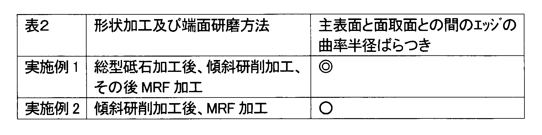
上記表2の結果から、傾斜研削加工の前に総型砥石加工を実施することにより、主表面と面取面との間のエッジ部分の曲率半径のばらつきも小さくなり、形状精度をより改善できることがわかる。これは、総型砥石加工により、傾斜研削加工用砥石の負担が減少して、高精度の加工が長時間継続できたためと考えられる。また、2つの研削加工の傾きが異なることにより、研削条痕が打ち消しあったことも一因と考えられる。
総型砥石加工を行わずに傾斜研削加工する場合、面取りされていない加工前の基板の主表面と端面との間の尖ったエッジが、傾斜研削加工用砥石の表面に直接当たってしまう。そして、それが繰り返されるため、主表面と面取面の境目(主表面と面取面との間のエッジ)の砥石が特にダメージを受けやすい。そのため主表面と面取面との間のエッジ部分の形状がばらつきやすかったと考えられる。
総型砥石加工を行わずに傾斜研削加工する場合、面取りされていない加工前の基板の主表面と端面との間の尖ったエッジが、傾斜研削加工用砥石の表面に直接当たってしまう。そして、それが繰り返されるため、主表面と面取面の境目(主表面と面取面との間のエッジ)の砥石が特にダメージを受けやすい。そのため主表面と面取面との間のエッジ部分の形状がばらつきやすかったと考えられる。
(実施例3)
板厚0.5mmのガラス基板を用いたこと以外は実施例1と同様にして形状加工及び端面研磨工程を実施して、磁気ディスク用ガラス基板を作製した。
端面研磨終了後の基板の外周端面における面取面と側壁面間のエッジ部分の曲率半径ばらつき評価を実施例1と同様にして行い、その結果を表3に示した。
板厚0.5mmのガラス基板を用いたこと以外は実施例1と同様にして形状加工及び端面研磨工程を実施して、磁気ディスク用ガラス基板を作製した。
端面研磨終了後の基板の外周端面における面取面と側壁面間のエッジ部分の曲率半径ばらつき評価を実施例1と同様にして行い、その結果を表3に示した。
(比較例5)
板厚0.5mmのガラス基板を用いたこと以外は比較例3と同様にして形状加工及び端面研磨工程を実施して、磁気ディスク用ガラス基板を作製した。
端面研磨終了後の基板の外周端面における面取面と側壁面間のエッジ部分の曲率半径のばらつき評価を実施例1と同様にして行い、その結果を表3に示した。
また、板厚0.635mmのガラス基板を用いた上記実施例1および比較例3における同様の評価結果についても併せて表3に示した。
板厚0.5mmのガラス基板を用いたこと以外は比較例3と同様にして形状加工及び端面研磨工程を実施して、磁気ディスク用ガラス基板を作製した。
端面研磨終了後の基板の外周端面における面取面と側壁面間のエッジ部分の曲率半径のばらつき評価を実施例1と同様にして行い、その結果を表3に示した。
また、板厚0.635mmのガラス基板を用いた上記実施例1および比較例3における同様の評価結果についても併せて表3に示した。
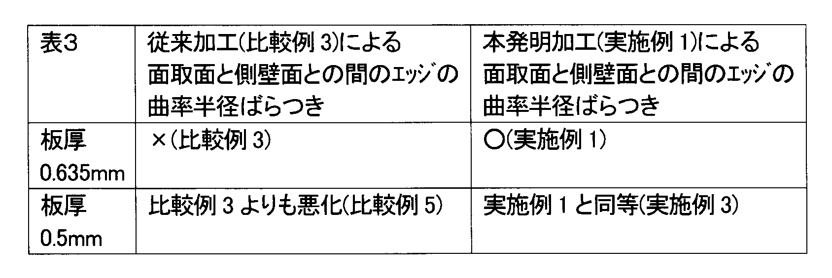
上記表3の結果から、本発明の端面加工処理によれば、薄板でも厚板と同様の品質を確保できるのに対し、従来の加工方法では、薄板になると、ばらつきが悪化してしまい、十分な加工形状精度が得られないことがわかる。
(実施例4)
上記実施例1で得られた磁気ディスク用ガラス基板に以下の成膜工程を施して、垂直磁気記録用磁気ディスクを得た。
すなわち、上記ガラス基板上に、Ti系合金薄膜からなる付着層、CoTaZr合金薄膜からなる軟磁性層、Ru薄膜からなる下地層、CoCrPt合金からなる垂直磁気記録層、カーボン保護層、潤滑層を順次成膜した。保護層は、磁気記録層が磁気ヘッドとの接触によって劣化することを防止するためのもので、水素化カーボンからなり、耐磨耗性が得られる。また、潤滑層は、アルコール変性パーフルオロポリエーテルの液体潤滑剤をディップ法により形成した。
得られた磁気ディスクについて、DFHヘッドを備えたHDDに組み込み、80℃かつ80%RHの高温高湿環境下においてDFH機能を作動させつつ1ヶ月間のロードアンロード耐久性試験を行ったところ、特に障害も無く、良好な結果が得られた。
上記実施例1で得られた磁気ディスク用ガラス基板に以下の成膜工程を施して、垂直磁気記録用磁気ディスクを得た。
すなわち、上記ガラス基板上に、Ti系合金薄膜からなる付着層、CoTaZr合金薄膜からなる軟磁性層、Ru薄膜からなる下地層、CoCrPt合金からなる垂直磁気記録層、カーボン保護層、潤滑層を順次成膜した。保護層は、磁気記録層が磁気ヘッドとの接触によって劣化することを防止するためのもので、水素化カーボンからなり、耐磨耗性が得られる。また、潤滑層は、アルコール変性パーフルオロポリエーテルの液体潤滑剤をディップ法により形成した。
得られた磁気ディスクについて、DFHヘッドを備えたHDDに組み込み、80℃かつ80%RHの高温高湿環境下においてDFH機能を作動させつつ1ヶ月間のロードアンロード耐久性試験を行ったところ、特に障害も無く、良好な結果が得られた。
1 磁気ディスク用ガラス基板
2 外周側端面研削砥石
4 内周側端面研削砥石
3,5 溝
10 ディスク状ガラス基板(ガラスディスク)
11 ガラス基板の主表面
12 ガラス基板の外周側端面
12a 側壁面
12b 面取面
13 ガラス基板の内周側端面
13a 側壁面
13b 面取面
20 端面研磨装置
21,22 磁石
23 スペーサ
24 外装部材
26 磁性スラリの塊
2 外周側端面研削砥石
4 内周側端面研削砥石
3,5 溝
10 ディスク状ガラス基板(ガラスディスク)
11 ガラス基板の主表面
12 ガラス基板の外周側端面
12a 側壁面
12b 面取面
13 ガラス基板の内周側端面
13a 側壁面
13b 面取面
20 端面研磨装置
21,22 磁石
23 スペーサ
24 外装部材
26 磁性スラリの塊
Claims (6)
- ガラス基板の端面を加工する端面加工処理を含む磁気ディスク用ガラス基板の製造方法であって、
前記端面加工処理は、
磁気発生手段を用いて磁力線を形成し、磁性体と研磨砥粒を含む磁性スラリを前記磁力線に保持させることによって前記磁性スラリの塊を形成し、前記ガラス基板の端面を前記磁性スラリの塊と接触させた状態で加工する第1の処理と、
該第1の処理の前加工として行われる、
前記ガラス基板の端面の側壁面と、該ガラス基板の主表面と前記側壁面との間の面取面との両方の面を同時に加工できるように形成された溝形状を有する砥石を用い、該砥石に形成された前記溝形状の溝方向に対して前記ガラス基板を傾けた状態で加工する第2の処理と
を含むことを特徴とする磁気ディスク用ガラス基板の製造方法。 - 前記第2の処理の前に、前記ガラス基板の端面に面取面を形成する処理を行うことを特徴とする請求項1に記載の磁気ディスク用ガラス基板の製造方法。
- 前記面取面を形成する処理と、前記第2の処理とは、基板に対する砥石の溝方向がそれぞれ異なる角度で行われることを特徴とする請求項2に記載の磁気ディスク用ガラス基板の製造方法。
- 前記端面加工処理後の前記ガラス基板の端面の表面粗さがRmaxで0.2μm以下であることを特徴とする請求項1乃至3のいずれかに記載の磁気ディスク用ガラス基板の製造方法。
- 前記端面加工処理に投入する前記ガラス基板の板厚が0.5mm以下であることを特徴とする請求項1乃至4のいずれかに記載の磁気ディスク用ガラス基板の製造方法。
- 請求項1乃至5のいずれかに記載の磁気ディスク用ガラス基板の製造方法により製造された磁気ディスク用ガラス基板上に、少なくとも磁気記録層を形成することを特徴とする磁気ディスクの製造方法。
Priority Applications (3)
| Application Number | Priority Date | Filing Date | Title |
|---|---|---|---|
| JP2014554628A JPWO2014104377A1 (ja) | 2012-12-31 | 2013-12-31 | 磁気ディスク用ガラス基板の製造方法及び磁気ディスクの製造方法 |
| SG11201505032QA SG11201505032QA (en) | 2012-12-31 | 2013-12-31 | Method for manufacturing glass substrates for magnetic disks and method for manufacturing magnetic disks |
| CN201380061388.XA CN104813396A (zh) | 2012-12-31 | 2013-12-31 | 磁盘用玻璃基板的制造方法以及磁盘的制造方法 |
Applications Claiming Priority (2)
| Application Number | Priority Date | Filing Date | Title |
|---|---|---|---|
| JP2012-289283 | 2012-12-31 | ||
| JP2012289283 | 2012-12-31 |
Publications (1)
| Publication Number | Publication Date |
|---|---|
| WO2014104377A1 true WO2014104377A1 (ja) | 2014-07-03 |
Family
ID=51021437
Family Applications (1)
| Application Number | Title | Priority Date | Filing Date |
|---|---|---|---|
| PCT/JP2013/085292 Ceased WO2014104377A1 (ja) | 2012-12-31 | 2013-12-31 | 磁気ディスク用ガラス基板の製造方法及び磁気ディスクの製造方法 |
Country Status (4)
| Country | Link |
|---|---|
| JP (1) | JPWO2014104377A1 (ja) |
| CN (1) | CN104813396A (ja) |
| SG (1) | SG11201505032QA (ja) |
| WO (1) | WO2014104377A1 (ja) |
Citations (3)
| Publication number | Priority date | Publication date | Assignee | Title |
|---|---|---|---|---|
| JP2005050501A (ja) * | 2003-07-15 | 2005-02-24 | Hoya Corp | 磁気ディスク用基板の製造方法、磁気ディスク用基板の製造装置及び磁気ディスクの製造方法 |
| JP2010009723A (ja) * | 2008-06-30 | 2010-01-14 | Hoya Corp | 磁気ディスク用ガラス基板の加工方法、磁気ディスク用ガラス基板の製造方法、および磁気ディスクの製造方法 |
| JP2011108355A (ja) * | 2010-12-20 | 2011-06-02 | Hoya Corp | 磁気記録媒体用ガラス基板及びその製造方法 |
Family Cites Families (2)
| Publication number | Priority date | Publication date | Assignee | Title |
|---|---|---|---|---|
| US7175511B2 (en) * | 2003-07-15 | 2007-02-13 | Hoya Corporation | Method of manufacturing substrate for magnetic disk, apparatus for manufacturing substrate for magnetic disk, and method of manufacturing magnetic disk |
| JP5029777B1 (ja) * | 2011-11-22 | 2012-09-19 | 旭硝子株式会社 | 磁気記録媒体用ガラス基板、および該磁気記録媒体用ガラス基板を用いた磁気記録媒体 |
-
2013
- 2013-12-31 JP JP2014554628A patent/JPWO2014104377A1/ja active Pending
- 2013-12-31 WO PCT/JP2013/085292 patent/WO2014104377A1/ja not_active Ceased
- 2013-12-31 SG SG11201505032QA patent/SG11201505032QA/en unknown
- 2013-12-31 CN CN201380061388.XA patent/CN104813396A/zh active Pending
Patent Citations (3)
| Publication number | Priority date | Publication date | Assignee | Title |
|---|---|---|---|---|
| JP2005050501A (ja) * | 2003-07-15 | 2005-02-24 | Hoya Corp | 磁気ディスク用基板の製造方法、磁気ディスク用基板の製造装置及び磁気ディスクの製造方法 |
| JP2010009723A (ja) * | 2008-06-30 | 2010-01-14 | Hoya Corp | 磁気ディスク用ガラス基板の加工方法、磁気ディスク用ガラス基板の製造方法、および磁気ディスクの製造方法 |
| JP2011108355A (ja) * | 2010-12-20 | 2011-06-02 | Hoya Corp | 磁気記録媒体用ガラス基板及びその製造方法 |
Also Published As
| Publication number | Publication date |
|---|---|
| JPWO2014104377A1 (ja) | 2017-01-19 |
| SG11201505032QA (en) | 2015-07-30 |
| CN104813396A (zh) | 2015-07-29 |
Similar Documents
| Publication | Publication Date | Title |
|---|---|---|
| JP6215770B2 (ja) | 磁気ディスク用ガラス基板、磁気ディスク、磁気ディスク用ガラス基板の製造方法 | |
| US20170169847A1 (en) | Glass substrate for magnetic disk and magnetic disk | |
| JP6490842B2 (ja) | 研削工具、ガラス基板の製造方法、磁気ディスク用ガラス基板の製造方法及び磁気ディスクの製造方法 | |
| WO2015152316A1 (ja) | 磁気ディスク用ガラス基板 | |
| JP6156967B2 (ja) | ガラス基板の製造方法及び磁気ディスクの製造方法、並びにガラス基板の端面研磨装置 | |
| JP2012142044A (ja) | 情報記録媒体用ガラス基板の製造方法および情報記録媒体 | |
| JP5074311B2 (ja) | 磁気ディスク用ガラス基板の加工方法、磁気ディスク用ガラス基板の製造方法、および磁気ディスクの製造方法 | |
| JP2021167062A (ja) | 固定砥粒砥石 | |
| JP2010005772A (ja) | 磁気ディスク用ガラス基板の加工方法、磁気ディスク用ガラス基板の製造方法、及び磁気ディスク用ガラス基板、並びに磁気ディスクの製造方法 | |
| JP2016126808A (ja) | 磁気ディスク用基板の製造方法、及び端面研磨処理装置 | |
| JP5306759B2 (ja) | 磁気ディスク用ガラス基板の製造方法及び磁気ディスクの製造方法 | |
| JPWO2014104377A1 (ja) | 磁気ディスク用ガラス基板の製造方法及び磁気ディスクの製造方法 | |
| JP2015069668A (ja) | 磁気ディスク用ガラス基板の製造方法及び磁気ディスクの製造方法 | |
| JP5639215B2 (ja) | 磁気ディスク用ガラス基板及び磁気ディスク用ガラス基板の製造方法、並びに磁気ディスクの製造方法 | |
| JP5704777B2 (ja) | 磁気ディスク用ガラス基板の製造方法 | |
| JP6193388B2 (ja) | 磁気ディスク用ガラス基板の製造方法、ガラス基板の製造方法及び磁気ディスクの製造方法、並びに固定砥粒砥石 | |
| JP6353524B2 (ja) | 基板の製造方法 |
Legal Events
| Date | Code | Title | Description |
|---|---|---|---|
| 121 | Ep: the epo has been informed by wipo that ep was designated in this application |
Ref document number: 13867760 Country of ref document: EP Kind code of ref document: A1 |
|
| ENP | Entry into the national phase |
Ref document number: 2014554628 Country of ref document: JP Kind code of ref document: A |
|
| NENP | Non-entry into the national phase |
Ref country code: DE |
|
| 122 | Ep: pct application non-entry in european phase |
Ref document number: 13867760 Country of ref document: EP Kind code of ref document: A1 |