WO2014103603A1 - 密閉型電池の製造方法 - Google Patents
密閉型電池の製造方法 Download PDFInfo
- Publication number
- WO2014103603A1 WO2014103603A1 PCT/JP2013/082028 JP2013082028W WO2014103603A1 WO 2014103603 A1 WO2014103603 A1 WO 2014103603A1 JP 2013082028 W JP2013082028 W JP 2013082028W WO 2014103603 A1 WO2014103603 A1 WO 2014103603A1
- Authority
- WO
- WIPO (PCT)
- Prior art keywords
- exterior
- helium
- pressure
- battery
- manufacturing process
- Prior art date
- Legal status (The legal status is an assumption and is not a legal conclusion. Google has not performed a legal analysis and makes no representation as to the accuracy of the status listed.)
- Ceased
Links
Images






Classifications
-
- H—ELECTRICITY
- H01—ELECTRIC ELEMENTS
- H01M—PROCESSES OR MEANS, e.g. BATTERIES, FOR THE DIRECT CONVERSION OF CHEMICAL ENERGY INTO ELECTRICAL ENERGY
- H01M10/00—Secondary cells; Manufacture thereof
- H01M10/42—Methods or arrangements for servicing or maintenance of secondary cells or secondary half-cells
- H01M10/4228—Leak testing of cells or batteries
-
- H—ELECTRICITY
- H01—ELECTRIC ELEMENTS
- H01M—PROCESSES OR MEANS, e.g. BATTERIES, FOR THE DIRECT CONVERSION OF CHEMICAL ENERGY INTO ELECTRICAL ENERGY
- H01M10/00—Secondary cells; Manufacture thereof
- H01M10/05—Accumulators with non-aqueous electrolyte
- H01M10/058—Construction or manufacture
-
- G—PHYSICS
- G01—MEASURING; TESTING
- G01M—TESTING STATIC OR DYNAMIC BALANCE OF MACHINES OR STRUCTURES; TESTING OF STRUCTURES OR APPARATUS, NOT OTHERWISE PROVIDED FOR
- G01M3/00—Investigating fluid-tightness of structures
- G01M3/02—Investigating fluid-tightness of structures by using fluid or vacuum
- G01M3/04—Investigating fluid-tightness of structures by using fluid or vacuum by detecting the presence of fluid at the leakage point
- G01M3/20—Investigating fluid-tightness of structures by using fluid or vacuum by detecting the presence of fluid at the leakage point using special tracer materials, e.g. dye, fluorescent material, radioactive material
-
- G—PHYSICS
- G01—MEASURING; TESTING
- G01M—TESTING STATIC OR DYNAMIC BALANCE OF MACHINES OR STRUCTURES; TESTING OF STRUCTURES OR APPARATUS, NOT OTHERWISE PROVIDED FOR
- G01M3/00—Investigating fluid-tightness of structures
- G01M3/02—Investigating fluid-tightness of structures by using fluid or vacuum
- G01M3/04—Investigating fluid-tightness of structures by using fluid or vacuum by detecting the presence of fluid at the leakage point
- G01M3/20—Investigating fluid-tightness of structures by using fluid or vacuum by detecting the presence of fluid at the leakage point using special tracer materials, e.g. dye, fluorescent material, radioactive material
- G01M3/22—Investigating fluid-tightness of structures by using fluid or vacuum by detecting the presence of fluid at the leakage point using special tracer materials, e.g. dye, fluorescent material, radioactive material for pipes, cables or tubes; for pipe joints or seals; for valves; for welds; for containers, e.g. radiators
- G01M3/226—Investigating fluid-tightness of structures by using fluid or vacuum by detecting the presence of fluid at the leakage point using special tracer materials, e.g. dye, fluorescent material, radioactive material for pipes, cables or tubes; for pipe joints or seals; for valves; for welds; for containers, e.g. radiators for containers, e.g. radiators
- G01M3/229—Investigating fluid-tightness of structures by using fluid or vacuum by detecting the presence of fluid at the leakage point using special tracer materials, e.g. dye, fluorescent material, radioactive material for pipes, cables or tubes; for pipe joints or seals; for valves; for welds; for containers, e.g. radiators for containers, e.g. radiators removably mounted in a test cell
-
- H—ELECTRICITY
- H01—ELECTRIC ELEMENTS
- H01M—PROCESSES OR MEANS, e.g. BATTERIES, FOR THE DIRECT CONVERSION OF CHEMICAL ENERGY INTO ELECTRICAL ENERGY
- H01M10/00—Secondary cells; Manufacture thereof
- H01M10/24—Alkaline accumulators
- H01M10/28—Construction or manufacture
-
- H—ELECTRICITY
- H01—ELECTRIC ELEMENTS
- H01M—PROCESSES OR MEANS, e.g. BATTERIES, FOR THE DIRECT CONVERSION OF CHEMICAL ENERGY INTO ELECTRICAL ENERGY
- H01M50/00—Constructional details or processes of manufacture of the non-active parts of electrochemical cells other than fuel cells, e.g. hybrid cells
- H01M50/10—Primary casings; Jackets or wrappings
- H01M50/183—Sealing members
-
- H—ELECTRICITY
- H01—ELECTRIC ELEMENTS
- H01M—PROCESSES OR MEANS, e.g. BATTERIES, FOR THE DIRECT CONVERSION OF CHEMICAL ENERGY INTO ELECTRICAL ENERGY
- H01M10/00—Secondary cells; Manufacture thereof
- H01M10/04—Construction or manufacture in general
- H01M10/0431—Cells with wound or folded electrodes
-
- Y—GENERAL TAGGING OF NEW TECHNOLOGICAL DEVELOPMENTS; GENERAL TAGGING OF CROSS-SECTIONAL TECHNOLOGIES SPANNING OVER SEVERAL SECTIONS OF THE IPC; TECHNICAL SUBJECTS COVERED BY FORMER USPC CROSS-REFERENCE ART COLLECTIONS [XRACs] AND DIGESTS
- Y02—TECHNOLOGIES OR APPLICATIONS FOR MITIGATION OR ADAPTATION AGAINST CLIMATE CHANGE
- Y02E—REDUCTION OF GREENHOUSE GAS [GHG] EMISSIONS, RELATED TO ENERGY GENERATION, TRANSMISSION OR DISTRIBUTION
- Y02E60/00—Enabling technologies; Technologies with a potential or indirect contribution to GHG emissions mitigation
- Y02E60/10—Energy storage using batteries
-
- Y—GENERAL TAGGING OF NEW TECHNOLOGICAL DEVELOPMENTS; GENERAL TAGGING OF CROSS-SECTIONAL TECHNOLOGIES SPANNING OVER SEVERAL SECTIONS OF THE IPC; TECHNICAL SUBJECTS COVERED BY FORMER USPC CROSS-REFERENCE ART COLLECTIONS [XRACs] AND DIGESTS
- Y02—TECHNOLOGIES OR APPLICATIONS FOR MITIGATION OR ADAPTATION AGAINST CLIMATE CHANGE
- Y02P—CLIMATE CHANGE MITIGATION TECHNOLOGIES IN THE PRODUCTION OR PROCESSING OF GOODS
- Y02P70/00—Climate change mitigation technologies in the production process for final industrial or consumer products
- Y02P70/50—Manufacturing or production processes characterised by the final manufactured product
-
- Y—GENERAL TAGGING OF NEW TECHNOLOGICAL DEVELOPMENTS; GENERAL TAGGING OF CROSS-SECTIONAL TECHNOLOGIES SPANNING OVER SEVERAL SECTIONS OF THE IPC; TECHNICAL SUBJECTS COVERED BY FORMER USPC CROSS-REFERENCE ART COLLECTIONS [XRACs] AND DIGESTS
- Y10—TECHNICAL SUBJECTS COVERED BY FORMER USPC
- Y10T—TECHNICAL SUBJECTS COVERED BY FORMER US CLASSIFICATION
- Y10T29/00—Metal working
- Y10T29/49—Method of mechanical manufacture
- Y10T29/49002—Electrical device making
- Y10T29/49108—Electric battery cell making
- Y10T29/49112—Electric battery cell making including laminating of indefinite length material
Definitions
- the present invention relates to a method for manufacturing a sealed battery in which a leak inspection process for detecting leakage of a detection gas introduced into a battery container is performed.
- Patent Document 1 discloses the following technique. First, the liquid injection nozzle is brought into close contact with the lid of the battery can (battery container), and the liquid injection nozzle is attached to the electrolyte liquid injection port. Next, the electrolytic solution is injected from the injection nozzle, and helium is introduced into the battery can. Then, the injection nozzle is removed from the electrolyte injection port, and the electrolyte injection port is sealed by laser welding means. Finally, the sealed battery can is placed in a leak detection chamber, and a leak inspection process is performed by checking whether helium is leaking from the battery can using a helium leak tester.
- the molecular weight of helium is smaller than the molecular weight of the gas contained in the battery can. Therefore, as shown in FIG. 15, most of the helium introduced from the electrolyte injection port stays in the vicinity of the electrolyte injection port, and the battery is discharged from the electrolyte injection port before the leak inspection process is performed. Leaks out of the can. That is, in the technique disclosed in Patent Document 1, since the amount of helium leakage before the leak inspection process increases, the concentration of helium in the battery can at the time of the leak inspection process cannot be maintained. The helium concentration in the can decreases.
- the amount of helium leaking from the battery can per unit time is confirmed based on the output value of the helium leak tester, and the quality of the leak test is determined.
- the inspection threshold value T1 of the leak inspection process is set in consideration of the case where the helium concentration in the battery can at the time of such a leak inspection process is low.
- the inspection threshold T1 is the output value of the helium leak tester when the battery can in which the helium concentration at the time of the leak test process is low and the helium leak amount per unit time is a predetermined amount L is inspected. Is set.
- the present invention has been made in view of the above situation, and provides a manufacturing method of a sealed battery that can improve an overjudgment rate in a leak inspection process.
- a manufacturing method of a sealed battery according to the present invention is a manufacturing method of a sealed battery in which a leak inspection process for detecting leakage of a detection gas introduced into a battery container is performed, and the battery container is covered to cover the battery container. Temporarily closing the battery container, introducing the detection gas into the battery container, and adjusting at least one of the pressure inside the battery container and the pressure outside the battery container, Adjusting the pressure inside the battery container after the detection gas is introduced to be smaller than the pressure outside the battery container.
- the temporarily sealed battery container is depressurized to a first pressure smaller than the pressure outside the battery container, and the detection gas is contained in the decompressed battery container. It is preferable to pressurize the inside of the battery container to a second pressure smaller than the pressure outside the battery container, and perform the introducing step and the adjusting step simultaneously.
- the overdetermining rate in the leak inspection process can be improved.
- the figure which shows the whole structure of a sealed battery The figure which shows the manufacturing process of a sealed battery.
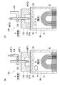
- transduced in the 1st manufacturing process of a sealed battery (a) is a figure which shows the state which is decompressing the exterior, (b) is the state which introduce
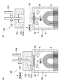
- FIG. It is a figure which shows a mode that an introduction apparatus is removed from a liquid injection hole in the 1st manufacturing process of a sealed battery, (a) is a figure which shows the state before removing an introduction apparatus, (b) removes an introduction apparatus.
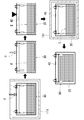
- FIG. It is a figure which shows a mode that a liquid injection hole is sealed, (a) is a figure which shows a mode that a cap is mounted in a liquid injection hole, (b) is a figure which shows a mode that laser welding is carried out.
- the battery 10 is a sealed lithium ion secondary battery.
- the target to which the present invention is applied is not limited to a lithium ion secondary battery, but may be other sealed batteries such as a nickel metal hydride secondary battery.
- a leak inspection process for detecting leakage of the detection gas introduced into the battery container is performed in order to confirm the sealing property of the battery container.
- the battery 10 includes a power generation element 20, an exterior 30, a cap 40, and external terminals 50 and 50.
- the power generation element 20 is obtained by infiltrating an electrolytic solution into an electrode body that is wound in a state where a positive electrode, a negative electrode, and a separator are laminated.
- a chemical reaction occurs in the power generation element 20 (strictly speaking, ions move between the positive electrode and the negative electrode via the electrolytic solution) to generate an electric current.
- the exterior 30 that is a battery container is a substantially rectangular parallelepiped can having a storage portion 31 and a lid portion 32.
- the storage unit 31 is a bottomed rectangular tube-shaped member that is open on one side, and stores the power generation element 20 therein.
- the lid portion 32 is a flat plate-like member having a shape corresponding to the opening surface of the storage portion 31, and is joined to the storage portion 31 in a state where the opening surface of the storage portion 31 is closed. As will be described later, in the lid portion 32, a liquid injection hole 33 for injecting an electrolytic solution is opened between locations where the external terminals 50 and 50 are inserted.
- the liquid injection hole 33 is a hole having a substantially circular shape in a plan view in which the inner diameter is different between the outside and the inside of the lid portion 32.
- the liquid injection hole 33 is formed such that the inner diameter of the upper part (upper part in FIG. 1) is larger than the inner diameter of the lower part (lower part in FIG. 1).
- the battery is configured as a prismatic battery having an exterior formed in a bottomed rectangular tube shape.
- the present invention is not limited to this.
- the battery is formed in a bottomed cylindrical shape. It is also possible to configure as a cylindrical battery having an exterior.
- the cap 40 is for sealing the liquid injection hole 33.
- the cap 40 is formed in substantially the same shape as the upper part of the liquid injection hole 33.
- the cap 40 is fitted into the upper part of the liquid injection hole 33 so as to block the lower part of the liquid injection hole 33, and is joined to the lid part 32 by laser welding of the outer peripheral edge part.
- the external terminals 50 and 50 are arranged in a state in which some of them protrude from the outer surface of the lid portion 32 upward (outward) of the battery 10.
- the external terminals 50 and 50 are electrically connected to the positive electrode and the negative electrode of the power generation element 20 through current collecting terminals 51 and 51, respectively.
- the external terminals 50 and 50 are fixed in an insulated state with respect to the lid portion 32 with the insulating members 52 and 53 interposed therebetween by fitting the fixing members 34 on the outer peripheral surface portions, respectively.
- the external terminals 50 and 50 and the current collecting terminals 51 and 51 function as an energization path for taking out the electric power stored in the power generation element 20 to the outside or taking in electric power from the outside into the power generation element 20.
- the current collecting terminals 51 and 51 are connected to the positive electrode and the negative electrode of the power generation element 20, respectively.
- As the material of the current collecting terminals 51 and 51 for example, aluminum can be used on the positive electrode side and copper on the negative electrode side.
- the external terminals 50 and 50 are thread-rolled at portions projecting outward from the battery 10 to form bolt portions.
- members such as a bus bar and a connection terminal of the external device are fastened and fixed to the external terminals 50 and 50 using the bolt portion.
- a fastening torque is applied to the external terminals 50 and 50, and an external force is applied in the axial direction by screw fastening.
- a mixture (a positive electrode mixture and a negative electrode mixture) on the surface of a current collector (a positive electrode current collector and a negative electrode current collector) using a coating machine such as a die coder .
- a coating machine such as a die coder
- Dry the mixture After applying a mixture (a positive electrode mixture and a negative electrode mixture) on the surface of a current collector (a positive electrode current collector and a negative electrode current collector) using a coating machine such as a die coder , Dry the mixture. Then, a mixture layer (a positive electrode mixture layer and a negative electrode mixture layer) is formed on the surface of the current collector by pressing the mixture on the surface of the current collector. In this way, a positive electrode and a negative electrode are produced.
- the positive electrode and the negative electrode manufactured through such a process and a separator are wound in a stacked state to manufacture an electrode body. Then, the external terminals 50 and 50 and the current collecting terminals 51 and 51 integrated with the lid portion 32 of the exterior 30 are connected to the electrode body, and the electrode body is accommodated in the accommodating portion 31 of the exterior 30. Then, the storage part 31 and the cover part 32 of the exterior 30 are joined by welding and sealed.
- the electrolytic solution E is injected from the injection hole 33 (see arrow E shown in FIG. 2).
- the exterior 30 is housed in the chamber 111, and a predetermined liquid injection unit is set in the exterior 30 to evacuate the chamber 111. Thereafter, air is introduced into the chamber 111 to return the chamber 111 to atmospheric pressure.
- the electrolytic solution E is injected into the exterior 30 using the differential pressure at this time.
- the exterior 30 After pouring the electrolytic solution E into the exterior 30, the exterior 30 is moved outside the chamber 111 and helium H is introduced into the exterior 30 (see arrow H shown in FIG. 2).
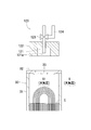
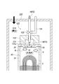
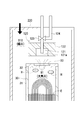
- helium H is introduced using an introduction device 120 as shown in FIG.
- the introduction device 120 includes an enclosure nozzle 121, a seal member 122, a valve 123, and the like.
- the sealing nozzle 121 is disposed above the liquid injection hole 33, and an injection port 121a is formed at the lower end.
- a valve 123 is connected to the middle part of the sealing nozzle 121 in the vertical direction.
- the sealing nozzle 121 is connected to a predetermined decompression pump via a valve 123, a pipe 124, and the like. That is, in the introduction device 120, a pressure reducing path P1 is formed as a path from the sealing nozzle 121 toward the pressure reducing pump (see FIG. 5A).
- the sealing nozzle 121 is connected to a predetermined helium supply source via a valve 123 or the like. That is, in the introduction device 120, a supply path P2 is formed as a path from the helium supply source to the sealing nozzle 121 (see FIG. 5B).
- the seal member 122 has a shape in which a through-hole penetrating along the vertical direction is formed on the bottom surface (upper surface) of the substantially bottomed cylindrical member.
- the sealing nozzle 121 is inserted through the through hole of the seal member 122.
- the injection port 121 a of the sealing nozzle 121 is disposed inside the seal member 122.
- the valve 123 closes one of the decompression path P1 and the supply path P2 and opens the other. That is, the introduction device 120 switches the path communicating with the sealing nozzle 121 to either the pressure reducing path P1 or the supply path P2 by controlling the valve 123.
- the introduction device 120 configured in this way is installed in a facility such that the external space S of the exterior 30 is at atmospheric pressure, for example. Therefore, before the introduction of helium H, both the internal space S1 and the external space S of the exterior 30 are at atmospheric pressure.
- the introduction device 120 when introducing helium H into the exterior 30, the introduction device 120 is moved closer to the exterior 30 and the seal member 122 is pressed against the lid portion 32 (see the arrow shown in FIG. 4). Thereby, the introducing device 120 seals the liquid injection hole 33. Further, the seal member 122 is in close contact with the outer peripheral surface of the enclosing nozzle 121 in the middle of the upper and lower sides.
- the exterior 30 by covering the exterior 30 (the liquid injection hole 33), the internal space S1 of the exterior 30 is blocked from the external space S, and the exterior 30 is temporarily sealed. That is, the exterior 30 is closed.
- the decompression path P1 is opened (the decompression path P1 and the sealing nozzle 121 are communicated), and the decompression pump is operated to operate the exterior 30.
- the air A inside is discharged to the outside. That is, the inside of the exterior 30 is depressurized (see the internal space S1 shown in FIG. 5A).
- the introduction device 120 is provided with a pressure gauge capable of measuring the pressure in the exterior 30 as described above.
- the introduction device 120 depressurizes the exterior 30 to the first pressure while confirming the pressure in the exterior 30 with the pressure gauge.
- the introduction device 120 opens the supply path P2 (the supply path P2 and the sealing nozzle 121 communicate with each other), and supplies helium H to the sealing nozzle 121 from the helium supply source. Then, helium H is injected from the injection port 121 a of the sealing nozzle 121.
- an introduction process of introducing helium H into the temporarily sealed outer package 30 is performed.
- the introduction device 120 is removed from the injection hole 33 to release the temporarily sealed state of the exterior 30, and the injection hole 33 is removed by the cap 40. Seal.
- the cap 40 is fitted into the upper part of the liquid injection hole 33 so as to block the lower part of the liquid injection hole 33.
- a laser is irradiated along the outer edge part of the cap 40 with a laser welding machine, and the liquid injection hole 33 is sealed (refer the black triangle shown in FIG. 2).
- the device for sealing the liquid injection hole 33 is installed in the facility such that the external space S of the exterior 30 is at atmospheric pressure, like the introduction device 120.
- the exterior 30 is housed in the chamber 131 and the inside of the chamber 131 is evacuated. Thereafter, the amount of helium H leaking from the exterior 30 per unit time is confirmed using a commercially available helium leak tester.
- a leak inspection process for detecting leakage of helium H is performed. That is, helium H is employed as the detection gas in the first manufacturing process.
- the battery 10 After performing the leak inspection process, the battery 10 is initially charged, the voltage is inspected, and the like. As described above, in the first manufacturing process, the sealed battery 10 is manufactured.
- the molecular weight of helium H is smaller than the molecular weight of the gas contained in the exterior 30. Therefore, as shown in FIG. 6A, helium H introduced into the exterior 30 stays in the vicinity of the liquid injection hole 33.
- the external space S of the exterior 30 is at atmospheric pressure as in the present embodiment, when helium H is introduced into the exterior 30 and the interior of the exterior 30 is returned to atmospheric pressure, the helium H is introduced from the injection hole 33. Many leaks.
- the outer packaging reduced in pressure to the first pressure by injecting helium H while confirming the pressure fluctuation in the outer packaging 30.
- 30 is pressurized to a second pressure lower than atmospheric pressure. That is, the introduction device 120 introduces helium H into the exterior 30 by an amount smaller than the amount of air A discharged from the exterior 30. That is, helium H in an amount corresponding to the pressure fluctuation in the exterior 30 (difference between the first pressure and the second pressure) is introduced into the exterior 30 (see arrows A and H shown in FIG. 5).
- the inside of the exterior 30 after introducing helium H is brought into a negative pressure state, and a pressure difference is generated between the exterior 30 and the exterior 30 (the internal space S1 and the external space shown in FIG. 6A). S).
- helium H that is about to leak from the liquid injection hole 33 due to the difference in molecular weight can be pushed into the internal space S1 of the exterior 30 by the air flow. That is, helium H can be retained in the exterior 30 even after the temporarily sealed state of the exterior 30 is released.
- the leak inspection process can be performed with a small amount of helium H. Therefore, in the first manufacturing process, helium H can be used efficiently, so the helium utilization rate can be improved. That is, in the first manufacturing process, the cost required for leak inspection can be reduced.
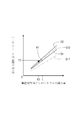
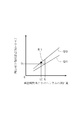
- the output value of the helium leak tester becomes smaller than the test threshold value T2
- the output value of the helium leak tester is checked.
- T2 the threshold value
- the output value of the helium leak tester is low overall because the amount of helium H leaking from the exterior 30 per unit time decreases when the helium concentration in the exterior 30 at the time of the leak inspection process is low as in the graph G11. It becomes.
- the helium concentration in the exterior 30 is high as shown in the graph G1.
- a leak inspection process can be performed. That is, in the first manufacturing process, the output value of the helium leak tester can be increased as a whole compared to the prior art by reducing the amount of helium leak before the leak test process (see FIG. 8). (See arrow shown).
- the inspection threshold value T2 can be set based on the output value of the helium leak tester when the helium concentration in the exterior 30 is high.
- the inspection threshold value T2 at the time of the leakage inspection process can be increased as compared with the conventional technique, so that the leakage inspection can be performed with high sensitivity.
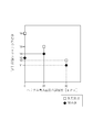
- a small amount of helium H determined to some extent before the leak inspection process leaks out by reducing the amount of helium leak before the leak inspection process. That is, the variation in the helium concentration in the exterior 30 during the leak inspection process can be reduced.
- the output value of the helium leak inspection device is the inspection threshold value. It can suppress exceeding T2 (refer the point shown in FIG. 9). That is, in the first manufacturing process, the overdetermining rate in the leak inspection process can be improved (see the regions R1 and R11 that are overdetermined shown in FIGS. 9 and 16).
- an adjustment process is performed in which the pressure in the exterior 30 after the introduction of helium H is made smaller than the pressure outside the exterior 30.
- the inside of the temporarily sealed exterior 30 is reduced to a first pressure smaller than the pressure outside the exterior 30, and the detection gas is introduced into the decompressed exterior 30,
- the inside of the exterior 30 is pressurized to a second pressure smaller than the pressure outside the exterior 30, and the introduction process and the adjustment process are performed simultaneously.
- the amount of helium leakage before the leak inspection process can be reduced only by adjusting the amount of helium H introduced. That is, the adjustment process for improving the overjudgment rate can be simplified.
- the method of introducing helium H is not limited to the above method. That is, the exterior 30 may be housed in a chamber, and after the chamber is depressurized, helium H may be introduced into the chamber to pressurize the chamber. In this case, the pressure in the chamber is adjusted so that the pressure in the chamber becomes smaller than the pressure outside the chamber after the introduction of helium. Then, the exterior 30 is moved outside the chamber, and the liquid injection hole 33 is sealed. That is, in the first manufacturing process, when helium H is introduced, the entire exterior 30 is covered, or only a portion where the external space S and the internal space S1 of the exterior 30 communicate with each other is partially covered. Therefore, the exterior 30 may be temporarily sealed.
- the first manufacturing process was performed to produce the test pieces of the first and second examples (see FIGS. 6 and 7).
- the test pieces of the first embodiment and the second embodiment differ mainly in the degree of decompression in the exterior 30 immediately after the introduction of helium H.
- the test piece of the first example has helium H in the exterior 30 that has been decompressed to the first pressure so that the degree of decompression in the exterior 30 immediately after the introduction of helium is X1 (kPa). It is a test piece manufactured by introducing.
- the helium concentration (hereinafter referred to as “initial concentration”) in the exterior 30 immediately after the introduction of helium H is Y5 (%).
- the test piece of the second embodiment is manufactured by introducing helium H into the exterior 30 that has been decompressed to the first pressure so that the decompression degree X2 (kPa) is higher than the decompression degree X1 of the first embodiment. Test piece. That is, since the test piece of the second embodiment has a smaller amount of helium H introduced in the exterior 30 than in the first embodiment, the initial concentration is Y2 (%) lower than the initial concentration Y5 of the first embodiment. ). Further, the test piece of the second embodiment has a larger pressure difference between the inside and outside of the exterior 30 after the introduction of helium than the test piece of the first embodiment.
- the pressure is reduced to the first pressure so that the degree of decompression in the exterior 30 immediately after the introduction of helium becomes 0 (kPa).
- Helium H was introduced into the outer package 30 to produce a test piece of a comparative example. That is, the test piece of the comparative example is a test piece manufactured by sealing the liquid injection hole 33 in a state where there is no pressure difference inside and outside the exterior 30 after introducing helium.
- the test piece of the comparative example is higher than the initial concentrations Y5 and Y2 of the test pieces of the first and second embodiments because helium H in a larger amount than that of the first embodiment is introduced into the exterior 30. Y6 (%).
- the introduction device 120 was removed from the injection hole 33, and the injection hole 33 was sealed after a lapse of a certain time. A hole was made in the exterior 30 and the head of the helium concentration measuring device was quickly pressed into the hole to measure the helium concentration after sealing the liquid injection hole 33.
- the test piece of the comparative example was Y3 (%) in which the helium concentration after sealing the injection hole 33 was greatly reduced from the initial concentration Y6. This is because a large amount of helium H leaked from the liquid injection hole 33 after helium was introduced.
- the test piece of the first example was Y4 (%) which was slightly reduced from the initial density Y5. That is, the test piece of the first example was able to improve the degree of decrease in the helium concentration Y4 after sealing the liquid injection hole 33 with respect to the initial concentration Y5 as compared with the test piece of the comparative example.
- the test piece of the first example has the helium concentration Y4 after sealing the liquid injection hole 33 sealed in the liquid injection hole 33 of the comparative example, even though the initial concentration Y5 was lower than the initial concentration Y6 of the comparative example.
- the helium concentration after stopping was higher than Y3. That is, the utilization rate of helium H was higher in the test piece of the first example than in the comparative example.
- test piece of the second example was able to improve the degree of decrease in the helium concentration Y1 (%) after sealing the injection hole 33 with respect to the initial concentration Y2, as compared with the test piece of the first example.
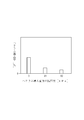
- Each graph shown in FIG. 11 shows the helium leakage rate (the ratio of the helium concentration after sealing the injection hole 33 to the initial concentration) of each test piece before the leak inspection process.
- the helium leakage rate before the leak inspection process decreases as the degree of decompression in the exterior 30 immediately after the introduction of helium increases.
- the second manufacturing process is different from the first manufacturing process in the method for making the pressure in the exterior 30 smaller than the pressure outside the exterior 30. For this reason, below, the method for making the pressure in the exterior 30 smaller than the pressure outside the exterior 30 is demonstrated in detail.
- the exterior 30 is accommodated in the chamber 220.
- the introduction device 120 in the first manufacturing process is installed. Before the introduction of helium H into the exterior 30, the inside of the chamber 220 and the interior of the exterior 30 are at atmospheric pressure.
- helium H is introduced into the exterior 30 installed in such a chamber 220. That is, in the second manufacturing process, the internal space S ⁇ b> 10 of the chamber 220 is an external space of the exterior 30. In the second manufacturing process, after the inside of the exterior 30 is depressurized to a predetermined pressure, an amount of helium H corresponding to the predetermined pressure is introduced into the exterior 30 to return the interior of the exterior 30 to atmospheric pressure (FIG. 13). Internal space S1 shown in FIG.
- the introduction device 120 is removed from the liquid injection hole 33.
- an air flow from the liquid injection hole 33 into the exterior 30 can be generated by the differential pressure between the exterior space 30 and the internal spaces S1 and S10 of the chamber 220 (see arrows shown in FIG. 14). Therefore, in the second manufacturing process, it is possible to reduce the amount of helium leakage before the leak inspection process.
- the pressure inside the exterior 30 is made smaller than the pressure outside the exterior 30 by pressurizing the exterior of the exterior 30, that is, the inside of the chamber 220, instead of reducing the pressure inside the exterior 30.
- the helium concentration in the exterior 30 during the leak inspection process can be maintained in a high state from the introduction of helium H to the leak inspection process. Therefore, in the second manufacturing process, the overdetermining rate in the leak inspection process can be improved (see FIG. 9).
- the method for making the pressure in the exterior 30 smaller than the pressure outside the exterior 30 is not limited to the method in the first manufacturing process and the second manufacturing process.
- the inside of the exterior 30 may be depressurized and the outside of the exterior 30 may be pressurized.
- the exterior 30 is accommodated in the chamber 220 shown in FIG. 12, the inside of the exterior 30 is decompressed in the same manner as in the first manufacturing process, and the inside of the chamber 220 is added in the same manner as in the second manufacturing process. Press.
- the pressure difference inside and outside the exterior 30 can be further increased, the amount of helium leakage before the leak inspection process can be effectively reduced.
- the inside of the exterior 30 may be pressurized to a third pressure that is about several kPa higher than the atmospheric pressure, and the outside of the exterior 30 may be pressurized to a fourth pressure that is about several tens of kPa higher than the third pressure.
- the exterior 30 is accommodated in the chamber 220 shown in FIG. 12, the inside of the exterior 30 after helium introduction is pressurized by increasing the amount of helium H introduced, and the chamber 220 is processed in the same manner as in the second manufacturing process. Pressurize the inside.
- the outside of the exterior 30 may be decompressed to a fifth pressure that is about several kPa lower than the atmospheric pressure, and the inside of the exterior 30 may be decompressed to a sixth pressure that is about several tens of kPa smaller than the fifth pressure.
- the exterior 30 is accommodated in the chamber 220 shown in FIG. 12, and the interior of the exterior 30 is decompressed in the same manner as in the first manufacturing process, and the air in the chamber 220 is discharged to decompress the interior of the chamber 220. To do.
- At least one of the pressure inside the exterior 30 and the pressure outside the exterior 30 may be adjusted.
- the pressure inside the exterior 30 is more preferably smaller than the pressure outside the exterior 30 to such an extent that the amount of helium leakage before the leak inspection process can be reduced to some extent (for example, about several tens of kPa).
- the detection gas is not limited to helium in the first manufacturing process and the second manufacturing process, but it is preferable to employ helium. This is because helium can be used to prevent battery performance from being affected, and leakage from fine holes with a small molecular diameter can be detected. It is because it can obtain. Further, when helium is introduced, a mixed gas in which helium and a gas other than helium are mixed may be introduced.
- the present invention can be used in a manufacturing method of a sealed battery in which a leak inspection process for detecting leakage of a detection gas introduced into a battery container is performed.
Landscapes
- Chemical & Material Sciences (AREA)
- Chemical Kinetics & Catalysis (AREA)
- Electrochemistry (AREA)
- General Chemical & Material Sciences (AREA)
- Engineering & Computer Science (AREA)
- Manufacturing & Machinery (AREA)
- Physics & Mathematics (AREA)
- General Physics & Mathematics (AREA)
- Secondary Cells (AREA)
- Examining Or Testing Airtightness (AREA)
Abstract
Description
まず、注液ノズルを電池缶(電池容器)の蓋体に密着させて注液ノズルを電解液注液口に装着する。
次に、注液ノズルより電解液を注液するとともに、電池缶内にヘリウムを導入する。
そして、電解液注液口より注液ノズルを取り外し、レーザ溶接手段によって電解液注液口を封口する。
最後に、封口した電池缶を漏洩検出チャンバーに設置し、ヘリウムリーク検査器を用いて電池缶からヘリウムが漏れているかどうか確認することでリーク検査工程を行う。
すなわち、特許文献1に開示される技術では、リーク検査工程前のヘリウム漏出量が多くなってしまうため、リーク検査工程時の電池缶内のヘリウムの濃度を維持できず、リーク検査工程時の電池缶内のヘリウム濃度が低下してしまう。
図16に示すように、リーク検査工程の検査閾値T1は、このようなリーク検査工程時の電池缶内のヘリウム濃度が低い場合を考慮して設定される。すなわち、検査閾値T1は、リーク検査工程時のヘリウム濃度が低く、かつ、単位時間当たりのヘリウムの漏れ量が所定量Lとなる電池缶を検査したときの、ヘリウムリーク検査器の出力値等が設定される。
従って、単位時間当たりのヘリウムの漏れ量L0が所定量Lよりもやや少ない電池缶を検査したときに、当該電池缶内におけるヘリウム濃度のばらつきの影響によってヘリウムの漏れ量が所定量Lである電池缶よりも高くなっていると、ヘリウムリーク検査器の出力値は、比較的高い割合で検査閾値T1を超えてしまう可能性がある(図16に示す点およびグラフG12参照)。
つまり、特許文献1に開示される技術では、リーク検査工程における過判定率が悪化してしまう可能性があった。
電池10の第一製造工程においては、電池容器の密閉性を確認するために、電池容器内に導入された検知ガスの漏れを検知するリーク検査工程が行われる。
集電端子51・51は、それぞれ発電要素20の正極および負極と接続されている。集電端子51・51の材料としては、例えば、正極側にアルミニウム、負極側に銅を採用することができる。
それらの部材を締結固定する際、外部端子50・50には締結トルクがかかるとともに、ねじ締結によって軸方向へ外力が付与される。このため、外部端子50・50の材料としては、鉄等の高強度材料を採用することが好ましい。
そして、集電体の表面上の合剤に対してプレス加工を施すことで、集電体の表面に合剤層(正極合剤層および負極合剤層)を形成する。
こうして、正極および負極が作製される。
このとき、例えば、外装30をチャンバー111内に収納するとともに、所定の注液ユニットを外装30にセットして、チャンバー111内を真空引きする。その後、チャンバー111内に大気を導入してチャンバー111内を大気圧に戻す。前記第一製造工程においては、このときの差圧を利用して、電解液Eを外装30に注液する。
封入ノズル121は、シール部材122の貫通孔に挿通される。封入ノズル121の噴射口121aは、シール部材122の内側に配置される。
従って、ヘリウムHを導入する前の時点において、外装30の内部空間S1および外部空間Sは、ともに大気圧となっている。
すなわち、図5(b)に示すように、導入装置120は、供給経路P2を開放し(供給経路P2と封入ノズル121とを連通し)、前記ヘリウム供給源より封入ノズル121にヘリウムHを供給し、封入ノズル121の噴射口121aよりヘリウムHを噴射する。
このとき、キャップ40を、注液孔33の下部を塞ぐように注液孔33の上部に嵌め込む。そして、レーザー溶接機によってキャップ40の外縁部に沿ってレーザーを照射し、注液孔33を封止する(図2に示す黒塗りの三角形参照)。
このような注液孔33を封止するための装置は、導入装置120と同様に、外装30の外部空間Sが大気圧となるような設備内に設置される。
以上のように、前記第一製造工程においては、密閉型の電池10を製造する。
本実施形態のように外装30の外部空間Sが大気圧である場合、ヘリウムHを外装30内に導入して外装30内を大気圧に戻した場合には、ヘリウムHが注液孔33より多く漏出してしまう可能性がある。
すなわち、導入装置120は、外装30内の空気Aを排出した量よりも少ない量だけヘリウムHを外装30内に導入する。つまり、外装30内の圧力変動(第一の圧力と第二の圧力との差)に対応する量のヘリウムHを、外装30内に導入する(図5に示す矢印A・H参照)。
これにより、ヘリウムHを導入した後の外装30内を陰圧状態にして、外装30内と外装30外との間に圧力差を発生させる(図6(a)に示す内部空間S1および外部空間S参照)。
図7(a)に示すように、このような気流が発生している間、または、その後に、注液孔33にキャップ40を嵌め込み、図7(b)に示すように、レーザ溶接機によるレーザ照射によって注液孔33を封止する(図7に示す外部空間S、内部空間S1、および矢印参照)。
つまり、外装30の一時的な密閉状態を解除した後も、ヘリウムHを外装30内に留めることができる。
ヘリウムリーク検査器の出力値は、グラフG11のようにリーク検査工程時の外装30内のヘリウム濃度が低い場合、単位時間当たりに外装30から漏れるヘリウムHの量が減るため、全体的に低い値となる。
すなわち、前記第一製造工程においては、リーク検査工程前のヘリウム漏出量を低減することで、従来技術と比較して、ヘリウムリーク検査器の出力値を全体的に引き上げることができる(図8に示す矢印参照)。
すなわち、リーク検査工程時の外装30内のヘリウム濃度のばらつきを低減できる。
つまり、前記第一製造工程においては、リーク検査工程における過判定率を改善できる(図9および図16に示す過判定となる領域R1・R11参照)。
これにより、ヘリウムHの導入量を調整するだけで、リーク検査工程前のヘリウム漏出量を低減できる。つまり、過判定率を改善するための調整工程を簡素化できる。
この場合、ヘリウム導入後に前記チャンバー内の圧力が前記チャンバー外の圧力よりも小さくなるように、前記チャンバー内の圧力を調整する。そして、前記チャンバー外に外装30を移動させ、注液孔33を封止する。
すなわち、前記第一製造工程においては、ヘリウムHを導入するときに、外装30全体を覆う、または、外装30の外部空間Sと内部空間S1とが連通している箇所だけを部分的に覆うことで、外装30を一時的に密閉すればよい。
第一実施例および第二実施例のテストピースは、主にヘリウムHを導入した直後の外装30内の減圧度が異なる。
第一実施例のテストピースは、ヘリウムHを導入した直後の外装30内のヘリウム濃度(以下、「初期濃度」と表記する)がY5(%)である。
すなわち、第二実施例のテストピースは、外装30内に第一実施例よりも少ない量のヘリウムHが導入されているため、初期濃度が第一実施例の初期濃度Y5よりも低いY2(%)である。また、第二実施例のテストピースは、ヘリウム導入後の外装30内外の圧力差が第一実施例のテストピースよりも大きい。
すなわち、比較例のテストピースは、ヘリウム導入後の外装30内および外装30外に圧力差がない状態で、注液孔33を封止して作製されたテストピースである。
比較例のテストピースは、外装30内に第一実施例よりも多い量のヘリウムHが導入されているため、第一実施例および第二実施例のテストピースの初期濃度Y5・Y2よりも高いY6(%)である。
これは、ヘリウム導入後に注液孔33からヘリウムHが多く漏出したことによるものである。
また、第一実施例のテストピースは、初期濃度Y5が比較例の初期濃度Y6よりも低かったにも関わらず、注液孔33封止後のヘリウム濃度Y4が比較例の注液孔33封止後のヘリウム濃度Y3よりも高くなった。
つまり、第一実施例のテストピースは、比較例よりもヘリウムHの利用率が高くなった。
図11に示すように、リーク検査工程前のヘリウム漏出率は、ヘリウム導入直後の外装30内の減圧度が大きくなるにつれて低下している。
つまり、前記第一製造工程においては、リーク検査工程における過判定率を改善できることが明らかとなった。
このため、以下では、外装30内の圧力を外装30外の圧力よりも小さくするための手法について詳細に説明する。
外装30内にヘリウムHを導入する前の段階において、チャンバー220内および外装30内は大気圧となっている。
前記第二製造工程においては、外装30内を所定の圧力まで減圧した後で、外装30内に所定の圧力に対応する量のヘリウムHを導入し、外装30内を大気圧に戻す(図13に示す内部空間S1参照)。
これにより、チャンバー220内を陽圧状態にする(図13に示す内部空間S10参照)。
このとき、外装30およびチャンバー220の内部空間S1・S10の差圧によって、注液孔33から外装30内に向かう気流を発生させることができる(図14に示す矢印参照)。従って、前記第二製造工程においては、リーク検査工程前のヘリウム漏出量を低減できる。
従って、前記第二製造工程においては、リーク検査工程における過判定率を改善できる(図9参照)。
この場合、例えば、図12に示すチャンバー220内に外装30を収納し、前記第一製造工程と同じ要領で外装30内を減圧するとともに、前記第二製造工程と同じ要領でチャンバー220内を加圧する。
これにより、外装30内外の圧力差をより大きくできるため、リーク検査工程前のヘリウム漏出量を効果的に低減できる。
この場合、例えば、図12に示すチャンバー220内に外装30を収納し、ヘリウムHの導入量を増やしてヘリウム導入後の外装30内を加圧するとともに、前記第二製造工程と同じ要領でチャンバー220内を加圧する。
この場合、例えば、図12に示すチャンバー220内に外装30を収納し、前記第一製造工程と同じ要領で外装30内を減圧するとともに、チャンバー220内の空気を排出してチャンバー220内を減圧する。
また、ヘリウムを導入するときに、ヘリウムとヘリウム以外のガスとを混合した混合ガスを導入しても構わない。
30 外装(電池容器)
H ヘリウム(検知ガス)
Claims (2)
- 電池容器内に導入された検知ガスの漏れを検知するリーク検査工程が行われる密閉型電池の製造方法であって、
前記電池容器を覆うことで前記電池容器を一時的に密閉して、前記電池容器内に前記検知ガスを導入する導入工程と、
前記一時的に密閉した電池容器内の圧力および電池容器外の圧力の少なくとも一方を調整し、前記検知ガス導入後の前記電池容器内の圧力を前記電池容器外の圧力よりも小さくする調整工程と、を含む、
密閉型電池の製造方法。 - 前記一時的に密閉した電池容器内を、前記電池容器外の圧力よりも小さい第一の圧力まで減圧し、
前記減圧した電池容器内に前記検知ガスを導入することで、前記電池容器外の圧力よりも小さい第二の圧力まで前記電池容器内を加圧して、
前記導入工程および前記調整工程を同時に行う、
請求項1に記載の密閉型電池の製造方法。
Priority Applications (3)
| Application Number | Priority Date | Filing Date | Title |
|---|---|---|---|
| US14/655,215 US9780414B2 (en) | 2012-12-26 | 2013-11-28 | Method for manufacturing sealed battery |
| KR1020157019990A KR101726337B1 (ko) | 2012-12-26 | 2013-11-28 | 밀폐형 전지의 제조 방법 |
| CN201380067977.9A CN104885285B (zh) | 2012-12-26 | 2013-11-28 | 密闭型电池的制造方法 |
Applications Claiming Priority (2)
| Application Number | Priority Date | Filing Date | Title |
|---|---|---|---|
| JP2012283406A JP5751246B2 (ja) | 2012-12-26 | 2012-12-26 | 密閉型電池の製造方法 |
| JP2012-283406 | 2012-12-26 |
Publications (1)
| Publication Number | Publication Date |
|---|---|
| WO2014103603A1 true WO2014103603A1 (ja) | 2014-07-03 |
Family
ID=51020697
Family Applications (1)
| Application Number | Title | Priority Date | Filing Date |
|---|---|---|---|
| PCT/JP2013/082028 Ceased WO2014103603A1 (ja) | 2012-12-26 | 2013-11-28 | 密閉型電池の製造方法 |
Country Status (5)
| Country | Link |
|---|---|
| US (1) | US9780414B2 (ja) |
| JP (1) | JP5751246B2 (ja) |
| KR (1) | KR101726337B1 (ja) |
| CN (1) | CN104885285B (ja) |
| WO (1) | WO2014103603A1 (ja) |
Cited By (2)
| Publication number | Priority date | Publication date | Assignee | Title |
|---|---|---|---|---|
| CN105390733A (zh) * | 2015-11-25 | 2016-03-09 | 铜陵市金利电子有限公司 | 用于锂电池封口器的下压装置 |
| CN109148984A (zh) * | 2018-09-30 | 2019-01-04 | 苏州安唯科工业自动化有限公司 | 一种全自动汽车动力电池泄漏检测设备 |
Families Citing this family (9)
| Publication number | Priority date | Publication date | Assignee | Title |
|---|---|---|---|---|
| WO2014010024A1 (ja) * | 2012-07-09 | 2014-01-16 | トヨタ自動車株式会社 | 電池製造方法 |
| JP6635287B2 (ja) * | 2015-08-28 | 2020-01-22 | 株式会社豊田自動織機 | 電池用容器の封止装置および電池用容器の封止方法 |
| JP6534600B2 (ja) * | 2015-10-30 | 2019-06-26 | 株式会社豊田自動織機 | 蓄電装置の製造方法 |
| EP3456824A4 (en) | 2016-05-13 | 2020-03-11 | The University of Tokyo | THERAPEUTIC AGENT FOR OBESITY-RELATED ILLNESS BY INHIBITORY ACTION OF METABOLIC HEPATIC SECRETION REGULATOR |
| CN106898829B (zh) * | 2017-03-02 | 2023-11-21 | 华霆(合肥)动力技术有限公司 | 电池系统失稳检测设备及方法 |
| KR102150759B1 (ko) | 2017-10-26 | 2020-09-01 | 주식회사 엘지화학 | 파우치형 전지의 압력변화 측정을 위한 부품 및 이를 이용한 파우치형 전지의 압력변화 측정 방법 |
| CN111504561A (zh) * | 2020-03-26 | 2020-08-07 | 合肥国轩高科动力能源有限公司 | 一种锂离子电池气密性的检测方法 |
| KR102915136B1 (ko) * | 2025-04-21 | 2026-01-20 | 한국진공주식회사 | 배터리 리크 검사 장비 |
| KR102889734B1 (ko) * | 2025-04-21 | 2025-11-21 | 한국진공주식회사 | 배터리 리크 검사 장비 |
Citations (2)
| Publication number | Priority date | Publication date | Assignee | Title |
|---|---|---|---|---|
| JPH0521089A (ja) * | 1991-07-16 | 1993-01-29 | Matsushita Electric Ind Co Ltd | 鉛蓄電池の気密検査方法とその装置 |
| JP2002117901A (ja) * | 2000-10-05 | 2002-04-19 | Nec Mobile Energy Kk | 密閉型電池およびその製造方法 |
Family Cites Families (6)
| Publication number | Priority date | Publication date | Assignee | Title |
|---|---|---|---|---|
| JP4010477B2 (ja) * | 1999-10-29 | 2007-11-21 | Necトーキン株式会社 | 容器内への液体の注液装置および注液方法 |
| JP4671462B2 (ja) * | 2000-02-22 | 2011-04-20 | パナソニック株式会社 | ニッケル水素二次電池の気密検査方法 |
| US6593026B1 (en) * | 2000-10-25 | 2003-07-15 | Nec Tokin Tochigi, Ltd. | Sealed battery and method for manufacturing sealed battery |
| CA2844044A1 (en) | 2011-08-19 | 2013-02-28 | Jernkontoret | A process for recovering metals and an electrolytic apparatus for performing the process |
| WO2014010024A1 (ja) | 2012-07-09 | 2014-01-16 | トヨタ自動車株式会社 | 電池製造方法 |
| JP5790604B2 (ja) | 2012-08-07 | 2015-10-07 | トヨタ自動車株式会社 | 密閉型電池の製造方法 |
-
2012
- 2012-12-26 JP JP2012283406A patent/JP5751246B2/ja active Active
-
2013
- 2013-11-28 CN CN201380067977.9A patent/CN104885285B/zh active Active
- 2013-11-28 US US14/655,215 patent/US9780414B2/en active Active
- 2013-11-28 WO PCT/JP2013/082028 patent/WO2014103603A1/ja not_active Ceased
- 2013-11-28 KR KR1020157019990A patent/KR101726337B1/ko active Active
Patent Citations (2)
| Publication number | Priority date | Publication date | Assignee | Title |
|---|---|---|---|---|
| JPH0521089A (ja) * | 1991-07-16 | 1993-01-29 | Matsushita Electric Ind Co Ltd | 鉛蓄電池の気密検査方法とその装置 |
| JP2002117901A (ja) * | 2000-10-05 | 2002-04-19 | Nec Mobile Energy Kk | 密閉型電池およびその製造方法 |
Cited By (2)
| Publication number | Priority date | Publication date | Assignee | Title |
|---|---|---|---|---|
| CN105390733A (zh) * | 2015-11-25 | 2016-03-09 | 铜陵市金利电子有限公司 | 用于锂电池封口器的下压装置 |
| CN109148984A (zh) * | 2018-09-30 | 2019-01-04 | 苏州安唯科工业自动化有限公司 | 一种全自动汽车动力电池泄漏检测设备 |
Also Published As
| Publication number | Publication date |
|---|---|
| JP2014127352A (ja) | 2014-07-07 |
| CN104885285B (zh) | 2017-05-24 |
| KR101726337B1 (ko) | 2017-04-12 |
| JP5751246B2 (ja) | 2015-07-22 |
| KR20150098673A (ko) | 2015-08-28 |
| US20150349386A1 (en) | 2015-12-03 |
| US9780414B2 (en) | 2017-10-03 |
| CN104885285A (zh) | 2015-09-02 |
Similar Documents
| Publication | Publication Date | Title |
|---|---|---|
| WO2014103603A1 (ja) | 密閉型電池の製造方法 | |
| KR101672146B1 (ko) | 밀폐형 전지의 제조 방법 | |
| KR101691754B1 (ko) | 전지 제조 방법 | |
| JP4843947B2 (ja) | 密閉型電池の製造方法、及び、気密検査装置 | |
| US10396342B2 (en) | Method for manufacturing secondary cell having a wound body effectively impregnated with electrolytic solution | |
| JP5747937B2 (ja) | 密閉型電池の製造方法 | |
| JP2009026569A (ja) | 密閉型電池の気密検査方法及び密閉型電池 | |
| WO2014003175A1 (ja) | 密閉型電池の製造方法 | |
| JP2012104276A (ja) | 二次電池の検査方法 | |
| JP5742863B2 (ja) | 密閉型電池の製造方法 | |
| JP2021025975A (ja) | 電池の漏液検査方法 | |
| JP5958756B2 (ja) | 電流遮断弁のリーク検査方法 | |
| KR102264674B1 (ko) | 진공을 이용한 전해액 주액 방법 | |
| JP6057132B2 (ja) | 密閉型電池の製造方法 |
Legal Events
| Date | Code | Title | Description |
|---|---|---|---|
| DPE2 | Request for preliminary examination filed before expiration of 19th month from priority date (pct application filed from 20040101) | ||
| 121 | Ep: the epo has been informed by wipo that ep was designated in this application |
Ref document number: 13868445 Country of ref document: EP Kind code of ref document: A1 |
|
| WWE | Wipo information: entry into national phase |
Ref document number: 14655215 Country of ref document: US |
|
| NENP | Non-entry into the national phase |
Ref country code: DE |
|
| ENP | Entry into the national phase |
Ref document number: 20157019990 Country of ref document: KR Kind code of ref document: A |
|
| 122 | Ep: pct application non-entry in european phase |
Ref document number: 13868445 Country of ref document: EP Kind code of ref document: A1 |