WO2014102865A1 - Device and method for producing electrolyzed liquid - Google Patents
Device and method for producing electrolyzed liquid Download PDFInfo
- Publication number
- WO2014102865A1 WO2014102865A1 PCT/JP2012/008363 JP2012008363W WO2014102865A1 WO 2014102865 A1 WO2014102865 A1 WO 2014102865A1 JP 2012008363 W JP2012008363 W JP 2012008363W WO 2014102865 A1 WO2014102865 A1 WO 2014102865A1
- Authority
- WO
- WIPO (PCT)
- Prior art keywords
- container
- liquid
- anode
- pipe
- electrolyzed
- Prior art date
Links
Images


Classifications
-
- C—CHEMISTRY; METALLURGY
- C25—ELECTROLYTIC OR ELECTROPHORETIC PROCESSES; APPARATUS THEREFOR
- C25B—ELECTROLYTIC OR ELECTROPHORETIC PROCESSES FOR THE PRODUCTION OF COMPOUNDS OR NON-METALS; APPARATUS THEREFOR
- C25B15/00—Operating or servicing cells
- C25B15/08—Supplying or removing reactants or electrolytes; Regeneration of electrolytes
-
- C—CHEMISTRY; METALLURGY
- C02—TREATMENT OF WATER, WASTE WATER, SEWAGE, OR SLUDGE
- C02F—TREATMENT OF WATER, WASTE WATER, SEWAGE, OR SLUDGE
- C02F1/00—Treatment of water, waste water, or sewage
- C02F1/46—Treatment of water, waste water, or sewage by electrochemical methods
- C02F1/461—Treatment of water, waste water, or sewage by electrochemical methods by electrolysis
- C02F1/467—Treatment of water, waste water, or sewage by electrochemical methods by electrolysis by electrochemical disinfection; by electrooxydation or by electroreduction
- C02F1/4672—Treatment of water, waste water, or sewage by electrochemical methods by electrolysis by electrochemical disinfection; by electrooxydation or by electroreduction by electrooxydation
- C02F1/4674—Treatment of water, waste water, or sewage by electrochemical methods by electrolysis by electrochemical disinfection; by electrooxydation or by electroreduction by electrooxydation with halogen or compound of halogens, e.g. chlorine, bromine
-
- C—CHEMISTRY; METALLURGY
- C25—ELECTROLYTIC OR ELECTROPHORETIC PROCESSES; APPARATUS THEREFOR
- C25B—ELECTROLYTIC OR ELECTROPHORETIC PROCESSES FOR THE PRODUCTION OF COMPOUNDS OR NON-METALS; APPARATUS THEREFOR
- C25B1/00—Electrolytic production of inorganic compounds or non-metals
- C25B1/01—Products
- C25B1/24—Halogens or compounds thereof
- C25B1/26—Chlorine; Compounds thereof
-
- C—CHEMISTRY; METALLURGY
- C25—ELECTROLYTIC OR ELECTROPHORETIC PROCESSES; APPARATUS THEREFOR
- C25B—ELECTROLYTIC OR ELECTROPHORETIC PROCESSES FOR THE PRODUCTION OF COMPOUNDS OR NON-METALS; APPARATUS THEREFOR
- C25B9/00—Cells or assemblies of cells; Constructional parts of cells; Assemblies of constructional parts, e.g. electrode-diaphragm assemblies; Process-related cell features
- C25B9/17—Cells comprising dimensionally-stable non-movable electrodes; Assemblies of constructional parts thereof
-
- C—CHEMISTRY; METALLURGY
- C02—TREATMENT OF WATER, WASTE WATER, SEWAGE, OR SLUDGE
- C02F—TREATMENT OF WATER, WASTE WATER, SEWAGE, OR SLUDGE
- C02F1/00—Treatment of water, waste water, or sewage
- C02F1/46—Treatment of water, waste water, or sewage by electrochemical methods
- C02F1/461—Treatment of water, waste water, or sewage by electrochemical methods by electrolysis
- C02F1/46104—Devices therefor; Their operating or servicing
- C02F1/4618—Devices therefor; Their operating or servicing for producing "ionised" acidic or basic water
-
- C—CHEMISTRY; METALLURGY
- C02—TREATMENT OF WATER, WASTE WATER, SEWAGE, OR SLUDGE
- C02F—TREATMENT OF WATER, WASTE WATER, SEWAGE, OR SLUDGE
- C02F1/00—Treatment of water, waste water, or sewage
- C02F1/46—Treatment of water, waste water, or sewage by electrochemical methods
- C02F1/461—Treatment of water, waste water, or sewage by electrochemical methods by electrolysis
- C02F1/46104—Devices therefor; Their operating or servicing
- C02F1/46109—Electrodes
- C02F2001/46133—Electrodes characterised by the material
-
- C—CHEMISTRY; METALLURGY
- C02—TREATMENT OF WATER, WASTE WATER, SEWAGE, OR SLUDGE
- C02F—TREATMENT OF WATER, WASTE WATER, SEWAGE, OR SLUDGE
- C02F1/00—Treatment of water, waste water, or sewage
- C02F1/46—Treatment of water, waste water, or sewage by electrochemical methods
- C02F1/461—Treatment of water, waste water, or sewage by electrochemical methods by electrolysis
- C02F1/46104—Devices therefor; Their operating or servicing
- C02F1/46109—Electrodes
- C02F2001/46152—Electrodes characterised by the shape or form
- C02F2001/46171—Cylindrical or tubular shaped
-
- C—CHEMISTRY; METALLURGY
- C02—TREATMENT OF WATER, WASTE WATER, SEWAGE, OR SLUDGE
- C02F—TREATMENT OF WATER, WASTE WATER, SEWAGE, OR SLUDGE
- C02F2209/00—Controlling or monitoring parameters in water treatment
- C02F2209/005—Processes using a programmable logic controller [PLC]
-
- C—CHEMISTRY; METALLURGY
- C02—TREATMENT OF WATER, WASTE WATER, SEWAGE, OR SLUDGE
- C02F—TREATMENT OF WATER, WASTE WATER, SEWAGE, OR SLUDGE
- C02F2209/00—Controlling or monitoring parameters in water treatment
- C02F2209/005—Processes using a programmable logic controller [PLC]
- C02F2209/008—Processes using a programmable logic controller [PLC] comprising telecommunication features, e.g. modems or antennas
-
- C—CHEMISTRY; METALLURGY
- C02—TREATMENT OF WATER, WASTE WATER, SEWAGE, OR SLUDGE
- C02F—TREATMENT OF WATER, WASTE WATER, SEWAGE, OR SLUDGE
- C02F2209/00—Controlling or monitoring parameters in water treatment
- C02F2209/06—Controlling or monitoring parameters in water treatment pH
-
- Y—GENERAL TAGGING OF NEW TECHNOLOGICAL DEVELOPMENTS; GENERAL TAGGING OF CROSS-SECTIONAL TECHNOLOGIES SPANNING OVER SEVERAL SECTIONS OF THE IPC; TECHNICAL SUBJECTS COVERED BY FORMER USPC CROSS-REFERENCE ART COLLECTIONS [XRACs] AND DIGESTS
- Y10—TECHNICAL SUBJECTS COVERED BY FORMER USPC
- Y10T—TECHNICAL SUBJECTS COVERED BY FORMER US CLASSIFICATION
- Y10T29/00—Metal working
- Y10T29/49—Method of mechanical manufacture
- Y10T29/49002—Electrical device making
Definitions
- the embodiment of the electrolyzer device disclosed herein comprises a container configured to receive liquid to be electrolyzed; an anode arranged in the container and operatively connected to a power supply; a cathode arranged in the container so as to surround at least a portion of the anode and operatively connected to the power supply; a first pipe in liquid connection with the container, the first pipe including an intake port arranged in the vicinity of the cathode relative to the anode; and a second pipe in liquid connection with the container.
- the rod 4 may be operatively connected to the power supply 5 so that the rod 4 may serve as an anode of the electrolyzer device 1.
- the other end of the conductive rod 4 may be spaced away from a bottom of the container 3.
- water (H 2 O) may be electrolyzed to generate hydrogen gas (H 2 ) and hydroxide ions (OH - ). Further, sodium ions (Na + ) may react with the hydroxide ions (OH - ) to reversibly produce sodium hydroxide (NaOH). Consequently, strongly alkaline electrolyzed water may be produced.
- the electrolyzed water having a pH in the range from strongly acidic to neutral may be introduced into the intake port 71 from an opening 71k thereof when the on-off valve 73 is opened.
- the intake port 71 may also function as a second outlet port in the present disclosure.
- an intake port may be arranged so as to extend along the sidewall of the container in the transverse section thereof, the strongly alkaline electrolyzed water can be discharged from the intake port. This may allow the pH of the electrolyzed water in the container 3 to be adjusted by discharging an amount of the strongly alkaline electrolyzed water.
Landscapes
- Chemical & Material Sciences (AREA)
- Organic Chemistry (AREA)
- Chemical Kinetics & Catalysis (AREA)
- Electrochemistry (AREA)
- Engineering & Computer Science (AREA)
- Materials Engineering (AREA)
- Metallurgy (AREA)
- Inorganic Chemistry (AREA)
- General Chemical & Material Sciences (AREA)
- Life Sciences & Earth Sciences (AREA)
- Hydrology & Water Resources (AREA)
- Environmental & Geological Engineering (AREA)
- Water Supply & Treatment (AREA)
- Water Treatment By Electricity Or Magnetism (AREA)
Abstract
An electrolyzer device comprises a container configured to receive liquid to be electrolyzed; an anode arranged in the container and operatively connected to a power supply; a cathode arranged in the container so as to surround at least a portion of the anode and operatively connected to the power supply; a first pipe in liquid connection with the container, the first pipe including an intake port arranged in the vicinity of the cathode relative to the anode; and a second pipe in liquid connection with the container.
Description
The present disclosure relates to a device and method for producing electrolyzed liquid or electrolytes.
Electrolysis is well known as being a method of separating an ionic substance, that is either molten or dissolved in a suitable solution, by way of a chemical reaction. A device for achieving electrolysis may require certain components, such as an electrolyte containing an ionic substance, a pair of electrodes (i.e., an anode and a cathode), and a direct electric current supply to drive chemical reactions at the electrodes. As one example, an electrolyzer device may include a container that retains an electrolyte such as a salt solution (i.e., water solving sodium chloride serving as an electrolysis aid), as well as an anode and a cathode arranged in the container. In the electrolysis process, the salt solution is electrolyzed by chemical reactions, resulting in the production of strongly acidic electrolyzed water (SAEW) at the anode and strongly alkaline electrolyzed water at the cathode. The resulting SAEW contains an available chlorine (AC) such as hypochlorous acid (HClO), which is known to have a strong sterilizing/cleansing action, and which thus enables the killing of various microorganisms such as viruses and bacteria. Further, by way of blending the SAEW and the strongly alkaline electrolyzed water, electrolyzed water having a pH in the physiologically neutral range (i.e., weakly acidic, slightly acidic, neutral) can be obtained. Water having such a neutral pH may be suitable for biological use.
The embodiment of the electrolyzer device disclosed herein comprises a container configured to receive liquid to be electrolyzed; an anode arranged in the container and operatively connected to a power supply; a cathode arranged in the container so as to surround at least a portion of the anode and operatively connected to the power supply; a first pipe in liquid connection with the container, the first pipe including an intake port arranged in the vicinity of the cathode relative to the anode; and a second pipe in liquid connection with the container.
In the electrolyzer device thus constituted, the strongly acidic electrolyzed liquid is produced at the anode and the strongly alkaline electrolyzed liquid is produced at the cathode arranged in the container so as to surround at least a portion of the cathode. The strongly alkaline electrolyzed liquid produced at the cathode is discharged from the intake port of the first pipe, which is arranged in the vicinity of the cathode relative to the anode, to the outside of the container thorough the first pipe. As a result, the pH of the electrolyzed liquid remaining in the container is inclined to be low (toward the acidic side), whereby the electrolyzed liquid having a pH in the range between strong acidity and neutrality is produced in the container. The electrolyzed liquid thus obtained can be easily extracted from the container with the second pipe.
In the following detailed description, reference is made to the accompanying drawings, which form a part hereof. In the drawings, similar symbols typically identify similar components, unless context dictates otherwise. Further, the drawings are intended to be explanatory and may not be drawn to scale. The illustrative embodiments described in the detailed description, drawings, and claims are not meant to be limiting. Other embodiments may be utilized, and other changes may be made, without departing from the spirit or scope of the subject matter presented herein. It will be readily understood that the aspects of the present disclosure, as generally described herein, and illustrated in the Figures, can be arranged, substituted, combined, separated, and designed in a wide variety of different configurations, all of which are explicitly contemplated herein.
The present disclosure describes techniques, devices, apparatuses, systems, and methods for electrolysis including, but not limited to: electrolyzing a liquid in a container by providing energy to a cathode and an anode, arranged in a the container, such energy being necessary to cause chemical reactions at the cathode and the anode; obtaining alkaline electrolyzed liquid in the vicinity of the cathode relative to the anode; and obtaining acidic or substantially-neutral electrolyzed liquid in the vicinity of the anode relative to the cathode.
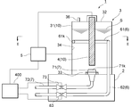
FIGs. 1 and 2 are schematic sectional views showing a non-limiting example of an electrolyzer device arranged in accordance with the present disclosure. The electrolyzer device may be used to produce electrolyzed water having a pH in the physiologically neutral range (i.e., weakly acidic, slightly acidic, neutral) by way of electrolyzing a dilute salt solution S, which may be referred to herein as "liquid to be electrolyzed".
It should be noted that the term "electrolyzed water" as used herein, is a general term for aqueous solutions obtained by providing direct electric current to, for example, tap water and a dilute salt solution in a container through a cathode and an anode. Various types of electrolyzed water may be produced depending on the difference in the electrolyzer and electrolysis system. For example, such electrolyzed waters may be defined in accordance with pH and/or available chlorine (AC) concentration.
Generally, the strongly acidic electrolyzed water (SAEW) may have a large positive "oxidation-reduction potential" (ORP) value, which may represent strong oxidizing power. Further, "available chlorine (AC) concentration" may refer to the total concentration of chlorine contained in free chlorine and binding-form chlorine, and may represent the concentration of chlorine effectively involved in sterilization.
Referring now to FIGs. 1 and 2, an electrolyzer device 1 may include a container 3 arranged on a support base 2. The container 3 may be an electrolysis cell in, for example, a cylindrical shape having a sidewall 31. The sidewall 31 may be made of a conductive material, such as , but not limited to, SUS. The sidewall 31 of the container 3 may be operatively connected to a DC power supply 5 so that the sidewall 31 serves as a cathode in the electrolyzer device 1. As a non-limiting example, the entire container 3 may be made of a conductive material. Alternatively, instead of the sidewall 31 being made of a conductive material, the container 3 may include an electrode plate arranged along an inner surface 34 of the container 3. The container 3 may further include a top cover 32 to seal content in the container 3. The top cover 32 may be provided with an inlet port 36 to supply a dilute salt solution S into the container 3.
Although not shown in FIGs. 1 and 2, the electrolyzer device 1 may further include a solution supply system configured to supply the salt solution S to the container 3. The solution supply system may include a reservoir configured to store the salt solution S therein. The salt solution S may be supplied through a pipe operatively connecting the reservoir and the container 3. The pipe may include a flow-rate controller configured to adjust a flow rate of the salt solution S. As a non-limiting example, the solution supply system may supply raw materials of the salt solution S (i.e., water and salt) separately to the container 3, resulting in mixed liquid in the container 3. As another non-limiting example, the raw materials may be mixed within the pipe between the reservoir and the container 3.
Further, the electrolyzer device 1 may include a rod 4 arranged in the container 3 and extending in a vertical direction (i.e., a depth direction). The shape and size in a transverse section of the rod 4 may be freely selected. As a non-limiting example, the rod 4 may be made of a conductive material such as, but not limited to, graphite. As a further non-limiting example, one end of the rod 4 may be attached to the top cover 32 of the container 3 to be positioned at substantially the center of the container 3 in the transverse section thereof. By way of this arrangement, the rod 4 may be surrounded by the sidewall 31 of the container 3 in the traverse section so that they face each other along the entire perimeter thereof, forming a pair of electrodes 10. The rod 4 may be operatively connected to the power supply 5 so that the rod 4 may serve as an anode of the electrolyzer device 1. As a further non-limiting example, the other end of the conductive rod 4 may be spaced away from a bottom of the container 3.
Further, a first pipe 6 and a second pipe 7 may be arranged to be in liquid connection with the container 3. Specifically, the first pipe 6 may include an intake port 61, which extends substantially along the internal surface 34 of the container 3 in the traverse section, and a delivery pipe 62 connected to one end of the intake port 61. As a non-limiting example, the intake port 61 may travel substantially halfway across the internal surface 34. As a result of this, the intake port 61 of the first pipe 6 may be arranged in the vicinity of the sidewall 31 of the container 3 (i.e., the cathode) relative to the rod 4 (i.e., the anode). Further, as shown in FIG. 1, a vertical position of the intake port 61 may be at substantially half of the height of the container 3, but such a vertical position of the intake port 61 should not be limited.
FIG. 3 is a schematic sectional view showing another example of an electrolyzer device arranged in accordance with the present disclosure. Referring to FIG. 3, as another non-limiting example, the intake port 61 may be positioned at a lower portion of the container 3. Alternatively, the intake port 61 may be positioned at an upper portion of the container 3.
The delivery pipe 62 may include a portion extending downward along the internal surface 34 of the container 3. The delivery pipe 62 may pass through the support base 2 so as to deliver the salt solution S electrolyzed from the intake port 61 to the outside of the electrolyzer device 1. The first pipe 6 may include an on-off valve 63, such as, but not limited to, a solenoid valve, to control a flow of the salt solution S electrolyzed.
The second pipe 7 may also include an intake port 71 arranged in the vicinity of a bottom portion 33 of the container 3, and a delivery pipe 72 connected to the intake port 71. As a non-limiting example, the intake port 71 may be arranged at substantially the center of the bottom of the container 3. The delivery pipe 72 of the second pipe 7 may also pass through the support base 2 to deliver liquid from the intake port 71 to the outside of the electrolyzer device 1. The pipe 72 may also be an on-off valve 73 to control a flow of the liquid.
The electrolyzer device 1 may be comprehensively controlled by a computing device. FIG. 4 is a block diagram showing an example computing device 400 that is arranged for the electrolyzer device 1 in accordance with the present disclosure. In a very basic configuration 402, computing device 400 typically includes one or more processors 404 and a system memory 406. A memory bus 408 may be used for communicating between processor 404 and system memory 406.
Depending on the desired configuration, processor 404 may be of any type including but not limited to a microprocessor, a microcontroller, a digital signal processor (DSP), or any combination thereof. Processor 404 may include one more levels of caching, such as a level one cache 410 and a level two cache 412, a processor core 414, and registers 416. An example processor core 414 may include an arithmetic logic unit (ALU), a floating point unit (FPU), a digital signal processing core (DSP Core), or any combination thereof. An example memory controller 418 may also be used with processor 404, or in some implementations memory controller 418 may be an internal part of processor 404.
Depending on the desired configuration, system memory 406 may be of any type including but not limited to volatile memory (such as RAM), non-volatile memory (such as ROM, flash memory, etc.) or any combination thereof. System memory 406 may include an operating system 420, one or more applications 422, and program data 424. Application 422 may include a control program 426 that is arranged to the electrolyzer device 1. The control program 426 may select, for example, a power of the power supply 5 and an amount of electrolyzed water to be discharged thorough the pipe 6. Program data 424 may include control data 428 that may be useful for the electrolyzer device 1 as is described herein. In some embodiments, application 422 may be arranged to operate with program data 424 on operating system 420 such that the selected power is adjusted and maintained. This described basic configuration 402 is illustrated in FIG. 4 by those components within the inner dashed line.
The network communication link may be one example of a communication media. Communication media may typically be embodied by computer readable instructions, data structures, program modules, or other data in a modulated data signal, such as a carrier wave or other transport mechanism, and may include any information delivery media. A "modulated data signal" may be a signal that has one or more of its characteristics set or changed in such a manner as to encode information in the signal. By way of example, and not limitation, communication media may include wired media such as a wired network or direct-wired connection, and wireless media such as acoustic, radio frequency (RF), microwave, infrared (IR) and other wireless media. The term computer readable media as used herein may include both storage media and communication media.
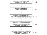
FIG. 5 is a flow chart showing an example of a method for manufacturing the electrolyzer device 1 in accordance with the present disclosure. Referring to FIG. 5, in an operation 510, the container 3 to receive a solution such as the salt solution S may be provided on the support base 2. The container 3 may be configured to include a conductive portion being made of, but not limited to being made of, SUS at, at least, a side wall thereof. The side wall may correspond to the sidewall 31, which serves as the cathode, as discussed above. As another non-limiting example, a plate electrode may be arranged in a container made of an insulating material on a side wall thereof. In an operation 520, a conductive rod being made of, but not limited to being made of, graphite, may be arranged in the container 3 to extend in the vertical direction (i.e., the depth direction) of the container. As a further non-limiting example, the conductive rod may be positioned at substantially the center of the container 3 so as to be spaced away from the bottom of the container 3.
In an operation 530, the rod 4 may be operatively connected to a positive electrode of the DC power supply 5, whereas the sidewall 31 of the container 3 may be operatively connected to a negative electrode of the DC power supply 5. In an operation 540, the first pipe 6 having the intake port 61 may be arranged so as to be in liquid connection with the container 3. In this operation, the intake port 61 may be positioned in the vicinity of the side wall 31 of the container 3 relative to the rod 4. In an operation 550, the second pipe 7 may be arranged so as to be in liquid connection with the container 3.
FIG. 6 is a flow chart showing an example of a method for producing electrolyzed liquid that is arranged for the electrolyzer device 1 in accordance with the present disclosure. The method may be performed under control of the computing device 400 of the electrolyzer device 1.
Referring to FIG. 6, in an operation 610, the salt solution S may be supplied into the container 3 from the inlet port 36 so that the solution S can be in contact with the pair of electrodes 10 (i.e., the rod 4 and the sidewall 31).
When power (i.e., DC current) is applied to the pair of electrodes 10 by the DC power supply 5, in an operation 620, electrons may be provided therefrom, and thus the electrons may be interchanged between the ions in the salt solution S and the pair of electrodes 10 of the container 3. By this way, the following chemical reactions may occur so as to electrolyze the salt solution S.
(Reactions at the Anode)
H2O --> 1/2 O2 + 2H+ +2e-
2Cl- --> Cl2 + 2e-
Cl2(aq) + H2O <--> HCl + HClO
H2O --> 1/2 O2 + 2H+ +2e-
2Cl- --> Cl2 + 2e-
Cl2(aq) + H2O <--> HCl + HClO
As shown above, at the rod 4, water (H2O) may be electrolyzed into hydrogen ions (H+) and oxygen gas (O2). Further, chlorine gas (Cl2) may be generated from chlorine ions (Cl-). Furthermore, the chlorine gas (Cl2) may be reacted with water (H2O) to reversibly produce hydrochloric acid (HCl) and hypochlorous acid (HClO). Consequently, strongly acidic electrolyzed water (SAEW) may be produced. Note that, in the above formula, the symbol "<-->" means that the reaction is reversible (the same shall apply hereinafter).
(Reactions at the Cathode)
2H2O + 2e- --> H2 + 2OH-
Na++OH- <--> NaOH
2H2O + 2e- --> H2 + 2OH-
Na++OH- <--> NaOH
On the other hand, at the side wall 31 of the container 3, water (H2O) may be electrolyzed to generate hydrogen gas (H2) and hydroxide ions (OH-). Further, sodium ions (Na+) may react with the hydroxide ions (OH-) to reversibly produce sodium hydroxide (NaOH). Consequently, strongly alkaline electrolyzed water may be produced.
As the above reactions proceed, the amount of strongly acidic electrolyzed water (SAEW) may gradually be increased around the rod 4, which may be arranged at substantially the center of the container 3. On the other hand, in an operation 630, the strongly alkaline electrolyzed water produced in the vicinity of the internal wall 34 of the container 3 may be introduced into the intake port 61 from an opening 61k thereof and discharged to the outside of the container 3 through the delivery pipe 62 when the on-off valve 63 is opened. In this way, the intake port 61 may also function as a first outlet port in the present disclosure. In an example, such discharged strongly alkaline electrolyzed water may be used for an intended purpose.
As a result of this, the strongly acidic electrolyzed water (SAEW) which may include hydrochloric acid (HCl) and hypochlorous acid (HClO) / hydrogen ions (H+) may be diffused from the vicinity of the rod 4, so that the pH of electrolyzed water remaining in the container 3 may become more acidic. While, sodium hydroxide (NaOH) / hydroxide ions (OH-) which may remain in the vicinity of the internal wall 34 of the container 3 and may be contained in the newly generated SAEW may be neutralized by hydrochloric acid (HCl) and hypochlorous acid (HClO) / hydrogen ions (H+). Consequently, the electrolyzed water having a pH in the range from strongly acidic to neutral, i.e., electrolyzed water having a sterilizing action and a pH in the physiologically neutral range suitable for biological use may be generated and gradually increased in the container 3.
In an operation 640, the electrolyzed water having a pH in the range from strongly acidic to neutral may be introduced into the intake port 71 from an opening 71k thereof when the on-off valve 73 is opened. By way of this, such electrolyzed water may easily be extracted from the container 3 through the delivery pipe 72. In this way, the intake port 71 may also function as a second outlet port in the present disclosure.
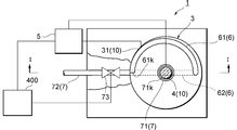
FIG. 7 is a schematic sectional view showing an example of a sterilizing liquid production device using the electrolyzer device 1 arranged in accordance with the present disclosure. Referring to FIG. 7, a sterilizing liquid production device 100 may be configured to include the electrolyzer device 1. Specifically, the sterilizing liquid production device 100 may include a housing 40, which may determine to a large extent an exterior of the sterilizing liquid production device 100. The housing 40 may accommodate the container 3 of the electrolyzer device 1 therein. The housing 40 may also accommodate the computing device 400 therein. Alternatively, the computing device 400 may be an external device operatively connected to a communication interface provided in the electrolyzer device 1.
The sterilizing liquid production device 100 may also include a display device 8 of which a screen may be arranged at a portion of the housing 40. The sterilizing liquid production device 100 may be configured so that electric power can be supplied from an external, commercial source, and may thus include a cable 51 having a plug to be inserted into an electric outlet, and an AC-DC converter 52 to convert AC current from the commercial source into DC current for the sterilizing liquid production device 100. The delivery pipe 72 of the second pipe 7 may be connected to a joint pipe 74 which may have characteristics of flexibility.
The sterilizing liquid production device 100 as discussed above may electrolyze the salt solution S to produce the strongly acidic electrolyzed water (SAEW) 91. The produced SAEW 91 may be discharged to the outside through the first pipe 6, while the electrolyzed water having a sterilizing action and a pH in the physiologically neutral range suitable for biological use may be extracted.
As a result of the various configurations described in detail above, the present disclosure may include one or more of the following advantages, some of which have been discussed above. For example, according to the present disclosure, electrolyzed water, which may have a sterilizing effect and a pH in the physiologically neutral range suitable for biological use may easily and effectively be produced and obtained by a simple configuration of an electrolyzer device and a simple method using the same. Specifically, electrolyzed water, which may have a pH in the range between strong acidity and neutrality, may be easily obtained from a container of the electrolyzer device. Further, the electrolyzer device may allow the pH of the extracted acidic or substantially-neutral electrolyzed water to easily be selected by controlling an amount of the strongly alkaline electrolyzed water. Thus, the electrolyzer device may allow the produced electrolyzed water to be used effectively, thereby avoiding unnecessary disposal thereof.
More specifically, a configuration of a conventional electrolyzer device may be complex, as it may use a pair of parallel-plate electrodes and a diaphragm wall arranged between the electrodes. Further, such a conventional device may require complicated work to obtain the electrolyzed water within a physiologically neutral pH range.
Further, the electrolyzer device in the present disclosure may employ the sidewall of the container as the cathode, thereby allowing the configuration of the electrolyzer device 1 to be simplified even further. Moreover, a graphite rod can be employed as the anode, and the costs of the electrolyzer device may thereby be reduced.
Moreover, as the graphite rod may be arranged as the anode in the vicinity of a center of the container, the anode may be surrounded by the cathode at a constant distance, and thereby the strongly alkaline electrolyzed water may be obtained at the vicinity of the sidewall of the container .
Specifically, since an intake port may be arranged so as to extend along the sidewall of the container in the transverse section thereof, the strongly alkaline electrolyzed water can be discharged from the intake port. This may allow the pH of the electrolyzed water in the container 3 to be adjusted by discharging an amount of the strongly alkaline electrolyzed water.
(Experimental Example 1)
Using an experimental device, which implemented theelectrolyzer device 1, a dilute salt solution S was electrolyzed. The values of the pH and available chlorine (AC) concentration of the electrolyzed water extracted from the second pipe 7 were measured, by changing the time in which power was applied to the pair of electrodes 10 (electrolysis time) and the amount of the strongly alkaline electrolyzed water discharged. It should be noted that a pH meter was used for measuring the pH and absorptiometry was used for measuring the AC concentration. Of the obtained measurement results, the levels of the discharged strongly alkaline electrolyzed water, pH and available chlorine (AC) concentration of the extracted electrolyzed water at 30 minutes after the start of the electrolysis are listed in TABLE 1.
Using an experimental device, which implemented the

One skilled in the art will appreciate that, for this and other processes and methods disclosed herein, the functions performed in the processes and methods may be implemented in differing order. Furthermore, the outlined steps and operations are only provided as examples, and some of the steps and operations may be optional, combined into fewer steps and operations, or expanded into additional steps and operations without detracting from the essence of the disclosed embodiments.
While the present disclosure has been described with respect to a limited number of embodiments, those skilled in the art, having the benefit of this disclosure, will appreciate that other embodiments can be devised which do not depart from the scope of the present disclosure as disclosed herein. Accordingly, the scope of the present disclosure should be limited only by the attached claims.
Claims (25)
- An electrolyzer device comprising:
a container configured to receive liquid to be electrolyzed;
an anode arranged in the container and operatively connected to a power supply;
a cathode arranged in the container so as to surround at least a portion of the anode and operatively connected to the power supply;
a first pipe in liquid connection with the container, the first pipe including an intake port arranged in the vicinity of the cathode relative to the anode; and
a second pipe in liquid connection with the container. - The electrolyzer device according to claim 1, wherein the container is in a cylindrical shape.
- The electrolyzer device according to claim 1, wherein at least a portion of the container is made of a conductive material which serves as the cathode.
- The electrolyzer device according to claim 1, wherein the anode is arranged in the vicinity of a center of the container.
- The electrolyzer device according to claim 1, wherein the anode is in a rod-like shape.
- The electrolyzer device according to claim 1, wherein the anode is made of graphite and the cathode is made of a metallic material.
- The electrolyzer device according to claim 1, wherein a portion of the first pipe including the intake port extends along an internal wall of the container.
- The electrolyzer device according to claim 1, wherein the intake port of the first pipe is arranged at a bottom portion of the container.
- The electrolyzer device according to claim 1, wherein the second pipe includes an intake port arranged at a bottom portion of the container.
- The electrolyzer device according to claim 1 further comprising an inlet port configured to supply the liquid to be electrolyzed to the container and arranged at an upper portion of the container.
- A method for producing electrolyzed liquid, comprising:
supplying liquid to be electrolyzed to a container so as to cause the liquid to be electrolyzed to be in contact with an anode and a cathode arranged in the container;
applying electronic power between the anode and the cathode so as to electrolyze the liquid;
discharging alkaline electrolyzed liquid from a first outlet port arranged in the vicinity of the cathode relative to the anode; and
extracting acidic or substantially-neutral electrolyzed liquid from a second outlet port. - The method according to claim 11, further comprising adjusting a pH of the acidic or substantially-neutral electrolyzed liquid by controlling the discharged amount of the alkaline electrolyzed liquid.
- The method according to claim 11, wherein the alkaline electrolyzed liquid is discharged from a bottom portion of the container.
- The method according to claim 11, wherein the acidic or substantially-neutral electrolyzed liquid is extracted from a bottom portion of the container different from the bottom portion referred to in claim 13.
- A method for manufacturing an electrolyzer device, comprising:
providing a container configured to receive liquid to be electrolyzed;
arranging an anode and a cathode in the container;
operatively connecting the anode and the cathode to a power supply;
arranging a first pipe so as to be in liquid connection with the container, with an intake port of the first pipe being arranged in the vicinity of the cathode relative to the anode; and
arranging a second pipe so as to be in liquid connection with the container. - The method according to claim 15, wherein the container is in a cylindrical shape.
- The method according to claim 15, wherein at least a portion of the container is made of a conductive material which serves as the cathode.
- The method according to claim 15, wherein the anode is arranged in the vicinity of a center of the container.
- The method according to claim 15, wherein the anode is formed in a rod-like shape.
- The method according to claim 15, wherein the anode is made of graphite and the cathode is made of a metallic material.
- The method according to claim 15, wherein a portion of the first pipe including the intake port extends along an internal wall of the container.
- The method according to claim 15, wherein the intake port of the first pipe is arranged at a bottom portion of the container.
- The method according to claim 15, wherein the second pipe is arranged at a bottom portion of the container different from the bottom portion referred to in claim 22.
- The method according to claim 15, further comprising arranging an inlet port configured to supply the liquid to be electrolyzed to the container and arranged at an upper portion of the container.
- A sterilizing liquid production device comprising the electrolyzer device according to claim 1.
Priority Applications (2)
| Application Number | Priority Date | Filing Date | Title |
|---|---|---|---|
| PCT/JP2012/008363 WO2014102865A1 (en) | 2012-12-27 | 2012-12-27 | Device and method for producing electrolyzed liquid |
| US14/110,743 US9487875B2 (en) | 2012-12-27 | 2012-12-27 | Producing electrolyzed liquid |
Applications Claiming Priority (1)
| Application Number | Priority Date | Filing Date | Title |
|---|---|---|---|
| PCT/JP2012/008363 WO2014102865A1 (en) | 2012-12-27 | 2012-12-27 | Device and method for producing electrolyzed liquid |
Publications (1)
| Publication Number | Publication Date |
|---|---|
| WO2014102865A1 true WO2014102865A1 (en) | 2014-07-03 |
Family
ID=51015927
Family Applications (1)
| Application Number | Title | Priority Date | Filing Date |
|---|---|---|---|
| PCT/JP2012/008363 WO2014102865A1 (en) | 2012-12-27 | 2012-12-27 | Device and method for producing electrolyzed liquid |
Country Status (2)
| Country | Link |
|---|---|
| US (1) | US9487875B2 (en) |
| WO (1) | WO2014102865A1 (en) |
Families Citing this family (3)
| Publication number | Priority date | Publication date | Assignee | Title |
|---|---|---|---|---|
| US9549596B2 (en) * | 2014-06-10 | 2017-01-24 | II Gladen G. Smith | Moldable wallet |
| BR112023009911A2 (en) * | 2020-12-09 | 2024-02-06 | Adriano Duvoisin Charles | EQUIPMENT AND METHOD FOR ELECTRO ENERGIZATION OF FLUIDS BY DIRECTED ELECTRON TRAP, CONTAINER FOR ELECTRO ENERGIZED FLUIDS, ELECTRO ENERGIZED FLUID AND USE OF ELECTRO ENERGIZED FLUID |
| WO2024055081A1 (en) * | 2022-09-12 | 2024-03-21 | Duvoisin Charles Adriano | Apparatus and method for electrosensory production of fluids and foods using directed electron traps |
Citations (12)
| Publication number | Priority date | Publication date | Assignee | Title |
|---|---|---|---|---|
| JPS5680293U (en) * | 1979-11-21 | 1981-06-29 | ||
| JPS61101296A (en) * | 1984-10-20 | 1986-05-20 | Tatsuo Okazaki | Apparatus for sterilizing potable water |
| JPH01150942U (en) * | 1988-04-07 | 1989-10-18 | ||
| JPH06190365A (en) * | 1992-12-25 | 1994-07-12 | Matsushita Electric Works Ltd | Alkaline ionic water preparation device |
| JPH0731976A (en) * | 1993-07-22 | 1995-02-03 | Sanden Corp | Electrolyzed ionized water forming device |
| JPH08132040A (en) * | 1994-11-02 | 1996-05-28 | Matsushita Electric Ind Co Ltd | Ionized water generator |
| JPH0933479A (en) * | 1995-07-18 | 1997-02-07 | Mizu Kk | Sensor cover and apparatus for generating electrolytic solution using it |
| JPH11350177A (en) * | 1998-06-10 | 1999-12-21 | Aiken Kogyo Kk | Apparatus for producing electrolyzed water |
| JP2000167556A (en) * | 1998-12-09 | 2000-06-20 | Hoshizaki Electric Co Ltd | Electrolytic water making apparatus |
| JP2003236546A (en) * | 2002-02-14 | 2003-08-26 | Toto Ltd | Electrolytic cell |
| JP2011016065A (en) * | 2009-07-08 | 2011-01-27 | First Ocean Kk | Electrolytic water mixing apparatus |
| JP2011230076A (en) * | 2010-04-28 | 2011-11-17 | Osaka Electro-Communication Univ | Apparatus and method for producing electrolyzed water |
Family Cites Families (30)
| Publication number | Priority date | Publication date | Assignee | Title |
|---|---|---|---|---|
| AU498239B2 (en) | 1973-09-26 | 1979-02-22 | Lamm, August Uno. | A chlorinator cell |
| US4761208A (en) | 1986-09-29 | 1988-08-02 | Los Alamos Technical Associates, Inc. | Electrolytic method and cell for sterilizing water |
| JPH08229565A (en) | 1995-02-28 | 1996-09-10 | Hoshizaki Electric Co Ltd | Electrolyzed water producing device |
| JPH0970581A (en) | 1995-09-05 | 1997-03-18 | Asahi Glass Eng Kk | Ionic water producing device |
| JPH09262584A (en) | 1996-03-28 | 1997-10-07 | Mizu Kk | Electrolytic water producing apparatus and electrolytic water producing unit |
| JPH11169856A (en) | 1996-06-04 | 1999-06-29 | Mizu Kk | Electrolytic water producing device |
| US5753100A (en) * | 1996-12-27 | 1998-05-19 | Lumsden; Dennis L. | Ionization-type water purification system |
| JP3709051B2 (en) | 1997-05-14 | 2005-10-19 | 松下電工株式会社 | Electrolyzed water generator |
| JPH11350117A (en) | 1998-06-03 | 1999-12-21 | Toppan Printing Co Ltd | Vacuum deposition apparatus |
| JP2000070947A (en) | 1998-09-04 | 2000-03-07 | Aiken Kogyo Kk | Electrolyzed water forming device |
| JP3489783B2 (en) | 1999-03-09 | 2004-01-26 | 健己 山岡 | Ionized water generator and partition wall for ionized water generator |
| CA2315355C (en) | 1999-08-06 | 2011-12-20 | Sterilox Medical (Europe) Limited | Electrochemical treatment of an aqueous solution |
| JP2001246383A (en) | 2000-03-08 | 2001-09-11 | Aiken Kogyo Kk | Electrolyzed water forming device |
| JP4050047B2 (en) | 2001-06-11 | 2008-02-20 | サンデン株式会社 | Mineral water generator |
| WO2003076688A2 (en) | 2002-03-06 | 2003-09-18 | The University Of Georgia Research Foundation, Inc. | Method and apparatus for electrolyzing water |
| JP3922639B2 (en) | 2002-12-10 | 2007-05-30 | 澤田 欽二 | Electrolyzed water generator and multi-electrolyzed water supply system using the same |
| JP3978144B2 (en) | 2003-01-28 | 2007-09-19 | ホシザキ電機株式会社 | Electrolytic ion water generator |
| AU2004214963B2 (en) * | 2003-02-21 | 2010-01-07 | Avalence Llc | Electrolyzer apparatus and method for hydrogen production |
| US7238272B2 (en) * | 2004-02-27 | 2007-07-03 | Yoichi Sano | Production of electrolytic water |
| US8025787B2 (en) | 2006-02-10 | 2011-09-27 | Tennant Company | Method and apparatus for generating, applying and neutralizing an electrochemically activated liquid |
| KR100592942B1 (en) * | 2006-03-17 | 2006-06-26 | 세림제지주식회사 | Wastewater treatment apparatus using electrolytic reduction type Fenton process |
| US8060891B2 (en) | 2007-06-29 | 2011-11-15 | Microsoft Corporation | Management of external hardware appliances in a distributed operating system |
| US20090008263A1 (en) | 2007-07-05 | 2009-01-08 | Hoshizaki Denki Kabushiki Kaisha | Method and apparatus for production of electrolyzed water |
| JP3139159U (en) | 2007-11-20 | 2008-01-31 | ファースト・オーシャン株式会社 | Electrolyzer for water electrolysis |
| TWI505997B (en) * | 2009-08-03 | 2015-11-01 | Microfier Inc | Method and apparatus for the purification and analytical evaluation of highly purified liquids |
| US8404121B2 (en) * | 2009-08-11 | 2013-03-26 | Anaergia Inc. | Method for separating suspended solids from a waste fluid |
| CN101759252A (en) * | 2010-01-25 | 2010-06-30 | 肖志邦 | Pruducing device of alkalescent negative-potential electrolyzed water and electrolyzed water fountain |
| JP2011222204A (en) | 2010-04-07 | 2011-11-04 | Sony Corp | Fuel cell |
| JP2014046227A (en) | 2012-08-29 | 2014-03-17 | Aqua Eco Kk | Electrolyzed water generating apparatus and electrolyzed water generating method |
| JP5688103B2 (en) | 2013-01-28 | 2015-03-25 | ペルメレック電極株式会社 | Electrolyzed water production method and apparatus |
-
2012
- 2012-12-27 WO PCT/JP2012/008363 patent/WO2014102865A1/en active Application Filing
- 2012-12-27 US US14/110,743 patent/US9487875B2/en not_active Expired - Fee Related
Patent Citations (12)
| Publication number | Priority date | Publication date | Assignee | Title |
|---|---|---|---|---|
| JPS5680293U (en) * | 1979-11-21 | 1981-06-29 | ||
| JPS61101296A (en) * | 1984-10-20 | 1986-05-20 | Tatsuo Okazaki | Apparatus for sterilizing potable water |
| JPH01150942U (en) * | 1988-04-07 | 1989-10-18 | ||
| JPH06190365A (en) * | 1992-12-25 | 1994-07-12 | Matsushita Electric Works Ltd | Alkaline ionic water preparation device |
| JPH0731976A (en) * | 1993-07-22 | 1995-02-03 | Sanden Corp | Electrolyzed ionized water forming device |
| JPH08132040A (en) * | 1994-11-02 | 1996-05-28 | Matsushita Electric Ind Co Ltd | Ionized water generator |
| JPH0933479A (en) * | 1995-07-18 | 1997-02-07 | Mizu Kk | Sensor cover and apparatus for generating electrolytic solution using it |
| JPH11350177A (en) * | 1998-06-10 | 1999-12-21 | Aiken Kogyo Kk | Apparatus for producing electrolyzed water |
| JP2000167556A (en) * | 1998-12-09 | 2000-06-20 | Hoshizaki Electric Co Ltd | Electrolytic water making apparatus |
| JP2003236546A (en) * | 2002-02-14 | 2003-08-26 | Toto Ltd | Electrolytic cell |
| JP2011016065A (en) * | 2009-07-08 | 2011-01-27 | First Ocean Kk | Electrolytic water mixing apparatus |
| JP2011230076A (en) * | 2010-04-28 | 2011-11-17 | Osaka Electro-Communication Univ | Apparatus and method for producing electrolyzed water |
Also Published As
| Publication number | Publication date |
|---|---|
| US20140183056A1 (en) | 2014-07-03 |
| US9487875B2 (en) | 2016-11-08 |
Similar Documents
| Publication | Publication Date | Title |
|---|---|---|
| JP4653708B2 (en) | Electrolyzed water generating method and electrolyzed water generating apparatus used therefor | |
| JP2627100B2 (en) | Method and apparatus for producing sterilized water | |
| WO2011139019A2 (en) | Portable hydrogen-rich water generator | |
| JP2015217357A (en) | Electrolytic water production apparatus, and production method of electrolytic water using the same | |
| JP2002336856A (en) | Electrolytic water making apparatus and method of making electrolytic water | |
| KR20130023154A (en) | Continuous electrolyzed oxidizing/reduction water generator device | |
| CN104085962B (en) | Electrochemical in-situ produces the method and apparatus of hydroxyl radical free radical | |
| CN105734602A (en) | Equipment for preparing hypochlorous acid water | |
| US9487875B2 (en) | Producing electrolyzed liquid | |
| JP2007275778A (en) | Electrolytic water producer and method of manufacturing electrolyzed water | |
| JP4597263B1 (en) | Electrolyzed water production apparatus and electrolyzed water production method using the same | |
| JP2014100648A (en) | Cleaning water generator | |
| WO2015141858A1 (en) | Electrolyzed-water generation device | |
| JP2007301541A (en) | Slightly acidic electrolyzed water generation method and apparatus | |
| CN205710944U (en) | One prepares hypochlorous electrolysis unit | |
| CN205710945U (en) | For preparing the equipment of hypochloric acid water | |
| KR100533706B1 (en) | manufacturing apparatus of electrolyzed-reduced water | |
| US9546428B2 (en) | Producing electrolyzed liquid | |
| JP2001191079A (en) | Electrolytic water forming device | |
| KR100439998B1 (en) | Apparatus creating electrolysed-water by multi-step and diaphram | |
| CN211035348U (en) | Raw material supply device for acidic electrolyzed water generator | |
| RU194041U1 (en) | PORTABLE ELECTROLYZER FOR PRODUCING SODIUM HYPOCHLORITE SOLUTION | |
| JP2005144398A (en) | Electrolytic reduction water producing method | |
| RU196524U1 (en) | DEVICE FOR PRODUCING ALKALINE SOLUTION FERRAT (VI) SODIUM | |
| CN109553165A (en) | The wastewater treatment equipment of high pressure gas can be passed through |
Legal Events
| Date | Code | Title | Description |
|---|---|---|---|
| WWE | Wipo information: entry into national phase |
Ref document number: 14110743 Country of ref document: US |
|
| 121 | Ep: the epo has been informed by wipo that ep was designated in this application |
Ref document number: 12890840 Country of ref document: EP Kind code of ref document: A1 |
|
| NENP | Non-entry into the national phase |
Ref country code: DE |
|
| 122 | Ep: pct application non-entry in european phase |
Ref document number: 12890840 Country of ref document: EP Kind code of ref document: A1 |