WO2014098147A1 - Liquid-sealing anti-vibration device - Google Patents
Liquid-sealing anti-vibration device Download PDFInfo
- Publication number
- WO2014098147A1 WO2014098147A1 PCT/JP2013/083941 JP2013083941W WO2014098147A1 WO 2014098147 A1 WO2014098147 A1 WO 2014098147A1 JP 2013083941 W JP2013083941 W JP 2013083941W WO 2014098147 A1 WO2014098147 A1 WO 2014098147A1
- Authority
- WO
- WIPO (PCT)
- Prior art keywords
- valve
- relief valve
- partition member
- liquid chamber
- outer peripheral
- Prior art date
Links
Images


Classifications
-
- F—MECHANICAL ENGINEERING; LIGHTING; HEATING; WEAPONS; BLASTING
- F16—ENGINEERING ELEMENTS AND UNITS; GENERAL MEASURES FOR PRODUCING AND MAINTAINING EFFECTIVE FUNCTIONING OF MACHINES OR INSTALLATIONS; THERMAL INSULATION IN GENERAL
- F16F—SPRINGS; SHOCK-ABSORBERS; MEANS FOR DAMPING VIBRATION
- F16F13/00—Units comprising springs of the non-fluid type as well as vibration-dampers, shock-absorbers, or fluid springs
- F16F13/04—Units comprising springs of the non-fluid type as well as vibration-dampers, shock-absorbers, or fluid springs comprising both a plastics spring and a damper, e.g. a friction damper
- F16F13/06—Units comprising springs of the non-fluid type as well as vibration-dampers, shock-absorbers, or fluid springs comprising both a plastics spring and a damper, e.g. a friction damper the damper being a fluid damper, e.g. the plastics spring not forming a part of the wall of the fluid chamber of the damper
- F16F13/08—Units comprising springs of the non-fluid type as well as vibration-dampers, shock-absorbers, or fluid springs comprising both a plastics spring and a damper, e.g. a friction damper the damper being a fluid damper, e.g. the plastics spring not forming a part of the wall of the fluid chamber of the damper the plastics spring forming at least a part of the wall of the fluid chamber of the damper
- F16F13/18—Units comprising springs of the non-fluid type as well as vibration-dampers, shock-absorbers, or fluid springs comprising both a plastics spring and a damper, e.g. a friction damper the damper being a fluid damper, e.g. the plastics spring not forming a part of the wall of the fluid chamber of the damper the plastics spring forming at least a part of the wall of the fluid chamber of the damper characterised by the location or the shape of the equilibration chamber, e.g. the equilibration chamber, surrounding the plastics spring or being annular
-
- F—MECHANICAL ENGINEERING; LIGHTING; HEATING; WEAPONS; BLASTING
- F16—ENGINEERING ELEMENTS AND UNITS; GENERAL MEASURES FOR PRODUCING AND MAINTAINING EFFECTIVE FUNCTIONING OF MACHINES OR INSTALLATIONS; THERMAL INSULATION IN GENERAL
- F16F—SPRINGS; SHOCK-ABSORBERS; MEANS FOR DAMPING VIBRATION
- F16F13/00—Units comprising springs of the non-fluid type as well as vibration-dampers, shock-absorbers, or fluid springs
- F16F13/04—Units comprising springs of the non-fluid type as well as vibration-dampers, shock-absorbers, or fluid springs comprising both a plastics spring and a damper, e.g. a friction damper
- F16F13/06—Units comprising springs of the non-fluid type as well as vibration-dampers, shock-absorbers, or fluid springs comprising both a plastics spring and a damper, e.g. a friction damper the damper being a fluid damper, e.g. the plastics spring not forming a part of the wall of the fluid chamber of the damper
- F16F13/08—Units comprising springs of the non-fluid type as well as vibration-dampers, shock-absorbers, or fluid springs comprising both a plastics spring and a damper, e.g. a friction damper the damper being a fluid damper, e.g. the plastics spring not forming a part of the wall of the fluid chamber of the damper the plastics spring forming at least a part of the wall of the fluid chamber of the damper
- F16F13/10—Units comprising springs of the non-fluid type as well as vibration-dampers, shock-absorbers, or fluid springs comprising both a plastics spring and a damper, e.g. a friction damper the damper being a fluid damper, e.g. the plastics spring not forming a part of the wall of the fluid chamber of the damper the plastics spring forming at least a part of the wall of the fluid chamber of the damper the wall being at least in part formed by a flexible membrane or the like
-
- B—PERFORMING OPERATIONS; TRANSPORTING
- B60—VEHICLES IN GENERAL
- B60K—ARRANGEMENT OR MOUNTING OF PROPULSION UNITS OR OF TRANSMISSIONS IN VEHICLES; ARRANGEMENT OR MOUNTING OF PLURAL DIVERSE PRIME-MOVERS IN VEHICLES; AUXILIARY DRIVES FOR VEHICLES; INSTRUMENTATION OR DASHBOARDS FOR VEHICLES; ARRANGEMENTS IN CONNECTION WITH COOLING, AIR INTAKE, GAS EXHAUST OR FUEL SUPPLY OF PROPULSION UNITS IN VEHICLES
- B60K5/00—Arrangement or mounting of internal-combustion or jet-propulsion units
- B60K5/12—Arrangement of engine supports
- B60K5/1208—Resilient supports
-
- F—MECHANICAL ENGINEERING; LIGHTING; HEATING; WEAPONS; BLASTING
- F16—ENGINEERING ELEMENTS AND UNITS; GENERAL MEASURES FOR PRODUCING AND MAINTAINING EFFECTIVE FUNCTIONING OF MACHINES OR INSTALLATIONS; THERMAL INSULATION IN GENERAL
- F16F—SPRINGS; SHOCK-ABSORBERS; MEANS FOR DAMPING VIBRATION
- F16F13/00—Units comprising springs of the non-fluid type as well as vibration-dampers, shock-absorbers, or fluid springs
- F16F13/04—Units comprising springs of the non-fluid type as well as vibration-dampers, shock-absorbers, or fluid springs comprising both a plastics spring and a damper, e.g. a friction damper
- F16F13/06—Units comprising springs of the non-fluid type as well as vibration-dampers, shock-absorbers, or fluid springs comprising both a plastics spring and a damper, e.g. a friction damper the damper being a fluid damper, e.g. the plastics spring not forming a part of the wall of the fluid chamber of the damper
- F16F13/08—Units comprising springs of the non-fluid type as well as vibration-dampers, shock-absorbers, or fluid springs comprising both a plastics spring and a damper, e.g. a friction damper the damper being a fluid damper, e.g. the plastics spring not forming a part of the wall of the fluid chamber of the damper the plastics spring forming at least a part of the wall of the fluid chamber of the damper
- F16F13/10—Units comprising springs of the non-fluid type as well as vibration-dampers, shock-absorbers, or fluid springs comprising both a plastics spring and a damper, e.g. a friction damper the damper being a fluid damper, e.g. the plastics spring not forming a part of the wall of the fluid chamber of the damper the plastics spring forming at least a part of the wall of the fluid chamber of the damper the wall being at least in part formed by a flexible membrane or the like
- F16F13/101—Units comprising springs of the non-fluid type as well as vibration-dampers, shock-absorbers, or fluid springs comprising both a plastics spring and a damper, e.g. a friction damper the damper being a fluid damper, e.g. the plastics spring not forming a part of the wall of the fluid chamber of the damper the plastics spring forming at least a part of the wall of the fluid chamber of the damper the wall being at least in part formed by a flexible membrane or the like characterised by buffering features or stoppers
-
- F—MECHANICAL ENGINEERING; LIGHTING; HEATING; WEAPONS; BLASTING
- F16—ENGINEERING ELEMENTS AND UNITS; GENERAL MEASURES FOR PRODUCING AND MAINTAINING EFFECTIVE FUNCTIONING OF MACHINES OR INSTALLATIONS; THERMAL INSULATION IN GENERAL
- F16F—SPRINGS; SHOCK-ABSORBERS; MEANS FOR DAMPING VIBRATION
- F16F13/00—Units comprising springs of the non-fluid type as well as vibration-dampers, shock-absorbers, or fluid springs
- F16F13/04—Units comprising springs of the non-fluid type as well as vibration-dampers, shock-absorbers, or fluid springs comprising both a plastics spring and a damper, e.g. a friction damper
- F16F13/06—Units comprising springs of the non-fluid type as well as vibration-dampers, shock-absorbers, or fluid springs comprising both a plastics spring and a damper, e.g. a friction damper the damper being a fluid damper, e.g. the plastics spring not forming a part of the wall of the fluid chamber of the damper
- F16F13/08—Units comprising springs of the non-fluid type as well as vibration-dampers, shock-absorbers, or fluid springs comprising both a plastics spring and a damper, e.g. a friction damper the damper being a fluid damper, e.g. the plastics spring not forming a part of the wall of the fluid chamber of the damper the plastics spring forming at least a part of the wall of the fluid chamber of the damper
- F16F13/10—Units comprising springs of the non-fluid type as well as vibration-dampers, shock-absorbers, or fluid springs comprising both a plastics spring and a damper, e.g. a friction damper the damper being a fluid damper, e.g. the plastics spring not forming a part of the wall of the fluid chamber of the damper the plastics spring forming at least a part of the wall of the fluid chamber of the damper the wall being at least in part formed by a flexible membrane or the like
- F16F13/105—Units comprising springs of the non-fluid type as well as vibration-dampers, shock-absorbers, or fluid springs comprising both a plastics spring and a damper, e.g. a friction damper the damper being a fluid damper, e.g. the plastics spring not forming a part of the wall of the fluid chamber of the damper the plastics spring forming at least a part of the wall of the fluid chamber of the damper the wall being at least in part formed by a flexible membrane or the like characterised by features of partitions between two working chambers
- F16F13/106—Design of constituent elastomeric parts, e.g. decoupling valve elements, or of immediate abutments therefor, e.g. cages
-
- F—MECHANICAL ENGINEERING; LIGHTING; HEATING; WEAPONS; BLASTING
- F16—ENGINEERING ELEMENTS AND UNITS; GENERAL MEASURES FOR PRODUCING AND MAINTAINING EFFECTIVE FUNCTIONING OF MACHINES OR INSTALLATIONS; THERMAL INSULATION IN GENERAL
- F16F—SPRINGS; SHOCK-ABSORBERS; MEANS FOR DAMPING VIBRATION
- F16F13/00—Units comprising springs of the non-fluid type as well as vibration-dampers, shock-absorbers, or fluid springs
- F16F13/04—Units comprising springs of the non-fluid type as well as vibration-dampers, shock-absorbers, or fluid springs comprising both a plastics spring and a damper, e.g. a friction damper
- F16F13/06—Units comprising springs of the non-fluid type as well as vibration-dampers, shock-absorbers, or fluid springs comprising both a plastics spring and a damper, e.g. a friction damper the damper being a fluid damper, e.g. the plastics spring not forming a part of the wall of the fluid chamber of the damper
- F16F13/08—Units comprising springs of the non-fluid type as well as vibration-dampers, shock-absorbers, or fluid springs comprising both a plastics spring and a damper, e.g. a friction damper the damper being a fluid damper, e.g. the plastics spring not forming a part of the wall of the fluid chamber of the damper the plastics spring forming at least a part of the wall of the fluid chamber of the damper
- F16F13/10—Units comprising springs of the non-fluid type as well as vibration-dampers, shock-absorbers, or fluid springs comprising both a plastics spring and a damper, e.g. a friction damper the damper being a fluid damper, e.g. the plastics spring not forming a part of the wall of the fluid chamber of the damper the plastics spring forming at least a part of the wall of the fluid chamber of the damper the wall being at least in part formed by a flexible membrane or the like
- F16F13/105—Units comprising springs of the non-fluid type as well as vibration-dampers, shock-absorbers, or fluid springs comprising both a plastics spring and a damper, e.g. a friction damper the damper being a fluid damper, e.g. the plastics spring not forming a part of the wall of the fluid chamber of the damper the plastics spring forming at least a part of the wall of the fluid chamber of the damper the wall being at least in part formed by a flexible membrane or the like characterised by features of partitions between two working chambers
- F16F13/107—Passage design between working chambers
Definitions
- the present invention relates to a liquid seal vibration isolator used for an engine mount or the like of an automobile, and more particularly to an apparatus capable of effectively reducing abnormal noise caused by a cavitation phenomenon and realizing high attenuation.
- a movable film part is provided in a part of the partition member, and an arc-shaped relief valve is integrally provided on the outer peripheral part of the movable film part, so that normal vibration (range assumed in general traveling etc.)
- the leak passage provided in the partition member is closed when the vibration is input, and when the abnormal vibration is input, a relief valve is opened to leak a large amount of hydraulic fluid from the secondary liquid chamber to the main liquid chamber (patent) Reference 1).
- the abnormal vibration is vibration with an excessive amplitude that generates cavitation, and is vibration that does not normally occur during general traveling or the like.
- the relief valve is required to be easily opened when abnormal vibration is input and to be easily deformable in the opening direction so as to increase the opening area.
- this improvement in rigidity and ease of valve opening are contradictory properties, they are balanced so that they do not deform to prevent leakage during normal vibration input, and quickly when abnormal vibration is input. It is required to combine the ease of opening of a valve that can be deformed to allow a large amount of leakage. In order to enable a large amount of leak when the relief valve is opened, it is conceivable to increase the opening area by forming a leak passage long in the circumferential direction along the outer peripheral portion of the movable film portion.
- the relief valve also needs to be formed longer in the circumferential direction of the movable membrane part along with the leak passage.
- the rigidity will decrease as the length increases, high rigidity is maintained over the entire length. Therefore, the ease of opening the valve tends to be impaired. Therefore, when the relief valve is lengthened, the combination of the rigidity and the ease of opening is more important.
- the opening area of the leak passage the area of the movable membrane provided inside the relief valve can be reduced to reduce the hydraulic pressure absorption performance, or conversely, the outer diameter of the partition member can be increased. Therefore, it must be avoided that the device is downsized. Therefore, the present application aims to realize the above-mentioned various requirements.
- the invention according to claim 1 relating to the liquid seal vibration isolator includes a partition member (6) that has a liquid chamber in which a working liquid is sealed with an insulator (3) of an elastic body as a part of a wall.
- the main liquid chamber (5) and the sub liquid chamber (7) are partitioned, and the main liquid chamber (5) communicates with the orifice passage (8) through the partition member (6).
- the partition member (6) is provided with an elastic partition member (30), and the elastic partition member (30) A central movable film portion (31) that absorbs fluid pressure fluctuations in the main fluid chamber (5); An integrally provided relief valve (33) on the outer periphery that opens and closes the leak passage (49) provided in the partition member (6), In the liquid seal vibration isolator which prevents the occurrence of cavitation by opening the relief valve (33) at the time of abnormal vibration input and leaking the hydraulic fluid from the leak passage (49) to the main liquid chamber,
- the relief valve (33) is formed along the circumferential direction of the outer periphery of the elastic partition member (30), A concave portion (38) opened to the main liquid chamber (5) side, and an inclined wall (35) forming an outer peripheral wall of the concave portion (38), While changing the valve length, which is the radial length of the inclined wall (35), in the length direction of the relief valve (33), This valve length is characterized in that the lengthwise intermediate portion (P) of the relief valve (33) changes so as to become maximum
- the invention of claim 2 is the above claim 1,
- the opening width of the recess (38) varies in the length direction of the relief valve (33),
- the relief valve (33) has a lengthwise intermediate portion (P) that changes so as to be maximized.
- the invention of claim 3 is the above-mentioned claim 1 or 2,
- the relief valve (33) has a crescent shape in plan view of the elastic partition member (30).
- the crescent shape is an elongated shape formed by combining two curves inside and outside, both ends in the length direction are closed, and the interval between the two curves is widest at the middle portion, and at the end in the length direction. For example, it is formed by making the curvature of the inner curve smaller than the curvature of the outer curve.
- a fourth aspect of the present invention provides the method according to any one of the first to third aspects,
- the relief valve (33) is formed by two different curves in which either the inner peripheral side or the outer peripheral side is an elliptical arc and the other is an arc in a plan view of the elastic partition member (30).
- a fifth aspect of the present invention provides the method according to any one of the first to fourth aspects,
- the movable film part (31) of the elastic partition member (30) is non-circular in plan view.
- a sixth aspect of the present invention relates to any one of the first to fifth aspects,
- the relief valve (33) has a length of about 1 ⁇ 2 of the entire circumference of the outer periphery of the elastic partition member (30), and is provided as a pair symmetrically across the center.
- a seventh aspect of the present invention provides the method according to any one of the first to fifth aspects,
- the elastic partition member (30) includes a thick fixing portion (32) provided for fixing the outer peripheral portion of the movable film portion (31), and the outer peripheral portion of the fixing portion (32) is Forming a valve region (50) in which the relief valve (33) is formed;
- the vicinity of the circumferential end of the relief valve (33) in the valve region (50) forms a valve non-forming part (51), and an elasticity adjusting part for adjusting the elasticity of the valve non-forming part (51). (52) is provided.
- the invention of claim 8 is any one of claims 1 to 7, wherein A surface of the inclined wall (35) facing the main liquid chamber (5) is provided with a radial groove (40) that opens to the main liquid chamber (5) and extends in the radial direction.
- a ninth aspect of the present invention provides the method according to any one of the first to eighth aspects,
- the inclined wall (35) is supported on the side of the sub liquid chamber (7) by a stopper (26) formed in the leak passage (49), and the stopper (26) is in an initial state.
- the inclined wall (35) is pushed out to the main liquid chamber (5) side by a support portion.
- the invention of claim 10 is any one of claims 1 to 9, wherein
- the elastic partition member (30) includes a thick fixing part (32) provided to fix the outer peripheral part of the movable film part (31), and the inclined wall (35) of the relief valve (33)
- a base portion (36) that protrudes radially outward from the fixing portion (32) and connects to the fixing portion (32) of the inclined wall (35) is long on the surface on the main liquid chamber (5) side.
- a circumferential groove (37) that is an arcuate groove extending in the lengthwise direction is formed
- a fixed base (39) that is thicker than the fixed part (32) and is continuous and integrated with the fixed part (32), and extends from the base (36) to the sub liquid chamber (7) side
- the outer peripheral surface (39a) of the fixed base portion (39) is located radially outward from the bottom center (37a) of the circumferential groove (37).
- the length of the relief valve is increased.
- the middle part in the direction can be most easily deformed, and the valve can be quickly opened from here.
- the end of the length direction has a short valve length and is difficult to be deformed, so that the rigidity is increased. Therefore, it balances the contradictory of improved rigidity and ease of valve opening, so that it does not deform in order to prevent leaks during normal vibration input, and it can deform quickly and generate large amounts of leaks when abnormal vibration is input. It is possible to combine the ease of opening the valve.
- the opening width of the recess is changed in the length direction of the relief valve, and is changed so that the middle portion in the length direction of the relief valve is maximized. It can be changed in the length direction so that the intermediate portion in the length direction of 33 is maximized.
- the opening width and the valve length are maximized at the intermediate portion in the longitudinal direction of the relief valve, respectively. Thus, it can be changed in the length direction.
- the relief valve 33 is formed in two different curves in which either the inner peripheral side or the outer peripheral side is an elliptical arc and the other is an arc in the plan view of the elastic partition member 30.
- the relief valve can be formed in a crescent shape in plan view.
- the movable film portion is made non-circular in plan view to secure an area necessary for absorbing the hydraulic pressure of the movable film portion, and between the non-circular movable film portion outer periphery and the elastic partition member outer periphery.
- a relief valve having a long valve length can be arranged by using a relatively wide space formed therebetween. Therefore, the relief valve whose valve length changes in the length direction can be integrally disposed while maintaining the hydraulic pressure absorption of the movable film portion at a predetermined level, and further, the overall size of the apparatus can be avoided and the compact outer shape can be maintained.
- the relief valves are approximately 1 ⁇ 2 of the entire circumference of the outer peripheral portion of the elastic partition member and are provided in pairs symmetrically across the center. Can be formed as long as possible, the opening area at the time of valve opening can be increased, and a large amount of leakage at the time of valve opening is enabled.
- the vicinity of the circumferential end of the relief valve in the valve region is the non-valve forming portion, and the elasticity adjusting portion is provided in the non-valve forming portion, so the fixing portion is fixed by the partition member.
- the elastic force adjusting part can suppress the generation of the elastic reaction force in the non-valve forming part and prevent the movable film part from being bent more than necessary. Can be prevented.
- the radial groove that opens to the main liquid chamber and extends in the radial direction is provided on the surface of the inclined wall facing the main liquid chamber, the radial groove is sandwiched when abnormal vibration is input. As a result, the slope wall bends. For this reason, the relief valve can be easily bent to facilitate the valve opening.
- the inclined wall is pushed out to the main liquid chamber side in the initial state by the stopper that supports the side surface of the sub liquid chamber of the inclined wall. Bends. For this reason, the relief valve can be easily bent to facilitate the valve opening.
- the circumferential groove which is an arc-shaped concave groove provided in the base of the relief valve, can facilitate the bending of the relief valve and facilitate the opening of the relief valve when abnormal vibration is input. Since the outer peripheral surface of the thick fixed base continuous to the fixed portion is positioned radially outward from the center of the bottom of the circumferential groove, rigidity for preventing leakage during normal vibration input and abnormal vibration It is possible to optimize the balance with ease of bending at the time of input.
- FIGS. 1 to 10 relate to the first embodiment, in which FIG. 1 is a longitudinal sectional view of an engine mount, and FIG. 2 is an exploded view of each component.
- FIG. 1 is also a cross section cut along the input direction Z of the main vibration.
- directions such as up, down, left, and right are based on the illustrated state in FIG.
- the plan view means a state viewed in the Z direction from above in the drawing along the mount axis L in FIG.
- the radial direction of the elastic partition member and the movable film portion is a direction from the center where the respective mount axes L intersect to the direction orthogonal to the mount axis L, and the circumferential direction is a direction around the mount axis L. To do.
- the engine mount includes a first attachment member 1 attached to an engine (not shown) as a vibration source, a second attachment member 2 attached to a vehicle body (same as above) on the vibration receiving side, and And an insulator 3 for elastically connecting the two.
- the insulator 3 is made of a known vibration-proofing elastic member such as rubber, and is an elastic body serving as a vibration-proof main part against vibration.
- the first mounting member from the Z direction along the mount axis L that is the central axis of the engine mount The vibration input to 1 is first absorbed by elastic deformation of the insulator 3.
- the insulator 3 has a substantially frustoconical shape and includes a dome-shaped recess 3a that protrudes upward on the inside.
- the upper part of the outer cylinder fitting 4 is integrated with the outer periphery of the insulator 3.
- the outer cylinder fitting 4 forms a part of the second mounting member 2 in a cylindrical shape, and its upper side opening is closed by an insulator 3 and its lower side opening is closed by a diaphragm 10 so as to be sealed inside.
- a space is formed. This sealed space forms a liquid chamber in which the insulator 3 and the diaphragm 10 are part of the wall portion by sealing an incompressible hydraulic fluid therein.
- This liquid chamber is partitioned by the partition member 6 into a main liquid chamber 5 and a sub liquid chamber 7 having a long valve length.
- the main liquid chamber 5 and the sub liquid chamber 7 are communicated by an orifice passage 8 formed in an arc shape in the outer peripheral portion of the partition member 6 as viewed from the Z direction (communication with each liquid chamber at both ends of the orifice passage 8). Mouth is not visible in this figure).
- the orifice passage 8 is set as a damping orifice that can obtain a high attenuation by resonating with a low-frequency vibration such as a shake vibration of about 10 to 11 Hz.
- the second mounting member 2 includes a cylindrical holder 11 into which the outer cylindrical metal fitting 4 is fitted and integrated, and is attached to the vehicle body side via a bracket 12 attached to the outer periphery of the holder 11 by welding or the like as necessary. It has become.
- An extension portion 13 of the insulator 3 is integrated inside the outer cylinder fitting 4.
- the extension portion 13 extends downward as much as the height of the partition member 6 and integrally covers the inner surface of the outer cylinder fitting 4.
- a portion facing the main liquid chamber 5 at the upper part of the extension part 13 forms a step 14 of a thick part, and the position above the outer peripheral end of the partition member 6 is positioned here.
- the partition member 6 includes an upper plate 15 and a lower holder 16 that are separated in the vertical direction, and an elastic partition member 30 that is sandwiched from above and below by these.
- the upper plate 15, the lower holder 16, and the elastic partition member 30 are concentric in plan view, but the elastic partition member 30 is smaller in diameter than the upper plate 15 and the lower holder 16, and the elastic partition member 30 is connected to the upper plate 15 and the lower plate 15. It is arranged on the inner side in the radial direction of the holder 16.
- An orifice passage 8 is provided between the upper plate 15 and the lower holder 16 on the radially outer side of the elastic partition member 30.
- the elastic partition member 30 may be non-circular in plan view as will be described later.
- Reference numeral 17 denotes a lower holder, which is a member for overlapping the lower portion of the lower holder 16 and integrating the orifice passage 8 to make the orifice passage 8 longer and to make the orifice passage 8 long and spiral.
- the lower stage holder 17 is provided as necessary and can be omitted.
- a relief valve 33 is integrally provided on the outer peripheral portion of the elastic partition member 30 to open and close a leak passage that communicates the leak hole 19 on the main liquid chamber 5 side and the leak hole 29 on the sub liquid chamber 7 side (see FIG. 1). When opened, the hydraulic fluid leaks from the sub liquid chamber 7 side to the main liquid chamber 5 side.
- the elastic partition member 30 includes a movable film portion 31 at the center, and faces the main liquid chamber 5 and the sub liquid chamber 7 through the center upper opening 18 of the upper plate 15 and the center lower opening 28 of the lower holder 16, and the main liquid chamber. 5 is elastically deformed by the hydraulic pressure fluctuation to absorb the fluctuation of the internal pressure.
- the diaphragm 10 includes a thin main body portion 10a and a thick portion 10b integrally formed on the outer periphery thereof, and a fixing ring 10c is inserted into the thick portion 10b to be integrated.
- a seal portion 10d which is a part of the thick portion 10b, protrudes radially outward from the outer peripheral surface of the fixing ring 10c.
- the fixing ring 10c is press-fitted into the outer cylinder fitting 4 through the seal portion 10d.
- the upper and lower end surfaces of the fixing ring 10 c are exposed, and the upper end surface is in contact with the bottom outer periphery of the lower holder 16.
- the lower end surface of the fixing ring 10c is fixed by caulking at the lower end portion of the outer cylinder fitting 4 (see FIG. 1).
- FIG. 2 a small assembly in which the first mounting member 1, the insulator 3 and the outer cylinder fitting 4 are integrated is made upside down and the opening of the outer cylinder fitting 4 is opened. Turn the department up. Next, the divided partition member 6 is also turned upside down from the state shown in FIG. Subsequently, the fixing ring 10c of the diaphragm 10 is press-fitted and brought into contact with the lower surface of the partition member 6 as shown in the figure, the outer cylindrical metal fitting 4 is squeezed, and the tip is bent inward to form a bent portion 4a (see FIG. 1). The entire assembly is integrated by pressing the upper end surface of the ring 10c in the illustrated state.
- FIG. 3 is a plan view of the partition member 6,
- FIG. 4 is a plan view of the lower holder 16, and
- FIG. 5 is a cross-sectional view taken along line 5-5 of FIG. 1 is a cross-sectional portion corresponding to the line 1-1 in FIG.
- the partition member 6 is a hollow frame-like body having a circular shape in plan view, and the upper plate 15, the lower holder 16, and the lower stage holder 17 have rigidity, such as light metal or hard resin. Consists of materials as appropriate.
- the upper plate 15 whose plan view shape is shown in FIG. 3 has a disk shape, and has a central step portion 15a whose center is lowered by one, and a central upper opening 18 communicating with the main liquid chamber 5 is formed therethrough. Is done.
- Reference numeral 18a denotes a cross-shaped deformation regulation frame 18a, which is a portion left when the center upper opening 18 is punched.
- a pair of leak holes 19 having an arc-shaped long hole shape are arranged facing each other on the same circumference.
- Reference numeral 20 denotes an opening on the main liquid chamber side of the orifice passage 8.
- Reference numeral 21 denotes a positioning projection that protrudes from the lower holder 16 and fits into a small hole 21a formed in the upper plate 15, whereby the upper plate 15 and the lower holder 16 are positioned and integrated.
- FIG. 4 is a plan view of the lower holder 16.
- an outer peripheral annular wall 22a forming an outermost peripheral wall, an inner annular partition wall 23, and an inner inner annular wall 24 are arranged concentrically.
- an orifice portion 16a, a valve portion 16b, and a central opening portion 16c are defined in the lower holder 16 from the outer peripheral side toward the inner peripheral side.
- the orifice portion 16 a is an annular space surrounded by the outer peripheral annular wall 22 a, the annular partition wall 23, and the bottom portion 25 of the lower holder 16, and the arc-shaped groove 22 is formed therein.
- the arc-shaped groove 22 is not formed over the entire circumference, and the outer peripheral annular wall 22a and the annular partition wall 23 are connected by a connecting portion 16d at one place in the circumferential direction. It has become.
- One of the end portions in the lengthwise direction of the arc-shaped groove 22 forms a communication port 22 b to the sub liquid chamber side, and the other end portion 22 c is located immediately below the main liquid chamber side opening 20.
- a positioning groove 16e is provided in the connecting portion 16d.
- the valve portion 16 b is an annular space surrounded by a circular annular partition wall 23, an elliptical inner peripheral annular wall 24, and a bottom portion 25 of the lower holder 16.
- a relief valve is provided outside the fixing portion 32 of the elastic partition member 30.
- An outer peripheral portion including 33 is accommodated.
- the interval between the annular partition wall 23 and the inner circumferential annular wall 24 varies in the circumferential direction, and is narrowest in the left-right direction and widest in the vertical direction.
- This internal space forms a pair of leak passages 49 (see FIG. 1) partitioned in the upper and lower directions in the figure.
- the upper and lower leak passages 49 are divided by fitting the elastic partition member 30 inside the valve portion 16b. That is, the valve portion 16b is continuous with the positioning groove 16e on the right side of the figure, and when the outer peripheral portion is fitted to the valve portion 16b rather than the fixing portion 32, the positioning protrusion 30a formed on the elastic partition member 30 (FIG. 6 and 7) are fitted in the positioning groove 16e.
- a thick end 30b (see FIGS. 6 and 7) is formed on the portion 16f opposite to the positioning groove 16e of the valve portion 16b. ) And the inside of the valve portion 16b is liquid-tightly divided in the vertical direction in the figure. For this reason, the leak passage 49 is divided into upper and lower parts in the figure and becomes a long one that is substantially halved of the circumferential length of the valve portion 16b.
- Each leak passage 49 has a crescent shape in plan view.
- the crescent shape is formed by an annular partition wall 23 having a circular shape on the outer peripheral side and an inner peripheral annular wall 24 having an elliptical shape on the inner peripheral side.
- a leak hole 19 of the upper plate 15 is overlapped above a portion corresponding to the lengthwise intermediate portion P of each leak passage 49, and the leak passage 49 communicates with the main liquid chamber 5 through the leak hole 19. .
- the opening area of the leak hole 19 is a part of the leak passage 49, the leak hole 19 is set to a size that allows a sufficient leak amount to prevent cavitation. Further, the relief valve 33 is positioned above the most easily opened portion described later.
- Each leak passage 49 communicates with the auxiliary liquid chamber 7 through a plurality of leak holes 29 formed in the bottom portion 25.
- the vicinity of the bottom 25 forms an annular groove 27 that is an annular recess that accommodates the fixed base 39 (FIG. 4) of the elastic partition member 30, and a leak hole 29 is formed therethrough.
- the leak holes 29 are arranged in a pair facing each other in the vertical direction in the figure, and form an approximately elliptical arc shape when the inner peripheral sides of adjacent ones are connected, but the circumferential intermediate portion is divided by a plurality of stoppers 26. Yes.
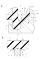
- An enlarged portion A in FIG. 4 shows a radial section of the stopper 26 portion.
- the stopper 26 has a sloped upper end surface so as to support the lower surface of the relief valve 33 (slope wall 35) when the valve is closed, and a general surface of the bottom portion 25 (a stopper in the valve portion 16b). It protrudes upward from the surface of the bottom portion other than 26 where the leak hole 29 is opened.
- An enlarged portion B in FIG. 4 shows a radial cross section of the leak hole 29 portion, and the leak hole 29 communicates with a leak passage 49 having a crescent shape in plan view.
- the inner peripheral surface of the annular partition wall 23 facing the leak passage 49 forms a seat surface 23a.
- the central opening 16c is an inner part of the inner peripheral annular wall 24 in which the movable film part 31 is accommodated, and a lower central opening 28 penetrates the bottom 25 of this part leaving a deformation regulating frame 28a having a substantially cross-shaped shape. Is formed.
- the radially outer end of the deformation restricting frame 28 a is continuously integrated with the inner peripheral annular wall 24 surrounding the central lower opening 28.
- the lower holder 17 is stacked below the lower holder 16 as necessary.
- the coupling protrusion 16g projecting downward from the bottom 25 of the lower holder 16 is fitted into a mounting hole of the mounting arm 17a projecting from the inner peripheral wall of the lower holder 17 and integrated by appropriate coupling means such as caulking to crush the tip. Turn into.
- the lower holder 17 is provided with an arc-shaped groove 17b opened upward, and communicates with the arc-shaped groove 22 through a communication port 22b at a position not shown. Moreover, it communicates with the auxiliary liquid chamber 7 through a communication port (not visible in this figure) formed in a part of the inner peripheral wall. Therefore, the orifice passage 8 can be made longer by making two steps by the arc-shaped grooves 22 and 17b.
- FIG. 6 is a perspective view of the elastic partition member 30, FIG. 7 is a plan view thereof, FIG. 8 is a front view, and FIG. 9 is a sectional view taken along line 9-9 of FIG.
- the elastic partition member 30 is made of a suitable elastic material such as rubber, and integrally includes a movable film portion 31 that is a thin center portion thereof, a fixed portion 32, and a relief valve 33 formed on the outer peripheral side of the fixed portion 32.
- the movable film portion 31 faces the central upper opening 18 and the central lower opening 28, is elastically deformed by the hydraulic fluid entering and exiting from these openings, and is a cross-shaped member that is a member for absorbing the internal pressure fluctuation of the main liquid chamber 5 by elastic deformation.
- the excessive deformation is restricted by the deformation restriction frames 18a and 28a.
- a plurality of protrusions 31a and protrusions 31b are integrally formed on the movable film portion 31 in a concentric manner, and when the movable film portion 31 is elastically deformed, the movable film portion 31 makes initial contact with the upper plate 15 and the lower holder 16 with a small contact area. It is like that.
- the fixed portion 32 is a thick and rigid annular wall formed on the outer peripheral side of the movable film portion 31, and the upper portion is positioned by a step portion 15b (see FIG. 5) in the outer peripheral portion of the central step portion 15a of the upper plate 15.
- the fixed base 39 is a restraining portion that is fixedly sandwiched between the upper plate 15 and the lower holder 16 by being fitted and positioned in the annular groove 27, and forms an annular support portion of the movable film portion 31. ing.
- the movable film portion 31 has an elliptical non-circular shape.
- the movable film portion 31 can be made into a non-circular shape other than an elliptical shape, and can also be made into a circular shape.
- the movable film part 31 of this embodiment makes an oval shape similar to the shape of the track for track and field, strictly speaking, this shape is also an ellipse.
- the fixed portion 32 that defines a part of the elliptical shape as an elliptical arc forms the outer periphery of the movable film portion 31, it also has an elliptical shape, and the outer peripheral portion of the fixed portion 32 from its center O.
- R (the outer diameter of the fixed portion 32) varies in the circumferential direction, and in the relationship with the relief valve 33, the portion near the intermediate portion P in the length direction of the relief valve 33 is the shortest R1, The vicinity of the portion corresponding to the vertical direction end Q is the longest R3.
- R2 is the radius in the middle between PQ.
- R1 is a short diameter
- R4 between the center O and the positioning protrusion 30a or a portion of the thick end 30b where the outer peripheral portion of the fixed portion 32 is extended is a long diameter.
- the major axis R4 is longer than R3.
- the longitudinal direction intermediate portion P of the relief valve 33 corresponds to a portion located radially outward from the fixed portion 32 on the short diameter R1 of the movable film portion 31 having an elliptical shape.
- the position corresponding to the lengthwise end Q is a portion located radially outward from the fixed portion 32 in the vicinity of the long diameter R4 of the movable film portion 31.
- a relatively enlarged space is provided in a portion on the radially outer side in the vicinity of the short diameter R1 of the movable film portion 31 in the outer peripheral portion of the elastic partition member 30, and this space is used.
- the maximum valve length portion of the relief valve 33 that is, the maximum opening width portion can be arranged efficiently.
- the relief valve 33 is divided into upper and lower parts in the figure by positioning protrusions 30a and thick end 30b formed on the left and right in FIG. 7, and the tip part 34, the slope wall 35, A circumferential groove 37 is provided.
- the relief valves 33 are long enough to form approximately half of the entire circumference of the outer periphery of the elastic partition member 30, and are provided as a pair facing each other in a crescent shape in plan view.
- the crescent shape of the relief valve 33 is formed between a tip portion 34 having an arc shape and an elliptical fixing portion 32. That is, when the inner and outer peripheries are formed by a combination of curves having different curvatures, the shape is formed by a combination in which the inner side is small and the outer side is large.
- the distal end portion 34 is a thick arc-shaped outer peripheral portion, and is a portion that is in liquid-tight contact with the outer peripheral wall surface of the leak passage 49 when the relief valve 33 is closed.
- the radius R0 of the tip 34 is constant over the entire circumference (R0 in the figure indicates the inner diameter).
- the circumferential end of the tip 34 is continuous to the positioning protrusion 30a and the thick end 30b. This connecting portion corresponds to the lengthwise end Q of the relief valve 33.
- the slope wall 35 is a main part of the relief valve 33 that is elastically deformed so as to bend when the relief valve 33 is opened and closed. Both ends in the length direction are continuous to the positioning protrusion 30a and the thick end 30b.
- the positioning protrusion 30 a and the thick end 30 b are thick and are the most rigid portions in the elastic partition member 30, and are portions that support the slope wall 35 in the length direction of the relief valve 33.
- the circumferential groove 37 is an elliptical arc-shaped concave groove provided in a similar shape to the outer periphery of the fixed portion 32 so as to extend along the circumferential direction, and is formed at the base portion of the inclined wall 35 connected to the outer peripheral portion of the fixed portion 32.
- the outer peripheral portion of the slope wall 35 has an arc shape by the tip portion 34
- the inner peripheral portion has an arc shape by the circumferential groove 37
- the vicinity of a certain positioning projection 30a and the thick end 30b is the narrowest, and the lengthwise intermediate portion P (the upper and lower portions in FIG. 7) is the widest.
- the leak hole 19 (FIG. 3) of the upper plate 15 is disposed so as to overlap the intermediate portion P in the length direction.
- the lower surface base portion 36a (details will be described later) of the relief valve 33 changes in height in the circumferential direction, the lengthwise intermediate portion P becomes the lowest H1, and the lengthwise end portion Q is the highest H2. It is continuously changing to become. Therefore, the base portion 36 is inclined obliquely upward from the longitudinal intermediate portion P toward the longitudinal end portions Q. Thereby, the valve length of the relief valve 33 is changed in the circumferential direction as will be described later.
- the position of the lower surface base 36a corresponds to the position of the bottom of the circumferential groove 37, and the position of the bottom of the circumferential groove 37 also changes in the length direction to form a bottom line E parallel to the lower surface base 36a (FIG. 10). However, the depth of the circumferential groove 37 is constant in the length direction.
- the relief valve 33 integrally has an inclined wall 35 that protrudes radially outward in a branching manner from the outer peripheral surface of the fixed portion 32 that forms an annular wall.
- the slope wall 35 forms an acute angle with respect to the fixed portion 32 and extends so as to expand obliquely upward in the radial direction, and both end portions in the circumferential direction are continuous to the positioning protrusion 30a and the thick end 30b. ing.
- a recess 38 is formed between the fixed portion 32 and the inclined wall 35 and is opened upward (toward the main liquid chamber).
- the circumferential end of the recess 38 is closed by a positioning protrusion 30a and a thick end 30b (see FIGS. 6 and 7).
- the opening width W which is the radial width of the concave portion 38, is the distance between the outer peripheral surface 32 a of the fixed portion 32 and the inner peripheral portion of the distal end portion 34, and varies in the length direction. Further, the depth D of the recess 38 (the length from the upper end of the relief valve 33 to the bottom center 37a of the circumferential groove 37 which is the lowest part of the recess 38) also changes in the length direction.
- the sealing surface 34a of the distal end portion 34 is formed substantially parallel to the sheet surface 23a of the annular partition wall 23, is in close contact with the sheet surface 23a with a relatively large sealing area, and is liquid-tight from the main liquid chamber side. The leak of the hydraulic fluid which goes to can be prevented now.
- the tip portion 34 is only a free end in the sense that the opening in the valve closing direction at the time of valve closing is restricted, and the movement in the valve opening direction is not restricted, and a certain amount of rigidity is provided at the tip portion of the relief valve 33.
- a thick-walled portion is provided to provide a uniform thickness, and can be uniformly deformed over the entire length in the circumferential direction.
- the valve length V which is the length of the lower surface of the inclined wall 35 in the illustrated cross section, varies in the circumferential direction.
- the valve length V is the distance between the intersection points of the lower surface of the inclined wall 35, the outer peripheral surface 39 a of the fixed base 39, and the seal surface 34 a of the distal end portion 34.
- the intersection of the lower surface of the slope wall 35 and the outer peripheral surface 39a of the fixed base 39 is particularly referred to as a lower surface base 36a.
- This valve length affects the opening / closing operation of the relief valve 33. Further, changing the valve length in the circumferential direction has an important effect on the valve opening characteristics, which will be described in detail later.
- the intersection of the extension and the outer peripheral surface 39a simply forms the lower surface base 36a, but the lower surface of the slope wall 35 is curved. None, and further, when connecting with the outer peripheral surface 39a by a radius, the intersection of the outer peripheral surface 39a on the lower surface of the slope wall 35 excluding the radius and the outer peripheral surface 39a when the latest curve is extended is defined as the lower surface base 36a. .
- the base portion 36 of the relief valve 33 connected to the fixed portion 32 forms a thin portion for bending by a circumferential groove 37 formed on the upper side on the concave portion 38 side, so that the relief valve 33 can be easily bent when the valve is opened and closed.
- the circumferential groove 37 is a groove having an arc cross section formed by carving the upper side of the base portion 36 downward from the concave portion 38 side.
- the circumferential groove 37 is open upward and forms an elliptical arc shape along the outer peripheral side of the fixed portion 32. It is formed long.
- the base portion 36 becomes thinner than the wall thickness of the slope wall 35 due to the circumferential groove 37, and the slope wall 35 is easily bent with the circumferential groove 37 as a bending start point. For this reason, the relief valve 33 can be smoothly opened by bending the circumferential groove 37 and bending the inclined wall 35 when abnormal vibration is input, as indicated by a virtual line in the enlarged portion.
- the thickness of the base portion 36 Since the thickness of the base portion 36 has a great influence during the opening / closing operation of the relief valve 33, the thickness is adjusted to an optimum value by adjusting the size and depth of the circumferential groove 37. As the thickness of the base portion 36 is reduced, the relief valve 33 can be bent and opened toward the fixing portion 32 with a small force with the circumferential groove 37 as a bending base point when the relief valve 33 receives a hydraulic pressure from below in the drawing.
- the inclined wall 35 is made relatively thick and has a certain degree of bending rigidity, so that when the valve is closed, the inclined wall 35 is not easily deformed by the hydraulic pressure from the main liquid chamber side (upward in the figure) so that the hydraulic fluid does not leak. Thus, a high attenuation is set.
- the rigidity of the relief valve 33 at the time of valve closing is increased to prevent the leakage, and the slope wall 35 is easily bent so as to quickly open and leak under the condition of cavitation generation at the time of abnormal vibration input.
- the characteristic at the time of valve opening is set by the circumferential change of the valve length and the circumferential groove 37 in the base portion 36.
- the ease of bending by the circumferential groove 37 can be adjusted by the relationship with the fixed base 39 that is the lower part of the fixed portion 32. That is, the fixed base 39 is thicker in the radial direction than the fixed portion 32, and the outer peripheral surface 39 a projects outward in the radial direction from the outer peripheral surface 32 a of the fixed portion 32.
- perpendicular lines in contact with the inner circumferential surface of the circumferential groove 37 (which coincides with the outer circumferential surface 32a of the fixing portion 32) and the outer circumferential surface 35a (the inner circumferential surface of the inclined wall 35 facing the circumferential groove 37) are denoted by L1 and L2.
- the vertical line passing through the bottom center 37a of the circumferential groove 37 is L3 and the vertical line in contact with the outer peripheral surface 39a of the fixed base 39 is L4
- the vertical line L3 passes through the center side of the outer peripheral surface 39a of the fixed base 39.
- the rigidity of the slope wall 35 is set to an optimum size for maintaining high attenuation.
- the valve can be opened most appropriately.
- the position of the lower surface base portion 36a is optimal on the vertical line L3, but if the vertical line L4 is between L3 and L2, a certain degree of effect can be obtained in the balance between the rigidity of the relief valve 33 and the optimal valve opening characteristics. .
- FIG. 10 is a partial cross-sectional view showing a change in the valve length of the relief valve 33, where A is a 10A-10A cross section, B is a 10B-10B cross section, and C is a 10C-10C cross section.
- this cross-sectional portion is at the intermediate portion P in the length direction of the relief valve 33, and the radius R0 of the tip end portion 34 is constant all around, but the radius R1 of the fixed portion 32 is minimized.
- the opening width W1 of the recess 38 is maximized. Further, the depth D1 of the recess 38 is maximized.
- a bottom line E in the figure is a line connecting the bottom center 37a of the circumferential groove 37 in the length direction, and is a straight line parallel to a line connecting the lower surface base 36a in the circumferential direction, and is from A to C
- the bottom center 37a of the circumferential groove 37 is located on this straight line.
- the depth of the concave portion 38 gradually decreases along the bottom line E from the circumferential intermediate portion (A in the drawing) toward the circumferential end portion (C in the drawing).
- this cross-sectional part is in the middle between the longitudinal direction intermediate portion P and the longitudinal direction end portion Q of the relief valve 33, and the radius R2 of the fixed portion 32 is larger than R1, and the opening of the recess 38 is opened.
- the width W2 and the depth D2 are smaller than W1 and D1, respectively. For this reason, valve length V2 becomes shorter than V1, and it becomes difficult to bend.
- this cross-sectional portion is in the vicinity of the longitudinal end Q of the relief valve 33, the radius R3 of the fixed portion 32 is maximized, and the opening width W3 and depth D3 of the recess 38 are minimized. (R1 ⁇ R2 ⁇ R3, W1>W2> W3, D1>D2> D3). For this reason, the valve length V3 is minimized (V1>V2> V3), and this portion is most difficult to bend.
- the operation of the present embodiment will be described with reference to FIGS.
- the main liquid chamber 5 when abnormal vibration is input to the main liquid chamber 5 from the Z direction, the main liquid chamber 5 is compressed and the hydraulic fluid is sent out to the sub liquid chamber 7 side.
- the hydraulic fluid in the main liquid chamber 5 is pressurized and pushes the upper surface of the inclined wall 35 of the relief valve 33 toward the lower liquid chamber 7 side.
- the slope wall 35 of the relief valve 33 is made thick to a certain extent and has high rigidity, and is set so as not to cause valve opening deformation at a hydraulic pressure level due to vibration input in a normal range.
- the sealing surface 34a of the tip 34 maintains close contact with the seat surface 23a of the annular partition wall 23 to prevent hydraulic fluid leakage (see the enlarged portion in FIG. 4), strengthening the liquid column resonance by the orifice passage 8 and high attenuation. Can be.
- the slope wall 35 is pushed into the lower liquid chamber 7 side even if the liquid pressure on the main liquid chamber 5 side is somewhat high. In this manner, the deformation of the relief valve 33 can be prevented, so that the leakage of the working fluid can also be prevented. In addition, even if abnormal vibration is input, the relief of the relief valve 33 can be prevented by supporting the stopper 26, thereby preventing leakage.
- the stopper 26 is provided in the vicinity of the intermediate portion P in the length direction, the opening of the inclined wall 35 in the intermediate portion in the length direction of the relief valve 33 that is most easily deformed against the hydraulic pressure from the main liquid chamber 5 side. Valve deformation can be effectively prevented. Furthermore, if a plurality of stoppers 26 are provided in the middle of the lengthwise intermediate portion P and the lengthwise end portion Q, a plurality of stoppers 26 can be supported more reliably. Therefore, even if the relief valve 33 is formed so as to be about a half of the outer circumference of the elastic partition member 30, leakage from the main liquid chamber 5 side can be prevented.
- the volume of the main liquid chamber 5 quickly returns to the state before compression when the vibration direction is reversed, so that the inside of the main liquid chamber 5 instantaneously approaches a negative pressure state.
- the relief valve 33 is pulled from the main liquid chamber 5 side and pushed up by the hydraulic fluid from the sub liquid chamber 7 side and this force overcomes the rigidity of the relief valve 33, the relief valve 33 is deformed to open.
- the seal surface 34a opens away from the seat surface 23a, and the working fluid on the side of the sub liquid chamber 7 is Sub liquid chamber 7 ⁇ Leak hole 29 ⁇ Leak passage 49 ⁇ Leak hole 19 ⁇ Main liquid chamber 5, And let it leak. Thereby, a large amount of hydraulic fluid is smoothly leaked from the leak hole 19 to the main liquid chamber 5, and the occurrence of a cavitation phenomenon in the main liquid chamber 5 can be reliably prevented.
- the relief valve 33 is formed long in a substantially semi-elliptical arc shape that is nearly half of the entire circumference of the outer peripheral portion of the elastic partition member 30, and further, the valve length is changed in the circumferential direction and the lengthwise intermediate portion P The maximum in the circumferential direction is opened first.
- the hydraulic fluid concentrates here, so that the adjacent portion where the hydraulic fluid is opened is pushed open, and the opening further toward the longitudinal end Q. It expands rapidly, and almost the entire relief valve 33 can be opened in a very short time.
- the valve is firstly valved so that the slope wall is turned up toward both end portions Q from this length as a starting point. Bend 35 to open. For this reason, the relief valve 33 is smoothly opened over almost the entire length, and can be opened quickly and reliably.
- this portion can be reliably used as the valve separation start portion.
- the inclined wall 35 has an inclined surface, the working fluid on the side of the auxiliary liquid chamber 7 is guided to the inclined surface and concentrated on the tip of the relief valve 33. Therefore, the tip of the relief valve 33 is deformed so as to turn.
- the seal surface 34a can be separated smoothly from the seat surface 23a.
- the slope wall 35 has a relatively high rigidity, and the distal end portion 34 has a thicker and higher rigidity structure, so that the relief valve 33 is locally irregularly deformed in the length direction. Without this, the entire relief valve 33 can be continuously deformed.
- the circumferential groove 37 is provided so as to extend in the circumferential direction, the inclined wall 35 bends smoothly starting from the circumferential groove 37. For this reason, the relief valve 33 can be opened quickly with almost the entire length, and a leak can be generated in the entire outer peripheral portion of the relief valve 33.
- the position of the lower surface base portion 36a is positioned at the middle portion of the bottom center 37a of the circumferential groove 37 and the outer circumferential surface 35a of the circumferential groove 37, so that the balance between the relatively high rigidity and the bendability of the inclined wall 35 is achieved. Can be optimally balanced. Further, since the relief valve 33 is on the inner peripheral side of the annular partition wall 23 and has a long peripheral length, a large opening area can be formed. Also in this respect, a large amount of hydraulic fluid can be instantaneously leaked, and the occurrence of a cavitation phenomenon is ensured. Can be prevented.
- the balance between the improvement in rigidity and the ease of opening the valve is balanced, and the rigidity that does not deform to prevent leakage at the time of normal vibration input and the abnormal vibration input Sometimes it can be deformed quickly and can be easily opened to allow a large amount of leakage.
- the leak passage 49 is formed to be long in the circumferential direction so as to have an opening area. Therefore, a large amount of leakage is enabled when the relief valve 33 is opened.
- valve length of the relief valve 33 is changed in the length direction, the portion in the middle portion P in the length direction is maximized to ensure valve opening ease, and the portion on the length direction end portion Q side is minimized to be rigid. Therefore, the valve opening ease can be ensured while maintaining high rigidity over the entire length. Therefore, even if a large amount of hydraulic fluid leaks is realized by lengthening the relief valve 33 to increase the opening area at the time of opening the valve, the rigidity and the ease of opening the valve can be reliably combined.
- the leak passage 49 can be crescent shaped and the opening area can be increased
- the inner peripheral side has an elliptical arc shape, so that the movable film portion 31 can be formed into an elliptical shape, and the required area Can be secured. Therefore, the hydraulic pressure absorption performance can be maintained without reducing the area of the movable film portion 31.
- the outer periphery of the elastic partition member 30 has the same circular shape as before and the outer diameter R0 does not change, the increase in the outer diameter of the partition member 6 is prevented, and the device is prevented from being enlarged to have a compact outer shape. Can be maintained.
- FIG. 11 is a graph showing dynamic spring characteristics, in which the horizontal axis represents cavitation noise transmission force (N) and the vertical axis represents damping force (N ⁇ s / mm).
- the cavitation noise transmission force is an index indicating the magnitude of the noise during cavitation transmitted to the vehicle body, and the smaller this value, the more cavitation can be suppressed.
- the solid line in the figure is the characteristic of the present invention, and the broken line is a comparative example.
- the comparative example is shown as A below the graph, and has a relief valve 33 that is only in the shape of an arc, compared to the one shown in B in which the relief valve 33 having an elliptical arc shape according to the present invention is provided.
- the number and length of relief valves are the same.
- FIG. 12 there is a structure shown in FIG. 12 that facilitates valve opening.
- 12A is a cross-sectional view of the same portion as the enlarged portion of FIG. 9 of the relief valve 33
- B is a cross-sectional view taken along line BB in A.
- FIG. 12A is a cross-sectional view of the same portion as the enlarged portion of FIG. 9 of the relief valve 33
- B is a cross-sectional view taken along line BB in A.
- a radial groove 40 is provided on the upper surface, which is the surface of the inclined wall 35 on the main liquid chamber 5 side.
- the radial groove 40 is a concave groove that is opened toward the main liquid chamber 5 side, and is formed so as to bite into the wall thickness from the upper surface of the inclined wall 35, and extends in the radial direction of the relief valve 33.
- the end reaches the circumferential groove 37, and the outer end reaches the tip 34.
- the position where the radial groove 40 is formed is a position passing through the length direction intermediate portion P of the relief valve 33 and its vicinity. However, a plurality of them can be provided.
- Providing the radial groove 40 in this way can facilitate valve opening ease in the vicinity of the lengthwise intermediate portion P. That is, as shown in B, at the time of abnormal vibration input, the inclined wall 35 is pulled from the main liquid chamber 5 side, and hydraulic pressure is applied from the sub liquid chamber 7 side. Then, the hydraulic fluid on the side of the secondary liquid chamber 7 pushes the inclined wall 35 toward the main liquid chamber 5 side as indicated by an arrow a. However, in the portion where the radial groove 40 is provided, the hydraulic fluid is thin by the radial groove 40. Since it is easy to bend, it is deformed so as to be bent toward the main liquid chamber 5 side as indicated by an arrow b around the radial groove 40, and this deformation extends to the tip 34. For this reason, the seal surface 34a in the vicinity of the radial groove 40 in the distal end portion 34 is likely to be separated from the seat surface 23a, and the valve is promptly released.
- FIG. 13 shows another proposal for facilitating valve opening.
- FIG. 13A corresponds to FIG. 12A.
- the inclined wall 35 is pushed up to the main liquid chamber 5 side by a stopper 26 that supports a lower surface that is a surface on the side of the sub liquid chamber 7.
- FIG. 13 is a BB cross section of A.
- the support surface 26a of the stopper 26 has a curved surface that protrudes toward the main liquid chamber 5 side. Therefore, the support surface 26a is supported while being pushed out so as to push the slope wall 35 toward the main liquid chamber 5 side so that the tip of the support surface 26a bites into the lower surface of the slope wall 35.
- This push-out support is set to be performed from an initial state, that is, a state where no vibration is input.
- the support surface 26a Since the support surface 26a has a curved surface, only the tip portion contacts the slope wall 35 in a narrow range in a substantially line contact manner, and between the support surface 26a excluding this contact portion and the lower surface of the slope wall 35, A slight gap 41 is formed.
- the gap forms a substantially wedge-shaped cross section that tapers toward the contact portion between the support surface 26a and the lower surface of the inclined wall 35. Therefore, when a hydraulic pressure is applied from the auxiliary liquid chamber 7 side during abnormal vibration input, the hydraulic fluid in the auxiliary liquid chamber 7 side pushes the inclined wall 35 toward the main liquid chamber 5 side as indicated by an arrow a. A part thereof goes into the gap 41 and tries to push up the inclined wall 35 so as to be separated from the support surface 26a.
- the inclined wall 35 is deformed so as to bend toward the main liquid chamber 5 at the support portion with the stopper 26.
- the seal surface 34a at the tip end portion 34 is easily separated from the sheet surface 23a, and is promptly separated. I speak.
- the support surface 26a of the stopper 26 has a small contact area that makes a substantially line contact with the inclined wall 35, the friction is less likely to be separated.
- the inclined wall 35 is urged to be pushed out to the main liquid chamber 5 side in the initial state, this facilitates separation. For this reason, the ease of valve opening in the part supported by the stopper 26 can be promoted.
- This structure can also be applied to the structure provided with the radial grooves in FIG.
- FIG. 14 is a plan view of the elastic partition member 30 corresponding to FIG. 7, and FIG. 15 is a cross-sectional view of a different part of the relief valve 33 similar to FIG.
- the relief valve 33 is shortened. In this example, it is formed in an arc shape of about 1/6 of the circumference. However, the length of the relief valve 33 can be set freely. The curvatures of the outer peripheral side and the inner peripheral side of the relief valve 33 are different, the valve length changes in the circumferential direction, and the movable film part 31 is elliptical as in the previous embodiment.
- a portion of the elastic partition member 30 on the outer peripheral side of the fixed portion 32 and sandwiched between the positioning projection 30a and the thick end 30b is defined as a valve region 50.
- two orthogonal axes passing through the center of the elastic partition member 30 are X and Y and the X axis is passed over the positioning projection 30a and the thick end 30b, the intermediate point in the length direction of the relief valve 33 on the Y axis Arranged so that P is located.
- the relief valve 33 extends the valve region 50 to both sides in the circumferential direction across the Y axis. However, since the circumferential length of the relief valve 33 is relatively short, there is a gap between the relief valve 33 and the positioning protrusion 30a and the thick end 30b. In addition, a valve non-forming portion 51 in which the relief valve 33 is not formed is formed.
- the relief valve 33 in the present embodiment is different from the previous embodiment in that the circumferential length is shortened, and in this way, the relief valve 33 is formed up to the valve non-forming portion 51 in the previous embodiment.
- FIG. 15 is a cross section of the relief valve 33 in FIG. 14.
- FIG. 15A is a cross section taken along the line 15A-15A
- FIG. 15B is a cross section taken along the line 15B-15B
- FIG. 15C is a cross section taken along the line 15C-15C. It is.
- the valve length is expressed by the distance between the outer peripheral surfaces of the fixed portion 32 and the distal end portion 34 of the relief valve 33
- the distance S1 in FIG. 15A is the maximum
- the distance S2 in FIG. 15 changes to be intermediate (S1 ⁇ S2 ⁇ S3)
- the valve length also changes gradually from A in FIG. 15 to C in FIG. That is, it is the same as in the previous embodiment that the valve length at the circumferential intermediate portion is maximized and the valve length at the circumferential end is minimized.
- the change in the valve length does not depend on the change in the depth of the circumferential groove 37 as in the previous embodiment, but the valve angle when the depth is constant.
- the valve angle which is the angle formed between the outer peripheral surface of the fixed base 39 and the surface of the inclined wall 35 on the side of the secondary liquid chamber 7, changes.
- A is ⁇ 1
- B is ⁇ 2
- C is ⁇ 3
- ⁇ 1 ⁇ 2 ⁇ 3 gradually increases toward the end in the circumferential direction. That is, it has a valve angle changing structure.
- valve length can be changed and can be changed so as to be the longest in the central portion in the circumferential direction.
- the valve angle by changing the valve angle, the height of the tip of the relief valve 33 can be made constant even if the valve length changes. Therefore, at the circumferential end, the valve length is minimum and the valve angle is maximum, and the bending when the relief valve 33 is opened is minimized.
- the valve non-forming portion 51 is a portion of the valve region 50 where the relief valve 33 is not formed, and is a portion where the recess 38 for forming the relief valve 33 is not provided. However, an elasticity adjusting portion 52 for adjusting the elasticity of the valve non-forming portion 51 is formed in this portion.
- the elasticity adjusting portion 52 is a groove-like concave portion having an arc shape in a plan view of FIG. 14 and is open toward the main liquid chamber 5 side, but does not face the leak passage 49 and is a relief valve like the concave portion 38. 33 is not for forming the valve 33, but for reducing the rigidity of the non-valve forming portion 51 to give an appropriate elasticity to this portion.
- the leak passage 49 has a relatively short circumferential length formed only in a portion overlapping the relief valve 33 that is short in the circumferential direction, and is not formed in a portion overlapping the valve non-forming portion 51.
- the shape, size, depth, and the like of the elasticity adjusting unit 52 are arbitrarily set according to the elasticity required for the valve non-forming part 51.
- the elasticity adjusting portion 52 may be formed so as not to penetrate the valve non-forming portion 51 in the vertical direction in the figure, and the opening direction thereof may be formed toward the lower auxiliary liquid chamber 7 side.
- this elasticity adjusting portion 52 If this elasticity adjusting portion 52 is not provided, the rigidity of the valve non-forming portion 51 becomes high, and this portion is tightly sealed between the annular partition wall 23 of the lower holder 16 and the inner peripheral annular wall 24 (see FIG. 4).
- a large reaction force is generated in the non-valve forming portion 51 due to the compression of the elastic body, which acts on the movable film portion 31 and bends toward the sub liquid chamber 7 side. In some cases, it may be impossible to secure a sufficient damping force.
- the elasticity adjusting portion 52 in the valve non-forming portion 51 and adjusting the elasticity it is possible to suppress the generation of a large reaction force and prevent the movable film portion 31 from being bent more than necessary. Moreover, the damping performance can be maintained by the short relief valve 33 described above.
- the outer peripheral shape of the elastic partition member 30 in a plan view is not limited to a circle, but may be a non-circular shape including an ellipse or a polygon.
- FIG. 16 shows a third embodiment in which the outer peripheral portion of the elastic partition member 30 has an elliptical shape and the movable film portion 31 has a circular shape.
- FIG. 16 schematically shows the shape of the elastic partition member 30 in plan view
- the elastic partition member 30 is an ellipse having a major axis a and a minor axis b.
- the major axis “a” and the minor axis “b” overlap with two orthogonal axes X and Y passing through the center O of the elastic partition member 30.
- the movable film portion 31 is provided inside the elastic partition member 30 so as to have a circular shape in plan view.
- the space inside the outer peripheral part of the elastic partition member 30 and outside the movable film part 31 is widened in the vicinity of the major axis “a” in the radial direction and is narrowest in the vicinity of the minor axis “b”.
- a pair of relief valves 33 indicated by hatching is provided facing each other.
- Each relief valve 33 has a crescent shape, and the middle portion in the longitudinal direction having the widest opening width is located on the major axis a, and extends from both sides toward the minor axis b side while gradually narrowing the opening width. .
- Both ends in the length direction of the relief valve 33 are located in the vicinity of the short axis b, and the inner and outer circumferences are connected in a round shape.
- the length of each relief valve 33 is slightly shorter than approximately 1 ⁇ 2 of the entire length of the outer peripheral portion of the elastic partition member 30.
- a pair of long relief valves 33 can be provided.
- a valve non-forming portion 51A is formed between the longitudinal ends of the relief valve 33 facing each other across the short axis b.
- a non-circular movable film part like a 1st and 2nd Example can also be combined with a non-circular elastic partition member.
- the elastic partition member and the movable film portion can each be circular, and a relief valve can be provided in a ring-shaped space formed by them.
- the relief valve in this case is the same as the valve length described so far changing in the length direction.
- this non-circular is not limited to an elliptical shape.
- oval shapes and polygons including oval shapes, combined shapes with these and circles and ellipses, shapes with irregularities provided with small circular protrusions or recesses around large circles, and various irregular shapes, etc. Is possible.
- the relief valve when it has a crescent shape in plan view, it can be easily formed into a crescent shape if either one of the inner and outer circumferences is an elliptical arc and the other is an arc, but only by such a combination of an elliptical arc and an arc.
- it can be formed by arranging arcs with different curvatures on the inner and outer circumferences, or by shifting and overlapping arcs with the same curvature.
- the inner and outer peripheries can be formed by two elliptical arcs having different flatness rates.
- the length of the relief valve is not limited to about 1/2 of the entire length of the outer peripheral portion of the elastic partition member, but may be only one as long as possible covering almost the entire circumference. Or it may be as short as 1/4.
Abstract
Description
The present invention relates to a liquid seal vibration isolator used for an engine mount or the like of an automobile, and more particularly to an apparatus capable of effectively reducing abnormal noise caused by a cavitation phenomenon and realizing high attenuation.
このうちの一つとして、仕切部材の一部に可動膜部を設け、この可動膜部の外周部に円弧状をなすリリーフバルブを一体に設け、通常振動(一般走行時等において想定される範囲の振動)の入力時には仕切部材に設けたリーク通路を閉じ、異常振動の入力時には、リリーフバルブを開いて副液室から主液室内へ大量の作動液をリークさせるようにしたものがある(特許文献1参照)。
ここで異常振動とは、キャビテーションを発生するような過大振幅の振動であり、一般走行時等の通常では生じない振動である。
As one of them, a movable film part is provided in a part of the partition member, and an arc-shaped relief valve is integrally provided on the outer peripheral part of the movable film part, so that normal vibration (range assumed in general traveling etc.) The leak passage provided in the partition member is closed when the vibration is input, and when the abnormal vibration is input, a relief valve is opened to leak a large amount of hydraulic fluid from the secondary liquid chamber to the main liquid chamber (patent) Reference 1).
Here, the abnormal vibration is vibration with an excessive amplitude that generates cavitation, and is vibration that does not normally occur during general traveling or the like.
一方、異常振動入力時には、リリーフバルブが短時間で大きく開くことにより、できるだけ大量の作動液を瞬時にリークさせる必要がある。
このため、リリーフバルブは異常振動入力時に開き易くし、かつ開口面積を大きくするように開き方向へ素早く変形できる開弁容易性が求められている。しかし、このような剛性向上と開弁容易性は相反する性質ものであるから、これらをバランスさせ、通常の振動入力時にはリークを阻止するために変形しない程度の剛性と、異常振動入力時には速やかに変形して大量のリークを可能にする開弁容易性とを兼備することが求められている。
また、リリーフバルブ開弁時における大量のリークを可能にするためには、リーク通路を可動膜部の外周部に沿って周方向へ長く形成して開口面積を大きくすることが考えられる。
しかし、このようにすると、リリーフバルブもリーク通路にあわせて可動膜部の周方向へ長く形成する必要があるが、長くなるだけ剛性が低下することになるので、全長に亘って高い剛性を維持しなければならないから、開弁容易性が損なわれやすくなる。したがって、リリーフバルブを長くする場合には、上記剛性と開弁容易性の兼備がより重要になる。
さらに、リーク通路の開口面積を大きくすることによって、リリーフバルブの内側に設けられている可動膜部の面積を減少させて液圧吸収性能を低下させたり、逆に仕切部材の外径を大きくして装置のコンパクト化を阻害するようなことは回避しなければならない。
そこで、本願は上記諸要請の実現を目的とする。
By the way, in the above relief valve, when the input vibration is in the normal range, it is necessary to close the leak passage in a liquid-tight manner and not leak the working fluid, and to ensure high attenuation due to liquid column resonance in the orifice passage. It is necessary to prevent the hydraulic fluid from leaking without making a deformation that causes the valve to open by normal vibration input (hereinafter referred to as “opening deformation”), making the relief valve rigid as high as possible to maintain fluid tightness.
On the other hand, when an abnormal vibration is input, it is necessary to instantly leak as much hydraulic fluid as possible by opening the relief valve greatly in a short time.
For this reason, the relief valve is required to be easily opened when abnormal vibration is input and to be easily deformable in the opening direction so as to increase the opening area. However, since this improvement in rigidity and ease of valve opening are contradictory properties, they are balanced so that they do not deform to prevent leakage during normal vibration input, and quickly when abnormal vibration is input. It is required to combine the ease of opening of a valve that can be deformed to allow a large amount of leakage.
In order to enable a large amount of leak when the relief valve is opened, it is conceivable to increase the opening area by forming a leak passage long in the circumferential direction along the outer peripheral portion of the movable film portion.
However, if this is done, the relief valve also needs to be formed longer in the circumferential direction of the movable membrane part along with the leak passage. However, since the rigidity will decrease as the length increases, high rigidity is maintained over the entire length. Therefore, the ease of opening the valve tends to be impaired. Therefore, when the relief valve is lengthened, the combination of the rigidity and the ease of opening is more important.
Furthermore, by increasing the opening area of the leak passage, the area of the movable membrane provided inside the relief valve can be reduced to reduce the hydraulic pressure absorption performance, or conversely, the outer diameter of the partition member can be increased. Therefore, it must be avoided that the device is downsized.
Therefore, the present application aims to realize the above-mentioned various requirements.
前記仕切部材(6)に弾性仕切部材(30)を設け、この弾性仕切部材(30)に、
主液室(5)の液圧変動を吸収する中央部の可動膜部(31)と、
前記仕切部材(6)に設けられたリーク通路(49)を開閉する外周部のリリーフバルブ(33)とを一体に設け、
異常振動入力時に前記リリーフバルブ(33)を開いて、前記リーク通路(49)から作動液を主液室へリークさせることによりキャビテーションの発生を抑制するようにした液封防振装置において、
前記リリーフバルブ(33)は、前記弾性仕切部材(30)の外周部周方向に沿って形成され、
前記主液室(5)側へ開放された凹部(38)と、この凹部(38)の外周壁をなす斜面壁(35)を備え、
この斜面壁(35)の径方向長さである弁長を前記リリーフバルブ(33)の長さ方向において変化させるとともに、
この弁長は、前記リリーフバルブ(33)の長さ方向中間部(P)が最大になるように変化していることを特徴とする。 In order to solve the above-mentioned problem, the invention according to
The partition member (6) is provided with an elastic partition member (30), and the elastic partition member (30)
A central movable film portion (31) that absorbs fluid pressure fluctuations in the main fluid chamber (5);
An integrally provided relief valve (33) on the outer periphery that opens and closes the leak passage (49) provided in the partition member (6),
In the liquid seal vibration isolator which prevents the occurrence of cavitation by opening the relief valve (33) at the time of abnormal vibration input and leaking the hydraulic fluid from the leak passage (49) to the main liquid chamber,
The relief valve (33) is formed along the circumferential direction of the outer periphery of the elastic partition member (30),
A concave portion (38) opened to the main liquid chamber (5) side, and an inclined wall (35) forming an outer peripheral wall of the concave portion (38),
While changing the valve length, which is the radial length of the inclined wall (35), in the length direction of the relief valve (33),
This valve length is characterized in that the lengthwise intermediate portion (P) of the relief valve (33) changes so as to become maximum.
前記凹部(38)の開口幅は、前記リリーフバルブ(33)の長さ方向において変化し、
前記リリーフバルブ(33)の長さ方向中間部(P)が最大になるように変化していることを特徴とする。 The invention of
The opening width of the recess (38) varies in the length direction of the relief valve (33),
The relief valve (33) has a lengthwise intermediate portion (P) that changes so as to be maximized.
前記リリーフバルブ(33)が前記弾性仕切部材(30)の平面視にて、三日月状をなしていることを特徴とする。
ここで三日月形状とは、内外2つの曲線を組み合わせて形成される細長い形状であって、長さ方向両端が閉じられ、2つの曲線の間隔が、中間部で最も広がり、長さ方向端部に向かって次第に狭くなるように変化する形状であり、例えば、外側の曲線の曲率よりも内側の曲線の曲率を小さくすることによって形成される。 The invention of
The relief valve (33) has a crescent shape in plan view of the elastic partition member (30).
Here, the crescent shape is an elongated shape formed by combining two curves inside and outside, both ends in the length direction are closed, and the interval between the two curves is widest at the middle portion, and at the end in the length direction. For example, it is formed by making the curvature of the inner curve smaller than the curvature of the outer curve.
前記リリーフバルブ(33)は、前記弾性仕切部材(30)の平面視にて、内周側又は外周側のいずれか一方を楕円弧、他方を円弧とする異なる2曲線で形成されていることを特徴とする。 A fourth aspect of the present invention provides the method according to any one of the first to third aspects,
The relief valve (33) is formed by two different curves in which either the inner peripheral side or the outer peripheral side is an elliptical arc and the other is an arc in a plan view of the elastic partition member (30). And
前記弾性仕切部材(30)の前記可動膜部(31)は、平面視で非円形をなしていることを特徴とする。 A fifth aspect of the present invention provides the method according to any one of the first to fourth aspects,
The movable film part (31) of the elastic partition member (30) is non-circular in plan view.
前記リリーフバルブ(33)は、前記弾性仕切部材(30)における外周部全周の略1/2程度の長さで、中心を挟んで対称に一対で設けられていることを特徴とする。 A sixth aspect of the present invention relates to any one of the first to fifth aspects,
The relief valve (33) has a length of about ½ of the entire circumference of the outer periphery of the elastic partition member (30), and is provided as a pair symmetrically across the center.
前記弾性仕切部材(30)は、前記可動膜部(31)の外周部を固定するために設けられた厚肉の固定部(32)を備え、この固定部(32)より外周側部分は前記リリーフバルブ(33)が形成されるバルブ領域(50)をなすとともに、
このバルブ領域(50)における前記リリーフバルブ(33)の周方向端部近傍部はバルブ非形成部(51)をなし、このバルブ非形成部(51)にその弾力を調整するための弾力調整部(52)を設けたことを特徴とする。 A seventh aspect of the present invention provides the method according to any one of the first to fifth aspects,
The elastic partition member (30) includes a thick fixing portion (32) provided for fixing the outer peripheral portion of the movable film portion (31), and the outer peripheral portion of the fixing portion (32) is Forming a valve region (50) in which the relief valve (33) is formed;
The vicinity of the circumferential end of the relief valve (33) in the valve region (50) forms a valve non-forming part (51), and an elasticity adjusting part for adjusting the elasticity of the valve non-forming part (51). (52) is provided.
前記斜面壁(35)の前記主液室(5)に臨む面に、主液室(5)へ開放されて径方向へ延びる径方向溝(40)を設けたことを特徴とする。 The invention of
A surface of the inclined wall (35) facing the main liquid chamber (5) is provided with a radial groove (40) that opens to the main liquid chamber (5) and extends in the radial direction.
前記斜面壁(35)は、前記副液室(7)側の面を、前記リーク通路(49)内に形成されたストッパ(26)により支持されるとともに、前記ストッパ(26)は初期状態で前記斜面壁(35)を支持部にて前記主液室(5)側へ押し出していることを特徴とする。 A ninth aspect of the present invention provides the method according to any one of the first to eighth aspects,
The inclined wall (35) is supported on the side of the sub liquid chamber (7) by a stopper (26) formed in the leak passage (49), and the stopper (26) is in an initial state. The inclined wall (35) is pushed out to the main liquid chamber (5) side by a support portion.
前記弾性仕切部材(30)は前記可動膜部(31)の外周部を固定するために設けられた厚肉の固定部(32)を備え、前記リリーフバルブ(33)の斜面壁(35)は前記固定部(32)から径方向外方へ一体に突出し、この斜面壁(35)の前記固定部(32)へ接続する基部(36)で前記主液室(5)側の面に、長さ方向へ延びる弧状の凹溝である周方向溝(37)が形成されるとともに、
前記固定部(32)よりも厚肉で固定部(32)と連続一体であり、前記基部(36)から前記副液室(7)側へ延出する固定基部(39)を備え、
この固定基部(39)の外周面(39a)が、前記周方向溝(37)の底部中心(37a)よりも径方向外方に位置することを特徴とする。
The invention of
The elastic partition member (30) includes a thick fixing part (32) provided to fix the outer peripheral part of the movable film part (31), and the inclined wall (35) of the relief valve (33) A base portion (36) that protrudes radially outward from the fixing portion (32) and connects to the fixing portion (32) of the inclined wall (35) is long on the surface on the main liquid chamber (5) side. A circumferential groove (37) that is an arcuate groove extending in the lengthwise direction is formed,
A fixed base (39) that is thicker than the fixed part (32) and is continuous and integrated with the fixed part (32), and extends from the base (36) to the sub liquid chamber (7) side,
The outer peripheral surface (39a) of the fixed base portion (39) is located radially outward from the bottom center (37a) of the circumferential groove (37).
したがって、剛性向上と開弁容易性との相反するものをバランスさせ、通常の振動入力時にはリークを阻止するために変形しない程度の剛性と、異常振動入力時には速やかに変形して大量のリークを可能にする開弁容易性とを兼備することができる。 According to the first aspect of the present invention, since the valve length of the relief valve is changed in the length direction of the relief valve, and the intermediate portion in the length direction of the relief valve is changed to the maximum, the length of the relief valve is increased. The middle part in the direction can be most easily deformed, and the valve can be quickly opened from here. In addition, the end of the length direction has a short valve length and is difficult to be deformed, so that the rigidity is increased.
Therefore, it balances the contradictory of improved rigidity and ease of valve opening, so that it does not deform in order to prevent leaks during normal vibration input, and it can deform quickly and generate large amounts of leaks when abnormal vibration is input. It is possible to combine the ease of opening the valve.
According to the invention of
According to the tenth aspect of the present invention, the circumferential groove, which is an arc-shaped concave groove provided in the base of the relief valve, can facilitate the bending of the relief valve and facilitate the opening of the relief valve when abnormal vibration is input. Since the outer peripheral surface of the thick fixed base continuous to the fixed portion is positioned radially outward from the center of the bottom of the circumferential groove, rigidity for preventing leakage during normal vibration input and abnormal vibration It is possible to optimize the balance with ease of bending at the time of input.
上プレート15、下ホルダ16及び弾性仕切部材30はそれぞれ平面視が同心円状をなすが、弾性仕切部材30は上プレート15及び下ホルダ16より小径であり、弾性仕切部材30は上プレート15と下ホルダ16の径方向内側に配置される。弾性仕切部材30の径方向外方には、オリフィス通路8が上プレート15と下ホルダ16の間に設けられている。
なお、弾性仕切部材30は後述するように平面視非円形にすることもできる。 As apparent from FIG. 2, the
The
Note that the
次に、小組化した仕切部材6をやはり、図1の状態と上下反転させて、外筒金具4の内側へ入れ、段差14にて位置決めさせる。
続いてダイヤフラム10の固定用リング10cを圧入して仕切部材6の図示状態下面へ当接させ、外筒金具4を絞り、先端を内側へ折り曲げて折り曲げ部4a(図1参照)として、固定用リング10cの図示状態上端面を圧接することにより、全体が組立一体化される。 In order to assemble this engine mount, first, as shown in FIG. 2, a small assembly in which the first mounting
Next, the divided
Subsequently, the fixing
図3は仕切部材6の平面図、図4は下ホルダ16の平面図、図5は図3の5-5線に沿う断面図である。なお、図1における仕切部材6の断面部位は、図3の1-1線に相当する断面部位である。これらの図に示すように、仕切部材6は平面視が円形である中空の枠状体であり、上プレート15と下ホルダ16及び下段ホルダ17はそれぞれ剛性を有し、軽金属や硬質樹脂等の適宜材料で構成される。 Hereinafter, the
3 is a plan view of the
これらの壁部により下ホルダ16の内部には、外周側から内周側へ向かって、オリフィス部16a、バルブ部16b及び中央開口部16cが区画形成されている。 FIG. 4 is a plan view of the
By these wall portions, an
環状隔壁23と内周環状壁24との間隔は周方向で変化し、図の左右方向で最も狭く、上下方向が最も広くなる。
この内部空間は、図の上下に区画された一対のリーク通路49(図1参照)をなす。 The
The interval between the
This internal space forms a pair of leak passages 49 (see FIG. 1) partitioned in the upper and lower directions in the figure.
下ホルダ16の底部25から下方へ突出する結合突部16gを、下段ホルダ17の内周壁から突出する取付腕部17aの取付穴へ嵌合して先端をつぶすカシメ止め等の適宜結合手段により一体化する。 As shown in FIG. 5, the
The
弾性仕切部材30はゴム等の弾性に富む適宜部材からなり、その中央薄肉部である可動膜部31と固定部32及び固定部32の外周側に形成されたリリーフバルブ33とを一体に有する。 Next, details of the
The
なお、本実施形態の可動膜部31は、厳密には陸上競技用トラックの形状に類似した長円形をなすが、この形状も楕円状ということにする。また、このような楕円形状の一部を楕円弧ということにする
固定部32は、可動膜部31の外周をなすものであるから、やはり楕円状をなし、その中心Oから固定部32の外周部までの距離R(固定部32の外径)は周方向で変化し、リリーフバルブ33との関係では、リリーフバルブ33の長さ方向中間部Pに相当する部分の近傍部が最も短いR1、長さ方向端部Qに相当する部分の近傍部が最も長いR3となる。R2はPQ間の中間部における半径である。この可動膜部31の楕円形状においては、R1を短径、中心Oと位置決め突起30a又は厚肉エンド30bにおける固定部32の外周部を延長した部分との距離R4を長径ということにする。長径R4はR3よりも長くなる。 In a plan view, the
In addition, although the
このリリーフバルブ33は、弾性仕切部材30の外周部における全周の略半分をなす程度に長いものであり、平面視三日月状をなして向かい合わせに一対で設けられている。 The
The
なお、下面基部36aの位置は周方向溝37の底部の位置と対応し、周方向溝37の底部位置も長さ方向にて変化し、下面基部36aと平行する底部ラインEを形成する(図10参照)。但し、周方向溝37の深さ自体は長さ方向で一定である。 As shown in FIG. 8, the lower
The position of the
凹部38の周方向端部は位置決め突起30a及び厚肉エンド30bで閉じられている(図6・7参照)。 A
The circumferential end of the
また、凹部38の深さD(リリーフバルブ33の上端から凹部38の最低部である周方向溝37の底部中心37aまでの長さ)も長さ方向へ変化している。 The opening width W, which is the radial width of the
Further, the depth D of the recess 38 (the length from the upper end of the
この弁長はリリーフバルブ33の開閉動作に影響し、さらに弁長を周方向で変化させることは開弁特性に重要な影響を及ぼすが、詳しくは後述する。 The valve length V, which is the length of the lower surface of the
This valve length affects the opening / closing operation of the
周方向溝37は基部36の上側を、凹部38側から下方へ彫り込むようにして形成された円弧断面の溝であり、上方へ開放されかつ固定部32の外周側に沿う楕円弧状をなして周方向へ長く形成されている。 The
The
このため、リリーフバルブ33は拡大部に仮想線で示すように、異常振動入力時に周方向溝37が曲げ起点となり、斜面壁35が曲がることにより、スムーズに開弁することができる。 The
For this reason, the
一方、斜面壁35は、比較的厚肉にして曲げ剛性をある程度大きくすることで、閉弁時において、主液室側(図上方)からの液圧によって変形しにくく作動液をリークさせないようにして高減衰が得られるように設定される。 Since the thickness of the
On the other hand, the
図10は、リリーフバルブ33の弁長変化を示す部分断面図であり、Aは、図7の10A-10A断面、Bは同10B-10B断面、Cは同10C-10C断面である。 Next, a change in the valve length in the length direction of the
FIG. 10 is a partial cross-sectional view showing a change in the valve length of the
また、凹部38の深さD1は最大になる。 First, in A, this cross-sectional portion is at the intermediate portion P in the length direction of the
Further, the depth D1 of the
ここで、図中の底部ラインEは周方向溝37の底部中心37aを長さ方向へ結んだ線であり、下面基部36aを周方向へ結んだ線と平行する直線であって、AからCへ向かって図の右肩上がりに延び、この直線上に周方向溝37の底部中心37aが位置する。凹部38の深さは底部ラインEに沿って周方向中間部(図のA)から周方向端部(図のC)へ向かって次第に浅くなる。 For this reason, the valve length V1 is maximized, and this portion is most easily bent.
Here, a bottom line E in the figure is a line connecting the
このため、弁長V3は最小になり(V1>V2>V3)、この部分が最も曲がり難くなる。 Further, in C, this cross-sectional portion is in the vicinity of the longitudinal end Q of the
For this reason, the valve length V3 is minimized (V1>V2> V3), and this portion is most difficult to bend.
さらに、ストッパ26を長さ方向中間部Pと長さ方向端部Qの中間にも設けることにより複数にすれば、より確実に支持できる。したがって、リリーフバルブ33を弾性仕切部材30の外周における略1/2周長弱程度になるように長く形成しても主液室5側からのリークを防止できるようになる。 Further, if the
Furthermore, if a plurality of
このため、リリーフバルブ33は主液室5側から引っ張られ、かつ副液室7側から作動液で押し上げられ、この力がリリーフバルブ33の剛性に打ち勝つと、リリーフバルブ33は開弁変形してシール面34aがシート面23aから離れて開き、副液室7側の作動液を、
副液室7→リーク穴29→リーク通路49→リーク穴19→主液室5、
とリークさせる。
これにより、リーク穴19から大量の作動液が主液室5へスムーズにリークされ、主液室5内におけるキャビテーション現象の発生を確実に防止できる。 On the other hand, when an abnormal vibration is input, the volume of the main
For this reason, when the
Sub
And let it leak.
Thereby, a large amount of hydraulic fluid is smoothly leaked from the
リリーフバルブ33は長さ方向の1か所で開くと、ここに作動液が集中するので、この作動液が開弁した隣接部を押し開き、さらにこの開きが長さ方向端部Qへ向かって急速に拡大し、リリーフバルブ33のほぼ全体を極めて短時間で開くことができる。 At this time, the
When the
このため、リリーフバルブ33はほぼ全長に及んでスムーズに開弁され、迅速かつ確実に開弁させることができる。 Therefore, by using the intermediate portion P in the length direction of the
For this reason, the
しかも、斜面壁35が斜面状をなすので、副液室7側の作動液は斜面に導かれてリリーフバルブ33の先端へ集中されるから、リリーフバルブ33の先端側をめくるように変形させてシール面34aをシート面23aからスムーズに離して離弁させることができる。 In particular, by maximizing the valve length of the intermediate portion P in the longitudinal direction of the
In addition, since the
しかも、周方向溝37を周方向へ延びるように設けたので、この周方向溝37を起点として斜面壁35がスムーズに曲がるようになる。
このため、リリーフバルブ33はほぼ全長で迅速に開弁でき、リリーフバルブ33の外周部全体でリークを発生できる。 In addition, the
In addition, since the
For this reason, the
また、リリーフバルブ33は環状隔壁23の内周側にあって長い周長を有するため、大きな開口面積を形成できるので、この点でも瞬時に大量の作動液をリークでき、キャビテーション現象の発生を確実に防止できる。 At this time, the position of the lower
Further, since the
このため、支持面26aの先端が斜面壁35の下面へ食い込むようにして斜面壁35を主液室5側へ押し上げるように押し出しながら支持することになる。この押し出し状の支持は初期状態すなわち振動の入力がない状態から行われるように設定されている。 B in FIG. 13 is a BB cross section of A. As shown in FIG. 13, the
Therefore, the
そこで、異常振動入力時において、副液室7側から液圧がかかると、副液室7側の作動液は、矢示aのように、斜面壁35を主液室5側へ押すが、一部は間隙41内へ向かい、斜面壁35を支持面26aから引き離すように押し上げようとする。 Since the
Therefore, when a hydraulic pressure is applied from the auxiliary
このため、ストッパ26によって支持された部分における開弁容易性を促進できる。
なお、この構造は上記図12の径方向溝を設けたものにも適用できる。 For this reason, the
For this reason, the ease of valve opening in the part supported by the
This structure can also be applied to the structure provided with the radial grooves in FIG.
図14は図7に対応する弾性仕切部材30の平面図、図15は図10と同様のリリーフバルブ33における異なる部位における断面図である。 Next, a second embodiment of the
14 is a plan view of the
したがって、周方向端部では、バルブ長は最小、バルブ角は最大となり、リリーフバルブ33が開くときの曲がりを最小にする。 By doing in this way, the valve length can be changed and can be changed so as to be the longest in the central portion in the circumferential direction. In addition, by changing the valve angle, the height of the tip of the
Therefore, at the circumferential end, the valve length is minimum and the valve angle is maximum, and the bending when the
しかし、このバルブ非形成部51に弾力調整部52を形成して弾力を調整することにより、大きな反力の発生を抑制して可動膜部31の必要以上な撓みを防ぐことができる。
しかも、前記した短いリリーフバルブ33による減衰性能の維持も可能になる。 If this
However, by forming the
Moreover, the damping performance can be maintained by the
可動膜部31はハッチングで示すように、弾性仕切部材30の内側に平面視が円形をなして設けられている。 FIG. 16 schematically shows the shape of the
As shown by hatching, the
各リリーフバルブ33は三日月状をなし、開口幅が最も広い長さ方向中間部が、長径a上に位置し、ここから短軸b側へ向かって開口幅を次第に狭くしながら両側に延びている。リリーフバルブ33の長さ方向両端部は短軸bの近傍に位置し、アール状をなして内外周が接続している。各リリーフバルブ33の長さは、弾性仕切部材30における外周部全長の略1/2より若干短い程度になっている。 The space inside the outer peripheral part of the
Each
また、弾性仕切部材及び可動膜部をそれぞれ円形とし、これらによって形成されたリング状のスペースにリリーフバルブを設けることもできる。但し、この場合のリリーフバルブは、これまで述べた弁長が長さ方向で変化するものであることに変わりはない。 In addition, a non-circular movable film part like a 1st and 2nd Example can also be combined with a non-circular elastic partition member. In this case, when each of the elastic partition member and the movable film portion has an elliptical shape, a combination of different flatness ratios may be used.
In addition, the elastic partition member and the movable film portion can each be circular, and a relief valve can be provided in a ring-shaped space formed by them. However, the relief valve in this case is the same as the valve length described so far changing in the length direction.
また、リリーフバルブの長さは、弾性仕切部材における外周部全長の略1/2程度だけではなく、ほぼ全周に及ぶ1つだけの可及的に長いものでもよく、逆、1/3周や1/4程度の短いものでもよい。
Furthermore, when the relief valve has a crescent shape in plan view, it can be easily formed into a crescent shape if either one of the inner and outer circumferences is an elliptical arc and the other is an arc, but only by such a combination of an elliptical arc and an arc. Alternatively, it can be formed by arranging arcs with different curvatures on the inner and outer circumferences, or by shifting and overlapping arcs with the same curvature. Also, the inner and outer peripheries can be formed by two elliptical arcs having different flatness rates.
Further, the length of the relief valve is not limited to about 1/2 of the entire length of the outer peripheral portion of the elastic partition member, but may be only one as long as possible covering almost the entire circumference. Or it may be as short as 1/4.
Claims (10)
- 弾性体のインシュレータ(3)を壁部の一部として作動液体が封入された液室を、仕切部材(6)により主液室(5)と副液室(7)に区画し、この主液室(5)と副液室(7)とを仕切部材(6)を介してオリフィス通路(8)により連通するとともに、
前記仕切部材(6)に弾性仕切部材(30)を設け、この弾性仕切部材(30)に、
主液室(5)の液圧変動を吸収する中央部の可動膜部(31)と、
前記仕切部材(6)に設けられたリーク通路(49)を開閉する外周部のリリーフバルブ(33)とをそれぞれ一体に設け、
異常振動入力時に前記リリーフバルブ(33)を開いて、前記リーク通路(49)から作動液を主液室(5)へリークさせることによりキャビテーションの発生を抑制するようにした液封防振装置において、
前記リリーフバルブ(33)は、前記弾性仕切部材(30)の外周部周方向に沿って形成され、
前記主液室(5)側へ開放されたバルブ凹部(38)と、このバルブ凹部(38)の外周壁をなす斜面壁(35)を備え、
この斜面壁(35)の径方向長さである弁長を前記リリーフバルブ(33)の長さ方向において変化させるとともに、
この弁長は、前記リリーフバルブ(33)の長さ方向中間部Pが最大になるように変化していることを特徴とする液封防振装置。
The liquid chamber in which the working liquid is sealed with the elastic insulator (3) as a part of the wall is partitioned by the partition member (6) into a main liquid chamber (5) and a sub liquid chamber (7). The chamber (5) and the auxiliary liquid chamber (7) communicate with each other through the partition member (6) by the orifice passage (8);
The partition member (6) is provided with an elastic partition member (30), and the elastic partition member (30)
A central movable film portion (31) that absorbs fluid pressure fluctuations in the main fluid chamber (5);
An outer peripheral relief valve (33) that opens and closes a leak passage (49) provided in the partition member (6), respectively;
In the liquid seal vibration isolator which suppresses the occurrence of cavitation by opening the relief valve (33) when abnormal vibration is input and leaking hydraulic fluid from the leak passage (49) to the main liquid chamber (5). ,
The relief valve (33) is formed along the circumferential direction of the outer periphery of the elastic partition member (30),
A valve recess (38) opened to the main liquid chamber (5) side, and an inclined wall (35) forming an outer peripheral wall of the valve recess (38),
While changing the valve length, which is the radial length of the inclined wall (35), in the length direction of the relief valve (33),
The valve length is changed so that the lengthwise intermediate portion P of the relief valve (33) is maximized.
- 前記バルブ凹部(38)の開口幅は、前記リリーフバルブ(33)の長さ方向において変化し、
前記リリーフバルブ(33)の長さ方向中間部Pが最大になるように変化していることを特徴とする請求項1に記載した液封防振装置。
The opening width of the valve recess (38) varies in the length direction of the relief valve (33),
2. The liquid seal vibration isolator according to claim 1, wherein the relief valve (33) is changed so that a middle portion P in the longitudinal direction is maximized.
- 前記リリーフバルブ(33)は、前記弾性仕切部材(30)の平面視にて、三日月状をなしていることを特徴とする請求項1又は2に記載した液封防振装置。
The liquid seal vibration isolator according to claim 1 or 2, wherein the relief valve (33) has a crescent shape in a plan view of the elastic partition member (30).
- 前記リリーフバルブ(33)は、前記弾性仕切部材(30)の平面視にて、内周側又は外周側のいずれか一方を楕円弧、他方を円弧とする異なる2曲線で形成されていることを特徴とする請求項1~3のいずれか1項に記載した液封防振装置。
The relief valve (33) is formed by two different curves in which either the inner peripheral side or the outer peripheral side is an elliptical arc and the other is an arc in a plan view of the elastic partition member (30). The liquid seal vibration isolator according to any one of claims 1 to 3.
- 前記弾性仕切部材(30)の前記可動膜部(31)は、平面視で非円形をなしていることを特徴とする請求項1~4のいずれか1項に記載した液封防振装置。
The liquid seal vibration isolator according to any one of claims 1 to 4, wherein the movable film portion (31) of the elastic partition member (30) is non-circular in plan view.
- 前記リリーフバルブ(33)は、前記弾性仕切部材(30)における外周部全周の略1/2程度の長さで、中心を挟んで対称に一対で設けられていることを特徴とする請求項1~5のいずれか1項に記載した液封防振装置。
The said relief valve (33) is the length of about 1/2 of the perimeter of the outer peripheral part in the said elastic partition member (30), and is provided with a pair symmetrically on both sides of the center. 6. The liquid seal vibration isolator according to any one of 1 to 5.
- 前記弾性仕切部材(30)は、前記可動膜部(31)の外周部を固定するために設けられた厚肉の固定部(32)を備え、この固定部(32)より外周側部分は前記リリーフバルブ(33)が形成されるバルブ領域(50)をなすとともに、
このバルブ領域(50)における前記リリーフバルブ(33)の周方向端部近傍部はバルブ非形成部(51)をなし、このバルブ非形成部(51)にその弾力を調整するための弾力調整部(52)を設けたことを特徴とする請求項1~5のいずれか1項に記載した液封防振装置。
The elastic partition member (30) includes a thick fixing portion (32) provided for fixing the outer peripheral portion of the movable film portion (31), and the outer peripheral portion of the fixing portion (32) is Forming a valve region (50) in which the relief valve (33) is formed;
The vicinity of the circumferential end of the relief valve (33) in the valve region (50) forms a valve non-forming part (51), and an elasticity adjusting part for adjusting the elasticity of the valve non-forming part (51). The liquid seal vibration isolator according to any one of claims 1 to 5, further comprising (52).
- 前記斜面壁(35)の前記主液室5に臨む面に、主液室5へ開放されて径方向へ延びる径方向溝(40)を設けたことを特徴とする請求項1~7のいずれか1項に記載した液封防振装置。
The radial groove (40) that opens to the main liquid chamber 5 and extends in the radial direction is provided on a surface of the inclined wall (35) facing the main liquid chamber 5. The liquid seal vibration isolator described in item 1.
- 前記斜面壁(35)は、前記副液室(7)側の面を、前記リーク通路(49)内に形成されたストッパ(26)により支持されるとともに、前記ストッパ2(6)は初期状態で前記斜面壁(35)を支持部にて前記主液室(5)側へ押し出していることを特徴とする請求項1~8のいずれか1項に記載した液封防振装置。
The inclined wall (35) is supported on the side of the sub liquid chamber (7) by a stopper (26) formed in the leak passage (49), and the stopper 2 (6) is in an initial state. The liquid seal vibration isolator according to any one of claims 1 to 8, wherein the inclined wall (35) is pushed out to the main liquid chamber (5) side by a support portion.
- 前記弾性仕切部材(30)は前記可動膜部(31)の外周部を固定するために設けられた厚肉の固定部(32)を備え、前記リリーフバルブ(33)の斜面壁(35)は前記固定部(32)から径方向外方へ一体に突出し、この斜面壁(35)の前記固定部(32)へ接続する基部(36)で前記主液室(5)側の面に、長さ方向へ延びる弧状の凹溝である周方向溝(37)が形成されるとともに、
前記固定部(32)よりも厚肉で固定部(32)と連続一体であり、前記基部(36)から前記副液室(7)側へ延出する固定基部39を備え、
この固定基部(39)の外周面(39a)が、前記周方向溝(37)の底部中心(37a)よりも径方向外方に位置することを特徴とする請求項1~9のいずれか1項に記載した液封防振装置。 The elastic partition member (30) includes a thick fixing part (32) provided to fix the outer peripheral part of the movable film part (31), and the inclined wall (35) of the relief valve (33) A base portion (36) that protrudes radially outward from the fixing portion (32) and connects to the fixing portion (32) of the inclined wall (35) is long on the surface on the main liquid chamber (5) side. A circumferential groove (37) that is an arcuate groove extending in the lengthwise direction is formed,
A fixed base 39 that is thicker than the fixed part (32) and is continuous and integrated with the fixed part (32), and extends from the base (36) to the sub liquid chamber (7) side,
The outer peripheral surface (39a) of the fixed base portion (39) is located radially outward from the bottom center (37a) of the circumferential groove (37). The liquid seal vibration isolator described in the item.
Priority Applications (3)
| Application Number | Priority Date | Filing Date | Title |
|---|---|---|---|
| CN201380066047.1A CN104870856B (en) | 2012-12-20 | 2013-12-18 | Liquid-sealing anti-vibration device |
| US14/653,997 US9488246B2 (en) | 2012-12-20 | 2013-12-18 | Liquid sealed vibration isolating device |
| DE112013006169.4T DE112013006169T5 (en) | 2012-12-20 | 2013-12-18 | Liquid-tight vibration-isolating device |
Applications Claiming Priority (2)
| Application Number | Priority Date | Filing Date | Title |
|---|---|---|---|
| JP2012-278761 | 2012-12-20 | ||
| JP2012278761A JP5985978B2 (en) | 2012-12-20 | 2012-12-20 | Liquid seal vibration isolator |
Publications (1)
| Publication Number | Publication Date |
|---|---|
| WO2014098147A1 true WO2014098147A1 (en) | 2014-06-26 |
Family
ID=50978467
Family Applications (1)
| Application Number | Title | Priority Date | Filing Date |
|---|---|---|---|
| PCT/JP2013/083941 WO2014098147A1 (en) | 2012-12-20 | 2013-12-18 | Liquid-sealing anti-vibration device |
Country Status (5)
| Country | Link |
|---|---|
| US (1) | US9488246B2 (en) |
| JP (1) | JP5985978B2 (en) |
| CN (1) | CN104870856B (en) |
| DE (1) | DE112013006169T5 (en) |
| WO (1) | WO2014098147A1 (en) |
Families Citing this family (18)
| Publication number | Priority date | Publication date | Assignee | Title |
|---|---|---|---|---|
| JP6306412B2 (en) * | 2014-04-18 | 2018-04-04 | 山下ゴム株式会社 | Liquid seal vibration isolator |
| JP6544932B2 (en) * | 2015-01-26 | 2019-07-17 | 山下ゴム株式会社 | Liquid seal vibration isolator |
| DE102016206948A1 (en) * | 2016-04-25 | 2017-10-26 | Contitech Vibration Control Gmbh | Hydraulic bearing, in particular controllable hydraulic bearing |
| DE102016206946A1 (en) * | 2016-04-25 | 2017-10-26 | Contitech Vibration Control Gmbh | Hydraulic bearing, in particular switchable or controllable hydraulic bearing |
| DE102017112168B4 (en) * | 2017-06-01 | 2021-04-29 | Vibracoustic Gmbh | Separating device for separating a working chamber and a compensation chamber of a hydraulically damping bearing as well as a hydraulically damping bearing |
| KR102484894B1 (en) * | 2017-10-30 | 2023-01-04 | 현대자동차주식회사 | Hydraulic mount for vehicle |
| KR102451984B1 (en) * | 2017-10-31 | 2022-10-06 | 현대자동차주식회사 | Hydraulic mount for vehicle |
| DE102018102130A1 (en) * | 2018-01-31 | 2019-08-01 | Vibracoustic Gmbh | Hydraulically damping bearing |
| US10794446B2 (en) * | 2018-03-12 | 2020-10-06 | Sumitomo Riko Company Limited | Vibration damping device |
| JP6956658B2 (en) * | 2018-03-14 | 2021-11-02 | 住友理工株式会社 | Fluid-filled anti-vibration device |
| EP3770463A4 (en) * | 2018-05-10 | 2021-12-29 | Bridgestone Corporation | Vibration damping device |
| FR3088976B1 (en) * | 2018-11-27 | 2021-04-09 | Vibracoustic Nantes Sas | SWITCHABLE ANTI-VIBRATION HYDRAULIC MODULE AND SEPARATION ELEMENT |
| KR20200142181A (en) * | 2019-06-12 | 2020-12-22 | 현대자동차주식회사 | Fluid-sealed engine mount |
| CN112576681B (en) * | 2019-09-27 | 2023-02-24 | 现代自动车株式会社 | Suspension for vehicle |
| JP7083329B2 (en) * | 2019-10-11 | 2022-06-10 | 本田技研工業株式会社 | Anti-vibration device for vehicles |
| JP7132961B2 (en) * | 2020-03-02 | 2022-09-07 | 住友理工株式会社 | Anti-vibration device |
| JP7438000B2 (en) * | 2020-04-08 | 2024-02-26 | Toyo Tire株式会社 | Liquid-filled vibration isolator |
| CN113417963B (en) * | 2021-06-30 | 2022-03-25 | 东风汽车集团股份有限公司 | Hydraulic suspension structure and car |
Citations (5)
| Publication number | Priority date | Publication date | Assignee | Title |
|---|---|---|---|---|
| JP2008138854A (en) * | 2006-12-05 | 2008-06-19 | Yamashita Rubber Co Ltd | Liquid seal vibration control device |
| JP2009002420A (en) * | 2007-06-20 | 2009-01-08 | Yamashita Rubber Co Ltd | Liquid-sealed vibration control device |
| JP2009052675A (en) * | 2007-08-27 | 2009-03-12 | Yamashita Rubber Co Ltd | Liquid filled vibration-proofing device |
| WO2011105404A1 (en) * | 2010-02-25 | 2011-09-01 | 山下ゴム株式会社 | Liquid-sealed vibration control device |
| JP2012072900A (en) * | 2010-08-31 | 2012-04-12 | Tokai Rubber Ind Ltd | Fluid-filled vibration damping device |
Family Cites Families (2)
| Publication number | Priority date | Publication date | Assignee | Title |
|---|---|---|---|---|
| DE102007058191B4 (en) * | 2006-12-05 | 2016-04-07 | Honda Motor Co., Ltd. | Liquid enclosing vibration isolation device |
| US8490954B2 (en) | 2006-12-05 | 2013-07-23 | Yamashita Rubber Kabushiki Kaisha | Liquid sealed vibration isolating device |
-
2012
- 2012-12-20 JP JP2012278761A patent/JP5985978B2/en active Active
-
2013
- 2013-12-18 CN CN201380066047.1A patent/CN104870856B/en active Active
- 2013-12-18 DE DE112013006169.4T patent/DE112013006169T5/en not_active Withdrawn
- 2013-12-18 WO PCT/JP2013/083941 patent/WO2014098147A1/en active Application Filing
- 2013-12-18 US US14/653,997 patent/US9488246B2/en not_active Expired - Fee Related
Patent Citations (5)
| Publication number | Priority date | Publication date | Assignee | Title |
|---|---|---|---|---|
| JP2008138854A (en) * | 2006-12-05 | 2008-06-19 | Yamashita Rubber Co Ltd | Liquid seal vibration control device |
| JP2009002420A (en) * | 2007-06-20 | 2009-01-08 | Yamashita Rubber Co Ltd | Liquid-sealed vibration control device |
| JP2009052675A (en) * | 2007-08-27 | 2009-03-12 | Yamashita Rubber Co Ltd | Liquid filled vibration-proofing device |
| WO2011105404A1 (en) * | 2010-02-25 | 2011-09-01 | 山下ゴム株式会社 | Liquid-sealed vibration control device |
| JP2012072900A (en) * | 2010-08-31 | 2012-04-12 | Tokai Rubber Ind Ltd | Fluid-filled vibration damping device |
Also Published As
| Publication number | Publication date |
|---|---|
| DE112013006169T5 (en) | 2015-09-17 |
| US9488246B2 (en) | 2016-11-08 |
| US20150330476A1 (en) | 2015-11-19 |
| CN104870856B (en) | 2017-03-22 |
| JP5985978B2 (en) | 2016-09-06 |
| JP2014122665A (en) | 2014-07-03 |
| CN104870856A (en) | 2015-08-26 |
Similar Documents
| Publication | Publication Date | Title |
|---|---|---|
| JP5985978B2 (en) | Liquid seal vibration isolator | |
| JP5170809B2 (en) | Liquid seal vibration isolator | |
| JP6306412B2 (en) | Liquid seal vibration isolator | |
| JP4919783B2 (en) | Liquid seal vibration isolator | |
| JP5665989B2 (en) | Vibration isolator | |
| JP5985979B2 (en) | Liquid seal vibration isolator | |
| JP4820792B2 (en) | Fluid filled vibration isolator | |
| JP5919129B2 (en) | Vibration isolator | |
| US9566856B2 (en) | Fluid-filled vibration damping device | |
| JP2006258217A (en) | Fluid sealed type vibration damper | |
| JP5801134B2 (en) | Liquid-filled vibration isolator | |
| JPWO2012039406A1 (en) | Vibration isolator | |
| JP2011149493A (en) | Liquid sealed vibration control device | |
| WO2018198444A1 (en) | Vibration damping device | |
| WO2022113552A1 (en) | Fluid-filled vibration damping device | |
| JP2022083392A (en) | Fluid sealing-type vibration isolation device | |
| WO2014021110A1 (en) | Vibration damping device | |
| JP5497533B2 (en) | Liquid seal vibration isolator | |
| JP5668231B2 (en) | Liquid-filled vibration isolator | |
| JP2021067295A (en) | Fluid-sealed type vibration isolation device | |
| JP2010242871A (en) | Vibration control device | |
| WO2016063627A1 (en) | Vibration-damping device | |
| WO2022138029A1 (en) | Fluid-filled vibration damping device | |
| JP6315782B2 (en) | Vibration isolator | |
| JP2004100913A (en) | Liquid-filled vibration control device |
Legal Events
| Date | Code | Title | Description |
|---|---|---|---|
| 121 | Ep: the epo has been informed by wipo that ep was designated in this application |
Ref document number: 13866273 Country of ref document: EP Kind code of ref document: A1 |
|
| WWE | Wipo information: entry into national phase |
Ref document number: 14653997 Country of ref document: US |
|
| WWE | Wipo information: entry into national phase |
Ref document number: 112013006169 Country of ref document: DE Ref document number: 1120130061694 Country of ref document: DE |
|
| 122 | Ep: pct application non-entry in european phase |
Ref document number: 13866273 Country of ref document: EP Kind code of ref document: A1 |