WO2014098096A1 - データ送信装置、データ送信方法、及びそのプログラム - Google Patents
データ送信装置、データ送信方法、及びそのプログラム Download PDFInfo
- Publication number
- WO2014098096A1 WO2014098096A1 PCT/JP2013/083797 JP2013083797W WO2014098096A1 WO 2014098096 A1 WO2014098096 A1 WO 2014098096A1 JP 2013083797 W JP2013083797 W JP 2013083797W WO 2014098096 A1 WO2014098096 A1 WO 2014098096A1
- Authority
- WO
- WIPO (PCT)
- Prior art keywords
- transmission
- congestion
- data
- delay
- data transmission
- Prior art date
Links
Images


Classifications
-
- H—ELECTRICITY
- H04—ELECTRIC COMMUNICATION TECHNIQUE
- H04L—TRANSMISSION OF DIGITAL INFORMATION, e.g. TELEGRAPHIC COMMUNICATION
- H04L47/00—Traffic control in data switching networks
- H04L47/10—Flow control; Congestion control
- H04L47/25—Flow control; Congestion control with rate being modified by the source upon detecting a change of network conditions
-
- H—ELECTRICITY
- H04—ELECTRIC COMMUNICATION TECHNIQUE
- H04L—TRANSMISSION OF DIGITAL INFORMATION, e.g. TELEGRAPHIC COMMUNICATION
- H04L12/00—Data switching networks
- H04L12/64—Hybrid switching systems
- H04L12/6418—Hybrid transport
-
- H—ELECTRICITY
- H04—ELECTRIC COMMUNICATION TECHNIQUE
- H04L—TRANSMISSION OF DIGITAL INFORMATION, e.g. TELEGRAPHIC COMMUNICATION
- H04L43/00—Arrangements for monitoring or testing data switching networks
- H04L43/08—Monitoring or testing based on specific metrics, e.g. QoS, energy consumption or environmental parameters
- H04L43/0852—Delays
-
- H—ELECTRICITY
- H04—ELECTRIC COMMUNICATION TECHNIQUE
- H04L—TRANSMISSION OF DIGITAL INFORMATION, e.g. TELEGRAPHIC COMMUNICATION
- H04L47/00—Traffic control in data switching networks
- H04L47/10—Flow control; Congestion control
- H04L47/12—Avoiding congestion; Recovering from congestion
-
- H—ELECTRICITY
- H04—ELECTRIC COMMUNICATION TECHNIQUE
- H04L—TRANSMISSION OF DIGITAL INFORMATION, e.g. TELEGRAPHIC COMMUNICATION
- H04L69/00—Network arrangements, protocols or services independent of the application payload and not provided for in the other groups of this subclass
- H04L69/16—Implementation or adaptation of Internet protocol [IP], of transmission control protocol [TCP] or of user datagram protocol [UDP]
-
- H—ELECTRICITY
- H04—ELECTRIC COMMUNICATION TECHNIQUE
- H04L—TRANSMISSION OF DIGITAL INFORMATION, e.g. TELEGRAPHIC COMMUNICATION
- H04L47/00—Traffic control in data switching networks
- H04L47/10—Flow control; Congestion control
- H04L47/11—Identifying congestion
-
- H—ELECTRICITY
- H04—ELECTRIC COMMUNICATION TECHNIQUE
- H04L—TRANSMISSION OF DIGITAL INFORMATION, e.g. TELEGRAPHIC COMMUNICATION
- H04L47/00—Traffic control in data switching networks
- H04L47/10—Flow control; Congestion control
- H04L47/28—Flow control; Congestion control in relation to timing considerations
- H04L47/283—Flow control; Congestion control in relation to timing considerations in response to processing delays, e.g. caused by jitter or round trip time [RTT]
-
- H—ELECTRICITY
- H04—ELECTRIC COMMUNICATION TECHNIQUE
- H04L—TRANSMISSION OF DIGITAL INFORMATION, e.g. TELEGRAPHIC COMMUNICATION
- H04L47/00—Traffic control in data switching networks
- H04L47/10—Flow control; Congestion control
- H04L47/30—Flow control; Congestion control in combination with information about buffer occupancy at either end or at transit nodes
-
- H—ELECTRICITY
- H04—ELECTRIC COMMUNICATION TECHNIQUE
- H04W—WIRELESS COMMUNICATION NETWORKS
- H04W28/00—Network traffic management; Network resource management
- H04W28/02—Traffic management, e.g. flow control or congestion control
- H04W28/0231—Traffic management, e.g. flow control or congestion control based on communication conditions
- H04W28/0236—Traffic management, e.g. flow control or congestion control based on communication conditions radio quality, e.g. interference, losses or delay
-
- H—ELECTRICITY
- H04—ELECTRIC COMMUNICATION TECHNIQUE
- H04W—WIRELESS COMMUNICATION NETWORKS
- H04W8/00—Network data management
- H04W8/02—Processing of mobility data, e.g. registration information at HLR [Home Location Register] or VLR [Visitor Location Register]; Transfer of mobility data, e.g. between HLR, VLR or external networks
- H04W8/04—Registration at HLR or HSS [Home Subscriber Server]
Definitions
- the present invention relates to network technology, and more particularly, to a data transmission apparatus, a data transmission method, and a program for realizing significant traffic control.
- the LTE RLC Radio Link Control
- the LTE RLC Radio Link Control
- the receiving side processing is performed such that the order is controlled and restored, and the data is passed to the upper layer.
- MAC Media Access Control
- HSDPA High Speed Downlink Packet Access
- data is redundant in advance in a wireless network where bit errors are likely to occur.
- HARQ Hybrid Automatic Repeat reQuest
- data retransmission and repair processing can be completed below the MAC layer, and the amount of data to be retransmitted can be reduced, so that effective use of the radio band can be realized.
- TCP Transmission Control Protocol
- Non-Patent Document 1 In this connection, in delay-based TCP represented by TCP Vegas (Non-Patent Document 1) and FAST TCP (Non-Patent Document 2), packets are detected by detecting congestion by analyzing the increase in delay. The data transmission rate can be suppressed before a loss occurs, and thus it is possible to avoid the network failure and stabilize the throughput.
- Patent Document 1 or 2 the following technical contents (Patent Document 1 or 2) are known as related techniques in view of such problems.
- Patent Document 1 when a burst-like packet loss occurs during streaming, a link failure (failure such as disconnection of a communication link due to disconnection of an optical fiber) or a node failure (failure of a device such as a router or a router configuration)
- a link failure failure such as disconnection of a communication link due to disconnection of an optical fiber
- a node failure failure of a device such as a router or a router configuration
- Patent Document 2 it is determined whether or not there is a congestion state by analyzing the feedback data and whether or not there is a transmission error.
- the technical content is disclosed that the distribution is considered to have not occurred, and the transfer rate is maintained without being changed.
- Patent Documents 1 and 2 are based on the assumption that easy-to-understand phenomena such as packet loss and transmission error can be observed, and determine whether congestion has occurred using the occurrence rate of these phenomena. For this reason, in a communication environment such as LTE in which transmission errors are repaired in the lower layer and packet loss or the like is difficult to see from the upper layer, there is a disadvantage that the system capable of discriminating congestion deteriorates.
- An object of the present invention is to provide a data transmission method and a program thereof.
- the data transmission device is a data transmission device including a transmission unit that transmits data to a user terminal, and an increase in delay in data transmission is caused by network congestion.
- a determination function for determining whether or not the transmission is based on a predetermined criterion, and controlling the operation of the transmission unit so as not to decrease the transmission rate when the determination function determines that it is not caused by congestion
- a transmission operation control unit having a transmission rate control function is a transmission rate control function.
- the data transmission device including a transmission unit for transmitting data to the user terminal, whether or not an increase in delay in data transmission is caused by network congestion. Is determined based on a predetermined criterion, and when it is determined that it is not caused by congestion, the detection criterion set in advance is corrected, and the degree of congestion is detected based on the corrected detection criterion, According to the result of this detection, the operation of the transmission unit is controlled so as not to lower the transmission rate.
- a data transmission apparatus including a transmission unit that transmits data to a user terminal, and whether or not an increase in delay for data transmission is caused by network congestion.
- a delay cause determination function for determining the detection criterion based on a predetermined criterion, a detection reference correction function for correcting a preset detection reference when it is determined that the delay cause determination function is not caused by congestion, and this detection reference correction
- a congestion detection function that detects the degree of congestion based on the detection criteria corrected by the function, and a transmission rate control that controls the operation of the transmission unit so as not to lower the transmission rate according to the detection result by the congestion detection function
- the function is realized by a computer.
- the present invention in particular, it is possible to provide a data transmission apparatus, a data transmission method, and a program thereof capable of effectively improving throughput (transmission efficiency) even when a delay increase due to reasons other than congestion occurs in a network. Is possible.
- FIG. 3 is a flowchart illustrating operations from network delay measurement processing to data transmission rate control by the data transmission device disclosed in FIG. 1.
- 3 is a flowchart showing operations from network delay measurement processing by the data transmission device disclosed in FIG. 1 to determination regarding the cause of the increase in delay and correction of congestion parameters based on the determination.
- FIG. 5 is a flowchart showing operations from network delay measurement processing by the data transmission device disclosed in FIG. 4 to determination regarding the cause of the increase in delay and correction of congestion parameters based on the determination;
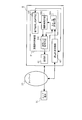
- a data transmission apparatus 11 that performs data transmission in response to an external request is provided connected to a network 20 such as the Internet.
- Reference numeral 30 denotes a user terminal (request source terminal) that acquires data relating to the request by transmitting a data acquisition request from a user or the like to the data transmission device 11 via the network 20, for example, a PC (Personal Computer) and portable terminals fall under this category. That is, the network 20 functions as a configuration that connects the user terminal 30 and the data transmission device 11.
- an origin server that holds data requested by a user for example, an origin server that holds data requested by a user, a cache server, a proxy server, an edge server, or the like is installed in the network 20 and data between the origin server and the user terminal 30
- a relay server device that terminates communication once, or a data communication device that constitutes the network 20 such as P-GW (Packet Data Network Gateway) or S-GW (Serving Gateway) can be adopted.
- the requested data is transmitted by establishing a connection such as TCP to the user terminal 30.
- an origin server may be arranged in the middle of a route for transmitting data to the user terminal 30.
- another network not shown
- an origin server for holding the requested data may be provided behind the data transmitting apparatus 11.
- the user terminal 30 transmits a data request to the data transmission device 11 or the origin server via the network 20, and in response to this, the data transmission device 11 or Data relating to the request is distributed from the origin server to the user terminal 30.
- the user terminal 30 is configured to present the data to the user or the like when the data is distributed.
- the data transmission apparatus 11 including the transmission unit 60 that transmits data to the user terminal 30 determines whether or not the increase in delay for data transmission is caused by network congestion based on a predetermined criterion.
- a transmission operation control unit 51 having a determination function for determining the transmission rate, and a transmission rate control function for controlling the operation of the transmission unit 60 so as not to decrease the transmission rate when the determination function determines that it is not caused by congestion, It has.
- the transmission operation control unit 51 that has determined that the delay has increased due to a cause other than congestion by analyzing the delay or the like related to data transmission controls the operation of the transmission unit 60 by adjusting the transmission rate. Inconvenience that the transmission rate is lowered in the case of an increase in delay due to reasons other than the above can be suppressed, thereby improving the throughput.
- the data transmission device 11 that transmits data requested via the network 20 to the user terminal 30 measures a delay related to packet transmission on the network 20 and measures the measured value (delay).
- a delay measurement processing unit 40 for storing and processing the statistical value and the network information subjected to statistical processing in an internal memory or the like (not shown), and an increase in delay stored by the delay measurement processing unit 40
- a transmission operation control unit 51 that determines whether or not it is caused by network congestion and that the transmission rate is not lowered when it is determined that it is not caused by congestion, and transmission preset in the user terminal 30
- a transmission unit 60 that transmits data according to the rate.
- the network information described above includes the transmission time of each packet, the data size of the transmission data, the transmission time of the acknowledgment packet from the user terminal 30 (time when the acknowledgment packet is returned), the time when the acknowledgment packet is received, the confirmation response
- the data size of the packet, the usable bandwidth of the network 20, the transmission throughput, and the like are included, and the delay measurement processing unit 40 acquires and stores the necessary information in the above measurement.
- the acknowledgment packet here refers to a so-called ACK (acknowledgment) packet, and is simply referred to as an acknowledgment in the following.
- the delay stored in the delay measurement processing unit 40, the statistical value obtained by performing statistical processing on the delay, and the network information are referred to as delay data.
- the delay measurement processing unit 40 measures a delay required for packet transmission / reception in the network 20 when the data transmission device 11 receives an acknowledgment of data (data packet) transmitted to the user terminal 30 or at certain time intervals. Configured to retrieve data.
- RTT Red Trip Time
- round trip delay unidirectional delay from the data transmission device 11 to the user terminal 30, and the like.
- an estimated value is obtained by a known method such as a method of measuring network information using transmission data or a method of transmitting and measuring a search packet separately from transmission data.
- a method of deriving may be adopted.
- the measurement method not only the measurement method but also other measurement methods may be employed.
- the transmission operation control unit 51 estimates (estimates) the queue amount indicating the amount of packets staying in the network 20 at the time of measurement based on the delay measured by the delay measurement processing unit 40, etc. 51A And a congestion detection unit 51B that detects (determines) the degree of congestion of the network 20 by comparing the queue amount estimated by the queue amount estimation unit 51A with a preset threshold (threshold for controlling the transmission unit).
- Transmission rate control means 51C for controlling the transmission rate of data to be transmitted to the user terminal 30 according to the degree of congestion detected by the congestion detection means 51B, and delay and network information stored in the delay measurement processing section 40 To detect the increase in delay and analyze the cause of the increase in delay and determine the threshold value based on the determination result.
- Has a reference value correcting means 51D for performing positive, the.
- the queue amount estimation unit 51A is set by the delay measured by the delay measurement processing unit 40 or the transmission rate control unit 51C when the delay measurement processing unit 40 measures the delay or at predetermined time intervals.
- the queue amount indicating the amount of packets staying in the network 20 is estimated based on the transmission rate or the like.
- the queue amount estimation unit 51A employs a configuration in which the delay measured by the delay measurement processing unit 40 immediately before the estimation process is used.
- the queue amount estimation means 51A estimates the queue amount.
- estimation method is not limited to the above-described equation 1, and for example, the estimation method using the current transmission rate (cw) set by the transmission rate control unit 51C instead of the transmission throughput (bw), An estimation method using delay (d) instead of ⁇ (d_min) may be adopted.
- the congestion detection unit 51B uses the queue amount estimated by the queue amount estimation unit 51A to estimate the degree of congestion in the network 20 when the queue amount estimation unit 51A estimates the queue amount or at predetermined time intervals. It is configured to detect.
- the congestion detection unit 51B employs a configuration in which the queue amount estimated by the queue amount estimation unit 51A immediately before the detection process is used.
- the congestion state is obtained when the queue amount (q) estimated by the queue amount estimation unit 51A exceeds a preset threshold value (th).
- th a preset threshold value
- the transmission rate control means 51C indicates the transmission rate (transmission speed) of data transmitted to the user terminal 30 when the congestion detection means 51B detects the degree of congestion or every predetermined time set in advance. It is configured to control based on the degree of congestion detected by 51B.
- the transmission rate control unit 51C employs a configuration in which the degree of congestion detected by the congestion detection unit 51B immediately before the transmission rate control is used.
- the transmission rate control means 51C reduces the transmission rate (cw) by a predetermined numerical value when the congestion detection means 51B detects that it is in a congestion state.
- a method of increasing the transmission rate (cw) by a predetermined numerical value when the congestion detection unit 51B detects that the congestion state is not present is adopted.
- a method in which control is performed such that the transmission rate (cw) is not changed depending on the congestion stage may be adopted in the above control method. That is, as described above, when the congestion detection unit 51B detects congestion in stages based on a plurality of preset thresholds, the amount of change in the transmission rate (cw) is changed for each congestion stage. You may take a method.
- control is performed to reduce the transmission rate (cw) only when the congestion detection means 51B detects that it is in a congestion state, and does not change the transmission rate (cw) when it is detected that the congestion detection means 51B is not in a congestion state. May be adopted.
- a control method using a predetermined ratio may be adopted instead of the predetermined numerical value used when increasing or decreasing the transmission rate (cw) in the above control method.
- a new transmission rate (cw) is calculated based on the current transmission rate (cw), the actual transmission throughput (bw) of data, and the degree of congestion (cn) detected by the congestion detection means 51B. You may take a method.
- the reference value correction processing unit 51D obtains a variation pattern of delay by analyzing the delay data stored and processed by the delay measurement processing unit 40 when the delay measurement processing unit 40 measures the delay or at regular time intervals. It is configured. Further, the reference value correction processing means 51D detects an increase in delay by comparing the delay variation pattern with a predetermined delay variation pattern and determines whether the delay increase has occurred (the delay increase is congested). Or whether it is due to another reason such as a bit error in the network 20).
- the delay increase is caused by a reason other than the congestion of the network 20.
- the method of determining the effect that the delay has increased due to reasons other than congestion is employed. That is, in the first embodiment, a phenomenon in which the arrival interval of packets to the user terminal 30 is extremely short is adopted as the delay variation pattern specified in advance.
- Pattern (phenomenon) that the user terminal 30 returns a confirmation response a pattern in which the time interval at which the user terminal 30 returns a confirmation response is very small, and “time interval at which the data transmission device 11 receives the confirmation response from the user terminal 30”
- a pattern in which the data size of the response is smaller than the value obtained by dividing the actual transmission throughput (bw) of the data by “the interval between transmission times of the confirmation response” is “the data size of the transmission data is divided by the available bandwidth of the network 20
- the pattern that is smaller than “value” or “interval of time when acknowledgment is received” is “use of data size of transmission data of network 20
- Reference value correcting means 51D where it was able to obtain a pattern, that is smaller than the value obtained by dividing "in-band is adopted a configuration in which a delay for reasons
- the reference value correction processing unit 51D temporarily corrects a parameter (congestion parameter) that affects the detection of the degree of congestion performed by the congestion detection unit 51B. It is configured.
- the congestion parameter includes a delay measured by the delay measurement processing unit 40, a threshold used when the congestion detection unit 51B detects the degree of congestion (a threshold for controlling the transmission unit 60), and a degree of congestion (cn). Point to.
- the threshold value (th) used by the congestion detection unit 51B is increased (temporarily) for a certain period of time as the correction method by the reference value correction processing unit 51D.
- Each of the above corrections is intended to control the transmission rate of data transmitted to the user terminal 30 so as not to decrease. Therefore, in the first embodiment, each correction is performed so that such control can be realized.
- the correction value is set in advance.
- the congestion detection unit 51B can execute the above detection process using the adjusted congestion parameter, and therefore, it is possible to suppress erroneous detection of congestion by the congestion detection unit 51B. It is possible to prevent excessive transmission rate lowering control by the transmission rate control means 51C.
- the data transmission device 11 acquires a data request message from the user terminal 30 via the intervening network 20, and according to this, the data related to the request is transmitted at the transmission rate set by the transmission rate control means 51C. A configuration of transmitting to the user terminal 30 is adopted.
- the data transmission device 11 since all the original data is held by itself, the data can be transmitted at the set transmission rate.
- the original data is copied in advance as a cache in its own storage area, or the data stream transmitted from the origin server is temporarily stored.
- the throughput of the network between the origin server and the data transmission device 11 the amount of data that can be processed within a certain time
- Data can be transmitted.
- the request message transmitted from the user terminal 30 to the origin server A router or the like installed in the route from the terminal 30 to the origin server and connected to the data transmission device 11 transfers the data to the data transmission device 11 instead of the origin server based on conditions such as header information of the request message. This method can be adopted.
- a method in which the user terminal 30 explicitly designates the data transmission device 11 as a proxy (proxy server) and transmits a data request message may be employed.
- the DNS or the like is connected to the data transmission device 11 instead of the origin server. You may make it employ
- the delay measurement processing unit 40 measures the delay required for packet transmission / reception in the network 20 and stores the acquired delay data. Storage processing is performed in a memory or the like (not shown) (FIG. 2: S201).
- the queue amount estimation unit 51A uses the delay measured by the delay measurement processing unit 40, the transmission rate set by the transmission rate control unit 51C, and the like.
- the queue amount indicating the packet amount staying in the network 20 is estimated.
- the queue amount estimation means 51A estimates the queue amount based on the above equation 1 (FIG. 2: S202).
- the congestion detection unit 51B detects the degree of congestion in the network 20 based on the estimated queue amount (FIG. 2: S203). .
- the congestion detection unit 51B detects that a congestion state exists when the queue amount estimated in real time exceeds a preset threshold. On the other hand, when the queue amount estimated in real time does not exceed a preset threshold value, the congestion detection unit 51B detects that there is no congestion state (FIG. 2: S203).
- the transmission rate control unit 51C uses the transmission rate of data transmitted to the user terminal 30 based on the degree of congestion detected by the congestion detection unit 51B ( (Transmission speed) is controlled (FIG. 2: S204).
- the transmission rate control means 51C reduces the transmission rate by a preset numerical value when the congestion detection means 51B detects that it is in a congestion state. On the other hand, when the congestion detection unit 51B detects that the congestion state is not present, the transmission rate control unit 51C increases the transmission rate by a preset numerical value (FIG. 2: S204).
- the delay measurement processing unit 40 measures the delay related to packet transmission in the network 20 and acquires the delayed data. Is stored in an internal memory or the like (not shown) (FIG. 3: S301).
- the reference value correction processing unit 51D determines that the delay has increased due to a cause other than congestion (FIG. 3: S302).
- the reference value correction processing unit 51D that determines that the delay has increased due to a cause other than congestion (FIG. 3: S302 / Yes), the delay measured by the delay measurement processing unit 40 or the congestion detection unit 51B indicates the degree of congestion.
- the threshold used for detection is corrected (FIG. 3: S303). Then, a determination process related to the subsequent data packet is executed.
- the reference value correction processing means 51D that has determined that the increase in delay is due to congestion of the network 20 (that delay has increased due to congestion) (FIG. 3: S302 / No), corrects the threshold value. Instead, the determination process related to the subsequent data packet is executed.
- the delay measurement processing (FIG. 2: S201) by the delay measurement processing unit 40 described above may be performed at predetermined time intervals.
- the queue amount estimation process (FIG. 2: S202) by the queue amount estimation unit 51A may be performed at predetermined time intervals. In this case, the queue amount estimation unit 51A uses the delay measured and stored by the delay measurement processing unit 40 immediately before the estimation process.
- the detection of the degree of congestion by the congestion detection means 51B (FIG. 2: S203) may be performed at predetermined time intervals. In this case, the congestion detection unit 51B uses the queue amount obtained by the queue amount estimation unit 51A in the estimation process immediately before the authorization.
- the transmission rate control by the transmission rate control means 51C (FIG. 2: S204) may be performed at predetermined time intervals. In this case, the transmission rate control means 51C uses information relating to the degree of congestion detected immediately before the congestion detection means 51B controls the transmission rate.
- the delay measurement processing by the delay measurement processing unit 40 may be performed at predetermined time intervals.
- the determination regarding the cause of the increase in delay by the reference value correction processing means 51D may be performed at predetermined time intervals.
- the reference value correction processing unit 51D uses the delay data obtained by the measurement process performed immediately before the determination by the delay measurement processing unit 40.
- each step in each of the above steps S201 to S204 (FIG. 2) and S301 to S303 (FIG. 3) may be programmed, and this series of control programs may be realized by a computer. .
- the threshold value that the congestion detection unit 51B refers to when detecting the degree of congestion of the network 20 is delayed due to reasons other than congestion. Since the reference value correction processing unit 51D determined to have increased is temporarily corrected, it prevents the transmission rate control unit 51C from unnecessarily lowering the transmission rate in the case of an increase in delay not caused by congestion. This makes it possible to improve the throughput.
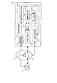
- the network 20 is configured to include a base station 20A that measures a radio wave intensity such as a radio wave intensity or a bit error in a wireless part of the network 20 or receives a radio wave from the user terminal 30. That is, the base station 20A is a data communication device that configures the network 20, such as eNodeB (LTE radio base station).
- a radio wave intensity such as a radio wave intensity or a bit error in a wireless part of the network 20 or receives a radio wave from the user terminal 30.
- the base station 20A is a data communication device that configures the network 20, such as eNodeB (LTE radio base station).
- the data transmission device 12 that performs data transmission processing in response to a request from the user terminal 30 includes each component (FIG. 2: delay measurement processing unit 40, queue amount estimation) of the data transmission device 11 according to the first embodiment described above.
- a radio wave state acquisition processing unit 70 for acquisition is provided.
- the data transmitting apparatus 12 has a configuration in which a transmission operation control unit 52 having a reference value correction processing unit 52D including the same function is used instead of the reference value correction processing unit 51D (FIG. 2). .
- the reference value correction processing unit 52D determines whether the cause of the increase in delay is a radio wave state acquisition processing unit. 70 has a characteristic functional configuration that is executed based on the radio wave condition index value acquired and stored in an internal memory or the like (not shown).
- the radio wave state acquisition processing unit 70 is configured to acquire an index of SINR (Signal toInterference plus Noise Ratio) measured by the user terminal 30 as the radio wave state index value. ing.
- SINR Signal toInterference plus Noise Ratio
- This SINR is an index representing the ratio of signal strength to noise and interference. The larger the value, the higher the signal strength and the less likely a bit error occurs.
- the radio wave condition acquisition processing unit 70 is not limited to the SINR index, but may acquire a radio wave condition index such as CQI (Channel Quality Indicator), RSSI (Received Signal Strength Indicator), or ASU (Arbitrary Strength Unit). It may be configured.
- CQI Channel Quality Indicator
- RSSI Receiveived Signal Strength Indicator
- ASU Automatic Strength Unit
- the CQI is an index proportional to SINR and represents the quality of the radio channel. A larger CQI value indicates a better quality (fewer errors).
- the RSSI or ASU is an index representing the strength of the signal received on the user terminal 30 side, and is an index reflected on the number of antennas of the mobile phone. Both of these values are characterized in that the larger the value, the higher the reception sensitivity (the error is less likely to occur).
- Each of the above-mentioned indicators represents the strength and quality of the signal, and has a correlation that the larger the value, the less likely an error occurs.
- the radio wave state acquisition processing unit 70 may be configured to acquire an index that an error is less likely to occur as the value is smaller.
- the reference value correction processing unit 52D is configured to execute the determination related to the cause of the increase in delay when the radio wave state acquisition processing unit 70 acquires the radio wave state index value or at predetermined time intervals. Has been.
- the reference value correction processing unit 52D employs a configuration in which the radio wave state acquisition processing unit 70 uses the radio wave state index value acquired immediately before the determination. .
- the radio wave condition index value exceeds a predetermined set value (threshold).
- a predetermined set value threshold
- the reference value correction processing means 52D increases the delay due to reasons other than congestion. The configuration of judging the effect was adopted.
- the use of the radio wave state index value acquired by the radio wave state acquisition processing unit 70 is not limited to the above-described determination method, and for example, in combination with the correction method described above, the radio wave state with respect to the delay measured by the delay measurement processing unit 40
- a method of correcting by adding (proportional) a value corresponding to the index value of the signal or a threshold value (threshold value for controlling the transmission unit 60) referred to when the congestion detection unit 51B estimates the degree of congestion A method of correcting by adding a value according to the value can be employed.
- the reference value correction processing unit 52D that determines that the delay has increased due to a cause other than congestion temporarily corrects a parameter (congestion parameter) that affects the detection of the degree of congestion performed by the congestion detection unit 51B. It is configured.
- the reference value correction processing unit 52D For example, a method of “correcting so that the delay (d) is decreased as the index value (x) is smaller” may be employed using the method shown in the following Expression 2 or 3.
- the reference value correction processing unit 52D is supplied with a method represented by, for example, the following formula 4 or formula 5. May be used to “correct so that the threshold value (th) increases as the index value (x) decreases”.
- a and b in the above formulas 1 to 4 are set values that can take either positive or negative values, and are set in advance before the execution of the correction processing by the reference value correction processing means 52D.
- the reference value correction processing unit 52D is configured to “correct so that the delay (d) decreases as the index value (x) increases”, or “the index value (x) is large.
- a configuration of “correcting so as to increase the threshold (th) as much as possible” may be employed.
- the radio wave state acquisition processing unit 70 acquires an index value of the radio wave state in the network 20 from the user terminal 30 or the base station 20A at regular intervals and stores it in an internal memory or the like (not shown) (FIG. 5: S501).
- the reference value correction processing unit 52D uses the radio wave state index value acquired by the radio wave state acquisition processing unit 70 in advance.
- the determination regarding the cause of the increase in delay is executed by comparing with the determined set value (FIG. 5: S502).
- the reference value correction processing means 52D that has determined that the delay has increased due to a cause other than congestion of the network 20 (FIG. 5: S502 / Yes), the delay measured by the delay measurement processing section 40 or the congestion detection means 51B The threshold value used when estimating the degree is temporarily corrected (FIG. 5: S503). Then, a determination process related to the subsequent data packet is executed.
- the reference value correction processing unit 52D that has determined that the delay has increased due to the congestion of the network 20 (FIG. 5: S502 / No) is a determination regarding the subsequent data packet without correcting the threshold value or the like. Execute the process.
- execution contents of the respective steps in the above steps S501 to S503 may be programmed, and the series of control programs may be realized by a computer.
- the reference value correction processing unit 52D that performs the determination regarding the cause of the increase in delay based on the fluctuation pattern of the delay of the network and the radio wave state in the wireless part is caused by the congestion.
- a configuration is adopted in which the congestion parameter used by the congestion detection means 51B is significantly corrected when it is determined that the delay is not increased. Therefore, when an increase in delay due to reasons other than congestion occurs, the detection processing based on the adjusted congestion parameter can be executed by the congestion detection means 51B, so that the transmission rate control means 51C transmits unnecessarily. The inconvenience of lowering the rate can be suppressed, thereby improving the throughput.
- the radio wave state acquisition processing unit 70 that acquires the radio wave state index value for the wireless portion of the network 20 from the user terminal 30 or the base station 20A at regular intervals functions effectively, and significant traffic is received. Since control can be realized, it is possible to prevent erroneous detection of congestion, thereby improving transmission efficiency.
- a data transmission device including a transmission unit for transmitting data to a user terminal, A determination function that determines whether or not the increase in delay in data transmission is due to network congestion based on a predetermined criterion, and this determination function transmits when it is determined that the increase is not due to congestion
- a data transmission device comprising: a transmission operation control unit having a transmission rate control function for controlling an operation of the transmission unit so as not to decrease a rate.
- the transmission operation control unit determines that it is not caused by congestion when a delay in the data transmission indicates a phenomenon in which the delay time increases sharply and then decreases in a line shape with respect to an increase in the transmission time of each packet.
- a data transmitting apparatus characterized by:
- the transmission operation control unit obtains a transmission time of an acknowledgment from the user terminal for transmission data, and an interval of the transmission time is smaller than a value obtained by dividing the data size of the transmission data by the available bandwidth of the network
- a data transmission device characterized by determining that it is not caused by congestion.
- the transmission operation control unit is not caused by congestion when an interval of time when an acknowledgment for transmission data is received from the user terminal is smaller than a value obtained by dividing the data size of the transmission data by the available bandwidth of the network.
- a data transmission device characterized by determining.
- a radio wave state acquisition processing unit that acquires a radio wave state index value in the wireless part of the network, The data transmission apparatus according to claim 1, wherein the transmission operation control unit performs the determination based on a magnitude relationship between the radio wave condition index value and a predetermined set value.
- a radio wave state acquisition processing unit that acquires a radio wave state index value in the wireless part of the network, The data transmission apparatus according to claim 1, wherein the transmission operation control unit determines that it is not caused by congestion when an index value of the radio wave state falls below a predetermined set value.
- a radio wave state acquisition processing unit that acquires a radio wave state index value in the wireless part of the network, The data transmission apparatus according to claim 1, wherein the transmission operation control unit determines that it is not caused by congestion when an index value of the radio wave condition exceeds a predetermined set value.
- a radio wave state acquisition processing unit that acquires a radio wave state index value in the wireless part of the network, The data transmission apparatus according to claim 1, wherein the transmission operation control unit determines that the signal is not caused by congestion when the radio wave condition index value is not within a predetermined setting range.
- the transmission operation control unit controls the operation of the transmission unit by performing correction that temporarily raises a threshold for control of the transmission unit when it is determined that the transmission operation control unit is not caused by congestion. apparatus.
- a delay measurement processing unit that measures the delay for the data transmission
- the transmission operation control unit controls the operation of the transmission unit by performing correction to temporarily reduce the delay measured by the delay measurement processing unit when it is determined that the transmission operation control unit is not caused by congestion.
- a delay measurement processing unit that measures the delay for the data transmission
- the transmission operation control unit controls the operation of the transmission unit by performing correction to temporarily reduce the delay measured by the delay measurement processing unit together with the correction when it is determined that the transmission operation control unit is not caused by congestion.
- the transmission operation control unit controls the operation of the transmission unit by performing correction by adding a value corresponding to (in proportion to) the index value of the radio wave state to a threshold value for controlling the transmission unit. Transmitter device.
- a delay measurement processing unit that measures the delay for the data transmission
- the transmission operation control unit controls the operation of the transmission unit by performing correction for subtracting a value corresponding to (in proportion to) the index value of the radio wave state from the delay measured by the delay measurement processing unit.
- a delay measurement processing unit that measures the delay for the data transmission
- the transmission operation control unit is configured to add a value corresponding to (in proportion to) the index value of the radio wave state to a threshold for control of the transmission unit, or from the delay measured by the delay measurement processing unit, the radio wave state index A data transmitting apparatus, wherein the operation of the transmitting unit is controlled by performing correction for subtracting a value corresponding to (proportional to) the value.
- a delay measurement processing unit that measures the delay for the data transmission
- the transmission operation control unit includes a correction for adding (proportional) a value corresponding to (in proportion to) the index value of the radio wave state to a threshold for control of the transmission unit, and the radio wave state index from the delay measured by the delay measurement processing unit.
- a data transmitting apparatus wherein the operation of the transmitting unit is controlled by performing correction for subtracting a value corresponding to (proportional to) the value.
- a data transmission device including a transmission unit for transmitting data to a user terminal, Determine whether or not the increase in delay for data transmission is due to network congestion based on pre-set criteria, Here, when it is determined that it is not caused by congestion, a preset detection criterion is corrected, Based on this corrected detection criteria, detect the degree of congestion, A data transmission method characterized in that the operation of the transmission unit is controlled so as not to lower the transmission rate in accordance with the detection result.
- a delay cause determination function for determining whether or not an increase in delay for data transmission is due to network congestion based on a predetermined criterion;
- a detection standard correction function that corrects a preset detection standard when it is determined that the delay cause determination function is not caused by congestion,
- a congestion detection function that detects the degree of congestion based on the detection standard corrected by this detection standard correction function,
- a data transmission program for causing a computer to realize a transmission rate control function for controlling the operation of the transmission unit so as not to lower the transmission rate according to the detection result by the congestion detection function.
- the present invention can be applied to an estimation device that estimates a network state such as the amount of queues (amount of staying packets), usable bandwidth, or bit error rate that is staying in the network from a delay. Further, the present invention can be applied to a transmission rate control apparatus that controls a transmission rate by simulating behavior equivalent to TCP in a protocol different from TCP such as UDP.
Abstract
Description
しかしながら、ビットエラーを再送によって回復するという技術内容であるため、上位層のプロトコルから見て遅延が発生するという不都合がある。
本発明は、上記従来関連例の有する不都合を改善するためのものであり、特に、ネットワークにおいて輻輳以外の理由に起因する遅延増加が生じても有効にスループット(伝送効率)を向上するデータ送信装置、データ送信方法、及びそのプログラムの提供を、その目的とする。
本発明の第1実施形態にかかるデータ送信装置を、図1及び図2に基づいて説明する。
まず、第1実施形態にかかるデータ送信装置の基本的な構成内容及びその周辺環境を、図1に基づいて説明する。
続いて、第1実施形態にかかるデータ送信装置の具体的な構成内容及びその周辺環境を、図1に基づいて説明する。
また、上記遅延計測処理部40にて記憶処理する遅延又はこれに統計処理を施した統計値等及び上記ネットワーク情報を遅延データと指称する。
次に、図1に示すデータ送信装置11の動作を、図2及び図3に示すフローチャートに基づいて説明する。まず、図1及び図2を参照して、データ送信装置11によるネットワーク遅延の計測処理からデータ送信のレート制御までの動作内容について説明する。
同様に、キュー量推測手段51Aによるキュー量の推測処理(図2:S202)は、予め設定された一定時間ごとに行うようにしてもよい。この場合、キュー量推測手段51Aは、当該推測処理の直前に遅延計測処理部40が計測すると共に記憶処理した遅延を使用する。
同じく、輻輳検知手段51Bによる輻輳の程度の検知(図2:S203)は、予め設定された一定時間ごとに行うようにしてもよい。この場合、輻輳検知手段51Bは、キュー量推測手段51Aが当該認定の直前の推測処理で得たキュー量を使用する。
同様に、送信レート制御手段51Cによる送信レートの制御(図2:S204)は、予め設定された一定時間ごとに行うようにしてもよい。この場合、送信レート制御手段51Cは、輻輳検知手段51Bが当該送信レートの制御直前に検知した輻輳の程度にかかる情報を使用する。
同様に、基準値補正処理手段51Dによる遅延増加の発生原因にかかる判定(図3:S302)は、予め設定された一定時間ごとに行うようにしてもよい。この場合、基準値補正処理手段51Dは、遅延計測処理部40が当該判定の直前に行った計測処理で得た遅延データを使用する。
本第1実施形態にかかるデータ送信装置11では、上述したように、輻輳検知手段51Bがネットワーク20の輻輳の程度を検知する際に参照する閾値等を、輻輳以外の理由に起因して遅延が増加した旨判定した基準値補正処理手段51Dが一時的に補正するという構成を採用したため、輻輳に起因しない遅延増加の場合に送信レート制御手段51Cが送出レートを不要に低下させてしまうことを防止でき、これにより、スループットの向上を図ることが可能となる。
次に、本発明の第2実施形態にかかるデータ送信装置を、図4及び図5に基づいて説明する。ここで、前述した第1実施形態と同一の構成部材については、同一の符号を用いるものとする。
ここでは、前述した第1実施形態にかかる構成内容とは異なる点を、図4に基づいて説明する。
上記RSSIやASUは、ユーザ端末30側で受信した信号の強度を表した指標で、携帯電話のアンテナ本数等に反映されている指標である。これらの値は共に、大きいほど受信感度が高い(エラーが起こりにくい)という特徴を有する。
ここで、当該判定を上記一定時間ごとに行う場合に基準値補正処理手段52Dは、電波状態取得処理部70が当該判定の直前に取得した電波状態の指標値を利用するという構成を採っている。
本第2実施形態では、指標値が小さいほどエラーが起こりやすい環境であるため、HARQによる再送・エラー修復が発生しやすく、これにより、輻輳に起因しない遅延増加が発生する可能性が高い。
次に、図5に示すデータ送信装置12の動作内容を説明する。
ここで、データ送信装置12によるネットワーク遅延の計測処理からデータ送信のレート制御までの動作内容については、第1実施形態において図2に則して説明したデータ送信装置11(図1)の動作内容(図2:S201~S204)と同様である。
本第2実施形態にかかるデータ送信装置12では、ネットワークの遅延の変動パターンや無線部分における電波状態をもとに遅延増加の発生原因にかかる判定を行う基準値補正処理手段52Dが、輻輳に起因しない遅延増加である旨判定した際に輻輳検知手段51Bが用いる輻輳パラメータを有意に補正するという構成を採用した。
したがって、輻輳以外の理由に起因する遅延増加が発生した場合には、調整された輻輳パラメータに基づく検知処理を輻輳検知手段51Bに実行させることができるため、送信レート制御手段51Cが不必要に送信レートを低下させるという不都合を抑制でき、これにより、スループットの向上を図ることが可能となる。
ユーザ端末にデータを送信する送信部を備えたデータ送信装置であって、
データ送信にかかる遅延の増加がネットワークの輻輳に起因するものであるか否かを予め設けられた基準に基づいて判定する判定機能と、この判定機能にて輻輳に起因しない旨判定した場合に送信レートを低下させないように前記送信部の動作を制御する送信レート制御機能と、を有する送信動作制御部、を備えたことを特徴とするデータ送信装置。
前記付記1に記載のデータ送信装置において、
前記送信動作制御部は、前記データ送信にかかる遅延が、急峻に増加したのちに各パケットの送出時刻の増加に対して線形状に減少していく現象を示す場合に、輻輳に起因しない旨判定することを特徴としたデータ送信装置。
前記付記1に記載のデータ送信装置において、
前記送信動作制御部は、送信データに対する前記ユーザ端末からの確認応答の送出時刻を取得すると共に、この送出時刻の間隔が当該送信データのデータサイズを前記ネットワークの可用帯域で割った値よりも小さい場合に、輻輳に起因しない旨判定することを特徴としたデータ送信装置。
前記付記1に記載のデータ送信装置において、
前記送信動作制御部は、送信データに対する確認応答を前記ユーザ端末から受信した時刻の間隔が当該送信データのデータサイズを前記ネットワークの可用帯域で割った値よりも小さい場合に、輻輳に起因しない旨判定することを特徴としたデータ送信装置。
前記付記1に記載のデータ送信装置において、
前記送信動作制御部は、送信データに対する確認応答を前記ユーザ端末から受信した時刻の間隔が当該確認応答のデータサイズを当該データ送信のスループットで割った値よりも小さいという変動パターンを得た場合に、輻輳に起因しない旨判定することを特徴としたデータ送信装置。
前記付記1に記載のデータ送信装置において、
さらに前記ネットワークの無線部分における電波状態の指標値を取得する電波状態取得処理部を備え、
前記送信動作制御部は、前記電波状態の指標値と予め決められた設定値の大小関係によって前記判定を行うことを特徴としたデータ送信装置。
前記付記1に記載のデータ送信装置において、
さらに前記ネットワークの無線部分における電波状態の指標値を取得する電波状態取得処理部を備え、
前記送信動作制御部は、前記電波状態の指標値が予め決められた設定値を下回った場合に輻輳に起因しない旨判定することを特徴としたデータ送信装置。
前記付記1に記載のデータ送信装置において、
さらに前記ネットワークの無線部分における電波状態の指標値を取得する電波状態取得処理部を備え、
前記送信動作制御部は、前記電波状態の指標値が予め決められた設定値を上回った場合に輻輳に起因しない旨判定することを特徴としたデータ送信装置。
前記付記1に記載のデータ送信装置において、
さらに前記ネットワークの無線部分における電波状態の指標値を取得する電波状態取得処理部を備え、
前記送信動作制御部は、前記電波状態の指標値が予め決められた設定範囲内に収まっていない場合に輻輳に起因しない旨判定することを特徴としたデータ送信装置。
前記付記1乃至9の何れか一つに記載のデータ送信装置において、
前記送信動作制御部は、輻輳に起因しない旨判定した際に、前記送信部の制御にかかる閾値を一時的に引き上げる補正を行うことにより前記送信部の動作を制御することを特徴としたデータ送信装置。
前記付記1乃至9の何れか一つに記載のデータ送信装置において、
さらに前記データ送信にかかる遅延を計測する遅延計測処理部を備え、
前記送信動作制御部は、輻輳に起因しない旨判定した際に、前記遅延計測処理部にて計測した遅延を一時的に減少させる補正を行うことにより前記送信部の動作を制御することを特徴としたデータ送信装置。
前記付記10に記載のデータ送信装置において、
さらに前記データ送信にかかる遅延を計測する遅延計測処理部を備え、
前記送信動作制御部は、輻輳に起因しない旨判定した際に、前記補正と共に前記遅延計測処理部にて計測した遅延を一時的に減少させる補正を行うことにより前記送信部の動作を制御することを特徴としたデータ送信装置。
前記付記6乃至9の何れか一つに記載のデータ送信装置において、
前記送信動作制御部は、前記送信部の制御にかかる閾値に前記電波状態の指標値に応じた(比例した)値を加える補正を行うことにより前記送信部の動作制御することを特徴としたデータ送信装置。
前記付記6乃至9の何れか一つに記載のデータ送信装置において、
さらに前記データ送信にかかる遅延を計測する遅延計測処理部を備え、
前記送信動作制御部は、前記遅延計測処理部にて計測した遅延から前記電波状態の指標値に応じた(比例した)値を減算する補正を行うことにより前記送信部の動作を制御することを特徴としたデータ送信装置。
前記付記6乃至9の何れか一つに記載のデータ送信装置において、
さらに前記データ送信にかかる遅延を計測する遅延計測処理部を備え、
前記送信動作制御部は、前記送信部の制御にかかる閾値に前記電波状態の指標値に応じた(比例した)値を加える補正又は前記遅延計測処理部にて計測した遅延から前記電波状態の指標値に応じた(比例した)値を減算する補正を行うことにより前記送信部の動作を制御することを特徴としたデータ送信装置。
前記付記6乃至9の何れか一つに記載のデータ送信装置において、
さらに前記データ送信にかかる遅延を計測する遅延計測処理部を備え、
前記送信動作制御部は、前記送信部の制御にかかる閾値に前記電波状態の指標値に応じた(比例した)値を加える補正及び前記遅延計測処理部にて計測した遅延から前記電波状態の指標値に応じた(比例した)値を減算する補正を行うことにより前記送信部の動作を制御することを特徴としたデータ送信装置。
ユーザ端末にデータを送信する送信部を備えたデータ送信装置にあって、
データ送信にかかる遅延の増加がネットワークの輻輳に起因するものであるか否かを予め設けられた基準に基づいて判定し、
ここで輻輳に起因しない旨判定した場合に予め設定された検知基準を補正し、
この補正された検知基準をもとに輻輳の程度を検知し、
この検知の結果にしたがって送信レートを低下させないように前記送信部の動作を制御することを特徴としたデータ送信方法。
ユーザ端末にデータを送信する送信部を備えたデータ送信装置にあって、
データ送信にかかる遅延の増加がネットワークの輻輳に起因するものであるか否かを予め設けられた基準に基づいて判定する遅延原因判定機能、
この遅延原因判定機能にて輻輳に起因しない旨判定した場合に予め設定された検知基準を補正する検知基準補正機能、
この検知基準補正機能にて補正された検知基準をもとに輻輳の程度を検知する輻輳検知機能、
この輻輳検知機能による検知の結果にしたがって送信レートを低下させないように前記送信部の動作を制御する送信レート制御機能、をコンピュータに実現させるためのデータ送信プログラム。
20 ネットワーク
20A 基地局
30 ユーザ端末
40 遅延計測処理部
51、52 送信動作制御部
51A キュー量推測手段
51B 輻輳検知手段
51C 送信レート制御手段
51D、52D 基準値補正処理手段
60 送信部
70 電波状態取得処理部
Claims (10)
- ユーザ端末にデータを送信する送信部を備えたデータ送信装置であって、
データ送信にかかる遅延の増加がネットワークの輻輳に起因するものであるか否かを予め設けられた基準に基づいて判定する判定機能と、この判定機能にて輻輳に起因しない旨判定した場合に送信レートを低下させないように前記送信部の動作を制御する送信レート制御機能と、を有する送信動作制御部、を備えたことを特徴とするデータ送信装置。 - 前記請求項1に記載のデータ送信装置において、
前記送信動作制御部は、前記データ送信にかかる遅延が、急峻に増加したのちに各パケットの送出時刻の増加に対して線形状に減少していく現象を示す場合に、輻輳に起因しない旨判定することを特徴としたデータ送信装置。 - 前記請求項1に記載のデータ送信装置において、
前記送信動作制御部は、送信データに対する前記ユーザ端末からの確認応答の送出時刻を取得すると共に、この送出時刻の間隔が当該送信データのデータサイズを前記ネットワークの可用帯域で割った値よりも小さい場合に、輻輳に起因しない旨判定することを特徴としたデータ送信装置。 - 前記請求項1に記載のデータ送信装置において、
前記送信動作制御部は、送信データに対する確認応答を前記ユーザ端末から受信した時刻の間隔が当該送信データのデータサイズを前記ネットワークの可用帯域で割った値よりも小さい場合に、輻輳に起因しない旨判定することを特徴としたデータ送信装置。 - 前記請求項1に記載のデータ送信装置において、
さらに前記ネットワークの無線部分における電波状態の指標値を取得する電波状態取得処理部を備え、
前記送信動作制御部は、前記電波状態の指標値と予め決められた設定値の大小関係によって前記判定を行うことを特徴としたデータ送信装置。 - 前記請求項1乃至5の何れか一つに記載のデータ送信装置において、
前記送信動作制御部は、輻輳に起因しない旨判定した際に、前記送信部の制御にかかる閾値を一時的に引き上げる補正を行うことにより前記送信部の動作を制御することを特徴としたデータ送信装置。 - 前記請求項1乃至5の何れか一つに記載のデータ送信装置において、
さらに前記データ送信にかかる遅延を計測する遅延計測処理部を備え、
前記送信動作制御部は、輻輳に起因しない旨判定した際に、前記遅延計測処理部にて計測した遅延を一時的に減少させる補正を行うことにより前記送信部の動作を制御することを特徴としたデータ送信装置。 - 前記請求項5に記載のデータ送信装置において、
さらに前記データ送信にかかる遅延を計測する遅延計測処理部を備え、
前記送信動作制御部は、前記送信部の制御にかかる閾値に前記電波状態の指標値に応じた値を加える補正又は前記遅延計測処理部にて計測した遅延から前記電波状態の指標値に応じた値を減算する補正を行うことにより前記送信部の動作を制御することを特徴としたデータ送信装置。 - ユーザ端末にデータを送信する送信部を備えたデータ送信装置にあって、
データ送信にかかる遅延の増加がネットワークの輻輳に起因するものであるか否かを予め設けられた基準に基づいて判定し、
ここで輻輳に起因しない旨判定した場合に予め設定された検知基準を補正し、
この補正された検知基準をもとに輻輳の程度を検知し、
この検知の結果にしたがって送信レートを低下させないように前記送信部の動作を制御することを特徴としたデータ送信方法。 - ユーザ端末にデータを送信する送信部を備えたデータ送信装置にあって、
データ送信にかかる遅延の増加がネットワークの輻輳に起因するものであるか否かを予め設けられた基準に基づいて判定する遅延原因判定機能、
この遅延原因判定機能にて輻輳に起因しない旨判定した場合に予め設定された検知基準を補正する検知基準補正機能、
この検知基準補正機能にて補正された検知基準をもとに輻輳の程度を検知する輻輳検知機能、
この輻輳検知機能による検知の結果にしたがって送信レートを低下させないように前記送信部の動作を制御する送信レート制御機能、をコンピュータに実現させるためのデータ送信プログラム。
Priority Applications (3)
| Application Number | Priority Date | Filing Date | Title |
|---|---|---|---|
| EP13864681.5A EP2938032B1 (en) | 2012-12-19 | 2013-12-17 | Data transmission device, data transmission method, and program therefor |
| JP2014553162A JP6274113B2 (ja) | 2012-12-19 | 2013-12-17 | データ送信装置、データ送信方法、及びそのプログラム |
| US14/653,333 US9860182B2 (en) | 2012-12-19 | 2013-12-17 | Data transmission device, data transmission method, and program therefor |
Applications Claiming Priority (2)
| Application Number | Priority Date | Filing Date | Title |
|---|---|---|---|
| JP2012-276440 | 2012-12-19 | ||
| JP2012276440 | 2012-12-19 |
Publications (1)
| Publication Number | Publication Date |
|---|---|
| WO2014098096A1 true WO2014098096A1 (ja) | 2014-06-26 |
Family
ID=50978423
Family Applications (1)
| Application Number | Title | Priority Date | Filing Date |
|---|---|---|---|
| PCT/JP2013/083797 WO2014098096A1 (ja) | 2012-12-19 | 2013-12-17 | データ送信装置、データ送信方法、及びそのプログラム |
Country Status (4)
| Country | Link |
|---|---|
| US (1) | US9860182B2 (ja) |
| EP (1) | EP2938032B1 (ja) |
| JP (1) | JP6274113B2 (ja) |
| WO (1) | WO2014098096A1 (ja) |
Cited By (4)
| Publication number | Priority date | Publication date | Assignee | Title |
|---|---|---|---|---|
| WO2017119408A1 (ja) * | 2016-01-07 | 2017-07-13 | 日本電気株式会社 | 送信データ量制御装置、方法および記録媒体 |
| CN108337180A (zh) * | 2017-01-19 | 2018-07-27 | 成都鼎桥通信技术有限公司 | 一种实现udp稳定速率灌包的方法 |
| WO2019004013A1 (ja) * | 2017-06-26 | 2019-01-03 | 日本電気株式会社 | データ送信装置、方法および記録媒体 |
| CN113098782A (zh) * | 2021-03-22 | 2021-07-09 | 武汉大学 | 一种网络拥塞的控制方法和计算机设备 |
Families Citing this family (5)
| Publication number | Priority date | Publication date | Assignee | Title |
|---|---|---|---|---|
| CN105227693B (zh) * | 2015-09-30 | 2019-04-05 | 青岛海信移动通信技术股份有限公司 | 一种移动设备的dns的配置方法和装置 |
| US9935888B2 (en) * | 2016-05-02 | 2018-04-03 | Visa International Service Association | System and method for latency-based queuing |
| US10129155B2 (en) * | 2016-11-21 | 2018-11-13 | Microsoft Technology Licensing, Llc | Delay based congestion control protocol co-existing with TCP |
| JP7015191B2 (ja) * | 2018-02-28 | 2022-02-02 | 株式会社Nttドコモ | 検知装置、検知システム及び検知プログラム |
| TWI758680B (zh) * | 2019-01-31 | 2022-03-21 | 日商日本電氣股份有限公司 | 資料中繼裝置、方法、發送系統及程式 |
Citations (2)
| Publication number | Priority date | Publication date | Assignee | Title |
|---|---|---|---|---|
| JP2001160824A (ja) | 1999-12-03 | 2001-06-12 | Mitsubishi Electric Corp | 有線無線混在網データ配信装置及びデータ配信方法 |
| JP2006005775A (ja) | 2004-06-18 | 2006-01-05 | Hewlett-Packard Development Co Lp | ネットワーク性能劣化原因判定方法及び輻輳制御方法 |
Family Cites Families (7)
| Publication number | Priority date | Publication date | Assignee | Title |
|---|---|---|---|---|
| EP1018821A1 (en) | 1999-01-08 | 2000-07-12 | TELEFONAKTIEBOLAGET L M ERICSSON (publ) | Communication device and method |
| JP4407700B2 (ja) * | 2007-02-02 | 2010-02-03 | 日本電気株式会社 | 通信端末、通信システム、輻輳制御方法、及び輻輳制御用プログラム |
| JP2009159192A (ja) | 2007-12-26 | 2009-07-16 | Sanyo Electric Co Ltd | 遠隔監視システム |
| JP2009278256A (ja) | 2008-05-13 | 2009-11-26 | Nec Corp | 中継装置および中継方法 |
| US20120063493A1 (en) * | 2009-03-06 | 2012-03-15 | Yohei Hasegawa | Transmission rate control method, transmission unit, and communication system |
| EP2586235B1 (en) | 2010-06-22 | 2018-10-10 | Telefonaktiebolaget LM Ericsson (publ) | Method and arrangement for detecting congestion in a communications network |
| US9924342B2 (en) * | 2015-06-16 | 2018-03-20 | Google Llc | Establishing a connection over a low power communication type |
-
2013
- 2013-12-17 JP JP2014553162A patent/JP6274113B2/ja active Active
- 2013-12-17 US US14/653,333 patent/US9860182B2/en active Active
- 2013-12-17 WO PCT/JP2013/083797 patent/WO2014098096A1/ja active Application Filing
- 2013-12-17 EP EP13864681.5A patent/EP2938032B1/en active Active
Patent Citations (2)
| Publication number | Priority date | Publication date | Assignee | Title |
|---|---|---|---|---|
| JP2001160824A (ja) | 1999-12-03 | 2001-06-12 | Mitsubishi Electric Corp | 有線無線混在網データ配信装置及びデータ配信方法 |
| JP2006005775A (ja) | 2004-06-18 | 2006-01-05 | Hewlett-Packard Development Co Lp | ネットワーク性能劣化原因判定方法及び輻輳制御方法 |
Non-Patent Citations (4)
| Title |
|---|
| C. JIN; D. WEI; S. LOW: "FAST TCP: Motivation, Architecture, Algorithms, Performance", PROC. OF IEEE INFOCOM, March 2004 (2004-03-01) |
| GO HASEGAWA: "Research Trends on TCP Congestion Control Mechanisms", THE TRANSACTIONS OF THE INSTITUTE OF ELECTRONICS, INFORMATION AND COMMUNICATION ENGINEERS, vol. J94-B, 1 May 2011 (2011-05-01), pages 663 - 672, XP055258212 * |
| L.S. BRAKMO; S. O'MALLEY; L.L. PETERSON: "TCP Vegas: New Techniques for Congestion Detection and Avoidance", COMPUTER COMMUNICATION REVIEW, vol. 24, no. 4, October 1994 (1994-10-01), pages 24 - 35 |
| See also references of EP2938032A4 |
Cited By (7)
| Publication number | Priority date | Publication date | Assignee | Title |
|---|---|---|---|---|
| WO2017119408A1 (ja) * | 2016-01-07 | 2017-07-13 | 日本電気株式会社 | 送信データ量制御装置、方法および記録媒体 |
| US10911359B2 (en) | 2016-01-07 | 2021-02-02 | Nec Corporation | Transmit data volume control device, method, and recording medium |
| CN108337180A (zh) * | 2017-01-19 | 2018-07-27 | 成都鼎桥通信技术有限公司 | 一种实现udp稳定速率灌包的方法 |
| WO2019004013A1 (ja) * | 2017-06-26 | 2019-01-03 | 日本電気株式会社 | データ送信装置、方法および記録媒体 |
| US11184803B2 (en) | 2017-06-26 | 2021-11-23 | Nec Corporation | Data transmission device, method and recording medium |
| CN113098782A (zh) * | 2021-03-22 | 2021-07-09 | 武汉大学 | 一种网络拥塞的控制方法和计算机设备 |
| CN113098782B (zh) * | 2021-03-22 | 2022-08-30 | 武汉大学 | 一种网络拥塞的控制方法和计算机设备 |
Also Published As
| Publication number | Publication date |
|---|---|
| EP2938032A4 (en) | 2016-07-20 |
| US20150350097A1 (en) | 2015-12-03 |
| EP2938032A1 (en) | 2015-10-28 |
| JPWO2014098096A1 (ja) | 2017-01-12 |
| US9860182B2 (en) | 2018-01-02 |
| EP2938032B1 (en) | 2019-04-24 |
| JP6274113B2 (ja) | 2018-02-07 |
Similar Documents
| Publication | Publication Date | Title |
|---|---|---|
| JP6274113B2 (ja) | データ送信装置、データ送信方法、及びそのプログラム | |
| US9842013B2 (en) | Dynamic adaptive approach for failure detection of node in a cluster | |
| US10911359B2 (en) | Transmit data volume control device, method, and recording medium | |
| KR102350504B1 (ko) | 통신 시스템에서 하향링크 전송률 제어를 위한 장치 및 방법 | |
| JP2018504050A (ja) | トラフィックフローの監視 | |
| US9456377B2 (en) | System and method for transmission control protocol service delivery in wireless communications systems | |
| US9167473B2 (en) | Communication processing method, apparatus and gateway device | |
| US9674101B2 (en) | Communication device, transmission data output control method, and program for same | |
| US20150189659A1 (en) | Method and a device for low intrusive fast estimation of the bandwidth available between two ip nodes | |
| EP2706695A2 (en) | Wireless communication system, base station, and wireless communication method | |
| KR101527826B1 (ko) | 데이터 전송 방법, 장치, 및 시스템 | |
| US11115305B2 (en) | Mobile radio network node and method for estimating a capacity of a link in a radio communications network | |
| JP2008104018A (ja) | 通信システム、通信装置、及び送信制御方法 | |
| WO2014171543A1 (ja) | データ送信装置、データ送信方法、及びそのプログラム | |
| JP6418169B2 (ja) | 遅延最小値算出装置、情報送信装置、遅延最小値算出方法およびコンピュータプログラム | |
| WO2019124290A1 (ja) | 送信データ量制御装置、方法および記録媒体 | |
| JP6897769B2 (ja) | データ送信装置、方法およびプログラム | |
| JP6459590B2 (ja) | 通信装置、通信方法、および通信プログラム | |
| JP6668961B2 (ja) | 通信装置、方法およびプログラム | |
| Osuga et al. | A method for correcting minimum RTT of TCP congestion control in mobile networks | |
| JP6544353B2 (ja) | 送信データ量制御装置、制御システム、制御方法および制御プログラム | |
| JP5923012B2 (ja) | 中継装置及び中継方法 | |
| Mahapatra et al. | RCM-BR: An efficient rate control protocol for multimedia delivery in Wireless Internet |
Legal Events
| Date | Code | Title | Description |
|---|---|---|---|
| 121 | Ep: the epo has been informed by wipo that ep was designated in this application |
Ref document number: 13864681 Country of ref document: EP Kind code of ref document: A1 |
|
| ENP | Entry into the national phase |
Ref document number: 2014553162 Country of ref document: JP Kind code of ref document: A |
|
| WWE | Wipo information: entry into national phase |
Ref document number: 2013864681 Country of ref document: EP |
|
| WWE | Wipo information: entry into national phase |
Ref document number: 14653333 Country of ref document: US |
|
| NENP | Non-entry into the national phase |
Ref country code: DE |