WO2014098003A1 - 車載器、通信方法及び記録媒体 - Google Patents
車載器、通信方法及び記録媒体 Download PDFInfo
- Publication number
- WO2014098003A1 WO2014098003A1 PCT/JP2013/083543 JP2013083543W WO2014098003A1 WO 2014098003 A1 WO2014098003 A1 WO 2014098003A1 JP 2013083543 W JP2013083543 W JP 2013083543W WO 2014098003 A1 WO2014098003 A1 WO 2014098003A1
- Authority
- WO
- WIPO (PCT)
- Prior art keywords
- communication
- service
- vehicle
- communication unit
- antenna
- Prior art date
- Legal status (The legal status is an assumption and is not a legal conclusion. Google has not performed a legal analysis and makes no representation as to the accuracy of the status listed.)
- Ceased
Links
Images




Classifications
-
- H—ELECTRICITY
- H04—ELECTRIC COMMUNICATION TECHNIQUE
- H04B—TRANSMISSION
- H04B7/00—Radio transmission systems, i.e. using radiation field
- H04B7/02—Diversity systems; Multi-antenna system, i.e. transmission or reception using multiple antennas
- H04B7/04—Diversity systems; Multi-antenna system, i.e. transmission or reception using multiple antennas using two or more spaced independent antennas
- H04B7/0404—Diversity systems; Multi-antenna system, i.e. transmission or reception using multiple antennas using two or more spaced independent antennas the mobile station comprising multiple antennas, e.g. to provide uplink diversity
-
- H—ELECTRICITY
- H04—ELECTRIC COMMUNICATION TECHNIQUE
- H04M—TELEPHONIC COMMUNICATION
- H04M15/00—Arrangements for metering, time-control or time indication ; Metering, charging or billing arrangements for voice wireline or wireless communications, e.g. VoIP
- H04M15/61—Arrangements for metering, time-control or time indication ; Metering, charging or billing arrangements for voice wireline or wireless communications, e.g. VoIP based on the service used
-
- H—ELECTRICITY
- H04—ELECTRIC COMMUNICATION TECHNIQUE
- H04M—TELEPHONIC COMMUNICATION
- H04M15/00—Arrangements for metering, time-control or time indication ; Metering, charging or billing arrangements for voice wireline or wireless communications, e.g. VoIP
- H04M15/68—Payment of value-added services
-
- H—ELECTRICITY
- H04—ELECTRIC COMMUNICATION TECHNIQUE
- H04M—TELEPHONIC COMMUNICATION
- H04M15/00—Arrangements for metering, time-control or time indication ; Metering, charging or billing arrangements for voice wireline or wireless communications, e.g. VoIP
- H04M15/83—Notification aspects
-
- H—ELECTRICITY
- H04—ELECTRIC COMMUNICATION TECHNIQUE
- H04W—WIRELESS COMMUNICATION NETWORKS
- H04W4/00—Services specially adapted for wireless communication networks; Facilities therefor
-
- H—ELECTRICITY
- H04—ELECTRIC COMMUNICATION TECHNIQUE
- H04W—WIRELESS COMMUNICATION NETWORKS
- H04W4/00—Services specially adapted for wireless communication networks; Facilities therefor
- H04W4/24—Accounting or billing
-
- H—ELECTRICITY
- H04—ELECTRIC COMMUNICATION TECHNIQUE
- H04W—WIRELESS COMMUNICATION NETWORKS
- H04W4/00—Services specially adapted for wireless communication networks; Facilities therefor
- H04W4/30—Services specially adapted for particular environments, situations or purposes
- H04W4/40—Services specially adapted for particular environments, situations or purposes for vehicles, e.g. vehicle-to-pedestrians [V2P]
- H04W4/48—Services specially adapted for particular environments, situations or purposes for vehicles, e.g. vehicle-to-pedestrians [V2P] for in-vehicle communication
Definitions
- the present invention relates to a vehicle-mounted device, a communication method, and a recording medium, and more particularly, to a vehicle-mounted device, a communication method, and a recording medium used in a communication system configured to provide a plurality of services to a vehicle-mounted device mounted on a vehicle.
- a vehicle-mounted device a communication method, and a recording medium used in a communication system configured to provide a plurality of services to a vehicle-mounted device mounted on a vehicle.
- Recent on-board devices are required to support multiple services. For example, it is required that the vehicle-mounted device is compatible with both road-to-vehicle communication and vehicle-to-vehicle communication, and that the vehicle-mounted device is compatible with both a traffic information service and a billing service.
- An on-vehicle device that supports both road-to-vehicle communication and vehicle-to-vehicle communication is disclosed in, for example, Patent Document 1 (Japanese Patent Laid-Open No. 2008-99085).
- the vehicle-mounted device disclosed in Patent Document 1 has two antennas for performing diversity, and the two antennas are either a road-to-vehicle communication transceiver or a vehicle-to-vehicle communication transceiver by a switch. It has the structure connected to.
- diversity refers to communication quality using the signal of the other communication path even if the signal of one communication path deteriorates by using multiple highly independent communication paths. It is a technology to ensure.
- WAVE wireless access in vehicular environment
- WAVE is a revision of IEEE802.11, which is a wireless LAN standard, for mobile units, and uses IEEE802.11p in layer 1 (physical layer) and layer 2 (data link layer).
- DCF autonomous distributed control
- each communication frame is divided into a plurality of time slots called “channels”.
- Each communication frame includes a single control channel and at least one service channel. Broadcast communication is performed on the control channel, and communication for transmitting data to a specific transmission destination is performed on the service channel.
- a transmission source communication terminal that desires transmission designates a transmission destination communication terminal and a service channel through which transmission is performed in the control channel.
- the destination communication terminal receives data from the source communication terminal on the designated service channel.
- One problem in providing multiple services is that the communication speed and reliability required for multiple services may differ. For example, in a traffic information service, it is required to communicate a large amount of data, but the required reliability is relatively low. On the other hand, in the billing service, a small amount of information that can be communicated is allowed, but communication with high reliability is required.
- an object of the present invention is to optimize a switching procedure between a plurality of services having different required reliability.
- the present invention provides a technique for smoothly switching between a plurality of services in an in-vehicle device that includes two antennas and supports diversity.
- the vehicle-mounted device includes a first antenna and a second antenna, a first service communication unit corresponding to the first service, and a second service communication unit corresponding to the second service.
- a switch for switching a connection relationship between the first antenna and the second antenna, the first service communication unit and the second service communication unit, and a control unit for controlling the switch.
- the first service communication unit is configured to perform communication for the first service with an external first communication device at a communication speed within the first communication speed range
- the second service communication unit It is configured to perform communication for the second service with an external second communication device at a communication speed within a range of two communication speeds.
- the first communication speed range is different from the second communication speed range.
- the on-vehicle device has first to third operation modes.
- the switch connects both the first antenna and the second antenna to the first service communication unit, and the first service communication unit is within the first communication speed range. Communication for the first service is performed with the first communication device at the communication speed. If the first service communication unit detects that the wireless signal for communication of the second service is received from the second communication device when the on-vehicle device is set to the first operation mode, the on-vehicle device performs the second operation. Enter mode.
- the switch When the vehicle-mounted device is set to the second operation mode, the switch connects one of the first antenna and the second antenna to the first service communication unit, connects the other to the second service communication unit, and The communication unit performs communication for the first service with the first communication device at a communication speed within the first communication speed range, and the second service communication unit performs the second communication with the communication speed within the second communication speed range. Communication with the communication device for the second service is performed.
- the on-vehicle device When the on-vehicle device is set to the second operation mode and the control unit completes the disconnection process for disconnecting the communication for the first service, the on-vehicle device shifts to the third operation mode.
- the switch connects both the first antenna and the second antenna to the second service communication unit, and the second service communication unit is within the second communication speed range. Communication for the second service is performed with the second communication device at the communication speed.
- the upper limit value of the second communication speed range is lower than the upper limit value of the first communication speed range.
- the first service is a traffic information service that provides traffic information to the vehicle-mounted device
- the second service is a billing service that electronically processes a fee imposed on the user of the vehicle-mounted device. .
- the first service communication unit When the vehicle-mounted device is set to the first operation mode, the first service communication unit performs communication for the first service with the first communication device while performing diversity using the first antenna and the second antenna. It is preferable.
- the second service communication unit when the vehicle-mounted device is set in the third operation mode, performs diversity for the second communication device and the second service while performing diversity using the first antenna and the second antenna. It is preferable to perform communication.
- a first antenna and a second antenna a first service communication unit corresponding to a first service, a second service communication unit corresponding to a second service, a first antenna and a second antenna.
- an on-vehicle device communication method including a switch that switches a connection relationship between the first service communication unit and the second service communication unit.
- the first service communication unit is configured to perform communication for the first service with an external first communication device at a communication speed within the first communication speed range
- the second service communication unit includes: It is configured to perform communication for the second service with an external second communication device at a communication speed within the second communication speed range.
- the first communication speed range is different from the second communication speed range.
- the communication method is When the vehicle-mounted device is set to the first operation mode, the first service communication unit connects the first antenna and the second antenna to the first service communication unit and is within the first communication speed range. Communicating for the first service with the first communication device at a communication speed of: When the on-vehicle device is set to the first operation mode and detects that the first service communication unit has received a radio signal for communication of the second service from the second communication device, the on-vehicle device is set to the second operation mode. The steps to transition to When the vehicle-mounted device is set to the second operation mode, the switch connects one of the first antenna and the second antenna to the first service communication unit and connects the other to the second service communication unit.
- the first service communication unit performs communication for the first service with the first communication device at a communication speed within the first communication speed range, and the second service communication unit performs the second communication at a communication speed within the second communication speed range.
- Communicating with the device for a second service When the on-vehicle device is set to the second operation mode, the control unit performs a disconnection process for disconnecting the communication for the first service; After completing the cutting process, the step of shifting the vehicle-mounted device to the third operation mode; When the vehicle-mounted device is set to the third operation mode, the second service communication unit within the second communication speed range with both the first antenna and the second antenna connected to the second service communication unit by the switch. Performing communication for the second service with the second communication device at the communication speed.
- the program causes the arithmetic device mounted on the vehicle-mounted device to execute the communication method described above.
- the program may be recorded on a recording medium.
- the present invention it is possible to smoothly switch between the first service and the second service having different required reliability, and the reliability when each of the first service and the second service is performed is also improved. Can be made.
- FIG. 1 is a conceptual diagram showing a configuration of a communication system 10 according to an embodiment of the present invention.
- the communication system 10 includes a traffic information service center 1, a billing service center 2, roadside communication devices 3 and 4, and an in-vehicle device 6 mounted on the vehicle 5.
- a communicable region of each roadside communication device 3 (that is, a region where each roadside communication device 3 can communicate with the vehicle-mounted device 6) is indicated by reference numeral 3 a, and a communicable region of each roadside communication device 4.
- the traffic information service center 1 is a host computer having a function of collecting and providing data necessary for providing the traffic information service.
- the billing service center 2 is a host computer that has a function of collecting and providing data necessary for provision of billing services.
- the communication system 10 is configured to provide two services based on road-to-vehicle communication: a traffic information service and a billing service.
- the traffic information service is a service that provides various information related to traffic to the vehicle-mounted device 6 (and devices connected to the vehicle-mounted device 6).
- the billing service is a service for electronically processing a fee (for example, a toll on a toll road or a parking fee) imposed on the user of the vehicle 5 on which the vehicle-mounted device 6 is mounted.
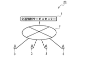
- the traffic information service center 1 and the roadside communication device 3 are connected by a communication network 7 to constitute a traffic information service network 20 that provides a traffic information service.
- the traffic information service network 20 is a network for providing the traffic information service to the vehicle-mounted device 6 (and devices connected thereto).
- the traffic information service center 1 provides various information related to traffic to the vehicle-mounted device 6 via the roadside communication device 3. Examples of information provided to the vehicle-mounted device 6 in the traffic information service include traffic jam information, emergency vehicle approach information, accident information, weather information, traffic regulation information, advertisement information, and news information.
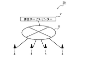
- the billing service center 2 and the roadside communication device 4 are connected by a communication network 8 to constitute a billing service network 30 that provides a billing service.
- the billing service network 30 is a network for providing a billing service to the vehicle-mounted device 6 (and devices connected thereto).
- the billing service center 2 and the vehicle-mounted device 6 send various information necessary for billing processing to be charged to the user of the vehicle 5 equipped with the vehicle-mounted device 6 via the roadside communication device 4. Exchange.
- Examples of information exchanged between the billing service center 2 and the vehicle-mounted device 6 in the billing service include vehicle type information (for example, information indicating whether the vehicle 5 is a normal vehicle, a large vehicle, or a motorcycle), Billing card information (card type and card number of the card inserted into the vehicle-mounted device 6) and billing history information (billing history such as billing start) are listed.
- vehicle type information for example, information indicating whether the vehicle 5 is a normal vehicle, a large vehicle, or a motorcycle
- Billing card information card type and card number of the card inserted into the vehicle-mounted device 6)
- billing history information billing history such as billing start
- the traffic information service provided by the traffic information service center 1 and the roadside communication device 3 is a service (wide area service) provided in a relatively wide area, whereas a charging service is provided.
- the billing service provided by the center 2 and the roadside communication device 4 is a service (local service) provided in a limited area.
- the onboard equipment 6 is normally set to the traffic information service mode which receives provision of a traffic information service.
- the vehicle-mounted device 6 is switched to the billing service mode in which billing service is provided.
- one feature of the communication system of the present embodiment is that, when the traffic information service mode is shifted to the billing service mode, the traffic information service and the billing service are once provided in parallel in the switching communication mode. It is to be switched. A procedure for switching between the traffic information service mode, the billing service mode, and the switching communication mode will be described in detail later.
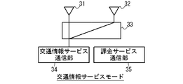
- FIG. 3 is a block diagram showing a configuration of the vehicle-mounted device 6 in the present embodiment.
- the vehicle-mounted device 6 includes two antennas 31 and 32, a switch 33, a traffic information service communication unit 34, a billing service communication unit 35, a calculation device 36, and a storage device 37.
- Each of the two antennas 31 and 32 has a function of transmitting and receiving radio signals to and from the roadside communication devices 3 and 4.
- the vehicle-mounted device 6 is configured to perform diversity using the two antennas 31 and 32.
- the switch 33 has a function of switching the connection relationship between the antennas 31 and 32 and the traffic information service communication unit 34 and the billing service communication unit 35.
- the switch 33 is configured to be capable of at least the following three states: (1) Both antennas 31 and 32 are connected to the traffic information service communication unit 34 (2) One of the antennas 31 and 32 is connected to the traffic information service communication unit 34 and the other is connected to the billing service communication unit 35 State (3) State in which both antennas 31 and 32 are connected to charging service communication unit 35 Switch 33 performs switching between these three states. Control of the operation of the switch 33 is performed in response to a control signal 38 sent from the arithmetic device 36 in accordance with the operation mode in which the vehicle-mounted device 6 is set.
- the traffic information service communication unit 34 is configured to be able to communicate with the roadside communication device 3 used for communication for the traffic information service, and is a radio circuit for transmitting and receiving radio signals to and from the roadside communication device 3. It has.
- the traffic information service communication unit 34 modulates data (traffic information service transmission data) sent from the computing device 36 in relation to the traffic information service, and generates a radio signal to be transmitted to the roadside communication device 3.
- the traffic information service communication unit 34 demodulates the radio signal received from the roadside communication device 3 to generate traffic information service reception data, and sends the traffic information service reception data to the arithmetic device 36.
- the billing service communication unit 35 is configured to be able to communicate with the roadside communication device 4 used for billing service communication, and is a radio circuit for transmitting and receiving radio signals to and from the roadside communication device 4. It has.
- the billing service communication unit 35 modulates billing service transmission data sent from the arithmetic device 36 in relation to the billing service and generates a radio signal to be transmitted to the roadside communication device 3.
- the traffic information service communication unit 34 demodulates the radio signal received from the roadside communication device 3 to generate billing service reception data, and sends the billing service reception data to the arithmetic device 36.
- the computing device 36 has the following three functions. First, the computing device 36 has a traffic information service data processing function 41 for processing data related to the traffic information service. In the traffic information service data processing function 41, the traffic information service reception data received from the traffic information service communication unit 34 is processed, and traffic information service transmission data is generated and supplied to the traffic information service communication unit 34. In the processing in the traffic information service data processing function 41, necessary information is stored in the storage device 37 as traffic information service data 44. Further, display data to be displayed on the display device 9 connected to the vehicle-mounted device 6 is generated by the processing in the traffic information service data processing function 41. The display data includes various traffic information (for example, traffic jam information, emergency vehicle approach information, accident information, weather information, traffic regulation information, advertisement information and news information), and the user looks at the display device 9. You can know various traffic information.
- the display device 9 may be an external device such as a car navigation system, or may be a display device dedicated to the vehicle-mounted device 6.
- the computing device 36 has a billing service data processing function 42 for processing data related to the billing service.
- the billing service data processing function 42 processes billing service reception data received from the billing service communication unit 35, generates billing service transmission data, and supplies the billing service transmission data to the billing service communication unit 35.
- necessary information is stored in the storage device 37 as billing service data 45.
- the arithmetic device 36 has a communication switching control function 43 that switches the operation mode of the vehicle-mounted device 6.
- the vehicle-mounted device 6 has three operation modes: a traffic information service mode, a billing service mode, and a switching communication mode.
- the communication switching control function 43 selects between these operation modes, and further generates a control signal 38 for controlling the switch 33 in accordance with the selection of the operation mode.
- Each function of the arithmetic device 36 may be realized by the arithmetic device 36 executing a software program stored in the storage device 37.
- the program may be installed in the storage device 37 using a recording medium that records the program.
- communication for the traffic information service performed between the traffic information service communication unit 34 and the roadside communication device 3 and charging performed between the billing service communication unit 35 and the roadside communication device 4 are performed.
- the communication speed required for service and the reliability are different. Specifically, communication for a traffic information service is required to have a high communication speed, but communication with relatively low reliability is allowed. On the other hand, communication for billing service is allowed to be slow in communication speed, but communication with high reliability is required.
- each of the traffic information service communication unit 34 and the billing service communication unit 35 is configured to monitor a BER (bit error rate) of communication performed by the traffic information service communication unit 34 and the billing service communication unit 35 and switch the communication speed according to the BER.
- the upper limit value of the communication speed range used in the communication for the billing service is set lower than the upper limit value of the communication speed range used in the communication for the traffic information service.
- the vehicle-mounted device 6 of the present embodiment has three operation modes: a traffic information service mode, a switching communication mode, and a billing service mode.
- the switch 33 responds to the control signal 38 supplied from the arithmetic device 36 to the antennas 31 and 32. Both are connected to the traffic information service communication unit 34.
- the traffic information service communication unit 34 performs communication for the traffic information service using both the antennas 31 and 32.
- the traffic information service communication unit 34 performs diversity using the two antennas 31 and 32. In diversity using the antennas 31 and 32, at least one of transmission diversity and reception diversity is performed. In diversity, any of spatial diversity, polarization diversity, and angle diversity may be performed. By performing diversity, it is possible to improve the reliability of communication for the traffic information service.
- the switch 33 connects one of the antennas 31 and 32 to the traffic information service communication unit 34 and the other to the billing service. Connect to the communication unit 35.
- the traffic information service communication unit 34 performs communication for the traffic information service using the one antenna
- the charging service communication unit 35 performs communication for the charging service using the other antenna.
- the switch 33 connects both the antennas 31 and 32 to the charging service communication unit 35.
- the charging service communication unit 35 performs communication for charging service using both the antennas 31 and 32.
- the billing service communication unit 35 performs diversity using the two antennas 31 and 32.
- the allowable range of the communication speed is different between the traffic information service communication and the billing service communication. That is. This is because even if the vehicle 5 equipped with the vehicle-mounted device 6 enters the billing area (that is, the communicable region 4a of the roadside communication device 4) when the vehicle-mounted device 6 is set to the traffic information service mode, the traffic information
- the service communication unit 34 causes a situation in which a communication radio signal for billing service sent from the roadside communication device 4 cannot be normally received (that is, cannot be demodulated normally). However, it can be detected that a radio signal is input from the roadside communication device 4 itself.
- the traffic information service communication unit 34 when the traffic information service communication unit 34 detects that a radio signal is input from the roadside communication device 4, the traffic information service communication unit 34 notifies the arithmetic device 36 to that effect.
- the computing device 36 switches the vehicle-mounted device 6 to the switching communication mode when notified from the traffic information service communication unit 34 that a radio signal has been input from the roadside communication device 4. Thereby, the vehicle-mounted device 6 is in a state in which the billing service communication unit 35 can perform communication for the billing service while the traffic information service communication unit 34 continues the communication for the traffic information service.
- the traffic information service data processing function 41 of the computing device 36 performs a disconnection process for normally stopping the traffic information service (for example, the vehicle-mounted device 6 is a traffic information service). Data indicating that the reception of the data related to the transmission is terminated from the vehicle-mounted device 6 to the traffic information service center 1). After the cutting process is completed, the arithmetic device 36 switches the vehicle-mounted device 6 to the billing service mode. Thereby, only communication for the billing service is performed thereafter.
- the operation mode of the vehicle-mounted device 6 is switched from the traffic information service to the billing service mode via the switching communication mode, thereby ensuring a long communication time in the traffic information service mode and a communicable time in the billing service mode. be able to.
- the billing service mode By ensuring a long communicable time in the traffic information service mode, it is possible to reliably disconnect the traffic information service and suppress unnecessary data retransmission. Further, by ensuring a long communication possible time in the billing service mode, the billing service can be reliably provided.
- the reliability of communication in each operation mode can be further improved.
- FIG. 5 is a diagram for explaining an example of the operation of the vehicle-mounted device 6 according to the present embodiment, in particular, the operation of the vehicle-mounted device 6 when the vehicle-mounted device 6 shifts from the traffic information service mode to the billing service mode through the switching communication mode. is there.
- FIG. 5 shows an operation example in which communication between the roadside communication devices 3 and 4 and the vehicle-mounted device 6 mounted on the vehicle 5 is performed according to the WAVE communication standard.
- each communication frame includes a single control channel and at least one service channel. Broadcast communication is performed on the control channel, and communication for transmitting data to a specific transmission destination is performed on the service channel.
- FIG. 5 illustrates the control channel of each communication frame of the radio signal transmitted by the roadside communication device 3 of the traffic information service network 20 to the vehicle-mounted device 6
- CTRL CH. Traffic information
- SVC CH. Traffic information
- the control channel of each communication frame of a radio signal transmitted from the roadside communication device 4 of the billing service network 30 to the vehicle-mounted device 6 is illustrated as “CTRL CH. (Billing)”
- the service channel is “SVC CH. (Billing)”. Is illustrated.
- FIG. 5 illustrates the operation of the vehicle-mounted device 6 on the assumption that the communication frame for communication for the traffic information service and the communication frame for communication for the billing service are synchronized.
- the communication frame for communication for the traffic information service and the communication frame for communication for the billing service are not necessarily synchronized.
- CTRL CH. Traffic information
- SVC CH Traffic information
- SVC CH Service channel
- the vehicle-mounted device 6 In the initial state (communication frame # k-1 and previous communication frames), it is assumed that the vehicle-mounted device 6 is set to the traffic information service mode.
- the traffic information service communication unit 34 of the vehicle-mounted device 6 is connected to the antennas 31 and 32 and communicates with the roadside communication device 3 of the traffic information service network 20 using the antennas 31 and 32.
- broadcast communication In communication between the traffic information service communication unit 34 and the roadside communication device 3, broadcast communication is performed in the control channel, and communication in which the other party is designated is performed in the service channel. In this case, diversity is performed using the two antennas 31 and 32, and the communication reliability of the traffic information service is improved.
- the vehicle-mounted device 6 When the vehicle 5 equipped with the vehicle-mounted device 6 enters the billing area (that is, the communicable region 4a of the roadside communication device 4 of the billing service network 30), the vehicle-mounted device 6 receives the information from the roadside communication device 3 of the traffic information service network 20. In addition to the communication frame, the communication frame from the roadside communication device 4 also arrives. Therefore, the communication frame from the roadside communication device 4 reaches the traffic information service communication unit 34.
- the range of communication speeds used by the traffic information service communication unit 34 for communication is the communication speed allowed for communication for billing services. Since it is different from the range, the traffic information service communication unit 34 cannot recognize the communication frame from the roadside communication device 4 as a correct communication frame. However, the traffic information service communication unit 34 can detect that the communication frame has arrived from the roadside communication device 4 itself. The traffic information service communication unit 34 notifies the arithmetic device 36 that the communication frame has been received from the roadside communication device 4 of the billing service network 30.
- the arithmetic device 36 When the arithmetic device 36 is notified from the traffic information service communication unit 34 that the communication frame from the roadside communication device 4 has been received, the arithmetic device 36 switches the vehicle-mounted device 6 to the switching communication mode.
- the vehicle-mounted device 6 In FIG. 5, the vehicle-mounted device 6 is set to the switching communication mode in the communication frame next to the communication frame that arrives for the first time from the roadside communication device 4. Accordingly, one of the antennas 31 and 32 is connected to the traffic information service communication unit 34 and the other is connected to the billing service communication unit 35. Thereby, the vehicle-mounted device 6 is in a state in which the billing service communication unit 35 can perform communication for the billing service while the traffic information service communication unit 34 continues the communication for the traffic information service.
- broadcast communication is performed in the control channel, and communication in which the other party is designated is performed in the service channel.
- broadcast communication is performed in the control channel, and communication in which the other party is designated is performed in the service channel.
- the traffic information service data processing function 41 of the computing device 36 performs a disconnection process for normally stopping the traffic information service (for example, the vehicle-mounted device 6 is connected to the traffic information service). Data indicating that the reception of the data related to the transmission is terminated from the vehicle-mounted device 6 to the traffic information service center 1).
- the arithmetic device 36 switches the vehicle-mounted device 6 to the billing service mode.
- both the antennas 31 and 32 are connected to the charging service communication unit 35 of the vehicle-mounted device 6, and thereafter, the charging service communication unit 35 uses both the antennas 31 and 32 to perform the roadside communication device 4 of the charging service network 30.
- Communicate with As described above, in communication between the billing service communication unit 35 and the roadside communication device 4, broadcast communication is performed on the control channel, and communication in which the other party is designated is performed on the service channel. In this case, diversity is performed using the two antennas 31 and 32, and communication reliability of the billing service is improved.
- the arithmetic unit 36 returns the vehicle-mounted device 6 from the charging service mode to the traffic information service mode.
- both the antennas 31 and 32 are connected to the traffic information service communication unit 34 of the vehicle-mounted device 6, and the traffic information service communication unit 34 thereafter connects both the antennas 31 and 32. It uses to communicate with the roadside communication device 3 of the traffic information service network 20.
- the operation mode of the vehicle-mounted device 6 is switched from the traffic information service mode to the billing service mode via the switching communication mode, so that the communication available time in the traffic information service mode and the billing service mode It is possible to secure a long communication possible time. Further, by performing diversity using the two antennas 31 and 32 in the traffic information service mode and the billing service mode, the reliability of communication in each operation mode can be further improved.
- the embodiment for switching between the traffic information service and the billing service is described.
- the present invention is generally applicable to switching between two services having different required reliability. Please note that.
Landscapes
- Engineering & Computer Science (AREA)
- Computer Networks & Wireless Communication (AREA)
- Signal Processing (AREA)
- Business, Economics & Management (AREA)
- Accounting & Taxation (AREA)
- Traffic Control Systems (AREA)
- Radio Transmission System (AREA)
- Devices For Checking Fares Or Tickets At Control Points (AREA)
- Mobile Radio Communication Systems (AREA)
Abstract
Description
車載器が第1動作モードに設定されているとき、スイッチにより第1アンテナ及び第2アンテナの両方を第1サービス通信部に接続した状態で、第1サービス通信部により、第1通信速度範囲内の通信速度で第1通信装置と第1サービスのための通信を行うステップと、
車載器が第1動作モードに設定されているときに第1サービス通信部が第2サービスの通信のための無線信号を第2通信装置から受信したことを検知すると、車載器を第2動作モードに移行させるステップと、
車載器が第2動作モードに設定されているとき、スイッチにより、第1アンテナ及び第2アンテナの一方を第1サービス通信部に接続し、他方を第2サービス通信部に接続した状態で、第1サービス通信部により第1通信速度範囲内の通信速度で第1通信装置と第1サービスのための通信を行うと共に、第2サービス通信部により第2通信速度範囲内の通信速度で第2通信装置と第2サービスのための通信を行うステップと、
車載器が第2動作モードに設定されているときに、制御部が、第1サービスのための通信を切断するための切断処理を行うステップと、
切断処理を完了した後、車載器を第3動作モードに移行させるステップと、
車載器が第3動作モードに設定されているとき、スイッチにより第1アンテナ及び第2アンテナの両方を第2サービス通信部に接続した状態で、第2サービス通信部により、第2通信速度範囲内の通信速度で、第2通信装置と第2サービスのための通信を行うステップ
とを具備する。
(1)アンテナ31、32の両方が交通情報サービス通信部34に接続された状態
(2)アンテナ31、32の一方が交通情報サービス通信部34に接続され、他方が課金サービス通信部35に接続された状態
(3)アンテナ31、32の両方が課金サービス通信部35に接続された状態
スイッチ33は、これらの3つの状態の間の切り替えを行う。スイッチ33の動作の制御は、車載器6が設定された動作モードに応じて演算装置36から送られてくる制御信号38に応答して行われる。
交通情報サービス通信部34と路側通信装置3との間の通信においては、コントロールチャネルにおいて同報通信が行われ、サービスチャネルにおいて相手を指定した通信が行われる。課金サービス通信部35と路側通信装置4との間の通信においても同様に、コントロールチャネルにおいて同報通信が行われ、サービスチャネルにおいて相手を指定した通信が行われる。
1 :交通情報サービスセンター
2 :課金サービスセンター
3 :路側通信装置
4 :路側通信装置
4a :通信可能領域
5 :車両
6 :車載器
7、8 :通信ネットワーク
9 :表示装置
20 :交通情報サービスネットワーク
30 :課金サービスネットワーク
31、32:アンテナ
33 :スイッチ
34 :交通情報サービス通信部
35 :課金サービス通信部
36 :演算装置
37 :記憶装置
38 :制御信号
41 :交通情報サービスデータ処理機能
42 :課金サービスデータ処理機能
43 :通信切り替え制御機能
44 :交通情報サービスデータ
45 :課金サービスデータ
Claims (7)
- 第1アンテナ及び第2アンテナと、
第1サービスに対応する第1サービス通信部と、
第2サービスに対応する第2サービス通信部と、
前記第1アンテナ及び前記第2アンテナと、前記第1サービス通信部及び前記第2サービス通信部との間の接続関係を切り替えるスイッチと、
前記スイッチを制御する制御部
とを備える車載器であって、
前記第1サービス通信部は、第1通信速度範囲内の通信速度で、前記第1サービスのための通信を、外部の第1通信装置と行うように構成されており、
前記第2サービス通信部は、第2通信速度範囲内の通信速度で、前記第2サービスのための通信を、外部の第2通信装置と行うように構成されており、
前記第1通信速度範囲は、前記第2通信速度範囲と異なっており、
前記車載器は、第1乃至第3動作モードを有しており、
前記車載器が前記第1動作モードに設定されているとき、前記スイッチは、前記第1アンテナ及び前記第2アンテナの両方を前記第1サービス通信部に接続し、前記第1サービス通信部は、前記第1通信速度範囲内の通信速度で、前記第1通信装置と前記第1サービスのための通信を行い、
前記車載器が前記第1動作モードに設定されているときに前記第1サービス通信部が前記第2サービスの通信のための無線信号を前記第2通信装置から受信したことを検知すると、前記車載器は、前記第2動作モードに移行し、
前記車載器が前記第2動作モードに設定されているとき、前記スイッチは、前記第1アンテナ及び前記第2アンテナの一方を前記第1サービス通信部に接続し、他方を前記第2サービス通信部に接続し、前記第1サービス通信部は、前記第1通信速度範囲内の通信速度で、前記第1通信装置と前記第1サービスのための通信を行い、前記第2サービス通信部は、前記第2通信速度範囲内の通信速度で、前記第2通信装置と前記第2サービスのための通信を行い、
前記車載器が前記第2動作モードに設定されているときに、前記制御部が、前記第1サービスのための通信を切断するための切断処理を完了すると、前記車載器は、前記第3動作モードに移行し、
前記車載器が第3動作モードに設定されているとき、前記スイッチは、前記第1アンテナ及び前記第2アンテナの両方を前記第2サービス通信部に接続し、前記第2サービス通信部は、前記第2通信速度範囲内の通信速度で、前記第2通信装置と前記第2サービスのための通信を行う
車載器。 - 請求項1に記載の車載器であって、
前記第2通信速度範囲の上限値が、前記第1通信速度範囲の上限値よりも低い
車載器。 - 請求項2に記載の車載器であって、
前記第2サービスが、前記車載器のユーザに課せられる料金の処理を電子的に行う課金サービスであり、
前記第1サービスが、前記車載器に交通情報を提供する交通情報サービスである
車載器。 - 請求項1乃至3のいずれかに記載の車載器であって、
前記車載器が第1動作モードに設定されているとき、前記第1サービス通信部は、前記第1アンテナ及び前記第2アンテナを用いたダイバーシティを行いながら、前記第1通信装置と前記第1サービスのための通信を行う
車載器。 - 請求項1乃至4のいずれかに記載の車載器であって、
前記車載器が第3動作モードに設定されているとき、前記第2サービス通信部は、前記第1アンテナ及び前記第2アンテナを用いたダイバーシティを行いながら、前記第2通信装置と前記第2サービスのための通信を行う
車載器。 - 第1アンテナ及び第2アンテナと、
第1サービスに対応する第1サービス通信部と、
第2サービスに対応する第2サービス通信部と、
前記第1アンテナ及び前記第2アンテナと、前記第1サービス通信部及び前記第2サービス通信部との間の接続関係を切り替えるスイッチ
とを備え、
前記第1サービス通信部が、第1通信速度範囲内の通信速度で、前記第1サービスのための通信を、外部の第1通信装置と行うように構成され、
前記第2サービス通信部が、第2通信速度範囲内の通信速度で、前記第2サービスのための通信を、外部の第2通信装置と行うように構成され、
前記第1通信速度範囲は、前記第2通信速度範囲と異なっている車載器による通信方法であって、
前記車載器が第1動作モードに設定されているとき、前記スイッチにより、前記第1アンテナ及び前記第2アンテナの両方を前記第1サービス通信部に接続した状態で、前記第1サービス通信部により、前記第1通信速度範囲内の通信速度で、前記第1通信装置と前記第1サービスのための通信を行うステップと、
前記車載器が前記第1動作モードに設定されているときに前記第1サービス通信部が前記第2サービスの通信のための無線信号を前記第2通信装置から受信したことを検知すると、前記車載器を前記第2動作モードに移行させるステップと、
前記車載器が前記第2動作モードに設定されているとき、前記スイッチにより、前記第1アンテナ及び前記第2アンテナの一方を前記第1サービス通信部に接続し、他方を前記第2サービス通信部に接続した状態で、前記第1サービス通信部により前記第1通信速度範囲内の通信速度で前記第1通信装置と前記第1サービスのための通信を行うと共に、前記第2サービス通信部により前記第2通信速度範囲内の通信速度で前記第2通信装置と前記第2サービスのための通信を行うステップと、
前記車載器が前記第2動作モードに設定されているときに、前記第1サービスのための通信を切断するための切断処理を行うステップと、
前記切断処理を完了した後、前記車載器を前記第3動作モードに移行させるステップと、
前記車載器が第3動作モードに設定されているとき、前記スイッチにより前記第1アンテナ及び第2アンテナの両方を前記第2サービス通信部に接続した状態で、前記第2サービス通信部により、前記第2通信速度範囲内の通信速度で、前記第2通信装置と前記第2サービスのための通信を行うステップ
とを具備する
通信方法。 - 第1アンテナ及び第2アンテナと、
第1サービスに対応する第1サービス通信部と、
第2サービスに対応する第2サービス通信部と、
前記第1アンテナ及び前記第2アンテナと、前記第1サービス通信部及び前記第2サービス通信部との間の接続関係を切り替えるスイッチ
とを備え、
前記第1サービス通信部が、第1通信速度範囲内の通信速度で、前記第1サービスのための通信を、外部の第1通信装置と行うように構成され、
前記第2サービス通信部は、第2通信速度範囲内の通信速度で、前記第2サービスのための通信を、外部の第2通信装置と行うように構成され、
前記第1通信速度範囲は、前記第2通信速度範囲と異なっている車載器に搭載された演算装置に下記ステップ:
前記車載器が第1動作モードに設定されているとき、前記スイッチを、前記第1アンテナ及び前記第2アンテナの両方が前記第1サービス通信部に接続されるように制御するステップと、
前記車載器が前記第1動作モードに設定されているときに前記第1サービス通信部が前記第2サービスの通信のための無線信号を前記第2通信装置から受信したことを検知すると、前記車載器を第2動作モードに移行させるステップと、
前記車載器が前記第2動作モードに設定されているとき、前記スイッチを、前記第1アンテナ及び前記第2アンテナの一方が前記第1サービス通信部に接続され、他方が前記第2サービス通信部に接続されるように制御するステップと、
前記車載器が前記第2動作モードに設定されているときに、前記第1サービスのための通信を切断するための切断処理を行うステップと、
前記切断処理が完了すると、前記車載器を第3動作モードに移行させるステップと、
前記車載器が第3動作モードに設定されているとき、前記スイッチを、前記第1アンテナ及び前記第2アンテナの両方が前記第2サービス通信部に接続されるように制御するステップ
とを実行させるプログラムを記録した
記録媒体。
Priority Applications (2)
| Application Number | Priority Date | Filing Date | Title |
|---|---|---|---|
| US14/652,779 US9660705B2 (en) | 2012-12-18 | 2013-12-16 | On-board unit, communication method, and recording medium |
| SG11201504693XA SG11201504693XA (en) | 2012-12-18 | 2013-12-16 | On-board unit, communication method, and recording medium |
Applications Claiming Priority (2)
| Application Number | Priority Date | Filing Date | Title |
|---|---|---|---|
| JP2012-276244 | 2012-12-18 | ||
| JP2012276244A JP6113491B2 (ja) | 2012-12-18 | 2012-12-18 | 車載器、通信方法及びプログラム |
Publications (1)
| Publication Number | Publication Date |
|---|---|
| WO2014098003A1 true WO2014098003A1 (ja) | 2014-06-26 |
Family
ID=50978333
Family Applications (1)
| Application Number | Title | Priority Date | Filing Date |
|---|---|---|---|
| PCT/JP2013/083543 Ceased WO2014098003A1 (ja) | 2012-12-18 | 2013-12-16 | 車載器、通信方法及び記録媒体 |
Country Status (5)
| Country | Link |
|---|---|
| US (1) | US9660705B2 (ja) |
| JP (1) | JP6113491B2 (ja) |
| MY (1) | MY172834A (ja) |
| SG (1) | SG11201504693XA (ja) |
| WO (1) | WO2014098003A1 (ja) |
Cited By (1)
| Publication number | Priority date | Publication date | Assignee | Title |
|---|---|---|---|---|
| DE112018006781B4 (de) | 2018-02-09 | 2021-12-30 | Mitsubishi Electric Corporation | Kommunikationsvorrichtung und Kommunikationsprogramm |
Families Citing this family (3)
| Publication number | Priority date | Publication date | Assignee | Title |
|---|---|---|---|---|
| JP6380312B2 (ja) * | 2015-09-24 | 2018-08-29 | 株式会社デンソー | 無線通信装置 |
| SG11201807270SA (en) * | 2016-03-31 | 2018-10-30 | Mitsubishi Heavy Industries Machinery Systems Ltd | Toll collection facility, onboard unit, toll collection system, toll collection method, and program |
| US20180365995A1 (en) * | 2017-06-14 | 2018-12-20 | Trw Automotive U.S. Llc | Automobile communication system using unmanned air vehicle intermediary |
Citations (3)
| Publication number | Priority date | Publication date | Assignee | Title |
|---|---|---|---|---|
| WO2004093346A1 (ja) * | 2003-04-17 | 2004-10-28 | Fujitsu Limited | アンテナ切替機能を有する情報処理装置および通信装置並びにアンテナ切替制御装置,アンテナ切替制御プログラムおよび同プログラムを記録したコンピュータ読取可能な記録媒体 |
| JP2006310968A (ja) * | 2005-04-26 | 2006-11-09 | Murata Mfg Co Ltd | 無線通信装置 |
| JP2008099085A (ja) * | 2006-10-13 | 2008-04-24 | Mitsubishi Electric Corp | 無線通信用車載器 |
Family Cites Families (9)
| Publication number | Priority date | Publication date | Assignee | Title |
|---|---|---|---|---|
| JP3442320B2 (ja) * | 1999-08-11 | 2003-09-02 | 日本電信電話株式会社 | 通信方式切替無線端末及び通信方式切替方法 |
| CA2345857A1 (en) * | 2001-05-01 | 2002-11-01 | Eric Meunier | System and method for automating a vehicle rental process |
| US8050855B2 (en) * | 2008-08-07 | 2011-11-01 | General Motors Llc | Method and system for transmitting data to a traffic information server |
| US20110270517A1 (en) * | 2010-04-29 | 2011-11-03 | Nokia Corporation | Method and apparatus for providing personalized presentations based on navigation information |
| US20120054028A1 (en) * | 2010-08-31 | 2012-03-01 | General Motors Llc | Method of advertising to a targeted vehicle |
| US20130145401A1 (en) * | 2011-11-16 | 2013-06-06 | Flextronics Ap, Llc | Music streaming |
| TWI458378B (zh) * | 2010-12-08 | 2014-10-21 | Ind Tech Res Inst | 提供車載通訊服務頻道之方法及系統、以及切換車載通訊服務頻道之方法及系統與電腦可讀取媒體 |
| US8863256B1 (en) * | 2011-01-14 | 2014-10-14 | Cisco Technology, Inc. | System and method for enabling secure transactions using flexible identity management in a vehicular environment |
| US20130006725A1 (en) * | 2011-06-30 | 2013-01-03 | Accenture Global Services Limited | Tolling integration technology |
-
2012
- 2012-12-18 JP JP2012276244A patent/JP6113491B2/ja active Active
-
2013
- 2013-12-16 SG SG11201504693XA patent/SG11201504693XA/en unknown
- 2013-12-16 MY MYPI2015701969A patent/MY172834A/en unknown
- 2013-12-16 WO PCT/JP2013/083543 patent/WO2014098003A1/ja not_active Ceased
- 2013-12-16 US US14/652,779 patent/US9660705B2/en active Active
Patent Citations (3)
| Publication number | Priority date | Publication date | Assignee | Title |
|---|---|---|---|---|
| WO2004093346A1 (ja) * | 2003-04-17 | 2004-10-28 | Fujitsu Limited | アンテナ切替機能を有する情報処理装置および通信装置並びにアンテナ切替制御装置,アンテナ切替制御プログラムおよび同プログラムを記録したコンピュータ読取可能な記録媒体 |
| JP2006310968A (ja) * | 2005-04-26 | 2006-11-09 | Murata Mfg Co Ltd | 無線通信装置 |
| JP2008099085A (ja) * | 2006-10-13 | 2008-04-24 | Mitsubishi Electric Corp | 無線通信用車載器 |
Cited By (1)
| Publication number | Priority date | Publication date | Assignee | Title |
|---|---|---|---|---|
| DE112018006781B4 (de) | 2018-02-09 | 2021-12-30 | Mitsubishi Electric Corporation | Kommunikationsvorrichtung und Kommunikationsprogramm |
Also Published As
| Publication number | Publication date |
|---|---|
| JP6113491B2 (ja) | 2017-04-12 |
| US9660705B2 (en) | 2017-05-23 |
| US20150326283A1 (en) | 2015-11-12 |
| SG11201504693XA (en) | 2015-07-30 |
| JP2014121027A (ja) | 2014-06-30 |
| MY172834A (en) | 2019-12-12 |
Similar Documents
| Publication | Publication Date | Title |
|---|---|---|
| US10637620B2 (en) | Communication device, base station and communication method | |
| KR101964175B1 (ko) | 차량통신 서비스 제공 방법 및 차량통신 서비스 제공 단말 | |
| US20170238324A1 (en) | Location based wireless network optimization in embedded systems | |
| US10531502B2 (en) | Devices, methods and computer program for producing a communication link between an information system of a transportation vehicle and a mobile device | |
| US8249637B2 (en) | Wireless communication device and communication method of wireless communication device | |
| JP6113491B2 (ja) | 車載器、通信方法及びプログラム | |
| JP2010199717A (ja) | 車載装置及び通信システム | |
| US10779239B2 (en) | Method for operating a mobile radio station, mobile radio station, and computer program | |
| JP2011193096A (ja) | 通信システム、通信機、通信方法 | |
| CN112235879A (zh) | 一种铁路列控双模无线终端及实现方法 | |
| CN108235278A (zh) | 转换移动无线网成员站的方法和移动无线网成员站和车辆 | |
| EP4085561B1 (en) | Apparatus and method of communication of same | |
| US12176971B2 (en) | Method and communication apparatus for transmitting and receiving channel state information for a radio channel between a telematics communication unit and a base station | |
| KR20160144156A (ko) | 안테나 장치 | |
| CN114466379B (zh) | 用于智能无线协议优化的方法和设备 | |
| US20230328489A1 (en) | Management of interference on a v2x channel, by disabling a function on a vehicle | |
| KR20210135615A (ko) | 가용 버퍼 사이즈를 이용하여 데이터를 송수신하는 방법 및 통신 기기 | |
| KR101405217B1 (ko) | 차량 내 다중접속 통신 시스템 및 그 방법 | |
| US11894887B2 (en) | Method and communication device for transmitting and receiving camera data and sensor data | |
| KR102569902B1 (ko) | 안테나 공유 방법 및 이를 활용한 통신 장치 | |
| CN220023076U (zh) | 一种数字列调车站电台装置 | |
| KR101509821B1 (ko) | 차량용 무선 다중접속 통신 시스템 | |
| JP5040929B2 (ja) | 車載無線装置 | |
| JP2004165849A (ja) | 車載用通信システム | |
| JP2000228786A (ja) | 情報送受信システムおよび情報送受信装置 |
Legal Events
| Date | Code | Title | Description |
|---|---|---|---|
| 121 | Ep: the epo has been informed by wipo that ep was designated in this application |
Ref document number: 13863845 Country of ref document: EP Kind code of ref document: A1 |
|
| WWE | Wipo information: entry into national phase |
Ref document number: 14652779 Country of ref document: US |
|
| WWE | Wipo information: entry into national phase |
Ref document number: IDP00201503671 Country of ref document: ID |
|
| NENP | Non-entry into the national phase |
Ref country code: DE |
|
| 122 | Ep: pct application non-entry in european phase |
Ref document number: 13863845 Country of ref document: EP Kind code of ref document: A1 |