WO2014097727A1 - Money processing device - Google Patents
Money processing device Download PDFInfo
- Publication number
- WO2014097727A1 WO2014097727A1 PCT/JP2013/078124 JP2013078124W WO2014097727A1 WO 2014097727 A1 WO2014097727 A1 WO 2014097727A1 JP 2013078124 W JP2013078124 W JP 2013078124W WO 2014097727 A1 WO2014097727 A1 WO 2014097727A1
- Authority
- WO
- WIPO (PCT)
- Prior art keywords
- processing apparatus
- banknote
- customer
- cash processing
- cash
- Prior art date
Links
Images


Classifications
-
- G—PHYSICS
- G07—CHECKING-DEVICES
- G07D—HANDLING OF COINS OR VALUABLE PAPERS, e.g. TESTING, SORTING BY DENOMINATIONS, COUNTING, DISPENSING, CHANGING OR DEPOSITING
- G07D11/00—Devices accepting coins; Devices accepting, dispensing, sorting or counting valuable papers
- G07D11/40—Device architecture, e.g. modular construction
-
- G—PHYSICS
- G07—CHECKING-DEVICES
- G07D—HANDLING OF COINS OR VALUABLE PAPERS, e.g. TESTING, SORTING BY DENOMINATIONS, COUNTING, DISPENSING, CHANGING OR DEPOSITING
- G07D11/00—Devices accepting coins; Devices accepting, dispensing, sorting or counting valuable papers
- G07D11/10—Mechanical details
- G07D11/14—Inlet or outlet ports
Definitions
- the present invention relates to a cash processing apparatus having a storage unit for storing cash.
- Cash processing equipment represented by cash machines for counters is installed at counters of financial institutions.
- a cash processing apparatus is used for deposit and withdrawal transactions of banknotes and coins. It is possible to carry out deposit transactions and withdrawal transactions for cash entered by staff and customers.
- Patent Document 1 a deposit process for temporarily storing a bill inserted into a deposit port in a temporary storage unit and then storing the bill in a stacker, and a dispensing unit that separates the bill stored in the storage unit and conveys it to a withdrawal port.
- a cash processing apparatus that performs gold processing is disclosed.
- the staff takes out the cassette as the storage unit from the apparatus main body and replaces it with a new cassette.
- the storage unit may be taken out in front of the customer. In such a case, since the storage unit is exposed to the customer, the internal mechanism can be looked into, and the security can be impaired.
- the present invention has been made in view of the above problems, and an object of the present invention is to provide a new and improved cash processing apparatus capable of suppressing a reduction in crime prevention when a storage unit is taken out. Is to provide.
- a deposit / withdrawal unit that is provided on one end side in the longitudinal direction of an apparatus main body facing a customer and that cash is inserted or discharged, and the apparatus main body And a storage unit for storing cash, wherein the storage unit is taken out from the apparatus main body at a position away from the customer.
- the storage unit is provided so as to be able to be pulled out from the other end side in the longitudinal direction with respect to the apparatus main body, and the storage unit is taken out after being pulled out from the other end side. It's also good.
- the deposit / withdrawal unit may be provided so as to be able to be pulled out from one end side in the longitudinal direction with respect to the apparatus main body.
- the storage unit may be positioned below the deposit / withdrawal unit, and the storage unit and the deposit / withdrawal unit may be withdrawn together.
- the cash processing apparatus may further include an openable / closable door on the other end side in the longitudinal direction, and the storage portion may be pulled out from the other end side in the open state of the open / close door.
- the cash processing apparatus is attached to an installation base that is movable toward a position away from the customer, and the storage unit is connected to the apparatus main body from one end side in the longitudinal direction.
- the storage portion may be taken out after being pulled out from the one end side.
- the cash processing apparatus is installed such that a central portion in the longitudinal direction is sandwiched between facing counters, and the storage portion is located on one side when viewed from the facing counter.
- the deposit / withdrawal unit may be withdrawn from the one end side after moving to the other side as viewed from the facing counter as the installation table moves.
- cash received from a customer facing one end in the longitudinal direction of the apparatus body is thrown into the other end in the longitudinal direction of the apparatus body.
- a cash processing apparatus to be inserted by a user comprising a deposit port into which the cash is to be inserted by the thrower, wherein the deposit port is located in an upper portion of the apparatus main body so as to be within the field of view of the customer who has given the cash
- the cash processing apparatus provided in the position of the side is provided.
- the deposit port may be an opening facing upward on the upper surface side of the apparatus main body.
- the deposit port may be an opening facing the one end side on the upper side surface of the apparatus main body.
- FIG. 6 is a schematic diagram showing a pulling direction of the upper unit 53.
- FIG. 6 is a schematic diagram showing a pulling direction of the lower unit 56.
- FIG. 6 is a schematic diagram showing a pulling direction of the lower unit 56. It is a figure for demonstrating an example from which the upper unit 53 and the lower unit 56 were pulled out together. It is a figure which shows an example of the installation aspect in the branch etc. of the banknote processing apparatus 900 which concerns on a comparative example.
- FIG. 6 is a schematic diagram for explaining a flow of taking out banknote cassettes 30A to 30E and an exclusive storage cassette 35.
- FIG. 1 is a diagram illustrating an example of an internal configuration of the banknote handling apparatus 10 according to the first embodiment.
- the banknote handling apparatus 10 is installed in a financial institution or the like.
- the banknote handling apparatus 10 is a terminal that performs banknote transactions based on an operation by a financial institution staff or a customer (hereinafter referred to as a customer or the like) who is an operator of the apparatus.
- the banknote handling apparatus 10 includes a deposit port 12, a first withdrawal port 14, a second withdrawal port 15, a bill recognition unit 20, a temporary storage unit 22, and a transport unit 24. , And banknote cassettes 30A to 30E and a storage-dedicated cassette 35.
- the deposit port 12, the first withdrawal port 14, and the second withdrawal port 15 correspond to the deposit / withdrawal unit, and the banknote cassettes 30A to 30E and the dedicated storage cassette 35 correspond to the storage unit.
- the deposit port 12 is provided at one end in the longitudinal direction of the apparatus main body 50 facing the customer (customer C shown in FIG. 2), and is a slot into which the customer or the like inserts bills.
- the deposit port 12 may be provided with a shutter (not shown) for opening and closing the opening.
- the deposit port 12 has a separating function for separating and feeding out banknotes inserted in a bundle one by one.
- the first withdrawal port 14 and the second withdrawal port 15 are discharge ports from which banknotes received by customers and the like are discharged (withdrawn).
- the first withdrawal port 14 and the second withdrawal port 15 have a stacking function for stacking the banknotes to be discharged.
- two withdrawal openings are provided.
- the present invention is not limited to this.
- the first withdrawal port 14 and the second withdrawal port 15 may each be provided with a shutter (not shown) that opens and closes the opening.
- the banknote recognition unit 20 discriminates banknotes passing one by one.
- the traveling direction of the banknotes corresponds to both directions, and the banknote recognition unit 20 can distinguish between banknotes conveyed from the direction of the deposit port 12 and banknotes conveyed from the opposite direction.
- the banknote recognition unit 20 determines the denomination, authenticity (genuine / fake) of banknotes conveyed through the conveyance path, correctness (correction / non-conformity), and running state (normal / abnormal). ) And the like, and a normality judgment or a rejection judgment is performed on the passing banknote.
- a genuine note means one that has been differentiated from a banknote
- a counterfeit note means one that has not been differentiated from a banknote.
- a correct ticket is a banknote identified as a genuine note that is identified as suitable for deposit / withdrawal
- a non-performing note is a banknote identified as a genuine note that is not suitable for deposit / withdrawal. This is what has been identified.
- the rejection determination is performed based on factors such as counterfeit bills, damaged bills (stains, damages, outer shape anomalies, etc.), running abnormalities (skew bills, heavy runs, etc.).
- the reject banknote may include a banknote that cannot be handled as a withdrawal banknote (for example, a 2000 yen bill or a 5000 yen bill) or may include a foreign banknote.
- the temporary storage unit 22 has both functions of separating and accumulating banknotes.
- the temporary storage unit 22 temporarily accumulates the banknotes separated from the deposit port 12 and identified as normal by the banknote recognition unit 20 during the deposit transaction.
- the banknotes accumulated in the temporary storage unit 22 are paid out when a transaction is established, for example, when the account of the deposited banknote is confirmed, and is transported to the banknote cassettes 30A to 30E through the banknote recognition unit 20.
- the temporary storage unit 22 may be an accumulation type that sequentially stacks and accumulates banknotes, or may be a drum type that sequentially winds and stores banknotes.
- the transport unit 24 includes a transport path, a transport roller that transports banknotes, and a drive mechanism that drives the transport rollers, and transports banknotes one by one.
- the drive mechanism drives the transport roller by rotating a DC servo motor or a pulse motor, for example.
- the banknote cassettes 30A to 30E are banknote storage units that can store banknotes for each denomination, and have both functions of collecting and separating banknotes.
- the bill cassettes 30A to 30E may include a plurality of bill cassettes for the same denomination.
- the banknote cassettes 30A to 30E have a structure that can be attached to and detached from the banknote handling apparatus 10, and the banknote cassettes 30A to 30E can be loaded with banknotes by exchanging them individually.
- the storage-dedicated cassette 35 has only a stacking function for stacking banknotes.
- the banknotes separated from the banknote cassettes 30A to 30E are stacked, or banknotes (rejected banknotes) that have been identified as abnormal (rejected) by the banknote recognition unit 20 are stacked.
- the storage cassette 35 also has a structure that can be attached to and detached from the banknote processing apparatus 10, and banknotes can be collected by replacement.
- the banknote processing apparatus 10 described above is located between a customer and a staff member who face each other with a counter 90 as an example of a counter for facing shown in FIG. Thereby, the customer and the staff can operate the banknote handling apparatus 10.
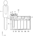
- FIG. 2 is a diagram illustrating an example of an installation mode of the banknote handling apparatus 10 in a financial institution or the like.
- the banknote handling apparatus 10 is installed below a counter 90 such as a business store.
- the banknote handling apparatus 10 is installed such that the central portion in the longitudinal direction (X direction in FIG. 2) is sandwiched between the counters 90.
- the deposit port 12 and the withdrawal port 14 so that the customer C inserts the deposited banknote into the deposit port 12 or the customer can pull out the withdrawn banknote from the first withdrawal port 14 or the second withdrawal port 15. , 15 are arranged on the customer C side.
- the banknote processing apparatus 10 performs, for example, deposit processing, withdrawal processing, and the like.
- the deposit process is a process of stacking the banknotes in the deposit port 12 in the banknote cassettes 30A to 30E.
- the withdrawal process is a process of accumulating the banknotes in the banknote cassettes 30A to 30E in the first withdrawal port 14 or the second withdrawal port 15.
- banknotes inserted into the deposit port 12 by a customer or the like are separated and fed out one by one.
- the fed banknotes are conveyed to the banknote recognition unit 20 by the conveyance unit 24.
- the banknote recognition part 20 performs banknote discrimination, and the banknote whose discrimination result was normal is conveyed to the temporary storage part 22 and accumulated.
- the banknote (reject banknote) in which the discrimination result by the banknote recognition unit 20 is abnormal is accumulated in the first withdrawal port 14 or the second withdrawal port 15.
- the banknotes accumulated in the temporary storage unit 22 are separated one by one and conveyed to the banknote recognition unit 20.
- banknotes for which the discrimination result by the banknote recognition unit 20 is normal are accumulated in the banknote cassettes 30A to 30E corresponding to the denominations.
- banknotes for which the discrimination result by the banknote recognition unit 20 is abnormal such as running abnormal banknotes such as a fouled banknote, a folded banknote, and a skew banknote, are accumulated in the dedicated storage cassette 35.
- banknotes are separated and fed from the banknote cassettes 30A to 30E one by one according to the amount designated by the customer.
- the fed banknotes are conveyed to the banknote recognition unit 20 by the conveyance unit 24.
- the banknote recognition unit 20 performs banknote discrimination, and banknotes for which the discrimination result is normal are accumulated in the first withdrawal port 14 or the second withdrawal port 15.
- the money is selectively accumulated (collected) at the first withdrawal port 14 or the second withdrawal port 15.
- banknotes with an abnormal discrimination result that is, banknotes that cannot be paid to the customer, are accumulated in the storage-only cassette 35.
- the banknote handling apparatus 10 is subjected to various maintenance (for example, elimination of banknote jam) and maintenance by the staff.
- the banknote processing apparatus 10 has the upper unit 53 and the lower unit 56 which can be pulled out or inserted with respect to the apparatus main body 50, as shown in FIG.
- the lower unit 56 is located below the upper unit 53.
- the upper unit 53 includes the deposit port 12, the first withdrawal port 14, the second withdrawal port 15, the banknote recognition unit 20, the temporary storage unit 22, and the transport unit 24.
- a staff member pulls out the upper unit 53 and removes the jammed banknote, or performs maintenance of the upper unit 53.
- the upper unit 53 is pulled out or inserted along a slide rail (not shown) of the upper housing 52 of the apparatus main body 50.
- FIG. 3 is a schematic diagram showing a pulling direction of the upper unit 53. As shown in FIG. 3, the upper unit 53 is pulled out from one end side in the longitudinal direction with respect to the apparatus main body 50 in the X2 direction (customer side) and is inserted into the apparatus main body 50 in the X1 direction.
- the lower unit 56 includes the banknote cassettes 30A to 30E and the storage cassette 35 described above. If the cassette is exchanged to collect or replenish banknotes in the banknote cassettes 30A-30E or the storage cassette 35, or if a banknote jam occurs in the banknote cassettes 30A-30E or the storage cassette 35, the staff The unit 56 is pulled out, the cassette in the lower unit 56 is exchanged, or the jammed banknote is removed.
- banknote cassettes 30A to 30E and a dedicated storage cassette 35 are detachably set.
- the lower unit 56 is pulled out or inserted along a slit rail (not shown) of the lower housing 55.
- the bill cassettes 30A to 30E and the storage-dedicated cassette 35 can be exchanged.
- FIG. 4A and FIG. 4B are schematic views showing the pulling direction of the lower unit 56 in the first embodiment.
- 4A is a view of the banknote handling apparatus 10 as viewed from above
- FIG. 4B is a view of the banknote handling apparatus 10 as viewed from the front.
- the lower unit 56 is pulled out from the other end side in the longitudinal direction with respect to the apparatus main body 50 in the X1 direction (direction away from the customer), and is inserted into the apparatus main body 50 in the X2 direction.
- the pulling direction of the upper unit 53 and the pulling direction of the lower unit 56 are opposite to each other.
- the upper unit 53 and the lower unit 56 are pulled out separately, but the present invention is not limited to this.
- the upper unit 53 and the lower unit 56 may be pulled out together.
- the apparatus main body 50 is stable and the upper unit 53 and the lower unit 56 can be pulled out together.
- FIG. 5 is a diagram for explaining an example in which the upper unit 53 and the lower unit 56 are both pulled out.
- An openable / closable door 59 (see FIG. 1) is provided on the other end side of the bill processing apparatus 10 in the longitudinal direction.
- the open / close door 59 is normally locked, and is unlocked when the lower unit 56 is pulled out. Then, as shown in FIG. 4A, the lower unit 56 is pulled out when the open / close door 59 is open.
- FIG. 4B the open / close door 59 is omitted for convenience of explanation.
- the staff unlocks the opening / closing door 59 and opens the opening / closing door 59, and then pulls out the lower unit 56 to the near side (position away from the customer).
- the staff moves the bill cassettes 30A to 30E and the storage-dedicated cassette 35 upward and takes them out of the lower unit 56.
- the bill cassettes 30A to 30E and the storage-dedicated cassette 35 are pulled out at a position away from the customer.
- the staff member sets a new cassette in the lower unit 56 and inserts it into the apparatus main body 50, thereby completing the exchange of the bill cassettes 30A to 30E and the storage cassette 35.
- FIG. 6 is a diagram illustrating an example of an installation mode of a banknote processing apparatus 900 according to a comparative example in a sales office or the like.
- the configuration of the upper part of the banknote processing apparatus 900 is the same as that of the banknote processing apparatus 10 shown in FIG. 1, but the configuration of the lower part of the banknote processing apparatus 900 is different from that of the banknote processing apparatus 10.
- the opening / closing door 959 is located on the customer C side, and the lower unit 956 is pulled out to the customer C side.
- FIG. 7 is a schematic diagram for explaining the drawer of the lower unit 956 in the banknote handling apparatus 900 according to the comparative example.
- the staff moves to the customer C side and unlocks the opening / closing door 959 in front of the customer and opens and closes it. After opening the door 959, the lower unit 956 is pulled out.
- the door 959 is omitted for convenience of explanation.
- the staff performs the work of exchanging cassettes and removing jammed banknotes in front of the customer C. For this reason, there is a risk that the banknote cassettes 30A to 30E and the storage cassette 35 may be exposed to customers and robbed, and the internal mechanism of the banknote processing apparatus 900, the housing structure, the viewpoint of the door, and the locking position may be looked into. is there. In addition, there is a risk of theft if the customer touches the jam bill from the blind spot of the staff.
- the lower unit 56 is pulled out to the side opposite to the customer C side, and the bill cassettes 30A to 30E and the storage cassette 35 are taken out at a position away from the customer C.
- the lower unit 56 since the lower unit 56 can be pulled away from the customer, the customer can be prevented from touching the jam bill.
- the counter 90 blocks the field of view of the customer who sees the lower unit 56, so that it becomes difficult for the customer to visually recognize the internal structure of the banknote cassettes 30A to 30E and the storage cassette 35. Can be improved.
- the banknote processing apparatus 10 has been described as an example of the cash processing apparatus, but is not limited thereto.
- the cash processing apparatus may be a coin processing apparatus capable of depositing / withdrawing and storing coins. Also in such a case, it becomes difficult for the customer to visually recognize the internal structure of the coin processing device by pulling out the lower unit including the storage unit for storing the coin in a direction away from the customer side, and the crime prevention performance can be improved.
- FIG. 8 is a diagram illustrating an example of an internal configuration of the banknote handling apparatus 100 according to the second embodiment.
- the door 59 is provided on the staff side as shown in FIG. 1, but in the second embodiment, the door 59 is provided on the customer side as shown in FIG. .
- the lower unit 56 is pulled out in the X1 direction from the other end in the longitudinal direction of the apparatus main body.
- the lower unit 56 is extended in the longitudinal direction of the apparatus main body. It is pulled out in the X2 direction from one end side.
- FIG. 9A and FIG. 9B are diagrams showing an example of an installation aspect of the banknote handling apparatus 100 in a financial institution or the like.
- the banknote handling apparatus 100 is attached to an installation stand 180 below the counter 190 (specifically, fixed).
- the installation table 180 has a slide mechanism 182 that can move in the X1 and X2 directions while holding the banknote processing apparatus 100 with respect to the counter base 192 below the counter 190.
- the installation table 180 moves to a position away from the customer by moving in the X1 direction.
- the counter 190 according to the second embodiment has an opening 193 for preventing interference when the banknote handling apparatus 100 moves in the X1 direction, as shown in FIG. 9B.
- FIG. 10 is a schematic diagram showing a state where the installation stand 180 holding the banknote handling apparatus 100 has moved in the X1 direction.
- FIG. 11 is a schematic diagram for explaining the flow of taking out the banknote cassettes 30A to 30E and the storage-dedicated cassette 35.
- the staff moves the installation stand 180 to which the banknote handling apparatus 100 is fixed in the X1 direction (a position away from the customer).
- the deposit port 12, the first withdrawal port 14, and the second withdrawal port 15 are located on the opposite side of the counter 190.
- the amount of movement of the installation table 180 in the X1 direction is an amount by which the main body drawn in the X2 direction does not pass through the opening 193 of the counter 190 (see FIG. 11).
- the staff member is located between the banknote processing apparatus 100 located at a position away from the customer and the counter 190, unlocks the open / close door 59 and opens the open / close door 59, as shown in FIG.
- the lower unit 56 is pulled out from one end side of the apparatus main body 50 in the X2 direction.
- the staff moves the bill cassettes 30A to 30E and the storage cassette 35 upward and takes them out.
- the bill cassettes 30A to 30E and the storage cassette 35 are taken out at a position away from the customer by moving the installation table 180 in the X1 direction. Also in this case, since the lower unit 56 of the banknote handling apparatus 100 can be separated from the customer, the customer can be prevented from touching the jammed banknote. Further, when the main body is pulled out, the counter 190 blocks the view of the customer who sees the lower unit 56, so that it becomes difficult for the customer to visually recognize the internal structure of the banknote cassettes 30A to 30E and the dedicated storage cassette 35. It can be improved.
- the customer inserts a deposited banknote into the depositing port 12 and withdraws the withdrawal banknote from the first withdrawal port 14 or the second withdrawal port 15.
- the banknote processing apparatus is installed at a financial institution's sales office so that a staff member who is an inserter inserts a deposited banknote into a depositing port and pulls out a withdrawal banknote from the dispensing port. is set up.
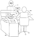
- FIG. 12 is a diagram illustrating an example of an installation mode of the banknote handling apparatus 200 according to the third embodiment in a financial institution or the like.
- the banknote handling apparatus 200 is provided below the counter 290 between the customer C and the staff U who face each other.
- a customer faces the one end side of the longitudinal direction in which the deposit port 212 of the banknote processing apparatus 200, the 1st withdrawal port 214, and the 2nd withdrawal port 215 were provided, and the staff U is the staff U. It faces the other end side in the longitudinal direction of the banknote handling apparatus 200.
- the customer who came to the sales office gives the banknote to the staff U sitting on the other side of the counter 290.
- the staff U inserts the received banknote into the deposit port 212 of the banknote processing apparatus 200.
- the inserted banknote is taken into the banknote processing apparatus 200, the number of sheets is counted, the type of banknote is determined, and stored in a cassette or the like.
- the position of the deposit port 212 is set so that the customer C can easily confirm the act of the staff inserting the bill into the deposit port.
- the deposit port 212 is provided at a position on the upper side of the banknote handling apparatus 200 so as to be within the field of view of the customer who has handed over the banknote.
- FIG. 13 is a diagram for explaining the relationship between the flow of bill insertion into the deposit port 212 and the customer's line of sight in the third embodiment.
- the depositing port 212 of the banknote processing apparatus 200 faces upward at an angle that is not hidden by the shadow of the banknote processing apparatus 200 when viewed from the customer C standing behind the banknote processing apparatus 200. It is an opening arranged on the upper surface side.
- the 1st withdrawal port 214 and the 2nd withdrawal port 215 are arrange
- FIG. 14 is a diagram for explaining a comparative example.
- the deposit port 952 is disposed on the front side facing the staff.
- the banknote is hidden behind the banknote processing device 950, and is located in the blind spot of the customer's line of sight.
- the customer cannot confirm even if the staff pulls out the banknote to be inserted into the deposit port 952.
- the arm of the staff passes only the upper side of the bill processing apparatus 200 when the bill received from the customer is inserted into the deposit port 212. .
- the customer can continue confirming a motion until an employee inserts a banknote into the deposit port 212.
- troubles can be prevented from occurring with customers.
- FIG. 15 is a diagram for explaining a modification of the banknote handling apparatus 200 according to the third embodiment.
- the deposit port 213 is arranged on the upper side surface of the banknote handling apparatus 200 so as to face the rear side (customer side).
- the position of the deposit port 213 is a position in the field of view of the customer standing behind the banknote processing apparatus 200.
Abstract
Description
(1-1.現金処理装置の内部構成例)
図1を参照しながら、第1の実施形態に係る現金処理装置の一例である紙幣処理装置10の内部構成例について説明する。 <1. First Embodiment>
(1-1. Internal configuration example of cash processing device)
With reference to FIG. 1, an internal configuration example of a
紙幣処理装置10は、職員により種々のメンテナンス(例えば、紙幣のジャムの解消)や保守等が行われる。そして、紙幣処理装置10は、図1に示すように、装置本体50に対して引き出し又は挿入可能な上部ユニット53と下部ユニット56を有する。下部ユニット56は、上部ユニット53の下方に位置する。 (1-2. Pulling out the upper unit and lower unit)
The
第1の実施形態に係る紙幣処理装置10の有効性について、図6及び図7に示す比較例と対比して、説明する。 (1-3. Effectiveness of the first embodiment)
The effectiveness of the
図8は、第2の実施形態に係る紙幣処理装置100の内部構成の一例を示す図である。第1の実施形態では、図1に示すように開閉扉59が職員側に設けられていたが、第2の実施形態では、図8に示すように開閉扉59が顧客側に設けられている。また、第1の実施形態では、下部ユニット56が装置本体の長手方向の他端側からX1方向に引き出されることとしたが、第2の実施形態では、下部ユニット56が装置本体の長手方向の一端側からX2方向に引き出される。 <2. Second Embodiment>
FIG. 8 is a diagram illustrating an example of an internal configuration of the
第1の実施形態及び第2の実施形態では、顧客が、入金口12に入金紙幣を投入し、第1出金口14又は第2出金口15から出金紙幣を抜き取っている。これに対して、第3の実施形態では、投入者である職員が、入金口に入金紙幣の投入し、出金口から出金紙幣を抜き取るように、紙幣処理装置が金融機関の営業店に設置されている。 <3. Third Embodiment>
In the first embodiment and the second embodiment, the customer inserts a deposited banknote into the depositing
12 入金口
14 第1出金口
15 第2出金口
30A~30E 紙幣カセット
35 収納専用カセット
50 装置本体
53 上部ユニット
55 下部筐体
56 下部ユニット
59 開閉扉
180 設置台
212、213 入金口
C 顧客
DESCRIPTION OF
Claims (10)
- 顧客に対向する装置本体の長手方向の一端側に設けられ、現金が投入され又は現金を排出する入出金部と、
前記装置本体に対して着脱可能に設けられ、現金を収納する収納部と、
を備え、
前記収納部は、前記顧客から遠ざかる位置で前記装置本体から取り出される、現金処理装置。 A deposit / withdrawal unit that is provided on one end side in the longitudinal direction of the apparatus main body facing the customer and in which cash is inserted or discharged;
A storage unit that is detachably attached to the apparatus body, and stores cash;
With
The said storage part is a cash processing apparatus taken out from the said apparatus main body in the position away from the said customer. - 請求項1に記載の現金処理装置において、
前記収納部は、前記装置本体に対して前記長手方向の他端側から引き出し可能に設けられ、
前記収納部は、前記他端側から引き出された後に取り出される、現金処理装置。 The cash processing apparatus according to claim 1,
The storage portion is provided so as to be drawable from the other end side in the longitudinal direction with respect to the apparatus main body,
The said storage part is a cash processing apparatus taken out after being pulled out from the said other end side. - 請求項2に記載の現金処理装置において、
前記入出金部は、前記装置本体に対して前記長手方向の一端側から引き出し可能に設けられている、現金処理装置。 The cash processing apparatus according to claim 2,
The cash deposit / withdrawal unit is provided so as to be able to be pulled out from one end side in the longitudinal direction with respect to the apparatus main body. - 請求項3に記載の現金処理装置において、
前記収納部は、前記入出金部の下方に位置し、
前記収納部と前記入出金部は、共に引き出される、現金処理装置。 In the cash processing apparatus according to claim 3,
The storage unit is located below the deposit / withdrawal unit,
The storage unit and the deposit / withdrawal unit are both withdrawn. - 請求項1に記載の現金処理装置において、
前記長手方向の他端側に開閉可能な開閉扉を更に備え、
前記開閉扉の開状態において、前記収納部が前記他端側から引き出される、現金処理装置。 The cash processing apparatus according to claim 1,
Further comprising an openable / closable door on the other end side in the longitudinal direction,
A cash processing apparatus in which the storage portion is pulled out from the other end side in the open state of the door. - 請求項1に記載の現金処理装置において、
前記現金処理装置は、前記顧客から遠ざかる位置へ向けて移動可能な設置台に取り付けられ、
前記収納部は、前記装置本体に対して前記長手方向の一端側から引き出し可能に設けられ、
前記設置台が前記位置へ移動した場合に、前記収納部は、前記一端側から引き出された後に取り出される、現金処理装置。 The cash processing apparatus according to claim 1,
The cash processing apparatus is attached to an installation table that is movable toward a position away from the customer;
The storage portion is provided so as to be drawable from one end side in the longitudinal direction with respect to the apparatus main body,
When the installation base moves to the position, the storage unit is taken out after being pulled out from the one end side. - 請求項6に記載の現金処理装置において、
前記現金処理装置は、前記長手方向の中央部が対面用カウンタに挟まれるように設置され、
前記収納部は、前記対面用カウンタから見て一方側に位置する前記入出金部が、前記設置台の移動に伴い前記対面用カウンタから見て他方側へ移動した後に、前記一端側から引き出される、現金処理装置。 The cash processing apparatus according to claim 6,
The cash processing apparatus is installed such that the central part in the longitudinal direction is sandwiched between counters for facing,
The storage unit is pulled out from the one end side after the deposit / withdrawal unit located on one side as viewed from the facing counter moves to the other side as viewed from the facing counter as the installation table moves. Cash processing device. - 装置本体の長手方向の一端側に対向する顧客から受け取った現金を、前記装置本体の長手方向の他端側に対向する投入者が投入する現金処理装置であって、
前記投入者により前記現金が投入される入金口を備え、
前記入金口は、前記現金を渡した前記顧客の視界内に入るように、装置本体の上部側の位置に設けられている、現金処理装置。 A cash processing apparatus in which cash received from a customer facing one end in the longitudinal direction of the apparatus body is thrown by a thrower facing the other end in the longitudinal direction of the apparatus body,
A deposit port through which the cash is inserted by the input person;
The cash processing apparatus is provided at a position on the upper side of the apparatus main body so that the deposit port is within the field of view of the customer who has delivered the cash. - 請求項8に記載の現金処理装置において、
前記入金口は、前記装置本体の上面側において上方を向いた開口である、現金処理装置。 The cash processing apparatus according to claim 8,
The depositing port is a cash processing apparatus that is an opening facing upward on the upper surface side of the apparatus main body. - 請求項8に記載の現金処理装置において、
前記入金口は、前記装置本体の上部側面において前記一端側を向いた開口である、現金処理装置。
The cash processing apparatus according to claim 8,
The depositing port is a cash processing apparatus that is an opening facing the one end side on the upper side surface of the apparatus main body.
Priority Applications (3)
| Application Number | Priority Date | Filing Date | Title |
|---|---|---|---|
| CN201380064167.8A CN104838429B (en) | 2012-12-20 | 2013-10-17 | Cash treatment |
| BR112015014018A BR112015014018A2 (en) | 2012-12-20 | 2013-10-17 | cash processing device |
| US14/649,913 US9666011B2 (en) | 2012-12-20 | 2013-10-17 | Cash processing apparatus |
Applications Claiming Priority (2)
| Application Number | Priority Date | Filing Date | Title |
|---|---|---|---|
| JP2012278389A JP6490330B2 (en) | 2012-12-20 | 2012-12-20 | Cash processing equipment |
| JP2012-278389 | 2012-12-20 |
Publications (1)
| Publication Number | Publication Date |
|---|---|
| WO2014097727A1 true WO2014097727A1 (en) | 2014-06-26 |
Family
ID=50978076
Family Applications (1)
| Application Number | Title | Priority Date | Filing Date |
|---|---|---|---|
| PCT/JP2013/078124 WO2014097727A1 (en) | 2012-12-20 | 2013-10-17 | Money processing device |
Country Status (5)
| Country | Link |
|---|---|
| US (1) | US9666011B2 (en) |
| JP (1) | JP6490330B2 (en) |
| CN (1) | CN104838429B (en) |
| BR (1) | BR112015014018A2 (en) |
| WO (1) | WO2014097727A1 (en) |
Cited By (1)
| Publication number | Priority date | Publication date | Assignee | Title |
|---|---|---|---|---|
| CN107077765A (en) * | 2014-11-18 | 2017-08-18 | 光荣株式会社 | Bank note treatment device |
Families Citing this family (1)
| Publication number | Priority date | Publication date | Assignee | Title |
|---|---|---|---|---|
| WO2018191915A1 (en) * | 2017-04-20 | 2018-10-25 | 深圳怡化电脑股份有限公司 | Cash deposit and withdrawal machine and core maintenance device thereof |
Citations (3)
| Publication number | Priority date | Publication date | Assignee | Title |
|---|---|---|---|---|
| JPS62157994A (en) * | 1985-12-28 | 1987-07-13 | 沖電気工業株式会社 | Recycling type paper money teller |
| JPH01121993A (en) * | 1987-11-06 | 1989-05-15 | Oki Electric Ind Co Ltd | Automatic transactor for window |
| JPH07168962A (en) * | 1993-09-23 | 1995-07-04 | Ascom Autelca Ag | Revenue and expenditure safe provided with safe-operating device capable of being operated selectively by two cashiers |
Family Cites Families (8)
| Publication number | Priority date | Publication date | Assignee | Title |
|---|---|---|---|---|
| JPH05332067A (en) * | 1991-05-01 | 1993-12-14 | Hitachi Ltd | Booth for autoamtic transcation device |
| JP3600762B2 (en) | 1999-09-22 | 2004-12-15 | グローリー工業株式会社 | Circulation type money handling equipment |
| JP3978034B2 (en) * | 2000-12-25 | 2007-09-19 | 日立オムロンターミナルソリューションズ株式会社 | Banknote deposit and withdrawal machine |
| US6719120B2 (en) * | 2000-12-25 | 2004-04-13 | Hitachi, Ltd. | Bill receiving/dispensing machine |
| US7500568B2 (en) * | 2005-06-16 | 2009-03-10 | Traidis | Standalone device and method for managing, depositing and dispensing cash |
| CN101075367A (en) * | 2007-06-25 | 2007-11-21 | 广州广电运通金融电子股份有限公司 | Currency circulator |
| JP2009289100A (en) * | 2008-05-30 | 2009-12-10 | Oki Electric Ind Co Ltd | Cassette attaching and detaching structure for automated teller machine |
| JP4872993B2 (en) | 2008-09-17 | 2012-02-08 | 沖電気工業株式会社 | Cash machine for window and forced deposit method |
-
2012
- 2012-12-20 JP JP2012278389A patent/JP6490330B2/en active Active
-
2013
- 2013-10-17 US US14/649,913 patent/US9666011B2/en active Active
- 2013-10-17 BR BR112015014018A patent/BR112015014018A2/en not_active Application Discontinuation
- 2013-10-17 CN CN201380064167.8A patent/CN104838429B/en not_active Expired - Fee Related
- 2013-10-17 WO PCT/JP2013/078124 patent/WO2014097727A1/en active Application Filing
Patent Citations (3)
| Publication number | Priority date | Publication date | Assignee | Title |
|---|---|---|---|---|
| JPS62157994A (en) * | 1985-12-28 | 1987-07-13 | 沖電気工業株式会社 | Recycling type paper money teller |
| JPH01121993A (en) * | 1987-11-06 | 1989-05-15 | Oki Electric Ind Co Ltd | Automatic transactor for window |
| JPH07168962A (en) * | 1993-09-23 | 1995-07-04 | Ascom Autelca Ag | Revenue and expenditure safe provided with safe-operating device capable of being operated selectively by two cashiers |
Cited By (3)
| Publication number | Priority date | Publication date | Assignee | Title |
|---|---|---|---|---|
| CN107077765A (en) * | 2014-11-18 | 2017-08-18 | 光荣株式会社 | Bank note treatment device |
| EP3223250A4 (en) * | 2014-11-18 | 2017-12-06 | Glory Ltd. | Banknote processing device |
| CN107077765B (en) * | 2014-11-18 | 2019-09-27 | 光荣株式会社 | Bank note treatment device |
Also Published As
| Publication number | Publication date |
|---|---|
| US20160240031A1 (en) | 2016-08-18 |
| CN104838429B (en) | 2017-10-24 |
| US9666011B2 (en) | 2017-05-30 |
| CN104838429A (en) | 2015-08-12 |
| JP6490330B2 (en) | 2019-03-27 |
| BR112015014018A2 (en) | 2017-07-11 |
| JP2014123217A (en) | 2014-07-03 |
Similar Documents
| Publication | Publication Date | Title |
|---|---|---|
| JP5821585B2 (en) | Banknote handling equipment | |
| JP4654268B2 (en) | Banknote deposit and withdrawal device | |
| KR101665613B1 (en) | Teller cash recycler and control method thereof | |
| JP6382176B2 (en) | Financial equipment | |
| JP5821588B2 (en) | Banknote handling equipment | |
| WO2012002036A1 (en) | Automatic transaction apparatus | |
| JP5954037B2 (en) | Bill processing apparatus and bill processing method | |
| JP4694216B2 (en) | Automatic cash transaction equipment | |
| JP6490330B2 (en) | Cash processing equipment | |
| JP2018205790A (en) | Cash processing system, cash processor and cash processing method | |
| JP5487278B2 (en) | Banknote deposit and withdrawal device | |
| KR101750394B1 (en) | Teller cash recycler control method | |
| JP3511236B2 (en) | Paper sheet handling equipment | |
| KR101618438B1 (en) | Medium storage box and financial device | |
| KR101751598B1 (en) | Financial device | |
| JP6089977B2 (en) | Cash processing equipment | |
| KR101672597B1 (en) | Medium processing apparatus and financial device | |
| JP5498516B2 (en) | Banknote deposit and withdrawal machine | |
| JP5904048B2 (en) | Bill processing apparatus and bill processing method | |
| JP5498549B2 (en) | Banknote deposit and withdrawal machine | |
| JP5147925B2 (en) | Banknote deposit and withdrawal device | |
| JP2012238340A (en) | Automated teller machine | |
| JP2512722B2 (en) | Automatic deposit / withdrawal device | |
| JP2010282664A (en) | Automatic teller machine | |
| JPS62186396A (en) | Paper money recovery for automatic paper money teller equipment |
Legal Events
| Date | Code | Title | Description |
|---|---|---|---|
| 121 | Ep: the epo has been informed by wipo that ep was designated in this application |
Ref document number: 13865868 Country of ref document: EP Kind code of ref document: A1 |
|
| WWE | Wipo information: entry into national phase |
Ref document number: 14649913 Country of ref document: US |
|
| NENP | Non-entry into the national phase |
Ref country code: DE |
|
| REG | Reference to national code |
Ref country code: BR Ref legal event code: B01A Ref document number: 112015014018 Country of ref document: BR |
|
| 122 | Ep: pct application non-entry in european phase |
Ref document number: 13865868 Country of ref document: EP Kind code of ref document: A1 |
|
| ENP | Entry into the national phase |
Ref document number: 112015014018 Country of ref document: BR Kind code of ref document: A2 Effective date: 20150615 |