WO2014097538A1 - Sliding seal and seal structure - Google Patents
Sliding seal and seal structure Download PDFInfo
- Publication number
- WO2014097538A1 WO2014097538A1 PCT/JP2013/006784 JP2013006784W WO2014097538A1 WO 2014097538 A1 WO2014097538 A1 WO 2014097538A1 JP 2013006784 W JP2013006784 W JP 2013006784W WO 2014097538 A1 WO2014097538 A1 WO 2014097538A1
- Authority
- WO
- WIPO (PCT)
- Prior art keywords
- seal
- lubricant
- sliding
- pressure fluid
- holding piece
- Prior art date
Links
Images


Classifications
-
- F—MECHANICAL ENGINEERING; LIGHTING; HEATING; WEAPONS; BLASTING
- F16—ENGINEERING ELEMENTS AND UNITS; GENERAL MEASURES FOR PRODUCING AND MAINTAINING EFFECTIVE FUNCTIONING OF MACHINES OR INSTALLATIONS; THERMAL INSULATION IN GENERAL
- F16J—PISTONS; CYLINDERS; SEALINGS
- F16J15/00—Sealings
- F16J15/16—Sealings between relatively-moving surfaces
- F16J15/18—Sealings between relatively-moving surfaces with stuffing-boxes for elastic or plastic packings
- F16J15/182—Sealings between relatively-moving surfaces with stuffing-boxes for elastic or plastic packings with lubricating, cooling or draining means
-
- F—MECHANICAL ENGINEERING; LIGHTING; HEATING; WEAPONS; BLASTING
- F16—ENGINEERING ELEMENTS AND UNITS; GENERAL MEASURES FOR PRODUCING AND MAINTAINING EFFECTIVE FUNCTIONING OF MACHINES OR INSTALLATIONS; THERMAL INSULATION IN GENERAL
- F16J—PISTONS; CYLINDERS; SEALINGS
- F16J15/00—Sealings
- F16J15/16—Sealings between relatively-moving surfaces
- F16J15/32—Sealings between relatively-moving surfaces with elastic sealings, e.g. O-rings
- F16J15/324—Arrangements for lubrication or cooling of the sealing itself
-
- F—MECHANICAL ENGINEERING; LIGHTING; HEATING; WEAPONS; BLASTING
- F16—ENGINEERING ELEMENTS AND UNITS; GENERAL MEASURES FOR PRODUCING AND MAINTAINING EFFECTIVE FUNCTIONING OF MACHINES OR INSTALLATIONS; THERMAL INSULATION IN GENERAL
- F16F—SPRINGS; SHOCK-ABSORBERS; MEANS FOR DAMPING VIBRATION
- F16F9/00—Springs, vibration-dampers, shock-absorbers, or similarly-constructed movement-dampers using a fluid or the equivalent as damping medium
- F16F9/32—Details
-
- F—MECHANICAL ENGINEERING; LIGHTING; HEATING; WEAPONS; BLASTING
- F16—ENGINEERING ELEMENTS AND UNITS; GENERAL MEASURES FOR PRODUCING AND MAINTAINING EFFECTIVE FUNCTIONING OF MACHINES OR INSTALLATIONS; THERMAL INSULATION IN GENERAL
- F16J—PISTONS; CYLINDERS; SEALINGS
- F16J15/00—Sealings
- F16J15/002—Sealings comprising at least two sealings in succession
- F16J15/004—Sealings comprising at least two sealings in succession forming of recuperation chamber for the leaking fluid
-
- F—MECHANICAL ENGINEERING; LIGHTING; HEATING; WEAPONS; BLASTING
- F16—ENGINEERING ELEMENTS AND UNITS; GENERAL MEASURES FOR PRODUCING AND MAINTAINING EFFECTIVE FUNCTIONING OF MACHINES OR INSTALLATIONS; THERMAL INSULATION IN GENERAL
- F16J—PISTONS; CYLINDERS; SEALINGS
- F16J15/00—Sealings
- F16J15/002—Sealings comprising at least two sealings in succession
- F16J15/006—Sealings comprising at least two sealings in succession with division of the pressure
-
- F—MECHANICAL ENGINEERING; LIGHTING; HEATING; WEAPONS; BLASTING
- F16—ENGINEERING ELEMENTS AND UNITS; GENERAL MEASURES FOR PRODUCING AND MAINTAINING EFFECTIVE FUNCTIONING OF MACHINES OR INSTALLATIONS; THERMAL INSULATION IN GENERAL
- F16J—PISTONS; CYLINDERS; SEALINGS
- F16J15/00—Sealings
- F16J15/002—Sealings comprising at least two sealings in succession
- F16J15/008—Sealings comprising at least two sealings in succession with provision to put out of action at least one sealing; One sealing sealing only on standstill; Emergency or servicing sealings
-
- F—MECHANICAL ENGINEERING; LIGHTING; HEATING; WEAPONS; BLASTING
- F16—ENGINEERING ELEMENTS AND UNITS; GENERAL MEASURES FOR PRODUCING AND MAINTAINING EFFECTIVE FUNCTIONING OF MACHINES OR INSTALLATIONS; THERMAL INSULATION IN GENERAL
- F16J—PISTONS; CYLINDERS; SEALINGS
- F16J15/00—Sealings
- F16J15/16—Sealings between relatively-moving surfaces
- F16J15/32—Sealings between relatively-moving surfaces with elastic sealings, e.g. O-rings
- F16J15/3204—Sealings between relatively-moving surfaces with elastic sealings, e.g. O-rings with at least one lip
- F16J15/3232—Sealings between relatively-moving surfaces with elastic sealings, e.g. O-rings with at least one lip having two or more lips
-
- F—MECHANICAL ENGINEERING; LIGHTING; HEATING; WEAPONS; BLASTING
- F16—ENGINEERING ELEMENTS AND UNITS; GENERAL MEASURES FOR PRODUCING AND MAINTAINING EFFECTIVE FUNCTIONING OF MACHINES OR INSTALLATIONS; THERMAL INSULATION IN GENERAL
- F16J—PISTONS; CYLINDERS; SEALINGS
- F16J15/00—Sealings
- F16J15/56—Other sealings for reciprocating rods
-
- F—MECHANICAL ENGINEERING; LIGHTING; HEATING; WEAPONS; BLASTING
- F16—ENGINEERING ELEMENTS AND UNITS; GENERAL MEASURES FOR PRODUCING AND MAINTAINING EFFECTIVE FUNCTIONING OF MACHINES OR INSTALLATIONS; THERMAL INSULATION IN GENERAL
- F16F—SPRINGS; SHOCK-ABSORBERS; MEANS FOR DAMPING VIBRATION
- F16F9/00—Springs, vibration-dampers, shock-absorbers, or similarly-constructed movement-dampers using a fluid or the equivalent as damping medium
- F16F9/32—Details
- F16F9/36—Special sealings, including sealings or guides for piston-rods
- F16F9/365—Special sealings, including sealings or guides for piston-rods the sealing arrangement having a pressurised chamber separated from the damping medium
Definitions
- the present invention is for sealing an annular gap between two members in which the first member is movable with respect to the second member, and is applied to, for example, a sliding portion that operates with a small stroke in which fluid pressure acts.
- the present invention relates to a sliding seal and a seal structure.
- An example of a conventional sliding seal is a ring packing (see, for example, Patent Document 1).
- This ring packing is for appropriately managing the sliding resistance between the shaft body that slidably supports the shaft body that is displaced in conjunction with the diaphragm and the shaft body. It is attached to.
- the ring packing has an oval cross section, and a groove is formed along the circumferential direction on the outer peripheral surface of the ring packing facing the inner surface of the cylindrical body.
- this ring packing does not have a function for preventing the grease adhering to the concave groove from flowing out of the concave groove, the grease applied to the concave groove is caused to vibrate by sliding the shaft body.
- the present invention has been made to solve the above-described problems, and an object thereof is to provide a long-life sliding seal and seal structure.
- the sliding seal according to the present invention is for sealing the annular gap between two members movable with respect to the second member by the first member to partition the high pressure side and the low pressure side.
- a sliding seal disposed in an annular mounting groove provided in the member or the first member, a pressure fluid seal that is in sliding contact with the sliding surface of the first or second member, and a pressure higher than that of the pressure fluid seal And a lubricant holding piece which forms a lubricant accommodating space between the pressure fluid seal and the pressure fluid seal.
- the annular gap between the first and second members can be sealed by the pressure fluid seal.
- the lubricant can be held in the lubricant housing space, and the lubricant slides between the pressure fluid seal and the sliding surface when the first member moves relative to the second member.
- the part can be lubricated. Therefore, the starting frictional resistance and the sliding frictional resistance between the pressure fluid seal and the sliding surface can be reduced, and wear of the pressure fluid seal can be reduced.
- the lubricant held in the lubricant accommodating space formed on the high pressure side of the pressure fluid seal is moved between the pressure fluid seal and the sliding surface by the pressure fluid sealed on the high pressure side. Supplied. Thereby, this sliding part can be lubricated satisfactorily.
- the lubricant holding piece has a lubricant reservoir.
- the amount of lubricant retained in the lubricant accommodating space can be increased by the amount of lubricant retained in the lubricant reservoir. Therefore, the starting frictional resistance and sliding frictional resistance of the pressure fluid seal can be further reduced over a long period of time by the increased amount of the lubricant, and the wear resistance of the pressure fluid seal is improved. Can extend its life.
- the sliding seal according to the present invention may be provided with a lubricant seal provided on a higher pressure side than the lubricant accommodating space and in sliding contact with the sliding surface.
- the lubricant retained in the lubricant accommodating space can be prevented from flowing out to the high pressure side by the lubricant seal.
- the amount of crushing of the lip of the pressure fluid seal that is in sliding contact with the sliding surface is preferably larger than the amount of crushing of the lip of the lubricant seal that is in sliding contact with the sliding surface.
- the lubricant seal may be provided on the lubricant holding piece, and the lubricant holding piece may be disposed on the high pressure side of the mounting groove.
- the high-pressure side of the mounting groove can be sealed with the lubricant holding piece and the lubricant seal. Further, by providing the lubricant seal on the lubricant holding piece, the number of parts of the slide seal is reduced, and the labor for assembling the slide seal with respect to the second or first member can be reduced.
- the lubricant seal may be formed separately from the lubricant holding piece.
- the lubricant seal that slides on the sliding surface and generates sliding friction is formed of a material with low frictional resistance and high wear resistance, and the lubricant holding piece that does not contact the sliding surface is: It can be formed of a material different from the lubricant seal. Therefore, the range of selection of each material of the lubricant seal and the lubricant holding piece can be expanded.
- the lubricant seal may be formed integrally with the lubricant holding piece.
- a backup ring may be provided adjacent to the side surface on the low pressure side of the pressure fluid seal.
- the tip of the pressure fluid seal on the sliding surface side is a gap between the sliding surface and the second member or the first member. It is possible to prevent entry and biting. Therefore, it is possible to prevent a decrease in the sealing degree on the high-pressure side due to this.
- the seal structure according to the present invention is a seal structure provided with the sliding seal according to the present invention, and is formed in the second or first member provided with the mounting groove, and contains the lubricant from the outside.
- a supply path for supplying to the space is further provided.
- the slide seal according to the present invention is provided, and this slide seal operates in the same manner as described above.
- the lubricant can be supplied from the outside to the lubricant accommodating space through the supply path.
- a state where an appropriate amount of lubricant is supplied to the sliding portion between the pressure fluid seal and the sliding surface can be maintained for a long period of time.
- the lubricant reservoir is a groove that opens toward the sliding surface, and the groove and the supply path are connected via a communication hole formed in the lubricant holding piece. It is recommended that they communicate with each other.
- the lubricant held in the groove flows out of the opening of the groove and is supplied to the sliding surface. It is possible to facilitate the lubrication between the pressure fluid seal and the sliding surface. Since the lubricant is supplied to the lubricant reservoir through the supply path and the communication hole, the lubrication between the pressure fluid seal and the sliding surface can be reliably performed without interruption.
- the lubricant accommodating space is formed between the pressure fluid seal and the lubricant holding piece provided separately from the pressure fluid seal, so that it is large for holding the lubricant. Space can be secured.
- the amount of the lubricant flowing out from the lubricant accommodating space to the high pressure side can be reduced by the lubricant seal, and the lubricant can be held in the lubricant accommodating space for a long time. Therefore, the starting frictional resistance and sliding frictional resistance of the pressure fluid seal can be kept small over a long period of time, and the wear resistance of the pressure fluid seal can be improved and its life can be extended.
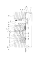
- FIG. 1 is a cross-sectional view showing a state in which the sliding seal according to the first embodiment of the present invention is mounted in the mounting groove of the second member.
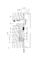
- FIG. 2 is a partially omitted sectional view showing a state in which the sliding seal according to the second embodiment of the present invention is mounted in the mounting groove of the second member.
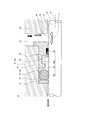
- FIG. 3 is a partially omitted sectional view showing a seal structure according to a third embodiment of the invention.
- FIG. 4 is a partially omitted cross-sectional view showing a state in which the sliding seal according to the fourth embodiment of the invention is mounted in the mounting groove of the second member.
- FIG. 5 is a partially omitted cross-sectional view showing a state in which the sliding seal according to the fifth embodiment of the invention is mounted in the mounting groove of the second member.
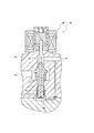
- FIG. 6 is a cross-sectional view showing a configuration of an electromagnetic pressure regulating valve to which the sliding seal according to the first embodiment is applied.
- This sliding seal 11 can be used for an electromagnetic pressure regulating valve 40 as shown in FIG. 6, for example.
- This electromagnetic pressure regulating valve 40 can control, for example, the flow rate (or pressure) of hydrogen to the fuel cell stack with high accuracy even when the upstream pressure is high, and can prevent leakage of hydrogen gas into the atmosphere. It is intended to prevent it.
- the electromagnetic pressure regulating valve 40 shown in FIG. 6 has a housing (second housing) having a valve passage 42 that connects a primary port (high-pressure side flow path 13c) connected to a hydrogen tank and a secondary port 41 connected to a fuel cell stack. Member) 43 and a valve body (first member) which is provided in the housing 43 and moves between a closed position for closing the valve passage 42 and an open position for opening the valve passage 42 to control the opening degree of the valve passage 42 12 and a high pressure seal member (sliding seal) 11 and a low pressure seal member 44 disposed on the outer periphery of the valve body 12, one end side of the valve body 12 is located on the valve passage 42 side, The other end side is located in a pressure feedback chamber 45 formed in the housing 43, and the sliding seal 11 and the low pressure seal member 44 are moved from one end side of the valve body 12 toward the other end side of the valve body 12.
- sliding seal 11 and low pressure In which further comprises a first space 46 and the secondary port 41 and the pressure equalizing path 47 connecting
- the electromagnetic proportional solenoid 48 is for moving the valve body (first member 12) in the opening / closing direction.
- the seal structure 40 in which the sliding seal 11 shown in FIG. 6 is used is, as shown in FIG. 1, between the two members in which the first member 12 is reciprocally movable with respect to the second member 43.
- the annular gap 14 can be sealed with the sliding seal 11.
- the fluid to be sealed (pressure fluid) is, for example, a gas, and the pressure is atmospheric pressure to 87.5 MPa.
- the apparatus 15 provided with the 1st and 2nd members 12 and 13 shown in this FIG. 1 is a pressure regulating valve, for example.
- the first member 12 on the sliding side is a valve body, and the portion shown in FIG. 1 is a columnar valve main body portion and forms a part of the valve body.
- the second member 13 on the fixed side is a valve hole (not shown) that is opened and closed by a valve body, a high-pressure channel 13c that is formed in communication therewith, and a cylindrical shape that is formed in communication therewith.
- the housing is provided with a mounting hole 16.
- a valve body (first member 12) is slidably mounted in the mounting hole 16 in the moving direction 17 shown in FIG. 1, and an annular mounting groove 18 is formed on the inner peripheral surface forming the mounting hole 16. Is formed.
- the annular mounting groove 18 has a rectangular cross section, and the sliding seal 11 is mounted in the rectangular mounting groove 18.
- the second member 13 which is a housing includes a first housing part 13a and a second housing part 13b, and the sliding seal 11 is mounted by dividing the first and second housing parts 13a and 13b. It can be attached to and detached from the groove 18.
- the sliding seal 11 is used to ensure the sealing performance of the sliding portion that operates with a relatively short stroke. Instead, the sealing performance of the sliding portion that operates with a relatively long stroke is ensured.
- Can be used for The sliding seal 11 can also be used for a sliding portion of equipment used at a pressure other than the atmospheric pressure to 87.5 MPa.
- the sliding seal 11 is used as a pressure regulating valve, but it can also be used to ensure the sealing performance of other devices including, for example, a piston seal or a rod seal.
- the sliding seal 11 includes a pressure fluid seal (high pressure seal) 19, a lubricant holding piece 20, a backup ring 21, and a lubricant seal 22, each of which has an annular shape. Is formed.
- a backup ring 21 is provided adjacent to the low pressure side surface of the pressure fluid seal 19, and the low pressure side surface of the backup ring 21 is in contact with the annular side wall surface of the mounting groove 18.
- the lubricant holding piece 20 is provided on the higher pressure side than the pressure fluid seal 19, and a lubricant accommodating space 26 is formed between the lubricant holding piece 20 and the pressure fluid seal 19. .
- the lubricant seal 22 is provided on the higher pressure side than the lubricant accommodating space 26 and is fixed to the inner peripheral surface of the lubricant holding piece 20.
- the pressure fluid seal 19 is made of, for example, a thermoplastic elastomer, specifically made of polyurethane.
- the thermoplastic elastomer has an intermediate elasticity between the crosslinked rubber material and the resin material, and preferably has a hardness of about JISA (durometer A) 90 to 96.
- an urethane (PU) elastomer is used.
- the material is not limited to this, and various materials such as styrene (SBC), olefin (TPO), vinyl chloride (TPVC), ester (TPEE), amide (TPAE) are applicable. It is. Moreover, it is good also as a product made from a rubber elastic body.
- the pressure fluid seal 19 has an outer peripheral surface formed in a substantially short cylindrical shape, and an inner peripheral portion 19a of the pressure fluid seal 19 including the center line 23 of the pressure fluid seal 19 is formed in a substantially semicircular shape.
- the inner peripheral portion 19 a is slidably in sliding contact with a sliding surface 24 that is an outer peripheral surface of the first member 12.
- the lubricant holding piece 20 can be formed of various materials, and may be made of, for example, a synthetic resin, and it is made of engineering plastic (PA, PC of general-purpose engineering plastic, PES of super engineering plastic, PEEK, etc.) It is good. Moreover, it is good also as metal.
- the lubricant holding piece 20 is mounted in a state where the outer peripheral surface of the substantially short cylindrical diameter is in close contact with the bottom surface 18a of the mounting groove 18, and the flange portion provided on the high pressure side is It is in close contact with the inner surface of the high-pressure channel 13c.
- the fixing method with respect to the 2nd member 13 of this lubricant holding piece 20 may be fastened to the 2nd member 13 with a screw, for example, and may be pressed and fixed to the 2nd member 13 with another member. Moreover, you may fix by the other fixing method.
- a lubricant reservoir 20 a is formed as an annular groove on the inner peripheral surface of the lubricant holding piece 20, and the lubricant reservoir 20 a as the groove is formed between the lubricant accommodating space 26 and the first member 12. It opens toward the sliding surface 24.
- the cross-sectional shape of the lubricant reservoir 20a is, for example, a rectangle or a trapezoid that opens toward the opening side.
- the lubricant containing space 26 and the lubricant reservoir 20a hold a lubricant 25 such as grease.
- the lubricant 25 includes an inner peripheral portion 19a of the pressure fluid seal 19 shown in FIG. 1 and a sliding surface 24 of the first member 12 (valve main body portion) that slides in sliding contact with the inner peripheral portion 19a. It is for lubricating between (outer peripheral surface).
- the lubricant 25 held in the lubricant accommodating space 26 and the lubricant reservoir 20 a is formed between the inner peripheral surface of the lubricant holding piece 20 and the sliding surface 24 of the first member 12. It is for sealing so that it may not flow out to the high voltage
- the lubricant seal 22 is fixedly provided in a groove formed on the inner peripheral surface of the lubricant holding piece 20, and is slidably contacted with the sliding surface 24 of the first member 12.
- the lubricant seal 22 may be, for example, a felt scraper having good grease permeability, or may be made of a synthetic resin or a rubber elastic body.
- the backup ring 21 is for holding the pressure fluid seal 19 at the position shown in FIG. 1, and may be made of, for example, a synthetic resin, and may be made of engineering plastic (PA, PC, etc. of general-purpose engineering plastic). Engineering plastics such as PES and PEEK may also be used. A large compressive force acts on the pressure fluid seal 19 due to the high pressure of the fluid to be sealed on the high-pressure side, and the backup ring 21 receives this compressive force.
- the sliding seal 11 is mounted in a mounting groove 18 formed on the inner peripheral surface of the mounting hole 16 of the second member 13 (housing), and the first member 12 (valve valve) is mounted on the mounting hole 16.
- the main body can move in the left-right direction 17 in FIG.
- the inner peripheral portion 19 a of the pressure fluid seal 19 is in sliding contact with the sliding surface 24 of the first member 12, and the outer peripheral portion of the pressure fluid seal 19 is the bottom surface of the mounting groove 18.
- the annular gap 14 between the sliding surface 24 of the first member 12 and the cylindrical inner peripheral surface forming the mounting hole 16 of the second member 13 can be sealed.
- the lubricant 25 can be held in the lubricant accommodating space 26 including the lubricant reservoir 20 a, and the lubricant 25 is provided by the first member 12 with respect to the second member 13.
- the sliding portion between the pressure fluid seal 19 and the sliding surface 24 can be lubricated. Therefore, the starting frictional resistance and sliding frictional resistance of the first member 12 acting between the pressure fluid seal 19 and the sliding surface 24 with respect to the second member 13 can be reduced, and wear of the pressure fluid seal 19 can be reduced. Can be reduced.
- the lubricant 25 held in the lubricant accommodating space 26 formed on the high pressure side of the pressure fluid seal 19 is separated from the pressure fluid seal 19 and the sliding surface by the pressure fluid sealed on the high pressure side. 24. Thereby, this sliding part can be lubricated satisfactorily.
- the lubricant seal 22 can prevent the lubricant 25 held in the lubricant housing space 26 including the lubricant reservoir 20a from flowing out to the high pressure side.
- the lubricant accommodating space 26 is formed between the pressure fluid seal 19 and the lubricant holding piece 20 provided separately from the pressure fluid seal 19. A large space for holding the agent 25 can be secured. Then, the lubricant seal 22 can reduce the amount of the lubricant 25 flowing out from the lubricant accommodating space 26 to the high pressure side, so that the lubricant 25 is held in the lubricant accommodating space 26 for a long period of time. be able to. Therefore, the starting frictional resistance and sliding frictional resistance of the pressure fluid seal 19 can be kept small over a long period of time, and the wear resistance of the pressure fluid seal 19 can be improved and the life thereof can be extended.
- the lubricant retaining piece 20 is formed with the lubricant reservoir 20a (groove), the lubricant retaining space 26 retains only the amount of the lubricant 25 retained in the lubricant reservoir 20a.
- the amount of the lubricant 25 can be increased. Therefore, the starting frictional resistance and sliding frictional resistance of the pressure fluid seal 19 can be further reduced over a long period of time by the increased amount of the lubricant 25, and the wear resistance of the pressure fluid seal 19 is reduced. Can be improved and the lifetime can be extended.
- the lubricant seal 22 is provided separately from the pressure fluid seal 19, the force with which the lubricant seal 22 slidably contacts the sliding surface 24 (for example, the crush rate of the lip of the lubricant seal 22) is It is only necessary to set the size so that the lubricant 25 held in the lubricant accommodating space 26 can be prevented from flowing out to the high-pressure side. It can be made smaller than the lip crushing rate of the seal 19. Therefore, the starting frictional resistance and sliding frictional resistance of the lubricant seal 22 can be kept small, and the wear resistance of the lubricant seal 22 can be improved and its life can be extended.
- the starting frictional resistance and sliding frictional resistance of the pressure fluid seal 19 and the lubricant seal 22 can be suppressed to be small over a long period of time by the action of the lubricant 25, it is necessary to have a small frictional resistance.
- the sliding seal 11 and the seal structure 40 can be applied to the intended use.
- the starting frictional resistance and the sliding frictional resistance can be kept small throughout the sliding seal 11, and the life of the sliding seal 11 can be extended.
- the lubricant accommodating space 26 is not formed in the first or second member 12 or 13 itself, but is formed between the pressure fluid seal 19 and the lubricant holding piece 20, and the lubricant reservoir 20a is lubricated. Since the lubricant holding piece 20 is formed, it is easy to process and form the lubricant accommodating space 26 including the lubricant reservoir 20a, and the lubricant holding amount can be increased at low cost.
- the lubricant seal 22 is provided on the lubricant holding piece 20, and the lubricant holding piece 20 is disposed in contact with the bottom surface 18 a of the mounting groove 18. In this way, the opening toward the high pressure side of the mounting groove 18 can be sealed by the lubricant holding piece 20 and the lubricant seal 22.
- the lubricant seal 22 By providing the lubricant seal 22 on the lubricant holding piece 20, the number of parts of the slide seal 11 is reduced, and the labor for assembling the slide seal 11 with respect to the second member 13 can be reduced. it can.
- the lubricant seal 22 is formed separately from the lubricant holding piece 20.
- the lubricant seal 22 that slides on the sliding surface 24 to generate sliding friction is formed of a material having low frictional resistance and high wear resistance, and retains the lubricant that does not contact the sliding surface 24.
- the piece 20 can be formed of a material made of, for example, synthetic resin or metal different from the lubricant seal 22. Therefore, the selection range of the material, shape, and size of the lubricant seal 22 and the lubricant holding piece 20 can be widened. Therefore, the manufacturing cost and labor of the sliding seal 11 can be reduced.
- a backup ring 21 is provided adjacent to the low pressure side surface of the pressure fluid seal 19.
- the backup ring 21 can be used when necessary according to the pressure on the high pressure side.
- the backup ring 21 is made of a material that does not damage the inner peripheral portion 19a even if the inner peripheral portion 19a of the pressure fluid seal 19 enters the gap between the inner peripheral surface and the sliding surface 24. Is formed.
- the lubricant seal in the first embodiment shown in FIG. 22 is formed separately from the lubricant holding piece 20, whereas in the second embodiment shown in FIG. 2, the lubricant seal 22 is formed integrally with the lubricant holding piece 20.
- the lubricant seal 22 and the lubricant holding piece 20 formed as an integral body are made of, for example, a synthetic resin.
- the number of parts of the sliding seal 29 is further reduced, and the labor for assembling can be reduced.
- FIG. 3 The difference between the seal structure 36 of the third embodiment shown in FIG. 3 and the seal structure 40 of the first embodiment shown in FIG. 1 is that in the first embodiment shown in FIG.
- the supply path 37 for supplying the lubricant storage space 26 including the lubricant reservoir 20a is not provided, whereas in the third embodiment shown in FIG. 3, such a supply path 37 is provided. It is in place.
- the structure is the same as that of the seal structure 40 of the first embodiment shown in FIG. 1 and operates in the same manner. Therefore, the equivalent parts are denoted by the same reference numerals and the description thereof is omitted.
- the supply path 37 is a supply hole through which the lubricant 25 can be forcibly supplied from the outside to the lubricant accommodating space 26 including the lubricant reservoir 20a using, for example, a grease nipple. It is.
- the supply path 37 is formed in the first housing part 13a of the second member 13 in which the mounting groove 18 is provided, and the lubricant housing space 26 including the outer surface of the first housing part 13a and the lubricant reservoir 20a. Are in communication with each other.
- the lubricant reservoir 20 a is a groove that opens toward the sliding surface 24, and the groove and the supply path 37 are connected to the communication hole 20 b formed in the lubricant holding piece 20. Are communicated with each other.
- the check valve 27 is provided in the supply path 37 shown in FIG.
- the check valve 27 is for preventing the lubricant 25 in the lubricant accommodating space 26 and the high-pressure-side sealing target fluid (high-pressure fluid) from flowing out to the low-pressure side through the supply path 37.
- the seal structure 36 of the third embodiment when the amount of the lubricant 25 in the lubricant accommodating space 26 including the lubricant reservoir 20a decreases, the lubricant 25 is forcibly supplied from the outside to the supply path 37 and the communication.
- the lubricant can be supplied to the lubricant accommodating space 26 including the lubricant reservoir 20a through the hole 20b.
- a state where an appropriate amount of the lubricant 25 is supplied to the sliding portion between the pressure fluid seal 19 and the sliding surface 24 can be maintained for a long period of time.
- the lubricant 25 held in the groove portion flows out from the opening of the groove portion.
- the lubrication between the pressure fluid seal 19 and the sliding surface 24 can be reliably performed.
- the lubricant 25 is supplied to the lubricant storage space 26 including the lubricant reservoir 20a via the supply path 37 and the communication hole 20b, lubrication between the pressure fluid seal and the sliding surface is performed. Can be performed without interruption.
- FIGS. 4 The difference between the sliding seal 31 of the fourth embodiment shown in FIG. 4 and the sliding seal 11 of the first embodiment shown in FIG. 1 is that the backup ring 21 is provided in the first embodiment shown in FIG. In contrast, in the fourth embodiment shown in FIG. 4, the backup ring 21 is not provided.
- the other configuration is the same, and the description thereof is omitted.
- the difference between the sliding seal 32 of the fifth embodiment shown in FIG. 5 and the sliding seal 11 of the first embodiment shown in FIG. 1 is that the pressure fluid seals 33 and 19 are different. .
- the cross-sectional shape of the pressure fluid seal 19 shown in FIG. 1 has an outer peripheral portion formed in a substantially rectangular shape, and an inner peripheral portion 19a formed in a substantially semicircular shape.
- the pressure fluid seal 33 shown in FIG. 5 is an O-ring having a circular cross section. The other configuration is the same, and the description thereof is omitted.
- the example applied to the configuration for sealing the reciprocating part is given.
- the sliding seal and the sealing structure for example, a part that rotates, for example, It can be applied to a configuration for sealing, and it can also be applied to a configuration for sealing a portion that performs a combined rotary and reciprocating motion.
- the lubricant storage part 20a was formed in the internal peripheral surface of the lubricant holding piece 20, it is good also considering the lubricant storage part 20a as another shape, The lubricant reservoir 20a may not be formed.
- the sliding seal 11 is mounted in the mounting groove 18 formed on the inner peripheral surface of the mounting hole 16 of the second member 13, and the pressure fluid seal 19 Is slidably contacted with the sliding surface 24, which is the outer peripheral surface of the first member 12, but instead of this, a sliding seal is provided on the outer peripheral surface of the first member, although not shown in the figure. It is good also as a structure which attaches to the formed attachment groove
- the materials of the pressure fluid seal 19 and the lubricant seal 22 are not limited to those described in the embodiments. Further, the lubricant seal 22 may be any one that can suppress the outflow of the lubricant 25, and may be, for example, an O-ring.
- the backup ring 21 is made of synthetic resin and engineering plastic included therein, but may be made of other materials.
- the pressure fluid seal has a strength capable of holding the compressive force received by the high pressure of the high-pressure-side sealing target fluid, and the pressure ring seal is formed in the gap between the sliding surface 24 by the deformation of the backup ring 21. What is necessary is just to make it the 19 inner peripheral part 19a not enter.
- the sliding seal and the seal structure according to the present invention achieve a small starting frictional resistance and sliding frictional resistance, and the first member can move smoothly with respect to the second member, and It has an excellent effect of having a long life, and is suitable for application to such a sliding seal and seal structure.
Abstract
Description
12 第1部材
13、43 第2部材(ハウジング)
13a 第1ハウジング部
13b 第2ハウジング部
13c 高圧側流路
14 隙間
15 機器
16 装着孔
17 移動方向
18 装着溝
18a 底面
19、33 圧力流体用シール(高圧用シール)
19a 内周部
20 潤滑剤保持ピース
20a 潤滑剤貯留部
20b 連通孔
21 バックアップリング
22 潤滑剤用シール
23 中心線
24 摺動面
25 潤滑剤
26 潤滑剤収容空間
27 チェック弁
36、40 シール構造
37 供給路 11, 29, 31, 32 Sliding
13a
19a Inner
Claims (10)
- 第1部材が第2部材に対して移動可能な2つの部材間の環状隙間を密封して、高圧側と低圧側を仕切るためのものであり、前記第2部材又は第1部材に設けられた環状の装着溝に配置される摺動シールにおいて、
前記第1又は第2部材の摺動面に摺接する圧力流体用シールと、
前記圧力流体用シールよりも高圧側に設けられ、前記圧力流体用シールとの間に潤滑剤収容空間を形成する潤滑剤保持ピースとを備えることを特徴とする摺動シール。 The first member is for sealing an annular gap between two members movable with respect to the second member to partition the high pressure side and the low pressure side, and is provided on the second member or the first member. In the sliding seal placed in the annular mounting groove,
A pressure fluid seal in sliding contact with the sliding surface of the first or second member;
A sliding seal, comprising: a lubricant holding piece which is provided on a higher pressure side than the pressure fluid seal and forms a lubricant accommodating space with the pressure fluid seal. - 前記潤滑剤保持ピースは、潤滑剤貯留部を有することを特徴とする請求項1記載の摺動シール。 The sliding seal according to claim 1, wherein the lubricant holding piece has a lubricant reservoir.
- 前記潤滑剤収容空間よりも高圧側に設けられ、前記摺動面に摺接する潤滑剤用シールを備えることを特徴とする請求項1又は2記載の摺動シール。 3. The sliding seal according to claim 1, further comprising a lubricant seal provided on a higher pressure side than the lubricant accommodating space and in sliding contact with the sliding surface.
- 前記摺動面と摺接する圧力流体用シールのリップの潰し量が、前記摺動面と摺接する潤滑剤用シールのリップの潰し量よりも大きいことを特徴とする請求項1乃至3のいずれかに記載の摺動シール。 4. The crushing amount of the lip of the pressure fluid seal that is in sliding contact with the sliding surface is larger than the crushing amount of the lip of the lubricant seal that is in sliding contact with the sliding surface. The sliding seal described in 1.
- 前記潤滑剤用シールは、前記潤滑剤保持ピースに設けられ、当該潤滑剤保持ピースは前記装着溝の高圧側に配置されていることを特徴とする請求項1乃至4のいずれかに記載の摺動シール。 The slide according to any one of claims 1 to 4, wherein the lubricant seal is provided on the lubricant holding piece, and the lubricant holding piece is disposed on a high-pressure side of the mounting groove. Dynamic seal.
- 前記潤滑剤用シールは、前記潤滑剤保持ピースと別々に形成されていることを特徴とする請求項5記載の摺動シール。 The sliding seal according to claim 5, wherein the lubricant seal is formed separately from the lubricant holding piece.
- 前記潤滑剤用シールは、前記潤滑剤保持ピースと一体物として形成されていることを特徴とする請求項5記載の摺動シール。 The sliding seal according to claim 5, wherein the lubricant seal is formed as an integral part of the lubricant holding piece.
- 前記圧力流体用シールの低圧側の側面に隣接してバックアップリングを設けたことを特徴とする請求項1乃至7のいずれかに記載の摺動シール。 The sliding seal according to any one of claims 1 to 7, wherein a backup ring is provided adjacent to a low pressure side surface of the pressure fluid seal.
- 請求項1乃至8のいずれかに記載の摺動シールを備えたシール構造であって、
前記装着溝が設けられる前記第2又は第1部材に形成され、外部から潤滑剤を前記潤滑剤収容空間に供給するための供給路を更に備えることを特徴とするシール構造。 A seal structure comprising the sliding seal according to any one of claims 1 to 8,
A seal structure, further comprising a supply path formed in the second or first member provided with the mounting groove, for supplying a lubricant from the outside to the lubricant accommodating space. - 前記潤滑剤貯留部は、前記摺動面に向かって開口する溝部であり、この溝部と前記供給路とは、前記潤滑剤保持ピースに形成された連通孔を介して互いに連通していることを特徴とする請求項9記載のシール構造。 The lubricant reservoir is a groove that opens toward the sliding surface, and the groove and the supply path communicate with each other via a communication hole formed in the lubricant holding piece. The seal structure according to claim 9, wherein
Priority Applications (5)
| Application Number | Priority Date | Filing Date | Title |
|---|---|---|---|
| US14/654,577 US9976653B2 (en) | 2012-12-20 | 2013-11-19 | Sliding seal and seal structure |
| EP13864560.1A EP2937602B1 (en) | 2012-12-20 | 2013-11-19 | Sliding seal and seal structure |
| CN201380065957.8A CN104838186A (en) | 2012-12-20 | 2013-11-19 | Sliding seal and seal structure |
| CA2894833A CA2894833C (en) | 2012-12-20 | 2013-11-19 | Sliding seal and seal structure |
| JP2014552896A JP6518064B2 (en) | 2012-12-20 | 2013-11-19 | Sliding seal structure |
Applications Claiming Priority (2)
| Application Number | Priority Date | Filing Date | Title |
|---|---|---|---|
| JP2012-278042 | 2012-12-20 | ||
| JP2012278042 | 2012-12-20 |
Publications (1)
| Publication Number | Publication Date |
|---|---|
| WO2014097538A1 true WO2014097538A1 (en) | 2014-06-26 |
Family
ID=50977904
Family Applications (1)
| Application Number | Title | Priority Date | Filing Date |
|---|---|---|---|
| PCT/JP2013/006784 WO2014097538A1 (en) | 2012-12-20 | 2013-11-19 | Sliding seal and seal structure |
Country Status (6)
| Country | Link |
|---|---|
| US (1) | US9976653B2 (en) |
| EP (1) | EP2937602B1 (en) |
| JP (1) | JP6518064B2 (en) |
| CN (1) | CN104838186A (en) |
| CA (1) | CA2894833C (en) |
| WO (1) | WO2014097538A1 (en) |
Cited By (1)
| Publication number | Priority date | Publication date | Assignee | Title |
|---|---|---|---|---|
| JP2018077198A (en) * | 2016-11-11 | 2018-05-17 | 日産自動車株式会社 | Control device and abnormality diagnostic method of high-pressure fluid control valve |
Families Citing this family (6)
| Publication number | Priority date | Publication date | Assignee | Title |
|---|---|---|---|---|
| DE102015013487A1 (en) * | 2015-10-16 | 2017-04-20 | Man Truck & Bus Ag | Desiccant |
| CN106838333B (en) * | 2017-03-27 | 2019-03-29 | 隆学武 | The sealing element that high-pressure medium in cylindrical space is sealed |
| CN106704598B (en) * | 2017-03-27 | 2019-05-03 | 隆学武 | The sealing element that high-pressure medium existing in annulus space is sealed |
| JP6779167B2 (en) * | 2017-03-31 | 2020-11-04 | 株式会社バルカー | Arrangement structure of sealing material |
| US11499636B2 (en) * | 2019-12-02 | 2022-11-15 | Aktiebolaget Skf | Lubricating shaft seal assembly |
| DE102020200555B3 (en) * | 2020-01-17 | 2021-02-25 | Robert Bosch Gesellschaft mit beschränkter Haftung | Assembly for a motor vehicle |
Citations (4)
| Publication number | Priority date | Publication date | Assignee | Title |
|---|---|---|---|---|
| JPS5133276A (en) * | 1974-07-05 | 1976-03-22 | Stabilus Gmbh | Yuatsu kukiatsushikikoseibuzai |
| JP2005502007A (en) * | 2001-08-15 | 2005-01-20 | トロステル リミテッド | Integrated seal for gas spring |
| JP2008257440A (en) | 2007-04-04 | 2008-10-23 | Yazaki Corp | Pressure regulator |
| JP2012195083A (en) * | 2011-03-15 | 2012-10-11 | Sumitomo Heavy Ind Ltd | Particle accelerator |
Family Cites Families (16)
| Publication number | Priority date | Publication date | Assignee | Title |
|---|---|---|---|---|
| US2544537A (en) * | 1947-02-24 | 1951-03-06 | Siam | Packing device for hydraulic fluidtight sliding joints |
| DE1971284U (en) * | 1967-08-10 | 1967-10-26 | Stabilus Ind Und Handelsgesell | SEAL AND GUIDE FOR THE PISTON ROD OF A GAS SPRING. |
| USRE29497E (en) * | 1972-06-24 | 1977-12-20 | Stabilus Gmbh | Piston rod seal for adjustable pneumatic spring |
| DE2231050A1 (en) * | 1972-06-24 | 1974-01-17 | Stabilus Gmbh | PISTON ROD SEAL FOR GAS SPRINGS WITH SEALING LIP SUPPORTED ON THE GUIDE |
| US4221367A (en) * | 1978-10-23 | 1980-09-09 | Gas Spring Corporation | Gas spring with two-stage damping |
| JPS6035812Y2 (en) * | 1979-11-09 | 1985-10-24 | トキコ株式会社 | gas spring |
| JPS5930542B2 (en) * | 1980-01-14 | 1984-07-27 | 池田物産株式会社 | Curved interior material and its manufacturing method |
| US5011121A (en) * | 1987-04-15 | 1991-04-30 | Eagle-Picher Industries, Inc. | Seal for gas spring |
| DE8806642U1 (en) * | 1988-05-20 | 1988-09-08 | Stabilus Gmbh, 5400 Koblenz, De | |
| FR2653511B1 (en) * | 1989-10-19 | 1993-02-05 | Quiri Cie Sa Usines | HIGH PERFORMANCE GAS SPRING. |
| CN2091385U (en) * | 1991-04-09 | 1991-12-25 | 宝鸡石油机械厂 | Reciprocating shaft lever seal device in ordinary pressure |
| JP4761419B2 (en) * | 2001-04-10 | 2011-08-31 | カヤバ工業株式会社 | gas spring |
| JP4190262B2 (en) * | 2002-11-21 | 2008-12-03 | 株式会社ショーワ | gas spring |
| JP4777793B2 (en) * | 2006-02-10 | 2011-09-21 | カヤバ工業株式会社 | gas spring |
| DE102009046975B4 (en) * | 2009-11-23 | 2021-08-19 | Robert Bosch Gmbh | Sealing ring, especially for a hydraulic piston pump |
| JP5793346B2 (en) * | 2011-05-31 | 2015-10-14 | 日立オートモティブシステムズ株式会社 | Cylinder device |
-
2013
- 2013-11-19 US US14/654,577 patent/US9976653B2/en not_active Expired - Fee Related
- 2013-11-19 CN CN201380065957.8A patent/CN104838186A/en active Pending
- 2013-11-19 EP EP13864560.1A patent/EP2937602B1/en not_active Not-in-force
- 2013-11-19 WO PCT/JP2013/006784 patent/WO2014097538A1/en active Application Filing
- 2013-11-19 JP JP2014552896A patent/JP6518064B2/en not_active Expired - Fee Related
- 2013-11-19 CA CA2894833A patent/CA2894833C/en not_active Expired - Fee Related
Patent Citations (4)
| Publication number | Priority date | Publication date | Assignee | Title |
|---|---|---|---|---|
| JPS5133276A (en) * | 1974-07-05 | 1976-03-22 | Stabilus Gmbh | Yuatsu kukiatsushikikoseibuzai |
| JP2005502007A (en) * | 2001-08-15 | 2005-01-20 | トロステル リミテッド | Integrated seal for gas spring |
| JP2008257440A (en) | 2007-04-04 | 2008-10-23 | Yazaki Corp | Pressure regulator |
| JP2012195083A (en) * | 2011-03-15 | 2012-10-11 | Sumitomo Heavy Ind Ltd | Particle accelerator |
Cited By (1)
| Publication number | Priority date | Publication date | Assignee | Title |
|---|---|---|---|---|
| JP2018077198A (en) * | 2016-11-11 | 2018-05-17 | 日産自動車株式会社 | Control device and abnormality diagnostic method of high-pressure fluid control valve |
Also Published As
| Publication number | Publication date |
|---|---|
| EP2937602A1 (en) | 2015-10-28 |
| EP2937602A4 (en) | 2016-07-27 |
| CA2894833A1 (en) | 2014-06-26 |
| CA2894833C (en) | 2017-03-14 |
| JPWO2014097538A1 (en) | 2017-01-12 |
| JP6518064B2 (en) | 2019-05-22 |
| EP2937602B1 (en) | 2019-07-24 |
| CN104838186A (en) | 2015-08-12 |
| US20150345639A1 (en) | 2015-12-03 |
| US9976653B2 (en) | 2018-05-22 |
Similar Documents
| Publication | Publication Date | Title |
|---|---|---|
| WO2014097538A1 (en) | Sliding seal and seal structure | |
| JP2015501408A (en) | Seal structure for valves | |
| CN108779859B (en) | Sealing structure | |
| CN102252093A (en) | Fluid pressure apparatus | |
| KR20110127605A (en) | Fluid pressure apparatus | |
| JP2011214639A (en) | Cylinder device | |
| JP2010520984A (en) | Hydraulic cylinder sealing system usable over a wide temperature and pressure range | |
| US10330170B2 (en) | Shock absorber | |
| US20190145519A1 (en) | Dust seal | |
| JP2013185702A (en) | Sliding seal and combined sliding seal | |
| WO2018190145A1 (en) | Sealing device | |
| CN102588610B (en) | Hydraulic cylinder with sealing follow-up device | |
| KR101449826B1 (en) | Slide seal and seal structure including same | |
| KR101694641B1 (en) | Sealing assembly and hydraulic actuator cylinder assembly of turbine valve having the same | |
| US20070278749A1 (en) | U-packing and fluid pressure single acting cylinder | |
| JPH0446122Y2 (en) | ||
| JP2014109322A (en) | Slide seal and seal structure | |
| JP2013119884A (en) | Sealing device | |
| JP2016223558A (en) | Sealing structure | |
| CA2901723C (en) | Pressure support for engine valve stem seals | |
| JP2012137121A (en) | Sealing device | |
| JP2009228755A (en) | Piston part structure | |
| JP2022087446A (en) | Cylinder device | |
| JP2015001246A (en) | Sealing device | |
| JP2018135946A (en) | Cylinder device |
Legal Events
| Date | Code | Title | Description |
|---|---|---|---|
| 121 | Ep: the epo has been informed by wipo that ep was designated in this application |
Ref document number: 13864560 Country of ref document: EP Kind code of ref document: A1 |
|
| DPE1 | Request for preliminary examination filed after expiration of 19th month from priority date (pct application filed from 20040101) | ||
| ENP | Entry into the national phase |
Ref document number: 2014552896 Country of ref document: JP Kind code of ref document: A |
|
| ENP | Entry into the national phase |
Ref document number: 2894833 Country of ref document: CA |
|
| NENP | Non-entry into the national phase |
Ref country code: DE |
|
| WWE | Wipo information: entry into national phase |
Ref document number: 14654577 Country of ref document: US |
|
| WWE | Wipo information: entry into national phase |
Ref document number: 2013864560 Country of ref document: EP |