WO2014097512A1 - 太陽電池用標準セル - Google Patents
太陽電池用標準セル Download PDFInfo
- Publication number
- WO2014097512A1 WO2014097512A1 PCT/JP2013/005379 JP2013005379W WO2014097512A1 WO 2014097512 A1 WO2014097512 A1 WO 2014097512A1 JP 2013005379 W JP2013005379 W JP 2013005379W WO 2014097512 A1 WO2014097512 A1 WO 2014097512A1
- Authority
- WO
- WIPO (PCT)
- Prior art keywords
- solar cell
- spectral sensitivity
- cell
- unit
- solar
- Prior art date
- Legal status (The legal status is an assumption and is not a legal conclusion. Google has not performed a legal analysis and makes no representation as to the accuracy of the status listed.)
- Ceased
Links
Images



Classifications
-
- G—PHYSICS
- G01—MEASURING; TESTING
- G01J—MEASUREMENT OF INTENSITY, VELOCITY, SPECTRAL CONTENT, POLARISATION, PHASE OR PULSE CHARACTERISTICS OF INFRARED, VISIBLE OR ULTRAVIOLET LIGHT; COLORIMETRY; RADIATION PYROMETRY
- G01J3/00—Spectrometry; Spectrophotometry; Monochromators; Measuring colours
- G01J3/28—Investigating the spectrum
- G01J3/30—Measuring the intensity of spectral lines directly on the spectrum itself
- G01J3/36—Investigating two or more bands of a spectrum by separate detectors
-
- H—ELECTRICITY
- H02—GENERATION; CONVERSION OR DISTRIBUTION OF ELECTRIC POWER
- H02S—GENERATION OF ELECTRIC POWER BY CONVERSION OF INFRARED RADIATION, VISIBLE LIGHT OR ULTRAVIOLET LIGHT, e.g. USING PHOTOVOLTAIC [PV] MODULES
- H02S50/00—Monitoring or testing of PV systems, e.g. load balancing or fault identification
- H02S50/10—Testing of PV devices, e.g. of PV modules or single PV cells
-
- Y—GENERAL TAGGING OF NEW TECHNOLOGICAL DEVELOPMENTS; GENERAL TAGGING OF CROSS-SECTIONAL TECHNOLOGIES SPANNING OVER SEVERAL SECTIONS OF THE IPC; TECHNICAL SUBJECTS COVERED BY FORMER USPC CROSS-REFERENCE ART COLLECTIONS [XRACs] AND DIGESTS
- Y02—TECHNOLOGIES OR APPLICATIONS FOR MITIGATION OR ADAPTATION AGAINST CLIMATE CHANGE
- Y02E—REDUCTION OF GREENHOUSE GAS [GHG] EMISSIONS, RELATED TO ENERGY GENERATION, TRANSMISSION OR DISTRIBUTION
- Y02E10/00—Energy generation through renewable energy sources
- Y02E10/50—Photovoltaic [PV] energy
- Y02E10/542—Dye sensitized solar cells
Definitions
- the present invention relates to a standard cell for a solar cell that can be used as a reference cell or a pseudo cell for a plurality of solar cells.
- Solar cells are elements that directly convert light energy into electric power by utilizing the photovoltaic effect, and various solar cells have been researched and developed, and have begun to spread widely in recent years.
- This solar cell (hereinafter abbreviated as “PV” as appropriate) includes silicon PV using silicon (Si), compound PV using a compound semiconductor such as InGaAs, and organic PV using an organic semiconductor.
- Si silicon
- compound PV using a compound semiconductor such as InGaAs
- organic PV using an organic semiconductor.
- organic PV There are various types of organic PV, PN junction type PV that uses two types of organic semiconductors to form a PN junction and obtains photoelectromotive force by photoexcitation of electrons in the PN junction, and photoexcitation of electrons in organic dyes.
- PN junction type PV that uses two types of organic semiconductors to form a PN junction and obtains photoelectromotive force by photoexcitation of electrons in the PN junction, and photoexcitation of electrons in organic dyes.
- the power generation rating of PV is defined as a standard test condition (STC) internationally standardized by the above rules.
- STC standard test condition
- This standard test condition is a reference sunlight having a temperature of 25 ° C., an irradiance of 1000 W / m 2 , and AM1.5G.
- a PV to be measured is arranged at an irradiation position of a so-called solar simulator (hereinafter abbreviated as “SS” where appropriate) that irradiates light approximate to the spectrum of reference sunlight, and the PV temperature is 25 ° C.
- the PV power generation rating is measured (see, for example, Patent Document 1 and Non-Patent Document 1).
- SS so-called solar simulator
- the spectrum of the reference sunlight is complicated, and an SS that is highly approximated to the spectrum of the reference sunlight is technically difficult and expensive.
- the SS is calibrated as follows.
- the reference cell is defined in, for example, JIS C8904, and one of them is a requirement item that “the reference cell has the same spectral sensitivity as the PV to be measured”. For this reason, in the case of crystalline PV, a reference cell is created by selecting one from a group of PVs in order to make the spectral sensitivity the same. However, in the case of non-crystalline PV such as amorphous PV and dye-sensitized PV, the characteristics of the PV itself change, so using it as a reference cell lacks stability. For this reason, in the case of such a type of PV, use of a pseudo cell using an optical filter for the crystalline silicon PV is recognized so as to have the same spectral sensitivity as that of the PV to be measured. Thus, although SS is used as a light source and the performance of PV is evaluated after adjusting the amount of SS light, this evaluation method is premised on measurement indoors.
- the PV temperature, the solar irradiance, and the solar irradiance spectrum change variously every moment. For this reason, it is necessary to measure these factors more accurately. And PV deteriorates in performance with use. In order to accurately investigate the deterioration status, not only monitoring the PV power generation, but also measuring the irradiation conditions accurately, the cause is divided into whether it is due to PV deterioration or the influence of irradiation conditions. Therefore, it is necessary to evaluate the decrease in power generation.
- the measured value A is measured by the public institution. Need to be measured. For this reason, an effort, expense, and a period will be taken.
- the present invention has been made in view of the above-described circumstances, and an object thereof is to provide a standard cell for a solar cell that can be used for a plurality of types of solar cells.
- the sum of the multiplication results obtained by multiplying the respective spectral sensitivities in the plurality of detection units by the respective weighting coefficients matches the spectral sensitivity in the solar cell to be measured (evaluation target).
- the weighting factors are calculated, and based on the outputs and the calculated weighting factors in the plurality of detection units obtained by receiving irradiation light from a predetermined light source by the plurality of detection units. A predetermined evaluation value in the solar cell to be measured is calculated. For this reason, since the standard cell for solar cells according to the present invention can change each of the weighting factors according to the type of the solar cell to be measured, a single type of solar cells can be used at any spectral irradiance. It can correspond to.
- FIG. 1 It is a block diagram which shows the structure of the standard cell for solar cells in embodiment. It is a figure which shows the spectral sensitivity of each detection part in the standard cell for solar cells shown in FIG. It is a figure which shows the spectral light reception sensitivity of the photosensor used for each detection part in the standard cell for solar cells shown in FIG. It is a flowchart which shows operation
- FIG. 1 is a block diagram illustrating a configuration of a standard cell for a solar battery according to an embodiment.
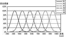
- FIG. 2 is a diagram illustrating the spectral sensitivity of each detection unit in the solar cell standard cell of the embodiment. The horizontal axis of FIG. 2 is the wavelength expressed in nm, and the vertical axis indicates the relative spectral sensitivity expressed in%.
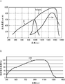
- FIG. 3 is a diagram illustrating spectral light receiving sensitivity of a photosensor used in each detection unit in the solar cell standard cell of the embodiment. 3A shows the spectral light receiving sensitivity of the Si photosensor, InGaAs photosensor, and Ge photosensor, and FIG. 3B shows the spectral light receiving sensitivity of the CIS photosensor.
- FIG. 3A shows the spectral light receiving sensitivity of the Si photosensor, InGaAs photosensor, and Ge photosensor
- FIG. 3B shows the spectral light receiving sensitivity of the CIS photosensor.
- the horizontal axis represents the wavelength expressed in nm
- the vertical axis represents the light receiving sensitivity expressed in mA / W.
- the horizontal axis in FIG. 3B is the wavelength expressed in nm
- the vertical axis is the relative light receiving sensitivity expressed in%.
- the standard cell for solar cell in the embodiment is a device that can be used as a so-called reference cell or pseudo cell of a solar cell. Therefore, the solar cell standard cell of the present embodiment can be used to adjust the amount of irradiation light of the solar simulator, for example, when evaluating solar cells indoors, and for example, evaluating solar cells outdoors. In this case, the measurement target solar cell can be juxtaposed, so that irradiation conditions in the measurement target solar cell can be actually monitored.
- a solar cell standard cell RC includes, for example, as shown in FIG. 1, a light receiving optical system 1, a plurality of detection units 2 (2-1 to 2-6), a preprocessing unit 3, and an arithmetic control.
- Unit 4 storage unit 5, operation input unit 6, output unit 7, and interface unit (hereinafter abbreviated as “IF unit” as appropriate) 8.
- the light receiving optical system 1 receives, as incident light, light emitted from a predetermined light source such as the sun, solar simulator (hereinafter abbreviated as “SS” where appropriate), electric lamp, LED, and fluorescent lamp. It is an optical system that makes the illumination light incident on each of the plurality of detection units 2. In the present embodiment, the light receiving optical system 1 causes illumination light to enter each of the plurality of detection units 2 with uniform illuminance.
- a predetermined light source such as the sun, solar simulator (hereinafter abbreviated as “SS” where appropriate)
- SS solar simulator
- electric lamp LED
- fluorescent lamp fluorescent lamp
- Such a light receiving optical system 1 is, for example, a bundle fiber.
- the bundle fiber includes a plurality of optical fibers, one end of the plurality of optical fibers is bundled into one, and the other end of the plurality of optical fibers is divided into a number corresponding to the number of the plurality of detection units 2. It is a bundled optical element.
- the one end of such a bundle fiber is an incident end to which irradiation light is incident, and the plurality of other ends are a plurality of emission ends from which irradiation light with uniform illuminance is emitted (emitted). .
- the illuminance is made uniform by repeating total reflection at the boundary between the core and the clad in the optical fiber while guiding the incident light from the incident end to the exit end.
- the light receiving optical system 1 is a glass member that diffuses and emits incident light.
- This glass member is, for example, an optical element in which unevenness of micron order is formed on at least one of an incident surface and an output surface by chemical treatment using a chemical solution capable of melting glass.
- the glass member is an optical element in which unevenness of micron order is formed on at least one of the entrance surface and the exit surface by, for example, sandblasting.
- Such a standard cell RC for solar cells uses a bundle fiber or a glass member having a diffusing function, so that the light receiving optical system 1 that radiates and distributes the irradiated light to a plurality with uniform illuminance is relatively simple. be able to.
- Each of the plurality of detection units 2 is a device that photoelectrically converts incident light and outputs it to the arithmetic control unit 4 via the preprocessing unit 3.
- Each spectral sensitivity (spectral light reception sensitivity) in the plurality of detection units 2 is Different from each other.
- the plurality of detection units 2 have the maximum sensitivity at different wavelengths. That is, the plurality of detection units 2 have different wavelengths with the maximum sensitivity.
- the plurality of detection units 2 are different from each other in the wavelength range of the full width at half maximum.
- the spectral sensitivities of the plurality of detection units 2 may overlap at a relatively small value.
- the number of detectors 2 is set to an appropriate number according to the specifications of the solar cell standard cell RC.
- each spectral sensitivity Ai (i is an integer from 1 to 6) in the six detectors 2-1 to 2-6 is shown in FIG. In the example shown in FIG.
- the first detector 2-1 has a spectral sensitivity A1 (thick solid line) that has the maximum sensitivity at a wavelength of about 390 nm
- the second detector 2-2 has a sensitivity at a wavelength of about 530 nm.
- the third detection unit 2-3 has the maximum spectral sensitivity A2 (the long dotted line), and the third detection unit 2-3 has the spectral sensitivity A3 (one-dot chain line) that has the maximum sensitivity at a wavelength of about 640 nm.
- spectral sensitivity A4 two-dot chain line
- the fifth detector 2-5 has a spectral sensitivity A5 (short dashed line) at which the sensitivity is maximum at a wavelength of about 890 nm
- the sixth detector 2-6 has a spectral sensitivity A6 (thin solid line) at which the sensitivity is maximum at a wavelength of about 1030 nm.
- Each of such a plurality of detection units 2 includes, for example, a filter unit 21 that transmits light in a predetermined wavelength range set in advance, and incident light incident through the filter unit 21 by photoelectric conversion. And a light receiving unit 22 that outputs an electrical signal corresponding to the light intensity of the light.
- the filter unit 21 is, for example, an absorptive optical filter that absorbs light in a wavelength range to be blocked out of incident light by a material having wavelength selectivity for light absorption, or a single layer or multiple layers (multiple layers) dielectric.
- an interference type optical filter that selects a wavelength that is transmitted by interference by the interference film.
- the light receiving unit 22 includes a Si photosensor using silicon (Si) as a material, a CIS photosensor using CIS as a material, a Ge photosensor using germanium (Ge) as a material, and gallium arsenide as a material.
- Si silicon
- CIS photosensor using CIS as a material
- Ge photosensor using germanium (Ge) as a material
- gallium arsenide as a material.
- a compound semiconductor photosensor using the above-described compound semiconductor such as (GaAs).
- the plurality of detection units 2 include an absorption type optical filter or an interference type optical filter, and a detection unit 2 according to a first aspect including a first photosensor having at least a light receiving sensitivity in the first wavelength band, and an absorption type optical filter or Of at least the first aspect of the detection part 2 of the second aspect, comprising: an interference optical filter; and a second photosensor having at least a light receiving sensitivity in a second wavelength band longer than the first wavelength band.
- a detection unit 2 is included. More specifically, each of the plurality of detection units 2 is configured by the detection unit of the first aspect.
- Such a solar cell standard cell RC can correspond to a solar cell to be measured having spectral sensitivity in the first wavelength band.
- the solar cell standard cell RC is within the range of spectral sensitivity of the Si photosensor (for example, a wavelength range of about 300 nm to about 1100 (see FIG. 3A)). It can correspond to a solar cell to be measured having spectral sensitivity.
- the solar cell standard cell RC is within the spectral sensitivity range of the CIS photosensor (for example, a wavelength range of about 300 nm to about 1300 (see FIG. 3B)).
- the plurality of detection units 2 include the detection unit of the first aspect and the detection unit of the second aspect.
- each of the first to fourth detection units 2-1 to 2-4 includes the detection unit of the first aspect, and the fifth and sixth detection units 2-5, 2- Each of 6 is comprised by the detection part of the said 2nd aspect.
- a standard cell RC for solar cells uses two types of photosensors, so that a first wavelength band (for example, a wavelength band of a relatively short wavelength) and a second wavelength band (for example, a relatively long wavelength). It is possible to correspond to a solar cell to be measured having a spectral sensitivity in the wavelength band.
- the spectral sensitivity of the infrared photosensor is within the range of the spectral sensitivity of the Si photosensor.
- the preprocessing unit 3 is a circuit that is connected to each of the plurality of detection units 2 and connected to the calculation control unit 4, performs a predetermined process on each output of the plurality of detection units 2, and outputs the result to the calculation control unit 4. is there.
- the predetermined processing includes, for example, amplification processing for amplifying the output of the detection unit 2 at a predetermined amplification factor, noise removal processing for removing noise from the output of the detection unit 2 subjected to amplification processing, and detection unit 2 for which noise removal processing has been performed.
- Analog-digital conversion processing AD conversion processing
- or the like for converting the output of the signal into a digital signal.
- the operation input unit 6 includes, for example, various commands such as a command for instructing measurement start, and input of an identifier (solar cell ID) in a solar cell to be measured, spectral sensitivity in the solar cell to be measured, A device for inputting various data necessary for calculating a predetermined evaluation value in the solar cell to be measured to the solar cell standard cell RC, for example, a plurality of input switches such as a numeric keypad.
- the spectral sensitivity of a solar cell is the photoelectric conversion efficiency at each wavelength of incident light in the solar cell, and is usually a unit of A / W (ampere / watt) as the output current of the solar cell with respect to the light energy incident on the solar cell.
- the output unit 7 is a device that outputs a command or data input from the operation input unit 6 and a predetermined evaluation value obtained by the standard cell RC for solar cells.
- a liquid crystal display (LCD) for example, a liquid crystal display (LCD), an organic EL display And a display device such as a plasma display and a printing device such as a printer.
- the IF unit 8 is a circuit for inputting / outputting data to / from an external device.
- an RS-232C interface circuit that is a serial communication system, an interface circuit using the Bluetooth (registered trademark) standard, an IrDA (Infrared)
- An interface circuit that performs infrared communication such as a Data Association standard, and an interface circuit that uses a USB (Universal Serial Bus) standard.
- Various data necessary for calculating a predetermined evaluation value in the solar cell to be measured is stored in the solar cell standard cell RC by using the IF unit 8. It may be entered.
- the operation input unit 6 includes a position input device that detects and inputs an operation position such as a resistive film method or a capacitance method
- the output unit 7 is a display device.
- a touch panel may be configured by the input device and the display device of the output unit 7.
- a position input device is provided on the display surface of the display device, one or more input content candidates that can be input to the display device are displayed, and the user touches the display position where the input content to be input is displayed. Then, the position is detected by the position input device, and the display content displayed at the detected position is input to the solar cell standard cell RC as the operation input content of the user.
- the position input device by changing display contents displayed on the display device, various input contents can be input, and various operations can be performed on the solar cell standard cell RC.
- the calculation control unit 4 controls each part of the solar cell standard cell RC according to the function of each part in order to obtain a predetermined evaluation value.
- the arithmetic control unit 4 includes, for example, a CPU (Central Processing Unit) and its peripheral circuits.
- the calculation control unit 4 is functionally configured with a control unit 41, a weight coefficient calculation unit 42, and an evaluation calculation unit 43 by executing a program.
- the control unit 41 controls the entire solar cell standard cell RC.
- the weighting factor calculation unit 42 is configured so that the sum of the multiplication results obtained by multiplying the spectral sensitivities Ai of the plurality of detection units 2 by the respective weighting factors Ci matches the spectral sensitivities of the solar cells to be measured. Ci is calculated.
- the evaluation calculation unit 43 receives the irradiation light from a predetermined light source by the plurality of detection units 2 and outputs the output Bi in the plurality of detection units 2 and the weight coefficient Ci calculated by the weight coefficient calculation unit 42. Based on the above, a predetermined evaluation value in the solar cell to be measured is calculated.
- the storage unit 5 is a non-volatile storage element such as a ROM (Read Only Memory) or an EEPROM (Electrically Erasable Programmable Read Only Memory) that stores various programs executed by the arithmetic control unit 4 and data necessary for the execution.
- a volatile storage element such as a RAM (Random Access Memory) serving as a so-called working memory of the arithmetic control unit 4 and its peripheral circuit are provided.
- the storage unit 5 is functionally configured with a spectral sensitivity storage unit 51 for storing spectral sensitivity and a weighting factor storage unit 52 for weighting coefficients.
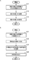
- FIG. 4 is a flowchart showing the operation of the solar cell standard cell in the embodiment.
- 4A is a flowchart showing the weighting factor calculation process
- FIG. 4B is a flowchart showing the evaluation calculation process.
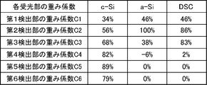
- FIG. 5 is a diagram illustrating weighting factors stored in the storage unit in the solar cell standard cell of the embodiment.
- FIG. 6 is a diagram showing the spectral sensitivity of the crystalline silicon solar cell and the spectral sensitivity of the crystalline silicon solar cell in the solar cell standard cell of the embodiment.
- FIG. 7 is a diagram showing the spectral sensitivity of an amorphous silicon solar cell and the spectral sensitivity of a crystalline silicon solar cell in the solar cell standard cell of the embodiment.
- FIGS. 6 to 8 is a diagram illustrating the spectral sensitivity of the dye-sensitized solar cell and the spectral sensitivity of the crystalline silicon solar cell in the solar cell standard cell of the embodiment.
- Each horizontal axis in FIGS. 6 to 8 represents a wavelength expressed in nm, and each vertical axis represents relative spectral sensitivity expressed in%.
- the solar cell standard cell RC in the present embodiment generally performs a weighting factor calculation process for obtaining the weighting factor Ci and an evaluation calculation process for obtaining a predetermined evaluation value using the obtained weighting factor Ci.
- a weighting factor calculation process for obtaining the weighting factor Ci
- an evaluation calculation process for obtaining a predetermined evaluation value using the obtained weighting factor Ci.
- the spectral sensitivity of the solar cell to be measured is input from the operation input unit 6 or the IF unit 8 to the solar cell standard cell RC (S11).
- the spectral sensitivity input from the operation input unit 6 or the IF unit 8 is each spectral sensitivity in a plurality of different types of solar cells, and the spectral sensitivity storage unit 51 identifies and identifies the solar cells.
- the spectral sensitivity of the solar cell is stored in association with the identifier (solar cell ID).
- the weighting factor calculation unit 42 calculates the weighting factor Ci for each of the plurality of solar cells (S12). Since the spectral sensitivities of the plurality of solar cells are stored in the spectral sensitivity storage unit 51, the spectral sensitivity to be calculated for the weight coefficient Ci is selected from the plurality of spectral sensitivities of the plurality of solar cells. 6 may be specified.
- the weighting factor Ci may be obtained by using a so-called principal component analysis. Further, for example, the square of the difference between the combined spectral sensitivity and the spectral sensitivity of the solar cell to be measured may be obtained for each wavelength, and the weighting coefficient Ci may be obtained so that the sum is minimized.
- the combined spectral sensitivity at the wavelength ⁇ i is Sref ( ⁇ i)
- the spectral sensitivity in the solar cell to be measured at the wavelength ⁇ i is RSSs ( ⁇ i)
- the operator that minimizes x is min (x)
- the combined spectral sensitivity is a sum of multiplication results obtained by multiplying each spectral sensitivity Ai of each detection unit 2 by a weighting factor Ci (weighting factor Ci in the middle of calculation).
- the weighting factor calculation unit 42 is a predetermined error that is set in advance in the spectral sensitivity of the solar cell to be measured, as the sum of the multiplication results obtained by multiplying the spectral sensitivities Ai in the plurality of detection units 2 by the respective weighting factors Ci.
- the weighting factors Ci may be calculated so as to match within the range.
- the predetermined error range is appropriately set according to the specifications of the solar cell standard cell RC. The smaller the predetermined error range, the higher the combined spectral sensitivity, which is the sum of each multiplication result obtained by multiplying each spectral sensitivity Ai of each detector 2 by each weighting factor Ci, closer to the spectral sensitivity of the solar cell to be measured.
- the solar cell standard cell RC can calculate a predetermined evaluation value with high accuracy.
- the weighting factor calculation unit 42 determines whether or not the error of the combined spectral sensitivity using the weighting factor Ci thus obtained with respect to the spectral sensitivity of the solar cell to be measured is within the predetermined error range. The validity of the heavy coefficient Ci may be determined.
- the weighting factor calculation unit 42 stores the weighting factors Ci for the plurality of calculated solar cells in the weighting factor storage unit 52 in association with the solar cell ID (S13).
- the weight coefficient storage unit 52 stores weight coefficients for a plurality of solar cells in a table format.
- the table stores fields for storing the weighting factors C1 to C6 of the crystalline silicon solar cell (c-Si) and the weighting factors C1 to C6 of the amorphous silicon solar cell (a-Si).
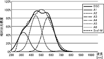
- FIG. 6 also shows the spectral sensitivities A1 to A6 of the detectors 2-1 to 2-6 multiplied by the obtained weighting factors C1 to C6, and the combined spectral sensitivity Sref-M that is the sum of these spectral sensitivities. Is also illustrated.
- the spectral sensitivity of the solar cell to be measured is indicated by the thickest solid line
- the spectral sensitivity A1 of the detector 2-1 multiplied by the weighting coefficient C1 is indicated by the next thickest solid line
- the weighting coefficient C2 is The spectral sensitivity A2 of the detection unit 2-2 multiplied is indicated by a long dashed line
- the spectral sensitivity A3 of the detection unit 2-3 multiplied by the weighting factor C3 is indicated by a one-dot chain line
- the detection unit multiplied by the weighting factor C4 The spectral sensitivity A4 of 2-4 is indicated by a two-dot chain line
- the spectral sensitivity A5 of the detection unit 2-5 multiplied by the weighting coefficient C5 is indicated by a short dashed line
- the detection unit 2-2 multiplied by the weighting coefficient C6 Is shown by a thin solid line
- the combined spectral sensitivity Sref-M is shown by a thick broken line.
- the weighting factors C1 to C6 are 46%, 100%, 38%, -6%, 0%, and 0% in order.
- FIG. 7 also shows the spectral sensitivities A1 to A6 of the detectors 2-1 to 2-6 multiplied by the obtained weighting factors C1 to C6, and the combined spectral sensitivity Sref-M, which is the sum of them. Is also illustrated.
- the weighting factors C1 to C6 are 46%, 86%, 83%, 2%, 0%, and 0% in order.
- FIG. 8 also shows the spectral sensitivities A1 to A6 of the detectors 2-1 to 2-6 multiplied by the obtained weighting factors C1 to C6, and the combined spectral sensitivity Sref-M that is the sum of them. Is also illustrated.
- the solar cell standard cell RC can obtain the weighting factor Ci for the solar cell to be measured.
- the type of solar cell selected as a measurement target from the plurality of solar cells is input from the operation input unit 6 (S21). More specifically, a solar cell ID selected as a measurement target is input from the operation input unit 6.
- Irradiation light from a predetermined light source is incident on the light receiving optical system 1 of the standard cell RC for solar cells. Irradiation light incident on the light receiving optical system 1 is made uniform in illuminance by the light receiving optical system 1 and then incident on each of the detection units 2-1 to 2-6.
- Each of the detectors 2-1 to 2-6 receives the irradiated light with the spectral sensitivity of the detector 2 and performs photoelectric conversion.
- Each of the detection units 2-1 to 2-6 outputs the result of the photoelectric conversion to the arithmetic control unit 4 via the preprocessing unit 4 (S22).
- the evaluation calculation unit 43 of the calculation control unit 4 calculates the input solar cell ID, that is, an evaluation value for the type of the solar cell to be measured. (S23), the evaluation value of the calculation result is output to the output unit 7 (S24). More specifically, in this embodiment, the evaluation calculation unit 43 of the calculation control unit 4 multiplies each output Bi in each of the plurality of detection units 2 by each weight coefficient Ci, and the sum of these multiplication results is calculated by the solar cell.
- the output unit 7 displays the short-circuit current Isc, for example.
- the solar cell standard cell RC can obtain an evaluation value such as a short-circuit current for the solar cell to be measured.
- each weighting factor Ci is calculated by the weighting factor calculation unit 42, whereby each spectral sensitivity Ai in the plurality of detection units 2 is multiplied by each weighting factor Ci.
- Synthetic spectral sensitivity Sref can be adjusted to the spectral sensitivity of the solar cell to be measured.
- the standard cell RC for solar cells in this embodiment can change each weighting coefficient Ci according to the kind of solar cell of a measuring object, in arbitrary spectral irradiance in arbitrary light sources, it is one and plural It can be used for various types of solar cells.
- the standard cell RC for solar cells in this embodiment is matched with the spectral sensitivity in the solar cell to be measured, it is used not only indoors but also outdoors, so that it is more than when using a pyranometer.
- the solar cell can be accurately evaluated.
- the solar cell standard cell RC in the present embodiment can calculate and store the weighting factors Ci in a plurality of types of solar cells in the weighting factor storage unit 52, and select the type of solar cell to be measured. By inputting from the operation input unit 6, an evaluation value such as a short-circuit current of the solar cell to be measured can be easily calculated.
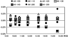
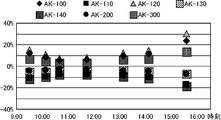
- FIG. 9 is a diagram showing a measurement error in the solar cell standard cell of the embodiment as one experimental result.
- the horizontal axis in FIG. 9 is time, and the vertical axis is a measurement error expressed in%.
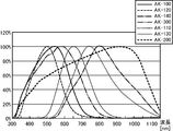
- FIG. 10 is a diagram showing the spectral sensitivities of a plurality of solar cells.
- the horizontal axis in FIG. 10 is the wavelength expressed in nm, and each vertical axis indicates the relative spectral sensitivity expressed in%.
- FIG. 11 is a diagram showing sunlight at various times in the range from 9:30 to 15:30 and the spectral irradiance of AM1.5G defined by IEC.
- FIG. 11 is the wavelength expressed in nm, and each vertical axis is the spectral irradiance.
- FIG. 12 is a diagram showing a measurement error of the pyranometer of the comparative example as one experimental result.
- the horizontal axis in FIG. 12 is time, and the vertical axis is a measurement error expressed in%.
- the solar cell to be measured is a solar cell having the spectral sensitivity shown in FIG. More specifically, solar cell AK-100 (thick solid line), solar cell AK-120 (long dotted line), and relative spectral sensitivity are maximized at a relatively short wavelength with respect to a wavelength range of 300 nm to 1100 nm.
- Solar cell AK-300 (dashed line), solar cell AK-130 (thin solid line) and solar cell AK-110 (short dotted line) having a relative spectral sensitivity at a maximum value at a relatively medium wavelength
- a solar cell AK-140 one-dot chain line
- a solar cell AK-200 (long dotted thick dotted line) having a relative spectral sensitivity having a maximum value at a relatively long wavelength.
- the irradiation light is between 9:30 and 15:30 in January, 9:30, 10: 9, 10:40, 11:45, 13: 9, 14: 9
- sunlight at each time of 15:37 has the spectral irradiance shown in FIG.
- FIG. 10 also shows the spectral irradiance of AM1.5G defined by IEC.
- the solar cell standard cell RC of the above-described embodiment was used for such a measurement target solar cell and irradiation light, and a solarimeter having a certain spectral sensitivity was used as an example for comparison. .
- FIGS. 9 and 12 show the measurement error of the short-circuit current, which is the difference between the short-circuit current of each solar battery obtained by the solar cell standard cell RC of the embodiment and the short-circuit current of each solar battery obtained from FIG. 10 and FIG.
- FIG. 12 shows the measurement error of the short-circuit current, which is the difference between the short-circuit current of each solar cell determined by the pyranometer of the comparative example and the short-circuit current of each solar cell determined from FIG. 10 and FIG. .
- ⁇ indicates the measurement error of solar cell AK-100
- ⁇ indicates the measurement error of solar cell AK-110
- ⁇ hatched with a dot indicates measurement of solar cell AK-120
- ⁇ hatched with diagonal lines indicates the measurement error of the solar cell AK-130
- ⁇ hatched with the grid indicates the measurement error of the solar cell AK-140
- ⁇ indicates the solar cell AK-
- a square error of 200 indicates a measurement error of the solar cell AK-300.
- the short-circuit current Isc of the solar cell can be obtained by ⁇ S ( ⁇ ) ⁇ E ( ⁇ ) d ⁇ .
- the solar cell standard cell RC of the present embodiment is remarkably highly accurate compared to the case of the pyranometer.
- the short circuit current of the solar cell can be obtained.
- the solar cell standard cell RC responds to the bias current by the DSR method (differential spectral responsivity method, absolute spectral sensitivity method) based on a plurality of spectral sensitivities, as shown by the broken lines in FIG.
- the calculation control unit 4 may further include an absolute value spectral sensitivity calculation unit 44 that calculates the absolute value spectral sensitivity (absolute spectral sensitivity).
- the spectral sensitivities input to the operation input unit 6 or the IF unit 8 are a plurality of spectral sensitivities corresponding to different bias currents, and when the plurality of spectral sensitivities are input, the operation input unit 6 or IF
- the unit 8 further receives a bias current corresponding to the spectral sensitivity, and the weighting factor calculator 42 calculates the absolute value spectrum calculated by the absolute value spectral sensitivity calculator 44 as the spectral sensitivity of the solar cell to be measured.
- Each weighting factor Ci is calculated by using sensitivity (absolute spectral sensitivity).
- the absolute value spectral sensitivity is the spectral sensitivity of the solar cell for each irradiance.
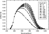
- FIG. 13 is a diagram showing each spectral sensitivity for each bias current in the case of a microcrystalline silicon solar cell as an example.
- the horizontal axis of FIG. 13 is the wavelength expressed in nm unit, and the vertical axis is the absolute value spectral sensitivity (DSR) expressed in A / W unit.
- FIG. 13 shows bias currents of 0 mA ( ⁇ ), 10 mA ( ⁇ ), 50 mA (upward one vertex), 100 mA (downward one vertex ( ⁇ )), 200 mA ( ⁇ ), 400 mA (one vertex leftward).
- each spectral sensitivities in each case of ⁇ ), 800 mA ( ⁇ directed to the right of one vertex), 1600 mA ( ⁇ ), and 2500 mA ( ⁇ ) are shown.
- each spectral sensitivity is calculated
- the DSR method is, for example, Document 1 “J. Metzdorf,“ Calibration of solar cells 1: The differential spectral response method ”, 1 May 1987 / Vol. 26 No. 2 170 Ops. , T. Wittchen, J. Metzdorf, “Primary Reference Cell Calibration at the PTB based on an Improved DSR Facility”, 16th European PhotovoltagenicSolventerGoldSolventerGoldSolventerGoldSolventerGoldSolventerGoldSports Patent is a known technique disclosed in 2012-39036 Patent Publication.
- the solar cell In the measurement of the absolute value spectral sensitivity by the DSR method, the solar cell is generally in a power generation state (biased state (bias state)) by irradiating the solar cell to be measured with white light as a bias light. By further irradiating the solar cell with the monochromatic light in the bias state, the sensitivity (output current) at the wavelength of the monochromatic light is measured. While changing the wavelength of the monochromatic light superimposed on the bias light, each output current in the solar cell to be measured is measured, and the spectral sensitivity of the solar cell at the illuminance of the bias light is measured. The measurement is similarly performed by changing the illuminance of the bias light, and each spectral sensitivity of the solar cell at each illuminance is measured.
- the absolute value spectral sensitivity of a solar cell is calculated by DSR method based on each spectral sensitivity of the solar cell in each illuminance.
- the spectral sensitivity from each illuminance to the differential spectral sensitivity (changes in short-circuit current with respect to illuminance minute change ⁇ E ⁇ Isc, ⁇ Isc / ⁇ E) is obtained, and the absolute value spectral sensitivity at the measurement illuminance can be obtained from this value and the short-circuit current.
- the standard cell for a solar cell includes an input unit to which spectral sensitivity in a solar cell to be measured is input, a plurality of detection units that have different spectral sensitivities, photoelectrically convert incident light, and A weighting factor calculation unit that calculates each weighting factor so that the sum of the multiplication results obtained by multiplying each spectral sensitivity in each of the plurality of detection units by each weighting factor matches the spectral sensitivity in the solar cell to be measured; The sun of the measurement object based on each output in the plurality of detection units obtained by receiving light emitted from a predetermined light source by the plurality of detection units and each weighting factor calculated by the weighting factor calculation unit And an evaluation calculation unit that calculates a predetermined evaluation value in the battery.
- Such a standard cell for a solar cell calculates the sum of each multiplication result obtained by multiplying each spectral coefficient in each of the plurality of detection units by each weight coefficient by calculating each weight coefficient by the weight coefficient calculation unit.
- the spectral sensitivity of the solar cell to be measured can be adjusted.
- such a standard cell for a solar cell can change each of the weighting factors according to the type of solar cell to be measured, and thus can support a plurality of types of solar cells at a given spectral irradiance. it can.
- such a solar cell standard cell can be used not only indoors but also outdoors, so that solar cells can be evaluated more accurately than when using a pyranometer.
- the standard cell is a device having a spectral sensitivity similar to that of the solar cell to be measured, and includes functions similar to those of the reference cell and the pseudo cell.
- Types of solar cells are classified according to materials such as silicon solar cells, compound solar cells, organic solar cells, and forms such as thin film silicon solar cells, hybrid solar cells, tandem solar cells, etc.
- the classification according to the product name with the same material, the classification according to the product name with the same form, and the classification according to the lot with the same product name are included.
- the type of solar cell means a classification according to the spectral sensitivity, and is different if the spectral sensitivity is different.
- the spectral sensitivity input to the input unit is a plurality of spectral sensitivities corresponding to different bias currents, and is based on the plurality of spectral sensitivities.
- an absolute value spectral sensitivity calculation unit that calculates an absolute value spectral sensitivity according to the bias current by a DSR method (differential spectral responsivity method) is further provided, and the weighting factor calculation unit is a spectral sensitivity in the solar cell to be measured. The absolute value spectral sensitivity calculated by the absolute value spectral sensitivity calculation unit is used.
- Such a standard cell for a solar cell obtains an absolute value spectral sensitivity by a so-called DSR method, and therefore can be used for a solar cell whose spectral sensitivity changes nonlinearly according to illuminance.
- the above-described standard cell for solar cell further includes a storage unit that stores the weighting coefficient, and the spectral sensitivity input to the input unit includes a plurality of different types of solar cells.
- the weighting factor calculation unit calculates the weighting factor for each of the plurality of solar cells
- the storage unit calculates the weighting factor in association with the plurality of solar cells.
- the weighting coefficient for the plurality of solar cells calculated by the unit is stored, and the input unit is further inputted with a type of solar cell selected as a measurement target from the plurality of solar cells, and the evaluation calculation The unit calculates the evaluation value for the type of the solar cell to be measured, which is input to the input unit.
- Such a standard cell for a solar cell calculates and stores each weighting factor in a plurality of types of solar cells, and selects and inputs the type of solar cell to be measured, thereby easily evaluating the solar cell to be measured. Can be calculated.
- the plurality of detection units have an optical filter and a light receiving sensitivity at least in the first wavelength band, and photoelectrically convert incident light to be output.
- a detection unit of the first aspect including one photosensor; an optical filter; and at least a light receiving sensitivity in a second wavelength band longer than the first wavelength band, and photoelectrically converting incident light to be output.
- the detection part of the said 1st aspect is included at least among the detection parts of a 2nd aspect provided with a 2nd photosensor.
- the first photosensor is preferably a Si photosensor or a CIS (including copper, copper, indium, and selenium).
- the second photosensor is preferably an infrared photosensor, and the infrared photosensor is preferably a photosensor made of any one of GaAs, InGaAs, GaAsP, GaP, PbS, and PbSe.
- Such a standard cell for a solar cell can correspond to a solar cell to be measured having spectral sensitivity in the first wavelength band by configuring the plurality of detection units with the detection unit of the first aspect.
- Such a standard cell for a solar battery includes a first wavelength band (for example, a wavelength band of a relatively short wavelength) by configuring the plurality of detection units with the detection units of the first and second aspects, and This can correspond to a solar cell to be measured having spectral sensitivity in the second wavelength band (for example, a wavelength band having a relatively long wavelength).
- the above-described standard cell for solar cell further includes a light receiving optical system that causes the irradiation light from the predetermined light source to enter each of the plurality of detection units with uniform illuminance. It is done.
- Such a standard cell for a solar cell includes a light receiving optical system that makes the illuminance uniform, so that irradiation light can be uniformly incident on each detection unit, and the solar cell can be evaluated more accurately.
- the light receiving optical system includes a plurality of optical fibers, and bundles one end of the plurality of optical fibers into one, A bundle fiber in which the other end is bundled by being divided into a number corresponding to the number of the plurality of detection units.
- Such a standard cell for a solar battery can constitute the light receiving optical system relatively easily by using a bundle fiber.
- the light receiving optical system is a glass member that diffuses and emits incident light.
- the glass member is preferably an optical element in which unevenness of micron order is formed on at least one of the entrance surface and the exit surface by chemical treatment using a chemical solution capable of melting glass.
- the glass member is an optical element in which unevenness of micron order is formed on at least one of an incident surface and an output surface by, for example, sandblasting.
- Such a solar cell standard cell can constitute the light receiving optical system relatively easily by using a glass member having a diffusion function.
- a standard cell for a solar battery can be provided.
Landscapes
- Physics & Mathematics (AREA)
- Spectroscopy & Molecular Physics (AREA)
- General Physics & Mathematics (AREA)
- Photovoltaic Devices (AREA)
- Photometry And Measurement Of Optical Pulse Characteristics (AREA)
- Spectrometry And Color Measurement (AREA)
Abstract
本発明の太陽電池用標準セルでは、複数の検出部における各分光感度に各重み係数をそれぞれ乗算した各乗算結果の総和が測定対象の太陽電池における分光感度に一致するように、前記各重み係数が演算され、所定の光源からの照射光を前記複数の検出部で受光することによって得られた前記複数の検出部における各出力と前記演算された各重み係数に基づいて前記測定対象の太陽電池における所定の評価値が演算される。
Description
本発明は、1台で複数の太陽電池の基準セルや擬似セル等として用いることができる太陽電池用標準セルに関する。
太陽電池は、光起電力効果を利用することによって光エネルギーを直接電力へ変換する素子であり、様々な太陽電池が研究、開発され、近年、広く普及し始めている。この太陽電池(以下、適宜「PV」と略記する)には、シリコン(Si)を用いたシリコン系PV、InGaAs等の化合物半導体を用いた化合物系PVおよび有機半導体を用いた有機系PV等の様々な種類があり、有機系PVには、2種類の有機半導体を用いてPN接合を形成しPN接合における電子の光励起によって光起電力を得るPN接合型PVと、有機色素中の電子の光励起によって光起電力を得る色素増感太陽電池とがある。
このようなPVの性能を評価するために、例えばIEC60904やJIS C8905~C8991等で定義された評価方法がある。なお、IECは、International Electrotechnocal Commission(国際電気標準会議)の略称であり、JISは、Japanese Industrial Standards(日本工業規格)の略称である。PVの発電定格は、上記規約で国際的に統一された標準試験条件(Standard Test Condition、STC)として規定されている。この標準試験条件は、温度25℃、放射照度1000W/m2、AM1.5Gの基準太陽光である。測定では、基準太陽光のスペクトルに近似した光を照射するいわゆるソーラシミュレータ(以下、適宜「SS」と略記する。)の照射位置に測定対象のPVが配置され、このPVの温度が25℃となるように管理され、PVの発電定格が測定されている(例えば特許文献1、非特許文献1参照)。ここで、基準太陽光のスペクトルとSSのスペクトルとの間に差があると、測定されたPVの発電定格に誤差が含まれることになる。このため、SSのスペクトルは、基準太陽光のスペクトルに高度に近似していることが望ましい。しかしながら、基準太陽光のスペクトルは、複雑であり、基準太陽光のスペクトルに高度に近似したSSは、技術的に難しく、高価となってしまう。
そこで、現在では、多くの場合、以下のようにして、SSが校正されている。まず、測定者は、例えば、産業技術総合技術研究所(=国際的に統一された基準太陽光スペクトル等を持っている国立またはそれに準じる機関)に、評価対象のPVと同様の分光感度特性を有するPVをサンプルとして送付してその測定を依頼する。それに応じて該機関は、所有している限りなく基準太陽光に近い高近似のSSを用いることによって、標準試験条件で前記サンプルの短絡電流Iscを求め、その測定値(=A)を前記測定者に返送する。これを受けて前記測定者は、返送されて来た前記サンプルを、以降、自社の基準セルとして、SSの光量調整用に使用している。すなわち、前記測定者は、前記基準セルを用いて、その短絡電流IscがAとなるように、SSの光量を調整してから、実際に測定(評価)すべき(検査対象の製品の)PVの特性を測定している。
なお、基準セルは、例えばJIS C8904に規定されており、その1つに「基準セルは、測定しようとするPVと同じ分光感度を有すること」という要求項目がある。このため、結晶系のPVの場合では、分光感度を同じにするために一群のPVの中から1つを選んで基準セルが作成されている。しかしながら、結晶系のPVではない例えばアモルファス系のPVや色素増感PV等の場合、PV自体の特性が変化してしまうため、それを基準セルとして使用することは、安定性に欠ける。このため、このような種類のPVの場合、測定対象のPVの分光感度と同じ分光感度を持つように、結晶シリコン系PVに光学フィルタを用いた擬似セルの使用が認められている。このようにSSを光源とし、SSの光量調整後にPVの性能が評価されているが、この評価方法は、屋内で測定することを前提としている。
一方、近年の固定買取制度(Feed-in Tariff)の導入により、標準試験条件という特定の条件による評価だけでなく、年間発電量が重要視されるようになってきている。このため、屋外におけるPVの性能劣化状況を推定するために、屋外におけるPVへの照射条件をモニタすることも重要となってきている。
すなわち、PVの設置場所では、PVの温度、太陽の放射照度および太陽の放射照度スペクトルがそれぞれ時々刻々と様々に変化する。このため、これらの因子をより正確に測定する必要がある。そして、PVは、使用に伴い性能が劣化する。この劣化状況を正確に調べるために、PVの発電量をモニタするだけではなく、照射条件を正確に測定することによって、PVの劣化によるものか、照射条件の影響によるものかに、原因を分けて、発電量の低下を評価する必要がある。
ところで、上記屋内における太陽電池の評価では、基準セルおよび擬似セルを測定対象の太陽電池の種類ごとに作成する必要があり、さらに、基準セルおよび擬似セルごとに前記公的機関で前記測定値Aを測定してもらう必要がある。このため、手間、費用および期間が掛かってしまう。
一方、上記屋外におけるPVの評価では、照射条件をモニタするために、測定対象の太陽電池のそばに、基準セルや擬似セルを並置することが考えられる。これによって前記測定対象の太陽電池における照射条件を実際にモニタすることが可能となる。しかしながら、この場合では、基準セルや擬似セルを必要とするため、上記屋内評価と同様な事情となり、手間、費用および期間が掛かってしまう。
また、照射条件をモニタするために、分光型日射計を用いることが考えられるが、この分光型日射計は、比較的高価であり、また、使用温度範囲が狭いという性能上の不都合もあるため、普及してない。その代わりに、現状では、日射計が用いられている。しかしながら、日射計は、相対分光感度が波長に依存せずに一定である一方、太陽電池の分光感度は、波長に依存している。このため、この日射計では、太陽電池の評価に大きな誤差が含まれてしまう。
Kiyoshi Imai,Yoshihiro Nishikawa,et al,"Application of Spectral Reference Cell to Non-Linear Photovoltaic Cells",27th Euripean Photovoltaic Solar Energy Conference and Exhivition(2012),4BV.4.40
本発明は、上述の事情に鑑みて為された発明であり、その目的は、1個で複数の種類の太陽電池に対応することができる太陽電池用標準セルを提供することである。
本発明にかかる太陽電池用標準セルでは、複数の検出部における各分光感度に各重み係数をそれぞれ乗算した各乗算結果の総和が測定対象(評価対象)の太陽電池における分光感度に一致するように、前記各重み係数が演算され、所定の光源からの照射光を前記複数の検出部で受光することによって得られた前記複数の検出部における各出力と前記演算された各重み係数に基づいて前記測定対象の太陽電池における所定の評価値が演算される。このため、本発明にかかる太陽電池用標準セルは、前記測定対象の太陽電池の種類に応じて前記各重み係数を変更できるので、任意の分光放射照度において、1個で複数の種類の太陽電池に対応できる。
上記並びにその他の本発明の目的、特徴及び利点は、以下の詳細な記載と添付図面から明らかになるであろう。
以下、本発明にかかる実施の一形態を図面に基づいて説明する。なお、各図において同一の符号を付した構成は、同一の構成であることを示し、適宜、その説明を省略する。また、本明細書において、総称する場合には添え字を省略した参照符号で示し、個別の構成を指す場合には添え字を付した参照符号で示す。
(実施形態の構成)
図1は、実施形態における太陽電池用標準セルの構成を示すブロック図である。図2は、実施形態の太陽電池用標準セルにおける各検出部の分光感度を示す図である。図2の横軸は、nm単位で表す波長であり、その縦軸は、%単位で表す相対分光感度を示す。図3は、実施形態の太陽電池用標準セルにおける各検出部に用いられるフォトセンサの分光受光感度を示す図である。図3Aは、Siフォトセンサ、InGaAsフォトセンサおよびGeフォトセンサの各分光受光感度を示し、図3Bは、CISフォトセンサの分光受光感度を示す。図3Aの横軸は、nm単位で表す波長であり、その縦軸は、mA/W単位で表す受光感度である。図3Bの横軸は、nm単位で表す波長であり、その縦軸は、%で表す相対受光感度である。
図1は、実施形態における太陽電池用標準セルの構成を示すブロック図である。図2は、実施形態の太陽電池用標準セルにおける各検出部の分光感度を示す図である。図2の横軸は、nm単位で表す波長であり、その縦軸は、%単位で表す相対分光感度を示す。図3は、実施形態の太陽電池用標準セルにおける各検出部に用いられるフォトセンサの分光受光感度を示す図である。図3Aは、Siフォトセンサ、InGaAsフォトセンサおよびGeフォトセンサの各分光受光感度を示し、図3Bは、CISフォトセンサの分光受光感度を示す。図3Aの横軸は、nm単位で表す波長であり、その縦軸は、mA/W単位で表す受光感度である。図3Bの横軸は、nm単位で表す波長であり、その縦軸は、%で表す相対受光感度である。
実施形態における太陽電池用標準セルは、太陽電池のいわゆる基準セルや擬似セルとして用いることができる装置である。したがって、本実施形態の太陽電池用標準セルは、例えば、屋内における太陽電池の評価の際に、ソーラシミュレータの照射光量を調整するために使用することができ、また例えば、屋外における太陽電池の評価の際に、測定対象の太陽電池のそばに並置することができ、これによって前記測定対象の太陽電池における照射条件を実際にモニタすることもできる。このような太陽電池用標準セルRCは、例えば、図1に示すように、受光光学系1と、複数の検出部2(2-1~2-6)と、前処理部3と、演算制御部4と、記憶部5と、操作入力部6と、出力部7と、インターフェース部(以下、適宜「IF部」と略記する。)8とを備える。
受光光学系1は、例えば太陽、ソーラシミュレータ(以下、適宜「SS」と略記する。)、電灯、LEDおよび蛍光灯等の所定の光源から放射された光が照射光として入射され、この入射された照明光を、複数の検出部2のそれぞれへ入射させる光学系である。本実施形態では、受光光学系1は、照明光を、照度を均一にして複数の検出部2のそれぞれへ入射させる。
このような受光光学系1は、例えば、バンドルファイバである。このバンドルファイバは、複数の光ファイバを備え、前記複数の光ファイバにおける一方端を一つに束ね、前記複数の光ファイバにおける他方端を複数の検出部2の個数に応じた個数に分けてそれぞれ束ねた光学素子である。このようなバンドルファイバの前記一方端は、照射光が入射される入射端とされ、前記複数の他方端は、照度を均一にした照射光が出射(射出)される複数の出射端とされる。バンドルファイバでは、入射光を入射端から出射端へ導光する間に、光ファイバにおけるコアとクラッドとの境界で全反射を繰り返すことによって照度が均一化される。また例えば、受光光学系1は、入射光を拡散して出射するガラス部材である。このガラス部材は、例えば、ガラスを溶かすことができる薬液を用いた化学処理によってミクロンオーダーの凹凸を入射面および出射面のうちの少なくとも一方に形成した光学素子である。また例えば、前記ガラス部材は、例えばサンドブラスト等によってミクロンオーダーの凹凸を入射面および出射面のうちの少なくとも一方に形成した光学素子である。このような太陽電池用標準セルRCは、バンドルファイバあるいは拡散機能を有するガラス部材を用いることによって、照射光を均一な照度で複数に分配して出射する受光光学系1を比較的簡単に構成することができる。
複数の検出部2は、それぞれ、入射光を光電変換して前処理部3を介して演算制御部4へ出力する装置であり、複数の検出部2における各分光感度(分光受光感度)は、互いに異なる。複数の検出部2は、互いに異なる波長で感度が最大となる。すなわち、複数の検出部2は、最大感度の波長が互いに異なる。複数の検出部2は、半値全幅の波長範囲が互いに異なる。複数の検出部2の分光感度は、比較的小さい値の部分で重なってもよい。検出部2の個数は、当該太陽電池用標準セルRCの仕様に応じて適宜な個数に設定される。検出部2の個数は、多いほど、当該太陽電池用標準セルRCの分光感度を、測定対象の太陽電池の分光感度に高精度で一致(近似)させることができ、好ましい。一方、検出部2の個数は、少ないほど、当該太陽電池用標準セルRCの構成が簡素化され、低コスト化を図ることができ、好ましい。本実施形態では、検出部2は、6個である。これら6個の検出部2-1~2-6における各分光感度Ai(i=1~6の整数)の一例が図2に示されている。図2に示す例では、第1検出部2-1は、波長約390nmで感度が最大となる分光感度A1(太い実線)を持ち、第2検出部2-2は、波長約530nmで感度が最大となる分光感度A2(長い点の破線)を持ち、第3検出部2-3は、波長約640nmで感度が最大となる分光感度A3(一点鎖線)を持ち、第4検出部2-4は、波長約770nmで感度が最大となる分光感度A4(二点鎖線)を持ち、第5検出部2-5は、波長約890nmで感度が最大となる分光感度A5(短い点の破線)を持ち、そして、第6検出部2-6は、波長約1030nmで感度が最大となる分光感度A6(細い実線)を持つ。
このような複数の検出部2のそれぞれは、例えば、予め設定された所定の波長範囲の光を透過するフィルタ部21と、フィルタ部21を介して入射された入射光を光電変換して入射光の光強度に応じた電気信号を出力する受光部22とを備える。フィルタ部21は、例えば、光の吸収に波長選択性を持つ材料によって、入射光のうち、遮光する波長範囲の光を吸収する吸収型光学フィルタや、1層または多層(複数層)の誘電体の干渉膜による干渉によって透過する波長を選択する干渉型光学フィルタ等である。受光部22は、材料としてシリコン(Si)を用いたSiフォトセンサや、材料として上述のCISを用いたCISフォトセンサや、材料としてゲルマニウム(Ge)を用いたGeフォトセンサや、材料としてガリウムヒ素(GaAs)等の上述の化合物半導体を用いた化合物半導体のフォトセンサ等である。
複数の検出部2は、吸収型光学フィルタまたは干渉型光学フィルタと、第1波長帯域に少なくとも受光感度を持つ第1フォトセンサとを備える第1態様の検出部2、および、吸収型光学フィルタまたは干渉型光学フィルタと、前記第1波長帯域よりも長波長側の第2波長帯域に少なくとも受光感度を持つ第2フォトセンサとを備える第2態様の検出部2のうちの少なくとも前記第1態様の検出部2を含む。より具体的には、複数の検出部2のそれぞれは、前記第1態様の検出部で構成される。このような太陽電池用標準セルRCは、第1波長帯域で分光感度を持つ測定対象の太陽電池に対応することができる。例えば、第1フォトセンサがSiフォトセンサである場合には、太陽電池用標準セルRCは、Siフォトセンサの分光感度の範囲(例えば波長約300nm~約1100の範囲(図3A参照))内で分光感度を持つ測定対象の太陽電池に対応することができる。また例えば、第1フォトセンサがCISフォトセンサである場合には、太陽電池用標準セルRCは、CISフォトセンサの分光感度の範囲(例えば波長約300nm~約1300の範囲(図3B参照))内で、分光感度を持つ測定対象の太陽電池に対応することができる。また、複数の検出部2は、前記第1態様の検出部および前記第2態様の検出部で構成される。この場合の一例を挙げると、第1ないし第4検出部2-1~2-4のそれぞれは、前記第1態様の検出部で構成され、第5および第6検出部2-5、2-6のそれぞれは、前記第2態様の検出部で構成される。このような太陽電池用標準セルRCは、2種類のフォトセンサを用いることで、第1波長帯域(例えば相対的に短い波長の波長帯域)、および、第2波長帯域(例えば相対的に長い波長の波長帯域)で分光感度を持つ測定対象の太陽電池に対応することができる。例えば、第1フォトセンサがSiフォトセンサであって、第2フォトセンサが赤外線フォトセンサである場合、Siフォトセンサの分光感度の範囲内で、および、赤外線フォトセンサの分光感度(例えばInGaAsフォトセンサの場合、波長約900nm~約1700の範囲(図3A参照))の範囲内で、分光感度を持つ測定対象の太陽電池に対応することができる。
前処理部3は、複数の検出部2のそれぞれに接続されるとともに演算制御部4に接続され、複数の検出部2の各出力に所定の処理を施して演算制御部4へ出力する回路である。前記所定の処理は、例えば、検出部2の出力を所定の増幅率で増幅する増幅処理、増幅処理した検出部2の出力からノイズを除去するノイズ除去処理、および、ノイズ除去処理した検出部2の出力をディジタル信号へ変換するアナログデジタル変換処理(AD変換処理)等である。
操作入力部6は、例えば、測定開始を指示するコマンド等の各種コマンド、および、例えば測定対象の太陽電池における識別子(太陽電池ID)の入力や、前記測定対象の太陽電池における分光感度等の、前記測定対象の太陽電池における所定の評価値を演算する上で必要な各種データを太陽電池用標準セルRCに入力する機器であり、例えば、テンキー等の複数の入力スイッチである。太陽電池の分光感度は、太陽電池における、入射光の各波長での光電変換効率であり、太陽電池に入射される光エネルギーに対する太陽電池の出力電流として通常A/W(アンペア/ワット)の単位で表される。出力部7は、操作入力部6から入力されたコマンドやデータ、および、太陽電池用標準セルRCによって求められた所定の評価値を出力する機器であり、例えば液晶ディスプレイ(LCD)、有機ELディスプレイおよびプラズマディスプレイ等の表示装置やプリンタ等の印刷装置等である。IF部8は、外部機器との間でデータの入出力を行う回路であり、例えば、シリアル通信方式であるRS-232Cのインターフェース回路、Bluetooth(登録商標)規格を用いたインターフェース回路、IrDA(Infrared Data Asscoiation)規格等の赤外線通信を行うインターフェース回路、および、USB(Universal Serial Bus)規格を用いたインターフェース回路等である。なお、前記測定対象の太陽電池における分光感度等の、前記測定対象の太陽電池における所定の評価値を演算する上で必要な各種データは、IF部8を用いることによって太陽電池用標準セルRCに入力されてもよい。
なお、操作入力部6は、例えば抵抗膜方式や静電容量方式等の操作位置を検出して入力する位置入力装置を含み、出力部7は、表示装置であり、操作入力部6の前記位置入力装置と出力部7の表示装置とでタッチパネルが構成されてもよい。このタッチパネルでは、表示装置の表示面上に位置入力装置が設けられ、表示装置に入力可能な1または複数の入力内容の候補が表示され、ユーザが、入力したい入力内容を表示した表示位置を触れると、位置入力装置によってその位置が検出され、検出された位置に表示された表示内容がユーザの操作入力内容として太陽電池用標準セルRCに入力される。このようなタッチパネルでは、表示装置に表示される表示内容を変えることで、様々な入力内容を入力することができ、太陽電池用標準セルRCに対し様々な操作を行うことが可能となる。
演算制御部4は、所定の評価値を求めるべく、太陽電池用標準セルRCの各部を当該各部の機能に応じてそれぞれ制御するものである。演算制御部4は、例えば、CPU(Central Processing Unit)およびその周辺回路を備えて構成される。演算制御部4には、プログラムを実行することによって、機能的に、制御部41、重み係数演算部42および評価演算部43が構成される。
制御部41は、太陽電池用標準セルRCの全体の制御を司るものである。重み係数演算部42は、複数の検出部2における各分光感度Aiに各重み係数Ciをそれぞれ乗算した各乗算結果の総和が測定対象の太陽電池における分光感度に一致するように、前記各重み係数Ciを演算するものである。評価演算部43は、所定の光源からの照射光を複数の検出部2で受光することによって得られた複数の検出部2における各出力Biと重み係数演算部42で演算された各重み係数Ciに基づいて測定対象の太陽電池における所定の評価値を演算するものである。前記所定の評価値は、例えば、太陽電池の短絡電流Iscであり、複数の検出部2における各出力Biに各重み係数Ciをそれぞれ乗算しこれら乗算結果の総和として求められる(Isc=Σ(Bi×Ci)、Σは、iについてBi×Ciの和を求めることを表す演算子である。以下同様)。
記憶部5は、演算制御部4によって実行される種々のプログラムやその実行に必要なデータ等を予め記憶するROM(Read Only Memory)やEEPROM(Electrically Erasable Programmable Read Only Memory)等の不揮発性記憶素子、演算制御部4のいわゆるワーキングメモリとなるRAM(Random Access Memory)等の揮発性記憶素子およびその周辺回路を備えて構成される。そして、記憶部5には、機能的に、分光感度を記憶する分光感度記憶部51および重み係数を重み係数記憶部52が構成される。
(実施形態の動作)
図4は、実施形態における太陽電池用標準セルの動作を示すフローチャートである。図4Aは、重み係数演算処理を示すフローチャートであり、図4Bは、評価演算処理を示すフローチャートである。図5は、実施形態の太陽電池用標準セルにおける記憶部に格納される重み係数を示す図である。図6は、結晶シリコン太陽電池の分光感度と、実施形態の太陽電池用標準セルにおける結晶シリコン太陽電池用の分光感度とを示す図である。図7は、アモルファスシリコン太陽電池の分光感度と、実施形態の太陽電池用標準セルにおける結晶シリコン太陽電池用の分光感度とを示す図である。図8は、色素増感太陽電池の分光感度と、実施形態の太陽電池用標準セルにおける結晶シリコン太陽電池用の分光感度とを示す図である。図6ないし図8の各横軸は、nm単位で表す波長であり、その各縦軸は、%単位で表す相対分光感度を示す。
図4は、実施形態における太陽電池用標準セルの動作を示すフローチャートである。図4Aは、重み係数演算処理を示すフローチャートであり、図4Bは、評価演算処理を示すフローチャートである。図5は、実施形態の太陽電池用標準セルにおける記憶部に格納される重み係数を示す図である。図6は、結晶シリコン太陽電池の分光感度と、実施形態の太陽電池用標準セルにおける結晶シリコン太陽電池用の分光感度とを示す図である。図7は、アモルファスシリコン太陽電池の分光感度と、実施形態の太陽電池用標準セルにおける結晶シリコン太陽電池用の分光感度とを示す図である。図8は、色素増感太陽電池の分光感度と、実施形態の太陽電池用標準セルにおける結晶シリコン太陽電池用の分光感度とを示す図である。図6ないし図8の各横軸は、nm単位で表す波長であり、その各縦軸は、%単位で表す相対分光感度を示す。
本実施形態における太陽電池用標準セルRCは、大略、重み係数Ciを求める重み係数演算処理と、この求めた重み係数Ciを用いて所定の評価値を求める評価演算処理とを行う。以下、まず、重み係数演算処理について説明し、次に、評価演算処理について説明する。
この重み係数演算処理では、図4Aにおいて、まず、測定対象の太陽電池における分光感度が操作入力部6またはIF部8から太陽電池用標準セルRCに入力される(S11)。
本実施形態では、操作入力部6またはIF部8から入力される分光感度は、互いに種類の異なる複数の太陽電池における各分光感度であり、分光感度記憶部51には、太陽電池を識別し特定するための識別子(太陽電池ID)に対応付けて太陽電池の分光感度が記憶される。
次に、測定対象の太陽電池における分光感度が入力されると、重み係数演算部42は、これら複数の太陽電池のそれぞれに対し重み係数Ciをそれぞれ演算する(S12)。なお、複数の太陽電池における各分光感度が分光感度記憶部51に記憶されているので、複数の太陽電池における複数の分光感度の中から、重み係数Ciを演算する対象の分光感度が操作入力部6から指定されてもよい。
この重み係数Ciの演算では、例えば、いわゆる主成分分析(principal component analysis)を用いることによって、重み係数Ciが求められてもよい。また例えば、合成分光感度と測定対象の太陽電池における分光感度との差の2乗を波長ごとにそれぞれ求め、その総和が最小となるように、重み係数Ciが求められてもよい。すなわち、波長λiでの合成分光感度をSref(λi)とし、波長λiでの測定対象の太陽電池における分光感度をRSSs(λi)とし、xを最小にする演算子をmin(x)とすると、重み係数Ciは、min(Σ((Sref(λi)-RSSs(λi))2)、Σはλiについて和を求める)、Sref(λi)=Σ(Ai(λi)×Ci)によって求められる。ここで、前記合成分光感度は、各検出部2の各分光感度Aiに重み係数Ci(演算途中の重み係数Ci)を乗算した乗算結果の総和である。
なお、重み係数演算部42は、複数の検出部2における各分光感度Aiに各重み係数Ciをそれぞれ乗算した各乗算結果の総和が測定対象の太陽電池における分光感度に予め設定された所定の誤差範囲内で一致するように、前記各重み係数Ciを演算するものであってもよい。前記所定の誤差範囲は、太陽電池用標準セルRCの仕様に応じて適宜に設定される。前記所定の誤差範囲が小さいほど、各検出部2の各分光感度Aiに各重み係数Ciをそれぞれ乗算した各乗算結果の総和である合成分光感度は、測定対象の太陽電池における分光感度により高く近似し、その結果、太陽電池用標準セルRCは、高精度に所定の評価値を演算することができる。重み係数演算部42は、測定対象の太陽電池における分光感度に対する、このように求めた重み係数Ciを用いた合成分光感度の誤差が前記所定の誤差範囲内であるか否かを判定することによって、重い係数Ciの妥当性を判断してもよい。
次に、重み係数演算部42は、これら演算した複数の太陽電池に対する重み係数Ciを、太陽電池IDに対応付けて重み係数記憶部52に記憶する(S13)。
例えば、重み係数記憶部52には、図5に示すように、テーブル形式で複数の太陽電池に対する重み係数が記憶される。図5に示す例では、テーブルは、結晶シリコン太陽電池(c-Si)の各重み係数C1~C6を格納するフィールドと、アモルファスシリコン太陽電池(a-Si)の各重み係数C1~C6を格納するフィールドと、色素増感太陽電池(DSC)の各重み係数C1~C6を格納するフィールドとを備え、重み係数C1~C6ごとにレコードを備えている。
より具体的には、図6に示す結晶シリコン太陽電池(c-Si)の分光感度(太い実線)に対し、図2に示す各分光感度A1~A6を持つ各検出部2-1~2-6における重み係数C1~C6を求めると、各重み係数C1~C6は、順に、34%、56%、68%、82%、89%、79%となる。図6には、これら求められた重み係数C1~C6を乗算した各検出部2-1~2-6の各分光感度A1~A6も図示されており、これら総和である合成分光感度Sref-Mも図示されている。
なお、図6では、測定対象の太陽電池における分光感度が最も太い実線で示され、重み係数C1を乗じた検出部2-1の分光感度A1が次に太い実線で示され、重み係数C2を乗じた検出部2-2の分光感度A2が長い点の破線で示され、重み係数C3を乗じた検出部2-3の分光感度A3が一点鎖線で示され、重み係数C4を乗じた検出部2-4の分光感度A4が二点鎖線で示され、重み係数C5を乗じた検出部2-5の分光感度A5が短い点の破線で示され、重み係数C6を乗じた検出部2-2の分光感度A6が細い実線で示され、そして、合成分光感度Sref-Mが太い破線で示されている。以下の図7および図8も同様である。
図7に示すアモルファスシリコン太陽電池(a-Si)の分光感度に対し、図2に示す各分光感度A1~A6を持つ各検出部2-1~2-6における重み係数C1~C6を求めると、各重み係数C1~C6は、順に、46%、100%、38%、-6%、0%、0%となる。図7には、これら求められた重み係数C1~C6を乗算した各検出部2-1~2-6の各分光感度A1~A6も図示されており、これら総和である合成分光感度Sref-Mも図示されている。
図8に示す色素増感太陽電池(DSC)の分光感度に対し、図2に示す各分光感度A1~A6を持つ各検出部2-1~2-6における重み係数C1~C6を求めると、各重み係数C1~C6は、順に、46%、86%、83%、2%、0%、0%となる。図8には、これら求められた重み係数C1~C6を乗算した各検出部2-1~2-6の各分光感度A1~A6も図示されており、これら総和である合成分光感度Sref-Mも図示されている。
このように動作することによって、太陽電池用標準セルRCは、測定対象の太陽電池に対する重み係数Ciを求めることができる。
次に、評価演算処理について説明する。この評価演算処理では、図4Bにおいて、まず、操作入力部6から、複数の太陽電池の中から、測定対象として選択される太陽電池の種類が入力される(S21)。より具体的には、操作入力部6から、測定対象として選択される太陽電池IDが入力される。
太陽電池用標準セルRCの受光光学系1には、所定の光源からの照射光が入射される。受光光学系1に入射された照射光は、受光光学系1によって照度が均一にされ、各検出部2-1~2-6のそれぞれへ入射される。各検出部2-1~2-6は、それぞれ、照射光を当該検出部2の分光感度で受光し、光電変換する。各検出部2-1~2-6は、それぞれ、この光電変換した結果を前処理部4を介して演算制御部4へ出力する(S22)。
そして、操作入力部6から太陽電池IDが入力されると、演算制御部4の評価演算部43は、この入力された太陽電池ID、すなわち、測定対象の太陽電池の種類に対する評価値を演算し(S23)、この演算結果の評価値を出力部7へ出力する(S24)。より具体的には、本実施形態では、演算制御部4の評価演算部43は、複数の検出部2における各出力Biに各重み係数Ciをそれぞれ乗算し、これら乗算結果の総和を太陽電池の短絡電流Iscとして求め(Isc=Σ(Bi×Ci)、この求めた短絡電流Iscを出力部7へ出力する。出力部7には、この短絡電流Iscが例えば表示される。
このように動作することによって、太陽電池用標準セルRCは、測定対象の太陽電池に対する例えば短絡電流等の評価値を求めることができる。
本実施形態における太陽電池用標準セルRCは、各重み係数Ciを重み係数演算部42で演算することによって、複数の検出部2における各分光感度Aiに各重み係数Ciをそれぞれ乗算した各乗算結果の和(合成分光感度Sref)を、測定対象の太陽電池における分光感度に、合わせ込むことができる。このため、本実施形態における太陽電池用標準セルRCは、測定対象の太陽電池の種類に応じて各重み係数Ciを変更できるので、任意の光源における任意の分光放射照度において、1個で、複数の種類の太陽電池に対応できる。そして、本実施形態における太陽電池用標準セルRCは、測定対象の太陽電池における分光感度に合わせ込まれるので、屋内だけでなく、屋外で使用されることで、日射計を用いる場合に較べてより正確に太陽電池を評価できる。
また、本実施形態における太陽電池用標準セルRCは、複数種類の太陽電池における各重み係数Ciを演算して重み係数記憶部52に記憶することができ、測定したい太陽電池の種類を選択して操作入力部6から入力することによって、測定したい太陽電池の例えば短絡電流等の評価値を簡単に演算できる。
(一実験結果)
次に、一実験結果について説明する。図9は、一実験結果として、実施形態の太陽電池用標準セルにおける測定誤差を示す図である。図9の横軸は、時刻であり、その縦軸は、%単位で表す測定誤差である。図10は、複数の太陽電池における各分光感度を示す図である。図10の横軸は、nm単位で表す波長であり、その各縦軸は、%単位で表す相対分光感度を示す。図11は、9時半から15時半までの範囲における各時刻の太陽光とIECで定義されたAM1.5Gの分光放射照度を示す図である。図11の横軸は、nm単位で表す波長であり、その各縦軸は、分光放射照度である。図12は、一実験結果として、比較対象例の日射計の測定誤差を示す図である。図12の横軸は、時刻であり、その縦軸は、%単位で表す測定誤差である。
次に、一実験結果について説明する。図9は、一実験結果として、実施形態の太陽電池用標準セルにおける測定誤差を示す図である。図9の横軸は、時刻であり、その縦軸は、%単位で表す測定誤差である。図10は、複数の太陽電池における各分光感度を示す図である。図10の横軸は、nm単位で表す波長であり、その各縦軸は、%単位で表す相対分光感度を示す。図11は、9時半から15時半までの範囲における各時刻の太陽光とIECで定義されたAM1.5Gの分光放射照度を示す図である。図11の横軸は、nm単位で表す波長であり、その各縦軸は、分光放射照度である。図12は、一実験結果として、比較対象例の日射計の測定誤差を示す図である。図12の横軸は、時刻であり、その縦軸は、%単位で表す測定誤差である。
この実験では、測定対象の太陽電池は、図9に示す分光感度を持つ太陽電池である。より具体的には、波長300nm~1100nmの範囲に対し、相対的に短い波長で相対分光感度が最大となる太陽電池AK-100(太い実線)、太陽電池AK-120(長い点の破線)および太陽電池AK-300(一点鎖線)と、相対的に中程度の波長で相対分光感度が最大値となる太陽電池AK-130(細い実線)および太陽電池AK-110(短い点の破線)と、相対的に長い波長で相対分光感度が最大値となる太陽電池AK-140(一点鎖線)および太陽電池AK-200(長い点の太い破線)である。そして、照射光は、1月の9時30分ないし15時30分の間における9時30分、10時9分、10時40分、11時45分、13時9分、14時9分および15時37分の各時刻の太陽光であり、これら各時刻の太陽光は、図10に示す分光放射照度を持つ。なお、図10には、IECで定義されたAM1.5Gの分光放射照度も示されている。
このような測定対象の太陽電池および照射光に対し、実験では、上述した実施形態の太陽電池用標準セルRCが用いられ、その比較対象例として、一定の分光感度を持つ日射計が用いられた。
その測定結果が図9および図12にそれぞれ示されている。図9は、実施形態の太陽電池用標準セルRCによって求められた各太陽電池の短絡電流と図10および図11から求められた各太陽電池の短絡電流との差である短絡電流の測定誤差を示し、図12は、比較対象例の日射計によって求められた各太陽電池の短絡電流と図10および図11から求められた各太陽電池の短絡電流との差である短絡電流の測定誤差を示す。図9および図12において、◆は、太陽電池AK-100の測定誤差を示し、■は、太陽電池AK-110の測定誤差を示し、点でハッチされた△は、太陽電池AK-120の測定誤差を示し、斜め線でハッチされた□は、太陽電池AK-130の測定誤差を示し、格子でハッチされた□は、太陽電池AK-140の測定誤差を示し、●は、太陽電池AK-200の測定誤差を示し、そして、点でハッチされた□は、太陽電池AK-300の測定誤差を示す。なお、図10に示すいずれか1つの太陽電池の分光感度をS(λ)とし、図11に示すいずれか1つの太陽光の分光放射照度をE(λ)とする場合に、これら選択された太陽電池の分光感度S(λ)および太陽光の分光放射照度E(λ)から、当該太陽電池の短絡電流Iscは、∫S(λ)×E(λ)dλで求めることができる。
図9および図12の各縦軸のスケールを参照しながら図9と図12とを比較すると分かるように、本実施形態の太陽電池用標準セルRCは、日射計の場合に較べて著しく高精度に太陽電池の短絡電流を求めることができている。
なお、上述の実施形態において、太陽電池用標準セルRCは、図1に破線で示すように、複数の分光感度に基づいてDSR法(differential spectral responsivity method、絶対分光感度法)によってバイアス電流に応じた絶対値分光感度(絶対分光感度)を演算する絶対値分光感度演算部44を演算制御部4に機能的にさらに備えてもよい。この場合では、操作入力部6またはIF部8に入力される分光感度は、互いに異なるバイアス電流に対応する複数の分光感度であり、これら複数の分光感度を入力する際に操作入力部6またはIF部8には、当該分光感度に対応するバイアス電流がさらに入力され、そして、重み係数演算部42は、測定対象の太陽電池における分光感度として絶対値分光感度演算部44で演算された絶対値分光感度(絶対分光感度)を用いることによって、前記各重み係数Ciを演算する。このような太陽電池用標準セルRCは、いわゆるDSR法によって絶対値分光感度を求めるので、照度に応じて非線形に分光感度が変化する太陽電池にも用いることができる。なお、絶対値分光感度(絶対分光感度)は、放射照度ごとの太陽電池の分光感度である。
図13は、一例として微結晶シリコン太陽電池の場合における、バイアス電流別の各分光感度を示す図である。図13の横軸は、nm単位で表す波長であり、その縦軸は、A/W単位で表す絶対値分光感度(DSR)である。図13には、バイアス電流が0mA(■)、10mA(●)、50mA(一頂点上向きの▲)、100mA(一頂点下向きの▲(▼))、200mA(◆)、400mA(一頂点左向きの▲)、800mA(一頂点右向きの▲)、1600mA(×)および2500mA(★)の各場合における各分光感度が示されている。図13に示す例では、太陽電池に放射照度を変化させながら、各バイアス電流で各分光感度が求められている。
DSR法は、例えば、文献1「J.Metzdorf,”Calibration of solar cells 1:The differntial spectral responsivity method”,1 May 1987/Vol.26 No.9 Applied Optics 1701-1708」や文献2「S.Winter,T.Wittchen,J.Metzdorf,”Primary Reference Cell Calibration at the PTB based on an Improved DSR Facility”,16th European Photovoltaic Solar Energy Conference Galsggoo 2000」や特開2012-39036号公報等に開示された公知の手法である。このDSR法による絶対値分光感度の測定では、大略、測定対象の太陽電池にバイアス光として白色光を照射することによって太陽電池が発電状態(バイアスのかかった状態(バイアス状態))とされ、そのバイアス状態でさらに単色光を太陽電池に照射することによって当該単色光の波長での感度(出力電流)が測定される。バイアス光に重畳されている前記単色光の波長を変えながら、測定対象の太陽電池における各出力電流がそれぞれ測定され、当該バイアス光の照度における太陽電池の分光感度が測定される。バイアス光の照度を変えて同様に測定され、各照度における太陽電池の各分光感度が測定される。そして、これら各照度における太陽電池の各分光感度に基づいてDSR法によって太陽電池の絶対値分光感度が演算される。この各照度の各分光感度からDSR法によって太陽電池の絶対値分光感度の演算では、各照度の分光感度から微分分光感度(照度の微小変化△Eに対する短絡電流の変化△Isc、△Isc/△E)が求められ、この値と短絡電流とから測定照度における絶対値分光感度を求めることが可能となる。
本明細書は、上記のように様々な態様の技術を開示しているが、そのうち主な技術を以下に纏める。
一態様にかかる太陽電池用標準セルは、測定対象の太陽電池における分光感度が入力される入力部と、互いに異なる分光感度を持ち、入射光を光電変換して出力する複数の検出部と、前記複数の検出部における各分光感度に各重み係数をそれぞれ乗算した各乗算結果の総和が前記測定対象の太陽電池における分光感度に一致するように、前記各重み係数を演算する重み係数演算部と、所定の光源からの照射光を前記複数の検出部で受光することによって得られた前記複数の検出部における各出力と前記重み係数演算部で演算された各重み係数に基づいて前記測定対象の太陽電池における所定の評価値を演算する評価演算部とを備える。
このような太陽電池用標準セルは、前記各重み係数を前記重み係数演算部で演算することによって、前記複数の検出部における各分光感度に各重み係数をそれぞれ乗算した各乗算結果の和を、前記測定対象の太陽電池における分光感度に、合わせ込むことができる。このため、このような太陽電池用標準セルは、測定対象の太陽電池の種類に応じて前記各重み係数を変更できるので、任意の分光放射照度において、1個で複数の種類の太陽電池に対応できる。そして、このような太陽電池用標準セルは、屋内だけでなく、屋外で使用されることで、日射計を用いる場合に較べてより正確に太陽電池を評価できる。
ここで、標準セルは、測定対象の太陽電池の分光感度と同様の分光感度を持つ装置であり、上記基準セルおよび擬似セルと同様の機能を含むものである。太陽電池の種類は、例えばシリコン系太陽電池、化合物系太陽電池、有機系太陽電池等の材料に応じた分類、および、例えば薄膜シリコン型太陽電池、ハイブリッド型太陽電池、タンデム型太陽電池等の形態に応じた分類だけでなく、同じ材料で製品名に応じた分類、同じ形態で製品名に応じた分類、および、同じ製品名でロットに応じた分類も含む。このように太陽電池の種類は、分光感度に応じた分類を意味し、分光感度が異なれば異なる種類とされる。
また、他の一態様では、上述の太陽電池用標準セルにおいて、前記入力部に入力される前記分光感度は、互いに異なるバイアス電流に対応する複数の分光感度であり、前記複数の分光感度に基づいてDSR法(differential spectral responsivity method)によって前記バイアス電流に応じた絶対値分光感度を演算する絶対値分光感度演算部がさらに備えられ、前記重み係数演算部は、前記測定対象の太陽電池における分光感度として前記絶対値分光感度演算部で演算された絶対値分光感度を用いる。
このような太陽電池用標準セルは、いわゆるDSR法によって絶対値分光感度を求めるので、照度に応じて非線形に分光感度が変化する太陽電池にも用いることができる。
また、他の一態様では、これら上述の太陽電池用標準セルにおいて、前記重み係数を記憶する記憶部がさらに備えられ、前記入力部に入力される前記分光感度は、互いに種類の異なる複数の太陽電池における各分光感度であり、前記重み係数演算部は、前記複数の太陽電池のそれぞれに対し前記重み係数をそれぞれ演算し、前記記憶部は、前記複数の太陽電池に対応付けて前記重み係数演算部で演算された前記複数の太陽電池に対する前記重み係数を記憶し、前記入力部は、前記複数の太陽電池の中から、測定対象として選択される太陽電池の種類がさらに入力され、前記評価演算部は、前記入力部に入力された前記測定対象の太陽電池の種類に対する前記評価値を演算する。
このような太陽電池用標準セルは、複数種類の太陽電池における各重み係数を演算して記憶し、測定したい太陽電池の種類を選択して入力することによって、測定したい太陽電池の評価を簡単に演算できる。
また、他の一態様では、これら上述の太陽電池用標準セルにおいて、前記複数の検出部は、光学フィルタと、第1波長帯域に少なくとも受光感度を持ち、入射光を光電変換して出力する第1フォトセンサとを備える第1態様の検出部、および、光学フィルタと、前記第1波長帯域よりも長波長側の第2波長帯域に少なくとも受光感度を持ち、入射光を光電変換して出力する第2フォトセンサとを備える第2態様の検出部のうちの少なくとも前記第1態様の検出部を含む。前記第1フォトセンサは、好ましくは、SiフォトセンサまたはCIS(主成分に銅(Copper)、インジウム(Indium)、セレン(Selenium)を含む)のフォトセンサである。前記第2フォトセンサは、好ましくは、赤外線フォトセンサであり、この赤外線フォトセンサは、好ましくは、GaAs、InGaAs、GaAsP、GaP、PbSおよびPbSeのうちのいずれかを材料とするフォトセンサである。
このような太陽電池用標準セルは、前記第1態様の検出部で前記複数の検出部を構成することによって、第1波長帯域で分光感度を持つ測定対象の太陽電池に対応できる。このような太陽電池用標準セルは、前記第1および第2態様の検出部で前記複数の検出部を構成することによって、第1波長帯域(例えば相対的に短い波長の波長帯域)、および、第2波長帯域(例えば相対的に長い波長の波長帯域)で分光感度を持つ測定対象の太陽電池に対応できる。
また、他の一態様では、これら上述の太陽電池用標準セルにおいて、前記所定の光源からの前記照射光を、照度を均一にして前記複数の検出部のそれぞれへ入射させる受光光学系がさらに備えられる。
このような太陽電池用標準セルは、照度を均一にする受光光学系を備えることで、各検出部に均一に照射光を入射することができ、より正確に太陽電池を評価できる。
また、他の一態様では、上述の太陽電池用標準セルにおいて、前記受光光学系は、複数の光ファイバを備え、前記複数の光ファイバにおける一方端を一つに束ね、前記複数の光ファイバにおける他方端を前記複数の検出部の個数に応じた個数に分けてそれぞれ束ねたバンドルファイバである。
このような太陽電池用標準セルは、バンドルファイバを用いることによって、比較的簡単に前記受光光学系を構成できる。
また、他の一態様では、上述の太陽電池用標準セルにおいて、前記受光光学系は、入射光を拡散して出射するガラス部材である。前記ガラス部材は、好ましくは、ガラスを溶かすことができる薬液を用いた化学処理によってミクロンオーダーの凹凸を入射面および出射面のうちの少なくとも一方に形成した光学素子である。また好ましくは、前記ガラス部材は、例えばサンドブラスト等によってミクロンオーダーの凹凸を入射面および出射面のうちの少なくとも一方に形成した光学素子である。
このような太陽電池用標準セルは、拡散機能を有するガラス部材を用いることによって、比較的簡単に前記受光光学系を構成できる。
この出願は、2012年12月17日に出願された日本国特許出願特願2012-274301を基礎とするものであり、その内容は、本願に含まれるものである。
本発明を表現するために、上述において図面を参照しながら実施形態を通して本発明を適切且つ十分に説明したが、当業者であれば上述の実施形態を変更および/または改良することは容易に為し得ることであると認識すべきである。したがって、当業者が実施する変更形態または改良形態が、請求の範囲に記載された請求項の権利範囲を離脱するレベルのものでない限り、当該変更形態または当該改良形態は、当該請求項の権利範囲に包括されると解釈される。
本発明によれば、太陽電池用標準セルを提供することができる。
Claims (7)
- 測定対象の太陽電池における分光感度が入力される入力部と、
互いに異なる分光感度を備え、入射光を光電変換して出力する複数の検出部と、
前記複数の検出部における各分光感度に各重み係数をそれぞれ乗算した各乗算結果の総和が前記測定対象の太陽電池における分光感度に一致するように、前記各重み係数を演算する重み係数演算部と、
所定の光源からの照射光を前記複数の検出部で受光することによって得られた前記複数の検出部における各出力と前記重み係数演算部で演算された各重み係数に基づいて前記測定対象の太陽電池における所定の評価値を演算する評価演算部とを備えること
を特徴とする太陽電池用標準セル。 - 前記入力部に入力される前記分光感度は、互いに異なるバイアス電流に対応する複数の分光感度であり、
前記複数の分光感度に基づいてDSR法によって前記バイアス電流に応じた絶対値分光感度を演算する絶対値分光感度演算部をさらに備え、
前記重み係数演算部は、前記測定対象の太陽電池における分光感度として前記絶対値分光感度演算部で演算された絶対値分光感度を用いること
を特徴とする請求項1に記載の太陽電池用標準セル。 - 前記重み係数を記憶する記憶部をさらに備え、
前記入力部に入力される前記分光感度は、互いに種類の異なる複数の太陽電池における各分光感度であり、
前記重み係数演算部は、前記複数の太陽電池のそれぞれに対し前記重み係数をそれぞれ演算し、
前記記憶部は、前記複数の太陽電池に対応付けて前記重み係数演算部で演算された前記複数の太陽電池に対する前記重み係数を記憶し、
前記入力部は、前記複数の太陽電池の中から、測定対象として選択される太陽電池の種類がさらに入力され、
前記評価演算部は、前記入力部に入力された前記測定対象の太陽電池の種類に対する前記評価値を演算すること
を特徴とする請求項1または請求項2に記載の太陽電池用標準セル。 - 前記複数の検出部は、光学フィルタと、第1波長帯域に少なくとも受光感度を持ち、入射光を光電変換して出力する第1フォトセンサとを備える第1態様の検出部、および、光学フィルタと、前記第1波長帯域よりも長波長側の第2波長帯域に少なくとも受光感度を持ち、入射光を光電変換して出力する第2フォトセンサとを備える第2態様の検出部のうちの少なくとも前記第1態様の検出部を含むこと
を特徴とする請求項1ないし請求項3のいずれか1項に記載の太陽電池用標準セル。 - 前記所定の光源からの前記照射光を、照度を均一にして前記複数の検出部のそれぞれへ入射させる受光光学系をさらに備えること
を特徴とする請求項1ないし請求項4のいずれか1項に記載の太陽電池用標準セル。 - 前記受光光学系は、複数の光ファイバを備え、前記複数の光ファイバにおける一方端を一つに束ね、前記複数の光ファイバにおける他方端を前記複数の検出部の個数に応じた個数に分けてそれぞれ束ねたバンドルファイバであること
を特徴とする請求項5に記載の太陽電池用標準セル。 - 前記受光光学系は、入射光を拡散して出射するガラス部材であること
を特徴とする請求項5に記載の太陽電池用標準セル。
Priority Applications (1)
| Application Number | Priority Date | Filing Date | Title |
|---|---|---|---|
| JP2014552882A JPWO2014097512A1 (ja) | 2012-12-17 | 2013-09-11 | 太陽電池用標準セル |
Applications Claiming Priority (2)
| Application Number | Priority Date | Filing Date | Title |
|---|---|---|---|
| JP2012274301 | 2012-12-17 | ||
| JP2012-274301 | 2012-12-17 |
Publications (1)
| Publication Number | Publication Date |
|---|---|
| WO2014097512A1 true WO2014097512A1 (ja) | 2014-06-26 |
Family
ID=50977882
Family Applications (1)
| Application Number | Title | Priority Date | Filing Date |
|---|---|---|---|
| PCT/JP2013/005379 Ceased WO2014097512A1 (ja) | 2012-12-17 | 2013-09-11 | 太陽電池用標準セル |
Country Status (2)
| Country | Link |
|---|---|
| JP (1) | JPWO2014097512A1 (ja) |
| WO (1) | WO2014097512A1 (ja) |
Cited By (2)
| Publication number | Priority date | Publication date | Assignee | Title |
|---|---|---|---|---|
| CN111430482A (zh) * | 2020-04-29 | 2020-07-17 | 中国电子科技集团公司第十八研究所 | 一种四结砷化镓太阳电池的标准子电池制备方法 |
| WO2020239481A1 (en) * | 2019-05-28 | 2020-12-03 | ams Sensors Germany GmbH | Spectral reconstruction with multi-channel color sensors |
Citations (3)
| Publication number | Priority date | Publication date | Assignee | Title |
|---|---|---|---|---|
| JP2012039036A (ja) * | 2010-08-11 | 2012-02-23 | Konica Minolta Sensing Inc | 太陽電池評価装置およびそれに用いられる光源評価装置 |
| WO2012081149A1 (ja) * | 2010-12-16 | 2012-06-21 | コニカミノルタセンシング株式会社 | 分光感度測定装置、太陽電池評価装置、分光感度校正方法および分光放射照度校正方法 |
| WO2012090359A1 (ja) * | 2010-12-28 | 2012-07-05 | コニカミノルタセンシング株式会社 | 擬似参照セルおよび擬似参照セルシステム |
-
2013
- 2013-09-11 WO PCT/JP2013/005379 patent/WO2014097512A1/ja not_active Ceased
- 2013-09-11 JP JP2014552882A patent/JPWO2014097512A1/ja active Pending
Patent Citations (3)
| Publication number | Priority date | Publication date | Assignee | Title |
|---|---|---|---|---|
| JP2012039036A (ja) * | 2010-08-11 | 2012-02-23 | Konica Minolta Sensing Inc | 太陽電池評価装置およびそれに用いられる光源評価装置 |
| WO2012081149A1 (ja) * | 2010-12-16 | 2012-06-21 | コニカミノルタセンシング株式会社 | 分光感度測定装置、太陽電池評価装置、分光感度校正方法および分光放射照度校正方法 |
| WO2012090359A1 (ja) * | 2010-12-28 | 2012-07-05 | コニカミノルタセンシング株式会社 | 擬似参照セルおよび擬似参照セルシステム |
Cited By (8)
| Publication number | Priority date | Publication date | Assignee | Title |
|---|---|---|---|---|
| WO2020239481A1 (en) * | 2019-05-28 | 2020-12-03 | ams Sensors Germany GmbH | Spectral reconstruction with multi-channel color sensors |
| CN113874689A (zh) * | 2019-05-28 | 2021-12-31 | ams传感器德国有限公司 | 使用多通道色彩传感器的光谱重建 |
| US20220221341A1 (en) * | 2019-05-28 | 2022-07-14 | ams Sensors Germany GmbH | Spectral reconstruction with multi-channel color sensors |
| US12098952B2 (en) * | 2019-05-28 | 2024-09-24 | ams Sensors Germany GmbH | Spectral reconstruction with multi-channel color sensors |
| TWI864006B (zh) * | 2019-05-28 | 2024-12-01 | 德商Ams傳感器德國有限公司 | 使用多通道色彩感測器的光譜重建 |
| CN113874689B (zh) * | 2019-05-28 | 2025-05-06 | ams传感器德国有限公司 | 使用多通道色彩传感器的光谱重建 |
| CN111430482A (zh) * | 2020-04-29 | 2020-07-17 | 中国电子科技集团公司第十八研究所 | 一种四结砷化镓太阳电池的标准子电池制备方法 |
| CN111430482B (zh) * | 2020-04-29 | 2022-08-02 | 中国电子科技集团公司第十八研究所 | 一种四结砷化镓太阳电池的标准子电池制备方法 |
Also Published As
| Publication number | Publication date |
|---|---|
| JPWO2014097512A1 (ja) | 2017-01-12 |
Similar Documents
| Publication | Publication Date | Title |
|---|---|---|
| Xu et al. | Heat generation and mitigation in silicon solar cells and modules | |
| Lamers et al. | Temperature effects of bifacial modules: Hotter or cooler? | |
| Smestad et al. | Reporting solar cell efficiencies in solar energy materials and solar cells | |
| Vogt et al. | Optical constants of UV transparent EVA and the impact on the PV module output power under realistic irradiation | |
| JP4944231B2 (ja) | 太陽電池評価装置およびそれに用いられる光源評価装置 | |
| Bonnet-Eymard et al. | Optimized short-circuit current mismatch in multi-junction solar cells | |
| Schneider et al. | Combined effect of light harvesting strings, anti‐reflective coating, thin glass, and high ultraviolet transmission encapsulant to reduce optical losses in solar modules | |
| Kim et al. | Inhomogeneous rear reflector induced hot-spot risk and power loss in building-integrated bifacial c-Si photovoltaic modules | |
| Abulwfa | Studying the effect of spectral variations intensity of the incident solar radiation on the Si solar cells performance | |
| Hanifi et al. | A practical optical and electrical model to estimate the power losses and quantification of different heat sources in silicon based PV modules | |
| JP6087253B2 (ja) | 発電量予測方法および発電量予測装置、太陽光発電システム | |
| Karmalawi et al. | Establishment and evaluation of photovoltaic quantum efficiency system at central metallurgical research and development institute | |
| Liang et al. | Challenges in the pre-normative characterization of bifacial photovoltaic modules | |
| Correa-Puerta et al. | Comparing the effects of ultraviolet radiation on four different encapsulants for photovoltaic applications in the Atacama Desert | |
| Chojniak et al. | Outdoor measurements of a full‐size bifacial Pero/Si tandem module under different spectral conditions | |
| Hoye et al. | Reaching a consensus on indoor photovoltaics testing | |
| JP6411801B2 (ja) | 光電池の評価方法、光電池の評価装置、プログラム、および光電池の製造方法 | |
| WO2014097512A1 (ja) | 太陽電池用標準セル | |
| Schachtner et al. | Measuring the device‐level EQE of multi‐junction photonic power converters | |
| Paduthol et al. | Addressing limitations of photoluminescence based external quantum efficiency measurements | |
| AU2011212294B2 (en) | Method for determining characteristics of a photoconverter without contact | |
| JP2013156132A (ja) | 太陽電池評価装置および該方法 | |
| Muller et al. | Design and indoor validation of “DUSST”: a novel low-maintenance soiling station | |
| WO2012035694A1 (ja) | 太陽電池評価装置および光源評価装置 | |
| JP5742835B2 (ja) | 太陽電池評価装置および太陽電池評価方法 |
Legal Events
| Date | Code | Title | Description |
|---|---|---|---|
| 121 | Ep: the epo has been informed by wipo that ep was designated in this application |
Ref document number: 13863814 Country of ref document: EP Kind code of ref document: A1 |
|
| ENP | Entry into the national phase |
Ref document number: 2014552882 Country of ref document: JP Kind code of ref document: A |
|
| NENP | Non-entry into the national phase |
Ref country code: DE |
|
| 122 | Ep: pct application non-entry in european phase |
Ref document number: 13863814 Country of ref document: EP Kind code of ref document: A1 |