WO2014091986A1 - Système optique composé et dispositif d'imagerie utilisant celui-ci - Google Patents
Système optique composé et dispositif d'imagerie utilisant celui-ci Download PDFInfo
- Publication number
- WO2014091986A1 WO2014091986A1 PCT/JP2013/082587 JP2013082587W WO2014091986A1 WO 2014091986 A1 WO2014091986 A1 WO 2014091986A1 JP 2013082587 W JP2013082587 W JP 2013082587W WO 2014091986 A1 WO2014091986 A1 WO 2014091986A1
- Authority
- WO
- WIPO (PCT)
- Prior art keywords
- optical system
- image
- eye
- eye optical
- view
- Prior art date
Links
- 230000003287 optical effect Effects 0.000 title claims abstract description 381
- 238000003384 imaging method Methods 0.000 title claims abstract description 138
- 150000001875 compounds Chemical class 0.000 title claims abstract description 39
- 239000002131 composite material Substances 0.000 claims abstract description 60
- 238000012545 processing Methods 0.000 claims description 48
- 238000012937 correction Methods 0.000 claims description 27
- 238000009826 distribution Methods 0.000 claims description 14
- 230000000007 visual effect Effects 0.000 abstract description 17
- 238000000034 method Methods 0.000 description 21
- 230000008569 process Effects 0.000 description 19
- 230000006870 function Effects 0.000 description 11
- 230000005856 abnormality Effects 0.000 description 8
- 238000003705 background correction Methods 0.000 description 8
- 238000005304 joining Methods 0.000 description 8
- 239000000758 substrate Substances 0.000 description 6
- 230000004075 alteration Effects 0.000 description 5
- 238000004364 calculation method Methods 0.000 description 5
- 230000009467 reduction Effects 0.000 description 5
- 238000010276 construction Methods 0.000 description 4
- 238000013461 design Methods 0.000 description 4
- 238000003702 image correction Methods 0.000 description 4
- 230000002093 peripheral effect Effects 0.000 description 4
- 238000011946 reduction process Methods 0.000 description 4
- 230000008859 change Effects 0.000 description 3
- 238000006243 chemical reaction Methods 0.000 description 3
- 239000013256 coordination polymer Substances 0.000 description 3
- 238000010586 diagram Methods 0.000 description 3
- 239000006059 cover glass Substances 0.000 description 2
- 230000020169 heat generation Effects 0.000 description 2
- 238000012905 input function Methods 0.000 description 2
- 239000004973 liquid crystal related substance Substances 0.000 description 2
- 239000000203 mixture Substances 0.000 description 2
- 230000009471 action Effects 0.000 description 1
- 230000015572 biosynthetic process Effects 0.000 description 1
- 230000000295 complement effect Effects 0.000 description 1
- 230000007547 defect Effects 0.000 description 1
- 238000006073 displacement reaction Methods 0.000 description 1
- 230000000694 effects Effects 0.000 description 1
- 238000005401 electroluminescence Methods 0.000 description 1
- 230000006872 improvement Effects 0.000 description 1
- 238000004519 manufacturing process Methods 0.000 description 1
- 230000007246 mechanism Effects 0.000 description 1
- 229910044991 metal oxide Inorganic materials 0.000 description 1
- 150000004706 metal oxides Chemical class 0.000 description 1
- 230000004044 response Effects 0.000 description 1
- 239000004065 semiconductor Substances 0.000 description 1
- 230000035945 sensitivity Effects 0.000 description 1
- 238000004904 shortening Methods 0.000 description 1
- 230000002194 synthesizing effect Effects 0.000 description 1
Images
Classifications
-
- G—PHYSICS
- G03—PHOTOGRAPHY; CINEMATOGRAPHY; ANALOGOUS TECHNIQUES USING WAVES OTHER THAN OPTICAL WAVES; ELECTROGRAPHY; HOLOGRAPHY
- G03B—APPARATUS OR ARRANGEMENTS FOR TAKING PHOTOGRAPHS OR FOR PROJECTING OR VIEWING THEM; APPARATUS OR ARRANGEMENTS EMPLOYING ANALOGOUS TECHNIQUES USING WAVES OTHER THAN OPTICAL WAVES; ACCESSORIES THEREFOR
- G03B15/00—Special procedures for taking photographs; Apparatus therefor
-
- G—PHYSICS
- G03—PHOTOGRAPHY; CINEMATOGRAPHY; ANALOGOUS TECHNIQUES USING WAVES OTHER THAN OPTICAL WAVES; ELECTROGRAPHY; HOLOGRAPHY
- G03B—APPARATUS OR ARRANGEMENTS FOR TAKING PHOTOGRAPHS OR FOR PROJECTING OR VIEWING THEM; APPARATUS OR ARRANGEMENTS EMPLOYING ANALOGOUS TECHNIQUES USING WAVES OTHER THAN OPTICAL WAVES; ACCESSORIES THEREFOR
- G03B35/00—Stereoscopic photography
- G03B35/08—Stereoscopic photography by simultaneous recording
-
- H—ELECTRICITY
- H01—ELECTRIC ELEMENTS
- H01L—SEMICONDUCTOR DEVICES NOT COVERED BY CLASS H10
- H01L27/00—Devices consisting of a plurality of semiconductor or other solid-state components formed in or on a common substrate
- H01L27/14—Devices consisting of a plurality of semiconductor or other solid-state components formed in or on a common substrate including semiconductor components sensitive to infrared radiation, light, electromagnetic radiation of shorter wavelength or corpuscular radiation and specially adapted either for the conversion of the energy of such radiation into electrical energy or for the control of electrical energy by such radiation
- H01L27/144—Devices controlled by radiation
- H01L27/146—Imager structures
- H01L27/14601—Structural or functional details thereof
- H01L27/14625—Optical elements or arrangements associated with the device
- H01L27/14627—Microlenses
-
- H—ELECTRICITY
- H01—ELECTRIC ELEMENTS
- H01L—SEMICONDUCTOR DEVICES NOT COVERED BY CLASS H10
- H01L27/00—Devices consisting of a plurality of semiconductor or other solid-state components formed in or on a common substrate
- H01L27/14—Devices consisting of a plurality of semiconductor or other solid-state components formed in or on a common substrate including semiconductor components sensitive to infrared radiation, light, electromagnetic radiation of shorter wavelength or corpuscular radiation and specially adapted either for the conversion of the energy of such radiation into electrical energy or for the control of electrical energy by such radiation
- H01L27/144—Devices controlled by radiation
- H01L27/146—Imager structures
- H01L27/14601—Structural or functional details thereof
- H01L27/14625—Optical elements or arrangements associated with the device
- H01L27/14629—Reflectors
-
- H—ELECTRICITY
- H04—ELECTRIC COMMUNICATION TECHNIQUE
- H04N—PICTORIAL COMMUNICATION, e.g. TELEVISION
- H04N23/00—Cameras or camera modules comprising electronic image sensors; Control thereof
- H04N23/60—Control of cameras or camera modules
- H04N23/667—Camera operation mode switching, e.g. between still and video, sport and normal or high- and low-resolution modes
-
- H—ELECTRICITY
- H04—ELECTRIC COMMUNICATION TECHNIQUE
- H04N—PICTORIAL COMMUNICATION, e.g. TELEVISION
- H04N25/00—Circuitry of solid-state image sensors [SSIS]; Control thereof
- H04N25/60—Noise processing, e.g. detecting, correcting, reducing or removing noise
- H04N25/62—Detection or reduction of noise due to excess charges produced by the exposure, e.g. smear, blooming, ghost image, crosstalk or leakage between pixels
-
- G—PHYSICS
- G03—PHOTOGRAPHY; CINEMATOGRAPHY; ANALOGOUS TECHNIQUES USING WAVES OTHER THAN OPTICAL WAVES; ELECTROGRAPHY; HOLOGRAPHY
- G03B—APPARATUS OR ARRANGEMENTS FOR TAKING PHOTOGRAPHS OR FOR PROJECTING OR VIEWING THEM; APPARATUS OR ARRANGEMENTS EMPLOYING ANALOGOUS TECHNIQUES USING WAVES OTHER THAN OPTICAL WAVES; ACCESSORIES THEREFOR
- G03B19/00—Cameras
- G03B19/02—Still-picture cameras
- G03B19/04—Roll-film cameras
- G03B19/07—Roll-film cameras having more than one objective
Definitions
- the present invention relates to a compound-eye optical system and an imaging apparatus using the compound-eye optical system.
- a field-divided compound-eye optical system composed of an array lens and a subject image obtained thereby are captured by an image sensor (for example, a CCD (Charge
- an image sensor for example, a CCD (Charge
- the present invention relates to an imaging device that captures with a coupled device (Image sensor), a solid-state imaging device such as a CMOS (Complementary Metal-Oxide Semiconductor) image sensor).
- CMOS Complementary Metal-Oxide Semiconductor
- the compound eye optical system is an array optical system composed of a plurality of lenses arranged in an array, and each forms an image on an imaging region divided into a plurality of parts in the imaging device. The obtained plurality of images are processed and output so as to finally become one image.
- the compound eye optical system described in Patent Document 1 is composed of a plurality of array optical systems that capture an image of the same field of view, and performs super-resolution processing using a slight parallax shift.
- the compound eye optical system described in Non-Patent Document 1 performs field division by the eccentricity of one array optical system, and the compound eye optical system described in Patent Documents 2 and 3 uses a prism for changing an optical path. Is to do.
- the super-resolution processing performed using the compound-eye optical system described in Patent Document 1 requires complicated image processing, so that it takes a lot of calculation time, so that continuous shooting or the like is difficult, and output is further performed. There are problems such as poor image quality.
- the compound eye optical system described in Non-Patent Document 1 it is difficult to increase the number of pixels, and in the compound eye optical systems described in Patent Documents 2 and 3, it is difficult to reduce the thickness because there is a prism. Therefore, conventionally known compound eye optical systems have a problem that none of them can achieve ultra-thinness and high image quality at the same time.
- the present invention has been made in view of such problems, and an object thereof is to provide an ultra-thin, high-quality compound-eye optical system and an imaging apparatus using the same.
- the compound-eye optical system of the first invention is a compound-eye optical system that forms a plurality of images with different fields of view in order to connect a plurality of images with different fields of view and output a single composite image.
- a system A plurality of single-eye optical systems that form a plurality of images with different fields of view on an imaging surface, and an overall optical system that forms a field-of-view image including the fields of view obtained by the plurality of single-eye optical systems on the imaging surface
- the single-eye optical system and the entire optical system are configured, Among the plurality of single-eye optical systems, those other than the single-eye optical system having an optical axis perpendicular to the imaging surface capture images of different fields of view by decentering the lens surface vertex and the imaging surface center from each other.
- the composite image has a rectangular shape having a short side and a long side, and the entire optical system is arranged at a position shifted from the
- the compound eye optical system of the second invention is a compound eye optical system that forms a plurality of images with different fields of view in order to output a single composite image by joining a plurality of images with different fields of view.
- a plurality of single-eye optical systems that form a plurality of images with different fields of view on an imaging surface, and an overall optical system that forms a field-of-view image including the fields of view obtained by the plurality of single-eye optical systems on the imaging surface
- the single-eye optical system and the entire optical system are configured with at least two lens array plates in which a plurality of lenses are integrally formed,
- those other than the single-eye optical system having an optical axis perpendicular to the imaging surface perform imaging of different fields of view by decentering the lens surface vertices
- the composite image has a rectangular shape having a short side and a long side, and the entire optical system is arranged at a position shifted from the single-eye optical system in the short side direction.
- a compound eye optical system according to a third aspect of the present invention is characterized in that, in the first or second aspect, the imaging surfaces are in the same imaging device.
- An imaging device connects an imaging element, a compound-eye optical system that forms a plurality of images with different fields of view on the imaging element, and a plurality of images with different fields of view formed by the compound-eye optical system.
- An image processing unit that outputs a single composite image,
- the compound-eye optical system forms a plurality of single-eye optical systems that form a plurality of images with different fields of view on the imaging surface of the image sensor, and a field-of-view image that includes the fields of view obtained by the plurality of single-eye optical systems.
- the single-eye optical system and the entire optical system are configured with at least two lens array plates in which a plurality of lenses are integrally formed, Among the plurality of single-eye optical systems, those other than the single-eye optical system having an optical axis perpendicular to the imaging surface perform imaging of different fields of view by decentering the lens surface vertices,
- the composite image has a rectangular shape having a short side and a long side, and the entire optical system is arranged at a position shifted from the single-eye optical system in the short side direction.
- the image pickup apparatus of a fifth invention is characterized in that, in the above-mentioned fourth invention, the image pickup surface is in the same image pickup device.
- the image processing unit has a moving image output function, a live view output function, and a still image output function. Image processing for output is performed, and output using the image information of the entire optical system is performed at the time of moving image output or live view output.
- An image pickup apparatus is characterized in that, in any one of the fourth to sixth inventions, a field of view of the whole optical system is larger than a whole field of view obtained by the plurality of single-eye optical systems. To do.
- the imaging device of an eighth invention when an image formed by the single-eye optical system is a single-eye image, the periphery of the field of view of each single-eye image overlaps.
- the amount of overlap satisfies the following conditional expression (1). 0.01 ⁇ La / Lb ⁇ 0.5 (1)
- La overlap amount
- Lb width in the overlapping direction of the screen, It is.
- An image pickup apparatus is characterized in that, in any one of the fourth to eighth inventions, the following conditional expression (2) is satisfied. ⁇ 3 ⁇ F (whole, img) / F (unit, img) ⁇ 0 (2) However, F (unit, img): paraxial focal length of the most image-side lens of the single-eye optical system having an optical axis perpendicular to the imaging surface, F (hole, img): paraxial focal length of the lens closest to the image side of the entire optical system, It is.
- An imaging device is the imaging device according to any one of the fourth to ninth aspects, other than the single-eye optical system having an optical axis perpendicular to the imaging surface among the plurality of single-eye optical systems.
- This is a decentered optical system having at least one free-form surface.
- An image pickup apparatus is the imaging device according to any one of the fourth to tenth aspects, wherein the image formed by the single-eye optical system is a single-eye image, and the image formed by the whole optical system is the whole When an area where the single-eye image is formed is a single-eye area and an area where the whole image is formed is the whole area on the imaging surface of the image sensor, the single-eye area is larger than the gap between the single-eye areas. The gap between the region and the entire region is larger.
- An image pickup apparatus is the imaging device according to any one of the fourth to eleventh aspects, wherein the number of the single-eye optical systems is three or more in the vertical and horizontal directions, and the vertical and horizontal directions are shifted in a 3 ⁇ 3 or more array.
- the single-eye optical system forms an image in a different field of view.
- the imaging apparatus is the imaging device according to any one of the fourth to twelfth aspects of the invention, wherein the image processing unit uses the image information obtained by the overall optical system to improve the quality of the composite image. It is characterized by performing.
- the image information obtained by the entire optical system is a crosstalk that causes a ghost
- the image processing unit generates a crosstalk that occurs in the composite image. It is characterized by correcting the ghost so that it is not conspicuous.
- the image information obtained by the overall optical system is shading
- the image processing unit obtains luminance distribution information of the image of the overall optical system. And correcting the luminance distribution of the composite image.
- the image information obtained by the overall optical system is a joint of composite images
- the image processing unit is the overall optical system.
- the joint distribution of the composite image is corrected using the image information.
- the image quality can be improved without increasing the thickness of the compound eye optical system. Therefore, it is possible to realize an ultra-thin and high-quality compound eye optical system and an ultra-thin and high-quality image pickup apparatus including the same. Further, by using the compound eye optical system according to the present invention for a digital device such as a mobile phone or a portable information terminal, a high-performance image input function can be added to the digital device in a compact manner.
- FIG. 1 is a schematic diagram illustrating a first embodiment of an imaging apparatus.
- FIG. 1 is an optical configuration diagram showing a first embodiment of a compound eye optical system.
- FIG. The top view for demonstrating the positional relationship of the compound-eye optical system and imaging region in 1st Embodiment.
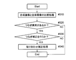
- FIG. 6 is a flowchart showing a control operation for crosstalk correction.
- a compound-eye optical system is an optical system in which a plurality of lens systems are arranged in an array with respect to an image sensor. Each lens system captures the same field of view, and each lens system captures a different field of view. It is usually divided into a visual field division type to perform.
- the compound eye optical system according to the present invention is a field division type that forms a plurality of images with different fields of view in order to connect a plurality of images with different fields of view and output a single composite image.
- the compound-eye optical system according to the present invention includes: a plurality of single-eye optical systems that form a plurality of images having different fields of view on an imaging surface of an imaging element (for example, a photoelectric conversion unit of a solid-state imaging element); A lens array plate (preferably at least 2) in which a plurality of lenses are integrally formed, and an overall optical system that forms an image of a visual field including a visual field obtained by a single-eye optical system on the imaging surface.
- the single-eye optical system and the entire optical system are configured by a single sheet.
- the imaging surface is preferably on one imaging element (that is, the same imaging element).
- the lens array plate is preferably composed of at least two. If there are at least two lenses, better optical performance can be secured.
- those other than the single-eye optical system having an optical axis perpendicular to the imaging surface capture images of different fields of view by decentering the lens surface vertex and the imaging surface center from each other. Or imaging of different fields of view by decentering the lens surface vertices.
- the composite image has a rectangular shape having a short side and a long side, and the entire optical system is arranged at a position shifted from the single-eye optical system in the short side direction.
- An imaging apparatus connects an imaging device, the compound eye optical system that forms a plurality of images with different fields of view to the imaging device, and a plurality of images with different fields of view formed by the compound eye optical system. And an image processing unit for outputting one composite image.
- a normal digital imaging device has a live view and movie shooting function in addition to a still image shooting function.
- power consumption reduction is important for reasons such as battery life and temperature rise. . If the temperature rise is large, the optical performance deteriorates due to the influence of deformation or refractive index change due to the temperature rise during movie shooting or live view. As a result, it is difficult to provide a photographing optical system and an imaging apparatus that always have good image quality.
- the cause of the heat generation that causes the temperature rise is the image output of the image sensor, the calculation of image pasting, and the like.
- An imaging apparatus that performs live view or video output using an entire optical system formed integrally with a single-eye optical system has not been known.
- a field division type imaging optical system having an entire optical system formed integrally with a single-eye optical system
- the burden of image output and image processing is reduced.
- another image pickup device is used for live view or moving image output, the size, processing circuit, mechanism, and the like are increased, which makes it difficult to reduce the size of the image pickup apparatus. Therefore, a configuration in which a single-eye image and a whole image are formed on the same image sensor is preferable.
- an integral array element that is, a lens array plate in which a plurality of lenses are integrally formed
- the arrangement of the entire optical system is a point.
- the lens is greatly decentered in the horizontal direction. Since the entire optical system is not decentered, an image pickup device space corresponding to the amount of decentering is created, and reducing this amount reduces the overall size of the compound-eye optical system.
- the entire optical system in the direction with the smaller amount of eccentricity (in other words, the direction with the smaller screen size: the position shifted in the short side direction).
- the image quality can be improved without increasing the thickness of the compound eye optical system. Therefore, it is possible to realize an ultra-thin and high-quality compound eye optical system and an ultra-thin and high-quality image pickup apparatus including the same.
- the compound eye optical system according to the present invention in a digital device such as a mobile phone or a portable information terminal, it becomes possible to add a high-performance image input function to the digital device in a compact manner. It can contribute to performance and high functionality. The conditions for achieving such effects in a well-balanced manner and achieving higher optical performance, downsizing, etc. will be described below.
- the image processing unit has a moving image output function, a live view output function, and a still image output function, and performs image processing for outputting the composite image at the time of still image output. It is preferable to perform output using image information of the entire optical system.
- the photographing is usually performed after confirming the photographing state on a liquid crystal display or an organic EL (Organic Electro-Luminescence) display screen of the mobile device. At that time, in order to display the composite image of the single-eye optical system on the display screen, it is necessary to perform the composite operation at high speed.
- the field of view of the entire optical system is larger than the entire field of view (synthetic field of view) obtained with a plurality of single-eye optical systems.
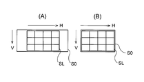
- 5A and 5B show examples of the positional relationship between the overall visual field S0 obtained by the overall optical system and the composite visual field SL obtained by the single-eye optical system (V: short side direction, H: long side). direction).
- Image information obtained by the entire optical system can be used for moving images and live views.
- the screen size of the moving image is 16: 9, and the screen size of the live view is the screen size of an image display device (for example, a liquid crystal display device) of a device (smart phone (high-function mobile phone) or the like) equipped with an imaging device.
- the screen is horizontally long (FIG. 5A). If the entire optical system cuts out an image of a partial area of the all-eye optical system, the entire still image area cannot be accommodated, which is not preferable as a live view. Accordingly, it is preferable to make the overall field of view S0 obtained by the overall optical system larger than the composite field of view SL obtained by a plurality of single-eye optical systems, and thereby, a composite image using image information obtained by the overall optical system. Image quality can be effectively improved.
- Conditional expression (1) defines a preferable condition for keeping the number of synthesized pixels high while having a necessary overlap.
- conditional expression (2) ⁇ 3 ⁇ F (whole, img) / F (unit, img) ⁇ 0 (2)
- F (unit, img) paraxial focal length of the lens on the most image side of the single-eye optical system having an optical axis perpendicular to the imaging surface
- F (hole, img) paraxial focal length of the lens closest to the image side of the entire optical system
- the whole optical system with a wide viewing angle and the single-eye optical system with a narrow viewing angle (long focal length) are designed with a normal configuration, the total length of the single-eye optical system becomes long. Therefore, design ingenuity is required to form the entire optical system and the single-eye optical system on the same substrate.
- conditional expression (2) If the upper limit of conditional expression (2) is exceeded, the total length of the single-eye optical system becomes too long, and the overall optical system becomes large, or formation on the same substrate becomes difficult. When the lower limit of conditional expression (2) is exceeded, the negative power of the single-eye optical system becomes too large, making it difficult to have good aberration performance.
- Conditional expression (3) defines another condition for placing the entire optical system on the same substrate. If the lower limit of conditional expression (3) is exceeded, the power on the object side becomes smaller than the power on the image side, so the merit of miniaturization, which is a feature of the telephoto type, becomes small. As a result, the overall length becomes large and it is difficult to reduce the thickness. If the upper limit of conditional expression (3) is exceeded, the power of each lens becomes too strong, making it difficult to correct aberrations and making it difficult to obtain good performance.
- those other than the single-eye optical system having an optical axis perpendicular to the imaging surface have a free-form surface.
- a decentered optical system having at least one surface is preferable. In order to reduce the thickness of the field division type compound-eye optical system, decentration is necessary (to eliminate the need for an optical path changing prism that causes an increase in thickness). However, in the decentered optical system, it is necessary to correct aberrations satisfactorily for obliquely incident light.
- the single-eye optical system having an eccentric surface preferably has a free-form surface, other than the single-eye optical system having an optical axis perpendicular to the imaging surface It is further preferable that all the decentered lenses have two or more free-form surfaces.
- An image formed by the single-eye optical system is a single-eye image
- an image formed by the whole optical system is a whole image
- an area where the single-eye image is formed on the imaging surface of the image sensor is a single-eye.
- the gap between the individual eye area and the entire area is larger than the gap between the individual eye areas.
- the eccentricity of the single-eye optical system changes in the order of arrangement, interference between the single-eye optical systems can be easily avoided, but it is difficult to avoid interference between the single-eye optical system and the entire optical system. is there. For this reason, it is preferable to make the gap (for example, 2 mm) between the individual eye area and the entire area larger than the gap (for example, 0.2 mm) for each area of the individual eye optical system.
- the gap for example, 2 mm
- the overall optical system is less affected by crosstalk than a single-eye optical system, and a very good image can be obtained. it can.
- the number of the individual optical systems is three or more in the vertical and horizontal directions, and each of the individual optical systems forms an image in a field of view shifted in the vertical and horizontal directions in an array of 3 ⁇ 3 or more.
- an arrangement of at least 3 ⁇ 3 is required.
- the compound eye optical system is suitable for reducing the thickness of the imaging device in both types, but the field division type performs imaging with a small field of view one by one. It is valid. However, in order to obtain a single composite image from a plurality of images with different fields of view, each image is inverted by the action of the lens and is reflected on the image sensor. Is required. In this case, when using an optical system that uses a lens array plate formed integrally and decenters each other to image different fields of view, there are the following problems (1) to (3). (1): Unnecessary light incident on a single eye reaches the adjacent sensor surface, and thus stray light ghosts due to crosstalk and inter-surface reflection occur.
- the compound-eye optical system according to the present invention forms a plurality of images having different fields of view with a plurality of single-eye optical systems on the imaging surface, and displays a field-of-view image including the fields of view obtained with the plurality of single-eye optical systems.
- the entire optical system is formed on the imaging surface.
- the image formed by the single-eye optical system and the image formed by the entire optical system can be formed on one image pickup device, it is possible to more effectively achieve downsizing of the entire image pickup apparatus.
- the image processing unit performs correction for improving the image quality of the composite image using image information obtained by the entire optical system.
- image information obtained by the entire optical system it is possible to improve the image quality of a composite image (single-eye composite image) restored from an image obtained by the single-eye optical system.
- the image information obtained by the entire optical system is crosstalk causing ghost
- the image processing unit specifies crosstalk generated in the composite image and corrects the ghost so that it is not noticeable.
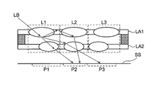
- Crosstalk means that light emitted from a specific optical system is incident on a sensor area different from the sensor area where it should be incident. For example, as shown in FIG. 6, among the lens systems L1 to L3 including the lens array plates LA1 and LA2, the light LB incident on the lens system L1 does not enter the sensor region P1 that should be incident on the imaging surface SS. The incident to the sensor regions P2 and P3 after entering the surrounding lens systems L2 and L3 is called crosstalk. Such crosstalk is likely to occur when an integrated lens array such as the lens array plates LA1 and LA2 is used.
- the control operation for crosstalk correction is shown in the flowchart of FIG.
- two steps of (1) a ghost identification process and (2) a ghost reduction process are executed.
- the ghost identification process the luminance values of the entire image and the synthesized image obtained from a plurality of single-eye images are compared, and a location where the luminance values have a large difference (location where crosstalk occurs) is identified (# 110). If it is determined that there is crosstalk (# 120) and it is determined that the crosstalk is at a level that requires correction (# 130), crosstalk reduction processing (ghost reduction processing) is performed (# 140). .
- this crosstalk reduction process a subtraction process is performed for the difference in luminance value from the composite image. As described above, by using the image information obtained by the entire optical system for the crosstalk reduction process, it is possible to perform an effective correction so that the ghost is not noticeable.
- Japanese Patent Application Laid-Open No. 2012-70443 The one described in Japanese Patent Application Laid-Open No. 2012-70443 is not a crosstalk correction of a compound eye optical system. However, when there is a high luminance portion in the screen, the occurrence of a ghost is predicted, and matching with an acquired image is performed to match the ghost. The presence or absence is specified, and the image quality is improved by subtraction processing. The principle of the ghost identification process and the subtraction process is the same concept as the crosstalk correction in the present invention, so that the crosstalk can be corrected by applying these processes. Further, as described in JP 2012-70443 A, a removal determination process may be inserted between the specifying process and the subtraction process.
- the image information obtained by the overall optical system is shading, and the image processing unit corrects the brightness distribution of the composite image using the brightness distribution information of the image of the overall optical system.
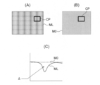
- FIG. 7A shows an example of the single-eye composite image ML
- FIG. 7B shows an example of the entire image M0.
- FIG. 7C shows a change in luminance ( ⁇ : luminance difference) in a region CP in FIGS. 7A and 7B.
- ⁇ luminance difference
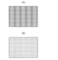
- FIG. 8 shows an example of a gray chart photographing result before (A) shading correction and after (B) shading correction.
- the shading correction control operation is shown in the flowchart of FIG.
- two steps are executed: (1) identification of shading presence and (2) shading reduction processing.
- the luminance values of the whole image and the single-eye composite image obtained from a plurality of single-eye images are compared, and a portion having a large difference in the luminance values (location where shading occurs) is specified ( # 210).
- # 210 a portion having a large difference in the luminance values (location where shading occurs) is specified.
- (A) single-eye composite image ML and (B) whole image M0 shown in FIG. 7 the cross section of the region CP (near the joint) and the luminance of the region CP are compared, and the luminance difference ⁇ is If it is above a certain amount, it can be determined that the shading abnormality is at a noticeable level.
- shading reduction processing is performed (# 240).
- this shading reduction process since the luminance distribution of the entire image M0 is close to the original luminance, the luminance of the single-eye synthesized image ML is changed so as to eliminate the luminance difference ⁇ . At that time, it is desirable to be able to adjust the level to be corrected.
- image information obtained by the entire optical system is a joint of the composite image
- the image processing unit corrects the joint distribution of the composite image using the image information of the entire optical system.
- FIG. 9A shows a composite image before connection correction
- FIG. 9B shows a composite image after connection correction.
- FIG. 10 shows the influence of parallax due to the difference in subject distance on stitching.
- FIG. 10A shows a state in which the short-distance object NB and the reference distance object FB are photographed by the imaging device DU.
- FIG. 10B shows the entire image M0, and FIG. Indicates a single-eye composite image ML.
- Fig. 13 is a flowchart showing the connection correction control operation.
- connection correction two steps of (1) a connection abnormality specifying process and (2) a bonding correction process are executed.
- the joint abnormality identification process the luminance values of the entire image and the composite image obtained from a plurality of single-eye images are compared, and a portion having a large difference in the luminance values (location where the joint abnormality occurs) is identified ( # 310). If it is determined that there is a joining abnormality (# 320), and it is judged that the joining abnormality is at a level that requires correction (# 330), a bonding correction process (a joining abnormality reducing process) is performed (# 340). .
- a joining abnormality reducing process is performed (# 340).
- FIG. 1 shows the first embodiment of the imaging apparatus
- FIG. 2 shows the first embodiment of the compound-eye optical system
- FIG. 3 shows the positions of the compound-eye optical system and the imaging region in the first embodiment. Show the relationship.
- the imaging device DU includes an imaging unit LU, an image processing unit 1, a calculation unit 2, a memory 3, and the like.
- the imaging unit LU includes one imaging element SR and a compound-eye optical system LH that performs a plurality of imaging with different fields of view on the imaging element SR.
- the image sensor SR for example, a solid-state image sensor such as a CCD image sensor or a CMOS image sensor having a plurality of pixels is used.
- the compound eye optical system LH is provided on the light receiving surface SS which is a photoelectric conversion unit of the image sensor SR so that an optical image of the subject is formed, the optical image formed by the compound eye optical system LH is captured. It is converted into an electrical signal by the element SR.
- the plurality of single-eye optical systems Ln And have.
- the single-eye optical system Ln and the entire optical system L0 are each composed of two lenses, an object-side lens and an image-side lens, and a first lens array plate LA1 in which a plurality of object-side lenses are integrally formed, and a plurality of lenses And a second lens array plate LA2 on which the image side lens is integrally formed.
- a cover glass CG of the imaging element SR is disposed on the image side of the second lens array plate LA2 as shown in FIG.
- An entire region P0 (P01 to P03) where the entire image Z0 is formed at L0 is shown as an imaging region.
- FIG. 3B a part (L13 to L15, L18 to L20, and L18) of a single-eye optical system Ln that forms a single-eye image Zn (FIGS. 1 and 2) in the single-eye region Pn (FIG. 3A). L23 to L25) and the entire optical system L0 (L01 to L03) for forming the entire image Z0 (FIGS.
- FIG. 3B shows a state in which the single-eye optical system Ln and the entire optical system L0 are viewed from above (for example, an elliptical shape is a decentered state of the lens system).
- 2 corresponds to a cross-sectional view taken along the line QQ ′ of FIG. 3B (one cross section in the V direction), but the single-eye optical system Ln has a vertically and laterally symmetrical arrangement, so FIG. ) Shows only the single-eye optical system Ln in 9 positions (L13 to L15, L18 to L20, L23 to L25).
- the single-eye optical system Ln and the single-eye region Pn have a corresponding arrangement of 5 ⁇ 5. Yes.
- the central single-eye optical system L13 forms an image of the subject central portion
- the peripheral single-eye optical system Ln (other than L13) forms an image of the subject peripheral portion.
- the angle of view of any single-eye optical system Ln is narrow.
- the single-eye optical system Ln has a two-lens configuration, and the central single-eye optical system L13 (optical axis AX perpendicular to the imaging surface SS) shown in FIG.
- the power arrangement is a positive / negative telephoto type.
- all four lens surfaces are free-form surfaces. With the configuration having four free-form surfaces, very good aberration performance can be realized.
- the optical axis AX is decentered in order to form the peripheral visual field, so that it is not necessary to use an optical path changing prism or the like.
- the thickness of all the single-eye optical systems Ln can be made the same, and the design on the same substrate becomes possible. Since the single-eye optical system Ln constituting the peripheral visual field makes light incident obliquely with respect to the imaging surface SS, it is preferable to have four free-form surfaces in order to obtain the same optical performance as the axially symmetric optical system.
- each of the three total optical systems L01 to L03 is a lens system (having an optical axis AX perpendicular to the imaging surface SS) that forms an image of the entire subject, and includes one single-eye optical system Ln. It has 5 times the angle of view.
- the compound eye optical system LH may include one or a plurality of total optical systems L0. If an attempt is made to arrange the entire optical system L0 together with the single-eye optical system Ln, there is a margin in space, and therefore it is possible to arrange a plurality of entire optical systems L0. For example, if a plurality of whole optical systems L0 are used, a plurality of images obtained thereby can be used for output of distance information and 3D images.
- the image processing unit 1 includes an image composition unit 1a, an image correction unit 1b, and an output image processing unit 1c.
- the image quality of the single-eye composite image ML to be restored is improved. That is, as described above, the image correction unit 1b specifies the crosstalk generated in the single-eye composite image ML and corrects the ghost so that it is not conspicuous, or the luminance distribution information of the entire image M0 of the entire optical system L0.
- the luminance distribution of the single-eye composite image ML is used for shading correction, or the joint distribution of the single-eye composite image ML is corrected using the image information M0 of the entire optical system L0. Further, distortion correction is performed as necessary.
- the output image processing unit 1c performs resolution conversion and image quality improvement using the entire image Z0 and outputs the entire image M0. Since the image processing unit 1 has a moving image output function, a live view output function, and a still image output function, the image processing unit 1 performs image processing for outputting the single-eye composite image ML when outputting a still image. At the time of live view output, the output image processing unit 1c performs output using image information of the entire optical system Ln.
- FIG. 4 shows the positional relationship between the compound eye optical system and the imaging region in the second embodiment so as to correspond to FIG. Since the second embodiment is configured to perform 4 ⁇ 3 field division, as can be seen from FIG. 4, the single-eye optical system Ln and the single-eye region Pn are arranged in a corresponding arrangement of 4 ⁇ 3. Yes. Since the single-eye optical system Ln does not exist at the center of all the single-eye regions Pn, all the single-eye optical systems Ln are decentered optical systems. Below the single-eye optical system Ln, two lens systems L01 and L02 having the same configuration as the entire optical system L0 are arranged.
- Each of the two whole optical systems L01 and L02 is a lens system (having an optical axis AX perpendicular to the imaging surface SS) that forms an image of the entire subject, and is composed of one single-eye optical system Ln. It has a field angle more than 4 times.
- the size of each region for example, if the number of pixels on the imaging surface SS is 16M pixels, 12M pixels can be used for the entire single eye region Pn, and the remaining 2M pixels can be used for each entire region P0.
- the entire optical systems L01 and L02 different parallax information can be obtained at the same angle of view, so that 3D image output, distance image output, and super-resolution image output may be performed. In this embodiment, since there are 2M pixels, it is also possible to output a 3D moving image with high-definition image quality.
- the configuration of the compound eye optical system embodying the present invention will be described more specifically with reference to construction data.
- the examples given here are numerical examples corresponding to the above-described first embodiment, and the optical configuration diagram (FIG. 2) representing the first embodiment of the compound-eye optical system LH is a corresponding numerical example.
- An example lens configuration, optical path, etc. are shown.
- Table 1 shows the area arrangement of the single-eye optical system Ln and the entire optical system L0 in this example.
- the single-eye optical system Ln is arranged at 5 ⁇ 5 positions, and the entire optical system L0 is arranged at three positions.
- the single-eye optical system Ln has a vertically and horizontally symmetrical arrangement, only 9 positions (C, V1, V2, H1, H2, D1, D2, VD, and HD) are shown.
- the surface number and curvature C0 are sequentially displayed as surface data from the left column.
- the reciprocal of radius, 1 / mm), the axial distance d (mm), the refractive index nd for the d-line (wavelength: 587.56 nm), and the Abbe number vd for the d-line are shown.
- C0 the reciprocal of the radius of curvature, 1 / mm
- d the shaft upper surface distance
- Y eccentricity the Y eccentricity
- “90 degree rotation” of the single-eye optical system Ln means that a surface is created according to the construction data and rotated 90 degrees around the Z axis to become the lens state. . Therefore, the eccentric direction and the free-form surface coefficient are the same as when X and Y are interchanged (the H direction corresponds to the X direction and the V direction corresponds to the Y direction).
- an aspheric surface that is rotationally symmetric about the optical axis AX is used. It is defined by the following expression (AS) using a local orthogonal coordinate system (X, Y, Z) with the surface vertex as the origin.
- a free-form surface is used for the single-eye optical system Ln (position: V1, VD, D1, V2, D2, HD, H2, H1) that is a decentered optical system, and the free-form surface has its surface vertex as the origin.
- the aspheric coefficient is shown as aspheric data
- the free-form surface coefficient is shown as free-form surface data (where A (j, k) is expressed as X j ⁇ Y k ).
- V2 Unit mm Surface data Surface number C0 d Y Eccentric 1 1.0937088 0.228 0.000 2 0 0.305 0.011 3 0 0.065 0.011 4 1.2847229 0.764 0.022 5 0.5588239 0.119 0.210 6 0 0.300 0.210 7 0 0.050 0.210 8 -2.429775 0.150 0.338 9 0 0.500 0.445 10 0 0.050 0.445
- Position H1 (90 degree rotation) Unit: mm Surface data Surface number C0 d Y Eccentric 1 1.0256853 0.132 0.000 2 0 0.305 0.034 3 0 0.050 0.034 4 1.1274901 0.849 0.058 5 1.1551341 0.051 0.660 6 0 0.300 0.660 7 0 0.075 0.660 8 -2.401183 0.124 0.917 9 0 0.500 1.177 10 0 0.050 1.177
- Position H2 (90 degree rotation) Unit: mm Surface data Surface number C0 d Y Eccentric 1 0.8961863 0.246 0.000 2 0 0.305 0.018 3 0 0.050 0.018 4 1.2800572 0.789 0.033 5 1.204035 0.111 0.376 6 0 0.300 0.376 7 0 0.055 0.376 8 -2.297383 0.145 0.526 9 0 0.500 0.651 10 0 0.050 0.651
- Position HD (90 degree rotation) Unit: mm Surface data Surface number C0 d Y Eccentric X Eccentric 1 1.0415235 0.126 0.000 0.000 2 0 0.305 0.070 0.026 3 0 0.050 0.070 0.026 4 2.7137362 0.824 0.131 0.058 5 1.8378488 0.076 0.637 0.250 6 0 0.300 0.637 0.250 7 0 0.077 0.637 0.250 8 -2.419797 0.122 0.937 0.321 9 0 0.500 1.224 0.449 10 0 0.050 1.224 0.449
- Position D2 (90 degree rotation) Unit: mm Surface data Surface number C0 d Y Eccentric X Eccentric 1 -0.047356 0.153 0.000 0.000 2 0 0.305 0.029 0.024 3 0 0.050 0.029 0.024 4 2.8552766 0.843 0.058 0.050 5 2.3216459 0.058 0.353 0.265 6 0 0.300 0.353 0.265 7 0 0.053 0.353 0.265 8 -2.430046 0.147 0.452 0.313 9 0 0.500 0.603 0.398 10 0 0.050 0.603 0.398
- Aspheric coefficient 8th surface A4 1.401E + 00
- A6 1.055E + 01
- A8 -3.211E + 02
- A10 3.237E + 03
- A12 -1.658E + 04
Abstract
L'invention concerne un système optique composé qui, de façon à relier une pluralité d'images ayant différents champs visuels et à délivrer une image composite, forme une pluralité d'images ayant différents champs visuels. Le système optique composé comprend : une pluralité de systèmes optiques à lentille individuelle dans lesquels une pluralité d'images ayant différents champs visuels sont formées sur une surface d'imagerie ; et un système optique global formant, sur la surface d'imagerie, une image ayant un champ visuel englobant les champs visuels obtenus par la pluralité de systèmes optiques à lentille individuelle. Les systèmes optiques à lentille individuelle et le système optique global sont configurés par une plaque de réseau de lentilles comprenant une pluralité de lentilles formées d'un seul tenant dans celle-ci. Les systèmes optiques à lentille individuelle, parmi la pluralité de systèmes optiques à lentille individuelle, ne comprenant pas d'axe optique vertical par rapport à la surface d'imagerie réalisent une imagerie ayant différents champs visuels, par le sommet de la surface de lentille et le centre de la surface d'imagerie qui sont mutuellement excentriques ; l'image composite comprend une forme rectangulaire ayant des côtés courts et des côtés longs ; et le système optique global est agencé à une position déplacée par rapport aux systèmes optiques à lentille individuelle dans la direction côté court.
Priority Applications (1)
| Application Number | Priority Date | Filing Date | Title |
|---|---|---|---|
| JP2014552004A JPWO2014091986A1 (ja) | 2012-12-11 | 2013-12-04 | 複眼光学系とそれを用いた撮像装置 |
Applications Claiming Priority (2)
| Application Number | Priority Date | Filing Date | Title |
|---|---|---|---|
| JP2012-270686 | 2012-12-11 | ||
| JP2012270686 | 2012-12-11 |
Publications (1)
| Publication Number | Publication Date |
|---|---|
| WO2014091986A1 true WO2014091986A1 (fr) | 2014-06-19 |
Family
ID=50934278
Family Applications (1)
| Application Number | Title | Priority Date | Filing Date |
|---|---|---|---|
| PCT/JP2013/082587 WO2014091986A1 (fr) | 2012-12-11 | 2013-12-04 | Système optique composé et dispositif d'imagerie utilisant celui-ci |
Country Status (2)
| Country | Link |
|---|---|
| JP (1) | JPWO2014091986A1 (fr) |
| WO (1) | WO2014091986A1 (fr) |
Cited By (1)
| Publication number | Priority date | Publication date | Assignee | Title |
|---|---|---|---|---|
| JP2021103181A (ja) * | 2017-04-13 | 2021-07-15 | フラウンホーファー−ゲゼルシャフト・ツール・フェルデルング・デル・アンゲヴァンテン・フォルシュング・アインゲトラーゲネル・フェライン | 部分視野を撮像するための装置、多開口撮像装置およびそれらを提供する方法 |
Citations (5)
| Publication number | Priority date | Publication date | Assignee | Title |
|---|---|---|---|---|
| JP2006171939A (ja) * | 2004-12-14 | 2006-06-29 | Canon Inc | 画像処理装置及び方法 |
| WO2006101064A1 (fr) * | 2005-03-24 | 2006-09-28 | Matsushita Electric Industrial Co., Ltd. | Dispositif d’imagerie et arrangement de lentilles utilisé dedans |
| JP2010130628A (ja) * | 2008-12-01 | 2010-06-10 | Sharp Corp | 撮像装置、映像合成装置および映像合成方法 |
| JP2010147695A (ja) * | 2008-12-17 | 2010-07-01 | Nikon Corp | 撮像装置 |
| JP2013045032A (ja) * | 2011-08-26 | 2013-03-04 | Fujifilm Corp | 多眼撮像装置 |
-
2013
- 2013-12-04 WO PCT/JP2013/082587 patent/WO2014091986A1/fr active Application Filing
- 2013-12-04 JP JP2014552004A patent/JPWO2014091986A1/ja active Pending
Patent Citations (5)
| Publication number | Priority date | Publication date | Assignee | Title |
|---|---|---|---|---|
| JP2006171939A (ja) * | 2004-12-14 | 2006-06-29 | Canon Inc | 画像処理装置及び方法 |
| WO2006101064A1 (fr) * | 2005-03-24 | 2006-09-28 | Matsushita Electric Industrial Co., Ltd. | Dispositif d’imagerie et arrangement de lentilles utilisé dedans |
| JP2010130628A (ja) * | 2008-12-01 | 2010-06-10 | Sharp Corp | 撮像装置、映像合成装置および映像合成方法 |
| JP2010147695A (ja) * | 2008-12-17 | 2010-07-01 | Nikon Corp | 撮像装置 |
| JP2013045032A (ja) * | 2011-08-26 | 2013-03-04 | Fujifilm Corp | 多眼撮像装置 |
Cited By (3)
| Publication number | Priority date | Publication date | Assignee | Title |
|---|---|---|---|---|
| JP2021103181A (ja) * | 2017-04-13 | 2021-07-15 | フラウンホーファー−ゲゼルシャフト・ツール・フェルデルング・デル・アンゲヴァンテン・フォルシュング・アインゲトラーゲネル・フェライン | 部分視野を撮像するための装置、多開口撮像装置およびそれらを提供する方法 |
| US11457152B2 (en) | 2017-04-13 | 2022-09-27 | Fraunhofer-Gesellschaft zur Förderung der angewandten Forschung e.V. | Device for imaging partial fields of view, multi-aperture imaging device and method of providing same |
| JP7189992B2 (ja) | 2017-04-13 | 2022-12-14 | フラウンホーファー-ゲゼルシャフト・ツール・フェルデルング・デル・アンゲヴァンテン・フォルシュング・アインゲトラーゲネル・フェライン | 部分視野を撮像するための装置、多開口撮像装置およびそれらを提供する方法 |
Also Published As
| Publication number | Publication date |
|---|---|
| JPWO2014091986A1 (ja) | 2017-01-12 |
Similar Documents
| Publication | Publication Date | Title |
|---|---|---|
| JP6172161B2 (ja) | 複眼光学系とそれを用いた撮像装置 | |
| US11796772B2 (en) | Imaging lens | |
| US20210278638A1 (en) | Imaging lens | |
| US20190310446A1 (en) | Imaging lens | |
| US9091836B2 (en) | Lens module | |
| US7593165B2 (en) | Zoom lens and image sensing apparatus | |
| US7593164B2 (en) | Zoom lens system and image-sensing apparatus having image shake correcting capability | |
| US9239514B2 (en) | Imaging apparatus and electronic device for producing stereoscopic images | |
| US9417432B2 (en) | Imaging lens | |
| JP2006349920A (ja) | 撮影光学系、撮影レンズユニット、カメラおよび携帯情報端末装置 | |
| JP2013106289A (ja) | 撮像装置 | |
| US20220206254A1 (en) | Optical system, camera module, and electronic apparatus | |
| TWI779949B (zh) | 成像透鏡系統 | |
| WO2014091986A1 (fr) | Système optique composé et dispositif d'imagerie utilisant celui-ci | |
| US20230103427A1 (en) | Optical system, image acquisition module and electronic device | |
| US20220299736A1 (en) | Optical system, lens module, and terminal device |
Legal Events
| Date | Code | Title | Description |
|---|---|---|---|
| 121 | Ep: the epo has been informed by wipo that ep was designated in this application |
Ref document number: 13861643 Country of ref document: EP Kind code of ref document: A1 |
|
| ENP | Entry into the national phase |
Ref document number: 2014552004 Country of ref document: JP Kind code of ref document: A |
|
| NENP | Non-entry into the national phase |
Ref country code: DE |
|
| 122 | Ep: pct application non-entry in european phase |
Ref document number: 13861643 Country of ref document: EP Kind code of ref document: A1 |