WO2014091986A1 - Compound optical system and imaging device using same - Google Patents
Compound optical system and imaging device using same Download PDFInfo
- Publication number
- WO2014091986A1 WO2014091986A1 PCT/JP2013/082587 JP2013082587W WO2014091986A1 WO 2014091986 A1 WO2014091986 A1 WO 2014091986A1 JP 2013082587 W JP2013082587 W JP 2013082587W WO 2014091986 A1 WO2014091986 A1 WO 2014091986A1
- Authority
- WO
- WIPO (PCT)
- Prior art keywords
- optical system
- image
- eye
- eye optical
- view
- Prior art date
Links
- 230000003287 optical effect Effects 0.000 title claims abstract description 381
- 238000003384 imaging method Methods 0.000 title claims abstract description 138
- 150000001875 compounds Chemical class 0.000 title claims abstract description 39
- 239000002131 composite material Substances 0.000 claims abstract description 60
- 238000012545 processing Methods 0.000 claims description 48
- 238000012937 correction Methods 0.000 claims description 27
- 238000009826 distribution Methods 0.000 claims description 14
- 230000000007 visual effect Effects 0.000 abstract description 17
- 238000000034 method Methods 0.000 description 21
- 230000008569 process Effects 0.000 description 19
- 230000006870 function Effects 0.000 description 11
- 230000005856 abnormality Effects 0.000 description 8
- 238000003705 background correction Methods 0.000 description 8
- 238000005304 joining Methods 0.000 description 8
- 239000000758 substrate Substances 0.000 description 6
- 230000004075 alteration Effects 0.000 description 5
- 238000004364 calculation method Methods 0.000 description 5
- 230000009467 reduction Effects 0.000 description 5
- 238000010276 construction Methods 0.000 description 4
- 238000013461 design Methods 0.000 description 4
- 238000003702 image correction Methods 0.000 description 4
- 230000002093 peripheral effect Effects 0.000 description 4
- 238000011946 reduction process Methods 0.000 description 4
- 230000008859 change Effects 0.000 description 3
- 238000006243 chemical reaction Methods 0.000 description 3
- 239000013256 coordination polymer Substances 0.000 description 3
- 238000010586 diagram Methods 0.000 description 3
- 239000006059 cover glass Substances 0.000 description 2
- 230000020169 heat generation Effects 0.000 description 2
- 238000012905 input function Methods 0.000 description 2
- 239000004973 liquid crystal related substance Substances 0.000 description 2
- 239000000203 mixture Substances 0.000 description 2
- 230000009471 action Effects 0.000 description 1
- 230000015572 biosynthetic process Effects 0.000 description 1
- 230000000295 complement effect Effects 0.000 description 1
- 230000007547 defect Effects 0.000 description 1
- 238000006073 displacement reaction Methods 0.000 description 1
- 230000000694 effects Effects 0.000 description 1
- 238000005401 electroluminescence Methods 0.000 description 1
- 230000006872 improvement Effects 0.000 description 1
- 238000004519 manufacturing process Methods 0.000 description 1
- 230000007246 mechanism Effects 0.000 description 1
- 229910044991 metal oxide Inorganic materials 0.000 description 1
- 150000004706 metal oxides Chemical class 0.000 description 1
- 230000004044 response Effects 0.000 description 1
- 239000004065 semiconductor Substances 0.000 description 1
- 230000035945 sensitivity Effects 0.000 description 1
- 238000004904 shortening Methods 0.000 description 1
- 230000002194 synthesizing effect Effects 0.000 description 1
Images
Classifications
-
- G—PHYSICS
- G03—PHOTOGRAPHY; CINEMATOGRAPHY; ANALOGOUS TECHNIQUES USING WAVES OTHER THAN OPTICAL WAVES; ELECTROGRAPHY; HOLOGRAPHY
- G03B—APPARATUS OR ARRANGEMENTS FOR TAKING PHOTOGRAPHS OR FOR PROJECTING OR VIEWING THEM; APPARATUS OR ARRANGEMENTS EMPLOYING ANALOGOUS TECHNIQUES USING WAVES OTHER THAN OPTICAL WAVES; ACCESSORIES THEREFOR
- G03B15/00—Special procedures for taking photographs; Apparatus therefor
-
- G—PHYSICS
- G03—PHOTOGRAPHY; CINEMATOGRAPHY; ANALOGOUS TECHNIQUES USING WAVES OTHER THAN OPTICAL WAVES; ELECTROGRAPHY; HOLOGRAPHY
- G03B—APPARATUS OR ARRANGEMENTS FOR TAKING PHOTOGRAPHS OR FOR PROJECTING OR VIEWING THEM; APPARATUS OR ARRANGEMENTS EMPLOYING ANALOGOUS TECHNIQUES USING WAVES OTHER THAN OPTICAL WAVES; ACCESSORIES THEREFOR
- G03B35/00—Stereoscopic photography
- G03B35/08—Stereoscopic photography by simultaneous recording
-
- H—ELECTRICITY
- H01—ELECTRIC ELEMENTS
- H01L—SEMICONDUCTOR DEVICES NOT COVERED BY CLASS H10
- H01L27/00—Devices consisting of a plurality of semiconductor or other solid-state components formed in or on a common substrate
- H01L27/14—Devices consisting of a plurality of semiconductor or other solid-state components formed in or on a common substrate including semiconductor components sensitive to infrared radiation, light, electromagnetic radiation of shorter wavelength or corpuscular radiation and specially adapted either for the conversion of the energy of such radiation into electrical energy or for the control of electrical energy by such radiation
- H01L27/144—Devices controlled by radiation
- H01L27/146—Imager structures
- H01L27/14601—Structural or functional details thereof
- H01L27/14625—Optical elements or arrangements associated with the device
- H01L27/14627—Microlenses
-
- H—ELECTRICITY
- H01—ELECTRIC ELEMENTS
- H01L—SEMICONDUCTOR DEVICES NOT COVERED BY CLASS H10
- H01L27/00—Devices consisting of a plurality of semiconductor or other solid-state components formed in or on a common substrate
- H01L27/14—Devices consisting of a plurality of semiconductor or other solid-state components formed in or on a common substrate including semiconductor components sensitive to infrared radiation, light, electromagnetic radiation of shorter wavelength or corpuscular radiation and specially adapted either for the conversion of the energy of such radiation into electrical energy or for the control of electrical energy by such radiation
- H01L27/144—Devices controlled by radiation
- H01L27/146—Imager structures
- H01L27/14601—Structural or functional details thereof
- H01L27/14625—Optical elements or arrangements associated with the device
- H01L27/14629—Reflectors
-
- H—ELECTRICITY
- H04—ELECTRIC COMMUNICATION TECHNIQUE
- H04N—PICTORIAL COMMUNICATION, e.g. TELEVISION
- H04N23/00—Cameras or camera modules comprising electronic image sensors; Control thereof
- H04N23/60—Control of cameras or camera modules
- H04N23/667—Camera operation mode switching, e.g. between still and video, sport and normal or high- and low-resolution modes
-
- H—ELECTRICITY
- H04—ELECTRIC COMMUNICATION TECHNIQUE
- H04N—PICTORIAL COMMUNICATION, e.g. TELEVISION
- H04N25/00—Circuitry of solid-state image sensors [SSIS]; Control thereof
- H04N25/60—Noise processing, e.g. detecting, correcting, reducing or removing noise
- H04N25/62—Detection or reduction of noise due to excess charges produced by the exposure, e.g. smear, blooming, ghost image, crosstalk or leakage between pixels
-
- G—PHYSICS
- G03—PHOTOGRAPHY; CINEMATOGRAPHY; ANALOGOUS TECHNIQUES USING WAVES OTHER THAN OPTICAL WAVES; ELECTROGRAPHY; HOLOGRAPHY
- G03B—APPARATUS OR ARRANGEMENTS FOR TAKING PHOTOGRAPHS OR FOR PROJECTING OR VIEWING THEM; APPARATUS OR ARRANGEMENTS EMPLOYING ANALOGOUS TECHNIQUES USING WAVES OTHER THAN OPTICAL WAVES; ACCESSORIES THEREFOR
- G03B19/00—Cameras
- G03B19/02—Still-picture cameras
- G03B19/04—Roll-film cameras
- G03B19/07—Roll-film cameras having more than one objective
Landscapes
- Physics & Mathematics (AREA)
- Engineering & Computer Science (AREA)
- General Physics & Mathematics (AREA)
- Power Engineering (AREA)
- Electromagnetism (AREA)
- Condensed Matter Physics & Semiconductors (AREA)
- Computer Hardware Design (AREA)
- Microelectronics & Electronic Packaging (AREA)
- Multimedia (AREA)
- Signal Processing (AREA)
- Studio Devices (AREA)
- Cameras In General (AREA)
Abstract
A compound optical system that, in order to connect a plurality of images having different visual fields and output one composite image, forms a plurality of images having different visual fields. The compound optical system has: a plurality of individual-lens optical systems in which a plurality of images having different visual fields are formed upon an imaging surface; and an overall optical system forming, upon the imaging surface, an image having a visual field encompassing the visual fields obtained by the plurality of individual-lens optical systems. The individual-lens optical systems and the overall optical system are configured by a lens array plate having a plurality of lenses integrally formed therein. The individual-lens optical systems, among the plurality of individual-lens optical systems, that do not have a vertical optical axis relative to the imaging surface perform imaging having different visual fields, by the apex of the lens surface and the center of the imaging surface being mutually eccentric; the composite image comprises a rectangular shape having short sides and long sides; and the overall optical system is arranged at a position displaced from the individual-lens optical systems in the short-side direction.
Description
本発明は、複眼光学系とそれを用いた撮像装置に関するものであり、例えば、アレイレンズからなる視野分割タイプの複眼光学系と、それにより得られた被写体像を撮像素子(例えば、CCD(Charge Coupled Device)型イメージセンサー,CMOS(Complementary Metal-Oxide Semiconductor)型イメージセンサー等の固体撮像素子)で取り込む撮像装置と、に関するものである。
The present invention relates to a compound-eye optical system and an imaging apparatus using the compound-eye optical system. For example, a field-divided compound-eye optical system composed of an array lens and a subject image obtained thereby are captured by an image sensor (for example, a CCD (Charge The present invention relates to an imaging device that captures with a coupled device (Image sensor), a solid-state imaging device such as a CMOS (Complementary Metal-Oxide Semiconductor) image sensor).
近年の撮像光学系に対する薄型化の要求は非常に大きい。それに対応するために、光学設計による全長短縮やそれに伴う誤差感度増大に対応した製造精度向上を行ってきたが、さらなる要求に対応するためには、従来の1つの光学系と撮像素子とで像を得るということでは不十分になっている。そこで、薄型化への要求に対応するために、複眼光学系と呼ばれる撮像光学系が注目されている。複眼光学系はアレイ状に配置された複数のレンズからなるアレイ光学系であり、撮像素子において複数に分割された撮像領域に対して、それぞれが結像を行うものである。得られた複数の画像は、最終的に1つの画像となるように処理されて出力される。
Demand for thinner imaging optical systems in recent years is very large. In order to respond to this, we have improved the manufacturing accuracy in response to the shortening of the overall length by optical design and the accompanying increase in error sensitivity, but in order to respond to further demands, an image is obtained with one conventional optical system and an image sensor. It is not enough to get. Therefore, in order to meet the demand for thinning, an imaging optical system called a compound eye optical system has attracted attention. The compound eye optical system is an array optical system composed of a plurality of lenses arranged in an array, and each forms an image on an imaging region divided into a plurality of parts in the imaging device. The obtained plurality of images are processed and output so as to finally become one image.
各種の複眼光学系が特許文献1~3や非特許文献1で提案されている。例えば、特許文献1に記載の複眼光学系は、同じ視野の撮像を行う複数のアレイ光学系からなり、そのわずかな視差のズレを用いて超解像処理を行うためのものである。非特許文献1に記載の複眼光学系は、1枚のアレイ光学系の偏心で視野分割を行うものであり、特許文献2,3に記載の複眼光学系は、光路変更用のプリズムで視野分割を行うものである。
Various compound eye optical systems have been proposed in Patent Documents 1 to 3 and Non-Patent Document 1. For example, the compound eye optical system described in Patent Document 1 is composed of a plurality of array optical systems that capture an image of the same field of view, and performs super-resolution processing using a slight parallax shift. The compound eye optical system described in Non-Patent Document 1 performs field division by the eccentricity of one array optical system, and the compound eye optical system described in Patent Documents 2 and 3 uses a prism for changing an optical path. Is to do.
上記特許文献1に記載の複眼光学系を用いて行われる超解像処理には、複雑な画像処理が必要であるため、計算時間が非常にかかることから連写等が困難であり、更に出力画像の画質が良くない等の問題がある。一方、非特許文献1に記載の複眼光学系では高画素化が難しく、特許文献2,3に記載の複眼光学系ではプリズムがあるため薄型化が難しい。したがって、従来より知られている複眼光学系には、いずれのタイプも超薄型化と高画質化を同時に達成することができないという問題がある。
The super-resolution processing performed using the compound-eye optical system described in Patent Document 1 requires complicated image processing, so that it takes a lot of calculation time, so that continuous shooting or the like is difficult, and output is further performed. There are problems such as poor image quality. On the other hand, in the compound eye optical system described in Non-Patent Document 1, it is difficult to increase the number of pixels, and in the compound eye optical systems described in Patent Documents 2 and 3, it is difficult to reduce the thickness because there is a prism. Therefore, conventionally known compound eye optical systems have a problem that none of them can achieve ultra-thinness and high image quality at the same time.
本発明はこのような問題点に鑑みてなされたものであって、その目的は、超薄型で高画質の複眼光学系とそれを用いた撮像装置を提供することにある。
The present invention has been made in view of such problems, and an object thereof is to provide an ultra-thin, high-quality compound-eye optical system and an imaging apparatus using the same.
上記目的を達成するために、第1の発明の複眼光学系は、視野の異なる複数の像をつなぎ合わせて1枚の合成画像を出力するために、視野の異なる複数の結像を行う複眼光学系であって、
前記視野の異なる複数の像を撮像面上に形成する複数の個眼光学系と、前記複数の個眼光学系で得られる視野を包含する視野の像を前記撮像面上に形成する全体光学系と、を有しており、
複数のレンズが一体に形成されたレンズアレイプレートで、前記個眼光学系及び全体光学系が構成されており、
前記複数の個眼光学系のうち、前記撮像面に対して垂直な光軸を有する個眼光学系以外のものは、レンズ面頂点と撮像面中心とが互いに偏心することで異なる視野の撮像を行い、
前記合成画像が短辺と長辺を有する長方形をなしており、前記個眼光学系から前記短辺方向にずれた位置に前記全体光学系が配置されていることを特徴とする。 To achieve the above object, the compound-eye optical system of the first invention is a compound-eye optical system that forms a plurality of images with different fields of view in order to connect a plurality of images with different fields of view and output a single composite image. A system,
A plurality of single-eye optical systems that form a plurality of images with different fields of view on an imaging surface, and an overall optical system that forms a field-of-view image including the fields of view obtained by the plurality of single-eye optical systems on the imaging surface And
In the lens array plate in which a plurality of lenses are integrally formed, the single-eye optical system and the entire optical system are configured,
Among the plurality of single-eye optical systems, those other than the single-eye optical system having an optical axis perpendicular to the imaging surface capture images of different fields of view by decentering the lens surface vertex and the imaging surface center from each other. Done
The composite image has a rectangular shape having a short side and a long side, and the entire optical system is arranged at a position shifted from the single-eye optical system in the short side direction.
第2の発明の複眼光学系は、視野の異なる複数の像をつなぎ合わせて1枚の合成画像を出力するために、視野の異なる複数の結像を行う複眼光学系であって、
前記視野の異なる複数の像を撮像面上に形成する複数の個眼光学系と、前記複数の個眼光学系で得られる視野を包含する視野の像を前記撮像面上に形成する全体光学系と、を有しており、
複数のレンズが一体に形成された少なくとも2枚のレンズアレイプレートで、前記個眼光学系及び全体光学系が構成されており、
前記複数の個眼光学系のうち、前記撮像面に対して垂直な光軸を有する個眼光学系以外のものは、レンズ面頂点が互いに偏心することで異なる視野の撮像を行い、
前記合成画像が短辺と長辺を有する長方形をなしており、前記個眼光学系から前記短辺方向にずれた位置に前記全体光学系が配置されていることを特徴とする。 The compound eye optical system of the second invention is a compound eye optical system that forms a plurality of images with different fields of view in order to output a single composite image by joining a plurality of images with different fields of view.
A plurality of single-eye optical systems that form a plurality of images with different fields of view on an imaging surface, and an overall optical system that forms a field-of-view image including the fields of view obtained by the plurality of single-eye optical systems on the imaging surface And
The single-eye optical system and the entire optical system are configured with at least two lens array plates in which a plurality of lenses are integrally formed,
Among the plurality of single-eye optical systems, those other than the single-eye optical system having an optical axis perpendicular to the imaging surface perform imaging of different fields of view by decentering the lens surface vertices,
The composite image has a rectangular shape having a short side and a long side, and the entire optical system is arranged at a position shifted from the single-eye optical system in the short side direction.
第3の発明の複眼光学系は、上記第1又は第2の発明において、前記撮像面は同一の撮像素子にあることを特徴とする。
A compound eye optical system according to a third aspect of the present invention is characterized in that, in the first or second aspect, the imaging surfaces are in the same imaging device.
第4の発明の撮像装置は、撮像素子と、その撮像素子に対して視野の異なる複数の結像を行う複眼光学系と、その複眼光学系で形成された視野の異なる複数の像をつなぎ合わせて1枚の合成画像を出力する画像処理部と、を有する撮像装置であって、
前記複眼光学系が、前記視野の異なる複数の像を前記撮像素子の撮像面上に形成する複数の個眼光学系と、前記複数の個眼光学系で得られる視野を包含する視野の像を前記撮像面上に形成する全体光学系と、を有しており、
複数のレンズが一体に形成された少なくとも2枚のレンズアレイプレートで、前記個眼光学系及び全体光学系が構成されており、
前記複数の個眼光学系のうち、前記撮像面に対して垂直な光軸を有する個眼光学系以外のものは、レンズ面頂点が互いに偏心することで異なる視野の撮像を行い、
前記合成画像が短辺と長辺を有する長方形をなしており、前記個眼光学系から前記短辺方向にずれた位置に前記全体光学系が配置されていることを特徴とする。 An imaging device according to a fourth aspect of the present invention connects an imaging element, a compound-eye optical system that forms a plurality of images with different fields of view on the imaging element, and a plurality of images with different fields of view formed by the compound-eye optical system. An image processing unit that outputs a single composite image,
The compound-eye optical system forms a plurality of single-eye optical systems that form a plurality of images with different fields of view on the imaging surface of the image sensor, and a field-of-view image that includes the fields of view obtained by the plurality of single-eye optical systems. An overall optical system formed on the imaging surface,
The single-eye optical system and the entire optical system are configured with at least two lens array plates in which a plurality of lenses are integrally formed,
Among the plurality of single-eye optical systems, those other than the single-eye optical system having an optical axis perpendicular to the imaging surface perform imaging of different fields of view by decentering the lens surface vertices,
The composite image has a rectangular shape having a short side and a long side, and the entire optical system is arranged at a position shifted from the single-eye optical system in the short side direction.
第5の発明の撮像装置は、上記第4の発明において、前記撮像面は同一の撮像素子にあることを特徴とする。
The image pickup apparatus of a fifth invention is characterized in that, in the above-mentioned fourth invention, the image pickup surface is in the same image pickup device.
第6の発明の撮像装置は、上記第4又は第5の発明において、前記画像処理部が、動画出力機能,ライブビュー出力機能及び静止画出力機能を有し、静止画出力時には前記合成画像を出力するための画像処理を行うが、動画出力時又はライブビュー出力時には前記全体光学系の画像情報を用いた出力を行うことを特徴とする。
According to a sixth aspect of the present invention, in the fourth or fifth aspect of the invention, the image processing unit has a moving image output function, a live view output function, and a still image output function. Image processing for output is performed, and output using the image information of the entire optical system is performed at the time of moving image output or live view output.
第7の発明の撮像装置は、上記第4~第6のいずれか1つの発明において、前記全体光学系の視野が、前記複数の個眼光学系で得られる視野全体よりも大きいことを特徴とする。
An image pickup apparatus according to a seventh invention is characterized in that, in any one of the fourth to sixth inventions, a field of view of the whole optical system is larger than a whole field of view obtained by the plurality of single-eye optical systems. To do.
第8の発明の撮像装置は、上記第4~第7のいずれか1つの発明において、前記個眼光学系で形成される像を個眼像とするとき、各個眼像の視野の周辺が重なるようになっており、その重なりの量が以下の条件式(1)を満足することを特徴とする。
0.01<La/Lb<0.5 …(1)
ただし、
La:重なり量、
Lb:画面の重なる方向の幅、
である。 In the imaging device of an eighth invention according to any one of the fourth to seventh inventions, when an image formed by the single-eye optical system is a single-eye image, the periphery of the field of view of each single-eye image overlaps. The amount of overlap satisfies the following conditional expression (1).
0.01 <La / Lb <0.5 (1)
However,
La: overlap amount,
Lb: width in the overlapping direction of the screen,
It is.
第9の発明の撮像装置は、上記第4~第8のいずれか1つの発明において、以下の条件式(2)を満足することを特徴とする。
-3<F(whole,img)/F(unit,img)<0 …(2)
ただし、
F(unit,img):撮像面に対して垂直な光軸を有する個眼光学系の最も像側のレンズの近軸焦点距離、
F(whole,img):全体光学系の最も像側のレンズの近軸焦点距離、
である。 An image pickup apparatus according to a ninth invention is characterized in that, in any one of the fourth to eighth inventions, the following conditional expression (2) is satisfied.
−3 <F (whole, img) / F (unit, img) <0 (2)
However,
F (unit, img): paraxial focal length of the most image-side lens of the single-eye optical system having an optical axis perpendicular to the imaging surface,
F (hole, img): paraxial focal length of the lens closest to the image side of the entire optical system,
It is.
第10の発明の撮像装置は、上記第4~第9のいずれか1つの発明において、前記複数の個眼光学系のうち、前記撮像面に対して垂直な光軸を有する個眼光学系以外のものは、自由曲面を少なくとも1面有する偏心光学系であることを特徴とする。
An imaging device according to a tenth aspect of the present invention is the imaging device according to any one of the fourth to ninth aspects, other than the single-eye optical system having an optical axis perpendicular to the imaging surface among the plurality of single-eye optical systems. This is a decentered optical system having at least one free-form surface.
第11の発明の撮像装置は、上記第4~第10のいずれか1つの発明において、前記個眼光学系で形成される像を個眼像とし、前記全体光学系で形成される像を全体像とし、前記撮像素子の撮像面において、前記個眼像が形成される領域を個眼領域とし、前記全体像が形成される領域を全体領域とするとき、各個眼領域の隙間よりも個眼領域と全体領域との隙間の方が大きいことを特徴とする。
An image pickup apparatus according to an eleventh aspect of the present invention is the imaging device according to any one of the fourth to tenth aspects, wherein the image formed by the single-eye optical system is a single-eye image, and the image formed by the whole optical system is the whole When an area where the single-eye image is formed is a single-eye area and an area where the whole image is formed is the whole area on the imaging surface of the image sensor, the single-eye area is larger than the gap between the single-eye areas. The gap between the region and the entire region is larger.
第12の発明の撮像装置は、上記第4~第11のいずれか1つの発明において、前記個眼光学系の数が縦横にそれぞれ3つ以上あり、3×3以上の配列における縦横方向にずれた視野で前記個眼光学系がそれぞれ結像することを特徴とする。
An image pickup apparatus according to a twelfth aspect of the present invention is the imaging device according to any one of the fourth to eleventh aspects, wherein the number of the single-eye optical systems is three or more in the vertical and horizontal directions, and the vertical and horizontal directions are shifted in a 3 × 3 or more array. The single-eye optical system forms an image in a different field of view.
第13の発明の撮像装置は、上記第4~第12のいずれか1つの発明において、前記画像処理部が前記全体光学系で得られる画像の情報を用いて前記合成画像の画質を改善する補正を行うことを特徴とする。
The imaging apparatus according to a thirteenth aspect of the present invention is the imaging device according to any one of the fourth to twelfth aspects of the invention, wherein the image processing unit uses the image information obtained by the overall optical system to improve the quality of the composite image. It is characterized by performing.
第14の発明の撮像装置は、上記第13の発明において、前記全体光学系で得られる画像の情報がゴーストの原因となるクロストークであり、前記画像処理部が前記合成画像で生じたクロストークを特定してゴーストを目立たないように補正することを特徴とする。
According to a fourteenth aspect of the present invention, in the thirteenth aspect of the invention, the image information obtained by the entire optical system is a crosstalk that causes a ghost, and the image processing unit generates a crosstalk that occurs in the composite image. It is characterized by correcting the ghost so that it is not conspicuous.
第15の発明の撮像装置は、上記第13又は第14の発明において、前記全体光学系で得られる画像の情報がシェーディングであり、前記画像処理部が前記全体光学系の画像の輝度分布情報を用いて前記合成画像の輝度分布を補正することを特徴とする。
According to a fifteenth aspect of the present invention, in the thirteenth or fourteenth aspect, the image information obtained by the overall optical system is shading, and the image processing unit obtains luminance distribution information of the image of the overall optical system. And correcting the luminance distribution of the composite image.
第16の発明の撮像装置は、上記第13~第15のいずれか1つの発明において、前記全体光学系で得られる画像の情報が合成画像のつなぎ目であり、前記画像処理部が前記全体光学系の画像情報を用いて前記合成画像のつなぎ目分布を補正することを特徴とする。
According to a sixteenth aspect of the present invention, in any one of the thirteenth to fifteenth aspects, the image information obtained by the overall optical system is a joint of composite images, and the image processing unit is the overall optical system. The joint distribution of the composite image is corrected using the image information.
本発明の構成を採用することにより、複眼光学系の厚みを増大させることなく画質を向上させることができる。したがって、超薄型で高画質の複眼光学系と、それを備えた超薄型で高画質の撮像装置を実現することができる。また、本発明に係る複眼光学系を携帯電話,携帯情報端末等のデジタル機器に用いることによって、デジタル機器に対し高性能の画像入力機能をコンパクトに付加することが可能となる。
By adopting the configuration of the present invention, the image quality can be improved without increasing the thickness of the compound eye optical system. Therefore, it is possible to realize an ultra-thin and high-quality compound eye optical system and an ultra-thin and high-quality image pickup apparatus including the same. Further, by using the compound eye optical system according to the present invention for a digital device such as a mobile phone or a portable information terminal, a high-performance image input function can be added to the digital device in a compact manner.
以下、本発明に係る複眼光学系とそれを用いた撮像装置等を説明する。なお、実施の形態等の相互で同一の部分や相当する部分には同一の符号を付して重複説明を適宜省略する。
Hereinafter, a compound eye optical system according to the present invention and an imaging apparatus using the same will be described. Note that the same or corresponding parts in the embodiment and the like are denoted by the same reference numerals, and redundant description is omitted as appropriate.
複眼光学系は、撮像素子に対して複数のレンズ系がアレイ状に配置された光学系であり、各レンズ系が同じ視野の撮像を行う超解像タイプと、各レンズ系が異なる視野の撮像を行う視野分割タイプと、に通常分けられる。本発明に係る複眼光学系は、視野の異なる複数の像をつなぎ合わせて1枚の合成画像を出力するために、視野の異なる複数の結像を行う視野分割タイプである。
A compound-eye optical system is an optical system in which a plurality of lens systems are arranged in an array with respect to an image sensor. Each lens system captures the same field of view, and each lens system captures a different field of view. It is usually divided into a visual field division type to perform. The compound eye optical system according to the present invention is a field division type that forms a plurality of images with different fields of view in order to connect a plurality of images with different fields of view and output a single composite image.
そして、本発明に係る複眼光学系は、前記視野の異なる複数の像を撮像素子の撮像面(例えば、固体撮像素子の光電変換部)上に形成する複数の個眼光学系と、前記複数の個眼光学系で得られる視野を包含する視野の像を前記撮像面上に形成する全体光学系と、を有しており、複数のレンズが一体に形成されたレンズアレイプレート(好ましくは少なくとも2枚)で、前記個眼光学系及び全体光学系が構成されている。撮像面は1つの撮像素子(つまり同一の撮像素子)にあることが好ましい。複数の個眼光学系が視野の異なる複数の像を1つの撮像素子の撮像面上に形成する構成であれば、撮像装置全体の小型化を効果的に達成することができる。また上記のように、レンズアレイプレートは少なくとも2枚からなることが好ましい。少なくとも2枚のレンズがあれば、より優れた光学性能を確保できる。前記複数の個眼光学系のうち、前記撮像面に対して垂直な光軸を有する個眼光学系以外のものは、レンズ面頂点と撮像面中心とが互いに偏心することで異なる視野の撮像を行うか、あるいは、レンズ面頂点が互いに偏心することで異なる視野の撮像を行う。また、前記合成画像は短辺と長辺を有する長方形をなしており、前記個眼光学系から前記短辺方向にずれた位置に前記全体光学系が配置されている。
The compound-eye optical system according to the present invention includes: a plurality of single-eye optical systems that form a plurality of images having different fields of view on an imaging surface of an imaging element (for example, a photoelectric conversion unit of a solid-state imaging element); A lens array plate (preferably at least 2) in which a plurality of lenses are integrally formed, and an overall optical system that forms an image of a visual field including a visual field obtained by a single-eye optical system on the imaging surface. The single-eye optical system and the entire optical system are configured by a single sheet. The imaging surface is preferably on one imaging element (that is, the same imaging element). If the plurality of single-eye optical systems are configured to form a plurality of images having different fields of view on the imaging surface of one imaging element, it is possible to effectively achieve downsizing of the entire imaging apparatus. As described above, the lens array plate is preferably composed of at least two. If there are at least two lenses, better optical performance can be secured. Among the plurality of single-eye optical systems, those other than the single-eye optical system having an optical axis perpendicular to the imaging surface capture images of different fields of view by decentering the lens surface vertex and the imaging surface center from each other. Or imaging of different fields of view by decentering the lens surface vertices. The composite image has a rectangular shape having a short side and a long side, and the entire optical system is arranged at a position shifted from the single-eye optical system in the short side direction.
本発明に係る撮像装置は、撮像素子と、その撮像素子に対して視野の異なる複数の結像を行う上記複眼光学系と、その複眼光学系で形成された視野の異なる複数の像をつなぎ合わせて1枚の合成画像を出力する画像処理部と、を有している。通常のデジタル撮像装置は、静止画の撮影機能に加えてライブビューや動画撮影の機能を有しているが、その際の消費電力低減は、電池の持ち,温度上昇等の理由から重要である。温度上昇が大きいと、動画撮影やライブビュー時に温度上昇による変形や屈折率変化の影響で光学性能が悪化してしまう。結果として、常に良好な画質を有する撮影光学系や撮像装置を提供することが困難となる。上記温度上昇を招く発熱の原因は、撮像素子の画像出力,画像の貼り合わせの演算等にある。
An imaging apparatus according to the present invention connects an imaging device, the compound eye optical system that forms a plurality of images with different fields of view to the imaging device, and a plurality of images with different fields of view formed by the compound eye optical system. And an image processing unit for outputting one composite image. A normal digital imaging device has a live view and movie shooting function in addition to a still image shooting function. However, power consumption reduction is important for reasons such as battery life and temperature rise. . If the temperature rise is large, the optical performance deteriorates due to the influence of deformation or refractive index change due to the temperature rise during movie shooting or live view. As a result, it is difficult to provide a photographing optical system and an imaging apparatus that always have good image quality. The cause of the heat generation that causes the temperature rise is the image output of the image sensor, the calculation of image pasting, and the like.
個眼光学系と一体に形成された全体光学系を用いてライブビューや動画出力を行う撮像装置は従来知られていない。個眼光学系と一体で形成された全体光学系を有する視野分割タイプの撮像光学系では、全体光学系の画像を用いてライブビューや動画出力を行うことにより全体光学系のみの読み出しを行えば、つなぎ合わせ処理を必要としないので、画像出力や画像処理の負担が少なくなる。しかし、ライブビューや動画出力用に別の撮像素子を用いると、大きさ,処理回路,機構等が大型化してしまうため、撮像装置の小型化は困難になる。したがって、同一の撮像素子に個眼像と全体像を形成する構成が好ましい。そのためには、一体のアレイ素子(つまり、複数のレンズが一体に形成されたレンズアレイプレート)が必要となる。
An imaging apparatus that performs live view or video output using an entire optical system formed integrally with a single-eye optical system has not been known. In a field division type imaging optical system having an entire optical system formed integrally with a single-eye optical system, if only the entire optical system is read by performing live view or moving image output using an image of the entire optical system Since no stitching process is required, the burden of image output and image processing is reduced. However, if another image pickup device is used for live view or moving image output, the size, processing circuit, mechanism, and the like are increased, which makes it difficult to reduce the size of the image pickup apparatus. Therefore, a configuration in which a single-eye image and a whole image are formed on the same image sensor is preferable. For this purpose, an integral array element (that is, a lens array plate in which a plurality of lenses are integrally formed) is required.
ところで、個眼光学系を薄型化するには、異なる視野を見るためにプリズムを用いる方法ではなく、偏心による方法を採用することが好ましい。これにより、複眼光学系の薄型化を実現することができる。更に小型化するには全体光学系の配置がポイントとなるが、画面が横長の場合は横方向に大きくレンズを偏心させることになる。全体光学系は偏心しないことから、偏心量に応じた撮像素子の空間ができてしまうので、この量を小さくすることが複眼光学系全体の小型化になる。したがって、偏心量の小さい方(言い換えれば、画面サイズの小さい方:短辺方向にズレた位置)に全体光学系を配置することが好ましい。これらの構成により、薄型化・小型化を実現し、消費電力も小さく、安定して良好な画質を出力できる撮像光学系及び撮像装置を実現することができる。
By the way, in order to reduce the thickness of the single-eye optical system, it is preferable to adopt a method using decentering rather than a method using a prism to view different fields of view. Thereby, it is possible to reduce the thickness of the compound eye optical system. In order to further reduce the size, the arrangement of the entire optical system is a point. However, when the screen is horizontally long, the lens is greatly decentered in the horizontal direction. Since the entire optical system is not decentered, an image pickup device space corresponding to the amount of decentering is created, and reducing this amount reduces the overall size of the compound-eye optical system. Therefore, it is preferable to dispose the entire optical system in the direction with the smaller amount of eccentricity (in other words, the direction with the smaller screen size: the position shifted in the short side direction). With these configurations, it is possible to realize an imaging optical system and an imaging apparatus that can be reduced in thickness and size, consume less power, and stably output a good image quality.
上記特徴的構成によると、複眼光学系の厚みを増大させることなく画質を向上させることができる。したがって、超薄型で高画質の複眼光学系と、それを備えた超薄型で高画質の撮像装置を実現することができる。また、本発明に係る複眼光学系を携帯電話,携帯情報端末等のデジタル機器に用いることによって、デジタル機器に対し高性能の画像入力機能をコンパクトに付加することが可能となり、そのコンパクト化,高性能化,高機能化等に寄与することができる。こういった効果をバランス良く得るとともに、更に高い光学性能,小型化等を達成するための条件等を以下に説明する。
According to the above characteristic configuration, the image quality can be improved without increasing the thickness of the compound eye optical system. Therefore, it is possible to realize an ultra-thin and high-quality compound eye optical system and an ultra-thin and high-quality image pickup apparatus including the same. In addition, by using the compound eye optical system according to the present invention in a digital device such as a mobile phone or a portable information terminal, it becomes possible to add a high-performance image input function to the digital device in a compact manner. It can contribute to performance and high functionality. The conditions for achieving such effects in a well-balanced manner and achieving higher optical performance, downsizing, etc. will be described below.
前記画像処理部が、動画出力機能,ライブビュー出力機能及び静止画出力機能を有し、静止画出力時には前記合成画像を出力するための画像処理を行うが、動画出力時又はライブビュー出力時には前記全体光学系の画像情報を用いた出力を行うことが好ましい。本撮像装置をモバイル機器に組み込んで撮影動作を行う際には、通常モバイル機器の液晶や有機EL(Organic Electro-Luminescence)の表示画面で撮影状態を確認してから撮影を行うことになる。その際に、個眼光学系の合成画像を表示画面に表示するには、合成演算を高速に行う必要がある。しかしながら、そういった演算処理は負担が大きいために、処理速度が追いつかない、消費電力が大きくなって発熱が非常に大きくなる、といった問題を招くおそれがある。したがって、合成画像ではなく全体画像を表示させると、反転処理や貼り合わせ演算の必要がないため、高速かつ低消費電力のライブビュー出力を実現することができる。また、動画撮影においても同様に全体画像を用いて行うことが好ましい。その際、動画ではHD画質が必要なので、全体画像をアップコンバージョンする処理を行ってもよい。
The image processing unit has a moving image output function, a live view output function, and a still image output function, and performs image processing for outputting the composite image at the time of still image output. It is preferable to perform output using image information of the entire optical system. When the imaging apparatus is incorporated in a mobile device and a photographing operation is performed, the photographing is usually performed after confirming the photographing state on a liquid crystal display or an organic EL (Organic Electro-Luminescence) display screen of the mobile device. At that time, in order to display the composite image of the single-eye optical system on the display screen, it is necessary to perform the composite operation at high speed. However, since such a calculation process has a large burden, there is a possibility that the processing speed cannot keep up and the power consumption increases and the heat generation becomes very large. Therefore, when the entire image is displayed instead of the synthesized image, there is no need for inversion processing and pasting calculation, so that live view output with high speed and low power consumption can be realized. Similarly, it is preferable to use the entire image in moving image shooting. At that time, since the moving image requires HD image quality, the entire image may be up-converted.
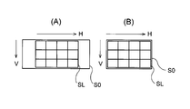
全体光学系の視野(全体視野)が、複数の個眼光学系で得られる視野全体(合成視野)よりも大きいことが好ましい。図5(A),(B)に、全体光学系で得られる全体視野S0と個眼光学系で得られる合成視野SLとの位置関係の例を示す(V:短辺方向,H:長辺方向)。全体光学系で得られる画像情報は、動画やライブビューに用いることができる。動画の画面サイズは16:9であり、ライブビューの画面サイズは撮像装置を搭載する機器(スマートフォン(高機能携帯電話)等)の画像表示装置(例えば、液晶表示装置)の画面サイズであるため、一般的な静止画の画面サイズ4:3(図5(B))と比較して横長(図5(A))になっている。全体光学系が全個眼光学系の一部の領域の画像切り出しであれば、静止画領域の全部を収めることができないので、ライブビューとしては好ましくない。したがって、複数の個眼光学系で得られる合成視野SLよりも、全体光学系で得られる全体視野S0を大きくすることが好ましく、それにより、全体光学系で得られる画像の情報を用いた合成画像の画質を効果的に改善することができる。
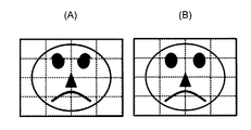
It is preferable that the field of view of the entire optical system (overall field of view) is larger than the entire field of view (synthetic field of view) obtained with a plurality of single-eye optical systems. 5A and 5B show examples of the positional relationship between the overall visual field S0 obtained by the overall optical system and the composite visual field SL obtained by the single-eye optical system (V: short side direction, H: long side). direction). Image information obtained by the entire optical system can be used for moving images and live views. The screen size of the moving image is 16: 9, and the screen size of the live view is the screen size of an image display device (for example, a liquid crystal display device) of a device (smart phone (high-function mobile phone) or the like) equipped with an imaging device. Compared with a general still picture screen size 4: 3 (FIG. 5B), the screen is horizontally long (FIG. 5A). If the entire optical system cuts out an image of a partial area of the all-eye optical system, the entire still image area cannot be accommodated, which is not preferable as a live view. Accordingly, it is preferable to make the overall field of view S0 obtained by the overall optical system larger than the composite field of view SL obtained by a plurality of single-eye optical systems, and thereby, a composite image using image information obtained by the overall optical system. Image quality can be effectively improved.
前記個眼光学系で形成される像を個眼像とするとき、各個眼像の視野の周辺が重なるようになっており、その重なりの量が以下の条件式(1)を満足することが好ましい。
0.01<La/Lb<0.5 …(1)
ただし、
La:重なり量、
Lb:画面の重なる方向の幅、
である。 When an image formed by the single-eye optical system is a single-eye image, the periphery of the field of view of each single-eye image overlaps, and the amount of overlap satisfies the following conditional expression (1). preferable.
0.01 <La / Lb <0.5 (1)
However,
La: overlap amount,
Lb: width in the overlapping direction of the screen,
It is.
複数の個眼像のつなぎ合わせ処理を行うためには、画像のオーバーラップ領域(隣接する個眼光学系で同じ場所を見る領域)が必要であるが、センサーの画素数を有効利用するためにはあまり多くても好ましくない。条件式(1)は、必要なオーバーラップを有しながら、合成画素数を高く保つための好ましい条件を規定している。
In order to perform the process of joining multiple single-eye images, an overlapping area of the image (an area where the same place is seen by the adjacent single-eye optical system) is necessary. In order to effectively use the number of pixels of the sensor Too much is not preferable. Conditional expression (1) defines a preferable condition for keeping the number of synthesized pixels high while having a necessary overlap.
以下の条件式(2)を満足することが好ましい。
-3<F(whole,img)/F(unit,img)<0 …(2)
ただし、
F(unit,img):撮像面に対して垂直な光軸を有する個眼光学系の最も像側のレンズの近軸焦点距離、
F(whole,img):全体光学系の最も像側のレンズの近軸焦点距離、
である。 It is preferable that the following conditional expression (2) is satisfied.
−3 <F (whole, img) / F (unit, img) <0 (2)
However,
F (unit, img): paraxial focal length of the lens on the most image side of the single-eye optical system having an optical axis perpendicular to the imaging surface,
F (hole, img): paraxial focal length of the lens closest to the image side of the entire optical system,
It is.
視野角の広い全体光学系と視野角の狭い(焦点距離の長い)個眼光学系を通常の構成で設計すると、個眼光学系の全長が長くなってしまう。したがって、全体光学系と個眼光学系を同一基板で形成するには設計上の工夫が必要である。同一基板で全体光学系と個眼光学系の両方を成立させるためには、レンズ全長の短縮が行いやすいテレフォトタイプを個眼光学系に採用することが好ましい。その際、全体光学系とのバランスを考慮すると、条件式(2)を満足することが好ましい。条件式(2)の上限を越えると、個眼光学系の全長が長くなりすぎて、全体光学系が大型化したり、同一基板での形成が困難になったりする。条件式(2)の下限を越えると、個眼光学系の負のパワーが大きくなりすぎるために、良好な収差性能を有することが困難になる。
If the whole optical system with a wide viewing angle and the single-eye optical system with a narrow viewing angle (long focal length) are designed with a normal configuration, the total length of the single-eye optical system becomes long. Therefore, design ingenuity is required to form the entire optical system and the single-eye optical system on the same substrate. In order to establish both the entire optical system and the single-eye optical system on the same substrate, it is preferable to adopt a telephoto type that can easily shorten the total lens length for the single-eye optical system. In that case, it is preferable to satisfy the conditional expression (2) in consideration of the balance with the entire optical system. If the upper limit of conditional expression (2) is exceeded, the total length of the single-eye optical system becomes too long, and the overall optical system becomes large, or formation on the same substrate becomes difficult. When the lower limit of conditional expression (2) is exceeded, the negative power of the single-eye optical system becomes too large, making it difficult to have good aberration performance.
以下の条件式(3)を満足することが好ましい。
-2<F(unit,obj)/F(unit,img)<-0.3 …(3)
ただし、
F(unit,obj):撮像面に対して垂直な光軸を有する個眼光学系の最も物体側のレンズの近軸焦点距離、
F(unit,img):撮像面に対して垂直な光軸を有する個眼光学系の最も像側のレンズの近軸焦点距離、
である。 It is preferable that the following conditional expression (3) is satisfied.
-2 <F (unit, obj) / F (unit, img) <-0.3 (3)
However,
F (unit, obj): paraxial focal length of the lens closest to the object side of the single-eye optical system having an optical axis perpendicular to the imaging surface
F (unit, img): paraxial focal length of the lens on the most image side of the single-eye optical system having an optical axis perpendicular to the imaging surface,
It is.
条件式(3)は、全体光学系を同一基板に配置するためのもう一つの条件を規定している。条件式(3)の下限を越えると、物体側のパワーが像側のパワーに対して小さくなるために、テレフォトタイプの特長である小型化のメリットが小さくなる。結果として、全長が大きくなってしまい、薄型化が困難になる。条件式(3)の上限を越えると、各レンズのパワーが強くなりすぎるために収差補正が困難になり、良好な性能を得ることが難しくなる。
Conditional expression (3) defines another condition for placing the entire optical system on the same substrate. If the lower limit of conditional expression (3) is exceeded, the power on the object side becomes smaller than the power on the image side, so the merit of miniaturization, which is a feature of the telephoto type, becomes small. As a result, the overall length becomes large and it is difficult to reduce the thickness. If the upper limit of conditional expression (3) is exceeded, the power of each lens becomes too strong, making it difficult to correct aberrations and making it difficult to obtain good performance.
前記複数の個眼光学系のうち、前記撮像面に対して垂直な光軸を有する個眼光学系(例えば、合成視野の中心部分を構成する個眼光学系)以外のものは、自由曲面を少なくとも1面有する偏心光学系であることが好ましい。視野分割タイプの複眼光学系を薄型化するには、偏心が必要である(厚み増大の原因となる光路変更用プリズムを不要にするため)。しかし、偏心光学系では斜めからの光入射に対して良好に収差補正を行う必要がある。そのような収差補正を行って高性能化を達成するため、偏心面を有する個眼光学系には自由曲面を有することが好ましく、撮像面に対して垂直な光軸を有する個眼光学系以外の全偏心レンズが2面以上の自由曲面を有することが更に好ましい。
Among the plurality of single-eye optical systems, those other than the single-eye optical system having an optical axis perpendicular to the imaging surface (for example, the single-eye optical system constituting the central portion of the combined visual field) have a free-form surface. A decentered optical system having at least one surface is preferable. In order to reduce the thickness of the field division type compound-eye optical system, decentration is necessary (to eliminate the need for an optical path changing prism that causes an increase in thickness). However, in the decentered optical system, it is necessary to correct aberrations satisfactorily for obliquely incident light. In order to achieve high performance by performing such aberration correction, the single-eye optical system having an eccentric surface preferably has a free-form surface, other than the single-eye optical system having an optical axis perpendicular to the imaging surface It is further preferable that all the decentered lenses have two or more free-form surfaces.
前記個眼光学系で形成される像を個眼像とし、前記全体光学系で形成される像を全体像とし、前記撮像素子の撮像面において、前記個眼像が形成される領域を個眼領域とし、前記全体像が形成される領域を全体領域とするとき、各個眼領域の隙間よりも個眼領域と全体領域との隙間の方が大きいことが好ましい。視野分割のために個眼光学系を偏心させようとすると、全体光学系との干渉を避けるために個眼領域と全体領域との間を大きくする必要が生じる。また、個眼光学系の偏心は配置の順に変化するので、個眼光学系同士の干渉は容易に回避可能であるが、個眼光学系と全体光学系との干渉を回避することは困難である。このため、個眼光学系の領域ごとの隙間(例えば0.2mm)よりも個眼領域と全体領域との隙間(例えば2mm)の方を大きくするのが好ましい。そのように構成すれば、そこにクロストークを防ぐための遮光部材を配置できるので、全体光学系は個眼光学系よりもクロストークの影響が小さくなって、非常に良好な画像を得ることができる。
An image formed by the single-eye optical system is a single-eye image, an image formed by the whole optical system is a whole image, and an area where the single-eye image is formed on the imaging surface of the image sensor is a single-eye. When an area is formed and an area where the whole image is formed is an entire area, it is preferable that the gap between the individual eye area and the entire area is larger than the gap between the individual eye areas. When the single-eye optical system is decentered for the field division, it is necessary to increase the distance between the single-eye area and the whole area in order to avoid interference with the whole optical system. In addition, since the eccentricity of the single-eye optical system changes in the order of arrangement, interference between the single-eye optical systems can be easily avoided, but it is difficult to avoid interference between the single-eye optical system and the entire optical system. is there. For this reason, it is preferable to make the gap (for example, 2 mm) between the individual eye area and the entire area larger than the gap (for example, 0.2 mm) for each area of the individual eye optical system. With such a configuration, since a light shielding member for preventing crosstalk can be arranged there, the overall optical system is less affected by crosstalk than a single-eye optical system, and a very good image can be obtained. it can.
前記個眼光学系の数が縦横にそれぞれ3つ以上あり、3×3以上の配列における縦横方向にずれた視野で前記個眼光学系がそれぞれ結像することが好ましい。視野分割で大きな画角を得るには、少なくとも3×3の配列が必要である。
Preferably, the number of the individual optical systems is three or more in the vertical and horizontal directions, and each of the individual optical systems forms an image in a field of view shifted in the vertical and horizontal directions in an array of 3 × 3 or more. In order to obtain a large field angle by dividing the field of view, an arrangement of at least 3 × 3 is required.
複眼光学系は前記両タイプとも撮像装置の薄型化を達成するのに向いているが、視野分割タイプでは一つ一つが小さい視野で撮像を行うので光学系全体の小型化を達成する上で特に有効である。しかし、視野の異なる複数の画像から1つの合成画像を得るには、それぞれの画像がレンズの作用によって反転して撮像素子上に写っているので、個々の画像を回転させてから貼り合わせる画像処理が必要となる。その際、一体に形成されたレンズアレイプレートを用いて、互いに偏心させて異なる視野の撮像を行う光学系を用いた場合には、以下のような課題(1)~(3)がある。
(1):個眼に入射した不要光が隣接センサー面に到達するため、クロストークや面間反射による迷光ゴーストが発生する。
(2):個々のレンズ系のシェーディングが個眼の偏心方向に関係して非対称になるため、貼り合わせの境界での輝度レベルの不一致が発生する。
(3):レンズの調整ズレや被写体距離の差によって理想状態とは異なる視差が発生するため、つなぎ合わせ部分のズレが発生する。 The compound eye optical system is suitable for reducing the thickness of the imaging device in both types, but the field division type performs imaging with a small field of view one by one. It is valid. However, in order to obtain a single composite image from a plurality of images with different fields of view, each image is inverted by the action of the lens and is reflected on the image sensor. Is required. In this case, when using an optical system that uses a lens array plate formed integrally and decenters each other to image different fields of view, there are the following problems (1) to (3).
(1): Unnecessary light incident on a single eye reaches the adjacent sensor surface, and thus stray light ghosts due to crosstalk and inter-surface reflection occur.
(2): Since the shading of the individual lens systems becomes asymmetric with respect to the decentering direction of the individual eye, the brightness level mismatch at the bonding boundary occurs.
(3): Since a parallax different from the ideal state is generated due to a lens adjustment shift or a difference in subject distance, a shift of a joining portion occurs.
これらの課題は個々のレンズ系の情報を用いて対策することもできるが、真の画像の様子は個々のレンズ系の情報だけでは分からないため、その解決には限界がある。そこで、本発明に係る複眼光学系は、複数の個眼光学系で視野の異なる複数の像を撮像面上に形成するとともに、複数の個眼光学系で得られる視野を包含する視野の像を全体光学系で撮像面上に形成する構成としている。全体光学系を有する構成にすることで、真の画像の情報をより正確に求めることが可能となるため、上記の課題(1)~(3)に対して的確な補正を行うことができる。つまり、全体光学系を用いて得られる画像情報から、ゴースト,シェーディング,つなぎ合わせ,歪曲等の不具合を補正することが可能となる。しかも、個眼光学系で形成される像も全体光学系で形成される像も1つの撮像素子上に形成可能なので、撮像装置全体の小型化をより効果的に達成することができる。なお、個々の視野の理想状態(設計値)からのズレを小さくし、かつ撮像装置全体を小型にするためにも、同一の基板に載っていることが好ましい。
These problems can be dealt with by using information of individual lens systems, but since the state of a true image cannot be understood only by the information of individual lens systems, there is a limit to its solution. Therefore, the compound-eye optical system according to the present invention forms a plurality of images having different fields of view with a plurality of single-eye optical systems on the imaging surface, and displays a field-of-view image including the fields of view obtained with the plurality of single-eye optical systems. The entire optical system is formed on the imaging surface. By adopting a configuration having the entire optical system, it is possible to obtain the true image information more accurately, and therefore it is possible to correct the above problems (1) to (3) accurately. That is, it is possible to correct defects such as ghost, shading, stitching, and distortion from image information obtained using the entire optical system. In addition, since the image formed by the single-eye optical system and the image formed by the entire optical system can be formed on one image pickup device, it is possible to more effectively achieve downsizing of the entire image pickup apparatus. In order to reduce the deviation of each field of view from the ideal state (design value) and to reduce the size of the entire imaging apparatus, it is preferable that they are mounted on the same substrate.
前記撮像装置において、画像処理部が全体光学系で得られる画像の情報を用いて合成画像の画質を改善する補正を行うことが好ましい。全体光学系で得られる画像の情報を用いることにより、個眼光学系で得られる像から復元される合成画像(個眼合成画像)の画質を向上させることができる。
In the imaging apparatus, it is preferable that the image processing unit performs correction for improving the image quality of the composite image using image information obtained by the entire optical system. By using image information obtained by the entire optical system, it is possible to improve the image quality of a composite image (single-eye composite image) restored from an image obtained by the single-eye optical system.
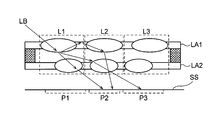
前記全体光学系で得られる画像の情報がゴーストの原因となるクロストークであり、前記画像処理部が前記合成画像で生じたクロストークを特定してゴーストを目立たないように補正することが好ましい。クロストークとは、特定の光学系を射出した光が本来入射すべきセンサー領域とは異なるセンサー領域に入射することをいう。例えば、図6に示すように、レンズアレイプレートLA1,LA2からなるレンズ系L1~L3のうち、レンズ系L1に入射した光LBが、撮像面SSにおいて本来入射すべきセンサー領域P1に入射せず、その周囲のレンズ系L2,L3に入射した後、センサー領域P2,P3に入射することをクロストークという。このようなクロストークは、レンズアレイプレートLA1,LA2のように一体化されたレンズアレイを用いると発生しやすくなる。
It is preferable that the image information obtained by the entire optical system is crosstalk causing ghost, and the image processing unit specifies crosstalk generated in the composite image and corrects the ghost so that it is not noticeable. Crosstalk means that light emitted from a specific optical system is incident on a sensor area different from the sensor area where it should be incident. For example, as shown in FIG. 6, among the lens systems L1 to L3 including the lens array plates LA1 and LA2, the light LB incident on the lens system L1 does not enter the sensor region P1 that should be incident on the imaging surface SS. The incident to the sensor regions P2 and P3 after entering the surrounding lens systems L2 and L3 is called crosstalk. Such crosstalk is likely to occur when an integrated lens array such as the lens array plates LA1 and LA2 is used.
図11のフローチャートにクロストーク補正の制御動作を示す。クロストークの除去では、(1)ゴーストの特定処理と(2)ゴーストの低減処理の2つのステップを実行する。ゴーストの特定処理では、全体画像と複数の個眼像から得られた合成画像との輝度値の比較を行い、その輝度値に大きな差異がある個所(クロストークの発生場所)を特定する(#110)。そして、クロストークがあると判断し(#120)、そのクロストークが補正を要するレベルにあると判断すれば(#130)、クロストークの低減処理(ゴーストの低減処理)を行う(#140)。このクロストーク低減処理では、合成画像から輝度値の差異だけ減算処理を行う。このように、全体光学系で得られた画像情報をクロストーク低減処理に用いることにより、ゴーストが目立たないような効果的な補正を行うことができる。
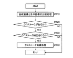
The control operation for crosstalk correction is shown in the flowchart of FIG. In removing crosstalk, two steps of (1) a ghost identification process and (2) a ghost reduction process are executed. In the ghost identification process, the luminance values of the entire image and the synthesized image obtained from a plurality of single-eye images are compared, and a location where the luminance values have a large difference (location where crosstalk occurs) is identified (# 110). If it is determined that there is crosstalk (# 120) and it is determined that the crosstalk is at a level that requires correction (# 130), crosstalk reduction processing (ghost reduction processing) is performed (# 140). . In this crosstalk reduction process, a subtraction process is performed for the difference in luminance value from the composite image. As described above, by using the image information obtained by the entire optical system for the crosstalk reduction process, it is possible to perform an effective correction so that the ghost is not noticeable.
これらの具体的な処理は、例えば特開2012-70443号公報に記述されている。特開2012-70443号公報に記載のものは複眼光学系のクロストーク補正ではないが、画面内に高輝度部がある場合に、ゴーストの発生を予測し、取得画像とのマッチングを行いゴーストの有無を特定し、減算処理で画質改善を行っている。ゴーストの特定処理や減算処理の原理は、本発明におけるクロストーク補正と同様の考え方であるので、これらの処理を適用することでクロストークを補正することができる。また、特開2012-70443公報に記載されているように、特定処理と減算処理の間に除去判断処理を入れてもよい。
These specific processes are described in, for example, Japanese Patent Application Laid-Open No. 2012-70443. The one described in Japanese Patent Application Laid-Open No. 2012-70443 is not a crosstalk correction of a compound eye optical system. However, when there is a high luminance portion in the screen, the occurrence of a ghost is predicted, and matching with an acquired image is performed to match the ghost. The presence or absence is specified, and the image quality is improved by subtraction processing. The principle of the ghost identification process and the subtraction process is the same concept as the crosstalk correction in the present invention, so that the crosstalk can be corrected by applying these processes. Further, as described in JP 2012-70443 A, a removal determination process may be inserted between the specifying process and the subtraction process.
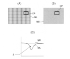
前記全体光学系で得られる画像の情報がシェーディングであり、前記画像処理部が前記全体光学系の画像の輝度分布情報を用いて前記合成画像の輝度分布を補正することが好ましい。図7(A)に個眼合成画像MLの一例を示し、図7(B)に全体画像M0の一例を示す。また、図7(A),(B)中の領域CPでの輝度の変化(Δ:輝度差)を図7(C)に示す。図7(A)に示すように、個眼光学系で得られる照度分布が一様でないために、合成画像の貼り合わせ部分近辺には、個眼光学系のシェーディングによる輝度の不均一が生じることがある。事前のキャリブレーション等である程度の補正を行うことは可能であるが、全ての輝度レベルでの補正を行うことは難しいため、貼り合わせ部分での急激な輝度の変動が残ることがある。全体画像無しには、この変動が被写体によるものか、つなぎ合わせ残りによるものかは判断することができないが、全体光学系で得られた画像情報を用いることにより、これを判定することができ、シェーディングを補正することが可能となる。図8に、(A)シェーディング補正前と(B)シェーディング補正後のグレーチャート撮影結果の一例を示す。
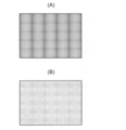
Preferably, the image information obtained by the overall optical system is shading, and the image processing unit corrects the brightness distribution of the composite image using the brightness distribution information of the image of the overall optical system. FIG. 7A shows an example of the single-eye composite image ML, and FIG. 7B shows an example of the entire image M0. In addition, FIG. 7C shows a change in luminance (Δ: luminance difference) in a region CP in FIGS. 7A and 7B. As shown in FIG. 7A, since the illuminance distribution obtained by the single-eye optical system is not uniform, nonuniform luminance due to shading of the single-eye optical system occurs in the vicinity of the stitched portion of the composite image. There is. Although a certain amount of correction can be performed by prior calibration or the like, since it is difficult to perform correction at all luminance levels, there may be a sudden change in luminance at the bonded portion. Without the entire image, it cannot be determined whether this variation is due to the subject or the stitching residue, but this can be determined by using the image information obtained with the entire optical system, Shading can be corrected. FIG. 8 shows an example of a gray chart photographing result before (A) shading correction and after (B) shading correction.
図12のフローチャートにシェーディング補正の制御動作を示す。シェーディング補正では、(1)シェーディング有無の特定と(2)シェーディングの低減処理の2つのステップを実行する。シェーディング有無の特定では、全体画像と複数の個眼像から得られた個眼合成画像との輝度値の比較を行い、その輝度値に大きな差異がある個所(シェーディングの発生場所)を特定する(#210)。特につなぎ目近辺での輝度値を比較し、近傍部分の輝度差を見て、一定量以上であればシェーディング不良が発生していることを特定することができる。例えば、図7に示す(A)個眼合成画像MLと(B)全体画像M0において、四角で囲った領域CPの(つなぎ目近傍)の断面や領域CPの輝度を比較し、その輝度差Δが一定の量以上あれば、シェーディング異常が目立つレベルであると判定することができる。
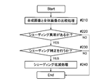
The shading correction control operation is shown in the flowchart of FIG. In the shading correction, two steps are executed: (1) identification of shading presence and (2) shading reduction processing. In specifying shading presence / absence, the luminance values of the whole image and the single-eye composite image obtained from a plurality of single-eye images are compared, and a portion having a large difference in the luminance values (location where shading occurs) is specified ( # 210). In particular, it is possible to identify that a shading failure has occurred if the brightness value in the vicinity of the joint is compared, and the brightness difference in the vicinity is seen to be a certain amount or more. For example, in (A) single-eye composite image ML and (B) whole image M0 shown in FIG. 7, the cross section of the region CP (near the joint) and the luminance of the region CP are compared, and the luminance difference Δ is If it is above a certain amount, it can be determined that the shading abnormality is at a noticeable level.
そして、シェーディング異常があると判断し(#220)、そのシェーディングが補正を要するレベルにあると判断すれば(#230)、シェーディングの低減処理を行う(#240)。このシェーディングの低減処理では、全体画像M0の輝度分布が本来の輝度に近いので、輝度差Δをなくすように個眼合成画像MLの輝度を変化させる。その際に、補正するレベルを調整可能とすることが望ましい。
Then, when it is determined that there is a shading abnormality (# 220) and it is determined that the shading is at a level that requires correction (# 230), shading reduction processing is performed (# 240). In this shading reduction process, since the luminance distribution of the entire image M0 is close to the original luminance, the luminance of the single-eye synthesized image ML is changed so as to eliminate the luminance difference Δ. At that time, it is desirable to be able to adjust the level to be corrected.
前記全体光学系で得られる画像の情報が合成画像のつなぎ目であり、前記画像処理部が前記全体光学系の画像情報を用いて前記合成画像のつなぎ目分布を補正することが好ましい。図9(A)につなぎ補正前の合成画像を示し、図9(B)につなぎ補正後の合成画像を示す。また、図10に、被写体距離の違いによる視差がつなぎ合わせに及ぼす影響を示す。図10(A)は、撮像装置DUで近距離物体NBと基準距離物体FBを撮影している状態を示しており、図10(B)は全体画像M0を示しており、図10(C)は個眼合成画像MLを示している。
It is preferable that image information obtained by the entire optical system is a joint of the composite image, and the image processing unit corrects the joint distribution of the composite image using the image information of the entire optical system. FIG. 9A shows a composite image before connection correction, and FIG. 9B shows a composite image after connection correction. FIG. 10 shows the influence of parallax due to the difference in subject distance on stitching. FIG. 10A shows a state in which the short-distance object NB and the reference distance object FB are photographed by the imaging device DU. FIG. 10B shows the entire image M0, and FIG. Indicates a single-eye composite image ML.
図9及び図10から分かるように、個眼像の貼り合わせにおいては、温度変動によるレンズの中心位置のズレや被写体距離による視差の変動等の影響(隣り合ったレンズ系の視差による距離の違い)で滑らかにつながらない場合が考えられる。合成画像を全体画像と比較することで、この貼り合わせのズレのエラー判定を行うことができる。つまり、被写体が実際に急激に曲がっているのか、貼り合わせのエラーが影響しているのか、について判定することができる。したがって、貼り合わせのエラーと判定された場合には、補正処理を行うこと(画像を動かして位置ズレをなくし、重なりの視野の領域の情報を用いて間を埋めて滑らかなつながりにすること)で、不自然なつなぎ目を補正することができる。
As can be seen from FIGS. 9 and 10, in pasting of single-eye images, the influence of the deviation of the center position of the lens due to temperature variation, the variation of parallax due to subject distance, etc. (the difference in distance due to the parallax between adjacent lens systems) ) Is not connected smoothly. By comparing the composite image with the entire image, it is possible to determine an error in the misalignment of the pasting. That is, it is possible to determine whether the subject is actually bent sharply or whether a pasting error is affecting. Therefore, if it is determined that there is an error in pasting, correction processing is performed (moving the image to eliminate positional deviation, and using the information of the overlapping visual field area to fill in the gap and make a smooth connection) Thus, unnatural joints can be corrected.
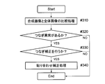
図13のフローチャートにつなぎ補正の制御動作を示す。つなぎ補正では、(1)つなぎ異常の特定処理と(2)貼り合わせ補正処理の2つのステップを実行する。つなぎ異常の特定処理では、全体画像と複数の個眼像から得られた合成画像との輝度値の比較を行い、その輝度値に大きな差異がある個所(つなぎ異常の発生場所)を特定する(#310)。そして、つなぎ異常があると判断し(#320)、そのつなぎ異常が補正を要するレベルにあると判断すれば(#330)、貼り合わせ補正処理(つなぎ異常の低減処理)を行う(#340)。このように、全体光学系で得られた画像情報をつなぎ補正処理に用いることにより、不自然なつなぎ目が目立たないような効果的なつなぎ補正を行うことができる。
Fig. 13 is a flowchart showing the connection correction control operation. In the connection correction, two steps of (1) a connection abnormality specifying process and (2) a bonding correction process are executed. In the joint abnormality identification process, the luminance values of the entire image and the composite image obtained from a plurality of single-eye images are compared, and a portion having a large difference in the luminance values (location where the joint abnormality occurs) is identified ( # 310). If it is determined that there is a joining abnormality (# 320), and it is judged that the joining abnormality is at a level that requires correction (# 330), a bonding correction process (a joining abnormality reducing process) is performed (# 340). . As described above, by using the image information obtained by the entire optical system for the joint correction process, it is possible to perform effective joint correction so that an unnatural joint is not conspicuous.
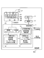
図1に撮像装置の第1の実施の形態を示し、図2に複眼光学系の第1の実施の形態を示し、図3に第1の実施の形態における複眼光学系と撮像領域との位置関係を示す。図1に示すように、撮像装置DUは、撮像ユニットLU,画像処理部1,演算部2,メモリー3等を有している。そして、撮像ユニットLUは、1つの撮像素子SRと、その撮像素子SRに対して視野の異なる複数の結像を行う複眼光学系LHと、を有している。撮像素子SRとしては、例えば複数の画素を有するCCD型イメージセンサー,CMOS型イメージセンサー等の固体撮像素子が用いられる。撮像素子SRの光電変換部である受光面SS上には、被写体の光学像が形成されるように複眼光学系LHが設けられているので、複眼光学系LHによって形成された光学像は、撮像素子SRによって電気的な信号に変換される。
FIG. 1 shows the first embodiment of the imaging apparatus, FIG. 2 shows the first embodiment of the compound-eye optical system, and FIG. 3 shows the positions of the compound-eye optical system and the imaging region in the first embodiment. Show the relationship. As shown in FIG. 1, the imaging device DU includes an imaging unit LU, an image processing unit 1, a calculation unit 2, a memory 3, and the like. The imaging unit LU includes one imaging element SR and a compound-eye optical system LH that performs a plurality of imaging with different fields of view on the imaging element SR. As the image sensor SR, for example, a solid-state image sensor such as a CCD image sensor or a CMOS image sensor having a plurality of pixels is used. Since the compound eye optical system LH is provided on the light receiving surface SS which is a photoelectric conversion unit of the image sensor SR so that an optical image of the subject is formed, the optical image formed by the compound eye optical system LH is captured. It is converted into an electrical signal by the element SR.
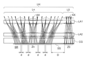
複眼光学系LHは、図1及び図2に示すように、視野の異なる複数の個眼像Zn(n=1,2,3,…)を撮像素子SRの撮像面SS上に形成する複数の個眼光学系Ln(n=1,2,3,…)と、複数の個眼光学系Lnで得られる視野全体を包含する視野の全体像Z0を撮像面SS上に形成する全体光学系L0と、を有している。個眼光学系Ln及び全体光学系L0は、それぞれ物体側レンズと像側レンズとの2枚からなっており、複数の物体側レンズが一体に形成された第1レンズアレイプレートLA1と、複数の像側レンズが一体に形成された第2レンズアレイプレートLA2と、で構成されている。なお、第2レンズアレイプレートLA2の像側には、図2に示すように、撮像素子SRのカバーガラスCGが配置されている。
As shown in FIGS. 1 and 2, the compound-eye optical system LH forms a plurality of single-eye images Zn (n = 1, 2, 3,...) With different fields of view on the imaging surface SS of the imaging element SR. The entire optical system L0 that forms on the imaging surface SS an entire field of view Z0 including the entire field of view obtained by the single-eye optical system Ln (n = 1, 2, 3,...) And the plurality of single-eye optical systems Ln. And have. The single-eye optical system Ln and the entire optical system L0 are each composed of two lenses, an object-side lens and an image-side lens, and a first lens array plate LA1 in which a plurality of object-side lenses are integrally formed, and a plurality of lenses And a second lens array plate LA2 on which the image side lens is integrally formed. Note that a cover glass CG of the imaging element SR is disposed on the image side of the second lens array plate LA2 as shown in FIG.
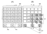
図3(A)では、撮像素子SRの撮像面SSにおいて、個眼光学系Lnで個眼像Znが形成される個眼領域Pn(n=1,2,3,…)と、全体光学系L0で全体像Z0が形成される全体領域P0(P01~P03)と、を撮像領域として示している。図3(B)では、個眼領域Pn(図3(A))に個眼像Zn(図1,図2)を形成する個眼光学系Lnの一部(L13~L15,L18~L20,L23~L25)と、全体領域P0(図3(A))に全体像Z0(図1,図2)を形成する全体光学系L0(L01~L03)と、を更に示している。そして、図3(B)中の円形状は個眼光学系Ln及び全体光学系L0を上方から見た状態(例えば、楕円形状はレンズ系の偏心状態)を示している。なお、図2は図3(B)のQ-Q’線断面図(V方向の1断面)に相当するが、個眼光学系Lnは縦横対称な配置になっているので、図3(B)では9ポジション(L13~L15,L18~L20,L23~L25)の個眼光学系Lnのみを示している。
In FIG. 3A, on the imaging surface SS of the image sensor SR, a single-eye region Pn (n = 1, 2, 3,...) Where the single-eye image Zn is formed by the single-eye optical system Ln, and the entire optical system. An entire region P0 (P01 to P03) where the entire image Z0 is formed at L0 is shown as an imaging region. In FIG. 3B, a part (L13 to L15, L18 to L20, and L18) of a single-eye optical system Ln that forms a single-eye image Zn (FIGS. 1 and 2) in the single-eye region Pn (FIG. 3A). L23 to L25) and the entire optical system L0 (L01 to L03) for forming the entire image Z0 (FIGS. 1 and 2) in the entire region P0 (FIG. 3A) are further shown. The circular shape in FIG. 3B shows a state in which the single-eye optical system Ln and the entire optical system L0 are viewed from above (for example, an elliptical shape is a decentered state of the lens system). 2 corresponds to a cross-sectional view taken along the line QQ ′ of FIG. 3B (one cross section in the V direction), but the single-eye optical system Ln has a vertically and laterally symmetrical arrangement, so FIG. ) Shows only the single-eye optical system Ln in 9 positions (L13 to L15, L18 to L20, L23 to L25).
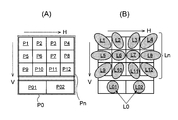
第1の実施の形態では5×5の視野分割を行う構成になっているので、図3から分かるように、個眼光学系Ln及び個眼領域Pnは5×5で対応する配列になっている。中心の個眼光学系L13では被写体中心部分を結像し、周辺の個眼光学系Ln(L13以外)では被写体周辺部分を結像する。ただし、視野分割しているのでいずれの個眼光学系Lnも画角は狭くなっている。
Since the first embodiment is configured to perform 5 × 5 field division, as can be seen from FIG. 3, the single-eye optical system Ln and the single-eye region Pn have a corresponding arrangement of 5 × 5. Yes. The central single-eye optical system L13 forms an image of the subject central portion, and the peripheral single-eye optical system Ln (other than L13) forms an image of the subject peripheral portion. However, since the field of view is divided, the angle of view of any single-eye optical system Ln is narrow.
図2に示すように、個眼光学系Lnはいずれもレンズ2枚構成になっており、図3(B)に示す中心の個眼光学系L13(撮像面SSに対して垂直な光軸AXを有している。)では、正負の望遠タイプのパワー配置になっている。また、中心の個眼光学系L13以外の個眼光学系Lnは、レンズ面が4面とも自由曲面からなっている。自由曲面を4面有する構成により、非常に良好な収差性能を実現することができる。中心の個眼光学系L13以外の個眼光学系Lnは、周辺視野を構成するために光軸AXが偏心しているため、光路変更用のプリズム等を用いる必要がない。したがって、全個眼光学系Lnの厚みを同じにすることができ、同一基板での設計が可能となる。周辺視野を構成する個眼光学系Lnは撮像面SSに対して斜めから光を入射させるので、軸対称光学系と同様の光学性能を得るには自由曲面を4面有することが好ましい。
As shown in FIG. 2, the single-eye optical system Ln has a two-lens configuration, and the central single-eye optical system L13 (optical axis AX perpendicular to the imaging surface SS) shown in FIG. In this case, the power arrangement is a positive / negative telephoto type. Further, in the single-eye optical system Ln other than the central single-eye optical system L13, all four lens surfaces are free-form surfaces. With the configuration having four free-form surfaces, very good aberration performance can be realized. In the single-eye optical system Ln other than the central single-eye optical system L13, the optical axis AX is decentered in order to form the peripheral visual field, so that it is not necessary to use an optical path changing prism or the like. Therefore, the thickness of all the single-eye optical systems Ln can be made the same, and the design on the same substrate becomes possible. Since the single-eye optical system Ln constituting the peripheral visual field makes light incident obliquely with respect to the imaging surface SS, it is preferable to have four free-form surfaces in order to obtain the same optical performance as the axially symmetric optical system.
個眼光学系Lnの下方には、全体光学系L0として同一構成(負正の広角タイプのパワー配置)の3つのレンズ系L01~L03が配置されている。3つの全体光学系L01~L03はいずれも被写体全体を結像させるレンズ系(撮像面SSに対して垂直な光軸AXを有している。)であって、1つの個眼光学系Lnの5倍の画角を有している。また、複眼光学系LHに含まれる全体光学系L0は1つでもよく複数でもよい。全体光学系L0を個眼光学系Lnと共に配置しようとすると、スペースに余裕が生じるので、全体光学系L0を複数配置することが可能である。例えば、複数の全体光学系L0を用いれば、それによって得られた複数の画像を距離情報や3D画像の出力に利用することができる。
Below the single-eye optical system Ln, three lens systems L01 to L03 having the same configuration (negative and positive wide-angle power arrangement) are arranged as the entire optical system L0. Each of the three total optical systems L01 to L03 is a lens system (having an optical axis AX perpendicular to the imaging surface SS) that forms an image of the entire subject, and includes one single-eye optical system Ln. It has 5 times the angle of view. Further, the compound eye optical system LH may include one or a plurality of total optical systems L0. If an attempt is made to arrange the entire optical system L0 together with the single-eye optical system Ln, there is a margin in space, and therefore it is possible to arrange a plurality of entire optical systems L0. For example, if a plurality of whole optical systems L0 are used, a plurality of images obtained thereby can be used for output of distance information and 3D images.
画像処理部1は、画像合成部1aと、画像補正部1bと、出力画像処理部1cと、を有している。画像合成部1aは、複眼光学系LHで形成された視野の異なる複数の個眼像Zn(n=1,2,3,…)をつなぎ合わせて1枚の個眼合成画像ML(図7等)を出力する。その際、反転処理,歪曲処理,シェーディング処理,つなぎ合わせ処理等を行う。画像補正部1bは、全体光学系L0で得られる全体画像M0の情報を用いて個眼合成画像MLの画質を改善する補正を行うことにより、個眼光学系Lnで得られる個眼像Znから復元される個眼合成画像MLの画質を向上させる。つまり、画像補正部1bは、前述したように、個眼合成画像MLで生じたクロストークを特定してゴーストを目立たないように補正したり、全体光学系L0の全体画像M0の輝度分布情報を用いて個眼合成画像MLの輝度分布をシェーディング補正したり、全体光学系L0の画像情報M0を用いて個眼合成画像MLのつなぎ目分布を補正したりする。さらに、必要に応じて歪曲補正も行う。
The image processing unit 1 includes an image composition unit 1a, an image correction unit 1b, and an output image processing unit 1c. The image synthesizing unit 1a connects a plurality of single-eye images Zn (n = 1, 2, 3,...) Formed by the compound-eye optical system LH and having different fields of view to form one single-eye composite image ML (FIG. 7 and the like). ) Is output. At that time, inversion processing, distortion processing, shading processing, stitching processing, and the like are performed. From the single-eye image Zn obtained by the single-eye optical system Ln, the image correction unit 1b performs correction for improving the image quality of the single-eye composite image ML using the information of the whole image M0 obtained by the whole optical system L0. The image quality of the single-eye composite image ML to be restored is improved. That is, as described above, the image correction unit 1b specifies the crosstalk generated in the single-eye composite image ML and corrects the ghost so that it is not conspicuous, or the luminance distribution information of the entire image M0 of the entire optical system L0. The luminance distribution of the single-eye composite image ML is used for shading correction, or the joint distribution of the single-eye composite image ML is corrected using the image information M0 of the entire optical system L0. Further, distortion correction is performed as necessary.
一方、出力画像処理部1cは、全体像Z0を用いた解像度変換及び画質改善を行って全体画像M0を出力する。画像処理部1は、動画出力機能,ライブビュー出力機能及び静止画出力機能を有しているので、静止画出力時には個眼合成画像MLを出力するための画像処理を行うが、動画出力時又はライブビュー出力時には出力画像処理部1cで全体光学系Lnの画像情報を用いた出力を行う。
On the other hand, the output image processing unit 1c performs resolution conversion and image quality improvement using the entire image Z0 and outputs the entire image M0. Since the image processing unit 1 has a moving image output function, a live view output function, and a still image output function, the image processing unit 1 performs image processing for outputting the single-eye composite image ML when outputting a still image. At the time of live view output, the output image processing unit 1c performs output using image information of the entire optical system Ln.
図4に、第2の実施の形態における複眼光学系と撮像領域との位置関係を、図3と対応するように示す。第2の実施の形態では4×3の視野分割を行う構成になっているので、図4から分かるように、個眼光学系Ln及び個眼領域Pnは4×3で対応する配列になっている。全個眼領域Pnの中心には個眼光学系Lnが存在しないので、個眼光学系Lnはいずれも偏心光学系である。個眼光学系Lnの下方には、全体光学系L0として同一構成の2つのレンズ系L01,L02が配置されている。2つの全体光学系L01,L02はいずれも被写体全体を結像させるレンズ系(撮像面SSに対して垂直な光軸AXを有している。)であって、1つの個眼光学系Lnの4倍以上の画角を有している。また、各領域のサイズに関しては、例えば、撮像面SSの画素数を16Mピクセルとすると、個眼領域Pn全体に12Mピクセル、残りを各全体領域P0に2Mピクセルずつ用いることができる。全体光学系L01,L02を用いることで、同じ画角で異なる視差の情報が得られるので、3D画像出力や距離画像出力、さらに超解像画像出力を行ってもよい。本実施の形態では、それぞれ2Mピクセルあるのでハイビジョン画質の3D動画を出力することも可能である。
FIG. 4 shows the positional relationship between the compound eye optical system and the imaging region in the second embodiment so as to correspond to FIG. Since the second embodiment is configured to perform 4 × 3 field division, as can be seen from FIG. 4, the single-eye optical system Ln and the single-eye region Pn are arranged in a corresponding arrangement of 4 × 3. Yes. Since the single-eye optical system Ln does not exist at the center of all the single-eye regions Pn, all the single-eye optical systems Ln are decentered optical systems. Below the single-eye optical system Ln, two lens systems L01 and L02 having the same configuration as the entire optical system L0 are arranged. Each of the two whole optical systems L01 and L02 is a lens system (having an optical axis AX perpendicular to the imaging surface SS) that forms an image of the entire subject, and is composed of one single-eye optical system Ln. It has a field angle more than 4 times. Regarding the size of each region, for example, if the number of pixels on the imaging surface SS is 16M pixels, 12M pixels can be used for the entire single eye region Pn, and the remaining 2M pixels can be used for each entire region P0. By using the entire optical systems L01 and L02, different parallax information can be obtained at the same angle of view, so that 3D image output, distance image output, and super-resolution image output may be performed. In this embodiment, since there are 2M pixels, it is also possible to output a 3D moving image with high-definition image quality.
以下、本発明を実施した複眼光学系の構成等を、コンストラクションデータ等を挙げて更に具体的に説明する。ここで挙げる実施例は、前述した第1の実施の形態に対応する数値実施例であり、複眼光学系LHの第1の実施の形態を表す光学構成図(図2)は、対応する数値実施例のレンズ構成,光路等を示している。
Hereinafter, the configuration of the compound eye optical system embodying the present invention will be described more specifically with reference to construction data. The examples given here are numerical examples corresponding to the above-described first embodiment, and the optical configuration diagram (FIG. 2) representing the first embodiment of the compound-eye optical system LH is a corresponding numerical example. An example lens configuration, optical path, etc. are shown.
表1に、本実施例における個眼光学系Ln及び全体光学系L0のエリア配置を示す。個眼光学系Lnは5×5ポジションに配置されており、全体光学系L0は3ポジションに配置されている。ただし、個眼光学系Lnは縦横対称な配置になっているので、9ポジション(C,V1,V2,H1,H2,D1,D2,VD,HD)のみ示している。
Table 1 shows the area arrangement of the single-eye optical system Ln and the entire optical system L0 in this example. The single-eye optical system Ln is arranged at 5 × 5 positions, and the entire optical system L0 is arranged at three positions. However, since the single-eye optical system Ln has a vertically and horizontally symmetrical arrangement, only 9 positions (C, V1, V2, H1, H2, D1, D2, VD, and HD) are shown.
光軸AXまわりに回転対称な個眼光学系Ln(ポジション:C)や全体光学系L0(ポジション:Zentai)のコンストラクションデータでは、面データとして、左側の欄から順に、面番号,曲率C0(曲率半径の逆数,1/mm),軸上面間隔d(mm),d線(波長:587.56nm)に関する屈折率nd,d線に関するアッベ数vdを示す。また、偏心光学系である個眼光学系Ln(ポジション:V1,VD,D1,V2,D2,HD,H2,H1)のコンストラクションデータでは、面データとして、左側の欄から順に、面番号,曲率C0(曲率半径の逆数,1/mm),軸上面間隔d(mm),Y偏心(mm)を示す。なお、個眼光学系Lnの「90度回転」とは、コンストラクションデータの通りに面を作成して、それをZ軸まわりに90度回した状態がそのレンズの状態になる、ということである。したがって、偏心方向と自由曲面係数に関し、XとYを入れ替えた場合と同じことになる(H方向がX方向に対応し、V方向がY方向に対応する。)。
In the construction data of the single-eye optical system Ln (position: C) and the entire optical system L0 (position: Zentai) that are rotationally symmetric about the optical axis AX, the surface number and curvature C0 (curvature) are sequentially displayed as surface data from the left column. The reciprocal of radius, 1 / mm), the axial distance d (mm), the refractive index nd for the d-line (wavelength: 587.56 nm), and the Abbe number vd for the d-line are shown. In addition, in the construction data of the single-eye optical system Ln (position: V1, VD, D1, V2, D2, HD, H2, H1) that is a decentered optical system, the surface number, curvature, in order from the left column as surface data. C0 (the reciprocal of the radius of curvature, 1 / mm), the shaft upper surface distance d (mm), and the Y eccentricity (mm) are shown. Note that “90 degree rotation” of the single-eye optical system Ln means that a surface is created according to the construction data and rotated 90 degrees around the Z axis to become the lens state. . Therefore, the eccentric direction and the free-form surface coefficient are the same as when X and Y are interchanged (the H direction corresponds to the X direction and the V direction corresponds to the Y direction).
光軸AXまわりに回転対称な個眼光学系Ln(ポジション:C)や全体光学系L0(ポジション:Zentai)には、光軸AXまわりに回転対称な非球面が用いられており、非球面はその面頂点を原点とするローカルな直交座標系(X,Y,Z)を用いた以下の式(AS)で定義される。また、偏心光学系である個眼光学系Ln(ポジション:V1,VD,D1,V2,D2,HD,H2,H1)には、自由曲面が用いられており、自由曲面はその面頂点を原点とするローカルな直交座標系(X,Y,Z)を用いた以下の式(FS)で定義される。非球面データとして非球面係数を示し、自由曲面データとして自由曲面係数を示す(ただし、A(j,k)をXj・Ykで表記する。)。なお、表記の無い項の係数は0であり、すべての非球面についてK=0、すべての自由曲面についてX,Y方向ともK=0であり、すべてのデータに関してE-n=×10-nである。
For the single-eye optical system Ln (position: C) and the entire optical system L0 (position: Zentai) that are rotationally symmetric about the optical axis AX, an aspheric surface that is rotationally symmetric about the optical axis AX is used. It is defined by the following expression (AS) using a local orthogonal coordinate system (X, Y, Z) with the surface vertex as the origin. In addition, a free-form surface is used for the single-eye optical system Ln (position: V1, VD, D1, V2, D2, HD, H2, H1) that is a decentered optical system, and the free-form surface has its surface vertex as the origin. Is defined by the following equation (FS) using a local orthogonal coordinate system (X, Y, Z). The aspheric coefficient is shown as aspheric data, and the free-form surface coefficient is shown as free-form surface data (where A (j, k) is expressed as X j · Y k ). The coefficient of the term not described is 0, K = 0 for all aspheric surfaces, K = 0 in all X and Y directions for all free-form surfaces, and En = × 10 −n for all data. It is.
Z=(C0・h2)/[1+√{1-(1+K)・C02・h2}]+Σ(Ai・hi) …(AS)
Z=(C0・h2)/[1+√{1-(1+K)・C02・h2}]+Σ{A(j,k)・Xj・Yk} …(FS)
ただし、
h:Z軸(光軸AX)に対して垂直な方向の高さ(h2=X2+Y2)、
Z:高さhの位置でのZ軸方向の変位量(面頂点基準)、
C0:面頂点での曲率(曲率半径の逆数)、
K:円錐定数、
Ai:i次の非球面係数、
A(j,k):Xのj次、Yのk次の自由曲面係数、
である。 Z = (C0 · h 2 ) / [1 + √ {1− (1 + K) · C0 2 · h 2 }] + Σ (Ai · h i ) (AS)
Z = (C0 · h 2 ) / [1 + √ {1− (1 + K) · C0 2 · h 2 }] + Σ {A (j, k) · X j · Y k } (FS)
However,
h: height in a direction perpendicular to the Z axis (optical axis AX) (h 2 = X 2 + Y 2 ),
Z: Displacement amount in the Z-axis direction at the position of height h (based on the surface vertex),
C0: curvature at the surface apex (the reciprocal of the radius of curvature),
K: conic constant,
Ai: i-th order aspheric coefficient,
A (j, k): j-th free surface coefficient of X, k-th free surface coefficient of Y,
It is.
撮像ユニットLUに関する各種データを以下に示す(図1~図3等)。
Fno:3.2相当
個眼領域Pnの間隔d=0.2mm
個眼領域Pnと全体領域P0との間隔D=2mm
個眼領域Pn全体のサイズ:5.6mm×4.2mm
各個眼領域Pnのサイズ:1.07×0.79mm
各個眼領域Pnの画素数:Lb=743×543ピクセル(1.12μmピッチ)
各全体領域P0のサイズ:1.43mm×0.81mm
各全体領域P0の画素数:1280×720ピクセル
被写体の重なり画素数:La=40ピクセル(被写体距離:2m)
条件式(1):La/Lb=40/743=0.054
条件式(1):La/Lb=40/543=0.074 Various data relating to the imaging unit LU are shown below (FIGS. 1 to 3 and the like).
Fno: 3.2 equivalent single eye region Pn interval d = 0.2 mm
Interval D = 2mm between single-eye region Pn and entire region P0
Total size of the single eye area Pn: 5.6 mm × 4.2 mm
Size of each individual eye region Pn: 1.07 × 0.79 mm
Number of pixels in each individual eye region Pn: Lb = 743 × 543 pixels (1.12 μm pitch)
Size of each whole area P0: 1.43 mm × 0.81 mm
Number of pixels in each whole area P0: 1280 × 720 pixels Number of overlapping pixels of subject: La = 40 pixels (subject distance: 2 m)
Conditional expression (1): La / Lb = 40/743 = 0.054
Conditional expression (1): La / Lb = 40/543 = 0.074
個眼光学系Ln及び全体光学系L0を構成する2枚のレンズのデータを以下に示す(図2等)。
[近軸焦点距離] 物体側レンズ(LA1) 像側レンズ(LA2)
全体光学系 1.72mm 1.54mm
個眼光学系(中心) 2.09mm -2.01mm
条件式(2):F(whole,img)/F(unit,img)
=1.54/-2.01=-0.77
条件式(3):F(unit,obj)/F(unit,img)
=2.09/-2.01=-1.04 Data of the two lenses constituting the single-eye optical system Ln and the entire optical system L0 are shown below (FIG. 2 and the like).
[Paraxial focal length] Object side lens (LA1) Image side lens (LA2)
Overall optical system 1.72mm 1.54mm
Single eye optical system (center) 2.09mm -2.01mm
Conditional expression (2): F (hole, img) / F (unit, img)
= 1.54 / -2.01 = -0.77
Conditional expression (3): F (unit, obj) / F (unit, img)
= 2.09 / -2.01 = -1.04

ポジション:C
単位:mm
面データ
面番号 C0 d nd vd
1 1.534928 0.215 1.5178 56.1
2 0 0.305 1.5100 62.4
3 0 0.050 1.6020 28.6
4 0.7509255 0.850
5 -0.354405 0.050 1.6020 28.6
6 0 0.300 1.5100 62.4
7 0 0.050 1.5178 56.1
8 0.5121223 0.150
9 0 0.500 1.4714 66.02
10 0 0.050 Position: C
Unit: mm
Surface data Surface number C0 d nd vd
1 1.534928 0.215 1.5178 56.1
2 0 0.305 1.5 100 62.4
3 0 0.050 1.6020 28.6
4 0.7509255 0.850
5 -0.354405 0.050 1.6020 28.6
6 0 0.300 1.5 100 62.4
7 0 0.050 1.5178 56.1
8 0.5121223 0.150
9 0 0.500 1.4714 66.02
10 0 0.050
非球面係数
第1面
A4 = 9.314E-03
A6 = 1.905E+00
A8 = -7.387E+00
A10= 7.279E+00
A12= 6.976E+01
A14= 5.992E+01
A16= -6.976E+02
A18= 0.000E+00 Aspherical coefficient 1st surface A4 = 9.314E-03
A6 = 1.905E + 00
A8 = -7.387E + 00
A10 = 7.279E + 00
A12 = 6.976E + 01
A14 = 5.992E + 01
A16 = -6.976E + 02
A18 = 0.000E + 00
非球面係数
第4面
A4 = 2.155E-01
A6 = -1.015E+00
A8 = 1.017E+01
A10= 3.338E+01
A12= -5.537E+02
A14= -1.397E+03
A16= 9.251E+03
A18= 0.000E+00 Aspheric coefficient 4th surface A4 = 2.155E-01
A6 = -1.015E + 00
A8 = 1.017E + 01
A10 = 3.338E + 01
A12 = -5.537E + 02
A14 = -1.397E + 03
A16 = 9.251E + 03
A18 = 0.000E + 00
非球面係数
第5面
A4 = -1.146E+00
A6 = 6.744E+00
A8 = -6.907E+01
A10= 2.998E+02
A12= 3.951E-05
A14= 3.461E-05
A16= 3.316E-05
A18= 0.000E+00 Aspherical coefficient 5th surface A4 = -1.146E + 00
A6 = 6.744E + 00
A8 = -6.907E + 01
A10 = 2.998E + 02
A12 = 3.951E-05
A14 = 3.461E-05
A16 = 3.316E-05
A18 = 0.000E + 00
第5面
A4 = -1.146E+00
A6 = 6.744E+00
A8 = -6.907E+01
A10= 2.998E+02
A12= 3.951E-05
A14= 3.461E-05
A16= 3.316E-05
A18= 0.000E+00 Aspherical coefficient 5th surface A4 = -1.146E + 00
A6 = 6.744E + 00
A8 = -6.907E + 01
A10 = 2.998E + 02
A12 = 3.951E-05
A14 = 3.461E-05
A16 = 3.316E-05
A18 = 0.000E + 00
非球面係数
第8面
A4 = -1.468E+00
A6 = 1.973E+01
A8 = -3.199E+02
A10= 3.147E+03
A12= -1.691E+04
A14= 4.276E+04
A16= -2.996E+04
A18= 0.000E+00 Aspheric coefficient 8th surface A4 = -1.468E + 00
A6 = 1.973E + 01
A8 = -3.199E + 02
A10 = 3.147E + 03
A12 = -1.691E + 04
A14 = 4.276E + 04
A16 = -2.996E + 04
A18 = 0.000E + 00
ポジション:V1
単位:mm
面データ
面番号 C0 d Y偏心
1 0.9527951 0.198 0.000
2 0 0.305 0.044
3 0 0.050 0.044
4 1.2505431 0.826 0.077
5 1.3377381 0.074 0.484
6 0 0.300 0.484
7 0 0.058 0.484
8 -2.338101 0.142 0.699
9 0 0.500 0.890
10 0 0.050 0.890 Position: V1
Unit: mm
Surface data Surface number C0d Y Eccentric 1 0.9527951 0.198 0.000
2 0 0.305 0.044
3 0 0.050 0.044
4 1.2505431 0.826 0.077
5 1.3377381 0.074 0.484
6 0 0.300 0.484
7 0 0.058 0.484
8 -2.338101 0.142 0.699
9 0 0.500 0.890
10 0 0.050 0.890
単位:mm
面データ
面番号 C0 d Y偏心
1 0.9527951 0.198 0.000
2 0 0.305 0.044
3 0 0.050 0.044
4 1.2505431 0.826 0.077
5 1.3377381 0.074 0.484
6 0 0.300 0.484
7 0 0.058 0.484
8 -2.338101 0.142 0.699
9 0 0.500 0.890
10 0 0.050 0.890 Position: V1
Unit: mm
Surface data Surface number C0
2 0 0.305 0.044
3 0 0.050 0.044
4 1.2505431 0.826 0.077
5 1.3377381 0.074 0.484
6 0 0.300 0.484
7 0 0.058 0.484
8 -2.338101 0.142 0.699
9 0 0.500 0.890
10 0 0.050 0.890
自由曲面係数
第1面
Y = -3.953E-02 , X2 = 2.900E-01 , Y2 = 2.953E-01 ,
X2Y = 5.393E-03 , Y3 = 8.977E-03 , X4 = 3.088E-01 ,
X2Y2 = 6.843E-01 , Y4 = 2.743E-01 , X4Y = 2.576E-02 ,
X2Y3 = -6.297E-02 , Y5 = -1.055E-02 , X6 = 5.192E-01 ,
X4Y2 = 1.088E+00 , X2Y4 = 6.341E-01 , Y6 = 2.794E-01 ,
X6Y = 1.828E-01 , X4Y3 = -6.036E-01 , X2Y5 = 7.031E-02 ,
Y7 = 5.121E-01 , X8 = 3.359E-01 , X6Y2 = 3.933E+00 ,
X4Y4 = 1.816E+01 , X2Y6 = 1.070E+01 , Y8 = 5.975E-01 ,
X8Y = 1.097E-02 , X6Y3 = 6.167E+00 , X4Y5 = 7.030E+00 ,
X2Y7 = 7.967E-01 , Y9 = -5.618E-01 , X10 = 3.461E+00 ,
X8Y2 = 1.459E+01 , X6Y4 = -4.572E+01 , X4Y6 = -7.086E+01 ,
X2Y8 = -2.802E+01 Free-form surface coefficient 1st surface Y = -3.953E-02, X2 = 2.900E-01, Y2 = 2.953E-01,
X2Y = 5.393E-03, Y3 = 8.977E-03, X4 = 3.088E-01,
X2Y2 = 6.843E-01, Y4 = 2.743E-01, X4Y = 2.576E-02,
X2Y3 = -6.297E-02, Y5 = -1.055E-02, X6 = 5.192E-01,
X4Y2 = 1.088E + 00, X2Y4 = 6.341E-01, Y6 = 2.794E-01,
X6Y = 1.828E-01, X4Y3 = -6.036E-01, X2Y5 = 7.031E-02,
Y7 = 5.121E-01, X8 = 3.359E-01, X6Y2 = 3.933E + 00,
X4Y4 = 1.816E + 01, X2Y6 = 1.070E + 01, Y8 = 5.975E-01,
X8Y = 1.097E-02, X6Y3 = 6.167E + 00, X4Y5 = 7.030E + 00,
X2Y7 = 7.967E-01, Y9 = -5.618E-01, X10 = 3.461E + 00,
X8Y2 = 1.459E + 01, X6Y4 = -4.572E + 01, X4Y6 = -7.086E + 01,
X2Y8 = -2.802E + 01
自由曲面係数
第4面
Y = -5.516E-03 , X2 = -1.491E-01 , Y2 = -1.735E-01 ,
X2Y = 3.365E-01 , Y3 = 4.063E-01 , X4 = 2.486E-01 ,
X2Y2 = 9.696E-01 , Y4 = 3.255E-01 , X4Y = 8.729E-01 ,
X2Y3 = 1.784E+00 , Y5 = 9.510E-01 , X6 = 3.980E+00 ,
X4Y2 = 1.188E+01 , X2Y4 = 1.168E+01 , Y6 = 4.123E+00 ,
X6Y = 7.692E+00 , X4Y3 = 3.888E+00 , X2Y5 = 8.452E+00 ,
Y7 = 1.886E+00 , X8 = -3.478E+01 , X6Y2 = -1.315E+02 ,
X4Y4 = -2.233E+02 , X2Y6 = -1.491E+02 , Y8 = -4.374E+01 ,
X8Y = 4.733E+00 , X6Y3 = 1.695E+02 , X4Y5 = 2.768E+02 ,
X2Y7 = 1.064E+02 , Y9 = 3.424E+01 , X10 = 2.197E+02 ,
X8Y2 = 1.099E+03 , X6Y4 = 2.487E+03 , X4Y6 = 2.746E+03 ,
X2Y8 = 1.312E+03 , Y10 = 2.927E+02 Free-form surface coefficient 4th surface Y = -5.516E-03, X2 = -1.491E-01, Y2 = -1.735E-01,
X2Y = 3.365E-01, Y3 = 4.063E-01, X4 = 2.486E-01,
X2Y2 = 9.696E-01, Y4 = 3.255E-01, X4Y = 8.729E-01,
X2Y3 = 1.784E + 00, Y5 = 9.510E-01, X6 = 3.980E + 00,
X4Y2 = 1.188E + 01, X2Y4 = 1.168E + 01, Y6 = 4.123E + 00,
X6Y = 7.692E + 00, X4Y3 = 3.888E + 00, X2Y5 = 8.452E + 00,
Y7 = 1.886E + 00, X8 = -3.478E + 01, X6Y2 = -1.315E + 02,
X4Y4 = -2.233E + 02, X2Y6 = -1.491E + 02, Y8 = -4.374E + 01,
X8Y = 4.733E + 00, X6Y3 = 1.695E + 02, X4Y5 = 2.768E + 02,
X2Y7 = 1.064E + 02, Y9 = 3.424E + 01, X10 = 2.197E + 02,
X8Y2 = 1.099E + 03, X6Y4 = 2.487E + 03, X4Y6 = 2.746E + 03,
X2Y8 = 1.312E + 03, Y10 = 2.927E + 02
自由曲面係数
第5面
Y = 2.497E-02 , X2 = -2.321E-01 , Y2 = -5.041E-01 ,
X2Y = -6.330E-01 , Y3 = -1.621E-01 , X4 = -1.808E+00 ,
X2Y2 = -1.465E+00 , Y4 = -1.278E+00 , X4Y = 2.683E-01 ,
X2Y3 = 2.795E+00 , Y5 = 2.758E-01 , X6 = 5.808E+00 ,
X4Y2 = 7.502E-01 , X2Y4 = 8.454E+00 , Y6 = 1.011E+01 ,
X6Y = 2.889E+00 , X4Y3 = 4.274E+00 , X2Y5 = -3.082E+00 ,
Y7 = 2.278E+01 , X8 = -5.127E+01 , X6Y2 = -1.478E+01 ,
X4Y4 = 6.967E+01 , X2Y6 = -1.326E+02 , Y8 = -8.045E+01 ,
X8Y = 4.752E+01 , X6Y3 = 7.582E+01 , X4Y5 = 8.368E+01 ,
X2Y7 = 1.474E+02 , Y9 = -6.233E+01 , X10 = 1.544E+02 ,
X8Y2 = 7.403E+01 , X6Y4 = -6.087E+02 , X4Y6 = -1.080E+02 ,
X2Y8 = 2.065E+02 , Y10 = 8.294E+01 Free-form surface coefficient Fifth surface Y = 2.497E-02, X2 = -2.321E-01, Y2 = -5.041E-01,
X2Y = -6.330E-01, Y3 = -1.621E-01, X4 = -1.808E + 00,
X2Y2 = -1.465E + 00, Y4 = -1.278E + 00, X4Y = 2.683E-01,
X2Y3 = 2.795E + 00, Y5 = 2.758E-01, X6 = 5.808E + 00,
X4Y2 = 7.502E-01, X2Y4 = 8.454E + 00, Y6 = 1.011E + 01,
X6Y = 2.889E + 00, X4Y3 = 4.274E + 00, X2Y5 = -3.082E + 00,
Y7 = 2.278E + 01, X8 = -5.127E + 01, X6Y2 = -1.478E + 01,
X4Y4 = 6.967E + 01, X2Y6 = -1.326E + 02, Y8 = -8.045E + 01,
X8Y = 4.752E + 01, X6Y3 = 7.582E + 01, X4Y5 = 8.368E + 01,
X2Y7 = 1.474E + 02, Y9 = -6.233E + 01, X10 = 1.544E + 02,
X8Y2 = 7.403E + 01, X6Y4 = -6.087E + 02, X4Y6 = -1.080E + 02,
X2Y8 = 2.065E + 02, Y10 = 8.294E + 01
自由曲面係数
第8面
Y = 1.224E-01 , X2 = 2.075E+00 , Y2 = 1.383E+00 ,
X2Y = -1.512E+00 , Y3 = -7.844E-01 , X4 = -1.540E+00 ,
X2Y2 = 3.547E+00 , Y4 = 1.814E+00 , X4Y = 1.920E+00 ,
X2Y3 = 4.295E+00 , Y5 = 7.072E+00 , X6 = 3.319E+01 ,
X4Y2 = 8.159E+01 , X2Y4 = 1.309E+01 , Y6 = 2.509E+01 ,
X6Y = -2.759E+01 , X4Y3 = 1.380E+01 , X2Y5 = -7.415E+01 ,
Y7 = 2.341E+01 , X8 = -2.258E+02 , X6Y2 = -8.530E+02 ,
X4Y4 = -6.766E+02 , X2Y6 = 9.905E+00 , Y8 = -2.225E+02 ,
X8Y = 1.344E+02 , X6Y3 = 1.638E+02 , X4Y5 = 1.627E+02 ,
X2Y7 = 8.391E+02 , Y9 = -1.233E+03 , X10 = 1.038E+03 ,
X8Y2 = 4.350E+03 , X6Y4 = 7.412E+03 , X4Y6 = 5.571E+03 ,
X2Y8 = 1.823E+03 , Y10 = -1.666E+03 Free surface coefficient 8th surface Y = 1.224E-01, X2 = 2.075E + 00, Y2 = 1.383E + 00,
X2Y = -1.512E + 00, Y3 = -7.844E-01, X4 = -1.540E + 00,
X2Y2 = 3.547E + 00, Y4 = 1.814E + 00, X4Y = 1.920E + 00,
X2Y3 = 4.295E + 00, Y5 = 7.072E + 00, X6 = 3.319E + 01,
X4Y2 = 8.159E + 01, X2Y4 = 1.309E + 01, Y6 = 2.509E + 01,
X6Y = -2.759E + 01, X4Y3 = 1.380E + 01, X2Y5 = -7.415E + 01,
Y7 = 2.341E + 01, X8 = -2.258E + 02, X6Y2 = -8.530E + 02,
X4Y4 = -6.766E + 02, X2Y6 = 9.905E + 00, Y8 = -2.225E + 02,
X8Y = 1.344E + 02, X6Y3 = 1.638E + 02, X4Y5 = 1.627E + 02,
X2Y7 = 8.391E + 02, Y9 = -1.233E + 03, X10 = 1.038E + 03,
X8Y2 = 4.350E + 03, X6Y4 = 7.412E + 03, X4Y6 = 5.571E + 03,
X2Y8 = 1.823E + 03, Y10 = -1.666E + 03
ポジション:V2
単位:mm
面データ
面番号 C0 d Y偏心
1 1.0937088 0.228 0.000
2 0 0.305 0.011
3 0 0.065 0.011
4 1.2847229 0.764 0.022
5 0.5588239 0.119 0.210
6 0 0.300 0.210
7 0 0.050 0.210
8 -2.429775 0.150 0.338
9 0 0.500 0.445
10 0 0.050 0.445 Position: V2
Unit: mm
Surface data Surface number C0d Y Eccentric 1 1.0937088 0.228 0.000
2 0 0.305 0.011
3 0 0.065 0.011
4 1.2847229 0.764 0.022
5 0.5588239 0.119 0.210
6 0 0.300 0.210
7 0 0.050 0.210
8 -2.429775 0.150 0.338
9 0 0.500 0.445
10 0 0.050 0.445
単位:mm
面データ
面番号 C0 d Y偏心
1 1.0937088 0.228 0.000
2 0 0.305 0.011
3 0 0.065 0.011
4 1.2847229 0.764 0.022
5 0.5588239 0.119 0.210
6 0 0.300 0.210
7 0 0.050 0.210
8 -2.429775 0.150 0.338
9 0 0.500 0.445
10 0 0.050 0.445 Position: V2
Unit: mm
Surface data Surface number C0
2 0 0.305 0.011
3 0 0.065 0.011
4 1.2847229 0.764 0.022
5 0.5588239 0.119 0.210
6 0 0.300 0.210
7 0 0.050 0.210
8 -2.429775 0.150 0.338
9 0 0.500 0.445
10 0 0.050 0.445
自由曲面係数
第1面
Y = -2.084E-02 , X2 = 2.206E-01 , Y2 = 2.262E-01 ,
X2Y = -6.550E-02 , Y3 = -1.305E-02 , X4 = 2.369E-01 ,
X2Y2 = 6.352E-01 , Y4 = 2.219E-01 , X4Y = -7.399E-03 ,
X2Y3 = -1.586E-02 , Y5 = 6.438E-04 , X6 = 9.268E-02 ,
X4Y2 = 4.614E-01 , X2Y4 = 9.744E-01 , Y6 = 3.951E-01 ,
X6Y = -2.694E-01 , X4Y3 = -7.160E-01 , X2Y5 = -2.124E-01 ,
Y7 = 4.055E-01 , X8 = 1.929E+00 , X6Y2 = 8.739E+00 ,
X4Y4 = 1.386E+01 , X2Y6 = 6.597E+00 , Y8 = 1.099E+00 ,
X8Y = 5.560E-02 , X6Y3 = 2.631E-01 , X4Y5 = 3.563E+00 ,
X2Y7 = 9.587E-01 , Y9 = 6.218E-02 , X10 = 1.823E-01 ,
X8Y2 = 2.736E+00 , X6Y4 = 4.164E+00 , X4Y6 = 3.366E+00 ,
X2Y8 = -1.746E+00 , Y10 = -3.665E-02 Free-form surface coefficient 1st surface Y = -2.084E-02, X2 = 2.206E-01, Y2 = 2.262E-01,
X2Y = -6.550E-02, Y3 = -1.305E-02, X4 = 2.369E-01,
X2Y2 = 6.352E-01, Y4 = 2.219E-01, X4Y = -7.399E-03,
X2Y3 = -1.586E-02, Y5 = 6.438E-04, X6 = 9.268E-02,
X4Y2 = 4.614E-01, X2Y4 = 9.744E-01, Y6 = 3.951E-01,
X6Y = -2.694E-01, X4Y3 = -7.160E-01, X2Y5 = -2.124E-01,
Y7 = 4.055E-01, X8 = 1.929E + 00, X6Y2 = 8.739E + 00,
X4Y4 = 1.386E + 01, X2Y6 = 6.597E + 00, Y8 = 1.099E + 00,
X8Y = 5.560E-02, X6Y3 = 2.631E-01, X4Y5 = 3.563E + 00,
X2Y7 = 9.587E-01, Y9 = 6.218E-02, X10 = 1.823E-01,
X8Y2 = 2.736E + 00, X6Y4 = 4.164E + 00, X4Y6 = 3.366E + 00,
X2Y8 = -1.746E + 00, Y10 = -3.665E-02
自由曲面係数
第4面
Y = -1.011E-01 , X2 = -1.456E-01 , Y2 = -2.008E-01 ,
X2Y = -1.783E-01 , Y3 = 1.011E-01 , X4 = 3.027E-01 ,
X2Y2 = 1.578E+00 , Y4 = 4.006E-01 , X4Y = 6.951E-01 ,
X2Y3 = 1.078E+00 , Y5 = 5.638E-01 , X6 = -4.986E-01 ,
X4Y2 = -6.200E+00 , X2Y4 = -8.856E+00 , Y6 = -3.808E+00 ,
X6Y = -8.530E+00 , X4Y3 = -2.013E+01 , X2Y5 = -3.285E+00 ,
Y7 = 1.847E+00 , X8 = 1.750E+01 , X6Y2 = 1.164E+02 ,
X4Y4 = 2.235E+02 , X2Y6 = 1.354E+02 , Y8 = 3.227E+01 ,
X8Y = 1.458E+01 , X6Y3 = 2.008E+01 , X4Y5 = 7.803E+01 ,
X2Y7 = 1.545E+00 , Y9 = 2.166E+00 , X10 = 2.547E+00 ,
X8Y2 = 7.595E+01 , X6Y4 = 1.214E+02 , X4Y6 = 1.801E+02 ,
X2Y8 = 3.141E+01 , Y10 = 4.010E+00 Free-form surface coefficient 4th surface Y = -1.011E-01, X2 = -1.456E-01, Y2 = -2.008E-01,
X2Y = -1.783E-01, Y3 = 1.011E-01, X4 = 3.027E-01,
X2Y2 = 1.578E + 00, Y4 = 4.006E-01, X4Y = 6.951E-01,
X2Y3 = 1.078E + 00, Y5 = 5.638E-01, X6 = -4.986E-01,
X4Y2 = -6.200E + 00, X2Y4 = -8.856E + 00, Y6 = -3.808E + 00,
X6Y = -8.530E + 00, X4Y3 = -2.013E + 01, X2Y5 = -3.285E + 00,
Y7 = 1.847E + 00, X8 = 1.750E + 01, X6Y2 = 1.164E + 02,
X4Y4 = 2.235E + 02, X2Y6 = 1.354E + 02, Y8 = 3.227E + 01,
X8Y = 1.458E + 01, X6Y3 = 2.008E + 01, X4Y5 = 7.803E + 01,
X2Y7 = 1.545E + 00, Y9 = 2.166E + 00, X10 = 2.547E + 00,
X8Y2 = 7.595E + 01, X6Y4 = 1.214E + 02, X4Y6 = 1.801E + 02,
X2Y8 = 3.141E + 01, Y10 = 4.010E + 00
自由曲面係数
第5面
Y = -1.687E-01 , X2 = 1.535E-01 , Y2 = -1.860E-01 ,
X2Y = -9.135E-01 , Y3 = -4.695E-01 , X4 = -1.810E+00 ,
X2Y2 = -1.126E+00 , Y4 = -2.371E+00 , X4Y = -1.979E-02 ,
X2Y3 = 1.917E+00 , Y5 = -6.368E-01 , X6 = 5.304E+00 ,
X4Y2 = 7.163E+00 , X2Y4 = -1.325E+00 , Y6 = 1.064E+01 ,
X6Y = 1.209E+00 , X4Y3 = -8.162E+00 , X2Y5 = -1.824E+01 ,
Y7 = 2.992E+01 , X8 = -4.385E+01 , X6Y2 = -5.348E+01 ,
X4Y4 = 7.966E+01 , X2Y6 = -9.465E+01 , Y8 = -1.803E+02 ,
X8Y = 5.740E+00 , X6Y3 = 2.414E+01 , X4Y5 = 2.081E+02 ,
X2Y7 = 1.190E+01 , Y9 = -2.409E+02 , X10 = 1.338E+02 ,
X8Y2 = -4.378E+01 , X6Y4 = -4.346E+02 , X4Y6 = -1.124E+01 ,
X2Y8 = 3.977E+02 , Y10 = 7.657E+02 Free-form surface coefficient Fifth surface Y = -1.687E-01, X2 = 1.535E-01, Y2 = -1.860E-01,
X2Y = -9.135E-01, Y3 = -4.695E-01, X4 = -1.810E + 00,
X2Y2 = -1.126E + 00, Y4 = -2.371E + 00, X4Y = -1.979E-02,
X2Y3 = 1.917E + 00, Y5 = -6.368E-01, X6 = 5.304E + 00,
X4Y2 = 7.163E + 00, X2Y4 = -1.325E + 00, Y6 = 1.064E + 01,
X6Y = 1.209E + 00, X4Y3 = -8.162E + 00, X2Y5 = -1.824E + 01,
Y7 = 2.992E + 01, X8 = -4.385E + 01, X6Y2 = -5.348E + 01,
X4Y4 = 7.966E + 01, X2Y6 = -9.465E + 01, Y8 = -1.803E + 02,
X8Y = 5.740E + 00, X6Y3 = 2.414E + 01, X4Y5 = 2.081E + 02,
X2Y7 = 1.190E + 01, Y9 = -2.409E + 02, X10 = 1.338E + 02,
X8Y2 = -4.378E + 01, X6Y4 = -4.346E + 02, X4Y6 = -1.124E + 01,
X2Y8 = 3.977E + 02, Y10 = 7.657E + 02
自由曲面係数
第8面
Y = 1.089E-02 , X2 = 2.288E+00 , Y2 = 1.653E+00 ,
X2Y = -1.653E+00 , Y3 = -1.171E+00 , X4 = -1.421E+00 ,
X2Y2 = 3.507E+00 , Y4 = -8.067E-01 , X4Y = 1.342E+00 ,
X2Y3 = 5.001E+00 , Y5 = 5.026E+00 , X6 = 2.139E+01 ,
X4Y2 = 8.740E+01 , X2Y4 = 3.560E+01 , Y6 = 2.333E+01 ,
X6Y = 1.126E+01 , X4Y3 = -3.083E+01 , X2Y5 = -4.244E+01 ,
Y7 = 1.486E+01 , X8 = -1.213E+02 , X6Y2 = -8.605E+02 ,
X4Y4 = -8.703E+02 , X2Y6 = -3.927E+02 , Y8 = -1.100E+02 ,
X8Y = -1.495E+02 , X6Y3 = 2.230E+02 , X4Y5 = 1.423E+02 ,
X2Y7 = -8.262E+01 , Y9 = -1.953E+02 , X10 = 1.040E+03 ,
X8Y2 = 4.701E+03 , X6Y4 = 1.042E+04 , X4Y6 = 8.246E+03 ,
X2Y8 = 2.386E+03 , Y10 = 4.922E+02 Free surface coefficient 8th surface Y = 1.089E-02, X2 = 2.288E + 00, Y2 = 1.653E + 00,
X2Y = -1.653E + 00, Y3 = -1.171E + 00, X4 = -1.421E + 00,
X2Y2 = 3.507E + 00, Y4 = -8.067E-01, X4Y = 1.342E + 00,
X2Y3 = 5.001E + 00, Y5 = 5.026E + 00, X6 = 2.139E + 01,
X4Y2 = 8.740E + 01, X2Y4 = 3.560E + 01, Y6 = 2.333E + 01,
X6Y = 1.126E + 01, X4Y3 = -3.083E + 01, X2Y5 = -4.244E + 01,
Y7 = 1.486E + 01, X8 = -1.213E + 02, X6Y2 = -8.605E + 02,
X4Y4 = -8.703E + 02, X2Y6 = -3.927E + 02, Y8 = -1.100E + 02,
X8Y = -1.495E + 02, X6Y3 = 2.230E + 02, X4Y5 = 1.423E + 02,
X2Y7 = -8.262E + 01, Y9 = -1.953E + 02, X10 = 1.040E + 03,
X8Y2 = 4.701E + 03, X6Y4 = 1.042E + 04, X4Y6 = 8.246E + 03,
X2Y8 = 2.386E + 03, Y10 = 4.922E + 02
ポジション:H1(90度回転)
単位:mm
面データ
面番号 C0 d Y偏心
1 1.0256853 0.132 0.000
2 0 0.305 0.034
3 0 0.050 0.034
4 1.1274901 0.849 0.058
5 1.1551341 0.051 0.660
6 0 0.300 0.660
7 0 0.075 0.660
8 -2.401183 0.124 0.917
9 0 0.500 1.177
10 0 0.050 1.177 Position: H1 (90 degree rotation)
Unit: mm
Surface data Surface number C0d Y Eccentric 1 1.0256853 0.132 0.000
2 0 0.305 0.034
3 0 0.050 0.034
4 1.1274901 0.849 0.058
5 1.1551341 0.051 0.660
6 0 0.300 0.660
7 0 0.075 0.660
8 -2.401183 0.124 0.917
9 0 0.500 1.177
10 0 0.050 1.177
単位:mm
面データ
面番号 C0 d Y偏心
1 1.0256853 0.132 0.000
2 0 0.305 0.034
3 0 0.050 0.034
4 1.1274901 0.849 0.058
5 1.1551341 0.051 0.660
6 0 0.300 0.660
7 0 0.075 0.660
8 -2.401183 0.124 0.917
9 0 0.500 1.177
10 0 0.050 1.177 Position: H1 (90 degree rotation)
Unit: mm
Surface data Surface number C0
2 0 0.305 0.034
3 0 0.050 0.034
4 1.1274901 0.849 0.058
5 1.1551341 0.051 0.660
6 0 0.300 0.660
7 0 0.075 0.660
8 -2.401183 0.124 0.917
9 0 0.500 1.177
10 0 0.050 1.177
自由曲面係数
第1面
X2 = 1.878E-01 , Y2 = 2.560E-01 , X2Y = 9.398E-02 ,
Y3 = 2.422E-02 , X4 = 1.978E-01 , X2Y2 = 5.271E-01 ,
Y4 = 2.698E-01 , X4Y = 1.753E-01 , X2Y3 = -1.102E-01 ,
Y5 = -8.201E-02 , X6 = 4.932E-01 , X4Y2 = 2.524E+00 ,
X2Y4 = 2.328E+00 , Y6 = 5.979E-01 , X6Y = 9.838E-01 ,
X4Y3 = 2.382E+00 , X2Y5 = 2.254E+00 , Y7 = 7.306E-01 ,
X8 = -1.251E+00 , X6Y2 = -1.299E+01 , X4Y4 = -6.919E+00 ,
X2Y6 = -4.075E-01 , Y8 = 6.251E-01 , X8Y = -2.588E-01 ,
X6Y3 = -1.171E+01 , X4Y5 = -5.330E+00 , X2Y7 = -1.499E+01 ,
Y9 = -3.378E+00 , X10 = 5.547E+00 , X8Y2 = 8.282E+01 ,
X6Y4 = 1.051E+02 , X4Y6 = 3.272E+01 , X2Y8 = 1.390E+01 ,
Y10 = 4.288E+00 Free-form surface coefficient 1st surface X2 = 1.878E-01, Y2 = 2.560E-01, X2Y = 9.398E-02,
Y3 = 2.422E-02, X4 = 1.978E-01, X2Y2 = 5.271E-01,
Y4 = 2.698E-01, X4Y = 1.753E-01, X2Y3 = -1.102E-01,
Y5 = -8.201E-02, X6 = 4.932E-01, X4Y2 = 2.524E + 00,
X2Y4 = 2.328E + 00, Y6 = 5.979E-01, X6Y = 9.838E-01,
X4Y3 = 2.382E + 00, X2Y5 = 2.254E + 00, Y7 = 7.306E-01,
X8 = -1.251E + 00, X6Y2 = -1.299E + 01, X4Y4 = -6.919E + 00,
X2Y6 = -4.075E-01, Y8 = 6.251E-01, X8Y = -2.588E-01,
X6Y3 = -1.171E + 01, X4Y5 = -5.330E + 00, X2Y7 = -1.499E + 01,
Y9 = -3.378E + 00, X10 = 5.547E + 00, X8Y2 = 8.282E + 01,
X6Y4 = 1.051E + 02, X4Y6 = 3.272E + 01, X2Y8 = 1.390E + 01,
Y10 = 4.288E + 00
自由曲面係数
第4面
Y = -1.836E-02 , X2 = -2.282E-01 , Y2 = -1.040E-01 ,
X2Y = 3.345E-01 , Y3 = 3.166E-01 , X4 = 1.474E-01 ,
X2Y2 = 1.166E+00 , Y4 = 5.338E-01 , X4Y = 1.013E+00 ,
X2Y3 = 1.265E+00 , Y5 = 1.009E+00 , X6 = 7.702E-01 ,
X4Y2 = 1.564E+00 , X2Y4 = 3.430E+00 , Y6 = 2.153E+00 ,
X6Y = -8.666E-01 , X4Y3 = 2.318E+01 , X2Y5 = -2.224E+01 ,
Y7 = -1.371E+01 , X8 = -9.248E+00 , X6Y2 = 4.404E+01 ,
X4Y4 = -7.762E+01 , X2Y6 = 9.306E+01 , Y8 = 2.650E+01 ,
X8Y = 4.393E+01 , X6Y3 = -2.438E+02 , X4Y5 = 4.339E+02 ,
X2Y7 = 1.837E+02 , Y9 = 3.982E+01 , X10 = 6.973E+01 ,
X8Y2 = 1.279E+02 , X6Y4 = 1.188E+03 , X4Y6 = 1.773E+02 ,
X2Y8 = -1.636E+02 , Y10 = 2.876E+01 Free-form surface coefficient 4th surface Y = -1.836E-02, X2 = -2.282E-01, Y2 = -1.040E-01,
X2Y = 3.345E-01, Y3 = 3.166E-01, X4 = 1.474E-01,
X2Y2 = 1.166E + 00, Y4 = 5.338E-01, X4Y = 1.013E + 00,
X2Y3 = 1.265E + 00, Y5 = 1.009E + 00, X6 = 7.702E-01,
X4Y2 = 1.564E + 00, X2Y4 = 3.430E + 00, Y6 = 2.153E + 00,
X6Y = -8.666E-01, X4Y3 = 2.318E + 01, X2Y5 = -2.224E + 01,
Y7 = -1.371E + 01, X8 = -9.248E + 00, X6Y2 = 4.404E + 01,
X4Y4 = -7.762E + 01, X2Y6 = 9.306E + 01, Y8 = 2.650E + 01,
X8Y = 4.393E + 01, X6Y3 = -2.438E + 02, X4Y5 = 4.339E + 02,
X2Y7 = 1.837E + 02, Y9 = 3.982E + 01, X10 = 6.973E + 01,
X8Y2 = 1.279E + 02, X6Y4 = 1.188E + 03, X4Y6 = 1.773E + 02,
X2Y8 = -1.636E + 02, Y10 = 2.876E + 01
自由曲面係数
第5面
Y = 1.531E-02 , X2 = -3.014E-01 , Y2 = -4.919E-01 ,
X2Y = -1.137E+00 , Y3 = -7.095E-01 , X4 = -1.872E+00 ,
X2Y2 = -1.305E+00 , Y4 = -6.717E-01 , X4Y = -4.863E-01 ,
X2Y3 = 1.200E-01 , Y5 = 3.202E+00 , X6 = 9.609E+00 ,
X4Y2 = 8.498E+00 , X2Y4 = 1.721E+01 , Y6 = 1.322E+01 ,
X6Y = 6.642E+00 , X4Y3 = 3.781E+01 , X2Y5 = 4.661E+01 ,
Y7 = -3.295E+00 , X8 = -1.542E+02 , X6Y2 = -1.858E+02 ,
X4Y4 = -5.229E+01 , X2Y6 = -1.536E+02 , Y8 = -1.130E+02 ,
X8Y = -1.576E+02 , X6Y3 = 4.519E+01 , X4Y5 = -1.965E+02 ,
X2Y7 = -1.658E+02 , Y9 = -2.307E+01 , X10 = 1.487E+02 ,
X8Y2 = -3.987E+01 , X6Y4 = 1.859E+03 , X4Y6 = 1.167E+02 ,
X2Y8 = 5.062E+02 , Y10 = 3.840E+02 Free-form surface coefficient Fifth surface Y = 1.531E-02, X2 = -3.014E-01, Y2 = -4.919E-01,
X2Y = -1.137E + 00, Y3 = -7.095E-01, X4 = -1.872E + 00,
X2Y2 = -1.305E + 00, Y4 = -6.717E-01, X4Y = -4.863E-01,
X2Y3 = 1.200E-01, Y5 = 3.202E + 00, X6 = 9.609E + 00,
X4Y2 = 8.498E + 00, X2Y4 = 1.721E + 01, Y6 = 1.322E + 01,
X6Y = 6.642E + 00, X4Y3 = 3.781E + 01, X2Y5 = 4.661E + 01,
Y7 = -3.295E + 00, X8 = -1.542E + 02, X6Y2 = -1.858E + 02,
X4Y4 = -5.229E + 01, X2Y6 = -1.536E + 02, Y8 = -1.130E + 02,
X8Y = -1.576E + 02, X6Y3 = 4.519E + 01, X4Y5 = -1.965E + 02,
X2Y7 = -1.658E + 02, Y9 = -2.307E + 01, X10 = 1.487E + 02,
X8Y2 = -3.987E + 01, X6Y4 = 1.859E + 03, X4Y6 = 1.167E + 02,
X2Y8 = 5.062E + 02, Y10 = 3.840E + 02
自由曲面係数
第8面
Y = 6.015E-02 , X2 = 1.902E+00 , Y2 = 1.119E+00 ,
X2Y = -2.154E+00 , Y3 = -9.440E-01 , X4 = -9.126E-01 ,
X2Y2 = 3.146E+00 , Y4 = 2.758E+00 , X4Y = 1.115E+01 ,
X2Y3 = -1.215E+00 , Y5 = 4.054E+00 , X6 = 4.356E+01 ,
X4Y2 = 7.900E+01 , X2Y4 = 9.156E+01 , Y6 = 2.336E+01 ,
X6Y = -2.496E+02 , X4Y3 = -1.205E+02 , X2Y5 = 4.169E+01 ,
Y7 = -4.605E+00 , X8 = -3.491E+02 , X6Y2 = -3.246E+02 ,
X4Y4 = -1.386E+03 , X2Y6 = -6.821E+02 , Y8 = -1.972E+02 ,
X8Y = 1.558E+03 , X6Y3 = 2.074E+03 , X4Y5 = 1.703E+02 ,
X2Y7 = -1.205E+02 , Y9 = -1.067E+02 , X10 = -1.134E+03 ,
X8Y2 = -1.074E+03 , X6Y4 = 9.524E+03 , X4Y6 = 1.099E+04 ,
X2Y8 = 3.821E+03 , Y10 = 7.545E+02 Free surface coefficient 8th surface Y = 6.015E-02, X2 = 1.902E + 00, Y2 = 1.119E + 00,
X2Y = -2.154E + 00, Y3 = -9.440E-01, X4 = -9.126E-01,
X2Y2 = 3.146E + 00, Y4 = 2.758E + 00, X4Y = 1.115E + 01,
X2Y3 = -1.215E + 00, Y5 = 4.054E + 00, X6 = 4.356E + 01,
X4Y2 = 7.900E + 01, X2Y4 = 9.156E + 01, Y6 = 2.336E + 01,
X6Y = -2.496E + 02, X4Y3 = -1.205E + 02, X2Y5 = 4.169E + 01,
Y7 = -4.605E + 00, X8 = -3.491E + 02, X6Y2 = -3.246E + 02,
X4Y4 = -1.386E + 03, X2Y6 = -6.821E + 02, Y8 = -1.972E + 02,
X8Y = 1.558E + 03, X6Y3 = 2.074E + 03, X4Y5 = 1.703E + 02,
X2Y7 = -1.205E + 02, Y9 = -1.067E + 02, X10 = -1.134E + 03,
X8Y2 = -1.074E + 03, X6Y4 = 9.524E + 03, X4Y6 = 1.099E + 04,
X2Y8 = 3.821E + 03, Y10 = 7.545E + 02
ポジション:H2(90度回転)
単位:mm
面データ
面番号 C0 d Y偏心
1 0.8961863 0.246 0.000
2 0 0.305 0.018
3 0 0.050 0.018
4 1.2800572 0.789 0.033
5 1.204035 0.111 0.376
6 0 0.300 0.376
7 0 0.055 0.376
8 -2.297383 0.145 0.526
9 0 0.500 0.651
10 0 0.050 0.651 Position: H2 (90 degree rotation)
Unit: mm
Surface data Surface number C0d Y Eccentric 1 0.8961863 0.246 0.000
2 0 0.305 0.018
3 0 0.050 0.018
4 1.2800572 0.789 0.033
5 1.204035 0.111 0.376
6 0 0.300 0.376
7 0 0.055 0.376
8 -2.297383 0.145 0.526
9 0 0.500 0.651
10 0 0.050 0.651
単位:mm
面データ
面番号 C0 d Y偏心
1 0.8961863 0.246 0.000
2 0 0.305 0.018
3 0 0.050 0.018
4 1.2800572 0.789 0.033
5 1.204035 0.111 0.376
6 0 0.300 0.376
7 0 0.055 0.376
8 -2.297383 0.145 0.526
9 0 0.500 0.651
10 0 0.050 0.651 Position: H2 (90 degree rotation)
Unit: mm
Surface data Surface number C0
2 0 0.305 0.018
3 0 0.050 0.018
4 1.2800572 0.789 0.033
5 1.204035 0.111 0.376
6 0 0.300 0.376
7 0 0.055 0.376
8 -2.297383 0.145 0.526
9 0 0.500 0.651
10 0 0.050 0.651
自由曲面係数
第1面
Y = -5.078E-02 , X2 = 3.242E-01 , Y2 = 3.152E-01 ,
X2Y = -5.128E-02 , Y3 = -2.492E-02 , X4 = 3.496E-01 ,
X2Y2 = 7.231E-01 , Y4 = 2.838E-01 , X4Y = -1.471E-01 ,
X2Y3 = -4.139E-01 , Y5 = -8.938E-02 , X6 = 2.285E-01 ,
X4Y2 = 8.105E-01 , X2Y4 = 1.082E+00 , Y6 = 3.792E-01 ,
X6Y = 2.305E-01 , X4Y3 = 1.410E+00 , X2Y5 = 2.366E+00 ,
Y7 = 4.282E-01 , X8 = 2.297E+00 , X6Y2 = 8.788E+00 ,
X4Y4 = 1.054E+01 , X2Y6 = 3.929E+00 , Y8 = 3.931E-01 ,
X8Y = -1.503E+00 , X6Y3 = -7.644E+00 , X4Y5 = -1.384E+01 ,
X2Y7 = -9.618E+00 , Y9 = -1.470E-01 , X10 = -4.389E-01 ,
X8Y2 = -2.649E+00 , X6Y4 = -7.282E+00 , X4Y6 = 4.790E+00 ,
X2Y8 = 3.937E-01 , Y10 = -8.379E-01 Free-form surface coefficient 1st surface Y = -5.078E-02, X2 = 3.242E-01, Y2 = 3.152E-01,
X2Y = -5.128E-02, Y3 = -2.492E-02, X4 = 3.496E-01,
X2Y2 = 7.231E-01, Y4 = 2.838E-01, X4Y = -1.471E-01,
X2Y3 = -4.139E-01, Y5 = -8.938E-02, X6 = 2.285E-01,
X4Y2 = 8.105E-01, X2Y4 = 1.082E + 00, Y6 = 3.792E-01,
X6Y = 2.305E-01, X4Y3 = 1.410E + 00, X2Y5 = 2.366E + 00,
Y7 = 4.282E-01, X8 = 2.297E + 00, X6Y2 = 8.788E + 00,
X4Y4 = 1.054E + 01, X2Y6 = 3.929E + 00, Y8 = 3.931E-01,
X8Y = -1.503E + 00, X6Y3 = -7.644E + 00, X4Y5 = -1.384E + 01,
X2Y7 = -9.618E + 00, Y9 = -1.470E-01, X10 = -4.389E-01,
X8Y2 = -2.649E + 00, X6Y4 = -7.282E + 00, X4Y6 = 4.790E + 00,
X2Y8 = 3.937E-01, Y10 = -8.379E-01
自由曲面係数
第4面
X2 = -1.385E-01 , Y2 = -2.145E-01 , X2Y = 6.643E-02 ,
Y3 = 2.117E-01 , X4 = 3.946E-01 , X2Y2 = 1.001E+00 ,
Y4 = 2.801E-01 , X4Y = 7.592E-01 , X2Y3 = 1.765E+00 ,
Y5 = 1.113E+00 , X6 = 1.566E+00 , X4Y2 = 3.966E+00 ,
X2Y4 = 8.273E-03 , Y6 = -2.182E+00 , X6Y = -6.261E+00 ,
X4Y3 = -9.409E+00 , X2Y5 = -9.576E+00 , Y7 = -5.572E-01 ,
X8 = 1.843E+00 , X6Y2 = -6.612E+00 , X4Y4 = -2.118E+01 ,
X2Y6 = 2.937E+01 , Y8 = 1.466E+01 , X8Y = 4.782E+01 ,
X6Y3 = 9.962E+01 , X4Y5 = 5.797E+01 , X2Y7 = 1.020E+02 ,
Y9 = 6.326E+00 , X10 = 6.155E+01 , X8Y2 = 3.681E+02 ,
X6Y4 = 1.017E+03 , X4Y6 = 9.708E+02 , X2Y8 = 7.952E+01 ,
Y10 = 2.287E+01 , BDX = 1.000E+00 Free-form surface coefficient 4th surface X2 = -1.385E-01, Y2 = -2.145E-01, X2Y = 6.643E-02,
Y3 = 2.117E-01, X4 = 3.946E-01, X2Y2 = 1.001E + 00,
Y4 = 2.801E-01, X4Y = 7.592E-01, X2Y3 = 1.765E + 00,
Y5 = 1.113E + 00, X6 = 1.566E + 00, X4Y2 = 3.966E + 00,
X2Y4 = 8.273E-03, Y6 = -2.182E + 00, X6Y = -6.261E + 00,
X4Y3 = -9.409E + 00, X2Y5 = -9.576E + 00, Y7 = -5.572E-01,
X8 = 1.843E + 00, X6Y2 = -6.612E + 00, X4Y4 = -2.118E + 01,
X2Y6 = 2.937E + 01, Y8 = 1.466E + 01, X8Y = 4.782E + 01,
X6Y3 = 9.962E + 01, X4Y5 = 5.797E + 01, X2Y7 = 1.020E + 02,
Y9 = 6.326E + 00, X10 = 6.155E + 01, X8Y2 = 3.681E + 02,
X6Y4 = 1.017E + 03, X4Y6 = 9.708E + 02, X2Y8 = 7.952E + 01,
Y10 = 2.287E + 01, BDX = 1.000E + 00
自由曲面係数
第5面
Y = 9.872E-02 , X2 = -1.838E-01 , Y2 = -3.341E-01 ,
X2Y = -3.853E-01 , Y3 = -4.275E-02 , X4 = -1.458E+00 ,
X2Y2 = -1.521E+00 , Y4 = -1.517E+00 , X4Y = 6.682E-01 ,
X2Y3 = 3.317E+00 , Y5 = -3.804E-01 , X6 = 2.783E+00 ,
X4Y2 = 2.728E+00 , X2Y4 = 1.922E+00 , Y6 = 1.215E+01 ,
X6Y = -5.489E+00 , X4Y3 = -1.749E+01 , X2Y5 = -3.003E+01 ,
Y7 = 2.860E+01 , X8 = -1.607E+01 , X6Y2 = -3.411E+01 ,
X4Y4 = 1.109E+02 , X2Y6 = -4.523E+01 , Y8 = -1.373E+02 ,
X8Y = 5.569E+01 , X6Y3 = 1.623E+02 , X4Y5 = 2.493E+02 ,
X2Y7 = 2.063E+02 , Y9 = -1.485E+02 , X10 = 3.485E+01 ,
X8Y2 = 1.137E+02 , X6Y4 = -7.481E+02 , X4Y6 = -3.289E+02 ,
X2Y8 = -1.856E+01 , Y10 = 4.989E+02 Free-form surface coefficient Fifth surface Y = 9.872E-02, X2 = -1.838E-01, Y2 = -3.341E-01,
X2Y = -3.853E-01, Y3 = -4.275E-02, X4 = -1.458E + 00,
X2Y2 = -1.521E + 00, Y4 = -1.517E + 00, X4Y = 6.682E-01,
X2Y3 = 3.317E + 00, Y5 = -3.804E-01, X6 = 2.783E + 00,
X4Y2 = 2.728E + 00, X2Y4 = 1.922E + 00, Y6 = 1.215E + 01,
X6Y = -5.489E + 00, X4Y3 = -1.749E + 01, X2Y5 = -3.003E + 01,
Y7 = 2.860E + 01, X8 = -1.607E + 01, X6Y2 = -3.411E + 01,
X4Y4 = 1.109E + 02, X2Y6 = -4.523E + 01, Y8 = -1.373E + 02,
X8Y = 5.569E + 01, X6Y3 = 1.623E + 02, X4Y5 = 2.493E + 02,
X2Y7 = 2.063E + 02, Y9 = -1.485E + 02, X10 = 3.485E + 01,
X8Y2 = 1.137E + 02, X6Y4 = -7.481E + 02, X4Y6 = -3.289E + 02,
X2Y8 = -1.856E + 01, Y10 = 4.989E + 02
自由曲面係数
第8面
Y = 1.349E-01 , X2 = 2.101E+00 , Y2 = 1.667E+00 ,
X2Y = -1.239E+00 , Y3 = -9.641E-01 , X4 = -1.628E+00 ,
X2Y2 = 1.335E+00 , Y4 = 2.472E-02 , X4Y = 1.902E+00 ,
X2Y3 = 5.411E+00 , Y5 = 8.720E+00 , X6 = 3.139E+01 ,
X4Y2 = 9.677E+01 , X2Y4 = 3.421E+01 , Y6 = 2.752E+01 ,
X6Y = -1.739E+01 , X4Y3 = -1.590E+01 , X2Y5 = -7.306E+01 ,
Y7 = -5.877E+01 , X8 = -2.290E+02 , X6Y2 = -9.219E+02 ,
X4Y4 = -8.638E+02 , X2Y6 = -2.809E+02 , Y8 = -2.947E+02 ,
X8Y = 1.932E+01 , X6Y3 = 2.877E+02 , X4Y5 = 3.685E+02 ,
X2Y7 = 3.789E+02 , Y9 = -1.345E+02 , X10 = 1.109E+03 ,
X8Y2 = 3.995E+03 , X6Y4 = 7.643E+03 , X4Y6 = 6.428E+03 ,
X2Y8 = 1.763E+03 , XY9 = -1.026E-03 , Y10 = 3.982E+02 , Free surface coefficient 8th surface Y = 1.349E-01, X2 = 2.101E + 00, Y2 = 1.667E + 00,
X2Y = -1.239E + 00, Y3 = -9.641E-01, X4 = -1.628E + 00,
X2Y2 = 1.335E + 00, Y4 = 2.472E-02, X4Y = 1.902E + 00,
X2Y3 = 5.411E + 00, Y5 = 8.720E + 00, X6 = 3.139E + 01,
X4Y2 = 9.677E + 01, X2Y4 = 3.421E + 01, Y6 = 2.752E + 01,
X6Y = -1.739E + 01, X4Y3 = -1.590E + 01, X2Y5 = -7.306E + 01,
Y7 = -5.877E + 01, X8 = -2.290E + 02, X6Y2 = -9.219E + 02,
X4Y4 = -8.638E + 02, X2Y6 = -2.809E + 02, Y8 = -2.947E + 02,
X8Y = 1.932E + 01, X6Y3 = 2.877E + 02, X4Y5 = 3.685E + 02,
X2Y7 = 3.789E + 02, Y9 = -1.345E + 02, X10 = 1.109E + 03,
X8Y2 = 3.995E + 03, X6Y4 = 7.643E + 03, X4Y6 = 6.428E + 03,
X2Y8 = 1.763E + 03, XY9 = -1.026E-03, Y10 = 3.982E + 02,
ポジション:VD(90度回転)
単位:mm
面データ
面番号 C0 d Y偏心 X偏心
1 -0.266211 0.229 0.000 0.000
2 0 0.305 0.042 0.055
3 0 0.050 0.042 0.055
4 2.4669029 0.836 0.084 0.113
5 2.6744631 0.064 0.350 0.420
6 0 0.300 0.350 0.420
7 0 0.051 0.350 0.420
8 -2.436125 0.149 0.458 0.631
9 0 0.500 0.598 0.826
10 0 0.050 0.598 0.826 Position: VD (90 degree rotation)
Unit: mm
Surface data Surface number C0 d Y Eccentric X Eccentric 1 -0.266211 0.229 0.000 0.000
2 0 0.305 0.042 0.055
3 0 0.050 0.042 0.055
4 2.4669029 0.836 0.084 0.113
5 2.6744631 0.064 0.350 0.420
6 0 0.300 0.350 0.420
7 0 0.051 0.350 0.420
8 -2.436125 0.149 0.458 0.631
9 0 0.500 0.598 0.826
10 0 0.050 0.598 0.826
自由曲面係数
第1面
X = 1.375E-02 , Y = -5.534E-02 , X2 = 7.099E-01 ,
XY = 1.694E-02 , Y2 = 7.242E-01 , X3 = 6.264E-02 ,
X2Y = 1.600E-01 , XY2 = 7.898E-02 , Y3 = 4.048E-02 ,
X4 = 1.819E-01 , X3Y = -1.005E-01 , X2Y2 = 2.315E-01 ,
XY3 = 1.246E-02 , Y4 = 1.429E-01 , X5 = 1.162E-01 ,
X4Y = 2.835E-01 , X3Y2 = 1.557E-01 , X2Y3 = 3.915E-01 ,
XY4 = 4.989E-02 , Y5 = 1.281E-01 , X6 = 2.824E-01 ,
X5Y = 8.154E-02 , X4Y2 = 3.890E-01 , X3Y3 = 3.163E-02 ,
X2Y4 = -9.571E-02 , XY5 = 1.295E-01 , Y6 = -1.917E-01 ,
X7 = 2.419E-01 , X6Y = 4.144E-01 , X5Y2 = 1.171E+00 ,
X4Y3 = 8.294E-01 , X3Y4 = 1.162E+00 , X2Y5 = 1.147E+00 ,
XY6 = 4.459E-01 , Y7 = 4.269E-01 , X8 = 1.221E-02 ,
X7Y = -1.301E+00 , X6Y2 = -7.667E-01 , X5Y3 = -1.401E+00 ,
X4Y4 = 4.267E-01 , X3Y5 = -1.677E+00 , X2Y6 = 8.698E-01 ,
XY7 = -4.053E-01 , Y8 = 5.050E-01 Free-form surface coefficient 1st surface X = 1.375E-02, Y = -5.534E-02, X2 = 7.099E-01,
XY = 1.694E-02, Y2 = 7.242E-01, X3 = 6.264E-02,
X2Y = 1.600E-01, XY2 = 7.898E-02, Y3 = 4.048E-02,
X4 = 1.819E-01, X3Y = -1.005E-01, X2Y2 = 2.315E-01,
XY3 = 1.246E-02, Y4 = 1.429E-01, X5 = 1.162E-01,
X4Y = 2.835E-01, X3Y2 = 1.557E-01, X2Y3 = 3.915E-01,
XY4 = 4.989E-02, Y5 = 1.281E-01, X6 = 2.824E-01,
X5Y = 8.154E-02, X4Y2 = 3.890E-01, X3Y3 = 3.163E-02,
X2Y4 = -9.571E-02, XY5 = 1.295E-01, Y6 = -1.917E-01,
X7 = 2.419E-01, X6Y = 4.144E-01, X5Y2 = 1.171E + 00,
X4Y3 = 8.294E-01, X3Y4 = 1.162E + 00, X2Y5 = 1.147E + 00,
XY6 = 4.459E-01, Y7 = 4.269E-01, X8 = 1.221E-02,
X7Y = -1.301E + 00, X6Y2 = -7.667E-01, X5Y3 = -1.401E + 00,
X4Y4 = 4.267E-01, X3Y5 = -1.677E + 00, X2Y6 = 8.698E-01,
XY7 = -4.053E-01, Y8 = 5.050E-01
自由曲面係数
第4面
X = -4.899E-03 , Y = -2.729E-02 , X2 = -1.031E+00 ,
XY = 4.676E-02 , Y2 = -1.009E+00 , X3 = 2.586E-01 ,
X2Y = 6.027E-01 , XY2 = 3.057E-01 , Y3 = 2.613E-01 ,
X4 = -1.501E+00 , X3Y = 3.976E-01 , X2Y2 = -3.296E+00 ,
XY3 = 5.853E-01 , Y4 = -1.870E+00 , X5 = 3.919E-01 ,
X4Y = 4.691E-01 , X3Y2 = 4.830E-01 , X2Y3 = 8.431E-01 ,
XY4 = 3.906E-01 , Y5 = 3.248E-01 , X6 = -1.516E+00 ,
X5Y = 2.955E-01 , X4Y2 = -5.904E+00 , X3Y3 = -1.422E+00 ,
X2Y4 = -5.865E+00 , XY5 = -5.575E-01 , Y6 = -1.026E+00 ,
X7 = 5.910E+00 , X6Y = 1.246E+01 , X5Y2 = 1.817E+01 ,
X4Y3 = 1.926E+01 , X3Y4 = 1.629E+01 , X2Y5 = 1.444E+01 ,
XY6 = 4.713E+00 , Y7 = 2.684E+00 , X8 = -4.966E+01 ,
X7Y = 1.958E+01 , X6Y2 = -2.067E+02 , X5Y3 = 7.242E+01 ,
X4Y4 = -3.189E+02 , X3Y5 = 5.889E+01 , X2Y6 = -2.357E+02 ,
XY7 = 1.700E+01 , Y8 = -6.746E+01 Free-form surface coefficient 4th surface X = -4.899E-03, Y = -2.729E-02, X2 = -1.031E + 00,
XY = 4.676E-02, Y2 = -1.009E + 00, X3 = 2.586E-01,
X2Y = 6.027E-01, XY2 = 3.057E-01, Y3 = 2.613E-01,
X4 = -1.501E + 00, X3Y = 3.976E-01, X2Y2 = -3.296E + 00,
XY3 = 5.853E-01, Y4 = -1.870E + 00, X5 = 3.919E-01,
X4Y = 4.691E-01, X3Y2 = 4.830E-01, X2Y3 = 8.431E-01,
XY4 = 3.906E-01, Y5 = 3.248E-01, X6 = -1.516E + 00,
X5Y = 2.955E-01, X4Y2 = -5.904E + 00, X3Y3 = -1.422E + 00,
X2Y4 = -5.865E + 00, XY5 = -5.575E-01, Y6 = -1.026E + 00,
X7 = 5.910E + 00, X6Y = 1.246E + 01, X5Y2 = 1.817E + 01,
X4Y3 = 1.926E + 01, X3Y4 = 1.629E + 01, X2Y5 = 1.444E + 01,
XY6 = 4.713E + 00, Y7 = 2.684E + 00, X8 = -4.966E + 01,
X7Y = 1.958E + 01, X6Y2 = -2.067E + 02, X5Y3 = 7.242E + 01,
X4Y4 = -3.189E + 02, X3Y5 = 5.889E + 01, X2Y6 = -2.357E + 02,
XY7 = 1.700E + 01, Y8 = -6.746E + 01
自由曲面係数
第5面
X = -9.377E-02 , Y = -3.666E-02 , X2 = -1.600E+00 ,
XY = -3.212E-01 , Y2 = -1.120E+00 , X3 = -1.435E+00 ,
X2Y = 2.684E-01 , XY2 = -1.009E+00 , Y3 = -4.916E-01 ,
X4 = -2.793E+00 , X3Y = 1.634E+00 , X2Y2 = -5.274E+00 ,
XY3 = 1.204E+00 , Y4 = -3.730E+00 , X5 = -6.266E+00 ,
X4Y = 1.955E+00 , X3Y2 = 3.720E+00 , X2Y3 = 6.396E+00 ,
XY4 = -5.747E-01 , Y5 = -1.104E-01 , X6 = -3.591E+01 ,
X5Y = -3.426E+01 , X4Y2 = -1.036E+02 , X3Y3 = 5.339E+00 ,
X2Y4 = -1.146E+02 , XY5 = 1.423E+01 , Y6 = -1.257E+01 ,
X7 = 9.898E+01 , X6Y = 5.286E+01 , X5Y2 = -1.634E+02 ,
X4Y3 = -6.610E+00 , X3Y4 = -1.399E+02 , X2Y5 = -5.663E+01 ,
XY6 = -1.982E+00 , Y7 = 1.376E+01 , X8 = 2.603E+02 ,
X7Y = 7.246E+02 , X6Y2 = 1.257E+03 , X5Y3 = 6.147E+02 ,
X4Y4 = 2.040E+03 , X3Y5 = -2.834E+02 , X2Y6 = 1.477E+03 ,
XY7 = -2.169E+02 , Y8 = 4.546E+01 , X9 = -2.940E+02 ,
X8Y = 4.605E+02 , X7Y2 = 1.796E+03 , X6Y3 = -2.795E+02 ,
X5Y4 = 2.395E+03 , X4Y5 = 7.214E+02 , X3Y6 = 7.905E+02 ,
X2Y7 = 4.812E+02 , XY8 = 6.343E+01 , Y9 = -1.217E+02 ,
X10 = 1.099E+03 , X9Y = -6.552E+03 , X8Y2 = -9.861E+03 ,
X7Y3 = -5.314E+03 , X6Y4 = -1.874E+04 , X5Y5 = -2.739E+03 ,
X4Y6 = -2.349E+04 , X3Y7 = 3.458E+03 , X2Y8 = -1.151E+04 ,
XY9 = 1.035E+03 , Y10 = -1.245E+03 Free-form surface coefficient Fifth surface X = -9.377E-02, Y = -3.666E-02, X2 = -1.600E + 00,
XY = -3.212E-01, Y2 = -1.120E + 00, X3 = -1.435E + 00,
X2Y = 2.684E-01, XY2 = -1.009E + 00, Y3 = -4.916E-01,
X4 = -2.793E + 00, X3Y = 1.634E + 00, X2Y2 = -5.274E + 00,
XY3 = 1.204E + 00, Y4 = -3.730E + 00, X5 = -6.266E + 00,
X4Y = 1.955E + 00, X3Y2 = 3.720E + 00, X2Y3 = 6.396E + 00,
XY4 = -5.747E-01, Y5 = -1.104E-01, X6 = -3.591E + 01,
X5Y = -3.426E + 01, X4Y2 = -1.036E + 02, X3Y3 = 5.339E + 00,
X2Y4 = -1.146E + 02, XY5 = 1.423E + 01, Y6 = -1.257E + 01,
X7 = 9.898E + 01, X6Y = 5.286E + 01, X5Y2 = -1.634E + 02,
X4Y3 = -6.610E + 00, X3Y4 = -1.399E + 02, X2Y5 = -5.663E + 01,
XY6 = -1.982E + 00, Y7 = 1.376E + 01, X8 = 2.603E + 02,
X7Y = 7.246E + 02, X6Y2 = 1.257E + 03, X5Y3 = 6.147E + 02,
X4Y4 = 2.040E + 03, X3Y5 = -2.834E + 02, X2Y6 = 1.477E + 03,
XY7 = -2.169E + 02, Y8 = 4.546E + 01, X9 = -2.940E + 02,
X8Y = 4.605E + 02, X7Y2 = 1.796E + 03, X6Y3 = -2.795E + 02,
X5Y4 = 2.395E + 03, X4Y5 = 7.214E + 02, X3Y6 = 7.905E + 02,
X2Y7 = 4.812E + 02, XY8 = 6.343E + 01, Y9 = -1.217E + 02,
X10 = 1.099E + 03, X9Y = -6.552E + 03, X8Y2 = -9.861E + 03,
X7Y3 = -5.314E + 03, X6Y4 = -1.874E + 04, X5Y5 = -2.739E + 03,
X4Y6 = -2.349E + 04, X3Y7 = 3.458E + 03, X2Y8 = -1.151E + 04,
XY9 = 1.035E + 03, Y10 = -1.245E + 03
自由曲面係数
第8面
X = 2.319E-02 , Y = -3.883E-02 , X2 = 1.082E+00 ,
XY = -5.916E-01 , Y2 = 1.898E+00 , X3 = -1.148E+00 ,
X2Y = 4.250E-01 , XY2 = -8.305E-01 , Y3 = -8.039E-01 ,
X4 = 1.958E-01 , X3Y = 7.084E-01 , X2Y2 = 7.607E-01 ,
XY3 = 3.926E+00 , Y4 = -7.230E-01 , X5 = -2.540E+00 ,
X4Y = -2.536E+00 , X3Y2 = 3.753E+00 , X2Y3 = 1.820E-01 ,
XY4 = -5.276E+00 , Y5 = 1.820E+00 , X6 = 5.354E+01 ,
X5Y = -3.426E+01 , X4Y2 = 1.130E+02 , X3Y3 = -1.816E+01 ,
X2Y4 = 1.022E+02 , XY5 = -2.632E+01 , Y6 = 2.764E+01 ,
X7 = 1.322E+02 , X6Y = 6.265E+01 , X5Y2 = -2.159E+02 ,
X4Y3 = -5.115E+00 , X3Y4 = 9.243E+00 , X2Y5 = 1.479E+00 ,
XY6 = -2.034E-01 , Y7 = -2.813E+01 , X8 = -1.643E+02 ,
X7Y = 9.771E+02 , X6Y2 = -1.964E+03 , X5Y3 = 2.911E+02 ,
X4Y4 = -1.665E+03 , X3Y5 = 1.221E+02 , X2Y6 = -1.126E+03 ,
XY7 = 3.180E+02 , Y8 = -2.300E+01 , X9 = -8.717E+02 ,
X8Y = -6.154E+02 , X7Y2 = 2.102E+03 , X6Y3 = 1.094E+03 ,
X5Y4 = 6.049E+02 , X4Y5 = -2.400E+02 , X3Y6 = -1.481E+02 ,
X2Y7 = 8.528E+01 , XY8 = 2.831E+02 , Y9 = 1.879E+02 ,
X10 = 1.613E+02 , X9Y = -9.666E+03 , X8Y2 = 1.775E+04 ,
X7Y3 = -7.887E+02 , X6Y4 = 1.528E+04 , X5Y5 = -5.540E+02 ,
X4Y6 = 1.419E+04 , X3Y7 = -4.282E+02 , X2Y8 = 6.457E+03 ,
XY9 = -1.717E+03 , Y10 = -6.457E+02 Free surface coefficient 8th surface X = 2.319E-02, Y = -3.883E-02, X2 = 1.082E + 00,
XY = -5.916E-01, Y2 = 1.898E + 00, X3 = -1.148E + 00,
X2Y = 4.250E-01, XY2 = -8.305E-01, Y3 = -8.039E-01,
X4 = 1.958E-01, X3Y = 7.084E-01, X2Y2 = 7.607E-01,
XY3 = 3.926E + 00, Y4 = -7.230E-01, X5 = -2.540E + 00,
X4Y = -2.536E + 00, X3Y2 = 3.753E + 00, X2Y3 = 1.820E-01,
XY4 = -5.276E + 00, Y5 = 1.820E + 00, X6 = 5.354E + 01,
X5Y = -3.426E + 01, X4Y2 = 1.130E + 02, X3Y3 = -1.816E + 01,
X2Y4 = 1.022E + 02, XY5 = -2.632E + 01, Y6 = 2.764E + 01,
X7 = 1.322E + 02, X6Y = 6.265E + 01, X5Y2 = -2.159E + 02,
X4Y3 = -5.115E + 00, X3Y4 = 9.243E + 00, X2Y5 = 1.479E + 00,
XY6 = -2.034E-01, Y7 = -2.813E + 01, X8 = -1.643E + 02,
X7Y = 9.771E + 02, X6Y2 = -1.964E + 03, X5Y3 = 2.911E + 02,
X4Y4 = -1.665E + 03, X3Y5 = 1.221E + 02, X2Y6 = -1.126E + 03,
XY7 = 3.180E + 02, Y8 = -2.300E + 01, X9 = -8.717E + 02,
X8Y = -6.154E + 02, X7Y2 = 2.102E + 03, X6Y3 = 1.094E + 03,
X5Y4 = 6.049E + 02, X4Y5 = -2.400E + 02, X3Y6 = -1.481E + 02,
X2Y7 = 8.528E + 01, XY8 = 2.831E + 02, Y9 = 1.879E + 02,
X10 = 1.613E + 02, X9Y = -9.666E + 03, X8Y2 = 1.775E + 04,
X7Y3 = -7.887E + 02, X6Y4 = 1.528E + 04, X5Y5 = -5.540E + 02,
X4Y6 = 1.419E + 04, X3Y7 = -4.282E + 02, X2Y8 = 6.457E + 03,
XY9 = -1.717E + 03, Y10 = -6.457E + 02
ポジション:HD(90度回転)
単位:mm
面データ
面番号 C0 d Y偏心 X偏心
1 1.0415235 0.126 0.000 0.000
2 0 0.305 0.070 0.026
3 0 0.050 0.070 0.026
4 2.7137362 0.824 0.131 0.058
5 1.8378488 0.076 0.637 0.250
6 0 0.300 0.637 0.250
7 0 0.077 0.637 0.250
8 -2.419797 0.122 0.937 0.321
9 0 0.500 1.224 0.449
10 0 0.050 1.224 0.449 Position: HD (90 degree rotation)
Unit: mm
Surface data Surface number C0 d YEccentric X Eccentric 1 1.0415235 0.126 0.000 0.000
2 0 0.305 0.070 0.026
3 0 0.050 0.070 0.026
4 2.7137362 0.824 0.131 0.058
5 1.8378488 0.076 0.637 0.250
6 0 0.300 0.637 0.250
7 0 0.077 0.637 0.250
8 -2.419797 0.122 0.937 0.321
9 0 0.500 1.224 0.449
10 0 0.050 1.224 0.449
単位:mm
面データ
面番号 C0 d Y偏心 X偏心
1 1.0415235 0.126 0.000 0.000
2 0 0.305 0.070 0.026
3 0 0.050 0.070 0.026
4 2.7137362 0.824 0.131 0.058
5 1.8378488 0.076 0.637 0.250
6 0 0.300 0.637 0.250
7 0 0.077 0.637 0.250
8 -2.419797 0.122 0.937 0.321
9 0 0.500 1.224 0.449
10 0 0.050 1.224 0.449 Position: HD (90 degree rotation)
Unit: mm
Surface data Surface number C0 d Y
2 0 0.305 0.070 0.026
3 0 0.050 0.070 0.026
4 2.7137362 0.824 0.131 0.058
5 1.8378488 0.076 0.637 0.250
6 0 0.300 0.637 0.250
7 0 0.077 0.637 0.250
8 -2.419797 0.122 0.937 0.321
9 0 0.500 1.224 0.449
10 0 0.050 1.224 0.449
自由曲面係数
第1面
X = -5.185E-02 , Y = -5.740E-02 , X2 = 1.564E-01 ,
XY = 3.343E-04 , Y2 = 2.398E-01 , X3 = 3.315E-03 ,
X2Y = 6.227E-03 , XY2 = -2.085E-02 , Y3 = -2.702E-03 ,
X4 = 6.977E-02 , X3Y = -1.256E-03 , X2Y2 = 4.834E-01 ,
XY3 = -8.799E-02 , Y4 = 2.128E-01 , X5 = 1.500E-01 ,
X4Y = 1.049E-01 , X3Y2 = -7.849E-02 , X2Y3 = -2.823E-02 ,
XY4 = -6.626E-02 , Y5 = 4.489E-03 , X6 = 3.434E-01 ,
X5Y = -1.540E-01 , X4Y2 = 8.976E-01 , X3Y3 = -7.423E-01 ,
X2Y4 = 1.798E+00 , XY5 = -5.831E-01 , Y6 = 5.972E-01 ,
X7 = 5.605E-01 , X6Y = -2.909E-01 , X5Y2 = 1.293E+00 ,
X4Y3 = 5.382E+00 , X3Y4 = -8.709E-01 , X2Y5 = -1.086E+00 ,
XY6 = 1.269E+00 , Y7 = -2.145E-01 , X8 = -7.711E-01 ,
X7Y = -3.084E+00 , X6Y2 = -2.073E+01 , X5Y3 = -8.402E+00 ,
X4Y4 = -5.062E+01 , X3Y5 = 8.011E+00 , X2Y6 = -2.683E+01 ,
XY7 = -1.805E+00 , Y8 = -2.439E+00 , X9 = 2.249E+00 ,
X8Y = 6.271E+00 , X7Y2 = -1.184E+01 , X6Y3 = -5.306E+01 ,
X5Y4 = 1.103E+01 , X4Y5 = -1.338E+01 , X3Y6 = 1.341E+01 ,
X2Y7 = 4.624E+01 , XY8 = -6.880E+00 , Y9 = 6.965E+00 ,
X10 = -1.647E+01 , X9Y = 1.264E+01 , X8Y2 = 1.869E+02 ,
X7Y3 = 1.260E+02 , X6Y4 = 7.111E+02 , X5Y5 = -2.391E+00 ,
X4Y6 = 5.976E+02 , X3Y7 = -4.830E+01 , X2Y8 = 1.480E+02 ,
XY9 = 3.442E+01 , Y10 = 3.118E+00 Free-form surface coefficient 1st surface X = -5.185E-02, Y = -5.740E-02, X2 = 1.564E-01,
XY = 3.343E-04, Y2 = 2.398E-01, X3 = 3.315E-03,
X2Y = 6.227E-03, XY2 = -2.085E-02, Y3 = -2.702E-03,
X4 = 6.977E-02, X3Y = -1.256E-03, X2Y2 = 4.834E-01,
XY3 = -8.799E-02, Y4 = 2.128E-01, X5 = 1.500E-01,
X4Y = 1.049E-01, X3Y2 = -7.849E-02, X2Y3 = -2.823E-02,
XY4 = -6.626E-02, Y5 = 4.489E-03, X6 = 3.434E-01,
X5Y = -1.540E-01, X4Y2 = 8.976E-01, X3Y3 = -7.423E-01,
X2Y4 = 1.798E + 00, XY5 = -5.831E-01, Y6 = 5.972E-01,
X7 = 5.605E-01, X6Y = -2.909E-01, X5Y2 = 1.293E + 00,
X4Y3 = 5.382E + 00, X3Y4 = -8.709E-01, X2Y5 = -1.086E + 00,
XY6 = 1.269E + 00, Y7 = -2.145E-01, X8 = -7.711E-01,
X7Y = -3.084E + 00, X6Y2 = -2.073E + 01, X5Y3 = -8.402E + 00,
X4Y4 = -5.062E + 01, X3Y5 = 8.011E + 00, X2Y6 = -2.683E + 01,
XY7 = -1.805E + 00, Y8 = -2.439E + 00, X9 = 2.249E + 00,
X8Y = 6.271E + 00, X7Y2 = -1.184E + 01, X6Y3 = -5.306E + 01,
X5Y4 = 1.103E + 01, X4Y5 = -1.338E + 01, X3Y6 = 1.341E + 01,
X2Y7 = 4.624E + 01, XY8 = -6.880E + 00, Y9 = 6.965E + 00,
X10 = -1.647E + 01, X9Y = 1.264E + 01, X8Y2 = 1.869E + 02,
X7Y3 = 1.260E + 02, X6Y4 = 7.111E + 02, X5Y5 = -2.391E + 00,
X4Y6 = 5.976E + 02, X3Y7 = -4.830E + 01, X2Y8 = 1.480E + 02,
XY9 = 3.442E + 01, Y10 = 3.118E + 00
自由曲面係数
第4面
Y = -1.680E-02 , X2 = -1.025E+00 , XY = 4.119E-02 ,
Y2 = -8.690E-01 , X3 = 1.640E-01 , X2Y = 3.402E-01 ,
XY2 = 1.915E-01 , Y3 = 5.069E-01 , X4 = -2.446E+00 ,
X3Y = 2.340E-01 , X2Y2 = -3.681E+00 , XY3 = -1.642E-02 ,
Y4 = -1.730E+00 , X5 = 6.306E-01 , X4Y = 2.426E+00 ,
X3Y2 = 4.623E-01 , X2Y3 = 2.580E+00 , XY4 = -7.551E-02 ,
Y5 = 6.180E-01 , X6 = -4.787E+00 , X5Y = 7.592E-01 ,
X4Y2 = -2.453E+01 , X3Y3 = 2.788E+00 , X2Y4 = -2.626E+01 ,
XY5 = -1.114E+00 , Y6 = -8.271E+00 , X7 = 1.080E+00 ,
X6Y = -5.211E+01 , X5Y2 = -4.170E-01 , X4Y3 = -3.794E+01 ,
X3Y4 = 1.744E+01 , X2Y5 = 4.910E+00 , XY6 = 1.145E+01 ,
Y7 = 2.032E+01 , X8 = -8.131E+01 , X7Y = 2.452E+01 ,
X6Y2 = -7.994E+01 , X5Y3 = -1.034E+02 , X4Y4 = -1.579E+02 ,
X3Y5 = -7.070E+01 , X2Y6 = 7.324E+01 , XY7 = -1.309E+01 ,
Y8 = -4.040E+00 , X9 = 2.786E+01 , X8Y = 6.013E+02 ,
X7Y2 = 1.959E+02 , X6Y3 = 8.620E+02 , X5Y4 = -6.561E+01 ,
X4Y5 = 6.569E+02 , X3Y6 = -2.710E+02 , X2Y7 = 1.592E+02 ,
XY8 = -1.469E+02 , Y9 = -1.115E+02 , X10 = -2.883E+02 ,
X9Y = -3.923E+02 , X8Y2 = -4.066E+03 , X7Y3 = 2.350E+02 ,
X6Y4 = -3.580E+03 , X5Y5 = 2.586E+03 , X4Y6 = -6.822E+03 ,
X3Y7 = 4.795E+02 , X2Y8 = -4.836E+03 , XY9 = 5.074E+02 ,
Y10 = -4.879E+02 Free-form surface coefficient 4th surface Y = -1.680E-02, X2 = -1.025E + 00, XY = 4.119E-02,
Y2 = -8.690E-01, X3 = 1.640E-01, X2Y = 3.402E-01,
XY2 = 1.915E-01, Y3 = 5.069E-01, X4 = -2.446E + 00,
X3Y = 2.340E-01, X2Y2 = -3.681E + 00, XY3 = -1.642E-02,
Y4 = -1.730E + 00, X5 = 6.306E-01, X4Y = 2.426E + 00,
X3Y2 = 4.623E-01, X2Y3 = 2.580E + 00, XY4 = -7.551E-02,
Y5 = 6.180E-01, X6 = -4.787E + 00, X5Y = 7.592E-01,
X4Y2 = -2.453E + 01, X3Y3 = 2.788E + 00, X2Y4 = -2.626E + 01,
XY5 = -1.114E + 00, Y6 = -8.271E + 00, X7 = 1.080E + 00,
X6Y = -5.211E + 01, X5Y2 = -4.170E-01, X4Y3 = -3.794E + 01,
X3Y4 = 1.744E + 01, X2Y5 = 4.910E + 00, XY6 = 1.145E + 01,
Y7 = 2.032E + 01, X8 = -8.131E + 01, X7Y = 2.452E + 01,
X6Y2 = -7.994E + 01, X5Y3 = -1.034E + 02, X4Y4 = -1.579E + 02,
X3Y5 = -7.070E + 01, X2Y6 = 7.324E + 01, XY7 = -1.309E + 01,
Y8 = -4.040E + 00, X9 = 2.786E + 01, X8Y = 6.013E + 02,
X7Y2 = 1.959E + 02, X6Y3 = 8.620E + 02, X5Y4 = -6.561E + 01,
X4Y5 = 6.569E + 02, X3Y6 = -2.710E + 02, X2Y7 = 1.592E + 02,
XY8 = -1.469E + 02, Y9 = -1.115E + 02, X10 = -2.883E + 02,
X9Y = -3.923E + 02, X8Y2 = -4.066E + 03, X7Y3 = 2.350E + 02,
X6Y4 = -3.580E + 03, X5Y5 = 2.586E + 03, X4Y6 = -6.822E + 03,
X3Y7 = 4.795E + 02, X2Y8 = -4.836E + 03, XY9 = 5.074E + 02,
Y10 = -4.879E + 02
自由曲面係数
第5面
Y = -1.200E-01 , X2 = -5.991E-01 , XY = 3.956E-02 ,
Y2 = -8.312E-01 , X3 = -1.645E-01 , X2Y = -1.262E+00 ,
XY2 = 4.011E-01 , Y3 = -5.793E-01 , X4 = -2.964E+00 ,
X3Y = 8.447E-01 , X2Y2 = -2.988E+00 , XY3 = 4.505E-01 ,
Y4 = -1.957E+00 , X5 = -8.282E-01 , X4Y = -1.741E+00 ,
X3Y2 = 3.807E-01 , X2Y3 = 2.135E+00 , XY4 = 8.634E-01 ,
Y5 = 1.501E+00 , X6 = 1.003E+01 , X5Y = 7.913E-01 ,
X4Y2 = 1.025E+01 , X3Y3 = 1.247E+01 , X2Y4 = 1.342E+01 ,
XY5 = 1.541E+00 , Y6 = 1.309E+01 , X7 = 2.100E+01 ,
X6Y = 2.226E+01 , X5Y2 = 3.391E+01 , X4Y3 = 1.558E+01 ,
X3Y4 = 3.105E+00 , X2Y5 = 2.382E+01 , XY6 = 5.916E+00 ,
Y7 = -3.586E+00 , X8 = -1.006E+02 , X7Y = -1.095E+01 ,
X6Y2 = -2.419E+02 , X5Y3 = 1.350E+01 , X4Y4 = -2.254E+02 ,
X3Y5 = 6.799E-01 , X2Y6 = -2.469E+02 , XY7 = 7.454E+00 ,
Y8 = -1.275E+02 , X9 = 7.505E+01 , X8Y = -1.092E+02 ,
X7Y2 = -6.000E+01 , X6Y3 = -8.692E+01 , X5Y4 = -6.846E+00 ,
X4Y5 = -1.270E+02 , X3Y6 = 1.207E+01 , X2Y7 = -1.390E+02 ,
XY8 = 3.464E+01 , Y9 = 1.163E+01 , X10 = 6.123E+01 ,
X9Y = 8.967E+02 , X8Y2 = -3.488E+02 , X7Y3 = -5.052E+02 ,
X6Y4 = 1.241E+03 , X5Y5 = -5.379E+02 , X4Y6 = 1.069E+03 ,
X3Y7 = -2.135E+02 , X2Y8 = 7.053E+02 , XY9 = -3.848E+01 ,
Y10 = 3.955E+02 Free-form surface coefficient Fifth surface Y = -1.200E-01, X2 = -5.991E-01, XY = 3.956E-02,
Y2 = -8.312E-01, X3 = -1.645E-01, X2Y = -1.262E + 00,
XY2 = 4.011E-01, Y3 = -5.793E-01, X4 = -2.964E + 00,
X3Y = 8.447E-01, X2Y2 = -2.988E + 00, XY3 = 4.505E-01,
Y4 = -1.957E + 00, X5 = -8.282E-01, X4Y = -1.741E + 00,
X3Y2 = 3.807E-01, X2Y3 = 2.135E + 00, XY4 = 8.634E-01,
Y5 = 1.501E + 00, X6 = 1.003E + 01, X5Y = 7.913E-01,
X4Y2 = 1.025E + 01, X3Y3 = 1.247E + 01, X2Y4 = 1.342E + 01,
XY5 = 1.541E + 00, Y6 = 1.309E + 01, X7 = 2.100E + 01,
X6Y = 2.226E + 01, X5Y2 = 3.391E + 01, X4Y3 = 1.558E + 01,
X3Y4 = 3.105E + 00, X2Y5 = 2.382E + 01, XY6 = 5.916E + 00,
Y7 = -3.586E + 00, X8 = -1.006E + 02, X7Y = -1.095E + 01,
X6Y2 = -2.419E + 02, X5Y3 = 1.350E + 01, X4Y4 = -2.254E + 02,
X3Y5 = 6.799E-01, X2Y6 = -2.469E + 02, XY7 = 7.454E + 00,
Y8 = -1.275E + 02, X9 = 7.505E + 01, X8Y = -1.092E + 02,
X7Y2 = -6.000E + 01, X6Y3 = -8.692E + 01, X5Y4 = -6.846E + 00,
X4Y5 = -1.270E + 02, X3Y6 = 1.207E + 01, X2Y7 = -1.390E + 02,
XY8 = 3.464E + 01, Y9 = 1.163E + 01, X10 = 6.123E + 01,
X9Y = 8.967E + 02, X8Y2 = -3.488E + 02, X7Y3 = -5.052E + 02,
X6Y4 = 1.241E + 03, X5Y5 = -5.379E + 02, X4Y6 = 1.069E + 03,
X3Y7 = -2.135E + 02, X2Y8 = 7.053E + 02, XY9 = -3.848E + 01,
Y10 = 3.955E + 02
自由曲面係数
第8面
X2 = 1.959E+00 , XY = -1.508E-01 , Y2 = 1.211E+00 ,
X3 = -3.859E-01 , X2Y = -2.238E+00 , XY2 = 6.912E-01 ,
Y3 = -1.105E+00 , X4 = -2.444E+00 , X3Y = 1.212E+00 ,
X2Y2 = 3.967E+00 , XY3 = -2.600E-02 , Y4 = 1.631E+00 ,
X5 = -6.429E-01 , X4Y = 4.968E+00 , X3Y2 = 1.246E+00 ,
X2Y3 = -2.948E-01 , XY4 = 1.649E+00 , Y5 = 2.699E+00 ,
X6 = 4.680E+01 , X5Y = 3.227E+00 , X4Y2 = 8.455E+01 ,
X3Y3 = 1.903E+00 , X2Y4 = 9.123E+01 , XY5 = 3.318E+00 ,
Y6 = 1.904E+01 , X7 = 9.566E+00 , X6Y = -1.944E+02 ,
X5Y2 = -2.034E+00 , X4Y3 = -6.620E+01 , X3Y4 = 2.015E+01 ,
X2Y5 = 4.157E+01 , XY6 = 6.231E+00 , Y7 = -1.327E+01 ,
X8 = -1.610E+02 , X7Y = -3.066E+01 , X6Y2 = -3.407E+02 ,
X5Y3 = -1.603E+01 , X4Y4 = -1.279E+03 , X3Y5 = 1.097E+01 ,
X2Y6 = -9.849E+02 , XY7 = 3.058E+01 , Y8 = -2.100E+02 ,
X9 = 3.779E+02 , X8Y = 1.457E+03 , X7Y2 = 6.346E+02 ,
X6Y3 = 1.397E+03 , X5Y4 = -7.076E+01 , X4Y5 = -2.317E+00 ,
X3Y6 = -2.093E+02 , X2Y7 = -2.141E+02 , XY8 = 6.833E+01 ,
Y9 = -4.904E+01 , X10 = -2.890E+02 , X9Y = -1.236E+03 ,
X8Y2 = -2.272E+03 , X7Y3 = -1.840E+03 , X6Y4 = 7.906E+03 ,
X5Y5 = 7.324E+02 , X4Y6 = 1.060E+04 , X3Y7 = -1.234E+02 ,
X2Y8 = 5.755E+03 , XY9 = -1.060E+02 , Y10 = 9.897E+02 Free surface coefficient 8th surface X2 = 1.959E + 00, XY = -1.508E-01, Y2 = 1.211E + 00,
X3 = -3.859E-01, X2Y = -2.238E + 00, XY2 = 6.912E-01,
Y3 = -1.105E + 00, X4 = -2.444E + 00, X3Y = 1.212E + 00,
X2Y2 = 3.967E + 00, XY3 = -2.600E-02, Y4 = 1.631E + 00,
X5 = -6.429E-01, X4Y = 4.968E + 00, X3Y2 = 1.246E + 00,
X2Y3 = -2.948E-01, XY4 = 1.649E + 00, Y5 = 2.699E + 00,
X6 = 4.680E + 01, X5Y = 3.227E + 00, X4Y2 = 8.455E + 01,
X3Y3 = 1.903E + 00, X2Y4 = 9.123E + 01, XY5 = 3.318E + 00,
Y6 = 1.904E + 01, X7 = 9.566E + 00, X6Y = -1.944E + 02,
X5Y2 = -2.034E + 00, X4Y3 = -6.620E + 01, X3Y4 = 2.015E + 01,
X2Y5 = 4.157E + 01, XY6 = 6.231E + 00, Y7 = -1.327E + 01,
X8 = -1.610E + 02, X7Y = -3.066E + 01, X6Y2 = -3.407E + 02,
X5Y3 = -1.603E + 01, X4Y4 = -1.279E + 03, X3Y5 = 1.097E + 01,
X2Y6 = -9.849E + 02, XY7 = 3.058E + 01, Y8 = -2.100E + 02,
X9 = 3.779E + 02, X8Y = 1.457E + 03, X7Y2 = 6.346E + 02,
X6Y3 = 1.397E + 03, X5Y4 = -7.076E + 01, X4Y5 = -2.317E + 00,
X3Y6 = -2.093E + 02, X2Y7 = -2.141E + 02, XY8 = 6.833E + 01,
Y9 = -4.904E + 01, X10 = -2.890E + 02, X9Y = -1.236E + 03,
X8Y2 = -2.272E + 03, X7Y3 = -1.840E + 03, X6Y4 = 7.906E + 03,
X5Y5 = 7.324E + 02, X4Y6 = 1.060E + 04, X3Y7 = -1.234E + 02,
X2Y8 = 5.755E + 03, XY9 = -1.060E + 02, Y10 = 9.897E + 02
ポジション:D1(90度回転)
単位:mm
面データ
面番号 C0 d Y偏心 X偏心
1 0.8509305 0.156 0.000 0.000
2 0 0.305 0.056 0.062
3 0 0.035 0.056 0.062
4 3.03846 0.872 0.120 0.129
5 2.066558 0.050 0.679 0.607
6 0 0.300 0.679 0.607
7 0 0.094 0.679 0.607
8 -2.391376 0.102 0.930 0.655
9 0 0.500 1.169 0.835
10 0 0.050 1.169 0.835 Position: D1 (90 degree rotation)
Unit: mm
Surface data Surface number C0 d YEccentric X Eccentric 1 0.8509 305 0.156 0.000 0.000
2 0 0.305 0.056 0.062
3 0 0.035 0.056 0.062
4 3.03846 0.872 0.120 0.129
5 2.066558 0.050 0.679 0.607
6 0 0.300 0.679 0.607
7 0 0.094 0.679 0.607
8 -2.391376 0.102 0.930 0.655
9 0 0.500 1.169 0.835
10 0 0.050 1.169 0.835
単位:mm
面データ
面番号 C0 d Y偏心 X偏心
1 0.8509305 0.156 0.000 0.000
2 0 0.305 0.056 0.062
3 0 0.035 0.056 0.062
4 3.03846 0.872 0.120 0.129
5 2.066558 0.050 0.679 0.607
6 0 0.300 0.679 0.607
7 0 0.094 0.679 0.607
8 -2.391376 0.102 0.930 0.655
9 0 0.500 1.169 0.835
10 0 0.050 1.169 0.835 Position: D1 (90 degree rotation)
Unit: mm
Surface data Surface number C0 d Y
2 0 0.305 0.056 0.062
3 0 0.035 0.056 0.062
4 3.03846 0.872 0.120 0.129
5 2.066558 0.050 0.679 0.607
6 0 0.300 0.679 0.607
7 0 0.094 0.679 0.607
8 -2.391376 0.102 0.930 0.655
9 0 0.500 1.169 0.835
10 0 0.050 1.169 0.835
自由曲面係数
第1面
X = -1.332E-01 , Y = -5.273E-02 , X2 = 1.481E-01 ,
XY = 5.171E-05 , Y2 = 2.364E-01 , X3 = -3.973E-05 ,
X2Y = 2.215E-02 , XY2 = 4.181E-04 , Y3 = 8.330E-03 ,
X4 = 1.059E-01 , X3Y = 7.962E-04 , X2Y2 = 5.188E-01 ,
XY3 = 3.031E-03 , Y4 = 2.135E-01 , X5 = -1.426E-04 ,
X4Y = -8.646E-02 , X3Y2 = 3.051E-03 , X2Y3 = -6.310E-02 ,
XY4 = -9.572E-03 , Y5 = 1.490E-01 , X6 = 4.921E-01 ,
X5Y = 2.246E-02 , X4Y2 = 2.064E+00 , X3Y3 = 1.799E-02 ,
X2Y4 = 2.224E+00 , XY5 = -3.816E-02 , Y6 = 5.927E-01 ,
X7 = 6.678E-04 , X6Y = 7.171E-01 , X5Y2 = -3.800E-02 ,
X4Y3 = -7.353E-01 , X3Y4 = 1.386E-01 , X2Y5 = -1.834E+00 ,
XY6 = 4.722E-02 , Y7 = -4.578E-01 , X8 = -3.851E+00 ,
X7Y = -3.278E-01 , X6Y2 = -1.128E+01 , X5Y3 = -5.266E-03 ,
X4Y4 = -1.464E+01 , X3Y5 = -1.031E+00 , X2Y6 = -1.340E+01 ,
XY7 = 5.227E-02 , Y8 = -2.628E+00 , X9 = 3.096E-02 ,
X8Y = 1.792E+01 , X7Y2 = -1.206E+00 , X6Y3 = 5.553E+01 ,
X5Y4 = -1.963E+00 , X4Y5 = 4.062E+01 , X3Y6 = 4.309E+00 ,
X2Y7 = -9.256E+00 , XY8 = 6.265E-01 , Y9 = 3.247E-01 ,
X10 = 1.153E+01 , X9Y = -6.218E+00 , X8Y2 = 7.569E+01 ,
X7Y3 = -1.225E+01 , X6Y4 = 7.654E+01 , X5Y5 = -3.033E+01 ,
X4Y6 = 1.818E+02 , X3Y7 = 3.217E+00 , X2Y8 = 4.423E+01 Free-form surface coefficient 1st surface X = -1.332E-01, Y = -5.273E-02, X2 = 1.481E-01,
XY = 5.171E-05, Y2 = 2.364E-01, X3 = -3.973E-05,
X2Y = 2.215E-02, XY2 = 4.181E-04, Y3 = 8.330E-03,
X4 = 1.059E-01, X3Y = 7.962E-04, X2Y2 = 5.188E-01,
XY3 = 3.031E-03, Y4 = 2.135E-01, X5 = -1.426E-04,
X4Y = -8.646E-02, X3Y2 = 3.051E-03, X2Y3 = -6.310E-02,
XY4 = -9.572E-03, Y5 = 1.490E-01, X6 = 4.921E-01,
X5Y = 2.246E-02, X4Y2 = 2.064E + 00, X3Y3 = 1.799E-02,
X2Y4 = 2.224E + 00, XY5 = -3.816E-02, Y6 = 5.927E-01,
X7 = 6.678E-04, X6Y = 7.171E-01, X5Y2 = -3.800E-02,
X4Y3 = -7.353E-01, X3Y4 = 1.386E-01, X2Y5 = -1.834E + 00,
XY6 = 4.722E-02, Y7 = -4.578E-01, X8 = -3.851E + 00,
X7Y = -3.278E-01, X6Y2 = -1.128E + 01, X5Y3 = -5.266E-03,
X4Y4 = -1.464E + 01, X3Y5 = -1.031E + 00, X2Y6 = -1.340E + 01,
XY7 = 5.227E-02, Y8 = -2.628E + 00, X9 = 3.096E-02,
X8Y = 1.792E + 01, X7Y2 = -1.206E + 00, X6Y3 = 5.553E + 01,
X5Y4 = -1.963E + 00, X4Y5 = 4.062E + 01, X3Y6 = 4.309E + 00,
X2Y7 = -9.256E + 00, XY8 = 6.265E-01, Y9 = 3.247E-01,
X10 = 1.153E + 01, X9Y = -6.218E + 00, X8Y2 = 7.569E + 01,
X7Y3 = -1.225E + 01, X6Y4 = 7.654E + 01, X5Y5 = -3.033E + 01,
X4Y6 = 1.818E + 02, X3Y7 = 3.217E + 00, X2Y8 = 4.423E + 01
自由曲面係数
第4面
X = -5.759E-02 , Y = -3.142E-02 , X2 = -1.299E+00 ,
XY = 3.179E-02 , Y2 = -1.175E+00 , X3 = 2.674E-01 ,
X2Y = -2.538E-02 , XY2 = 2.919E-01 , Y3 = 3.291E-01 ,
X4 = -4.311E+00 , X3Y = -1.516E-01 , X2Y2 = -5.115E+00 ,
XY3 = 2.811E-01 , Y4 = -2.863E+00 , X5 = -1.191E+00 ,
X4Y = 1.460E+01 , X3Y2 = 4.597E-01 , X2Y3 = 4.363E+00 ,
XY4 = -4.809E-01 , Y5 = -5.224E-01 , X6 = -4.041E-01 ,
X5Y = 1.352E+01 , X4Y2 = -6.446E+01 , X3Y3 = -1.204E+01 ,
X2Y4 = -9.235E+01 , XY5 = -5.247E+00 , Y6 = -1.307E+01 ,
X7 = -3.142E-03 , X6Y = -3.244E+02 , X5Y2 = -9.404E-02 ,
X4Y3 = 6.440E+00 , X3Y4 = 9.249E+01 , X2Y5 = -4.700E+01 ,
XY6 = 3.748E+01 , Y7 = 3.975E+01 , X8 = -1.627E+01 ,
X7Y = 7.570E-02 , X6Y2 = 5.417E+01 , X5Y3 = -5.144E-01 ,
X4Y4 = -1.216E+03 , X3Y5 = -5.523E-03 , X2Y6 = 1.829E+02 ,
XY7 = -3.215E-03 , Y8 = -2.518E+02 , X9 = -1.674E-01 ,
X8Y = 2.947E+01 , X7Y2 = 1.318E-01 , X6Y3 = -1.942E+02 ,
X5Y4 = 1.305E+00 , X4Y5 = 1.015E+02 , X3Y6 = 4.296E-01 ,
X2Y7 = -5.385E+01 , XY8 = -1.065E-01 , Y9 = -1.769E+02 ,
X10 = 1.333E+02 , X9Y = 5.210E+00 , X8Y2 = -2.898E+02 ,
X7Y3 = -1.806E+01 , X6Y4 = 5.520E+02 , X5Y5 = 2.873E+00 ,
X4Y6 = 1.884E+02 , X3Y7 = 7.997E-01 , X2Y8 = -3.562E+02 ,
XY9 = -3.939E-01 , Y10 = -3.786E+01 Free-form surface coefficient 4th surface X = -5.759E-02, Y = -3.142E-02, X2 = -1.299E + 00,
XY = 3.179E-02, Y2 = -1.175E + 00, X3 = 2.674E-01,
X2Y = -2.538E-02, XY2 = 2.919E-01, Y3 = 3.291E-01,
X4 = -4.311E + 00, X3Y = -1.516E-01, X2Y2 = -5.115E + 00,
XY3 = 2.811E-01, Y4 = -2.863E + 00, X5 = -1.191E + 00,
X4Y = 1.460E + 01, X3Y2 = 4.597E-01, X2Y3 = 4.363E + 00,
XY4 = -4.809E-01, Y5 = -5.224E-01, X6 = -4.041E-01,
X5Y = 1.352E + 01, X4Y2 = -6.446E + 01, X3Y3 = -1.204E + 01,
X2Y4 = -9.235E + 01, XY5 = -5.247E + 00, Y6 = -1.307E + 01,
X7 = -3.142E-03, X6Y = -3.244E + 02, X5Y2 = -9.404E-02,
X4Y3 = 6.440E + 00, X3Y4 = 9.249E + 01, X2Y5 = -4.700E + 01,
XY6 = 3.748E + 01, Y7 = 3.975E + 01, X8 = -1.627E + 01,
X7Y = 7.570E-02, X6Y2 = 5.417E + 01, X5Y3 = -5.144E-01,
X4Y4 = -1.216E + 03, X3Y5 = -5.523E-03, X2Y6 = 1.829E + 02,
XY7 = -3.215E-03, Y8 = -2.518E + 02, X9 = -1.674E-01,
X8Y = 2.947E + 01, X7Y2 = 1.318E-01, X6Y3 = -1.942E + 02,
X5Y4 = 1.305E + 00, X4Y5 = 1.015E + 02, X3Y6 = 4.296E-01,
X2Y7 = -5.385E + 01, XY8 = -1.065E-01, Y9 = -1.769E + 02,
X10 = 1.333E + 02, X9Y = 5.210E + 00, X8Y2 = -2.898E + 02,
X7Y3 = -1.806E + 01, X6Y4 = 5.520E + 02, X5Y5 = 2.873E + 00,
X4Y6 = 1.884E + 02, X3Y7 = 7.997E-01, X2Y8 = -3.562E + 02,
XY9 = -3.939E-01, Y10 = -3.786E + 01
自由曲面係数
第5面
X = 6.069E-02 , Y = -9.042E-02 , X2 = -7.967E-01 ,
XY = -1.023E-01 , Y2 = -1.100E+00 , X3 = -4.248E-01 ,
X2Y = -1.195E+00 , XY2 = 4.263E-01 , Y3 = -6.982E-01 ,
X4 = -4.930E+00 , X3Y = -5.400E-01 , X2Y2 = -3.295E+00 ,
XY3 = 1.480E+00 , Y4 = -7.855E-01 , X5 = -1.384E+00 ,
X4Y = -3.968E+00 , X3Y2 = -3.572E+00 , X2Y3 = 1.530E+00 ,
XY4 = -2.599E+00 , Y5 = 4.053E+00 , X6 = 3.270E+01 ,
X5Y = -2.233E+00 , X4Y2 = 4.741E+00 , X3Y3 = -1.747E+01 ,
X2Y4 = 4.620E+00 , XY5 = -2.445E-03 , Y6 = -6.190E+00 ,
X7 = 2.556E-02 , X6Y = 2.117E+01 , X5Y2 = -1.112E+02 ,
X4Y3 = -4.277E+01 , X3Y4 = 9.229E+01 , X2Y5 = 2.923E+01 ,
XY6 = 8.418E-02 , Y7 = -6.401E+01 , X8 = -3.353E+02 ,
X7Y = 3.465E-02 , X6Y2 = -6.826E+02 , X5Y3 = 3.525E-01 ,
X4Y4 = -1.440E+02 , X3Y5 = -1.216E-01 , X2Y6 = -2.287E+02 ,
XY7 = -2.559E+01 , Y8 = -6.273E+01 , X9 = 2.381E-03 ,
X8Y = -2.438E+02 , X7Y2 = -5.061E-01 , X6Y3 = -8.200E+01 ,
X5Y4 = -3.359E-01 , X4Y5 = -1.266E+02 , X3Y6 = 1.617E+00 ,
X2Y7 = -2.208E+02 , XY8 = 1.967E-01 , Y9 = 3.739E+02 ,
X10 = 1.281E+03 , X9Y = -2.271E+00 , X8Y2 = 8.767E+02 ,
X7Y3 = 1.862E+00 , X6Y4 = 1.968E+03 , X5Y5 = 2.385E+00 ,
X4Y6 = 1.282E+03 , X3Y7 = -2.724E+00 , X2Y8 = 1.031E+03 ,
XY9 = -1.000E+00 , Y10 = 3.599E+02 Free surface coefficient 5th surface X = 6.069E-02, Y = -9.042E-02, X2 = -7.967E-01,
XY = -1.023E-01, Y2 = -1.100E + 00, X3 = -4.248E-01,
X2Y = -1.195E + 00, XY2 = 4.263E-01, Y3 = -6.982E-01,
X4 = -4.930E + 00, X3Y = -5.400E-01, X2Y2 = -3.295E + 00,
XY3 = 1.480E + 00, Y4 = -7.855E-01, X5 = -1.384E + 00,
X4Y = -3.968E + 00, X3Y2 = -3.572E + 00, X2Y3 = 1.530E + 00,
XY4 = -2.599E + 00, Y5 = 4.053E + 00, X6 = 3.270E + 01,
X5Y = -2.233E + 00, X4Y2 = 4.741E + 00, X3Y3 = -1.747E + 01,
X2Y4 = 4.620E + 00, XY5 = -2.445E-03, Y6 = -6.190E + 00,
X7 = 2.556E-02, X6Y = 2.117E + 01, X5Y2 = -1.112E + 02,
X4Y3 = -4.277E + 01, X3Y4 = 9.229E + 01, X2Y5 = 2.923E + 01,
XY6 = 8.418E-02, Y7 = -6.401E + 01, X8 = -3.353E + 02,
X7Y = 3.465E-02, X6Y2 = -6.826E + 02, X5Y3 = 3.525E-01,
X4Y4 = -1.440E + 02, X3Y5 = -1.216E-01, X2Y6 = -2.287E + 02,
XY7 = -2.559E + 01, Y8 = -6.273E + 01, X9 = 2.381E-03,
X8Y = -2.438E + 02, X7Y2 = -5.061E-01, X6Y3 = -8.200E + 01,
X5Y4 = -3.359E-01, X4Y5 = -1.266E + 02, X3Y6 = 1.617E + 00,
X2Y7 = -2.208E + 02, XY8 = 1.967E-01, Y9 = 3.739E + 02,
X10 = 1.281E + 03, X9Y = -2.271E + 00, X8Y2 = 8.767E + 02,
X7Y3 = 1.862E + 00, X6Y4 = 1.968E + 03, X5Y5 = 2.385E + 00,
X4Y6 = 1.282E + 03, X3Y7 = -2.724E + 00, X2Y8 = 1.031E + 03,
XY9 = -1.000E + 00, Y10 = 3.599E + 02
自由曲面係数
第8面
X = -4.283E-04 , Y = -3.215E-02 , X2 = 2.003E+00 ,
XY = -1.209E-04 , Y2 = 1.165E+00 , X3 = -2.680E-04 ,
X2Y = -1.932E+00 , XY2 = -1.084E-03 , Y3 = -8.510E-01 ,
X4 = -2.891E+00 , X3Y = 3.983E-03 , X2Y2 = 3.601E+00 ,
XY3 = 1.714E-03 , Y4 = 2.321E+00 , X5 = 6.120E-03 ,
X4Y = 2.694E+00 , X3Y2 = -1.465E-02 , X2Y3 = -2.248E+00 ,
XY4 = 7.988E-03 , Y5 = 2.223E+00 , X6 = 4.380E+01 ,
X5Y = 1.008E-02 , X4Y2 = 6.944E+01 , X3Y3 = 6.270E-02 ,
X2Y4 = 9.703E+01 , XY5 = 6.229E-02 , Y6 = 2.004E+01 ,
X7 = 8.757E-02 , X6Y = -1.995E+02 , X5Y2 = -2.734E-01 ,
X4Y3 = -5.042E+01 , X3Y4 = 4.367E-01 , X2Y5 = 7.235E+01 ,
XY6 = -1.257E-01 , Y7 = -1.632E+01 , X8 = -2.139E+02 ,
X7Y = 1.709E+00 , X6Y2 = -3.154E+02 , X5Y3 = -5.113E-01 ,
X4Y4 = -1.261E+03 , X3Y5 = 8.526E-01 , X2Y6 = -1.030E+03 ,
XY7 = -1.094E+00 , Y8 = -2.169E+02 , X9 = 6.529E-01 ,
X8Y = 1.718E+03 , X7Y2 = -5.369E+00 , X6Y3 = 1.646E+03 ,
X5Y4 = 3.031E+00 , X4Y5 = -6.258E+02 , X3Y6 = -7.979E-01 ,
X2Y7 = -2.917E+02 , XY8 = -5.399E-01 , Y9 = -4.715E+01 ,
X10 = -1.480E+03 , X9Y = -1.136E+01 , X8Y2 = -2.847E+03 ,
X7Y3 = -2.218E+01 , X6Y4 = 7.360E+03 , X5Y5 = -4.795E+00 ,
X4Y6 = 1.130E+04 , X3Y7 = 1.360E+01 , X2Y8 = 5.383E+03 ,
XY9 = -2.840E+00 , Y10 = 8.617E+02 Free surface coefficient 8th surface X = -4.283E-04, Y = -3.215E-02, X2 = 2.003E + 00,
XY = -1.209E-04, Y2 = 1.165E + 00, X3 = -2.680E-04,
X2Y = -1.932E + 00, XY2 = -1.084E-03, Y3 = -8.510E-01,
X4 = -2.891E + 00, X3Y = 3.983E-03, X2Y2 = 3.601E + 00,
XY3 = 1.714E-03, Y4 = 2.321E + 00, X5 = 6.120E-03,
X4Y = 2.694E + 00, X3Y2 = -1.465E-02, X2Y3 = -2.248E + 00,
XY4 = 7.988E-03, Y5 = 2.223E + 00, X6 = 4.380E + 01,
X5Y = 1.008E-02, X4Y2 = 6.944E + 01, X3Y3 = 6.270E-02,
X2Y4 = 9.703E + 01, XY5 = 6.229E-02, Y6 = 2.004E + 01,
X7 = 8.757E-02, X6Y = -1.995E + 02, X5Y2 = -2.734E-01,
X4Y3 = -5.042E + 01, X3Y4 = 4.367E-01, X2Y5 = 7.235E + 01,
XY6 = -1.257E-01, Y7 = -1.632E + 01, X8 = -2.139E + 02,
X7Y = 1.709E + 00, X6Y2 = -3.154E + 02, X5Y3 = -5.113E-01,
X4Y4 = -1.261E + 03, X3Y5 = 8.526E-01, X2Y6 = -1.030E + 03,
XY7 = -1.094E + 00, Y8 = -2.169E + 02, X9 = 6.529E-01,
X8Y = 1.718E + 03, X7Y2 = -5.369E + 00, X6Y3 = 1.646E + 03,
X5Y4 = 3.031E + 00, X4Y5 = -6.258E + 02, X3Y6 = -7.979E-01,
X2Y7 = -2.917E + 02, XY8 = -5.399E-01, Y9 = -4.715E + 01,
X10 = -1.480E + 03, X9Y = -1.136E + 01, X8Y2 = -2.847E + 03,
X7Y3 = -2.218E + 01, X6Y4 = 7.360E + 03, X5Y5 = -4.795E + 00,
X4Y6 = 1.130E + 04, X3Y7 = 1.360E + 01, X2Y8 = 5.383E + 03,
XY9 = -2.840E + 00, Y10 = 8.617E + 02
ポジション:D2(90度回転)
単位:mm
面データ
面番号 C0 d Y偏心 X偏心
1 -0.047356 0.153 0.000 0.000
2 0 0.305 0.029 0.024
3 0 0.050 0.029 0.024
4 2.8552766 0.843 0.058 0.050
5 2.3216459 0.058 0.353 0.265
6 0 0.300 0.353 0.265
7 0 0.053 0.353 0.265
8 -2.430046 0.147 0.452 0.313
9 0 0.500 0.603 0.398
10 0 0.050 0.603 0.398 Position: D2 (90 degree rotation)
Unit: mm
Surface data Surface number C0 d Y Eccentric X Eccentric 1 -0.047356 0.153 0.000 0.000
2 0 0.305 0.029 0.024
3 0 0.050 0.029 0.024
4 2.8552766 0.843 0.058 0.050
5 2.3216459 0.058 0.353 0.265
6 0 0.300 0.353 0.265
7 0 0.053 0.353 0.265
8 -2.430046 0.147 0.452 0.313
9 0 0.500 0.603 0.398
10 0 0.050 0.603 0.398
自由曲面係数
第1面
X = -2.193E-02 , Y = -2.430E-02 , X2 = 8.033E-01 ,
XY = 2.515E-04 , Y2 = 8.209E-01 , X3 = -3.260E-02 ,
X2Y = 8.736E-02 , XY2 = 3.878E-02 , Y3 = 1.322E-02 ,
X4 = 4.957E-01 , X3Y = -7.800E-02 , X2Y2 = 9.530E-01 ,
XY3 = -1.130E-01 , Y4 = 4.506E-01 , X5 = -7.723E-02 ,
X4Y = 1.447E-01 , X3Y2 = -1.608E-01 , X2Y3 = 5.339E-02 ,
XY4 = 4.030E-02 , Y5 = -2.232E-02 , X6 = 1.364E+00 ,
X5Y = 1.574E+00 , X4Y2 = 7.622E-01 , X3Y3 = 3.426E+00 ,
X2Y4 = 2.311E+00 , XY5 = 1.316E+00 , Y6 = 2.146E+00 ,
X7 = 4.344E-01 , X6Y = 5.468E-01 , X5Y2 = 1.906E+00 ,
X4Y3 = 3.345E+00 , X3Y4 = 2.089E+00 , X2Y5 = 3.331E+00 ,
XY6 = 1.018E+00 , Y7 = 5.358E-01 , X8 = -5.938E+00 ,
X7Y = -1.453E+01 , X6Y2 = 1.445E+01 , X5Y3 = -5.252E+01 ,
X4Y4 = 1.915E+01 , X3Y5 = -5.023E+01 , X2Y6 = -1.004E+01 ,
XY7 = -1.160E+01 , Y8 = -1.141E+01 , X9 = -2.097E+00 ,
X8Y = -3.398E-02 , X7Y2 = -1.010E+01 , X6Y3 = -5.287E+00 ,
X5Y4 = -1.649E+01 , X4Y5 = -2.073E+01 , X3Y6 = -8.978E+00 ,
X2Y7 = -1.216E+01 , XY8 = -3.179E+00 , Y9 = -2.073E+00 ,
X10 = 2.996E+01 , X9Y = 3.615E+01 , X8Y2 = 1.127E+01 ,
X7Y3 = 1.904E+02 , X6Y4 = -1.879E+01 , X5Y5 = 2.964E+02 ,
X4Y6 = 4.204E+01 , X3Y7 = 1.599E+02 , X2Y8 = 1.023E+02 ,
XY9 = 2.185E+01 , Y10 = 4.209E+01 Free-form surface coefficient 1st surface X = -2.193E-02, Y = -2.430E-02, X2 = 8.033E-01,
XY = 2.515E-04, Y2 = 8.209E-01, X3 = -3.260E-02,
X2Y = 8.736E-02, XY2 = 3.878E-02, Y3 = 1.322E-02,
X4 = 4.957E-01, X3Y = -7.800E-02, X2Y2 = 9.530E-01,
XY3 = -1.130E-01, Y4 = 4.506E-01, X5 = -7.723E-02,
X4Y = 1.447E-01, X3Y2 = -1.608E-01, X2Y3 = 5.339E-02,
XY4 = 4.030E-02, Y5 = -2.232E-02, X6 = 1.364E + 00,
X5Y = 1.574E + 00, X4Y2 = 7.622E-01, X3Y3 = 3.426E + 00,
X2Y4 = 2.311E + 00, XY5 = 1.316E + 00, Y6 = 2.146E + 00,
X7 = 4.344E-01, X6Y = 5.468E-01, X5Y2 = 1.906E + 00,
X4Y3 = 3.345E + 00, X3Y4 = 2.089E + 00, X2Y5 = 3.331E + 00,
XY6 = 1.018E + 00, Y7 = 5.358E-01, X8 = -5.938E + 00,
X7Y = -1.453E + 01, X6Y2 = 1.445E + 01, X5Y3 = -5.252E + 01,
X4Y4 = 1.915E + 01, X3Y5 = -5.023E + 01, X2Y6 = -1.004E + 01,
XY7 = -1.160E + 01, Y8 = -1.141E + 01, X9 = -2.097E + 00,
X8Y = -3.398E-02, X7Y2 = -1.010E + 01, X6Y3 = -5.287E + 00,
X5Y4 = -1.649E + 01, X4Y5 = -2.073E + 01, X3Y6 = -8.978E + 00,
X2Y7 = -1.216E + 01, XY8 = -3.179E + 00, Y9 = -2.073E + 00,
X10 = 2.996E + 01, X9Y = 3.615E + 01, X8Y2 = 1.127E + 01,
X7Y3 = 1.904E + 02, X6Y4 = -1.879E + 01, X5Y5 = 2.964E + 02,
X4Y6 = 4.204E + 01, X3Y7 = 1.599E + 02, X2Y8 = 1.023E + 02,
XY9 = 2.185E + 01, Y10 = 4.209E + 01
自由曲面係数
第4面
X = -1.239E-02 , Y = -3.480E-03 , X2 = -9.949E-01 ,
XY = 5.972E-04 , Y2 = -9.646E-01 , X3 = 7.955E-02 ,
X2Y = 4.600E-01 , XY2 = 2.941E-01 , Y3 = 2.731E-01 ,
X4 = -1.449E+00 , X3Y = 9.403E-02 , X2Y2 = -2.927E+00 ,
XY3 = 2.765E-02 , Y4 = -1.393E+00 , X5 = 1.001E+00 ,
X4Y = 2.102E+00 , X3Y2 = 1.869E+00 , X2Y3 = 3.237E+00 ,
XY4 = 1.488E+00 , Y5 = 1.739E+00 , X6 = -3.750E+01 ,
X5Y = 6.935E+00 , X4Y2 = -1.117E+02 , X3Y3 = 1.394E+01 ,
X2Y4 = -1.134E+02 , XY5 = 5.879E+00 , Y6 = -3.700E+01 ,
X7 = -5.596E+00 , X6Y = -1.005E+01 , X5Y2 = -1.717E+01 ,
X4Y3 = -1.250E+01 , X3Y4 = -1.367E+01 , X2Y5 = -1.895E+01 ,
XY6 = -5.521E+00 , Y7 = -1.359E+01 , X8 = 4.433E+02 ,
X7Y = -9.408E+01 , X6Y2 = 1.771E+03 , X5Y3 = -3.509E+02 ,
X4Y4 = 2.653E+03 , X3Y5 = -3.275E+02 , X2Y6 = 1.846E+03 ,
XY7 = -9.007E+01 , Y8 = 4.475E+02 , X9 = 6.760E+01 ,
X8Y = 1.658E+02 , X7Y2 = 3.041E+02 , X6Y3 = 4.473E+02 ,
X5Y4 = 4.318E+02 , X4Y5 = 5.537E+02 , X3Y6 = 2.841E+02 ,
X2Y7 = 4.327E+02 , XY8 = 9.560E+01 , Y9 = 1.421E+02 ,
X10 = -3.574E+03 , X9Y = 5.624E+02 , X8Y2 = -1.801E+04 ,
X7Y3 = 2.887E+03 , X6Y4 = -3.512E+04 , X5Y5 = 4.426E+03 ,
X4Y6 = -3.594E+04 , X3Y7 = 2.511E+03 , X2Y8 = -1.851E+04 ,
XY9 = 5.426E+02 , Y10 = -3.573E+03 Free-form surface coefficient 4th surface X = -1.239E-02, Y = -3.480E-03, X2 = -9.949E-01,
XY = 5.972E-04, Y2 = -9.646E-01, X3 = 7.955E-02,
X2Y = 4.600E-01, XY2 = 2.941E-01, Y3 = 2.731E-01,
X4 = -1.449E + 00, X3Y = 9.403E-02, X2Y2 = -2.927E + 00,
XY3 = 2.765E-02, Y4 = -1.393E + 00, X5 = 1.001E + 00,
X4Y = 2.102E + 00, X3Y2 = 1.869E + 00, X2Y3 = 3.237E + 00,
XY4 = 1.488E + 00, Y5 = 1.739E + 00, X6 = -3.750E + 01,
X5Y = 6.935E + 00, X4Y2 = -1.117E + 02, X3Y3 = 1.394E + 01,
X2Y4 = -1.134E + 02, XY5 = 5.879E + 00, Y6 = -3.700E + 01,
X7 = -5.596E + 00, X6Y = -1.005E + 01, X5Y2 = -1.717E + 01,
X4Y3 = -1.250E + 01, X3Y4 = -1.367E + 01, X2Y5 = -1.895E + 01,
XY6 = -5.521E + 00, Y7 = -1.359E + 01, X8 = 4.433E + 02,
X7Y = -9.408E + 01, X6Y2 = 1.771E + 03, X5Y3 = -3.509E + 02,
X4Y4 = 2.653E + 03, X3Y5 = -3.275E + 02, X2Y6 = 1.846E + 03,
XY7 = -9.007E + 01, Y8 = 4.475E + 02, X9 = 6.760E + 01,
X8Y = 1.658E + 02, X7Y2 = 3.041E + 02, X6Y3 = 4.473E + 02,
X5Y4 = 4.318E + 02, X4Y5 = 5.537E + 02, X3Y6 = 2.841E + 02,
X2Y7 = 4.327E + 02, XY8 = 9.560E + 01, Y9 = 1.421E + 02,
X10 = -3.574E + 03, X9Y = 5.624E + 02, X8Y2 = -1.801E + 04,
X7Y3 = 2.887E + 03, X6Y4 = -3.512E + 04, X5Y5 = 4.426E + 03,
X4Y6 = -3.594E + 04, X3Y7 = 2.511E + 03, X2Y8 = -1.851E + 04,
XY9 = 5.426E + 02, Y10 = -3.573E + 03
自由曲面係数
第5面
X = -2.390E-02 , Y = 1.662E-02 , X2 = -1.097E+00 ,
XY = -1.743E-01 , Y2 = -1.066E+00 , X3 = -9.320E-01 ,
X2Y = -2.470E-01 , XY2 = -1.448E-01 , Y3 = -6.536E-01 ,
X4 = -2.975E+00 , X3Y = 1.601E+00 , X2Y2 = -4.166E+00 ,
XY3 = 1.330E+00 , Y4 = -2.766E+00 , X5 = 3.788E+00 ,
X4Y = 1.235E-01 , X3Y2 = 1.753E+00 , X2Y3 = 5.388E+00 ,
XY4 = -3.706E+00 , Y5 = 3.866E+00 , X6 = 2.511E+01 ,
X5Y = -3.542E+00 , X4Y2 = -2.268E+01 , X3Y3 = 1.795E+00 ,
X2Y4 = -3.121E+01 , XY5 = -9.832E+00 , Y6 = 1.445E+01 ,
X7 = -2.532E+01 , X6Y = 8.865E+01 , X5Y2 = 1.602E-01 ,
X4Y3 = 9.470E+00 , X3Y4 = 4.930E+01 , X2Y5 = -1.843E+01 ,
XY6 = 1.032E+02 , Y7 = -2.758E+01 , X8 = -3.383E+02 ,
X7Y = 2.958E+02 , X6Y2 = 7.710E+01 , X5Y3 = 1.239E+02 ,
X4Y4 = 6.315E+02 , X3Y5 = 7.467E+01 , X2Y6 = 4.029E+02 ,
XY7 = 2.572E+02 , Y8 = -1.628E+02 , X9 = 1.486E+02 ,
X8Y = -2.283E+02 , X7Y2 = 1.191E+02 , X6Y3 = -4.526E+02 ,
X5Y4 = -2.163E+02 , X4Y5 = 1.380E+02 , X3Y6 = -4.210E+02 ,
X2Y7 = 8.185E+01 , XY8 = -5.168E+02 , Y9 = 1.722E+02 ,
X10 = 1.191E+03 , X9Y = -1.369E+03 , X8Y2 = -8.551E+02 ,
X7Y3 = -1.706E+03 , X6Y4 = -4.823E+03 , X5Y5 = -1.283E+03 ,
X4Y6 = -6.330E+03 , X3Y7 = -4.948E+02 , X2Y8 = -3.122E+03 ,
XY9 = -1.496E+03 , Y10 = 5.874E+02 Free-form surface coefficient Fifth surface X = -2.390E-02, Y = 1.662E-02, X2 = -1.097E + 00,
XY = -1.743E-01, Y2 = -1.066E + 00, X3 = -9.320E-01,
X2Y = -2.470E-01, XY2 = -1.448E-01, Y3 = -6.536E-01,
X4 = -2.975E + 00, X3Y = 1.601E + 00, X2Y2 = -4.166E + 00,
XY3 = 1.330E + 00, Y4 = -2.766E + 00, X5 = 3.788E + 00,
X4Y = 1.235E-01, X3Y2 = 1.753E + 00, X2Y3 = 5.388E + 00,
XY4 = -3.706E + 00, Y5 = 3.866E + 00, X6 = 2.511E + 01,
X5Y = -3.542E + 00, X4Y2 = -2.268E + 01, X3Y3 = 1.795E + 00,
X2Y4 = -3.121E + 01, XY5 = -9.832E + 00, Y6 = 1.445E + 01,
X7 = -2.532E + 01, X6Y = 8.865E + 01, X5Y2 = 1.602E-01,
X4Y3 = 9.470E + 00, X3Y4 = 4.930E + 01, X2Y5 = -1.843E + 01,
XY6 = 1.032E + 02, Y7 = -2.758E + 01, X8 = -3.383E + 02,
X7Y = 2.958E + 02, X6Y2 = 7.710E + 01, X5Y3 = 1.239E + 02,
X4Y4 = 6.315E + 02, X3Y5 = 7.467E + 01, X2Y6 = 4.029E + 02,
XY7 = 2.572E + 02, Y8 = -1.628E + 02, X9 = 1.486E + 02,
X8Y = -2.283E + 02, X7Y2 = 1.191E + 02, X6Y3 = -4.526E + 02,
X5Y4 = -2.163E + 02, X4Y5 = 1.380E + 02, X3Y6 = -4.210E + 02,
X2Y7 = 8.185E + 01, XY8 = -5.168E + 02, Y9 = 1.722E + 02,
X10 = 1.191E + 03, X9Y = -1.369E + 03, X8Y2 = -8.551E + 02,
X7Y3 = -1.706E + 03, X6Y4 = -4.823E + 03, X5Y5 = -1.283E + 03,
X4Y6 = -6.330E + 03, X3Y7 = -4.948E + 02, X2Y8 = -3.122E + 03,
XY9 = -1.496E + 03, Y10 = 5.874E + 02
自由曲面係数
第8面
X = 7.164E-02 , Y = 9.871E-02 , X2 = 1.748E+00 ,
XY = -4.022E-01 , Y2 = 1.622E+00 , X3 = -1.126E+00 ,
X2Y = -7.848E-01 , XY2 = 1.775E-02 , Y3 = -1.165E+00 ,
X4 = 1.266E+00 , X3Y = 3.701E+00 , X2Y2 = -9.767E-01 ,
XY3 = 1.856E+00 , Y4 = 8.312E-01 , X5 = -1.668E-01 ,
X4Y = 1.656E+00 , X3Y2 = 3.667E+00 , X2Y3 = 1.030E+01 ,
XY4 = -4.692E+00 , Y5 = 6.104E+00 , X6 = -2.624E+01 ,
X5Y = -4.944E+01 , X4Y2 = 1.529E+02 , X3Y3 = -2.405E+01 ,
X2Y4 = 1.212E+02 , XY5 = -1.400E+01 , Y6 = 2.007E+01 ,
X7 = 7.455E+00 , X6Y = -5.104E+01 , X5Y2 = -1.010E+02 ,
X4Y3 = -7.803E+01 , X3Y4 = 4.127E+00 , X2Y5 = -1.203E+02 ,
XY6 = 3.288E+01 , Y7 = -4.747E+01 , X8 = 1.506E+03 ,
X7Y = 5.126E+02 , X6Y2 = -2.144E+03 , X5Y3 = 6.463E+02 ,
X4Y4 = -2.177E+03 , X3Y5 = 3.237E+01 , X2Y6 = -1.240E+03 ,
XY7 = 1.571E+02 , Y8 = -1.167E+02 , X9 = 3.505E+02 ,
X8Y = 8.513E+02 , X7Y2 = 1.047E+03 , X6Y3 = 5.063E+02 ,
X5Y4 = 7.300E+01 , X4Y5 = 4.202E+02 , X3Y6 = -1.382E+02 ,
X2Y7 = 6.045E+02 , XY8 = 8.528E+01 , Y9 = 1.967E+02 ,
X10 = -1.466E+04 , X9Y = -7.133E+02 , X8Y2 = 1.263E+04 ,
X7Y3 = -5.046E+03 , X6Y4 = 1.764E+04 , X5Y5 = -1.492E+03 ,
X4Y6 = 1.606E+04 , X3Y7 = 6.352E+02 , X2Y8 = 6.686E+03 ,
XY9 = -4.887E+02 , Y10 = 9.862E+02 Free surface coefficient 8th surface X = 7.164E-02, Y = 9.871E-02, X2 = 1.748E + 00,
XY = -4.022E-01, Y2 = 1.622E + 00, X3 = -1.126E + 00,
X2Y = -7.848E-01, XY2 = 1.775E-02, Y3 = -1.165E + 00,
X4 = 1.266E + 00, X3Y = 3.701E + 00, X2Y2 = -9.767E-01,
XY3 = 1.856E + 00, Y4 = 8.312E-01, X5 = -1.668E-01,
X4Y = 1.656E + 00, X3Y2 = 3.667E + 00, X2Y3 = 1.030E + 01,
XY4 = -4.692E + 00, Y5 = 6.104E + 00, X6 = -2.624E + 01,
X5Y = -4.944E + 01, X4Y2 = 1.529E + 02, X3Y3 = -2.405E + 01,
X2Y4 = 1.212E + 02, XY5 = -1.400E + 01, Y6 = 2.007E + 01,
X7 = 7.455E + 00, X6Y = -5.104E + 01, X5Y2 = -1.010E + 02,
X4Y3 = -7.803E + 01, X3Y4 = 4.127E + 00, X2Y5 = -1.203E + 02,
XY6 = 3.288E + 01, Y7 = -4.747E + 01, X8 = 1.506E + 03,
X7Y = 5.126E + 02, X6Y2 = -2.144E + 03, X5Y3 = 6.463E + 02,
X4Y4 = -2.177E + 03, X3Y5 = 3.237E + 01, X2Y6 = -1.240E + 03,
XY7 = 1.571E + 02, Y8 = -1.167E + 02, X9 = 3.505E + 02,
X8Y = 8.513E + 02, X7Y2 = 1.047E + 03, X6Y3 = 5.063E + 02,
X5Y4 = 7.300E + 01, X4Y5 = 4.202E + 02, X3Y6 = -1.382E + 02,
X2Y7 = 6.045E + 02, XY8 = 8.528E + 01, Y9 = 1.967E + 02,
X10 = -1.466E + 04, X9Y = -7.133E + 02, X8Y2 = 1.263E + 04,
X7Y3 = -5.046E + 03, X6Y4 = 1.764E + 04, X5Y5 = -1.492E + 03,
X4Y6 = 1.606E + 04, X3Y7 = 6.352E + 02, X2Y8 = 6.686E + 03,
XY9 = -4.887E + 02, Y10 = 9.862E + 02
ポジション:Zentai
単位:mm
面データ
面番号 C0 d nd vd
1 -0.006592 0.215 1.5178 56.1
2 0 0.305 1.5100 62.4
3 0 0.050 1.6020 28.6
4 -0.959936 0.850
5 -0.108578 0.050 1.6020 28.6
6 0 0.300 1.5100 62.4
7 0 0.179 1.5178 56.1
8 -1.339709 0.021
9 0 0.500 1.4714 66.02
10 0 0.050 Position: Zentai
Unit: mm
Surface data Surface number C0 d nd vd
1 -0.006592 0.215 1.5178 56.1
2 0 0.305 1.5 100 62.4
3 0 0.050 1.6020 28.6
4 -0.959936 0.850
5 -0.108578 0.050 1.6020 28.6
6 0 0.300 1.5 100 62.4
7 0 0.179 1.5178 56.1
8 -1.339709 0.021
9 0 0.500 1.4714 66.02
10 0 0.050
非球面係数
第1面
A4 = -4.087E-01
A6 = -2.315E+00
A8 = -4.957E+01
A10= 8.716E+02
A12= 1.186E+04
A14= -2.680E+05
A16= 1.113E+06
A18= 0.000E+00 Aspherical coefficient 1st surface A4 = -4.087E-01
A6 = -2.315E + 00
A8 = -4.957E + 01
A10 = 8.716E + 02
A12 = 1.186E + 04
A14 = -2.680E + 05
A16 = 1.113E + 06
A18 = 0.000E + 00
非球面係数
第4面
A4 = 1.714E-01
A6 = -1.098E+01
A8 = 1.081E+02
A10= 7.077E+02
A12= -1.702E+04
A14= 4.221E+04
A16= 2.209E+05
A18= 0.000E+00 Aspheric coefficient 4th surface A4 = 1.714E-01
A6 = -1.098E + 01
A8 = 1.081E + 02
A10 = 7.077E + 02
A12 = -1.702E + 04
A14 = 4.221E + 04
A16 = 2.209E + 05
A18 = 0.000E + 00
第4面
A4 = 1.714E-01
A6 = -1.098E+01
A8 = 1.081E+02
A10= 7.077E+02
A12= -1.702E+04
A14= 4.221E+04
A16= 2.209E+05
A18= 0.000E+00 Aspheric coefficient 4th surface A4 = 1.714E-01
A6 = -1.098E + 01
A8 = 1.081E + 02
A10 = 7.077E + 02
A12 = -1.702E + 04
A14 = 4.221E + 04
A16 = 2.209E + 05
A18 = 0.000E + 00
非球面係数
第5面
A4 = -3.811E-01
A6 = 5.801E+00
A8 = -6.603E+01
A10= 2.424E+02
A12= -1.074E+02
A14= -2.199E+02
A16= -2.461E+03
A18= 0.000E+00 Aspherical coefficient 5th surface A4 = -3.811E-01
A6 = 5.801E + 00
A8 = -6.603E + 01
A10 = 2.424E + 02
A12 = -1.074E + 02
A14 = -2.199E + 02
A16 = -2.461E + 03
A18 = 0.000E + 00
非球面係数
第8面
A4 = 1.401E+00
A6 = 1.055E+01
A8 = -3.211E+02
A10= 3.237E+03
A12= -1.658E+04
A14= 4.278E+04
A16= -4.404E+04
A18= 0.000E+00 Aspheric coefficient 8th surface A4 = 1.401E + 00
A6 = 1.055E + 01
A8 = -3.211E + 02
A10 = 3.237E + 03
A12 = -1.658E + 04
A14 = 4.278E + 04
A16 = -4.404E + 04
A18 = 0.000E + 00
DU 撮像装置
LU 撮像ユニット
LA1 第1レンズアレイプレート
LA2 第2レンズアレイプレート
LH 複眼光学系
Ln(n=1,2,3…) 個眼光学系
L0 全体光学系
L01,L02,L03 全体光学系
Zn(n=1,2,3…) 個眼像
Z0 全体像
Pn(n=1,2,3…) 個眼ポジション(個眼領域)
P01,P02,P03 全体ポジション(全体領域)
ML 個眼合成画像
M0 全体画像
SL 合成視野
S0 全体視野
SR 撮像素子
SS 受光面(撮像面)
CG カバーガラス
AX 光軸
1 画像処理部
1a 画像合成部
1b 画像補正部
1c 出力画像処理部
2 演算部
3 メモリ DU imaging device LU imaging unit LA1 first lens array plate LA2 second lens array plate LH compound-eye optical system Ln (n = 1, 2, 3...) Single-eye optical system L0 overall optical system L01, L02, L03 overall optical system Zn (N = 1, 2, 3...) Single eye image Z0 Whole image Pn (n = 1, 2, 3...) Single eye position (single eye region)
P01, P02, P03 Overall position (overall area)
ML Single-eye composite image M0 Whole image SL Composite field of view S0 Whole field of view SR Image sensor SS Light receiving surface (imaging surface)
CG cover glass AXoptical axis 1 image processing unit 1a image composition unit 1b image correction unit 1c output image processing unit 2 arithmetic unit 3 memory
LU 撮像ユニット
LA1 第1レンズアレイプレート
LA2 第2レンズアレイプレート
LH 複眼光学系
Ln(n=1,2,3…) 個眼光学系
L0 全体光学系
L01,L02,L03 全体光学系
Zn(n=1,2,3…) 個眼像
Z0 全体像
Pn(n=1,2,3…) 個眼ポジション(個眼領域)
P01,P02,P03 全体ポジション(全体領域)
ML 個眼合成画像
M0 全体画像
SL 合成視野
S0 全体視野
SR 撮像素子
SS 受光面(撮像面)
CG カバーガラス
AX 光軸
1 画像処理部
1a 画像合成部
1b 画像補正部
1c 出力画像処理部
2 演算部
3 メモリ DU imaging device LU imaging unit LA1 first lens array plate LA2 second lens array plate LH compound-eye optical system Ln (n = 1, 2, 3...) Single-eye optical system L0 overall optical system L01, L02, L03 overall optical system Zn (N = 1, 2, 3...) Single eye image Z0 Whole image Pn (n = 1, 2, 3...) Single eye position (single eye region)
P01, P02, P03 Overall position (overall area)
ML Single-eye composite image M0 Whole image SL Composite field of view S0 Whole field of view SR Image sensor SS Light receiving surface (imaging surface)
CG cover glass AX
Claims (16)
- 視野の異なる複数の像をつなぎ合わせて1枚の合成画像を出力するために、視野の異なる複数の結像を行う複眼光学系であって、
前記視野の異なる複数の像を撮像面上に形成する複数の個眼光学系と、前記複数の個眼光学系で得られる視野を包含する視野の像を前記撮像面上に形成する全体光学系と、を有しており、
複数のレンズが一体に形成されたレンズアレイプレートで、前記個眼光学系及び全体光学系が構成されており、
前記複数の個眼光学系のうち、前記撮像面に対して垂直な光軸を有する個眼光学系以外のものは、レンズ面頂点と撮像面中心とが互いに偏心することで異なる視野の撮像を行い、
前記合成画像が短辺と長辺を有する長方形をなしており、前記個眼光学系から前記短辺方向にずれた位置に前記全体光学系が配置されていることを特徴とする複眼光学系。 A compound-eye optical system that forms a plurality of images with different fields of view in order to connect a plurality of images with different fields of view and output a single composite image,
A plurality of single-eye optical systems that form a plurality of images with different fields of view on an imaging surface, and an overall optical system that forms a field-of-view image including the fields of view obtained by the plurality of single-eye optical systems on the imaging surface And
In the lens array plate in which a plurality of lenses are integrally formed, the single-eye optical system and the entire optical system are configured,
Among the plurality of single-eye optical systems, those other than the single-eye optical system having an optical axis perpendicular to the imaging surface capture images of different fields of view by decentering the lens surface vertex and the imaging surface center from each other. Done
The compound eye optical system, wherein the composite image has a rectangular shape having a short side and a long side, and the entire optical system is arranged at a position shifted in the short side direction from the single-eye optical system. - 視野の異なる複数の像をつなぎ合わせて1枚の合成画像を出力するために、視野の異なる複数の結像を行う複眼光学系であって、
前記視野の異なる複数の像を撮像面上に形成する複数の個眼光学系と、前記複数の個眼光学系で得られる視野を包含する視野の像を前記撮像面上に形成する全体光学系と、を有しており、
複数のレンズが一体に形成された少なくとも2枚のレンズアレイプレートで、前記個眼光学系及び全体光学系が構成されており、
前記複数の個眼光学系のうち、前記撮像面に対して垂直な光軸を有する個眼光学系以外のものは、レンズ面頂点が互いに偏心することで異なる視野の撮像を行い、
前記合成画像が短辺と長辺を有する長方形をなしており、前記個眼光学系から前記短辺方向にずれた位置に前記全体光学系が配置されていることを特徴とする複眼光学系。 A compound-eye optical system that forms a plurality of images with different fields of view in order to connect a plurality of images with different fields of view and output a single composite image,
A plurality of single-eye optical systems that form a plurality of images with different fields of view on an imaging surface, and an overall optical system that forms a field-of-view image including the fields of view obtained by the plurality of single-eye optical systems on the imaging surface And
The single-eye optical system and the entire optical system are configured with at least two lens array plates in which a plurality of lenses are integrally formed,
Among the plurality of single-eye optical systems, those other than the single-eye optical system having an optical axis perpendicular to the imaging surface perform imaging of different fields of view by decentering the lens surface vertices,
The compound eye optical system, wherein the composite image has a rectangular shape having a short side and a long side, and the entire optical system is arranged at a position shifted in the short side direction from the single-eye optical system. - 前記撮像面は同一の撮像素子にあることを特徴とする請求項1又は2記載の複眼光学系。 3. The compound eye optical system according to claim 1, wherein the imaging surfaces are in the same imaging device.
- 撮像素子と、その撮像素子に対して視野の異なる複数の結像を行う複眼光学系と、その複眼光学系で形成された視野の異なる複数の像をつなぎ合わせて1枚の合成画像を出力する画像処理部と、を有する撮像装置であって、
前記複眼光学系が、前記視野の異なる複数の像を前記撮像素子の撮像面上に形成する複数の個眼光学系と、前記複数の個眼光学系で得られる視野を包含する視野の像を前記撮像面上に形成する全体光学系と、を有しており、
複数のレンズが一体に形成された少なくとも2枚のレンズアレイプレートで、前記個眼光学系及び全体光学系が構成されており、
前記複数の個眼光学系のうち、前記撮像面に対して垂直な光軸を有する個眼光学系以外のものは、レンズ面頂点が互いに偏心することで異なる視野の撮像を行い、
前記合成画像が短辺と長辺を有する長方形をなしており、前記個眼光学系から前記短辺方向にずれた位置に前記全体光学系が配置されていることを特徴とする撮像装置。 An image sensor, a compound eye optical system that forms a plurality of images with different fields of view on the image sensor, and a plurality of images with different fields of view formed by the compound eye optical system are connected to output a single composite image An imaging device having an image processing unit,
The compound-eye optical system forms a plurality of single-eye optical systems that form a plurality of images with different fields of view on the imaging surface of the image sensor, and a field-of-view image that includes the fields of view obtained by the plurality of single-eye optical systems. An overall optical system formed on the imaging surface,
The single-eye optical system and the entire optical system are configured with at least two lens array plates in which a plurality of lenses are integrally formed,
Among the plurality of single-eye optical systems, those other than the single-eye optical system having an optical axis perpendicular to the imaging surface perform imaging of different fields of view by decentering the lens surface vertices,
The imaging apparatus, wherein the composite image has a rectangular shape having a short side and a long side, and the entire optical system is arranged at a position shifted from the single-eye optical system in the short side direction. - 前記撮像面は同一の撮像素子にあることを特徴とする請求項4記載の撮像装置。 The image pickup apparatus according to claim 4, wherein the image pickup surfaces are in the same image pickup device.
- 前記画像処理部が、動画出力機能,ライブビュー出力機能及び静止画出力機能を有し、静止画出力時には前記合成画像を出力するための画像処理を行うが、動画出力時又はライブビュー出力時には前記全体光学系の画像情報を用いた出力を行うことを特徴とする請求項4又は5記載の撮像装置。 The image processing unit has a moving image output function, a live view output function, and a still image output function, and performs image processing for outputting the composite image at the time of still image output. 6. The imaging apparatus according to claim 4, wherein output is performed using image information of the entire optical system.
- 前記全体光学系の視野が、前記複数の個眼光学系で得られる視野全体よりも大きいことを特徴とする請求項4~6のいずれか1項に記載の撮像装置。 The imaging apparatus according to any one of claims 4 to 6, wherein a field of view of the whole optical system is larger than a whole field of view obtained by the plurality of single-eye optical systems.
- 前記個眼光学系で形成される像を個眼像とするとき、各個眼像の視野の周辺が重なるようになっており、その重なりの量が以下の条件式(1)を満足することを特徴とする請求項4~7のいずれか1項に記載の撮像装置;
0.01<La/Lb<0.5 …(1)
ただし、
La:重なり量、
Lb:画面の重なる方向の幅、
である。 When an image formed by the single-eye optical system is a single-eye image, the periphery of the field of view of each single-eye image overlaps, and the amount of overlap satisfies the following conditional expression (1). The imaging device according to any one of claims 4 to 7, characterized in that:
0.01 <La / Lb <0.5 (1)
However,
La: overlap amount,
Lb: width in the overlapping direction of the screen,
It is. - 以下の条件式(2)を満足することを特徴とする請求項4~8のいずれか1項に記載の撮像装置;
-3<F(whole,img)/F(unit,img)<0 …(2)
ただし、
F(unit,img):撮像面に対して垂直な光軸を有する個眼光学系の最も像側のレンズの近軸焦点距離、
F(whole,img):全体光学系の最も像側のレンズの近軸焦点距離、
である。 The imaging device according to any one of claims 4 to 8, wherein the following conditional expression (2) is satisfied:
−3 <F (whole, img) / F (unit, img) <0 (2)
However,
F (unit, img): paraxial focal length of the lens on the most image side of the single-eye optical system having an optical axis perpendicular to the imaging surface,
F (hole, img): paraxial focal length of the lens closest to the image side of the entire optical system,
It is. - 前記複数の個眼光学系のうち、前記撮像面に対して垂直な光軸を有する個眼光学系以外のものは、自由曲面を少なくとも1面有する偏心光学系であることを特徴とする請求項4~9のいずれか1項に記載の撮像装置。 The decentered optical system having at least one free-form surface is a non-single-eye optical system having an optical axis perpendicular to the imaging surface among the plurality of single-eye optical systems. The imaging apparatus according to any one of 4 to 9.
- 前記個眼光学系で形成される像を個眼像とし、前記全体光学系で形成される像を全体像とし、前記撮像素子の撮像面において、前記個眼像が形成される領域を個眼領域とし、前記全体像が形成される領域を全体領域とするとき、各個眼領域の隙間よりも個眼領域と全体領域との隙間の方が大きいことを特徴とする請求項4~10のいずれか1項に記載の撮像装置。 An image formed by the single-eye optical system is a single-eye image, an image formed by the whole optical system is a whole image, and an area where the single-eye image is formed on the imaging surface of the image sensor is a single-eye. The gap between the individual eye area and the whole area is larger than the gap between the individual eye areas when the area is formed and the area where the whole image is formed is the whole area. The imaging apparatus of Claim 1.
- 前記個眼光学系の数が縦横にそれぞれ3つ以上あり、3×3以上の配列における縦横方向にずれた視野で前記個眼光学系がそれぞれ結像することを特徴とする請求項4~11のいずれか1項に記載の撮像装置。 The number of the single-eye optical systems is three or more in the vertical and horizontal directions, and the single-eye optical systems each form an image in a field of view shifted in the vertical and horizontal directions in an array of 3 × 3 or more. The imaging device according to any one of the above.
- 前記画像処理部が前記全体光学系で得られる画像の情報を用いて前記合成画像の画質を改善する補正を行うことを特徴とする請求項4~12のいずれか1項に記載の撮像装置。 The imaging apparatus according to any one of claims 4 to 12, wherein the image processing unit performs correction for improving the image quality of the synthesized image using image information obtained by the entire optical system.
- 前記全体光学系で得られる画像の情報がゴーストの原因となるクロストークであり、前記画像処理部が前記合成画像で生じたクロストークを特定してゴーストを目立たないように補正することを特徴とする請求項13記載の撮像装置。 The image information obtained by the overall optical system is crosstalk causing ghost, and the image processing unit identifies crosstalk generated in the composite image and corrects the ghost so that it is not noticeable. The imaging apparatus according to claim 13.
- 前記全体光学系で得られる画像の情報がシェーディングであり、前記画像処理部が前記全体光学系の画像の輝度分布情報を用いて前記合成画像の輝度分布を補正することを特徴とする請求項13又は14記載の撮像装置。 14. The image information obtained by the overall optical system is shading, and the image processing unit corrects the brightness distribution of the composite image using the brightness distribution information of the image of the overall optical system. Or the imaging device of 14.
- 前記全体光学系で得られる画像の情報が合成画像のつなぎ目であり、前記画像処理部が前記全体光学系の画像情報を用いて前記合成画像のつなぎ目分布を補正することを特徴とする請求項13~15のいずれか1項に記載の撮像装置。 14. The image information obtained by the overall optical system is a joint of the composite image, and the image processing unit corrects the joint distribution of the composite image using the image information of the overall optical system. 16. The imaging device according to any one of items 1 to 15.
Priority Applications (1)
| Application Number | Priority Date | Filing Date | Title |
|---|---|---|---|
| JP2014552004A JPWO2014091986A1 (en) | 2012-12-11 | 2013-12-04 | Compound eye optical system and imaging apparatus using the same |
Applications Claiming Priority (2)
| Application Number | Priority Date | Filing Date | Title |
|---|---|---|---|
| JP2012270686 | 2012-12-11 | ||
| JP2012-270686 | 2012-12-11 |
Publications (1)
| Publication Number | Publication Date |
|---|---|
| WO2014091986A1 true WO2014091986A1 (en) | 2014-06-19 |
Family
ID=50934278
Family Applications (1)
| Application Number | Title | Priority Date | Filing Date |
|---|---|---|---|
| PCT/JP2013/082587 WO2014091986A1 (en) | 2012-12-11 | 2013-12-04 | Compound optical system and imaging device using same |
Country Status (2)
| Country | Link |
|---|---|
| JP (1) | JPWO2014091986A1 (en) |
| WO (1) | WO2014091986A1 (en) |
Cited By (1)
| Publication number | Priority date | Publication date | Assignee | Title |
|---|---|---|---|---|
| JP2021103181A (en) * | 2017-04-13 | 2021-07-15 | フラウンホーファー−ゲゼルシャフト・ツール・フェルデルング・デル・アンゲヴァンテン・フォルシュング・アインゲトラーゲネル・フェライン | Device for imaging partial visual field, multi-opening imaging device and method for providing the same |
Citations (5)
| Publication number | Priority date | Publication date | Assignee | Title |
|---|---|---|---|---|
| JP2006171939A (en) * | 2004-12-14 | 2006-06-29 | Canon Inc | Image processor and method |
| WO2006101064A1 (en) * | 2005-03-24 | 2006-09-28 | Matsushita Electric Industrial Co., Ltd. | Imaging device and lens array used therein |
| JP2010130628A (en) * | 2008-12-01 | 2010-06-10 | Sharp Corp | Imaging apparatus, image compositing device and image compositing method |
| JP2010147695A (en) * | 2008-12-17 | 2010-07-01 | Nikon Corp | Imaging device |
| JP2013045032A (en) * | 2011-08-26 | 2013-03-04 | Fujifilm Corp | Multi-eye imaging apparatus |
-
2013
- 2013-12-04 JP JP2014552004A patent/JPWO2014091986A1/en active Pending
- 2013-12-04 WO PCT/JP2013/082587 patent/WO2014091986A1/en active Application Filing
Patent Citations (5)
| Publication number | Priority date | Publication date | Assignee | Title |
|---|---|---|---|---|
| JP2006171939A (en) * | 2004-12-14 | 2006-06-29 | Canon Inc | Image processor and method |
| WO2006101064A1 (en) * | 2005-03-24 | 2006-09-28 | Matsushita Electric Industrial Co., Ltd. | Imaging device and lens array used therein |
| JP2010130628A (en) * | 2008-12-01 | 2010-06-10 | Sharp Corp | Imaging apparatus, image compositing device and image compositing method |
| JP2010147695A (en) * | 2008-12-17 | 2010-07-01 | Nikon Corp | Imaging device |
| JP2013045032A (en) * | 2011-08-26 | 2013-03-04 | Fujifilm Corp | Multi-eye imaging apparatus |
Cited By (3)
| Publication number | Priority date | Publication date | Assignee | Title |
|---|---|---|---|---|
| JP2021103181A (en) * | 2017-04-13 | 2021-07-15 | フラウンホーファー−ゲゼルシャフト・ツール・フェルデルング・デル・アンゲヴァンテン・フォルシュング・アインゲトラーゲネル・フェライン | Device for imaging partial visual field, multi-opening imaging device and method for providing the same |
| US11457152B2 (en) | 2017-04-13 | 2022-09-27 | Fraunhofer-Gesellschaft zur Förderung der angewandten Forschung e.V. | Device for imaging partial fields of view, multi-aperture imaging device and method of providing same |
| JP7189992B2 (en) | 2017-04-13 | 2022-12-14 | フラウンホーファー-ゲゼルシャフト・ツール・フェルデルング・デル・アンゲヴァンテン・フォルシュング・アインゲトラーゲネル・フェライン | Apparatus for imaging partial fields of view, multi-aperture imaging apparatus and methods of providing same |
Also Published As
| Publication number | Publication date |
|---|---|
| JPWO2014091986A1 (en) | 2017-01-12 |
Similar Documents
| Publication | Publication Date | Title |
|---|---|---|
| JP6172161B2 (en) | Compound eye optical system and imaging apparatus using the same | |
| US11796772B2 (en) | Imaging lens | |
| US20210278638A1 (en) | Imaging lens | |
| US20190310446A1 (en) | Imaging lens | |
| US8773770B2 (en) | Lens module | |
| US7593165B2 (en) | Zoom lens and image sensing apparatus | |
| US7593164B2 (en) | Zoom lens system and image-sensing apparatus having image shake correcting capability | |
| US9239514B2 (en) | Imaging apparatus and electronic device for producing stereoscopic images | |
| Stamenov et al. | Panoramic monocentric imaging using fiber-coupled focal planes | |
| US9417432B2 (en) | Imaging lens | |
| JP2006349920A (en) | Photographing optical system, photographic lens unit, camera and personal digital assistant | |
| JP2013106289A (en) | Imaging apparatus | |
| US20220206254A1 (en) | Optical system, camera module, and electronic apparatus | |
| TWI779949B (en) | Imaging lens system | |
| WO2014091986A1 (en) | Compound optical system and imaging device using same | |
| US20230103427A1 (en) | Optical system, image acquisition module and electronic device | |
| US11971526B2 (en) | Imaging lens | |
| WO2022174724A1 (en) | Optical lens, camera module, and electronic apparatus | |
| US20220299736A1 (en) | Optical system, lens module, and terminal device |
Legal Events
| Date | Code | Title | Description |
|---|---|---|---|
| 121 | Ep: the epo has been informed by wipo that ep was designated in this application |
Ref document number: 13861643 Country of ref document: EP Kind code of ref document: A1 |
|
| ENP | Entry into the national phase |
Ref document number: 2014552004 Country of ref document: JP Kind code of ref document: A |
|
| NENP | Non-entry into the national phase |
Ref country code: DE |
|
| 122 | Ep: pct application non-entry in european phase |
Ref document number: 13861643 Country of ref document: EP Kind code of ref document: A1 |