WO2014091556A1 - 燃料噴射装置及びシリンダヘッドの熱負荷軽減方法 - Google Patents
燃料噴射装置及びシリンダヘッドの熱負荷軽減方法 Download PDFInfo
- Publication number
- WO2014091556A1 WO2014091556A1 PCT/JP2012/082068 JP2012082068W WO2014091556A1 WO 2014091556 A1 WO2014091556 A1 WO 2014091556A1 JP 2012082068 W JP2012082068 W JP 2012082068W WO 2014091556 A1 WO2014091556 A1 WO 2014091556A1
- Authority
- WO
- WIPO (PCT)
- Prior art keywords
- fuel injection
- fuel
- cylinder head
- thermal load
- injection device
- Prior art date
- Legal status (The legal status is an assumption and is not a legal conclusion. Google has not performed a legal analysis and makes no representation as to the accuracy of the status listed.)
- Ceased
Links
Images




Classifications
-
- F—MECHANICAL ENGINEERING; LIGHTING; HEATING; WEAPONS; BLASTING
- F02—COMBUSTION ENGINES; HOT-GAS OR COMBUSTION-PRODUCT ENGINE PLANTS
- F02B—INTERNAL-COMBUSTION PISTON ENGINES; COMBUSTION ENGINES IN GENERAL
- F02B23/00—Other engines characterised by special shape or construction of combustion chambers to improve operation
- F02B23/02—Other engines characterised by special shape or construction of combustion chambers to improve operation with compression ignition
- F02B23/06—Other engines characterised by special shape or construction of combustion chambers to improve operation with compression ignition the combustion space being arranged in working piston
- F02B23/0645—Details related to the fuel injector or the fuel spray
- F02B23/0669—Details related to the fuel injector or the fuel spray having multiple fuel spray jets per injector nozzle
-
- F—MECHANICAL ENGINEERING; LIGHTING; HEATING; WEAPONS; BLASTING
- F02—COMBUSTION ENGINES; HOT-GAS OR COMBUSTION-PRODUCT ENGINE PLANTS
- F02B—INTERNAL-COMBUSTION PISTON ENGINES; COMBUSTION ENGINES IN GENERAL
- F02B23/00—Other engines characterised by special shape or construction of combustion chambers to improve operation
- F02B23/02—Other engines characterised by special shape or construction of combustion chambers to improve operation with compression ignition
- F02B23/06—Other engines characterised by special shape or construction of combustion chambers to improve operation with compression ignition the combustion space being arranged in working piston
- F02B23/0696—W-piston bowl, i.e. the combustion space having a central projection pointing towards the cylinder head and the surrounding wall being inclined towards the cylinder wall
-
- Y—GENERAL TAGGING OF NEW TECHNOLOGICAL DEVELOPMENTS; GENERAL TAGGING OF CROSS-SECTIONAL TECHNOLOGIES SPANNING OVER SEVERAL SECTIONS OF THE IPC; TECHNICAL SUBJECTS COVERED BY FORMER USPC CROSS-REFERENCE ART COLLECTIONS [XRACs] AND DIGESTS
- Y02—TECHNOLOGIES OR APPLICATIONS FOR MITIGATION OR ADAPTATION AGAINST CLIMATE CHANGE
- Y02T—CLIMATE CHANGE MITIGATION TECHNOLOGIES RELATED TO TRANSPORTATION
- Y02T10/00—Road transport of goods or passengers
- Y02T10/10—Internal combustion engine [ICE] based vehicles
- Y02T10/12—Improving ICE efficiencies
Definitions
- the present invention relates to a fuel injection device that directly injects fuel into a combustion chamber and a method for reducing the thermal load on a cylinder head.
- Patent Document 1 In a direct injection type engine such as a diesel engine, as described in Japanese Patent Laid-Open No. 2001-115443 (Patent Document 1), a configuration in which fuel is injected toward a cavity formed in a concave portion on a piston crown surface is adopted. Has been. In a direct injection engine, when the fuel injection angle is close to the horizontal direction, that is, in a direction parallel to the piston crown surface, mixing of fuel and air is promoted by squish flowing from the cylinder to the cavity in the compression stroke, and combustion is improved. It is known.
- the combustion region approaches the lower surface of the cylinder head, and the lower surface of the cylinder head is exposed to combustion heat.
- the cylinder head near the intake valve is cooled by the intake air flowing from the intake port, but the cylinder head near the exhaust valve is likely to become high temperature when combustion gas flows out to the exhaust port. Therefore, the cylinder head in the vicinity of the exhaust valve, in particular, the portion of the cylinder head sandwiched between the two exhaust valves has a problem that the heat load is larger than the other portions.
- an object of the present invention is to provide a fuel injection device and a method for reducing the thermal load on a cylinder head that can reduce the thermal load on the cylinder head.
- the fuel injection angle in the vertical plane of the nozzle hole for injecting fuel toward the portion where the thermal load of the cylinder head is high in plan view Is directed toward the bottom of the cavity rather than the fuel injection angle of the other nozzle holes.
- the thermal load on the cylinder head can be reduced.
- SCR Selective Catalytic Reduction
- FIG. 1 shows an outline of a diesel engine equipped with an SCR system for purifying NOx (nitrogen oxide) in exhaust gas.
- An intake pipe 140 connected to the intake manifold 120 of the diesel engine 100 includes an air cleaner 160 that filters dust and the like in the intake air along the intake air circulation direction, a compressor 182 and a compressor 182 of the turbocharger 180 that supercharges intake air.
- An intercooler 200 that cools the intake air that has passed and an intake collector 220 that smoothes the intake pulsation are arranged in this order.
- an exhaust pipe 260 connected to the exhaust manifold 240 of the diesel engine 100 includes a turbine 184 of a turbocharger 180, a continuously regenerating diesel particulate filter (hereinafter referred to as “DPF”) along the exhaust circulation direction.
- DPF diesel particulate filter
- Device 280 injection nozzle 300 for supplying and supplying urea aqueous solution as a reducing agent precursor, SCR converter 320 that selectively reduces and purifies NOx using ammonia generated from urea aqueous solution, and ammonia that has passed through SCR converter 320
- the oxidation catalytic converter 340 to be oxidized is arranged in this order.
- the continuous regeneration type DPF device 280 includes at least a DOC (Diesel Oxidation Catalyst) converter 282 that oxidizes NO (nitrogen monoxide) into NO 2 (nitrogen dioxide), and a DPF 284 that collects and removes PM (Particulate Matter).
- DOC Diesel Oxidation Catalyst
- DPF 284 that collects and removes PM (Particulate Matter).
- CSF Catalyzed Soot Filter
- a catalyst active component and additive component
- the aqueous urea solution stored in the reducing agent tank 360 is supplied to the injection nozzle 300 via a reducing agent addition unit 380 having a built-in pump and flow control valve.
- the reducing agent addition unit 380 may be divided into two parts: a pump module with a built-in pump and a dosing module with a built-in flow control valve.
- a temperature sensor 400 for measuring the exhaust gas temperature is attached to the exhaust pipe 260 positioned between the continuous regeneration type DPF device 280 and the injection nozzle 300 in order to grasp the active state of the SCR converter 320. Yes.
- the output signal of the temperature sensor 400 is input to a reducing agent addition control unit (DCU: Dosing Control Unit) 420 having a built-in computer. Further, the DCU 420 electronically controls the diesel engine 100 via an in-vehicle network such as CAN (Controller Area Network) so that the rotation speed and load as an example of the engine operating state can be read at an arbitrary time.
- a unit (ECU: Engine Control Unit) 440 is communicably connected.
- the DCU 420 executes a control program stored in a non-volatile memory such as a flash ROM (Read Only Memory), so that the pump and the flow control valve of the reducing agent addition unit 380 according to the exhaust temperature, the rotation speed, and the load.
- a non-volatile memory such as a flash ROM (Read Only Memory)
- the load of the diesel engine 100 for example, a state quantity closely related to the engine torque such as a fuel injection amount, an intake flow rate, an intake pressure, a supercharging pressure, an accelerator operation amount, and the like can be used. Further, the rotational speed and load of the diesel engine 100 may be directly detected using a known sensor instead of reading from the ECU 440.
- the exhaust of the diesel engine 100 is introduced into the DOC converter 282 of the continuous regeneration type DPF device 280 through the exhaust manifold 240 and the turbine 184 of the turbocharger 180.
- the exhaust gas introduced into the DOC converter 282 flows to the DPF 284 while NO is oxidized to NO 2 .
- PM in the exhaust gas is collected and PM is continuously oxidized (incinerated) using NO 2 generated by the DOC converter 282.
- the urea aqueous solution supplied (added) from the injection nozzle 300 according to the engine operating state is hydrolyzed using exhaust heat and water vapor in the exhaust, and converted into ammonia that functions as a reducing agent.
- This ammonia is known to be selectively reduced with NOx in the exhaust gas in the SCR converter 320 and purified to harmless H 2 O (water) and N 2 (nitrogen).
- NO is oxidized to NO 2 by the DOC converter 282, and the ratio of NO to NO 2 in the exhaust gas is improved to be suitable for the selective reduction reaction, so that the NOx purification rate in the SCR converter 320 is improved. be able to.
- the ammonia that has passed through the SCR converter 320 is oxidized by the oxidation catalyst converter 340 disposed downstream of the exhaust gas, so that the ammonia can be prevented from being released into the atmosphere as it is.
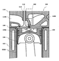
- FIGS. 2 and 3 show details of each cylinder of the diesel engine 100 having two intake valves and two exhaust valves per cylinder.
- a piston 106 to which a piston ring 104 composed of a compression ring and an oil ring is attached is inserted into a thin cylindrical cylinder liner 102A press-fitted into the cylinder block 102 so as to be capable of reciprocating in the axial direction of the cylinder liner 102A. Yes.
- a cavity 106A that forms a part of the combustion chamber is formed concentrically with the piston 106.
- the cavity 106A has, for example, a circular cross section in a plan view, and has a mountain-shaped bottom surface whose center gradually protrudes in the crown surface direction.
- “circular” means not only a perfect circle but also a circular shape in appearance.
- a cylinder head 110 that forms a part of the combustion chamber is fastened to the upper surface of the cylinder block 102 with a cylinder head gasket 108 interposed therebetween.
- the cylinder head 110 is formed with an intake port 110A for introducing intake air into the combustion chamber and an exhaust port 110B for discharging combustion gas from the combustion chamber.
- a valve stem guide 112 is press-fitted into the cylinder head 110 at a position facing the front end openings of the intake port 110A and the exhaust port 110B.
- An intake valve 114 and an exhaust valve 116 are fitted into the valve stem guide 112 so as to be capable of reciprocating in the axial direction.
- the cylinder head 110 is provided with a fuel injection device 460 for injecting fuel toward the combustion chamber at a position facing the center of the combustion chamber, that is, the center of the piston 106, in order to make fuel injection into the combustion chamber uniform.
- the fuel injection device 460 is, for example, an electromagnetic injection valve in which a coil operates in response to a drive signal from an injector driver of the ECU 440 and a needle valve that is biased in the valve closing direction lifts to inject fuel. . For this reason, fuel adjusted to a predetermined pressure is supplied to the fuel injection device 460.
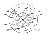
- eight injection holes are formed at equal intervals around the axis of the fuel injection device 460 so as to uniformly inject fuel into the combustion chamber in plan view.
- the eight injection holes of the fuel injection device 460 inject fuel sprays 460A to 460H, respectively.
- the temperature distribution of the cylinder head 110 has a high temperature at the portion sandwiched between the valve shafts of the two exhaust valves 116 when the tip of the fuel injection device 460 is used as a reference (starting point).
- the heat load in this part is higher than in other parts.
- the fuel injection angle ⁇ 1 in the vertical plane of the injection hole for injecting fuel toward the portion where the thermal load of the cylinder head 110 is high is determined from the fuel injection angle ⁇ 0 of the other injection holes. Is also directed to the bottom surface of the cavity 106A.
- the fuel injection angle ⁇ 1 of the injection hole that injects the fuel toward the portion where the thermal load of the cylinder head 110 is high in plan view is set to the fuel injection of the other injection holes. The angle is smaller than ⁇ 0 ( ⁇ 1 ⁇ 0 ).
- the injection hole taking the fuel injection angle ⁇ 1 can be a portion A sandwiched between the valve shafts of the two exhaust valves 116 as shown in FIG.
- the nozzle hole having the fuel injection angle ⁇ 1 is the nozzle hole of the fuel spray 460A in which fuel is injected into the portion A among the fuel sprays 460A to 460H.
- the fuel injection angle ⁇ 1 of the nozzle hole toward the bottom surface of the cavity 106A is an operating state in which the thermal condition is the most severe, specifically, a high load operation of the diesel engine 100, and the top dead center of the piston 106.
- the angle at which the fuel spray does not adhere to the crown surface of the piston 106 is set. In the low load operation or medium load operation of the diesel engine 100, since the absolute amount of fuel injected into the combustion chamber is small, the temperature of the combustion gas does not increase so much and the thermal load on the cylinder head does not increase so much.
- the fuel injection angle ⁇ 1 in the vertical plane of the injection hole for injecting fuel toward the portion where the thermal load of the cylinder head 110 is high is more cavity than the fuel injection angle ⁇ 0 of the other injection holes. Since it faces toward the bottom surface of 106A, less fuel adheres to the crown surface of the piston 106. For this reason, the absolute amount of the air-fuel mixture combusting in the vicinity of the exhaust valve 116 is reduced, and the average heat distribution of the cylinder head 110 is promoted. Therefore, the thermal load on the cylinder head 110 can be reduced while improving combustion.
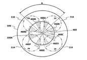
- the fuel injection device 460 is not limited to one having eight injection holes, but may be one that injects fuel sprays 460A to 460F from six injection holes as shown in FIG. In this case, the fuel injection angle in the vertical plane of the injection hole of the fuel spray 460A injected into the portion A where the thermal load of the cylinder head 110 is high is set closer to the bottom surface of the cavity 106A than the fuel injection angle of the other injection holes. Turn.
- the fuel in the vertical plane of the plurality of injection holes for injecting the fuel into the portion A is directed to the bottom surface of the cavity 106A rather than the injection angles of the other injection holes.
- the injection angle in the vertical plane of the nozzle holes for injecting the fuel sprays 460A and 460H is directed toward the bottom surface of the cavity 106A, and in the example shown in FIG. 7, the nozzle holes for injecting the fuel sprays 460A and 460F.
- the injection angle in the vertical plane is directed to the bottom surface of the cavity 106A.
- the number of injection holes and the fuel injection direction of the fuel injection device 460 are not limited to those shown in the figure, and can be any number and injection direction.
- the fuel injection direction of the fuel injection device 400 may not be equally spaced around the axis of the fuel injection device 400.
- the interval between the injection holes that are injected toward a portion with a high thermal load may be set to other injection holes. You may make it expand rather than the space
- this embodiment can be applied not only to the diesel engine 100 but also to a direct injection type gasoline engine that directly injects gasoline into the combustion chamber.
Landscapes
- Engineering & Computer Science (AREA)
- Chemical & Material Sciences (AREA)
- Combustion & Propulsion (AREA)
- Mechanical Engineering (AREA)
- General Engineering & Computer Science (AREA)
- Combustion Methods Of Internal-Combustion Engines (AREA)
Abstract
ピストン冠面のキャビティに複数の噴孔から燃料を噴射する燃料噴射装置において、平面視で、シリンダヘッドの熱負荷が高い部分に向けて燃料を噴射する噴孔の鉛直面内における燃料噴射角度θ1を、他の噴孔の燃料噴射角度θ0よりもキャビティの底面に向ける(θ1<θ0)。ここで、シリンダヘッドの熱負荷が高い部分は、平面視で、燃料噴射装置を基準として、2つの排気弁の弁軸に挟まれた部分である。そして、熱負荷が高い部分で燃焼する燃料の絶対量を減らし、シリンダヘッドの熱負荷を軽減する。
Description
本発明は、燃焼室に燃料を直接噴射する燃料噴射装置、及び、シリンダヘッドの熱負荷を軽減する方法に関する。
ディーゼルエンジンなどの直接噴射式エンジンにおいては、特開2001-115843号公報(特許文献1)に記載されるように、ピストン冠面に陥凹形成されたキャビティに向けて燃料を噴射する構成が採用されている。直接噴射式エンジンでは、燃料噴射角度を水平、即ち、ピストン冠面と平行な方向に近づけると、圧縮行程においてシリンダからキャビティへと流れ込むスキッシュにより燃料と空気との混合が促進され、燃焼が改善することが知られている。
しかしながら、燃料噴射角度を水平に近づけると、燃焼領域がシリンダヘッドの下面に近づき、シリンダヘッドの下面が燃焼熱に晒されることとなる。吸気弁付近のシリンダヘッドは、吸気ポートから吸気が流れ込むことで冷却されるが、排気弁付近のシリンダヘッドは、燃焼ガスが排気ポートに流れ出ることで高温になり易い。従って、排気弁付近のシリンダヘッド、特に、2つの排気弁に挟まれる部分のシリンダヘッドは、他の部分と比べて、熱負荷が大きいという問題があった。
そこで、本発明は、シリンダヘッドの熱負荷を軽減できる、燃料噴射装置及びシリンダヘッドの熱負荷低減方法を提供することを目的とする。
燃料噴射装置の複数の噴孔からピストン冠面のキャビティに燃料を噴射するとき、平面視で、シリンダヘッドの熱負荷が高い部分に向けて燃料を噴射する噴孔の鉛直面内における燃料噴射角度を、他の噴孔の燃料噴射角度よりもキャビティの底面に向ける。
本発明によれば、シリンダヘッドの熱負荷を軽減することができる。
以下、添付された図面を参照し、本発明を実施するための実施形態について詳述する。
図1は、排気中のNOx(窒素酸化物)を浄化するSCRシステムを搭載したディーゼルエンジンの概要を示す。
図1は、排気中のNOx(窒素酸化物)を浄化するSCRシステムを搭載したディーゼルエンジンの概要を示す。
ディーゼルエンジン100の吸気マニフォールド120に接続された吸気管140には、吸気流通方向に沿って、吸気中の埃などを濾過するエアクリーナ160、吸気を過給するターボチャージャ180のコンプレッサ182、コンプレッサ182を通過した吸気を冷却するインタークーラ200、吸気脈動を平滑化する吸気コレクタ220がこの順番で配設されている。
一方、ディーゼルエンジン100の排気マニフォールド240に接続された排気管260には、排気流通方向に沿って、ターボチャージャ180のタービン184、連続再生式ディーゼルパティキュレートフィルタ(Diesel Particulate Filter、以下「DPF」という。)装置280、還元剤前駆体としての尿素水溶液を噴射供給する噴射ノズル300、尿素水溶液から生成されるアンモニアを使用してNOxを選択還元浄化するSCRコンバータ320、SCRコンバータ320を通過したアンモニアを酸化させる酸化触媒コンバータ340がこの順番で配設されている。連続再生式DPF装置280は、少なくともNO(一酸化窒素)をNO2(二酸化窒素)へと酸化させるDOC(Diesel Oxidation Catalyst)コンバータ282と、PM(Particulate Matter)を捕集除去するDPF284と、を有する。なお、DPF284の代わりに、その表面に触媒(活性成分及び添加成分)を担持させたCSF(Catalyzed Soot Filter)を使用することもできる。
還元剤タンク360に貯蔵された尿素水溶液は、ポンプ及び流量制御弁が内蔵された還元剤添加ユニット380を介して、噴射ノズル300に供給される。ここで、還元剤添加ユニット380としては、ポンプが内蔵されたポンプモジュールと、流量制御弁が内蔵されたドージングモジュールと、に2分割されていてもよい。
連続再生式DPF装置280と噴射ノズル300との間に位置する排気管260には、SCRコンバータ320の活性状態を把握するため、排気の温度(排気温度)を測定する温度センサ400が取り付けられている。温度センサ400の出力信号は、コンピュータを内蔵した還元剤添加コントロールユニット(DCU:Dosing Control Unit)420に入力される。また、DCU420は、エンジン運転状態の一例としての回転速度及び負荷を任意の時点で読み込み可能とすべく、CAN(Controller Area Network)などの車載ネットワークを介して、ディーゼルエンジン100を電子制御するエンジンコントロールユニット(ECU:Engine Control Unit)440と通信可能に接続されている。そして、DCU420は、フラッシュROM(Read Only Memory)などの不揮発性メモリに格納された制御プログラムを実行することで、排気温度、回転速度及び負荷に応じて還元剤添加ユニット380のポンプ及び流量制御弁を電子制御する。
ここで、ディーゼルエンジン100の負荷としては、例えば、燃料噴射量、吸気流量、吸気圧力、過給圧力、アクセル操作量など、エンジントルクと密接に関連する状態量を使用することができる。また、ディーゼルエンジン100の回転速度及び負荷は、ECU440から読み込む代わりに、公知のセンサを使用して直接検出するようにしてもよい。
かかる排気浄化装置において、ディーゼルエンジン100の排気は、排気マニフォールド240、ターボチャージャ180のタービン184を経て、連続再生式DPF装置280のDOCコンバータ282に導入される。DOCコンバータ282に導入された排気は、NOがNO2へと酸化されつつDPF284へと流れる。DPF284では、排気中のPMが捕集されると共に、DOCコンバータ282により生成されたNO2を使用してPMが連続的に酸化(焼却)される。
また、エンジン運転状態に応じて噴射ノズル300から噴射供給(添加)された尿素水溶液は、排気熱及び排気中の水蒸気を使用して加水分解され、還元剤として機能するアンモニアへと転化される。このアンモニアは、SCRコンバータ320において排気中のNOxと選択還元反応し、無害なH2O(水)及びN2(窒素)へと浄化されることは知られたことである。このとき、DOCコンバータ282によりNOがNO2へと酸化され、排気中のNOとNO2との比率が選択還元反応に適したものに改善されるため、SCRコンバータ320におけるNOx浄化率を向上させることができる。一方、SCRコンバータ320を通過したアンモニアは、その排気下流に配設された酸化触媒コンバータ340により酸化されるので、アンモニアがそのまま大気中に放出されることを抑制できる。
図2及び図3は、1気筒あたり吸気弁及び排気弁を2つずつ有する、ディーゼルエンジン100の各気筒の詳細を示す。
シリンダブロック102に圧入された薄肉円筒形状のシリンダライナ102Aには、コンプレッションリング及びオイルリングからなるピストンリング104が取り付けられたピストン106が、シリンダライナ102Aの軸方向に往復動可能に嵌挿されている。ピストン106の冠面には、ピストン106と同心に、燃焼室の一部を形成するキャビティ106Aが陥凹形成されている。キャビティ106Aは、例えば、平面視で円形断面をなし、その中央が冠面方向へと徐々に突出した山形形状の底面を有している。ここで、「円形」とは、真円に限らず、見た目で円形をなしていることをいう。
シリンダブロック102に圧入された薄肉円筒形状のシリンダライナ102Aには、コンプレッションリング及びオイルリングからなるピストンリング104が取り付けられたピストン106が、シリンダライナ102Aの軸方向に往復動可能に嵌挿されている。ピストン106の冠面には、ピストン106と同心に、燃焼室の一部を形成するキャビティ106Aが陥凹形成されている。キャビティ106Aは、例えば、平面視で円形断面をなし、その中央が冠面方向へと徐々に突出した山形形状の底面を有している。ここで、「円形」とは、真円に限らず、見た目で円形をなしていることをいう。
また、シリンダブロック102の上面には、シリンダヘッドガスケット108を介在させて、燃焼室の一部を形成するシリンダヘッド110が締結されている。シリンダヘッド110には、吸気を燃焼室に導入するための吸気ポート110Aと、燃焼ガスを燃焼室から排出するための排気ポート110Bと、が夫々形成されている。さらに、シリンダヘッド110には、吸気ポート110A及び排気ポート110Bの先端開口を臨む位置にバルブステムガイド112が圧入されている。そして、バルブステムガイド112には、吸気弁114及び排気弁116が軸方向に往復動可能に嵌挿されている。
シリンダヘッド110には、燃焼室への燃料噴射を均一化すべく、燃焼室の中央、即ち、ピストン106の中央を臨む位置に、燃焼室に向けて燃料を噴射する燃料噴射装置460が配設されている。燃料噴射装置460は、例えば、ECU440のインジェクタドライバからの駆動信号に応じてコイルが作動し、閉弁方向に付勢されているニードルバルブがリフトして燃料を噴射する電磁式の噴射弁である。このため、燃料噴射装置460には、所定圧力に調圧された燃料が供給されている。燃料噴射装置460の先端には、平面視で燃焼室に均一に燃料を噴射すべく、燃料噴射装置460の軸線回りに8つの噴孔が等間隔で開設されている。そして、燃料噴射装置460の8つの噴孔は、燃料噴霧460A~460Hを夫々噴射する。
ここで、前述したように、燃料噴射角度を水平、即ち、ピストン106の冠面と平行な方向に近づけると、圧縮行程においてシリンダからキャビティ106Aへと流れ込むスキッシュにより燃料と空気との混合が促進され、燃焼が改善する。しかし、吸気弁114付近のシリンダヘッド110は、吸気ポート110Aから吸気が流れ込むことで冷却されるが、排気弁116付近のシリンダヘッド110は、燃料ガスが排気ポート110Bに流れ出ることで高温になり易い。このため、シリンダヘッド110の温度分布は、図4に示すように、燃料噴射装置460の先端を基準(起点)とすると、2つの排気弁116の弁軸に挟まれた部分が高温になり、この部分の熱負荷が他の部分に比べて高くなる。
そこで、図2に示すように、シリンダヘッド110の熱負荷が高い部分に向けて燃料を噴射する噴孔の鉛直面内における燃料噴射角度θ1を、他の噴孔の燃料噴射角度θ0よりもキャビティ106Aの底面に向けるようにする。要するに、燃料噴射装置460の複数の噴孔のうち、平面視でシリンダヘッド110の熱負荷が高い部分に向けて燃料を噴射する噴孔の燃料噴射角度θ1を、他の噴孔の燃料噴射角度θ0よりも小さくする(θ1<θ0)。
燃料噴射角度θ1をとる噴孔は、具体的には、図3に示すように、2つの排気弁116の弁軸に挟まれた部分Aとすることができる。図3に示す一例では、燃料噴射角度θ1をとる噴孔は、燃料噴霧460A~460Hのうち、部分Aに燃料が噴射される燃料噴霧460Aの噴孔となる。また、キャビティ106Aの底面に向けた噴孔の燃料噴射角度θ1は、熱的条件が最も厳しくなる運転状態、具体的には、ディーゼルエンジン100の高負荷運転、かつ、ピストン106の上死点において、ピストン106の冠面に燃料噴霧が付着しない角度とする。なお、ディーゼルエンジン100の低負荷運転又は中負荷運転においては、燃焼室に噴射される燃料の絶対量が少ないため、燃焼ガスの温度がそれほど上昇せず、シリンダヘッドの熱負荷がさほど高くならない。
このようにすれば、シリンダヘッド110の熱負荷が高い部分へと向けて燃料を噴射する噴孔の鉛直面内における燃料噴射角度θ1は、他の噴孔の燃料噴射角度θ0よりもキャビティ106Aの底面に向かっているので、ピストン106の冠面に付着する燃料が少なくなる。このため、排気弁116付近で燃焼する混合気の絶対量が減り、シリンダヘッド110の熱分布の平均化が促進される。よって、燃焼を改善しつつ、シリンダヘッド110の熱負荷を軽減することができる。
燃料噴射装置460としては、8つの噴孔を有するものに限らず、図5に示すように、6つの噴孔から燃料噴霧460A~460Fを噴射するものであってもよい。この場合には、シリンダヘッド110の熱負荷が高い部分Aに噴射される燃料噴霧460Aの噴孔の鉛直面内の燃料噴射角度を、他の噴孔の燃料噴射角度よりもキャビティ106Aの底面に向ける。
また、シリンダヘッド110の熱負荷が高い部分Aに複数の燃料噴霧が噴射される場合、図6及び図7に示すように、部分Aに燃料を噴射する複数の噴孔の鉛直面内の燃料噴射角度を、他の噴孔の噴射角度よりもキャビティ106Aの底面に向ける。図6に示す一例では、燃料噴霧460A及び460Hを噴射する噴孔の鉛直面内の噴射角度をキャビティ106Aの底面に向け、図7に示す一例では、燃料噴霧460A及び460Fを噴射する噴孔の鉛直面内の噴射角度をキャビティ106Aの底面に向ける。
なお、燃料噴射装置460の噴孔数及び燃料噴射方向は、図示のものに限らず、任意の数及び噴射方向とすることができる。また、燃料噴射装置400の燃料噴射方向は、燃料噴射装置400の軸線回りに等間隔でなくてもよく、例えば、熱負荷が高い部分に向けて噴射する噴孔の間隔を、他の噴孔の間隔より広げるようにしてもよい。
さらに、本実施形態は、ディーゼルエンジン100に限らず、ガソリンを燃焼室に直接噴射する直接噴射式のガソリンエンジンにも適用することができる。
100 ディーゼルエンジン
106 ピストン
106A キャビティ
110 シリンダヘッド
116 排気弁
460 燃料噴射装置
106 ピストン
106A キャビティ
110 シリンダヘッド
116 排気弁
460 燃料噴射装置
Claims (9)
- ピストン冠面のキャビティに複数の噴孔から燃料を噴射する燃料噴射装置において、
平面視で、シリンダヘッドの熱負荷が高い部分に向けて燃料を噴射する噴孔の鉛直面内における燃料噴射角度を、他の噴孔の燃料噴射角度よりも前記キャビティの底面に向けた、
ことを特徴とする燃料噴射装置。 - 前記シリンダヘッドの熱負荷が高い部分は、平面視で、2つの排気弁の弁軸に挟まれた部分である、
ことを特徴とする請求項1に記載の燃料噴射装置。 - 前記キャビティの底面に向けた噴孔の鉛直面内における燃料噴射角度は、高負荷運転、かつ、前記ピストンの上死点において、前記ピストン冠面に燃料が付着しない角度である、
ことを特徴とする請求項1に記載の燃料噴射装置。 - 前記燃料噴射装置は、前記シリンダヘッドの燃焼室の中央に配置された、
ことを特徴とする請求項1に記載の燃料噴射装置。 - 前記燃料噴射装置の噴孔は、前記燃料噴射装置の軸線回りに等間隔で開設されている、
ことを特徴とする請求項1に記載の燃料噴射装置。 - 前記燃料噴射弁は、ディーゼルエンジンのシリンダヘッドに取り付けられた、
ことを特徴とする請求項1に記載の燃料噴射装置。 - 燃料噴射装置の複数の噴孔からピストン冠面のキャビティに燃料を噴射するとき、平面視で、シリンダヘッドの熱負荷が高い部分に向けて燃料を噴射する噴孔の鉛直面内における燃料噴射角度を、他の噴孔の燃料噴射角度よりも前記キャビティの底面に向け、熱負荷が高い部分で燃焼する燃料の絶対量を減らした、
ことを特徴とするシリンダヘッドの熱負荷軽減方法。 - 前記シリンダヘッドの熱負荷が高い部分は、平面視で、2つの排気弁の弁軸に挟まれた部分である、
ことを特徴とする請求項7に記載のシリンダヘッドの熱負荷軽減方法。 - 前記キャビティの底面に向けた噴孔の鉛直面内における燃料噴射角度は、高負荷運転、かつ、前記ピストンの上死点において、前記ピストン冠面に燃料が付着しない角度である、
ことを特徴とする請求項7に記載のシリンダヘッドの熱負荷軽減方法。
Priority Applications (1)
| Application Number | Priority Date | Filing Date | Title |
|---|---|---|---|
| PCT/JP2012/082068 WO2014091556A1 (ja) | 2012-12-11 | 2012-12-11 | 燃料噴射装置及びシリンダヘッドの熱負荷軽減方法 |
Applications Claiming Priority (1)
| Application Number | Priority Date | Filing Date | Title |
|---|---|---|---|
| PCT/JP2012/082068 WO2014091556A1 (ja) | 2012-12-11 | 2012-12-11 | 燃料噴射装置及びシリンダヘッドの熱負荷軽減方法 |
Publications (1)
| Publication Number | Publication Date |
|---|---|
| WO2014091556A1 true WO2014091556A1 (ja) | 2014-06-19 |
Family
ID=50933882
Family Applications (1)
| Application Number | Title | Priority Date | Filing Date |
|---|---|---|---|
| PCT/JP2012/082068 Ceased WO2014091556A1 (ja) | 2012-12-11 | 2012-12-11 | 燃料噴射装置及びシリンダヘッドの熱負荷軽減方法 |
Country Status (1)
| Country | Link |
|---|---|
| WO (1) | WO2014091556A1 (ja) |
Cited By (1)
| Publication number | Priority date | Publication date | Assignee | Title |
|---|---|---|---|---|
| WO2017018193A1 (ja) * | 2015-07-24 | 2017-02-02 | 株式会社デンソー | 燃料噴射装置 |
Citations (1)
| Publication number | Priority date | Publication date | Assignee | Title |
|---|---|---|---|---|
| JP2008038650A (ja) * | 2006-08-02 | 2008-02-21 | Honda Motor Co Ltd | 燃料直噴ディーゼルエンジン |
-
2012
- 2012-12-11 WO PCT/JP2012/082068 patent/WO2014091556A1/ja not_active Ceased
Patent Citations (1)
| Publication number | Priority date | Publication date | Assignee | Title |
|---|---|---|---|---|
| JP2008038650A (ja) * | 2006-08-02 | 2008-02-21 | Honda Motor Co Ltd | 燃料直噴ディーゼルエンジン |
Cited By (2)
| Publication number | Priority date | Publication date | Assignee | Title |
|---|---|---|---|---|
| WO2017018193A1 (ja) * | 2015-07-24 | 2017-02-02 | 株式会社デンソー | 燃料噴射装置 |
| JP2017025835A (ja) * | 2015-07-24 | 2017-02-02 | 株式会社デンソー | 燃料噴射装置 |
Similar Documents
| Publication | Publication Date | Title |
|---|---|---|
| US9689290B2 (en) | Reductant mixing system for an exhaust gas after-treatment device | |
| EP1939422B1 (en) | Exhaust gas purifier for diesel engine | |
| US8176729B2 (en) | Perturbation control strategy for low-temperature urea SCR NOx reduction | |
| JP2008303821A (ja) | 内燃機関の排気浄化装置 | |
| US20090077954A1 (en) | Continuously regenerating particulate filter for internal combustion engine | |
| JP5013121B2 (ja) | 排気浄化装置 | |
| JP2013142363A (ja) | ディーゼルエンジンの排気ガス浄化装置 | |
| JP2010019239A (ja) | 排気浄化装置 | |
| EP2072774A1 (en) | Compression ignition engine comprising a three way catalyst device | |
| JPWO2011101898A1 (ja) | 内燃機関の排気浄化装置 | |
| US9976464B1 (en) | Reductant spray and exhaust gas flow guide and deflector | |
| EP3369898A1 (en) | After treatment system (ats) for a sparking ignition engine | |
| JP2016211486A (ja) | 排出ガス浄化システム | |
| US20110271657A1 (en) | Control system and method for improved efficiency of particulate matter filter regeneration | |
| JP2018131997A (ja) | 排気ガス浄化装置 | |
| JP4784761B2 (ja) | 排気浄化装置 | |
| US10337383B2 (en) | Selective catalyst reduction efficiency determination | |
| WO2014091556A1 (ja) | 燃料噴射装置及びシリンダヘッドの熱負荷軽減方法 | |
| US8480962B2 (en) | Exhaust gas purification apparatus for engine | |
| JP7647591B2 (ja) | 排気浄化システム | |
| WO2014125870A1 (ja) | エンジンの排気浄化装置 | |
| JP4375311B2 (ja) | 内燃機関の排気浄化システム | |
| JP4844766B2 (ja) | 排気浄化装置 | |
| US20190063292A1 (en) | Variable-position mixer for an exhaust gas after-treatment system | |
| JP2011149402A (ja) | 車両の発進補助システム |
Legal Events
| Date | Code | Title | Description |
|---|---|---|---|
| 121 | Ep: the epo has been informed by wipo that ep was designated in this application |
Ref document number: 12889987 Country of ref document: EP Kind code of ref document: A1 |
|
| NENP | Non-entry into the national phase |
Ref country code: DE |
|
| 122 | Ep: pct application non-entry in european phase |
Ref document number: 12889987 Country of ref document: EP Kind code of ref document: A1 |