WO2014087963A1 - 多原色表示装置 - Google Patents
多原色表示装置 Download PDFInfo
- Publication number
- WO2014087963A1 WO2014087963A1 PCT/JP2013/082337 JP2013082337W WO2014087963A1 WO 2014087963 A1 WO2014087963 A1 WO 2014087963A1 JP 2013082337 W JP2013082337 W JP 2013082337W WO 2014087963 A1 WO2014087963 A1 WO 2014087963A1
- Authority
- WO
- WIPO (PCT)
- Prior art keywords
- pixel
- sub
- pixels
- primary color
- virtual
- Prior art date
- Legal status (The legal status is an assumption and is not a legal conclusion. Google has not performed a legal analysis and makes no representation as to the accuracy of the status listed.)
- Ceased
Links
Images














Classifications
-
- G—PHYSICS
- G09—EDUCATION; CRYPTOGRAPHY; DISPLAY; ADVERTISING; SEALS
- G09G—ARRANGEMENTS OR CIRCUITS FOR CONTROL OF INDICATING DEVICES USING STATIC MEANS TO PRESENT VARIABLE INFORMATION
- G09G3/00—Control arrangements or circuits, of interest only in connection with visual indicators other than cathode-ray tubes
- G09G3/20—Control arrangements or circuits, of interest only in connection with visual indicators other than cathode-ray tubes for presentation of an assembly of a number of characters, e.g. a page, by composing the assembly by combination of individual elements arranged in a matrix no fixed position being assigned to or needed to be assigned to the individual characters or partial characters
- G09G3/34—Control arrangements or circuits, of interest only in connection with visual indicators other than cathode-ray tubes for presentation of an assembly of a number of characters, e.g. a page, by composing the assembly by combination of individual elements arranged in a matrix no fixed position being assigned to or needed to be assigned to the individual characters or partial characters by control of light from an independent source
- G09G3/36—Control arrangements or circuits, of interest only in connection with visual indicators other than cathode-ray tubes for presentation of an assembly of a number of characters, e.g. a page, by composing the assembly by combination of individual elements arranged in a matrix no fixed position being assigned to or needed to be assigned to the individual characters or partial characters by control of light from an independent source using liquid crystals
- G09G3/3611—Control of matrices with row and column drivers
-
- G—PHYSICS
- G09—EDUCATION; CRYPTOGRAPHY; DISPLAY; ADVERTISING; SEALS
- G09G—ARRANGEMENTS OR CIRCUITS FOR CONTROL OF INDICATING DEVICES USING STATIC MEANS TO PRESENT VARIABLE INFORMATION
- G09G3/00—Control arrangements or circuits, of interest only in connection with visual indicators other than cathode-ray tubes
- G09G3/20—Control arrangements or circuits, of interest only in connection with visual indicators other than cathode-ray tubes for presentation of an assembly of a number of characters, e.g. a page, by composing the assembly by combination of individual elements arranged in a matrix no fixed position being assigned to or needed to be assigned to the individual characters or partial characters
- G09G3/2003—Display of colours
-
- G—PHYSICS
- G09—EDUCATION; CRYPTOGRAPHY; DISPLAY; ADVERTISING; SEALS
- G09G—ARRANGEMENTS OR CIRCUITS FOR CONTROL OF INDICATING DEVICES USING STATIC MEANS TO PRESENT VARIABLE INFORMATION
- G09G2300/00—Aspects of the constitution of display devices
- G09G2300/04—Structural and physical details of display devices
- G09G2300/0439—Pixel structures
- G09G2300/0452—Details of colour pixel setup, e.g. pixel composed of a red, a blue and two green components
-
- G—PHYSICS
- G09—EDUCATION; CRYPTOGRAPHY; DISPLAY; ADVERTISING; SEALS
- G09G—ARRANGEMENTS OR CIRCUITS FOR CONTROL OF INDICATING DEVICES USING STATIC MEANS TO PRESENT VARIABLE INFORMATION
- G09G2340/00—Aspects of display data processing
- G09G2340/06—Colour space transformation
Definitions
- the present invention relates to a display device, and more particularly to a multi-primary color display device that performs display using four or more primary colors.
- one pixel is constituted by three sub-pixels that display red, green, and blue, which are the three primary colors of light, thereby enabling color display.
- the conventional display device has a problem that a displayable color range (referred to as a “color reproduction range”) is narrow.
- a displayable color range referred to as a “color reproduction range”
- it is impossible to display a part of the object color the colors of various objects existing in nature; see Non-Patent Document 1). Therefore, in order to widen the color reproduction range of the display device, a method of increasing the number of primary colors used for display has been proposed.
- Patent Document 1 discloses a display device that performs display using six primary colors.
- Patent Document 1 also discloses a display device that performs display using four primary colors and a display device that performs display using five primary colors.
- An example of a display device that performs display using the six primary colors is shown in FIG.
- one pixel P is configured by the red sub-pixel R, the green sub-pixel G, the blue sub-pixel B, the cyan sub-pixel C, the magenta sub-pixel M, and the yellow sub-pixel Ye.
- color display is performed by mixing the six primary colors red, green, blue, cyan, magenta, and yellow displayed by the six sub-pixels.
- a display device that performs display using four or more primary colors is referred to as a “multi-primary color display device”, and a display device that performs display using three primary colors (that is, a conventional general) is referred to as “three primary colors”. It is referred to as a “display device”.
- the present invention has been made in view of the above problems, and an object of the present invention is to display multi-primary colors capable of displaying an image with the same or higher resolution without reducing the sub-pixel size as compared with the three primary color display device. To provide an apparatus.
- a multi-primary color display device has a plurality of pixels arranged in a matrix including a plurality of rows and a plurality of columns, and each of the plurality of pixels displays at least four different primary colors.
- a multi-primary color display device including a plurality of sub-pixels including one sub-pixel, wherein each of the plurality of sub-pixels configuring each pixel is composed of n (n is a plurality of sub-pixels). 2 or more virtual pixels), each of the n virtual pixels can be displayed as a minimum color display unit, and the two or more sub-pixels constituting each of the n virtual pixels can be displayed.
- the pixels include sub-pixels common to other virtual pixels, and when a line having a width corresponding to the n virtual pixels is displayed, the pixels are located at both ends in the width direction of the lines and are the same as each other
- the first luminance subpixel of the first and second sub-pixels for displaying that primaries, the original lower than the luminance, the luminance of the second sub-pixel is higher than original luminance.
- the line having a width corresponding to the n virtual pixels is a white line, and when the white line is displayed in a black background, the luminance of the first sub-pixel has a minimum gradation.
- the luminance of the second sub-pixel is equal to the sum of the original luminance of the first sub-pixel and the original luminance of the second sub-pixel.
- the second sub-pixels are alternately positioned at one end and the other end in the width direction of the line along a direction in which the line extends.
- the multi-primary color display device having the above-described configuration includes a signal conversion circuit that converts an input image signal corresponding to three primary colors into a multi-primary color image signal corresponding to four or more primary colors.
- the signal conversion circuit includes a detection unit that detects that the line having a width corresponding to the n virtual pixels is displayed.
- the signal conversion circuit includes a low-frequency multi-primary color signal generation unit that generates a low-frequency multi-primary color signal that is a signal in which low-frequency components of the input image signal are multi-primary based on the input image signal.
- a high-frequency luminance signal generating unit that generates a high-frequency luminance signal that is a signal obtained by luminance-converting a high-frequency component of the input image signal based on the input image signal; and the low-frequency multi-primary color signal generating unit
- a rendering processing unit that performs rendering processing on the n virtual pixels based on a low-frequency multi-primary color signal and a high-frequency luminance signal generated by the high-frequency luminance signal generation unit.
- the low-frequency multi-primary color signal generation unit extracts a low-frequency component extraction unit that extracts a low-frequency component from the input image signal, and a low-frequency component of the input image signal extracted by the low-frequency component extraction unit.
- a multi-primary color conversion unit that converts multi-primary colors.
- the high frequency luminance signal generation unit generates a luminance signal by converting luminance of an input image signal, and converts a high frequency component of the luminance signal generated by the luminance conversion unit to a high frequency luminance.
- a high-frequency component extracting unit that extracts the signal as a signal.
- a multi-primary color display device having the above-described configuration includes a multi-primary color display panel having the plurality of sub-pixels in each of the plurality of pixels.
- the plurality of rows are substantially parallel to a horizontal direction of a display surface, and within each of the plurality of pixels, the plurality of sub-pixels are arranged in one row and multiple columns, and the line is , Extending in the column direction.
- the plurality of sub-pixels include a red sub-pixel that displays red, a green sub-pixel that displays green, and a blue sub-pixel that displays blue.
- the plurality of subpixels include at least one of a cyan subpixel that displays cyan, a magenta subpixel that displays magenta, a yellow subpixel that displays yellow, and a white subpixel that displays white. .
- the plurality of sub-pixels includes a further red sub-pixel that displays red.
- the multi-primary color display device having the above-described configuration is a liquid crystal display device.
- the embodiment of the present invention it is possible to provide a multi-primary color display device capable of displaying an image having the same or higher resolution without reducing the sub-pixel size as compared with the three primary color display device.
- FIG. 1 is a block diagram schematically showing a liquid crystal display device (multi-primary color display device) 100 according to an embodiment of the present invention.
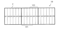
- 3 is a diagram illustrating an example of sub-pixel arrangement of a multi-primary color display panel 10 included in the liquid crystal display device 100.
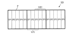
- FIG. 3 is a diagram illustrating an example of sub-pixel arrangement of a multi-primary color display panel 10 included in the liquid crystal display device 100.
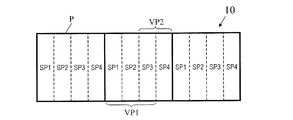
- FIG. 3 is a diagram illustrating an example of sub-pixel arrangement of a multi-primary color display panel 10 included in the liquid crystal display device 100.
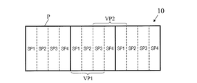
- FIG. It is a figure which shows the example of the allocation pattern of the some sub pixel to a some virtual pixel.
- FIG. 3 is a block diagram illustrating an example of a specific configuration of a signal conversion circuit 20 included in the liquid crystal display device 100.
- FIG. A table showing a rendering result in consideration of a low-frequency component, a high-frequency component, a pixel value, a weight of each primary color in the first virtual pixel, a weight of each primary color in the second virtual pixel, and a virtual pixel for a part of a certain pixel row is there.
- a table showing pixel values and rendering results when the weight W (1, m) of the m-th primary color in the first virtual pixel and the weight W (2, m) of the m-th primary color in the second virtual pixel are set to certain values. is there.
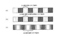
- FIG. 15 schematically show a part of a certain pixel row represented by the rendering result shown in FIG. 15 on the input side, input side (but after multi-primary color conversion) and output side.
- FIG. For a part of a certain pixel row, the low-frequency component, the high-frequency component, the pixel value, the weight of each primary color in the first virtual pixel, the weight of each primary color in the second virtual pixel, the weight of each primary color in the third virtual pixel, and the virtual It is a table
- the weight W (1, m) of the mth primary color in the first virtual pixel, the weight W (2, m) of the mth primary color in the second virtual pixel, and the weight W (3, m) of the mth primary color in the third virtual pixel It is a table
- (A), (b) and (c) schematically show a part of a certain pixel row represented by the rendering result shown in FIG. 18 on the input side, input side (but after multi-primary color conversion) and output side.
- FIG. It is a figure which shows the example of the reduced display using a rendering process. It is a figure which shows the example of the reduced display using a rendering process.
- FIG. 3 is a diagram illustrating a pixel structure (sub-pixel arrangement) in Example 1.
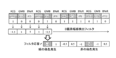
- Example 1 it is a figure which shows the filter response r at the time of using the filter of [-1? 1? 1? -1] as a filter which detects a 2 pixel width line.
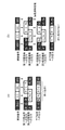
- FIG. 3 is a diagram illustrating a relationship among a luminance signal, outputs to a plurality of virtual pixels, and final outputs to each sub-pixel in Example 1, and (a) does not perform processing for suppressing false colors. (B) shows a case where processing for suppressing false colors is performed.
- 6 is a diagram illustrating a pixel structure (sub-pixel arrangement) in Embodiment 2.
- FIG. In Example 2 it is a figure which shows the filter response r at the time of using the filter of [-1? 1? 1?
- FIG. 9 is a diagram illustrating a relationship among a luminance signal, outputs to a plurality of virtual pixels, and final outputs to each sub-pixel in Example 2, and (a) does not perform processing for suppressing false colors. (B) shows a case where processing for suppressing false colors is performed.
- 10 is a diagram illustrating a pixel structure (sub-pixel arrangement) in Example 3.
- FIG. 9 is a diagram illustrating a relationship among a luminance signal, outputs to a plurality of virtual pixels, and final outputs to each sub-pixel in Example 2, and (a) does not perform processing for suppressing false colors. (B) shows a case where processing for suppressing false colors is performed.
- 10 is a diagram illustrating a pixel structure (sub-pixel arrangement) in Example 3.
- FIG. 10 is a diagram illustrating a relationship between a luminance signal, an output to a plurality of virtual pixels, and an output to each final sub-pixel in Example 3, and (a) does not perform a process of suppressing false colors.
- B shows a case where processing for suppressing false colors is performed. It is a figure which shows the relationship between the luminance signal in Example 4, the output to a some virtual pixel, and the final output to each sub pixel. It is a figure which shows typically the conventional display apparatus 800 which displays using six primary colors.
- liquid crystal display device is illustrated below, this invention is not limited to a liquid crystal display device, It uses suitably also for other display devices, such as an organic electroluminescent display device.
- FIG. 1 shows a liquid crystal display device 100 according to this embodiment.
- the liquid crystal display device 100 includes a multi-primary color display panel 10 and a signal conversion circuit 20, and is a multi-primary color display device that performs display using four or more primary colors.
- the multi-primary color display panel 10 has a plurality of pixels arranged in a matrix including a plurality of rows and a plurality of columns.
- Each of the plurality of pixels includes a plurality of sub-pixels.
- the plurality of sub-pixels constituting each pixel include at least four sub-pixels that display different primary colors.
- FIG. 2 shows an example of a specific pixel structure (sub-pixel arrangement) of the multi-primary color display panel 10.
- each of the plurality of pixels P arranged in a matrix is composed of six sub-pixels SP1 to SP6.
- the six subpixels SP1 to SP6 are arranged in one row and six columns.
- the six subpixels SP1 to SP6 display, for example, a red subpixel R that displays red, a green subpixel G that displays green, a blue subpixel B that displays blue, a cyan subpixel C that displays cyan, and magenta.
- a magenta sub-pixel M and a yellow sub-pixel Ye displaying yellow.
- the pixel structure of the multi-primary color display panel 10 is not limited to the example shown in FIG. 3 and 4 show other examples of the pixel structure of the multi-primary color panel 10.
- each of the plurality of pixels P arranged in a matrix is composed of five sub-pixels SP1 to SP5.
- the five subpixels SP1 to SP5 are arranged in one row and five columns.
- the five subpixels SP1 to SP5 are, for example, a red subpixel R, a green subpixel G, and a blue subpixel B, and any two of a cyan subpixel C, a magenta subpixel M, and a yellow subpixel Ye.
- each of the plurality of pixels P arranged in a matrix is composed of four sub-pixels SP1 to SP4.
- the four subpixels SP1 to SP4 are arranged in one row and four columns.
- the four subpixels SP1 to SP4 are, for example, a red subpixel R, a green subpixel G, and a blue subpixel B, and any one of a cyan subpixel C, a magenta subpixel M, and a yellow subpixel Ye.
- the plurality of sub-pixels constituting each pixel P do not necessarily include only sub-pixels that display different colors.
- a further red sub-pixel R that displays red may be provided instead of any of the cyan sub-pixel C, the magenta sub-pixel M, and the yellow sub-pixel Ye. If two red sub-pixels R are provided in one pixel P, bright (high brightness) red can be displayed.
- a white sub-pixel W that displays white may be provided instead of any of the cyan sub-pixel C, the magenta sub-pixel M, and the yellow sub-pixel Ye. When the white sub-pixel W is provided, the display luminance in the entire pixel P can be improved.
- the sub-pixel arrangement in the pixel P is not limited to this.
- a plurality of subpixels may be arranged in a plurality of rows and one column.
- a plurality of sub-pixels exist in each pixel P along that direction. Therefore, from the viewpoint of obtaining the resolution improvement effect in the row direction, it is preferable that a plurality of sub-pixels are arranged in two or more columns in each pixel P.
- a plurality of sub-pixels are preferably arranged in two or more rows in each pixel P. Further, since the resolution of the human eye is lower in the vertical direction than in the horizontal direction, it is preferable to improve at least the resolution in the horizontal direction. Further, typically, the row direction (that is, a plurality of pixels P is used). The plurality of configured lines) is substantially parallel to the horizontal direction of the display surface. Therefore, it can be said that in general applications, it is preferable that a plurality of sub-pixels are arranged in one row and a plurality of columns in each pixel P. In the following description, a case where pixel rows are substantially parallel to the horizontal direction of the display surface and a plurality of sub-pixels are arranged in one row and multiple columns in each pixel P will be described as an example unless otherwise specified.
- the signal conversion circuit 20 refers to an input image signal (three primary color image signals) corresponding to three primary colors (RGB) as an image signal corresponding to four or more primary colors (“multi-primary color image signal”). .).
- the multi-primary color image signal output from the signal conversion circuit 20 is input to the multi-primary color display panel 10, and color display using four or more primary colors is performed.
- a specific configuration of the signal conversion circuit 20 will be described in detail later.
- the total number of the plurality of pixels P included in the multi-primary color display panel 10 is referred to as “panel resolution”.
- the panel resolution when a plurality of pixels P are arranged in the row direction and A in the column direction is expressed as “A ⁇ B”.
- the minimum display unit of the input image is also referred to as “pixel” for the sake of convenience, and the total number of pixels of the input image is referred to as “resolution of the input image”.
- the resolution of the input image composed of A pixels in the row direction and B pixels in the column direction is expressed as “A ⁇ B”.
- a plurality of sub-pixels constituting each pixel P are distributed to a plurality of virtual pixels (hereinafter referred to as “virtual pixels”), and each of the plurality of virtual pixels is minimized.
- virtual pixels a plurality of virtual pixels
- FIG. 5, FIG. 6 and FIG. 7 show examples of a distribution pattern of a plurality of sub-pixels to a plurality of virtual pixels.
- the six subpixels SP1 to SP6 constituting each pixel P are distributed to two virtual pixels (first and second virtual pixels) VP1 and VP2.
- the first virtual pixel VP1 is composed of four subpixels SP1, SP2, SP3 and SP4 among the six subpixels SP1 to SP6.
- the second virtual pixel VP2 includes three subpixels SP4, SP5, and SP6.
- the sub-pixel SP4 located fourth from the left side in the pixel P constitutes both the first virtual pixel VP1 and the second virtual pixel VP2. That is, the first virtual pixel VP1 and the second virtual pixel VP2 include a common subpixel SP4 and share the subpixel SP4.
- the five subpixels SP1 to SP5 constituting each pixel P are distributed to two virtual pixels (first and second virtual pixels) VP1 and VP2.
- the first virtual pixel VP1 is composed of three subpixels SP1, SP2 and SP3 among the five subpixels SP1 to SP5.
- the second virtual pixel VP2 includes three subpixels SP3, SP4, and SP5.
- the sub-pixel SP3 located in the center in the pixel P constitutes both the first virtual pixel VP1 and the second virtual pixel VP2. That is, the first virtual pixel VP1 and the second virtual pixel VP2 include a common subpixel SP3 and share the subpixel SP3.
- the four subpixels SP1 to SP4 constituting each pixel P are distributed to two virtual pixels (first and second virtual pixels) VP1 and VP2.
- the first virtual pixel VP1 is composed of three subpixels SP1, SP2 and SP3 among the four subpixels SP1 to SP4.
- the second virtual pixel VP2 is composed of two subpixels SP3 and SP4.
- the sub-pixel SP3 located third from the left in the pixel P constitutes both the first virtual pixel VP1 and the second virtual pixel VP2. That is, the two virtual pixels VP1 and VP2 include a common subpixel SP3 and share the subpixel SP3.
- the number of virtual pixels is 2, but the number of virtual pixels is not limited to 2, and may be 3 or more.
- the plurality of sub-pixels constituting the pixel P are distributed to n (n is an integer of 2 or more) virtual pixels.
- FIG. 8 shows another example of the distribution pattern.
- the six subpixels SP1 to SP6 constituting each pixel P are distributed to three virtual pixels (first, second and third virtual pixels) VP1, VP2 and VP3.
- the first virtual pixel VP1 is composed of three subpixels SP1, SP2 and SP3 among the six subpixels SP1 to SP6.
- the second virtual pixel VP2 includes three subpixels SP3, SP4, and SP5.
- the third virtual pixel VP3 is composed of two subpixels SP5 and SP6.
- the sub-pixel SP3 located third from the left in the pixel P constitutes both the first virtual pixel VP1 and the second virtual pixel VP2.
- the first virtual pixel VP1 and the second virtual pixel VP2 include a common subpixel SP3 and share the subpixel SP3.
- the sub pixel SP5 located fifth from the left side in the pixel P constitutes both the second virtual pixel VP2 and the third virtual pixel VP3.
- the second virtual pixel VP2 and the third virtual pixel VP3 include a common subpixel SP5 and share the subpixel SP5.
- each of the plurality of virtual pixels is constituted by two or more sub-pixels that are continuous in one pixel P.
- such distribution is performed. It is not limited to patterns. 9 to 12 show other examples of the distribution pattern.
- the plurality of subpixels SP1 to SP4 are distributed to two virtual pixels VP1 and VP2, and in the distribution pattern shown in FIG. 10, the plurality of subpixels SP1 to SP5 are two virtual pixels. The pixels are distributed to the pixels VP1 and VP2.
- the plurality of subpixels SP1 to SP6 are distributed to two virtual pixels VP1 and VP2, and in the distribution pattern shown in FIG. 12, there are three subpixels SP1 to SP6. To the virtual pixels VP1, VP2, and VP3.
- the first virtual pixel VP1 of the two virtual pixels VP1 and VP2 shown in the vicinity of the center in FIG. 9 is composed of three subpixels SP1, SP2 and SP3 of the center pixel P.
- the second virtual pixel VP2 includes two subpixels SP3 and SP4 of the central pixel P and one subpixel SP1 of the right pixel P.
- the first virtual pixel VP1 shares the second virtual pixel VP2 with the subpixel SP3 located third in the pixel P from the left side.
- the second virtual pixel VP2 is a subpixel SP1 located on the leftmost side in the pixel P, which is another first virtual pixel (a virtual pixel constituted by three subpixels SP1, SP2 and SP3 of the right pixel P). Share with VP1.
- the first virtual pixel VP1 of the two virtual pixels VP1 and VP2 shown in the vicinity of the center in FIG. 10 is composed of three sub-pixels SP1, SP2, and SP3 of the center pixel P.
- the second virtual pixel VP2 includes three subpixels SP3, SP4, and SP5 of the center pixel P and one subpixel SP1 of the right pixel P.
- the first virtual pixel VP1 shares the second virtual pixel VP2 with the subpixel SP3 located third in the pixel P from the left side.
- the second virtual pixel VP2 is a subpixel SP1 located on the leftmost side in the pixel P, which is another first virtual pixel (a virtual pixel constituted by three subpixels SP1, SP2 and SP3 of the right pixel P). Share with VP1.
- the first virtual pixel VP1 of the two virtual pixels VP1 and VP2 shown in the vicinity of the center in FIG. 11 includes four subpixels SP1, SP2, SP3, and SP4 of the center pixel P.
- the second virtual pixel VP2 includes three subpixels SP4, SP5, and SP6 of the central pixel P and one subpixel SP1 of the right pixel P.
- the first virtual pixel VP1 shares the second virtual pixel VP2 with the subpixel SP4 located fourth in the pixel P from the left side.
- the second virtual pixel VP2 is a subpixel SP1 located on the leftmost side in the pixel P.
- the second virtual pixel VP2 is a virtual pixel constituted by another first virtual pixel (four subpixels SP1, SP2, SP3 and SP4 of the right pixel P). Pixel) Shared with VP1.
- the first virtual pixel VP1 among the three virtual pixels VP1, VP2, and VP3 shown in the vicinity of the center in FIG. 12 is composed of three sub-pixels SP1, SP2, and SP3 of the center pixel P.
- the second virtual pixel VP2 includes three subpixels SP3, SP4, and SP5 of the central pixel P.
- the third virtual pixel VP3 includes two subpixels SP5 and SP6 of the central pixel P, and This is composed of one sub-pixel SP1 of the right pixel P.
- the first virtual pixel VP1 shares the second virtual pixel VP2 with the subpixel SP3 located third in the pixel P from the left side.
- the second virtual pixel VP2 shares the third virtual pixel VP3 with the sub-pixel SP5 that is located fifth in the pixel P from the left side.
- the third virtual pixel VP3 differs from the leftmost subpixel SP1 in the pixel P with another first virtual pixel (virtual pixel constituted by three subpixels SP1, SP2 and SP3 of the right pixel P) VP1. Share.
- the second virtual pixel VP2 or the third virtual pixel VP3 is configured by a plurality of sub-pixels extending across the two pixels P. Thus, some virtual pixels may straddle the two pixels P.
- each pixel P is distributed to n (plurality) virtual pixels, and each virtual pixel is displayed as a minimum color display unit. It can be carried out. For this reason, the display resolution (resolution of the image displayed on the display surface) can be made higher than the panel resolution (physical resolution unique to the panel defined by the total number of pixels P).
- two virtual pixels VP1 and VP2 adjacent in the row direction (horizontal direction) are configured for each pixel P.
- the resolution can be doubled in the horizontal direction. Therefore, an input image having a resolution of “2A ⁇ B” can be displayed on the multi-primary color display panel 10 having a panel resolution of “A ⁇ B”.
- the display resolution is set in the horizontal direction. Can be tripled. Therefore, an input image with a resolution “3A ⁇ B” can be displayed on the multi-primary color display panel 10 with a panel resolution “A ⁇ B”.
- the display can be performed suitably.
- the input image can be reduced and displayed on a part of the display surface.
- the liquid crystal display device (multi-primary color display device) 100 can make the display resolution higher than the panel resolution, so that the same sub-pixel size and screen size as those of the three primary color display device can be used. An image with a higher resolution can be displayed and can be produced at the same cost as the three primary color display device.
- the plurality of sub-pixels constituting each virtual pixel include sub-pixels common to other virtual pixels (that is, sub-pixels that display the same primary color are replaced with other virtual pixels). Assigned in common with the pixel).
- the number and types of sub-pixels constituting each virtual pixel increases, so that it is easy to ensure sufficient luminance in each virtual pixel, and a desired color ( For example, white) can be easily reproduced.
- n pixel width line As illustrated in FIG. 5 to FIG. 12, when n virtual pixels are adjacent to each other in the row direction (horizontal direction) for each pixel P, the n pixel width line extends in the column direction (vertical direction). Is a line.
- the liquid crystal display device 100 When the n pixel width line is displayed, the liquid crystal display device 100 according to the present embodiment is positioned at both ends in the width direction of the n pixel width line and displays two subpixels (first subpixels) that display the same primary color. And the second sub-pixel) are displayed such that the luminance of one (first sub-pixel) is lower than the original luminance and the luminance of the other (second sub-pixel) is higher than the original luminance. Do. Thereby, coloring of the n pixel width line (generation of false color) is suppressed. The reason why such an effect is obtained and the cause of the false color will be described in detail later.
- FIG. 13 shows an example of a specific configuration of the signal conversion circuit 20.
- the signal conversion circuit 20 includes a low-frequency multi-primary color signal generation unit 21, a high-frequency luminance signal generation unit 22, a detection unit (false color generation detection unit) 23, and a rendering processing unit 24. Have.
- the signal conversion circuit 20 further includes a ⁇ correction unit 25 and an inverse ⁇ correction unit 26.
- the input image signal to the signal conversion circuit 20 is first subjected to ⁇ correction processing by the ⁇ correction unit 25.
- the image signal that has been subjected to the ⁇ correction processing is input to the low-frequency multi-primary color signal generation unit 21 and the high-frequency luminance signal generation unit 22, respectively.
- the low-frequency multi-primary color signal generation unit 21 generates a low-frequency multi-primary color signal based on the input image signal.
- the low-frequency multi-primary color signal is a signal in which low-frequency components (components having a relatively low spatial frequency) of the input image signal are converted into multi-primary colors (that is, converted so as to correspond to four or more primary colors). .
- the low-frequency multi-primary color signal generation unit 21 includes a low-frequency component extraction unit (here, a low-pass filter: LPF) 21a and a multi-primary color conversion unit 21b.
- the low pass filter 21a extracts a low frequency component from the input image signal.
- the low-frequency component of the input image signal extracted by the low-pass filter 21a is converted into multi-primary colors by the multi-primary color conversion unit 21b.
- the multi-primary low-frequency component is output as a low-frequency multi-primary color signal.
- various known methods can be used as a method for making the multi-primary colors in the multi-primary color conversion unit 21b. For example, the technique disclosed in International Publication No. 2008/065935 or International Publication No. 2007/097080 can be used.
- the high frequency luminance signal generation unit 22 generates a high frequency luminance signal based on the input image signal.
- the high frequency luminance signal is a signal obtained by luminance conversion of a high frequency component (component having a relatively high spatial frequency) of the input image signal.
- the high-frequency luminance signal generation unit 22 includes a luminance conversion unit 22a and a high-frequency component extraction unit (here, a high-pass filter: HPF) 22b.
- the luminance conversion unit 22a performs luminance conversion on the input image signal to generate a luminance signal (hereinafter also referred to as “luminance component”).
- the high pass filter 22b extracts the high frequency component of the luminance signal generated by the luminance conversion unit 22a as a high frequency luminance signal.
- the false color generation detection unit 23 detects that the n pixel width line is displayed. That is, the false color occurrence detection unit 23 determines whether or not the n pixel width line is displayed. Here, the false color generation detection unit 23 performs determination (detection) based on the luminance signal (luminance component) generated by the luminance conversion unit 22a.
- the rendering processing unit 24 outputs a plurality of virtual pixels based on the low-frequency multi-primary color signal generated by the low-frequency multi-primary color signal generation unit 21 and the high-frequency luminance signal generated by the high-frequency luminance signal generation unit 22. Perform the rendering process. In addition, when the rendering processing unit 24 detects that the n pixel line width is displayed by the false color occurrence detection unit 23, the luminance of the first sub-pixel described above becomes lower than the original luminance, Rendering processing is performed so that the luminance of the second sub-pixel is higher than the original luminance.
- the image signal generated by the rendering process is subjected to inverse ⁇ correction by the inverse ⁇ correction unit 26 and is output as a multi-primary color image signal.
- the signal conversion circuit 20 considers human visual characteristics that the sensitivity to the luminance signal is superior to the color signal (that is, the visibility of the color difference is lower than the luminance visibility), Multi-primary color processing is performed on the low-frequency component of the input image signal, and luminance conversion processing is performed on the high-frequency component.
- An image signal (multi-primary image signal) corresponding to four or more primary colors can be output by combining the low-frequency multi-primary color signal and the high-frequency luminance signal obtained by these processes and rendering to a virtual pixel. it can.
- n is a pixel position in the row direction
- m is a sub-pixel position in the pixel
- L (n, m) is a low-frequency component of the m-th primary color at the pixel position n
- H (n) is the luminance at the pixel position n.
- P (n, m) is a pixel value calculated from L (n, m) and H (n)
- W (g, m) is This is a weight (also referred to as a weighting factor) of the m-th primary color in the g-th virtual pixel.
- FIG. 15 shows pixels when the weight W (1, m) of the m-th primary color in the first virtual pixel and the weight W (2, m) of the m-th primary color in the second virtual pixel are set as shown in Table 1 below. Show values and rendering results. 16A, 16B, and 16C show a part of a certain pixel row represented by the rendering result shown in FIG. 15 on the input side, the input side (but after multi-primary color conversion), and the output side. Is shown schematically.
- the weights (weighting factors) shown in Table 1 are all set to “0”, “1”, or “0.5”.
- a sub-pixel that displays a primary color whose weight is set to 1 can contribute all the luminance that can be output to the display of the virtual pixel.
- the sub-pixel displaying the primary color whose weight is set to 0 does not contribute to the display of the virtual pixel at all. That is, it can be said that the sub-pixel displaying the primary color whose weight is set to 0 does not constitute the virtual pixel.
- a sub-pixel that displays a primary color whose weight is set to 0.5 can contribute half the luminance that can be output to the display of the virtual pixel.
- the sub-pixels that display the primary colors set so that the weights of the plurality of pixels exceed 0 (but less than 1) contribute to the display of the plurality of virtual pixels. Included (shared by multiple virtual pixels).
- the weight is set as shown in Table 1
- the first virtual pixel is composed of four sub-pixels that display the second, third, fourth, and fifth primary colors
- the second virtual pixel is the first, This is composed of four sub-pixels that display the second, fifth, and sixth primary colors.
- the size of the sub-pixel on the output side is the same as the size of the sub-pixel on the input side. Therefore, the number of pixels on the output side is 1 ⁇ 2 of the number of pixels on the input side.
- the size of the sub-pixel on the output side is the size of the sub-pixel on the input side after multi-primary color conversion as shown in FIG. Need to be the same.
- FIG. 16C by rendering using two virtual pixels, as shown in FIG. 16C, on the output side where the sub-pixel size is the same and the number of pixels is 1/2 compared to the input side, It is possible to display an image with the same resolution as
- n is a pixel position in the row direction
- m is a sub-pixel position in the pixel
- L (n, m) is a low band of the m-th primary color at the pixel position n.
- the component, H (n), is a high frequency component of luminance at the pixel position n.
- P (n, m) is a pixel value calculated from L (n, m) and H (n)
- W (g, m) is This is a weight (weight coefficient) of the m-th primary color in the g-th virtual pixel.
- FIG. 17 shows a low frequency component, a high frequency component, a pixel value, a weight of each primary color in the first virtual pixel, a weight of each primary color in the second virtual pixel, and a third virtual pixel for a part of a certain pixel row.
- the rendering result in consideration of the weight of each primary color and the virtual pixel is shown.
- the pixel value P (3) of the three pixels on the input side with respect to one pixel on the output side (represented by the rendering result V (n, m)) by three virtual pixels. 3n-2, m) and P (3n-1, m) and P (3n, m), or P (3n-1, m) and P (3n, m) and P (3n + 1, m), or It can be seen that P (3n, m), P (3n + 1, m) and P (3n + 2, m) are rendered. That is, it can be seen that information for three pixels on the input side can be displayed by one pixel on the output side.
- FIG. 18 shows the weight W (1, m) of the mth primary color in the first virtual pixel, the weight W (2, m) of the mth primary color in the second virtual pixel, and the weight W (m of the mth primary color in the third virtual pixel.
- 3, m) is a pixel value and a rendering result when setting as shown in Table 2 below.
- 19A, 19B, and 19C show a part of a certain pixel row represented by the rendering result shown in FIG. 18 on the input side, the input side (but after multi-primary color conversion), and the output side. Is shown schematically.
- the first virtual pixel is composed of three sub-pixels that display the first, second, and sixth primary colors.
- the second virtual pixel is composed of three subpixels that display the second, third, and fourth primary colors, and the third virtual pixel is three subpixels that display the fourth, fifth, and sixth primary colors. Will be configured.
- the size of the sub-pixel on the output side is the same as the size of the sub-pixel on the input side. Therefore, the number of pixels on the output side is 1 ⁇ 2 of the number of pixels on the input side.
- the size of the sub-pixel on the output side is the size of the sub-pixel on the input side after multi-primary color conversion as shown in FIG. Need to be smaller than.
- FIG. 19C by rendering using three virtual pixels, as shown in FIG. 19C, on the output side where the sub-pixel size is the same and the number of pixels is 1/2 compared to the input side, It is possible to display an image with higher resolution.
- display resolution can be improved by rendering processing in which a plurality of virtual pixels are considered for each pixel P. Further, as can be seen from the comparison between the example shown in FIG. 16 and the example shown in FIG. 19, even when the same multi-primary color display panel 10 is used, the displayable resolution can be changed depending on the virtual pixel distribution pattern. it can. Therefore, it is possible to select an appropriate resolution depending on the type (content) of the input image and its display method (full display, reduced display, etc.).
- 20 and 21 show specific examples of reduced display.
- the display screen is divided into four regions of 2 rows and 2 columns, and four images IG1 to IG4 each reduced to 1 ⁇ 2 are displayed simultaneously.
- simultaneous viewing of four screens becomes possible.
- the image IG2 reduced to 1/3 is displayed so as to overlap a part of the image IG1 displayed on the entire display surface.
- subsidiary information for example, weather forecast
- each of the images IG1 to IG4 is reduced to 1/2 in both the horizontal direction and the vertical direction.
- the image IG2 is reduced to ⁇ both in the horizontal direction and in the vertical direction.
- the false color is generated when the n pixel width line is displayed in a manner of improving the resolution by n times.
- a specific pixel structure sub-pixel arrangement
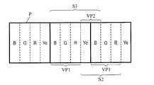
- each pixel P includes a red sub-pixel R, a green sub-pixel G, a blue sub-pixel B, and a yellow sub-pixel Ye.
- these sub-pixels are arranged in the order of a blue sub-pixel B, a green sub-pixel G, a red sub-pixel R, and a yellow sub-pixel Ye from left to right along the row direction.
- the first virtual pixel VP1 is composed of a blue subpixel B, a green subpixel G, and a red subpixel R
- the second virtual pixel VP2 is composed of a red subpixel R, a yellow subpixel Ye, and a blue subpixel B.
- the horizontal resolution is improved twice.
- the blue sub-pixel B, the green sub-pixel G, the red sub-pixel R, the yellow sub-pixel Ye, and the blue sub-pixel B are arranged in this order from the left side to the right side (that is, in order of BGRYeB).
- the first sub-pixel set S1 or the red sub-pixel R, the yellow sub-pixel Ye, the blue sub-pixel B, the green sub-pixel G, and the red sub-pixel R are arranged in this order from the left side to the right side (that is, in the order of RYeBGR). ) Displayed by the arranged second sub-pixel set S2.
- sub-pixels displaying the same primary color are located at both ends in the width direction of the two-pixel width line.
- two blue sub-pixels B are located at both ends in the width direction
- the second sub-pixel set S2 is When a two-pixel width line is displayed by using two red sub-pixels R at both ends in the width direction.
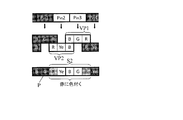
- the white pixels P in 2 and P in 3 include a second virtual pixel VP2 including a red sub-pixel R, a yellow sub-pixel Ye, and a blue sub-pixel B, and blue Rendering is performed on the first virtual pixel VP1 including the sub-pixel B, the green sub-pixel G, and the red sub-pixel R.
- the yellow sub-pixel Ye, the blue sub-pixel B, and the green sub-pixel G in the second sub-pixel set S2 displaying the white line are lit at the highest gradation.
- Two red sub-pixels R positioned at both ends so as to be sandwiched are lit with intermediate gradation.
- the blue pixel B, the green pixel G, and the yellow sub-pixel Ye located on both sides of the second sub-pixel set S2 are in a non-lighting state (that is, the lowest gradation).
- the gradation characteristic has a viewing angle dependency. That is, in the case of a liquid crystal display panel, the apparent brightness changes depending on the viewing direction, and the degree of the change varies depending on the gradation.
- the yellow sub-pixel Ye, the blue sub-pixel B, and the green sub-pixel G that are located in the center of the second sub-pixel set S2 have the highest gradation, and the second sub-pixel set S2 is sandwiched between them.
- the blue pixel B, the green pixel G, and the yellow sub-pixel Ye that are positioned have the lowest gradation.
- these boundaries that is, the two red sub-pixels R located at both ends of the second sub-pixel set S2 are intermediate gradations. For this reason, the two red sub-pixels R have different gradation characteristics from the central region of the white line and the black background region, so that the red sub-pixel R is perceived brightly depending on the viewing direction. . As a result, the white line is colored red and a false color is perceived.
- the case where the two-pixel width line is displayed using the second sub-pixel set S2 is illustrated, but the same applies to the case where the two-pixel width line is displayed using the first sub-pixel set S1.
- the white line turns blue.
- the primary color is perceived as a false color.
- the two-pixel width line is colored blue.
- the two-pixel width line is colored red.
- each pixel P is configured by a red sub-pixel R, a green sub-pixel G, a blue sub-pixel B, and a yellow sub-pixel Ye, as in the example shown in FIG.
- These sub-pixels are arranged in the order of blue sub-pixel B, green sub-pixel G, red sub-pixel R, and yellow sub-pixel Ye from left to right along the row direction.
- the first virtual pixel VP1 includes a blue subpixel B, a green subpixel G, and a red subpixel R
- the second virtual pixel VP2 includes a yellow subpixel Ye and a blue subpixel B.
- the blue sub-pixel B, the green sub-pixel G, the red sub-pixel R, the yellow sub-pixel Ye, and the blue sub-pixel B are arranged in this order from the left side to the right side (that is, in order of BGRYeB).
- the first sub-pixel set S1 or the yellow sub-pixel Ye, the blue sub-pixel B, the green sub-pixel G, and the red sub-pixel R are arranged in this order from the left side to the right side (that is, in order of YeBGR). Displayed by two sub-pixel sets S2.
- each pixel P includes a red sub-pixel R, a green sub-pixel G, a blue sub-pixel B, a cyan sub-pixel C, a magenta sub-pixel M, and a yellow sub-pixel Ye.
- these sub-pixels are cyan sub-pixel C, green sub-pixel G, magenta sub-pixel M, blue sub-pixel B, yellow sub-pixel Ye, red sub-pixel R from left to right along the row direction. Are arranged in the order.
- the first virtual pixel VP1 includes a cyan subpixel C, a green subpixel G, a magenta subpixel M, and a blue subpixel B
- the second virtual pixel VP2 includes a blue subpixel B, a yellow subpixel Ye, and a red subpixel. It is assumed that the pixel R and the cyan sub-pixel C are included. In this case, the horizontal resolution is improved twice.
- the two-pixel width line indicates that the cyan sub pixel C, the green sub pixel G, the magenta sub pixel M, the blue sub pixel B, the yellow sub pixel Ye, the red sub pixel R, and the cyan sub pixel C are arranged in this order from the left side to the right side.
- the sub-pixels B are displayed by the second sub-pixel set S2 arranged in this order from the left side to the right side (that is, in the order of BYeRCGMB).
- sub-pixels displaying the same primary color are located at both ends in the width direction of the two-pixel width line.
- two cyan sub-pixels C are located at both ends in the width direction, and the second sub-pixel set S2 is used.
- two blue sub-pixels B are located at both ends in the width direction.
- the primary color is perceived as a false color.
- the two-pixel width line is displayed using the first sub-pixel set S1
- the two-pixel width line is colored cyan.
- the two-pixel width line is colored blue.
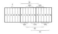
- each pixel P is configured by a red sub-pixel R, a green sub-pixel G, a blue sub-pixel B, a cyan sub-pixel C, a magenta sub-pixel M, and a yellow sub-pixel Ye.
- these sub-pixels are red sub-pixel R, cyan sub-pixel C, green sub-pixel G, magenta sub-pixel M, blue sub-pixel B, yellow sub-pixel Ye from left to right along the row direction. Are arranged in the order.
- the first virtual pixel VP1 is composed of a red subpixel R, a cyan subpixel C, and a green subpixel G
- the second virtual pixel VP2 is composed of a green subpixel G, a magenta subpixel M, and a blue subpixel B
- the third virtual pixel VP3 is composed of a blue sub-pixel B, a yellow sub-pixel Ye, and a red sub-pixel R. In this case, the horizontal resolution is improved three times.
- the three-pixel width line includes a red sub-pixel R, a cyan sub-pixel C, a green sub-pixel G, a magenta sub-pixel M, a blue sub-pixel B, a yellow sub-pixel Ye, and a red sub-pixel R from the left to the right.
- the first sub-pixel set S1 arranged in order (that is, RCGMBYeR), the green sub-pixel G, the magenta sub-pixel M, the blue sub-pixel B, the yellow sub-pixel Ye, the red sub-pixel R, the cyan sub-pixel C, and the green sub-pixel
- the second subpixel set S2 in which the pixels G are arranged in this order from the left side to the right side (that is, in the order of GMBYeRCG), or the blue subpixel B, the yellow subpixel Ye, the red subpixel R, the cyan subpixel C,
- sub-pixels displaying the same primary color are located at both ends in the width direction of the three-pixel width line.
- two red sub-pixels R are located at both ends in the width direction.
- two green sub-pixels G are located at both ends in the width direction, and the third sub-pixel set S3 is used for 3
- the pixel width line is displayed, two blue sub-pixels B are located at both ends in the width direction.
- the three-pixel width line is colored red.
- the three-pixel width line is displayed using the second sub-pixel set S2
- the three-pixel width line is colored green
- the three-pixel width line is displayed using the third sub-pixel set S3. Is displayed, the three-pixel width line is colored blue.
- liquid crystal display device 100 when an n-pixel width line is displayed, two sub-pixels (first sub-pixels) positioned at both ends in the width direction of the n-pixel width line and displaying the same primary color. And the second subpixel) are displayed such that the luminance of one (first subpixel) is lower than the original luminance and the luminance of the other (second subpixel) is higher than the original luminance. Done.
- the rendering processing unit 24 sets the pixel value to be rendered by the first subpixel to the second value. Move to sub-pixel. Therefore, the first and second sub-pixels are lit at intermediate gray levels (a gray level intermediate between the gray levels of the other sub-pixels displaying the n-pixel width line and the sub-pixels displaying the background). Is prevented. As a result, the coloration (generation of false color) of the n-pixel width line as described above is suppressed.
- FIG. 27 shows a pixel structure in the first embodiment.
- each pixel P includes four subpixels, specifically, a red subpixel R, a green subpixel G, a blue subpixel B, and a yellow subpixel Ye.
- these sub-pixels are arranged in the order of a blue sub-pixel B, a green sub-pixel G, a red sub-pixel R, and a yellow sub-pixel Ye from left to right along the row direction.
- the first virtual pixel VP1 includes a blue subpixel B, a green subpixel G, and a red subpixel R
- the second virtual pixel VP2 includes a red subpixel R, a yellow subpixel Ye, and a blue subpixel B.
- the sub-pixel shared by the first virtual pixel VP1 and the second virtual pixel VP2 is the red sub-pixel R or the blue sub-pixel B, a false color of red or blue can be generated.
- the detection of the n-pixel width line is performed by convolution (convolution operation) on the luminance component I (n) (the luminance signal generated by the luminance conversion unit 22a) using a predetermined filter. ) And see the response.
- FIG. 28 shows a filter response r when a filter of [ ⁇ 1 1 1 -1] is used as a filter for detecting (extracting) a two-pixel width line. If the absolute value of the filter response r exceeds a predetermined threshold th (that is,
- the threshold th is set to 1.75.
- processing false color suppression processing
- the rendering result is changed according to the detection result.
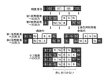
- FIGS. 29A and 29B show the relationship between the luminance signal, the output to the first virtual pixel VP1 and the second virtual pixel VP2, and the final output to each sub-pixel.
- FIG. 29A shows a case where the process for suppressing false colors is not performed
- FIG. 29B shows a case where the process for suppressing false colors is performed.
- the luminance of the right red sub-pixel R is lower than the original luminance and corresponds to the lowest gradation, and the luminance of the left red sub-pixel R is higher than the original luminance. And is equal to the sum of the original luminances of the two red sub-pixels R.
- the white line with a width of 2 pixels is rendered by the red sub-pixel R, the yellow sub-pixel Ye, the blue sub-pixel B, and the green sub-pixel G that are fully lit. The false color due to the viewing angle dependence of the gradation characteristics is not perceived.
- FIG. 30 shows a pixel structure in the second embodiment.
- each pixel P has six sub-pixels, specifically, a red sub-pixel R, a green sub-pixel G, a blue sub-pixel B, a cyan sub-pixel C, a magenta sub-pixel M, and a yellow sub-pixel Ye. Consists of. Within the pixel P, these sub-pixels are cyan sub-pixel C, green sub-pixel G, magenta sub-pixel M, blue sub-pixel B, yellow sub-pixel Ye, red sub-pixel R from left to right along the row direction. Are arranged in the order.
- the first virtual pixel VP1 includes a cyan sub pixel C, a green sub pixel G, a magenta sub pixel M, and a blue sub pixel B
- the second virtual pixel VP2 includes a blue sub pixel B, a yellow sub pixel Ye, and a red sub pixel R.
- a cyan sub-pixel C since the sub-pixel shared by the first virtual pixel VP1 and the second virtual pixel VP2 is the cyan sub-pixel C or the blue sub-pixel B, a false color of cyan or blue can occur.
- FIG. 31 shows a filter response r when a filter of [ ⁇ 1 1 1 -1] is used as a filter for detecting a two-pixel width line.
- the threshold th is set to 1.75.
- processing false color suppression processing
- the rendering result is changed according to the detection result.
- FIG. 32A and 32B show the relationship between the luminance signal, the output to the first virtual pixel VP1 and the second virtual pixel VP2, and the final output to each sub-pixel.
- FIG. 32A shows a case where the process for suppressing false color is not performed
- FIG. 32B shows a case where the process for suppressing false color is performed.
- the luminance of the blue sub-pixel B on the right side is lower than the original luminance and corresponds to the lowest gradation, and the luminance of the blue sub-pixel B on the left side is higher than the original luminance. Higher and equal to the original luminance sum of the two blue sub-pixels B.
- the white line having a width of 2 pixels is rendered by the blue subpixel B, the yellow subpixel Ye, the red subpixel R, the cyan subpixel C, the green subpixel G, and the magenta subpixel M that are fully lit.
- the blue coloring of the two-pixel width line disappears, and the false color due to the viewing angle dependence of the gradation characteristics is not perceived.
- FIG. 33 shows a pixel structure in the third embodiment.
- each pixel P has six sub-pixels, specifically, a red sub-pixel R, a green sub-pixel G, a blue sub-pixel B, a cyan sub-pixel C, a magenta sub-pixel M, and a yellow sub-pixel Ye. Consists of. Within the pixel P, these sub-pixels are red sub-pixel R, cyan sub-pixel C, green sub-pixel G, magenta sub-pixel M, blue sub-pixel B, yellow sub-pixel Ye from left to right along the row direction. Are arranged in the order.
- the first virtual pixel VP1 includes a red subpixel R, a cyan subpixel C, and a green subpixel G
- the second virtual pixel VP2 includes a green subpixel G, a magenta subpixel M, and a blue subpixel B
- the third virtual pixel VP3 includes a blue subpixel B, a yellow subpixel Ye, and a red subpixel R.
- the sub pixel shared by the first virtual pixel VP1 and the second virtual pixel VP2 is the green sub pixel G
- the sub pixel shared by the second virtual pixel VP2 and the third virtual pixel VP3 is the blue sub pixel B.
- the sub pixel shared by the third virtual pixel VP3 and the first virtual pixel VP1 is the red sub pixel R. Therefore, green, blue or red false colors can occur.
- Fig. 34 shows a filter response r when a filter of [-1.5 1 1 1-1.5] is used as a filter for detecting a three-pixel width line.
- the threshold th is set to 2.5.
- processing false color suppression processing
- the rendering result is changed according to the detection result.
- FIGS. 35A and 35B show the relationship between the luminance signal, the output to the first virtual pixel VP1, the second virtual pixel VP2, and the third virtual pixel VP3, and the final output to each sub-pixel. Show.
- FIG. 35A shows a case where the process for suppressing the false color is not performed
- FIG. 35B shows a case where the process for suppressing the false color is performed.
- the luminance of the green sub-pixel G on the right side is lower than the original luminance and corresponds to the lowest gradation, and the luminance of the green sub-pixel G on the left side is higher than the original luminance. And is equal to the original luminance sum of the two green sub-pixels G.
- a white line having a width of three pixels is rendered by the green subpixel G, the magenta subpixel M, the blue subpixel B, the yellow subpixel Ye, the red subpixel R, and the cyan subpixel C that are all lit.
- the green color of the three-pixel width line disappears, and the false color due to the viewing angle dependency of the gradation characteristics is not perceived.
- Example 4 The pixel structure in the fourth embodiment is the same as that in the first embodiment. Further, the detection of the n-pixel width line (that is, the detection of the area where the false color is generated) is performed in the same manner as in the first embodiment. However, the fourth embodiment differs from the first embodiment in the manner in which the rendering result changes when the occurrence of a false color is detected.
- FIG. 36 shows the relationship among the luminance signal, the output to the first virtual pixel VP1 and the second virtual pixel VP2, and the final output to each sub-pixel.
- the pixel value to be rendered by the right red sub-pixel Rs is moved to the left red sub-pixel Rd in the even-numbered rows of the plurality of pixel rows.
- the pixel value to be rendered by the left red sub-pixel Rd is moved to the right red sub-pixel Rs.
- the white line with a width of 2 pixels is the RYeBG (red sub-pixel R, yellow sub-pixel Ye, blue sub-pixel B and green sub-pixel G) in the fully lit state, or YeBGR (yellow sub-pixel Ye, in the fully lit state).
- the red color of the two-pixel width line disappears, and a false color due to the viewing angle dependency of the gradation characteristics is perceived. It will not be done.
- the red sub-pixel R (second sub-pixel) having lower luminance than the original has one end and the other end in the width direction of the two-pixel width line along the direction in which the two-pixel width line extends. Will be located alternately. In other words, the lighting position of the red sub-pixel R is switched for each row. For this reason, in this embodiment, the position of the average white line (broken line in FIG. 36) does not shift compared to before performing the false color suppression process.
- the direction in which the pixel value of the red sub-pixel R is shifted is changed for each row (even-numbered rows are from right to left, and odd-numbered rows are from left to right). For this reason, color deviation does not occur. Since the color deviation often causes another false color generation, it can be said that the generation of the false color can be further suppressed in this embodiment as compared with the first embodiment.
- the embodiment of the present invention it is possible to provide a multi-primary color display device capable of displaying an image having the same or higher resolution without reducing the sub-pixel size as compared with the three primary color display device.
- multi-primary color display panel 20 signal conversion circuit 21 low-frequency multi-primary color signal generation unit 21a low-pass filter (low-frequency component extraction unit) 21b Multi-primary color conversion unit 22 High frequency luminance signal generation unit 22a Luminance conversion unit 22b High pass filter (high frequency component extraction unit) 23 Detection unit (false color generation detection unit) 24 Rendering processing unit 25 ⁇ correction unit 26 Reverse ⁇ correction unit 100 Liquid crystal display device (multi-primary color display device) P pixel SP1 to SP6 sub pixel R red sub pixel G green sub pixel B blue sub pixel C cyan sub pixel M magenta sub pixel Ye yellow sub pixel VP1 first virtual pixel VP2 second virtual pixel VP3 third virtual pixel
Landscapes
- Engineering & Computer Science (AREA)
- Physics & Mathematics (AREA)
- Computer Hardware Design (AREA)
- General Physics & Mathematics (AREA)
- Theoretical Computer Science (AREA)
- Chemical & Material Sciences (AREA)
- Crystallography & Structural Chemistry (AREA)
- Control Of Indicators Other Than Cathode Ray Tubes (AREA)
- Liquid Crystal Display Device Control (AREA)
Abstract
多原色表示装置(100)は、各画素(P)を構成する複数のサブ画素を、それぞれが2つ以上のサブ画素から構成されるn個(nは2以上の整数)の仮想画素に振り分け、n個の仮想画素のそれぞれを最小のカラー表示単位として表示を行うことができる。各仮想画素を構成する2つ以上のサブ画素は、他の仮想画素と共通のサブ画素を含んでいる。n個の仮想画素に対応する幅を有する線が表示される際、線の幅方向における両端に位置し、互いに同じある原色を表示する第1および第2のサブ画素のうちの第1のサブ画素の輝度は、本来の輝度よりも低く、第2のサブ画素の輝度は、本来の輝度よりも高い。
Description
本発明は、表示装置に関し、特に、4つ以上の原色を用いて表示を行う多原色表示装置に関する。
一般的な表示装置では、光の三原色である赤、緑および青を表示する3つのサブ画素によって1つの画素が構成されており、そのことによってカラー表示が可能になっている。
しかしながら、従来の表示装置は、表示可能な色の範囲(「色再現範囲」と呼ばれる。)が狭いという問題を有している。色再現範囲が狭いと、物体色(自然界に存在する様々な物体の色である;非特許文献1参照)の一部を表示することができない。そこで、表示装置の色再現範囲を広くするために、表示に用いる原色の数を増やす手法が提案されている。
例えば、特許文献1には、6つの原色を用いて表示を行う表示装置が開示されている。また、特許文献1には、4つの原色を用いて表示を行う表示装置や、5つの原色を用いて表示を行う表示装置も開示されている。6つの原色を用いて表示を行う表示装置の一例を図37に示す。図37に示す表示装置800では、赤サブ画素R、緑サブ画素G、青サブ画素B、シアンサブ画素C、マゼンタサブ画素Mおよび黄サブ画素Yeによって1つの画素Pが構成される。この表示装置800では、6つのサブ画素によって表示される赤、緑、青、シアン、マゼンタおよび黄の6つの原色を混色することにより、カラー表示が行われる。
表示に用いる原色の数を増やす、つまり、4つ以上の原色を用いて表示を行うことにより、三原色を用いて表示を行う従来の表示装置よりも色再現範囲を広くすることができる。本願明細書では、4つ以上の原色を用いて表示を行う表示装置を「多原色表示装置」と称し、3つの原色を用いて表示を行う(つまり従来の一般的な)表示装置を「三原色表示装置」と称する。
M. R. Pointer, "The gamut of real surface colors", Color Research and Application, Vol.5, No.3, pp.145-155 (1980)
しかしながら、多原色表示装置で、三原色表示装置と同等の解像度を有する画像を表示するためには、画面サイズが同一の場合、デバイス構造の細密化が必要となり、生産コストが増大してしまう。これは、多原色表示装置では1画素あたりのサブ画素の数が3から4以上に増加するので、同一画面サイズで同一画素数を実現するためには、三原色表示装置と比べてサブ画素のサイズを小さくしなくてはならないからである。具体的には、表示に用いる原色の数をm(m≧4)とすると、サブ画素のサイズを3/mにしなくてはならない。例えば、6つの原色を用いて表示を行う多原色表示装置では、サブ画素のサイズを1/2(=3/6)にする必要がある。
本発明は、上記問題に鑑みてなされたものであり、その目的は、三原色表示装置と比べてサブ画素サイズを小さくすることなく、同等またはより高い解像度の画像を表示することができる多原色表示装置を提供することにある。
本発明の実施形態における多原色表示装置は、複数の行および複数の列を含むマトリクス状に配置された複数の画素を有し、前記複数の画素のそれぞれは、互いに異なる原色を表示する少なくとも4つのサブ画素を含む複数のサブ画素によって構成される多原色表示装置であって、各画素を構成する前記複数のサブ画素を、それぞれが2つ以上のサブ画素から構成されるn個(nは2以上の整数)の仮想画素に振り分け、前記n個の仮想画素のそれぞれを最小のカラー表示単位として表示を行うことができ、前記n個の仮想画素のそれぞれを構成する前記2つ以上のサブ画素は、他の仮想画素と共通のサブ画素を含んでおり、前記n個の仮想画素に対応する幅を有する線が表示される際、前記線の幅方向における両端に位置し、互いに同じある原色を表示する第1および第2のサブ画素のうちの第1のサブ画素の輝度は、本来の輝度よりも低く、第2のサブ画素の輝度は、本来の輝度よりも高い。
ある実施形態において、前記n個の仮想画素に対応する幅を有する前記線は白線であり、黒い背景中に前記白線が表示される際、前記第1のサブ画素の輝度は、最低階調に対応する輝度であり、前記第2のサブ画素の輝度は、前記第1のサブ画素の本来の輝度と前記第2のサブ画素の本来の輝度との和に等しい。
ある実施形態において、前記第2のサブ画素は、前記線が延びる方向に沿って、前記線の幅方向における一端および他端に交互に位置する。
ある実施形態において、上述した構成を有する多原色表示装置は、3原色に対応した入力画像信号を、4つ以上の原色に対応した多原色画像信号に変換する信号変換回路を備える。
ある実施形態において、前記信号変換回路は、前記n個の仮想画素に対応する幅を有する前記線が表示されることを検出する検出部を有する。
ある実施形態において、前記信号変換回路は、入力画像信号に基づいて、入力画像信号の低域成分が多原色化された信号である低域多原色信号を生成する低域多原色信号生成部と、入力画像信号に基づいて、入力画像信号の高域成分が輝度変換された信号である高域輝度信号を生成する高域輝度信号生成部と、前記低域多原色信号生成部によって生成された低域多原色信号および前記高域輝度信号生成部によって生成された高域輝度信号に基づいて、前記n個の仮想画素へのレンダリング処理を行うレンダリング処理部と、を有する。
ある実施形態において、前記低域多原色信号生成部は、入力画像信号から低域成分を抽出する低域成分抽出部と、前記低域成分抽出部によって抽出された入力画像信号の低域成分を多原色化する多原色変換部と、を有する。
ある実施形態において、前記高域輝度信号生成部は、入力画像信号を輝度変換して輝度信号を生成する輝度変換部と、前記輝度変換部によって生成された輝度信号の高域成分を高域輝度信号として抽出する高域成分抽出部と、を有する。
ある実施形態において、上述した構成を有する多原色表示装置は、前記複数の画素のそれぞれに前記複数のサブ画素を有する多原色表示パネルを備える。
ある実施形態において、前記複数の行は、表示面の水平方向に略平行であり、前記複数の画素のそれぞれ内で、前記複数のサブ画素は1行複数列に配列されており、前記線は、列方向に延びる。
ある実施形態において、前記複数のサブ画素は、赤を表示する赤サブ画素、緑を表示する緑サブ画素および青を表示する青サブ画素を含む。
ある実施形態において、前記複数のサブ画素は、シアンを表示するシアンサブ画素、マゼンタを表示するマゼンタサブ画素、黄を表示する黄サブ画素および白を表示する白サブ画素のうちの少なくとも1つを含む。
ある実施形態において、前記複数のサブ画素は、赤を表示するさらなる赤サブ画素を含む。
ある実施形態において、上述した構成を有する多原色表示装置は、液晶表示装置である。
本発明の実施形態によると、三原色表示装置と比べてサブ画素サイズを小さくすることなく、同等またはより高い解像度の画像を表示することができる多原色表示装置を提供することができる。また、本発明の実施形態によると、解像度向上のために複数の仮想画素を用いた表示を行う場合において、特定の表示を行うときの偽色の発生を抑制することができる。
以下、図面を参照しながら本発明の実施形態を説明する。なお、以下では液晶表示装置を例示するが、本発明は液晶表示装置に限定されるものではなく、有機EL表示装置などの他の表示装置にも好適に用いられる。
図1に、本実施形態における液晶表示装置100を示す。液晶表示装置100は、図1に示すように、多原色表示パネル10と、信号変換回路20とを備え、4つ以上の原色を用いて表示を行う多原色表示装置である。
図1には示されていないが、多原色表示パネル10は、複数の行および複数の列を含むマトリクス状に配置された複数の画素を有する。複数の画素のそれぞれは、複数のサブ画素によって構成される。各画素を構成する複数のサブ画素は、互いに異なる原色を表示する少なくとも4つのサブ画素を含む。図2に、多原色表示パネル10の具体的な画素構造(サブ画素配列)の例を示す。
図2に示す多原色表示パネル10では、マトリクス状に配置された複数の画素Pのそれぞれは、6つのサブ画素SP1~SP6によって構成される。各画素P内で、6つのサブ画素SP1~SP6は、1行6列に配列されている。6つのサブ画素SP1~SP6は、例えば、赤を表示する赤サブ画素R、緑を表示する緑サブ画素G、青を表示する青サブ画素B、シアンを表示するシアンサブ画素C、マゼンタを表示するマゼンタサブ画素Mおよび黄を表示する黄サブ画素Yeである。
なお、多原色表示パネル10の画素構造は、図2に示す例に限定されない。図3および図4に、多原色パネル10の画素構造の他の例を示す。
図3に示す多原色表示パネル10では、マトリクス状に配置された複数の画素Pのそれぞれは、5つのサブ画素SP1~SP5によって構成される。各画素P内で、5つのサブ画素SP1~SP5は、1行5列に配列されている。5つのサブ画素SP1~SP5は、例えば、赤サブ画素R、緑サブ画素Gおよび青サブ画素Bと、シアンサブ画素C、マゼンタサブ画素Mおよび黄サブ画素Yeのうちのいずれか2つとである。
図4に示す多原色表示パネル10では、マトリクス状に配置された複数の画素Pのそれぞれは、4つのサブ画素SP1~SP4によって構成される。各画素P内で、4つのサブ画素SP1~SP4は、1行4列に配列されている。4つのサブ画素SP1~SP4は、例えば、赤サブ画素R、緑サブ画素Gおよび青サブ画素Bと、シアンサブ画素C、マゼンタサブ画素Mおよび黄サブ画素Yeのうちのいずれか1つとである。
なお、各画素Pを構成する複数のサブ画素は、必ずしも互いに異なる色を表示するサブ画素だけを含んでいる必要はない。例えば、シアンサブ画素C、マゼンタサブ画素Mおよび黄サブ画素Yeのいずれかに代えて、赤を表示するさらなる赤サブ画素Rを設けてもよい。1つの画素P内に赤サブ画素Rを2つ設けると、明るい(明度の高い)赤を表示することができる。あるいは、シアンサブ画素C、マゼンタサブ画素Mおよび黄サブ画素Yeのいずれかに代えて、白を表示する白サブ画素Wを設けてもよい。白サブ画素Wを設けると、画素P全体での表示輝度を向上させることができる。
また、図2~図4には、複数のサブ画素が各画素P内で1行複数列に配列されている構成を例示したが、画素P内におけるサブ画素配列はこれに限定されず、例えば、各画素P内で複数のサブ画素が複数行1列に配列されていてもよい。ただし、ある方向について解像度の向上効果を得るためには、各画素P内でその方向に沿ってサブ画素が複数存在することが好ましい。従って、行方向について解像度の向上効果を得る観点からは、各画素P内で複数のサブ画素が2列以上に配列されていることが好ましく、列方向について解像度の向上効果を得る観点からは、各画素P内で複数のサブ画素が2行以上に配列されていることが好ましい。また、人間の目の分解能は、水平方向よりも垂直方向に対して低いので、少なくとも水平方向の解像度を向上させることが好ましく、さらに、典型的には、行方向が(つまり複数の画素Pによって構成される複数の行が)表示面の水平方向に略平行である。従って、一般的な用途では、各画素P内で複数のサブ画素が1行複数列に配列されていることが好ましいといえる。以下では、特にことわらない限り、画素行が表示面の水平方向に略平行であり、各画素P内で複数のサブ画素が1行複数列に配列されている場合を例として説明を行う。
信号変換回路20は、図1に示すように、3原色(RGB)に対応した入力画像信号(三原色画像信号)を、4つ以上の原色に対応した画像信号(「多原色画像信号」と称する。)に変換する。信号変換回路20から出力された多原色画像信号が多原色表示パネル10に入力され、4つ以上の原色を用いたカラー表示が行われる。信号変換回路20の具体的な構成については後に詳述する。
本願明細書では、多原色表示パネル10が有する複数の画素Pの総数を「パネル解像度」と称する。複数の画素Pが行方向にA個、列方向にB個配置されているときのパネル解像度は「A×B」と表記される。また、本願明細書では、入力画像の最小表示単位も便宜的に「画素」と呼び、入力画像の総画素数を「入力画像の解像度」と称する。この場合も、行方向にA個、列方向にB個の画素から構成される入力画像の解像度は「A×B」と表記される。
本実施形態における液晶表示装置100は、各画素Pを構成する複数のサブ画素を複数の仮想的な画素(以下では「仮想画素」と呼ぶ。)に振り分け、これら複数の仮想画素のそれぞれを最小のカラー表示単位として表示を行うことができる。図5、図6および図7に、複数の仮想画素への複数のサブ画素の振り分けパターンの例を示す。
図5に示す振り分けパターンでは、各画素Pを構成する6つのサブ画素SP1~SP6は、2個の仮想画素(第1および第2仮想画素)VP1およびVP2に振り分けられる。第1仮想画素VP1は、6つのサブ画素SP1~SP6のうちの4つのサブ画素SP1、SP2、SP3およびSP4によって構成される。また、第2仮想画素VP2は、3つのサブ画素SP4、SP5およびSP6によって構成される。図5に示す例では、画素P内で左側から4番目に位置するサブ画素SP4は、第1仮想画素VP1および第2仮想画素VP2の両方を構成する。つまり、第1仮想画素VP1および第2仮想画素VP2は、共通のサブ画素SP4を含んでおり、そのサブ画素SP4を共用する。
図6に示す振り分けパターンでは、各画素Pを構成する5つのサブ画素SP1~SP5は、2個の仮想画素(第1および第2仮想画素)VP1およびVP2に振り分けられる。第1仮想画素VP1は、5つのサブ画素SP1~SP5のうちの3つのサブ画素SP1、SP2およびSP3によって構成される。また、第2仮想画素VP2は、3つのサブ画素SP3、SP4およびSP5によって構成される。図6に示す例では、画素P内で中央に位置するサブ画素SP3は、第1仮想画素VP1および第2仮想画素VP2の両方を構成する。つまり、第1仮想画素VP1および第2仮想画素VP2は、共通のサブ画素SP3を含んでおり、そのサブ画素SP3を共用する。
図7に示す振り分けパターンでは、各画素Pを構成する4つのサブ画素SP1~SP4は、2個の仮想画素(第1および第2仮想画素)VP1およびVP2に振り分けられる。第1仮想画素VP1は、4つのサブ画素SP1~SP4のうちの3つのサブ画素SP1、SP2およびSP3によって構成される。また、第2仮想画素VP2は、2つのサブ画素SP3およびSP4によって構成される。図7に示す例では、画素P内で左側から3番目に位置するサブ画素SP3は、第1仮想画素VP1および第2仮想画素VP2の両方を構成する。つまり、2つの仮想画素VP1およびVP2は、共通のサブ画素SP3を含んでおり、そのサブ画素SP3を共用する。
なお、図5~図7に例示した振り分けパターンでは、仮想画素の個数は2であるが、仮想画素の個数は2に限定されるものではなく、3以上であってもよい。画素Pを構成する複数のサブ画素は、n個(nは2以上の整数)の仮想画素に振り分けられる。図8に、振り分けパターンの他の例を示す。
図8に示す振り分けパターンでは、各画素Pを構成する6つのサブ画素SP1~SP6は、3個の仮想画素(第1、第2および第3仮想画素)VP1、VP2およびVP3に振り分けられる。第1仮想画素VP1は、6つのサブ画素SP1~SP6のうちの3つのサブ画素SP1、SP2およびSP3によって構成される。また、第2仮想画素VP2は、3つのサブ画素SP3、SP4およびSP5によって構成される。さらに、第3仮想画素VP3は、2つのサブ画素SP5およびSP6によって構成される。図8に示す例では、画素P内で左側から3番目に位置するサブ画素SP3は、第1仮想画素VP1および第2仮想画素VP2の両方を構成する。つまり、第1仮想画素VP1および第2仮想画素VP2は、共通のサブ画素SP3を含んでおり、そのサブ画素SP3を共用する。また、画素P内で左側から5番目に位置するサブ画素SP5は、第2仮想画素VP2および第3仮想画素VP3の両方を構成する。つまり、第2仮想画素VP2および第3仮想画素VP3は、共通のサブ画素SP5を含んでおり、そのサブ画素SP5を共用する。
また、図5~図8に例示した振り分けパターンでは、複数の仮想画素のそれぞれが、1つの画素P内で連続する2つ以上のサブ画素によって構成されているが、本発明はこのような振り分けパターンに限定されるものではない。図9~図12に、振り分けパターンの他の例を示す。
図9に示す振り分けパターンでは、複数のサブ画素SP1~SP4は、2個の仮想画素VP1およびVP2に振り分けられ、図10に示す振り分けパターンでは、複数のサブ画素SP1~SP5は、2個の仮想画素VP1およびVP2に振り分けられる。また、図11に示す振り分けパターンでは、複数のサブ画素SP1~SP6は、2個の仮想画素VP1およびVP2に振り分けられ、図12に示す振り分けパターンでは、複数のサブ画素SP1~SP6は、3個の仮想画素VP1、VP2およびVP3に振り分けられる。
図9の中央付近に示している2個の仮想画素VP1およびVP2のうちの第1仮想画素VP1は、中央の画素Pの3つのサブ画素SP1、SP2およびSP3によって構成される。また、第2仮想画素VP2は、中央の画素Pの2つのサブ画素SP3およびSP4と、右側の画素Pの1つのサブ画素SP1とによって構成される。この例では、第1仮想画素VP1は、画素P内で左側から3番目に位置するサブ画素SP3を第2仮想画素VP2と共有する。また、第2仮想画素VP2は、画素P内でもっとも左側に位置するサブ画素SP1を別の第1仮想画素(右側の画素Pの3つのサブ画素SP1、SP2およびSP3によって構成される仮想画素)VP1と共有する。
図10の中央付近に示している2個の仮想画素VP1およびVP2のうちの第1仮想画素VP1は、中央の画素Pの3つのサブ画素SP1、SP2およびSP3によって構成される。また、第2仮想画素VP2は、中央の画素Pの3つのサブ画素SP3、SP4およびSP5と、右側の画素Pの1つのサブ画素SP1とによって構成される。この例では、第1仮想画素VP1は、画素P内で左側から3番目に位置するサブ画素SP3を第2仮想画素VP2と共有する。また、第2仮想画素VP2は、画素P内でもっとも左側に位置するサブ画素SP1を別の第1仮想画素(右側の画素Pの3つのサブ画素SP1、SP2およびSP3によって構成される仮想画素)VP1と共有する。
図11の中央付近に示している2個の仮想画素VP1およびVP2のうちの第1仮想画素VP1は、中央の画素Pの4つのサブ画素SP1、SP2、SP3およびSP4によって構成される。また、第2仮想画素VP2は、中央の画素Pの3つのサブ画素SP4、SP5およびSP6と、右側の画素Pの1つのサブ画素SP1とによって構成される。この例では、第1仮想画素VP1は、画素P内で左側から4番目に位置するサブ画素SP4を第2仮想画素VP2と共有する。また、第2仮想画素VP2は、画素P内でもっとも左側に位置するサブ画素SP1を別の第1仮想画素(右側の画素Pの4つのサブ画素SP1、SP2、SP3およびSP4によって構成される仮想画素)VP1と共有する。
図12の中央付近に示している3個の仮想画素VP1、VP2およびVP3のうちの第1仮想画素VP1は、中央の画素Pの3つのサブ画素SP1、SP2およびSP3によって構成される。また、第2仮想画素VP2は、中央の画素Pの3つのサブ画素SP3、SP4およびSP5によって構成されており、第3仮想画素VP3は、中央の画素Pの2つのサブ画素SP5およびSP6と、右側の画素Pの1つのサブ画素SP1とによって構成される。この例では、第1仮想画素VP1は、画素P内で左側から3番目に位置するサブ画素SP3を第2仮想画素VP2と共有する。また、第2仮想画素VP2は、画素P内で左側から5番目に位置するサブ画素SP5を第3仮想画素VP3と共有する。第3仮想画素VP3は、画素P内でもっとも左側に位置するサブ画素SP1を別の第1仮想画素(右側の画素Pの3つのサブ画素SP1、SP2およびSP3によって構成される仮想画素)VP1と共有する。
図9~図12に示した例では、第2仮想画素VP2または第3仮想画素VP3は、2つの画素Pにまたがって連続する複数のサブ画素によって構成される。このように、一部の仮想画素が2つの画素Pにまたがっていてもよい。
上述したように、本実施形態における液晶表示装置100では、各画素Pを構成する複数のサブ画素をn個の(複数の)仮想画素に振り分け、各仮想画素を最小のカラー表示単位として表示を行うことができる。そのため、表示解像度(表示面に表示される画像の解像度)をパネル解像度(画素Pの総数によって規定されるパネル固有の物理的な解像度)よりも高くすることができる。
例えば、図5~図7および図9~図11に示した振り分けパターンによれば、各画素Pについて行方向(水平方向)に隣接した2個の仮想画素VP1およびVP2が構成されるので、表示解像度を水平方向について2倍にすることができる。そのため、解像度が「2A×B」の入力画像を、パネル解像度が「A×B」の多原色表示パネル10で表示することができる。また、図8および図12に示した振り分けパターンによれば、各画素Pについて行方向(水平方向)に隣接した3個の仮想画素VP1、VP2およびVP3が構成されるので、表示解像度を水平方向について3倍にすることができる。そのため、解像度が「3A×B」の入力画像を、パネル解像度が「A×B」の多原色表示パネル10で表示することができる。
従って、本実施形態における液晶表示装置100では、入力画像の解像度がパネル解像度よりも高い場合であっても好適に表示を行うことができる。あるいは、表示面の一部に入力画像を縮小して表示することもできる。
このように、本実施形態における液晶表示装置(多原色表示装置)100は、表示解像度をパネル解像度よりも高くすることができるので、三原色表示装置と同一のサブ画素サイズおよび画面サイズで、同等またはより高い解像度の画像を表示することができ、また、三原色表示装置と同等のコストで生産することができる。
また、本実施形態における液晶表示装置100では、各仮想画素を構成する複数のサブ画素が、他の仮想画素と共通のサブ画素を含んでいる(つまり同じ原色を表示するサブ画素を他の仮想画素と共通に割り当てられている)。このように複数の仮想画素でサブ画素を共用することにより、各仮想画素を構成するサブ画素の個数・種類が増えるので、各仮想画素で十分な輝度を確保しやすく、また、所望の色(例えば白)の再現が容易となる。
ただし、本願発明者の検討によれば、各仮想画素を構成するサブ画素が、他の仮想画素と共通のサブ画素を含んでいる場合、特定の表示を行うときに偽色が発生し得ることがわかった。具体的には、n個の仮想画素に対応する幅を有する線が表示される際(つまり入力画像信号におけるn画素幅の線が、解像度をn倍向上させる態様で表示される際)に、その線が特定の原色に色付いてしまうことがわかった。以下の説明では、上述した線を「n画素幅線」と呼ぶこともある。図5~図12に例示したように各画素Pについてn個の仮想画素が行方向(水平方向)に隣接するように構成される場合、n画素幅線は、列方向(垂直方向)に延びる線である。
本実施形態における液晶表示装置100は、n画素幅線が表示される際、n画素幅線の幅方向における両端に位置し、互いに同じある原色を表示する2つのサブ画素(第1のサブ画素および第2サブ画素)のうちの一方(第1のサブ画素)の輝度が本来の輝度よりも低くなり、他方(第2のサブ画素)の輝度が本来の輝度よりも高くなるように表示を行う。これにより、n画素幅線の色付き(偽色の発生)が抑制される。このような効果が得られる理由や偽色が発生する原因等については、後に詳述する。
次に、信号変換回路20の具体的な構成を説明する。図13に、信号変換回路20の具体的な構成の例を示す。
信号変換回路20は、図13に示すように、低域多原色信号生成部21と、高域輝度信号生成部22と、検出部(偽色発生検出部)23と、レンダリング処理部24とを有する。信号変換回路20は、さらに、γ補正部25と、逆γ補正部26とを有する。
信号変換回路20への入力画像信号は、まず、γ補正部25によってγ補正処理を施される。γ補正処理を施された画像信号は、次に、低域多原色信号生成部21と、高域輝度信号生成部22とにそれぞれ入力される。
低域多原色信号生成部21は、入力画像信号に基づいて、低域多原色信号を生成する。低域多原色信号は、入力画像信号の低域成分(相対的に空間周波数が低い成分)が多原色化された(つまり4つ以上の原色に対応するように変換がなされた)信号である。
低域多原色信号生成部21は、具体的には、低域成分抽出部(ここではローパスフィルタ:LPF)21aと、多原色変換部21bとを有する。ローパスフィルタ21aは、入力画像信号から低域成分を抽出する。ローパスフィルタ21aによって抽出された入力画像信号の低域成分は、多原色変換部21bによって多原色化される。多原色化された低域成分は、低域多原色信号として出力される。なお、多原色変換部21bにおける多原色化の手法としては、公知の種々の手法を用いることができる。例えば、国際公開第2008/065935号や国際公開第2007/097080号に開示されている手法を用いることができる。
高域輝度信号生成部22は、入力画像信号に基づいて、高域輝度信号を生成する。高域輝度信号は、入力画像信号の高域成分(相対的に空間周波数が高い成分)が輝度変換された信号である。
高域輝度信号生成部22は、具体的には、輝度変換部22aと、高域成分抽出部(ここではハイパスフィルタ:HPF)22bとを有する。輝度変換部22aは、入力画像信号を輝度変換して輝度信号(以下では「輝度成分」と呼ぶこともある)を生成する。ハイパスフィルタ22bは、輝度変換部22aによって生成された輝度信号の高域成分を、高域輝度信号として抽出する。
偽色発生検出部23は、n画素幅線が表示されることを検出する。つまり、偽色発生検出部23は、n画素幅線が表示されるか否かの判定を行う。ここでは、偽色発生検出部23は、輝度変換部22aによって生成された輝度信号(輝度成分)に基づいて判定(検出)を行う。
レンダリング処理部24は、低域多原色信号生成部21によって生成された低域多原色信号と、高域輝度信号生成部22によって生成された高域輝度信号とに基づいて、複数の仮想画素へのレンダリング処理を行う。また、レンダリング処理部24は、偽色発生検出部23によってn画素線幅が表示されることが検出された場合には、上述した第1のサブ画素の輝度が本来の輝度よりも低くなり、第2のサブ画素の輝度が本来の輝度よりも高くなるよう、レンダリング処理を行う。レンダリング処理によって生成された画像信号は、逆γ補正部26によって逆γ補正を施され、多原色画像信号として出力される。
このように、信号変換回路20では、色信号に対してよりも輝度信号に対して感度が優れる(つまり輝度の視感度に比べて色差の視感度は低い)という人間の視覚特性を考慮し、入力画像信号の低域成分に対しては多原色化処理を行い、高域成分に対しては輝度変換処理を行う。これらの処理によって得られた低域多原色信号と高域輝度信号とを組み合わせ、仮想画素へレンダリングすることにより、4つ以上の原色に対応した画像信号(多原色画像信号)を出力することができる。
続いて、仮想画素へのレンダリングを具体的に説明する。
まず、各画素Pについて2個の仮想画素(第1仮想画素および第2仮想画素)を構成する場合について説明を行う。各画素Pについて2個の仮想画素を構成する場合(つまり複数のサブ画素を2個の仮想画素に振り分ける場合)、仮想画素を考慮したレンダリング結果V(n,m)は、下記式から算出される。

ここで、nは行方向における画素位置、mは画素内におけるサブ画素位置、L(n,m)は画素位置nにおける第m原色の低域成分、H(n)は画素位置nにおける輝度の高域成分である。また、P(n,m)はL(n,m)およびH(n)から算出される画素値、αは高域成分の強調係数(通常はα=1)、W(g,m)は第g仮想画素における第m原色の重み(重み係数とも呼ぶ)である。また、図14に、ある画素行の一部について、低域成分、高域成分、画素値、第1仮想画素における各原色の重み、第2仮想画素における各原色の重みおよび仮想画素を考慮したレンダリング結果を示す。
上記式および図14から、2個の仮想画素によって、出力側における1個の画素(レンダリング結果V(n,m)で表される)に対し、入力側における2個の画素の画素値P(2n-1,m)とP(2n,m)、あるいはP(2n,m)とP(2n+1,m)がレンダリングされていることが分かる。つまり、入力側における2個の画素分の情報を、出力側における1個の画素で表示し得ることがわかる。
図15に、第1仮想画素における第m原色の重みW(1,m)および第2仮想画素における第m原色の重みW(2,m)を下記表1に示すように設定したときの画素値およびレンダリング結果を示す。また、図16(a)、(b)および(c)に、図15に示すレンダリング結果で表されるある画素行の一部を、入力側、入力側(ただし多原色変換後)および出力側について模式的に示す。
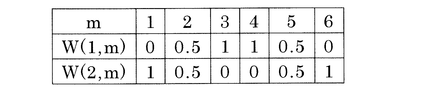
表1に示す重み(重み係数)は、いずれも「0」、「1」または「0.5」に設定されている。ある仮想画素について、重みが1に設定されている原色を表示するサブ画素は、出力し得る輝度のすべてをその仮想画素の表示に寄与させることができる。また、重みが0に設定されている原色を表示するサブ画素は、その仮想画素の表示に全く寄与しない。つまり、重みが0に設定されている原色を表示するサブ画素は、その仮想画素を構成しないといえる。また、重みが0.5に設定されている原色を表示するサブ画素は、出力し得る輝度の半分をその仮想画素の表示に寄与させることができる。このように、複数の画素について重みが0を超える(ただし1未満)ように設定されている原色を表示するサブ画素は、複数の仮想画素の表示に寄与するので、複数の仮想画素に共通に含まれる(複数の仮想画素に共用される)。表1に示すように重みを設定した場合、第1仮想画素は、第2、第3、第4および第5原色を表示する4つのサブ画素によって構成され、第2仮想画素は、第1、第2、第5および第6原色を表示する4つのサブ画素によって構成されることになる。
図16(a)および(c)に示している例においては、出力側におけるサブ画素のサイズは、入力側におけるサブ画素のサイズと同じである。従って、出力側における画素数は、入力側における画素数の1/2である。本来であれば、入力側と同等の解像度の画像を表示するためには、出力側におけるサブ画素のサイズは、図16(b)に示すような多原色変換後の入力側のサブ画素のサイズと同じである必要がある。しかしながら、2つの仮想画素を用いたレンダリングにより、図16(c)に示しているように、入力側と比較してサブ画素サイズが同じで画素数が1/2である出力側において、入力側と同等の解像度で画像を表示することが可能となる。
次に、各画素Pについて3個の仮想画素(第1仮想画素、第2仮想画素および第3仮想画素)を構成する場合について説明を行う。各画素Pについて3個の仮想画素を構成する場合(つまり複数のサブ画素を3個の仮想画素に振り分ける場合)、仮想画素を考慮したレンダリング結果V(n,m)は、下記式から算出される。

仮想画素が2個の場合の式について説明したのと同様、nは行方向における画素位置、mは画素内におけるサブ画素位置、L(n,m)は画素位置nにおける第m原色の低域成分、H(n)は画素位置nにおける輝度の高域成分である。また、P(n,m)はL(n,m)およびH(n)から算出される画素値、αは高域成分の強調係数(通常はα=1)、W(g,m)は第g仮想画素における第m原色の重み(重み係数)である。また、図17に、ある画素行の一部について、低域成分、高域成分、画素値、第1仮想画素における各原色の重み、第2仮想画素における各原色の重み、第3仮想画素における各原色の重みおよび仮想画素を考慮したレンダリング結果を示す。
上記式および図17から、3個の仮想画素によって、出力側における1個の画素(レンダリング結果V(n,m)で表される)に対し、入力側における3個の画素の画素値P(3n-2,m)とP(3n-1,m)とP(3n,m)、あるいはP(3n-1,m)とP(3n,m)とP(3n+1,m)、あるいはP(3n,m)とP(3n+1,m)とP(3n+2,m)がレンダリングされていることが分かる。つまり、入力側における3個の画素分の情報を、出力側における1個の画素で表示し得ることがわかる。
図18に、第1仮想画素における第m原色の重みW(1,m)、第2仮想画素における第m原色の重みW(2,m)および第3仮想画素における第m原色の重みW(3,m)を下記表2に示すように設定したときの画素値およびレンダリング結果を示す。また、図19(a)、(b)および(c)に、図18に示すレンダリング結果で表されるある画素行の一部を、入力側、入力側(ただし多原色変換後)および出力側について模式的に示す。
表2に示すように重みを設定した場合、第1仮想画素は、第1、第2および第6原色を表示する3つのサブ画素によって構成されることになる。また、第2仮想画素は、第2、第3および第4原色を表示する3つのサブ画素によって構成され、第3仮想画素は、第4、第5および第6原色を表示する3つのサブ画素によって構成されることになる。
図19(a)および(c)に示している例では、出力側におけるサブ画素のサイズは、入力側におけるサブ画素のサイズと同じである。従って、出力側における画素数は、入力側における画素数の1/2である。本来であれば、入力側よりも高い解像度の画像を表示するためには、出力側におけるサブ画素のサイズは、図19(b)に示すような多原色変換後の入力側のサブ画素のサイズよりも小さい必要がある。しかしながら、3つの仮想画素を用いたレンダリングにより、図19(c)に示しているように、入力側と比較してサブ画素サイズが同じで画素数が1/2である出力側において、入力側よりも高い解像度で画像を表示することが可能となる。
上述したように、1つの画素Pにつき複数の仮想画素を考慮したレンダリング処理により、表示解像度を向上させることができる。また、図16に示した例と、図19に示した例との比較からわかるように、同じ多原色表示パネル10を用いた場合でも、仮想画素の振り分けパターンによって表示可能な解像度を変えることができる。そのため、入力する画像の種類(コンテンツ)やその表示方法(全体表示、縮小表示など)によって、適切な解像度を選択することが可能になる。
図20および図21に、縮小表示の具体例を示す。図20に示す例では、表示面を2行2列の4つの領域に分割し、それぞれ1/2に縮小された4つの画像IG1~IG4を同時に表示している。この例では、4画面の同時視聴が可能になる。また、図21に示す例では、表示面全体に表示された画像IG1の一部に重なるように、1/3に縮小された画像IG2が表示されている。この例では、主画面を視聴しながら、副画面で副次的な情報(例えば天気予報)を得ることができる。
なお、図20に示した例では、画像IG1~IG4のそれぞれは水平方向についても垂直方向についても1/2に縮小される。また、図21に示した例では、画像IG2は水平方向についても垂直方向についても1/3に縮小される。既に説明したように、各画素P内で複数のサブ画素が1行複数列に(つまり水平方向に沿って)配列されている場合、垂直方向について解像度を向上させることはできない。しかしながら、人間の目の分解能は、水平方向よりも垂直方向に対して低く、また、TV放送をはじめとしてインターレース方式の映像が多く存在し、垂直方向の高周波数成分は水平方向よりも少ないことが多いので、垂直方向については仮想画素を考慮しないレンダリングであっても、解像度感に与える影響は少ない。
続いて、n画素幅線が表示される場合に偽色が発生する原因と、本実施形態における液晶表示装置100において偽色の発生が抑制される理由を説明する。
既に説明したように、偽色は、n画素幅線が解像度をn倍向上させる態様で表示される際に発生する。以下、具体的な画素構造(サブ画素配列)を例示しながら説明を行う。
図22に示す例では、各画素Pは、赤サブ画素R、緑サブ画素G、青サブ画素Bおよび黄サブ画素Yeによって構成される。画素P内で、これらのサブ画素は、行方向に沿って左側から右側に向かって青サブ画素B、緑サブ画素G、赤サブ画素R、黄サブ画素Yeの順に配置されている。この配置において、第1仮想画素VP1は青サブ画素B、緑サブ画素Gおよび赤サブ画素Rから構成され、第2仮想画素VP2は赤サブ画素R、黄サブ画素Yeおよび青サブ画素Bから構成されるとする。この場合、水平方向の解像度は2倍向上する。
このとき、2画素幅線は、青サブ画素B、緑サブ画素G、赤サブ画素R、黄サブ画素Yeおよび青サブ画素Bが左側から右側に向かってこの順に(つまりBGRYeBの順に)配置された第1のサブ画素セットS1か、または、赤サブ画素R、黄サブ画素Ye、青サブ画素B、緑サブ画素Gおよび赤サブ画素Rが左側から右側に向かってこの順に(つまりRYeBGRの順に)配置された第2のサブ画素セットS2によって表示される。
そのため、2画素幅線の幅方向における両端には、同じ原色を表示するサブ画素が位置することになる。具体的には、第1のサブ画素セットS1を用いて2画素幅線が表示される場合、幅方向における両端には、2つの青サブ画素Bが位置し、第2のサブ画素セットS2を用いて2画素幅線が表示される場合、幅方向における両端には、2つの赤サブ画素Rが位置する。
ここで、例えば、黒い背景中に、2画素幅の白線を表示する場合を考える。この場合、図23の上段に示すように、出力側の2つの画素Pにレンダリングされる入力側の4つの画素Pin1~Pin4のうち、両端の2つの画素Pin1およびPin4は黒であり、中央の2つの画素Pin2およびPin3は白である。そして、白である画素Pin2およびPin3が、図23の中段に示すように、赤サブ画素R、黄サブ画素Yeおよび青サブ画素Bから構成される第2仮想画素VP2と、青サブ画素B、緑サブ画素Gおよび赤サブ画素Rから構成される第1仮想画素VP1とにレンダリングされる。その結果、図23の下段に示すように、白線を表示する第2のサブ画素セットS2のうち、黄サブ画素Ye、青サブ画素Bおよび緑サブ画素Gが最高階調で点灯し、これらを挟むように両端に位置する2つの赤サブ画素Rが中間階調で点灯する。また、第2のサブ画素セットS2の両側に位置する青画素B、緑画素Gおよび黄サブ画素Yeは、非点灯状態(つまり最低階調)である。
一般的な液晶表示パネルの特性として、階調特性に視野角依存性があることが知られている。つまり、液晶表示パネルの場合、観察方向によって見かけの明るさが変化し、その変化の度合いが階調によって異なる。既に説明したように、第2のサブ画素セットS2の中央に位置する黄サブ画素Ye、青サブ画素Bおよび緑サブ画素Gは最高階調であり、第2のサブ画素セットS2を挟むように位置する青画素B、緑画素Gおよび黄サブ画素Yeは最低階調である。これに対し、これらの境界、つまり、第2のサブ画素セットS2の両端に位置する2つの赤サブ画素Rは、中間階調である。そのため、2つの赤サブ画素Rは、白線の中央の領域および黒い背景の領域のいずれとも異なる階調特性を有することとなるので、観察する方向によっては、赤サブ画素Rが明るく知覚されてしまう。その結果、白線が赤く色付き、偽色が知覚されてしまう。
なお、ここでは、第2のサブ画素セットS2を用いて2画素幅線を表示する場合を例示したが、第1のサブ画素セットS1を用いて2画素幅線を表示する場合にも、同様の問題が発生し、白線が青く色付いてしまう。
このように、2画素幅線の幅方向における両端に同じ原色を表示するサブ画素が位置することにより、その原色が、偽色として知覚されてしまう。具体的には、第1のサブ画素セットS1を用いて2画素幅線が表示される場合には、2画素幅線は、青に色付いてしまう。また、第2のサブ画素セットS2を用いて2画素幅線が表示される場合には、2画素幅線は、赤に色付いてしまう。
また、ここでは、黒い背景中に白線を表示する場合を例示したが、白い背景中に黒線を表示する場合にも同様の現象が発生する。また、グレーの背景中に、背景とは異なる明るさのグレーの線を表示する場合にも、同様の現象が発生する。グレー線の幅方向における両端に位置する2つのサブ画素が、グレー線の中央の階調とグレー背景の階調との中間の階調で点灯してしまうからである。
なお、同じ画素構造(サブ画素配置)であっても、仮想画素への振り分けパターンが異なると、偽色の発生パターンが異なる。図24に示す例では、図22に示した例と同様に、各画素Pは、赤サブ画素R、緑サブ画素G、青サブ画素Bおよび黄サブ画素Yeによって構成され、画素P内で、これらのサブ画素は、行方向に沿って左側から右側に向かって青サブ画素B、緑サブ画素G、赤サブ画素R、黄サブ画素Yeの順に配置されている。ただし、第1仮想画素VP1は青サブ画素B、緑サブ画素Gおよび赤サブ画素Rから構成され、第2仮想画素VP2は黄サブ画素Yeおよび青サブ画素Bから構成される。
このとき、2画素幅線は、青サブ画素B、緑サブ画素G、赤サブ画素R、黄サブ画素Yeおよび青サブ画素Bが左側から右側に向かってこの順に(つまりBGRYeBの順に)配置された第1のサブ画素セットS1か、または、黄サブ画素Ye、青サブ画素B、緑サブ画素Gおよび赤サブ画素Rが左側から右側に向かってこの順に(つまりYeBGRの順に)配置された第2のサブ画素セットS2によって表示される。
第1のサブ画素セットS1を用いて2画素幅線が表示される場合には、幅方向における両端には、2つの青サブ画素Bが位置するので、偽色が知覚される(2画素幅線が青に色付いてしまう)。これに対し、第2のサブ画素セットS2を用いて2画素幅線が表示される場合には、幅方向における両端には、黄サブ画素Yeおよび赤サブ画素Rが位置するので、偽色は知覚されない。
図22および図24には、4原色・4サブ画素の画素構造を例示したが、偽色は、他の画素構造が採用される場合においても発生する。
図25に示す例では、各画素Pは、赤サブ画素R、緑サブ画素G、青サブ画素B、シアンサブ画素C、マゼンタサブ画素Mおよび黄サブ画素Yeによって構成される。画素P内で、これらのサブ画素は、行方向に沿って左側から右側に向かってシアンサブ画素C、緑サブ画素G、マゼンタサブ画素M、青サブ画素B、黄サブ画素Ye、赤サブ画素Rの順に配置されている。この配置において、第1仮想画素VP1はシアンサブ画素C、緑サブ画素G、マゼンタサブ画素Mおよび青サブ画素Bから構成され、第2仮想画素VP2は青サブ画素B、黄サブ画素Ye、赤サブ画素Rおよびシアンサブ画素Cから構成されるとする。この場合、水平方向の解像度は2倍向上する。
このとき、2画素幅線は、シアンサブ画素C、緑サブ画素G、マゼンタサブ画素M、青サブ画素B、黄サブ画素Ye、赤サブ画素Rおよびシアンサブ画素Cが左側から右側に向かってこの順に(つまりCGMBYeRCの順に)配置された第1のサブ画素セットS1か、または、青サブ画素B、黄サブ画素Ye、赤サブ画素R、シアンサブ画素C、緑サブ画素G、マゼンタサブ画素Mおよび青サブ画素Bが左側から右側に向かってこの順に(つまりBYeRCGMBの順に)配置された第2のサブ画素セットS2によって表示される。
そのため、2画素幅線の幅方向における両端には、同じ原色を表示するサブ画素が位置することになる。具体的には、第1のサブ画素セットS1を用いて2画素幅線が表示される場合、幅方向における両端には、2つのシアンサブ画素Cが位置し、第2のサブ画素セットS2を用いて2画素幅線が表示される場合、幅方向における両端には、2つの青サブ画素Bが位置する。このように、n画素幅線の幅方向における両端に同じ原色を表示するサブ画素が位置することにより、その原色が、偽色として知覚されてしまう。具体的には、第1のサブ画素セットS1を用いて2画素幅線が表示される場合には、2画素幅線は、シアンに色付いてしまう。また、第2のサブ画素セットS2を用いて2画素幅線が表示される場合には、2画素幅線は、青に色付いてしまう。
図26に示す例においても、各画素Pは、赤サブ画素R、緑サブ画素G、青サブ画素B、シアンサブ画素C、マゼンタサブ画素Mおよび黄サブ画素Yeによって構成される。画素P内で、これらのサブ画素は、行方向に沿って左側から右側に向かって赤サブ画素R、シアンサブ画素C、緑サブ画素G、マゼンタサブ画素M、青サブ画素B、黄サブ画素Yeの順に配置されている。この配置において、第1仮想画素VP1は赤サブ画素R、シアンサブ画素Cおよび緑サブ画素Gから構成され、第2仮想画素VP2は緑サブ画素G、マゼンタサブ画素Mおよび青サブ画素Bから構成され、第3仮想画素VP3は青サブ画素B、黄サブ画素Yeおよび赤サブ画素Rから構成されるとする。この場合、水平方向の解像度は3倍向上する。
このとき、3画素幅線は、赤サブ画素R、シアンサブ画素C、緑サブ画素G、マゼンタサブ画素M、青サブ画素B、黄サブ画素Yeおよび赤サブ画素Rが左側から右側に向かってこの順に(つまりRCGMBYeRの順に)配置された第1のサブ画素セットS1か、緑サブ画素G、マゼンタサブ画素M、青サブ画素B、黄サブ画素Ye、赤サブ画素R、シアンサブ画素Cおよび緑サブ画素Gが左側から右側に向かってこの順に(つまりGMBYeRCGの順に)配置された第2のサブ画素セットS2か、または、青サブ画素B、黄サブ画素Ye、赤サブ画素R、シアンサブ画素C、緑サブ画素G、マゼンタサブ画素Mおよび青サブ画素Bが左側から右側に向かってこの順に(つまりBYeRCGMBの順に)配置された第3のサブ画素セットS3によって表示される。
そのため、3画素幅線の幅方向における両端には、同じ原色を表示するサブ画素が位置することになる。具体的には、第1のサブ画素セットS1を用いて3画素幅線が表示される場合、幅方向における両端には、2つの赤サブ画素Rが位置する。また、第2のサブ画素セットS2を用いて3画素幅線が表示される場合、幅方向における両端には、2つの緑サブ画素Gが位置し、第3のサブ画素セットS3を用いて3画素幅線が表示される場合、幅方向における両端には、2つの青サブ画素Bが位置する。このように、3画素幅線の幅方向における両端に同じ原色を表示するサブ画素が位置することにより、その原色が、偽色として知覚されてしまう。具体的には、第1のサブ画素セットS1を用いて3画素幅線が表示される場合には、3画素幅線は、赤に色付いてしまう。また、第2のサブ画素セットS2を用いて3画素幅線が表示される場合には、3画素幅線は、緑に色付いてしまい、第3のサブ画素セットS3を用いて3画素幅線が表示される場合には、3画素幅線は、青に色付いてしまう。
本実施形態における液晶表示装置100では、n画素幅線が表示される際、n画素幅線の幅方向における両端に位置し、互いに同じある原色を表示する2つのサブ画素(第1のサブ画素および第2サブ画素)のうちの一方(第1のサブ画素)の輝度が本来の輝度よりも低くなり、他方(第2のサブ画素)の輝度が本来の輝度よりも高くなるように表示が行われる。
具体的には、偽色発生検出部23によって、n画素線幅が表示されることが検出された場合、レンダリング処理部24は、第1のサブ画素でレンダリングすべき画素値を、第2のサブ画素に移す。そのため、第1および第2のサブ画素が、中間階調(n画素幅線を表示する他のサブ画素の階調と、背景を表示するサブ画素の階調との中間の階調)で点灯することが防止される。その結果、上述したようなn画素幅線の色付き(偽色の発生)が抑制される。
続いて、具体的な画素構造(サブ画素配置)の例を挙げながら、n画素幅線を検出する手法などをより詳細に説明する。
(実施例1)
図27に、実施例1における画素構造を示す。図27に示す例では、各画素Pは、4つのサブ画素、具体的には、赤サブ画素R、緑サブ画素G、青サブ画素Bおよび黄サブ画素Yeによって構成される。画素P内で、これらのサブ画素は、行方向に沿って左側から右側に向かって青サブ画素B、緑サブ画素G、赤サブ画素R、黄サブ画素Yeの順に配置されている。第1仮想画素VP1は、青サブ画素B、緑サブ画素Gおよび赤サブ画素Rから構成され、第2仮想画素VP2は、赤サブ画素R、黄サブ画素Yeおよび青サブ画素Bから構成される。この場合、第1仮想画素VP1と第2仮想画素VP2とが共有するサブ画素は、赤サブ画素Rまたは青サブ画素Bであるので、赤または青の偽色が発生し得る。
図27に、実施例1における画素構造を示す。図27に示す例では、各画素Pは、4つのサブ画素、具体的には、赤サブ画素R、緑サブ画素G、青サブ画素Bおよび黄サブ画素Yeによって構成される。画素P内で、これらのサブ画素は、行方向に沿って左側から右側に向かって青サブ画素B、緑サブ画素G、赤サブ画素R、黄サブ画素Yeの順に配置されている。第1仮想画素VP1は、青サブ画素B、緑サブ画素Gおよび赤サブ画素Rから構成され、第2仮想画素VP2は、赤サブ画素R、黄サブ画素Yeおよび青サブ画素Bから構成される。この場合、第1仮想画素VP1と第2仮想画素VP2とが共有するサブ画素は、赤サブ画素Rまたは青サブ画素Bであるので、赤または青の偽色が発生し得る。
n画素幅線の検出(つまり偽色が発生する領域の検出)は、所定のフィルタを用いて輝度成分I(n)(輝度変換部22aによって生成される輝度信号)に対して畳み込み(畳み込み演算)を行い、その応答を見ることにより行うことができる。
図28に、2画素幅線を検出(抽出)するフィルタとして[-1 1 1 -1]のフィルタを用いた場合のフィルタ応答rを示す。フィルタ応答rの絶対値が所定の閾値thを超える(つまり|r|>th)場合、偽色が発生する(知覚される)と見なすことができる。ここでは、閾値thを1.75に設定している。
図28に示す例では、I(1)~I(4)の領域に対応するフィルタ応答rが-2(=1・(-1)+0・1+0・1+1・(-1))となるので、この領域において、青の偽色が発生する(つまりI(2)、I(3)に対応する2画素幅の黒線が青に色付く)ことがわかる。また、I(6)~I(9)の領域に対応するフィルタ応答rが2(=0・(-1)+1・1+1・1+0・(-1))となるので、この領域において、赤の偽色が発生する(つまりI(7)、I(8)に対応する2画素幅の白線が赤に色付く)ことがわかる。
このようにして偽色の発生を検出し、その検出結果に応じてレンダリング結果を変化させるような処理(偽色抑制処理)が行われる。
図29(a)および(b)に、輝度信号と、第1仮想画素VP1および第2仮想画素VP2への出力と、最終的な各サブ画素への出力との関係を示す。図29(a)は、偽色を抑制する処理を行わない場合を示し、図29(b)は、偽色を抑制する処理を行う場合を示している。
偽色を抑制する処理を行わない場合、図29(a)に示すように、第1仮想画素VP1および第2仮想画素VP2のそれぞれに対し、赤についての出力が本来通り行われる。そのため、最終的にサブ画素への出力が行われると、2つの赤サブ画素Rが中間階調で点灯し、2画素幅線が赤に色付いてしまう。これに対し、偽色を抑制する処理を行う場合、図29(b)に示すように、右側の赤サブ画素Rsでレンダリングされるべき画素値が、左側の赤サブ画素Rdに移される。そのため、最終的にサブ画素への出力が行われた際、右側の赤サブ画素Rの輝度が本来よりも低く、最低階調に対応する輝度となり、左側の赤サブ画素Rの輝度が本来よりも高く、2つの赤サブ画素Rの本来の輝度の和に等しくなる。その結果、2画素幅の白線は、全点灯状態の赤サブ画素R、黄サブ画素Ye、青サブ画素Bおよび緑サブ画素Gによってレンダリングされることになるので、2画素幅線の赤の色付きがなくなり、階調特性の視野角依存性に起因した偽色が知覚されなくなる。
(実施例2)
図30に、実施例2における画素構造を示す。図30に示す例では、各画素Pは、6つのサブ画素、具体的には、赤サブ画素R、緑サブ画素G、青サブ画素B、シアンサブ画素C、マゼンタサブ画素Mおよび黄サブ画素Yeによって構成される。画素P内で、これらのサブ画素は、行方向に沿って左側から右側に向かってシアンサブ画素C、緑サブ画素G、マゼンタサブ画素M、青サブ画素B、黄サブ画素Ye、赤サブ画素Rの順に配置されている。第1仮想画素VP1は、シアンサブ画素C、緑サブ画素G、マゼンタサブ画素Mおよび青サブ画素Bから構成され、第2仮想画素VP2は、青サブ画素B、黄サブ画素Ye、赤サブ画素Rおよびシアンサブ画素Cから構成される。この場合、第1仮想画素VP1と第2仮想画素VP2とが共有するサブ画素は、シアンサブ画素Cまたは青サブ画素Bであるので、シアンまたは青の偽色が発生し得る。
図30に、実施例2における画素構造を示す。図30に示す例では、各画素Pは、6つのサブ画素、具体的には、赤サブ画素R、緑サブ画素G、青サブ画素B、シアンサブ画素C、マゼンタサブ画素Mおよび黄サブ画素Yeによって構成される。画素P内で、これらのサブ画素は、行方向に沿って左側から右側に向かってシアンサブ画素C、緑サブ画素G、マゼンタサブ画素M、青サブ画素B、黄サブ画素Ye、赤サブ画素Rの順に配置されている。第1仮想画素VP1は、シアンサブ画素C、緑サブ画素G、マゼンタサブ画素Mおよび青サブ画素Bから構成され、第2仮想画素VP2は、青サブ画素B、黄サブ画素Ye、赤サブ画素Rおよびシアンサブ画素Cから構成される。この場合、第1仮想画素VP1と第2仮想画素VP2とが共有するサブ画素は、シアンサブ画素Cまたは青サブ画素Bであるので、シアンまたは青の偽色が発生し得る。
図31に、2画素幅線を検出するフィルタとして[-1 1 1 -1]のフィルタを用いた場合のフィルタ応答rを示す。ここでは、閾値thを1.75に設定している。
図31に示す例では、I(1)~I(4)の領域に対応するフィルタ応答rが-2(=1・(-1)+0・1+0・1+1・(-1))となるので、この領域において、シアンの偽色が発生する(つまりI(2)、I(3)に対応する2画素幅の黒線がシアンに色付く)ことがわかる。また、I(6)~I(9)の領域に対応するフィルタ応答rが2(=0・(-1)+1・1+1・1+0・(-1))となるので、この領域において、青の偽色が発生する(つまりI(7)、I(8)に対応する2画素幅の白線が青に色付く)ことがわかる。
このようにして偽色の発生を検出し、その検出結果に応じてレンダリング結果を変化させるような処理(偽色抑制処理)が行われる。
図32(a)および(b)に、輝度信号と、第1仮想画素VP1および第2仮想画素VP2への出力と、最終的な各サブ画素への出力との関係を示す。図32(a)は、偽色を抑制する処理を行わない場合を示し、図32(b)は、偽色を抑制する処理を行う場合を示している。
偽色を抑制する処理を行わない場合、図32(a)に示すように、第1仮想画素VP1および第2仮想画素VP2のそれぞれに対し、青についての出力が本来通り行われる。そのため、最終的にサブ画素への出力が行われると、2つの青サブ画素Bが中間階調で点灯し、2画素幅線が青に色付いてしまう。これに対し、偽色を抑制する処理を行う場合、図32(b)に示すように、右側の青サブ画素Bsでレンダリングされるべき画素値が、左側の青サブ画素Bdに移される。そのため、最終的にサブ画素への出力が行われた際、右側の青サブ画素Bの輝度が本来よりも低く、最低階調に対応する輝度となり、左側の青サブ画素Bの輝度が本来よりも高く、2つの青サブ画素Bの本来の輝度の和に等しくなる。その結果、2画素幅の白線は、全点灯状態の青サブ画素B、黄サブ画素Ye、赤サブ画素R、シアンサブ画素C、緑サブ画素Gおよびマゼンタサブ画素Mによってレンダリングされることになるので、2画素幅線の青の色付きがなくなり、階調特性の視野角依存性に起因した偽色が知覚されなくなる。
(実施例3)
図33に、実施例3における画素構造を示す。図33に示す例では、各画素Pは、6つのサブ画素、具体的には、赤サブ画素R、緑サブ画素G、青サブ画素B、シアンサブ画素C、マゼンタサブ画素Mおよび黄サブ画素Yeによって構成される。画素P内で、これらのサブ画素は、行方向に沿って左側から右側に向かって赤サブ画素R、シアンサブ画素C、緑サブ画素G、マゼンタサブ画素M、青サブ画素B、黄サブ画素Yeの順に配置されている。第1仮想画素VP1は、赤サブ画素R、シアンサブ画素Cおよび緑サブ画素Gから構成され、第2仮想画素VP2は、緑サブ画素G、マゼンタサブ画素Mおよび青サブ画素Bから構成される。また、第3仮想画素VP3は、青サブ画素B、黄サブ画素Yeおよび赤サブ画素Rから構成される。この場合、第1仮想画素VP1と第2仮想画素VP2とが共有するサブ画素は緑サブ画素Gであり、第2仮想画素VP2と第3仮想画素VP3とが共有するサブ画素は青サブ画素Bであり、第3仮想画素VP3と第1仮想画素VP1とが共有するサブ画素は赤サブ画素Rである。そのため、緑、青または赤の偽色が発生し得る。
図33に、実施例3における画素構造を示す。図33に示す例では、各画素Pは、6つのサブ画素、具体的には、赤サブ画素R、緑サブ画素G、青サブ画素B、シアンサブ画素C、マゼンタサブ画素Mおよび黄サブ画素Yeによって構成される。画素P内で、これらのサブ画素は、行方向に沿って左側から右側に向かって赤サブ画素R、シアンサブ画素C、緑サブ画素G、マゼンタサブ画素M、青サブ画素B、黄サブ画素Yeの順に配置されている。第1仮想画素VP1は、赤サブ画素R、シアンサブ画素Cおよび緑サブ画素Gから構成され、第2仮想画素VP2は、緑サブ画素G、マゼンタサブ画素Mおよび青サブ画素Bから構成される。また、第3仮想画素VP3は、青サブ画素B、黄サブ画素Yeおよび赤サブ画素Rから構成される。この場合、第1仮想画素VP1と第2仮想画素VP2とが共有するサブ画素は緑サブ画素Gであり、第2仮想画素VP2と第3仮想画素VP3とが共有するサブ画素は青サブ画素Bであり、第3仮想画素VP3と第1仮想画素VP1とが共有するサブ画素は赤サブ画素Rである。そのため、緑、青または赤の偽色が発生し得る。
図34に、3画素幅線を検出するフィルタとして[-1.5 1 1 1-1.5]のフィルタを用いた場合のフィルタ応答rを示す。ここでは、閾値thを2.5に設定している。
図34に示す例では、I(0)~I(4)の領域に対応するフィルタ応答rが-3(=1・(-1.5)+0・1+0・1+0・1+1・(-1.5))となるので、この領域において、緑の偽色が発生する(つまりI(1)、I(2)、I(3)に対応する3画素幅の黒線が緑に色付く)ことがわかる。また、I(5)~I(9)の領域に対応するフィルタ応答rが3(=0・(-1.5)+1・1+1・1+1・1+0・(-1.5))となるので、この領域において、赤の偽色が発生する(つまりI(6)、I(7)、I(8)に対応する3画素幅の白線が赤に色付く)ことがわかる。
このようにして偽色の発生を検出し、その検出結果に応じてレンダリング結果を変化させるような処理(偽色抑制処理)が行われる。
図35(a)および(b)に、輝度信号と、第1仮想画素VP1、第2仮想画素VP2および第3仮想画素VP3への出力と、最終的な各サブ画素への出力との関係を示す。図35(a)は、偽色を抑制する処理を行わない場合を示し、図35(b)は、偽色を抑制する処理を行う場合を示している。
偽色を抑制する処理を行わない場合、図35(a)に示すように、第1仮想画素VP1および第2仮想画素VP2のそれぞれに対し、緑についての出力が本来通り行われる。そのため、最終的にサブ画素への出力が行われると、2つの緑サブ画素Gが中間階調で点灯し、3画素幅線が緑に色付いてしまう。これに対し、偽色を抑制する処理を行う場合、図35(b)に示すように、右側の緑サブ画素Gsでレンダリングされるべき画素値が、左側の緑サブ画素Gdに移される。そのため、最終的にサブ画素への出力が行われた際、右側の緑サブ画素Gの輝度が本来よりも低く、最低階調に対応する輝度となり、左側の緑サブ画素Gの輝度が本来よりも高く、2つの緑サブ画素Gの本来の輝度の和に等しくなる。その結果、3画素幅の白線は、全点灯状態の緑サブ画素G、マゼンタサブ画素M、青サブ画素B、黄サブ画素Ye、赤サブ画素Rおよびシアンサブ画素Cによってレンダリングされることになるので、3画素幅線の緑の色付きがなくなり、階調特性の視野角依存性に起因した偽色が知覚されなくなる。
(実施例4)
実施例4における画素構造は、実施例1と同じである。また、n画素幅線の検出(つまり偽色が発生する領域の検出)も、実施例1と同様にして行われる。ただし、実施例4では、偽色の発生が検出された場合のレンダリング結果の変化の態様が実施例1とは異なる。
実施例4における画素構造は、実施例1と同じである。また、n画素幅線の検出(つまり偽色が発生する領域の検出)も、実施例1と同様にして行われる。ただし、実施例4では、偽色の発生が検出された場合のレンダリング結果の変化の態様が実施例1とは異なる。
図36に、輝度信号と、第1仮想画素VP1および第2仮想画素VP2への出力と、最終的な各サブ画素への出力との関係を示す。
本実施例では、図36に示すように、複数の画素行のうちの偶数行では、右側の赤サブ画素Rsでレンダリングされるべき画素値が、左側の赤サブ画素Rdに移される。また、これとは反対に、奇数行では、左側の赤サブ画素Rdでレンダリングされるべき画素値が、右側の赤サブ画素Rsに移される。これにより、2画素幅の白線は、全点灯状態のRYeBG(赤サブ画素R、黄サブ画素Ye、青サブ画素Bおよび緑サブ画素G)、または、全点灯状態のYeBGR(黄サブ画素Ye、青サブ画素B、緑サブ画素Gおよび赤サブ画素R)によってレンダリングされることになるので、2画素幅線の赤の色付きがなくなり、階調特性の視野角依存性に起因した偽色が知覚されなくなる。
また、本実施例では、本来よりも輝度が低くなる赤サブ画素R(第2のサブ画素)は、2画素幅線が延びる方向に沿って、2画素幅線の幅方向における一端および他端に交互に位置することになる。言い換えると、行ごとに、赤サブ画素Rの点灯する位置が入れ替わる。そのため、本実施例では、平均的な白線の位置(図36における破線)が、偽色抑制処理を行う前に比べてシフトしない。
また、本実施例では、赤サブ画素Rの画素値を移す方向が行ごとに入れ替わる(偶数行では右から左、奇数行では左から右)。そのため、色の偏りが発生しない。色の偏りは、しばしば別の偽色発生要因となるので、本実施例では、実施例1と比べ、さらに偽色の発生を抑制することができるといえる。
本発明の実施形態によると、三原色表示装置と比べてサブ画素サイズを小さくすることなく、同等またはより高い解像度の画像を表示することができる多原色表示装置を提供することができる。また、本発明の実施形態によると、解像度向上のために複数の仮想画素を用いた表示を行う場合において、特定の表示を行うときの偽色の発生を抑制することができる。本発明の実施形態による多原色表示装置は、高品位の表示を行うことができるので、液晶テレビをはじめとする種々の電子機器に好適に用いられる。
10 多原色表示パネル
20 信号変換回路
21 低域多原色信号生成部
21a ローパスフィルタ(低域成分抽出部)
21b 多原色変換部
22 高域輝度信号生成部
22a 輝度変換部
22b ハイパスフィルタ(高域成分抽出部)
23 検出部(偽色発生検出部)
24 レンダリング処理部
25 γ補正部
26 逆γ補正部
100 液晶表示装置(多原色表示装置)
P 画素
SP1~SP6 サブ画素
R 赤サブ画素
G 緑サブ画素
B 青サブ画素
C シアンサブ画素
M マゼンタサブ画素
Ye 黄サブ画素
VP1 第1仮想画素
VP2 第2仮想画素
VP3 第3仮想画素
20 信号変換回路
21 低域多原色信号生成部
21a ローパスフィルタ(低域成分抽出部)
21b 多原色変換部
22 高域輝度信号生成部
22a 輝度変換部
22b ハイパスフィルタ(高域成分抽出部)
23 検出部(偽色発生検出部)
24 レンダリング処理部
25 γ補正部
26 逆γ補正部
100 液晶表示装置(多原色表示装置)
P 画素
SP1~SP6 サブ画素
R 赤サブ画素
G 緑サブ画素
B 青サブ画素
C シアンサブ画素
M マゼンタサブ画素
Ye 黄サブ画素
VP1 第1仮想画素
VP2 第2仮想画素
VP3 第3仮想画素
Claims (14)
- 複数の行および複数の列を含むマトリクス状に配置された複数の画素を有し、前記複数の画素のそれぞれは、互いに異なる原色を表示する少なくとも4つのサブ画素を含む複数のサブ画素によって構成される多原色表示装置であって、
各画素を構成する前記複数のサブ画素を、それぞれが2つ以上のサブ画素から構成されるn個(nは2以上の整数)の仮想画素に振り分け、前記n個の仮想画素のそれぞれを最小のカラー表示単位として表示を行うことができ、
前記n個の仮想画素のそれぞれを構成する前記2つ以上のサブ画素は、他の仮想画素と共通のサブ画素を含んでおり、
前記n個の仮想画素に対応する幅を有する線が表示される際、前記線の幅方向における両端に位置し、互いに同じある原色を表示する第1および第2のサブ画素のうちの第1のサブ画素の輝度は、本来の輝度よりも低く、第2のサブ画素の輝度は、本来の輝度よりも高い多原色表示装置。 - 前記n個の仮想画素に対応する幅を有する前記線が白線であり、黒い背景中に前記白線が表示される際、前記第1のサブ画素の輝度は、最低階調に対応する輝度であり、前記第2のサブ画素の輝度は、前記第1のサブ画素の本来の輝度と前記第2のサブ画素の本来の輝度との和に等しい請求項1に記載の多原色表示装置。
- 前記第2のサブ画素は、前記線が延びる方向に沿って、前記線の幅方向における一端および他端に交互に位置する請求項1または2に記載の多原色表示装置。
- 3原色に対応した入力画像信号を、4つ以上の原色に対応した多原色画像信号に変換する信号変換回路を備える請求項1から3のいずれかに記載の多原色表示装置。
- 前記信号変換回路は、前記n個の仮想画素に対応する幅を有する前記線が表示されることを検出する検出部を有する請求項4に記載の多原色表示装置。
- 前記信号変換回路は、
入力画像信号に基づいて、入力画像信号の低域成分が多原色化された信号である低域多原色信号を生成する低域多原色信号生成部と、
入力画像信号に基づいて、入力画像信号の高域成分が輝度変換された信号である高域輝度信号を生成する高域輝度信号生成部と、
前記低域多原色信号生成部によって生成された低域多原色信号および前記高域輝度信号生成部によって生成された高域輝度信号に基づいて、前記n個の仮想画素へのレンダリング処理を行うレンダリング処理部と、
を有する請求項4または5に記載の多原色表示装置。 - 前記低域多原色信号生成部は、
入力画像信号から低域成分を抽出する低域成分抽出部と、
前記低域成分抽出部によって抽出された入力画像信号の低域成分を多原色化する多原色変換部と、を有する請求項6に記載の多原色表示装置。 - 前記高域輝度信号生成部は、
入力画像信号を輝度変換して輝度信号を生成する輝度変換部と、
前記輝度変換部によって生成された輝度信号の高域成分を高域輝度信号として抽出する高域成分抽出部と、を有する請求項6または7に記載の多原色表示装置。 - 前記複数の画素のそれぞれに前記複数のサブ画素を有する多原色表示パネルを備える請求項1から8のいずれかに記載の多原色表示装置。
- 前記複数の行は、表示面の水平方向に略平行であり、
前記複数の画素のそれぞれ内で、前記複数のサブ画素は1行複数列に配列されており、
前記線は、列方向に延びる請求項1から9のいずれかに記載の多原色表示装置。 - 前記複数のサブ画素は、赤を表示する赤サブ画素、緑を表示する緑サブ画素および青を表示する青サブ画素を含む請求項1から10のいずれかに記載の多原色表示装置。
- 前記複数のサブ画素は、シアンを表示するシアンサブ画素、マゼンタを表示するマゼンタサブ画素、黄を表示する黄サブ画素および白を表示する白サブ画素のうちの少なくとも1つを含む請求項11に記載の多原色表示装置。
- 前記複数のサブ画素は、赤を表示するさらなる赤サブ画素を含む請求項11または12に記載の多原色表示装置。
- 液晶表示装置である請求項1から13のいずれかに記載の多原色表示装置。
Applications Claiming Priority (2)
| Application Number | Priority Date | Filing Date | Title |
|---|---|---|---|
| JP2012-266549 | 2012-12-05 | ||
| JP2012266549 | 2012-12-05 |
Publications (1)
| Publication Number | Publication Date |
|---|---|
| WO2014087963A1 true WO2014087963A1 (ja) | 2014-06-12 |
Family
ID=50883380
Family Applications (1)
| Application Number | Title | Priority Date | Filing Date |
|---|---|---|---|
| PCT/JP2013/082337 Ceased WO2014087963A1 (ja) | 2012-12-05 | 2013-12-02 | 多原色表示装置 |
Country Status (1)
| Country | Link |
|---|---|
| WO (1) | WO2014087963A1 (ja) |
Citations (5)
| Publication number | Priority date | Publication date | Assignee | Title |
|---|---|---|---|---|
| JP2008546006A (ja) * | 2005-05-20 | 2008-12-18 | サムスン エレクトロニクス カンパニー リミテッド | メタマーフィルタリングによる複数原色サブピクセルレンダリング |
| JP2011118000A (ja) * | 2009-11-30 | 2011-06-16 | Fujitsu Ten Ltd | 画像処理装置および画像処理方法 |
| WO2011102343A1 (ja) * | 2010-02-18 | 2011-08-25 | シャープ株式会社 | 表示装置 |
| WO2012067038A1 (ja) * | 2010-11-15 | 2012-05-24 | シャープ株式会社 | 多原色表示装置 |
| WO2012067037A1 (ja) * | 2010-11-15 | 2012-05-24 | シャープ株式会社 | 多原色表示装置 |
-
2013
- 2013-12-02 WO PCT/JP2013/082337 patent/WO2014087963A1/ja not_active Ceased
Patent Citations (5)
| Publication number | Priority date | Publication date | Assignee | Title |
|---|---|---|---|---|
| JP2008546006A (ja) * | 2005-05-20 | 2008-12-18 | サムスン エレクトロニクス カンパニー リミテッド | メタマーフィルタリングによる複数原色サブピクセルレンダリング |
| JP2011118000A (ja) * | 2009-11-30 | 2011-06-16 | Fujitsu Ten Ltd | 画像処理装置および画像処理方法 |
| WO2011102343A1 (ja) * | 2010-02-18 | 2011-08-25 | シャープ株式会社 | 表示装置 |
| WO2012067038A1 (ja) * | 2010-11-15 | 2012-05-24 | シャープ株式会社 | 多原色表示装置 |
| WO2012067037A1 (ja) * | 2010-11-15 | 2012-05-24 | シャープ株式会社 | 多原色表示装置 |
Similar Documents
| Publication | Publication Date | Title |
|---|---|---|
| JP5890832B2 (ja) | 多原色表示装置 | |
| WO2014077179A1 (ja) | 多原色表示装置 | |
| US7755652B2 (en) | Color flat panel display sub-pixel rendering and driver configuration for sub-pixel arrangements with split sub-pixels | |
| WO2013035679A1 (ja) | 多原色表示装置 | |
| JPWO2011102343A1 (ja) | 表示装置 | |
| US9542875B2 (en) | Signal processing method, signal processor, and display device including signal processor | |
| WO2012067038A1 (ja) | 多原色表示装置 | |
| JP4861523B2 (ja) | 表示装置およびテレビ受信装置 | |
| US9767742B2 (en) | Image display device | |
| JP2013512472A (ja) | 多原色表示装置 | |
| CN106560880B (zh) | 显示装置和该显示装置的图像渲染方法 | |
| WO2016169143A1 (zh) | 显示面板、其显示方法及显示装置 | |
| KR102159749B1 (ko) | 표시장치 | |
| WO2013022007A1 (ja) | 表示装置 | |
| WO2015152004A1 (ja) | 多原色表示装置 | |
| WO2012067037A1 (ja) | 多原色表示装置 | |
| WO2017187565A1 (ja) | 表示装置及び表示装置の制御方法 | |
| CN104464684B (zh) | 对显示器的画面进行渲染的方法 | |
| JP2013257476A (ja) | 表示装置、画像処理装置、および表示方法 | |
| JP5843566B2 (ja) | 多原色表示装置 | |
| JPWO2015033485A1 (ja) | 画像表示装置 | |
| JP4861525B2 (ja) | 表示装置およびテレビ受信装置 | |
| WO2014087963A1 (ja) | 多原色表示装置 | |
| CN108269535A (zh) | 显示方法及显示装置 | |
| WO2015111723A1 (ja) | 多原色表示装置 |
Legal Events
| Date | Code | Title | Description |
|---|---|---|---|
| 121 | Ep: the epo has been informed by wipo that ep was designated in this application |
Ref document number: 13860411 Country of ref document: EP Kind code of ref document: A1 |
|
| NENP | Non-entry into the national phase |
Ref country code: DE |
|
| 122 | Ep: pct application non-entry in european phase |
Ref document number: 13860411 Country of ref document: EP Kind code of ref document: A1 |
|
| NENP | Non-entry into the national phase |
Ref country code: JP |