WO2014087635A1 - Cooling system for electronic equipment storage device and cooling system for electronic equipment storage facility - Google Patents
Cooling system for electronic equipment storage device and cooling system for electronic equipment storage facility Download PDFInfo
- Publication number
- WO2014087635A1 WO2014087635A1 PCT/JP2013/007069 JP2013007069W WO2014087635A1 WO 2014087635 A1 WO2014087635 A1 WO 2014087635A1 JP 2013007069 W JP2013007069 W JP 2013007069W WO 2014087635 A1 WO2014087635 A1 WO 2014087635A1
- Authority
- WO
- WIPO (PCT)
- Prior art keywords
- electronic device
- refrigerant
- rack
- cooling system
- server
- Prior art date
Links
Images


Classifications
-
- H—ELECTRICITY
- H05—ELECTRIC TECHNIQUES NOT OTHERWISE PROVIDED FOR
- H05K—PRINTED CIRCUITS; CASINGS OR CONSTRUCTIONAL DETAILS OF ELECTRIC APPARATUS; MANUFACTURE OF ASSEMBLAGES OF ELECTRICAL COMPONENTS
- H05K7/00—Constructional details common to different types of electric apparatus
- H05K7/20—Modifications to facilitate cooling, ventilating, or heating
- H05K7/20709—Modifications to facilitate cooling, ventilating, or heating for server racks or cabinets; for data centers, e.g. 19-inch computer racks
- H05K7/208—Liquid cooling with phase change
- H05K7/20818—Liquid cooling with phase change within cabinets for removing heat from server blades
-
- F—MECHANICAL ENGINEERING; LIGHTING; HEATING; WEAPONS; BLASTING
- F25—REFRIGERATION OR COOLING; COMBINED HEATING AND REFRIGERATION SYSTEMS; HEAT PUMP SYSTEMS; MANUFACTURE OR STORAGE OF ICE; LIQUEFACTION SOLIDIFICATION OF GASES
- F25B—REFRIGERATION MACHINES, PLANTS OR SYSTEMS; COMBINED HEATING AND REFRIGERATION SYSTEMS; HEAT PUMP SYSTEMS
- F25B23/00—Machines, plants or systems, with a single mode of operation not covered by groups F25B1/00 - F25B21/00, e.g. using selective radiation effect
- F25B23/006—Machines, plants or systems, with a single mode of operation not covered by groups F25B1/00 - F25B21/00, e.g. using selective radiation effect boiling cooling systems
-
- F—MECHANICAL ENGINEERING; LIGHTING; HEATING; WEAPONS; BLASTING
- F28—HEAT EXCHANGE IN GENERAL
- F28D—HEAT-EXCHANGE APPARATUS, NOT PROVIDED FOR IN ANOTHER SUBCLASS, IN WHICH THE HEAT-EXCHANGE MEDIA DO NOT COME INTO DIRECT CONTACT
- F28D15/00—Heat-exchange apparatus with the intermediate heat-transfer medium in closed tubes passing into or through the conduit walls ; Heat-exchange apparatus employing intermediate heat-transfer medium or bodies
- F28D15/02—Heat-exchange apparatus with the intermediate heat-transfer medium in closed tubes passing into or through the conduit walls ; Heat-exchange apparatus employing intermediate heat-transfer medium or bodies in which the medium condenses and evaporates, e.g. heat pipes
- F28D15/0266—Heat-exchange apparatus with the intermediate heat-transfer medium in closed tubes passing into or through the conduit walls ; Heat-exchange apparatus employing intermediate heat-transfer medium or bodies in which the medium condenses and evaporates, e.g. heat pipes with separate evaporating and condensing chambers connected by at least one conduit; Loop-type heat pipes; with multiple or common evaporating or condensing chambers
-
- F—MECHANICAL ENGINEERING; LIGHTING; HEATING; WEAPONS; BLASTING
- F28—HEAT EXCHANGE IN GENERAL
- F28D—HEAT-EXCHANGE APPARATUS, NOT PROVIDED FOR IN ANOTHER SUBCLASS, IN WHICH THE HEAT-EXCHANGE MEDIA DO NOT COME INTO DIRECT CONTACT
- F28D15/00—Heat-exchange apparatus with the intermediate heat-transfer medium in closed tubes passing into or through the conduit walls ; Heat-exchange apparatus employing intermediate heat-transfer medium or bodies
- F28D15/02—Heat-exchange apparatus with the intermediate heat-transfer medium in closed tubes passing into or through the conduit walls ; Heat-exchange apparatus employing intermediate heat-transfer medium or bodies in which the medium condenses and evaporates, e.g. heat pipes
- F28D15/06—Control arrangements therefor
-
- G—PHYSICS
- G06—COMPUTING; CALCULATING OR COUNTING
- G06F—ELECTRIC DIGITAL DATA PROCESSING
- G06F1/00—Details not covered by groups G06F3/00 - G06F13/00 and G06F21/00
- G06F1/16—Constructional details or arrangements
- G06F1/20—Cooling means
-
- H—ELECTRICITY
- H05—ELECTRIC TECHNIQUES NOT OTHERWISE PROVIDED FOR
- H05K—PRINTED CIRCUITS; CASINGS OR CONSTRUCTIONAL DETAILS OF ELECTRIC APPARATUS; MANUFACTURE OF ASSEMBLAGES OF ELECTRICAL COMPONENTS
- H05K7/00—Constructional details common to different types of electric apparatus
- H05K7/20—Modifications to facilitate cooling, ventilating, or heating
- H05K7/20709—Modifications to facilitate cooling, ventilating, or heating for server racks or cabinets; for data centers, e.g. 19-inch computer racks
- H05K7/20718—Forced ventilation of a gaseous coolant
- H05K7/20736—Forced ventilation of a gaseous coolant within cabinets for removing heat from server blades
-
- H—ELECTRICITY
- H05—ELECTRIC TECHNIQUES NOT OTHERWISE PROVIDED FOR
- H05K—PRINTED CIRCUITS; CASINGS OR CONSTRUCTIONAL DETAILS OF ELECTRIC APPARATUS; MANUFACTURE OF ASSEMBLAGES OF ELECTRICAL COMPONENTS
- H05K7/00—Constructional details common to different types of electric apparatus
- H05K7/20—Modifications to facilitate cooling, ventilating, or heating
- H05K7/20709—Modifications to facilitate cooling, ventilating, or heating for server racks or cabinets; for data centers, e.g. 19-inch computer racks
- H05K7/208—Liquid cooling with phase change
- H05K7/20809—Liquid cooling with phase change within server blades for removing heat from heat source
Definitions
- the present invention relates to a cooling system for an electronic device storage device or the like, and more particularly to a cooling system for an electronic device storage device or the like that cools heat from a plurality of heat sources such as servers.
- the rack mount method is a method in which flat electronic devices standardized by JIS (Japanese Industrial Standards) and EIA (Electronic Industries Alliance) are installed in a stack in a rack.
- the height of an electronic device such as a 1U (unit) server or a blade server, which is generally called a rack mount server, is about 40 millimeters.
- a rack mount server In order to cool the heat exhausted by the rack mount server, it is necessary to simultaneously cool a plurality of stacked heat sources having different heights.
- the underfloor air-conditioning method is generally used as the data center cooling method.
- Underfloor air-conditioning system in order to cool the data center server efficiently, the building where the server is laid is made a double floor, and the cold air from the air conditioner is blown from the floor to the metal plate provided on the floor. Is supplied to the server rack from the open floor grill.
- This underfloor air conditioning system can separate the warm air from the server and the cool air from the air conditioner through the double floor, so that the cool air can be efficiently supplied to the server rack.
- Patent Document 1 discloses a structure in which the supply amount of cold air blown to the front portion of the rack is adjusted according to the heat generation amount of the rack, the power for supplying the cold air is reduced, and hot spots are prevented from being generated.
- the average operating rate for each rack is obtained from the operating rate of each server fetched from the management server, and the average calorific value of the rack obtained from this value is multiplied by the maximum air volume of the rack, thereby generating a necessary air volume signal. Based on this necessary air volume signal, the rotational speed of the floor fan of each rack is controlled. Further, a temperature correction calculation unit is provided that corrects the necessary air volume signal when the suction detection temperature of the upper thermometer provided at a position corresponding to the suction port of the server is equal to or higher than the set suction temperature.
- the required air volume of the air conditioner and the cool air temperature according to the operating rate of the server that changes every moment by obtaining the required air volume for the server from the average operating rate of the server rack and the server inlet air temperature at the top of the server rack.
- the cool air having the optimum temperature and air volume is supplied to each server.
- Patent Document 1 has a problem. In other words, this system only calculates the average operating rate for each rack from the operating rate of the server and supplies the necessary air volume to the entire server. Therefore, although the amount of generated heat differs depending on the individual server, individual server thermal control cannot be performed.
- the present invention has been made in order to solve these problems, and an object thereof is to provide a cooling system capable of finely controlling the heat exchanger performance.
- a rack including a plurality of mounting shelves on which the electronic device is mounted is provided, and an evaporator having a refrigerant is mounted in the rack, and the outside of the rack is connected to the evaporator by piping.
- a cooling system for an electronic device housing apparatus comprising: a condensing unit configured to include a refrigerant adjusting unit that adjusts a height of a refrigerant surface in the evaporator.
- the cooling system according to the present invention makes it possible to control the heat exchanger performance more finely.
- FIG. 1 is a cross-sectional view showing a data center.
- the rotating blades of the circulation FAN 10 rotate and take in outside air from the intake port 2 of the data center 1.
- the taken-in outside air is sucked into the server by operating the FAN inside the server.
- the air sucked in the server is warmed by the internal heating element, warmed up from the exhaust port 3 of the server, and discharged.
- This warm air transmits heat to the refrigerants 16 of the plurality of heat receiving units installed on the back of the server, and a part of the heat that the warm air has is refrigerant as latent heat when the phase of the refrigerant 16 changes from liquid to vapor. 16 is absorbed. And warm air loses its temperature and loses its temperature. This warm air is discharged outside the data center 1 through the circulation FAN 10.
- the heat from the warm air transmitted to the refrigerant in the evaporator 4 passes through the steam pipe 8 and is carried to the condenser 5 in the condensing chamber 11 of the data center 1 by buoyancy.
- the heat of the vapor of the refrigerant 16 is transferred to the outside air by exchanging heat with the outside air circulated by the condensation FAN 12 in the condensation chamber 11. At this time, the vapor condenses into a liquid.
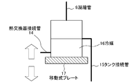
- the condensed refrigerant is conveyed to the uppermost tank 13 shown in FIG.
- the condensed refrigerant liquid carried to the tank 13 is supplied to the uppermost evaporator through the heat exchanger connecting pipe 14.
- the tank liquid level rises as the condensed refrigerant liquid continues to be supplied, but when the tank liquid level rises to the same height as the connection port of the tank connection pipe 15 connected to the tank 13, the solvent liquid Is not connected to the uppermost heat receiver but to the lower tank 13 through the tank connection pipe 15.
- the condensed solvent liquid is supplied to all the plurality of evaporators 4.
- the exhaust heat of the electronic device is discharged outside the data center 1 by the above cycle.
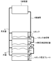
- FIG. 1 shows a cross-sectional view of a server rack 6 for storing a plurality of electronic devices and a data center 1 on which a plurality of server racks are mounted.
- FIG. 2 shows a top view of the data center 1.
- the data center 1 is provided with an intake port 2 for taking in outside air, an exhaust port 3 for discharging outside air, and a circulation FAN 10.
- a plurality of evaporators 4 whose interiors are filled with the refrigerant 16 are installed from the upper part to the lower part of the server rack 6.
- the evaporator 4 is preferably provided corresponding to each server rack.
- a plurality of server racks configured by vertically stacking a plurality of server racks are arranged horizontally.
- a cooling system shown in FIG. 3 is provided for each server rack.
- a temperature sensor 7 for measuring the exhaust temperature from the server is attached to the server side of the plurality of evaporators, and a temperature sensor 7 for measuring the air temperature after heat exchange is installed inside the data center 1 of the evaporator. Is attached.
- a low boiling point refrigerant 16 such as hydrofluorocarbon or hydrofluoroether is used.
- the evaporator 4 is connected to a condenser 5 in the condensing chamber 11 through a steam pipe 8 through which steam mainly passes to a condensing chamber 11 provided in the data center 1. Further, from the condenser 5, a condenser tube 9 through which the condensed liquid phase-changed from vapor to liquid in the condenser 5 passes to the evaporator 4, and the evaporator 4 and the condenser 5 are condensed to the vapor pipe 8. Connected through a tube 9.
- the evaporator 4 and the condenser 5 are both heat exchangers for exchanging heat between the air and the refrigerant 16, and for example, fin-and-tube heat exchangers are used.
- the condensing chamber 11 is provided with an intake port 2 and an exhaust port 3, and the condenser 5 is provided with a condensing FAN that promotes heat exchange between the refrigerant 16 and air. Yes.
- each evaporator is provided with a tank 13 for storing the refrigerant 16.
- the tank 13 of the uppermost evaporator 4 is connected to the condenser 5 shown in FIGS.
- Each tank 13 and the evaporator 4 are connected to the evaporator 4 through the heat exchanger connecting pipe 14, and the tanks 13 are connected to each other through the tank connecting pipe 15.
- the heat exchanger connection pipe 14 is preferably structured to move or expand and contract in response to the vertical movement of the tank described later. Further, as shown in FIG. 3, the vapor pipes 8 of the respective evaporators 4 are combined into one and connected to the condenser 5.
- Each tank 13 is installed and fixed on a movable plate 17 whose height can be changed in the vertical direction of the tank 13 as shown in FIG.
- the movable plate 17 moves up and down by converting the power of a driving machine such as a motor into a force in the vertical direction.
- the operation of this driving machine is controlled by a control unit (not shown). Based on the temperature information obtained from the temperature sensor 7, the control unit performs the vertical movement of the tank, which will be described later, and power control of the circulation fan 10.
- the control of the circulation fan using the temperature sensor 7 and the control of the cooling performance of the heat receiving part will be described.
- the server exhaust temperature rises. For example, when the exhaust temperature of the server becomes 40 ° C. or more, the intake air of the server directly takes in the exhaust due to the short return phenomenon that the exhaust of the server goes around the server rack 6 described above.
- the inlet air temperature of the server should be 40 ° C. or lower, and the operational reliability of the server will be impaired if this is left as it is. Therefore, when the temperature sensor 7 on the data center 1 side of the heat receiving unit becomes 40 ° C. or higher, the control unit raises the moving plate of the tank 13 to increase the cooling performance of the heat receiving unit with respect to the drive unit. The operation of raising the refrigerant height is performed.
- the control unit lowers the power of the circulating FAN 10 to facilitate the above-described short return.
- a short return occurs, the server inlet air temperature rises, but at the same time heat exchange is facilitated, so the rise in the server inlet air temperature is suppressed.
- This cooling performance can be expressed as a temperature difference ( ⁇ T) between the temperature sensor 7 on the server side and the temperature sensor 7 on the data center 1 side.
- ⁇ T temperature difference
- the control unit controls the reduction of the power of the circulating FAN 10 described above until the performance of the heat exchanger reaches the maximum value ⁇ T.
- the effect by the above-mentioned action is that the temperature of each server provided with an evaporator can be controlled because the ability of the individual evaporators can be controlled.
- the system does not become complicated because the temperature control is also an operation control that makes it easy to control the vertical movement of the tank.
- the second embodiment will be described with reference to the drawings.
- a structure that overlaps the first embodiment is omitted.
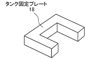
- the second embodiment is different from the first embodiment in that the mechanism for adjusting the liquid level of the tank 13 is not the movable plate 17 but the tank fixing plate 18 as shown in FIG. It is a point.
- a plurality of tank fixing plates 18 are connected to the side surface of the evaporator.
- the tank fixing plate 18 has a hollow cutout so that the tank 13 can be fixed.
- the liquid level height of the heat receiving part is adjusted by changing the mounting position of the tank 13 between the plurality of tank fixing plates 18 in the vertical direction.
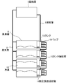
- the third embodiment is different from the first embodiment in that a mechanism for adjusting the liquid level of the tank 13 is performed by the fluid control valve 19 as shown in FIG.
- a plurality of fluid control fluid control valves 19 are installed in the tank 13 in the vertical direction of the tank 13.
- the uppermost fluid control fluid control valve 19 shown in FIG. 7 is opened and the remaining two fluid control valves 19 are closed, so that the liquid level height is increased.
- the condensate reaches the lower tank 13.
- the liquid level of the heat receiving portion is controlled by the control of the fluid control valve 19, not by the form of moving the plate 17 up and down.
- the control unit can automatically control the valve based on the temperature information from the temperature sensor.
- the valve may be adjusted by a human hand as in the second embodiment.
- the present invention relates to a cooling system for an electronic device storage device or the like, and more particularly to a cooling system for an electronic device storage device or the like that cools heat from a plurality of heat sources such as servers.
Abstract
Description
2 吸気口
3 排気口
4 蒸発器
5 凝縮器
6 サーバラック
7 温度センサ
8 蒸気管
9 凝縮管
10 循環FAN
11 凝縮室
12 凝縮FAN
13 タンク
14 熱交換器接続管
15 タンク接続管
16 冷媒
17 移動式プレート
18 タンク固定プレート
19 流体制御バルブ 1 Data center
2 Inlet
3 Exhaust port
4 Evaporator 5 Condenser
6 Server rack 7
11 Condensing chamber 12 Condensing FAN
13
Claims (8)
- 電子機器と、前記電子機器を載置する複数段の載置棚とで構成されるラックを備え、前記ラックには内部に冷媒を有する蒸発器が搭載され、前記ラックの外部には前記蒸発器と配管で接続された凝縮部が設置され、前記蒸発器内の冷媒面の高さを調整する冷媒調整手段を備えることを特徴とした電子機器収納装置の冷却システム。 A rack comprising an electronic device and a plurality of mounting shelves on which the electronic device is placed is mounted, and an evaporator having a refrigerant inside is mounted on the rack, and the evaporator is disposed outside the rack. A cooling system for an electronic device storage apparatus, comprising a condenser adjusting unit that adjusts a height of a refrigerant surface in the evaporator.
- 前記熱交換器の蒸発器には冷媒を貯蔵するタンクを備える請求項1に記載の電子機器収納装置の冷却システム。 The cooling system for an electronic device storage device according to claim 1, wherein the evaporator of the heat exchanger includes a tank for storing a refrigerant.
- 前記冷媒面の高さを調整する冷媒調整手段は、前記タンクの高さを調節する手段を有したことを特徴とする請求項2に記載の電子機器収納装置の冷却システム。 3. The cooling system for an electronic device storage device according to claim 2, wherein the refrigerant adjusting means for adjusting the height of the refrigerant surface has means for adjusting the height of the tank.
- 前記冷媒面の高さを調整する冷媒調整手段は、それぞれが前記凝縮部に接続し、かつ前記タンクの異なる高さに接続した複数の流体制御装置が設けられたことを特徴とする請求項2に記載の電子機器収納装置の冷却システム。 The refrigerant adjusting means for adjusting the height of the refrigerant surface is provided with a plurality of fluid control devices each connected to the condensing unit and connected to different heights of the tank. The cooling system of the electronic device storage apparatus described in 1.
- 前記ラックの温度を検知する温度センサを設け、その結果に応じて前記冷媒面の高さを調整する冷媒調整手段を制御することを特徴とする請求項1から4のいずれかに記載の電子機収納装置の温度調整システム。 5. The electronic device according to claim 1, further comprising: a temperature sensor that detects a temperature of the rack, and controlling a refrigerant adjusting unit that adjusts a height of the refrigerant surface according to a result of the temperature sensor. Storage device temperature control system.
- 電子機器と、前記電子機器を載置する複数段の載置棚とで構成されるラックを備え、前記ラックは前記ラックを複数台収納する建屋に配置され、前記建屋には外気を吸気、排気する複数個の吸気口、排気口が設けられ、前記ラックには内部に冷媒を有する蒸発器と、前記ラックの外部に前記蒸発器と配管で接続された凝縮部が設置され、前記蒸発器内の冷媒面の高さを調整する冷媒調整手段を備えることを特徴とする電子機器収納建屋の冷却システム。 A rack comprising an electronic device and a plurality of mounting shelves on which the electronic device is placed, the rack being disposed in a building that houses a plurality of the racks; A plurality of intake ports and exhaust ports are provided, an evaporator having a refrigerant inside is provided in the rack, and a condensing unit connected to the evaporator by a pipe is installed outside the rack. A cooling system for an electronic device housing building, comprising refrigerant adjusting means for adjusting the height of the refrigerant surface of the electronic device.
- 前記電子機器収納建屋の排気口には送風機が設置されていることを特徴とした請求項6に記載の電子機器収納建屋の冷却システム。 The cooling system for an electronic device storage building according to claim 6, wherein a blower is installed at an exhaust port of the electronic device storage building.
- 前記ラックの温度を検知する温度センサを設け、その結果に応じて前記電子機器収納建屋の送風機出力と、冷媒調整手段を制御することを特徴とした請求項6または7に記載の電子機器収納建屋の冷却システム。 The electronic device storage building according to claim 6 or 7, wherein a temperature sensor for detecting the temperature of the rack is provided, and a blower output of the electronic device storage building and a refrigerant adjusting means are controlled according to the result. Cooling system.
Priority Applications (9)
| Application Number | Priority Date | Filing Date | Title |
|---|---|---|---|
| KR1020157017796A KR20150091506A (en) | 2012-12-03 | 2013-12-03 | Cooling system for electronic equipment storage device and cooling system for electronic equipment storage facility |
| CN201380063005.2A CN104838329A (en) | 2012-12-03 | 2013-12-03 | Cooling system for electronic equipment storage device and cooling system for electronic equipment storage facility |
| SG11201504298TA SG11201504298TA (en) | 2012-12-03 | 2013-12-03 | Cooling system for electronic device storing apparatus and cooling system for electronic device storing building |
| US14/646,599 US9693485B2 (en) | 2012-12-03 | 2013-12-03 | Cooling system for electronic device storing apparatus and cooling system for electronic device storing building |
| EP13860412.9A EP2927778A4 (en) | 2012-12-03 | 2013-12-03 | Cooling system for electronic equipment storage device and cooling system for electronic equipment storage facility |
| JP2014550921A JPWO2014087635A1 (en) | 2012-12-03 | 2013-12-03 | Cooling system for electronic device storage device and cooling system for electronic device storage building |
| IN3895DEN2015 IN2015DN03895A (en) | 2012-12-03 | 2013-12-03 | |
| AU2013356152A AU2013356152B2 (en) | 2012-12-03 | 2013-12-03 | Cooling system for electronic device storing apparatus and cooling system for electronic device storing building |
| BR112015012796A BR112015012796A2 (en) | 2012-12-03 | 2013-12-03 | electronic storage device cooling system and electronic storage device cooling system |
Applications Claiming Priority (2)
| Application Number | Priority Date | Filing Date | Title |
|---|---|---|---|
| JP2012-264430 | 2012-12-03 | ||
| JP2012264430 | 2012-12-03 |
Publications (1)
| Publication Number | Publication Date |
|---|---|
| WO2014087635A1 true WO2014087635A1 (en) | 2014-06-12 |
Family
ID=50883077
Family Applications (1)
| Application Number | Title | Priority Date | Filing Date |
|---|---|---|---|
| PCT/JP2013/007069 WO2014087635A1 (en) | 2012-12-03 | 2013-12-03 | Cooling system for electronic equipment storage device and cooling system for electronic equipment storage facility |
Country Status (10)
| Country | Link |
|---|---|
| US (1) | US9693485B2 (en) |
| EP (1) | EP2927778A4 (en) |
| JP (1) | JPWO2014087635A1 (en) |
| KR (1) | KR20150091506A (en) |
| CN (1) | CN104838329A (en) |
| AU (1) | AU2013356152B2 (en) |
| BR (1) | BR112015012796A2 (en) |
| IN (1) | IN2015DN03895A (en) |
| SG (1) | SG11201504298TA (en) |
| WO (1) | WO2014087635A1 (en) |
Cited By (7)
| Publication number | Priority date | Publication date | Assignee | Title |
|---|---|---|---|---|
| WO2016048616A1 (en) * | 2014-09-23 | 2016-03-31 | Google Inc. | Cooling electronic devices in a data center |
| WO2016147615A1 (en) * | 2015-03-13 | 2016-09-22 | 日本電気株式会社 | Refrigerant supply device, phase change cooling device in which same is used, and refrigerant supply method |
| CN106304752A (en) * | 2015-05-19 | 2017-01-04 | 王玉富 | A kind of phase-change heat-exchange rack being applicable to server hierarchies configuration |
| WO2017133055A1 (en) * | 2015-02-06 | 2017-08-10 | 深圳易信科技股份有限公司 | Emergency refrigerating device for machine room |
| EP3214390A4 (en) * | 2014-10-17 | 2018-08-01 | NEC Platforms, Ltd. | Refrigerant supply device, cooling device, and cooling system |
| WO2019054456A1 (en) * | 2017-09-13 | 2019-03-21 | 株式会社デンソー | Thermo-siphon |
| US10349561B2 (en) | 2016-04-15 | 2019-07-09 | Google Llc | Cooling electronic devices in a data center |
Families Citing this family (13)
| Publication number | Priority date | Publication date | Assignee | Title |
|---|---|---|---|---|
| WO2016031186A1 (en) * | 2014-08-27 | 2016-03-03 | 日本電気株式会社 | Phase-change cooling device, and phase-change cooling method |
| US10448543B2 (en) * | 2015-05-04 | 2019-10-15 | Google Llc | Cooling electronic devices in a data center |
| CN108141990B (en) * | 2015-10-21 | 2020-03-20 | 维谛公司 | Cooling system for small equipment room and method for cooling small equipment room |
| CN105910600A (en) * | 2016-06-14 | 2016-08-31 | 冯青元 | Micro-region navigation system and method |
| CN105919301B (en) * | 2016-06-17 | 2018-02-06 | 胡江 | Rice-storing cabinet and its control method based on Internet of Things |
| JP6304420B1 (en) * | 2017-03-23 | 2018-04-04 | 日本電気株式会社 | Refrigerant distribution device, cooling device, and refrigerant distribution method in refrigerant distribution device |
| US11359865B2 (en) * | 2018-07-23 | 2022-06-14 | Green Revolution Cooling, Inc. | Dual Cooling Tower Time Share Water Treatment System |
| KR101995512B1 (en) * | 2019-03-22 | 2019-07-02 | 엘제이테크 주식회사 | Coller for industrial apparatus |
| USD982145S1 (en) | 2020-10-19 | 2023-03-28 | Green Revolution Cooling, Inc. | Cooling system enclosure |
| USD998770S1 (en) | 2020-10-19 | 2023-09-12 | Green Revolution Cooling, Inc. | Cooling system enclosure |
| US11812587B2 (en) * | 2021-05-03 | 2023-11-07 | Microsoft Technology Licensing, Llc | Computer cooling |
| US11805624B2 (en) | 2021-09-17 | 2023-10-31 | Green Revolution Cooling, Inc. | Coolant shroud |
| US11925946B2 (en) | 2022-03-28 | 2024-03-12 | Green Revolution Cooling, Inc. | Fluid delivery wand |
Citations (5)
| Publication number | Priority date | Publication date | Assignee | Title |
|---|---|---|---|---|
| JPH05312361A (en) * | 1991-11-20 | 1993-11-22 | Furukawa Electric Co Ltd:The | Air-conditioning system |
| JP2011226737A (en) | 2010-04-22 | 2011-11-10 | Sanki Eng Co Ltd | Air conditioning system for data center |
| WO2012029404A1 (en) * | 2010-08-31 | 2012-03-08 | 日本電気株式会社 | System for cooling electronic device |
| JP2012199300A (en) * | 2011-03-18 | 2012-10-18 | Shimizu Corp | Unit type data center |
| JP2013065227A (en) * | 2011-09-20 | 2013-04-11 | Hitachi Ltd | Cooling system for server rack and server apparatus |
Family Cites Families (17)
| Publication number | Priority date | Publication date | Assignee | Title |
|---|---|---|---|---|
| EP0281762B1 (en) | 1987-03-12 | 1992-06-17 | Takenaka Komuten Co. Ltd. | Air conditioning system for buildings |
| JPS643447A (en) * | 1987-03-12 | 1989-01-09 | Takenaka Komuten Co | Cooling system |
| JPH02259312A (en) * | 1989-03-31 | 1990-10-22 | Nippon Steel Corp | Combustion control method and device for liquid fuel |
| JP2002199300A (en) * | 2000-12-26 | 2002-07-12 | Matsushita Electric Ind Co Ltd | Image data transmission method, display method and image data transmitter |
| US6351381B1 (en) | 2001-06-20 | 2002-02-26 | Thermal Corp. | Heat management system |
| JP4018384B2 (en) * | 2001-12-25 | 2007-12-05 | 株式会社ブリヂストン | Steel wire oil applicator |
| US6881142B1 (en) * | 2003-09-12 | 2005-04-19 | Degree C | Intelligent networked fan assisted tiles for adaptive thermal management of thermally sensitive rooms |
| US7270174B2 (en) * | 2003-12-16 | 2007-09-18 | International Business Machines Corporation | Method, system and program product for automatically checking coolant loops of a cooling system for a computing environment |
| US7963118B2 (en) * | 2007-09-25 | 2011-06-21 | International Business Machines Corporation | Vapor-compression heat exchange system with evaporator coil mounted to outlet door of an electronics rack |
| JP2011224863A (en) * | 2010-04-20 | 2011-11-10 | Seiko Epson Corp | Apparatus and method for forming film |
| US9038406B2 (en) * | 2010-05-26 | 2015-05-26 | International Business Machines Corporation | Dehumidifying cooling apparatus and method for an electronics rack |
| JP5351097B2 (en) * | 2010-06-18 | 2013-11-27 | 株式会社日立製作所 | Refrigerant circulation device |
| US8351206B2 (en) * | 2010-06-29 | 2013-01-08 | International Business Machines Corporation | Liquid-cooled electronics rack with immersion-cooled electronic subsystems and vertically-mounted, vapor-condensing unit |
| CN102143671A (en) * | 2010-09-13 | 2011-08-03 | 华为技术有限公司 | Radiating method and device |
| CN102736706B (en) * | 2011-04-13 | 2015-07-01 | 英业达股份有限公司 | Rack system of server |
| CA2863198C (en) * | 2012-02-14 | 2018-08-14 | Nec Corporation | Cooling apparatus and cooling system |
| US9638583B2 (en) * | 2014-05-21 | 2017-05-02 | Amazon Technologies, Inc. | Virtual data center environmental monitoring system |
-
2013
- 2013-12-03 IN IN3895DEN2015 patent/IN2015DN03895A/en unknown
- 2013-12-03 AU AU2013356152A patent/AU2013356152B2/en not_active Expired - Fee Related
- 2013-12-03 US US14/646,599 patent/US9693485B2/en not_active Expired - Fee Related
- 2013-12-03 CN CN201380063005.2A patent/CN104838329A/en active Pending
- 2013-12-03 SG SG11201504298TA patent/SG11201504298TA/en unknown
- 2013-12-03 EP EP13860412.9A patent/EP2927778A4/en not_active Withdrawn
- 2013-12-03 JP JP2014550921A patent/JPWO2014087635A1/en active Pending
- 2013-12-03 KR KR1020157017796A patent/KR20150091506A/en not_active Application Discontinuation
- 2013-12-03 WO PCT/JP2013/007069 patent/WO2014087635A1/en active Application Filing
- 2013-12-03 BR BR112015012796A patent/BR112015012796A2/en not_active IP Right Cessation
Patent Citations (5)
| Publication number | Priority date | Publication date | Assignee | Title |
|---|---|---|---|---|
| JPH05312361A (en) * | 1991-11-20 | 1993-11-22 | Furukawa Electric Co Ltd:The | Air-conditioning system |
| JP2011226737A (en) | 2010-04-22 | 2011-11-10 | Sanki Eng Co Ltd | Air conditioning system for data center |
| WO2012029404A1 (en) * | 2010-08-31 | 2012-03-08 | 日本電気株式会社 | System for cooling electronic device |
| JP2012199300A (en) * | 2011-03-18 | 2012-10-18 | Shimizu Corp | Unit type data center |
| JP2013065227A (en) * | 2011-09-20 | 2013-04-11 | Hitachi Ltd | Cooling system for server rack and server apparatus |
Cited By (18)
| Publication number | Priority date | Publication date | Assignee | Title |
|---|---|---|---|---|
| CN106489308B (en) * | 2014-09-23 | 2018-07-13 | 谷歌有限责任公司 | Electronic device in cooling data center |
| US9961803B2 (en) | 2014-09-23 | 2018-05-01 | Google Llc | Cooling electronic devices in a data center |
| WO2016048616A1 (en) * | 2014-09-23 | 2016-03-31 | Google Inc. | Cooling electronic devices in a data center |
| GB2545106B (en) * | 2014-09-23 | 2018-08-22 | Google Llc | Cooling electronic devices in a data center |
| CN106489308A (en) * | 2014-09-23 | 2017-03-08 | 谷歌公司 | Electronic installation in cooling data center |
| GB2545106A (en) * | 2014-09-23 | 2017-06-07 | Google Inc | Cooling electronic devices in a data center |
| CN108770297A (en) * | 2014-09-23 | 2018-11-06 | 谷歌有限责任公司 | Electronic device in cooling data center |
| US10542641B2 (en) | 2014-09-23 | 2020-01-21 | Google Llc | Cooling electronic devices in a data center |
| CN108770297B (en) * | 2014-09-23 | 2021-01-12 | 谷歌有限责任公司 | Cooling electronic devices in a data center |
| US9552025B2 (en) | 2014-09-23 | 2017-01-24 | Google Inc. | Cooling electronic devices in a data center |
| US10149412B2 (en) | 2014-10-17 | 2018-12-04 | Nec Platforms, Ltd | Refrigerant supply device, cooling device, and cooling system |
| EP3214390A4 (en) * | 2014-10-17 | 2018-08-01 | NEC Platforms, Ltd. | Refrigerant supply device, cooling device, and cooling system |
| WO2017133055A1 (en) * | 2015-02-06 | 2017-08-10 | 深圳易信科技股份有限公司 | Emergency refrigerating device for machine room |
| WO2016147615A1 (en) * | 2015-03-13 | 2016-09-22 | 日本電気株式会社 | Refrigerant supply device, phase change cooling device in which same is used, and refrigerant supply method |
| CN106304752A (en) * | 2015-05-19 | 2017-01-04 | 王玉富 | A kind of phase-change heat-exchange rack being applicable to server hierarchies configuration |
| US10349561B2 (en) | 2016-04-15 | 2019-07-09 | Google Llc | Cooling electronic devices in a data center |
| JP2019052787A (en) * | 2017-09-13 | 2019-04-04 | 株式会社デンソー | Thermosiphon |
| WO2019054456A1 (en) * | 2017-09-13 | 2019-03-21 | 株式会社デンソー | Thermo-siphon |
Also Published As
| Publication number | Publication date |
|---|---|
| EP2927778A1 (en) | 2015-10-07 |
| US9693485B2 (en) | 2017-06-27 |
| CN104838329A (en) | 2015-08-12 |
| US20150305209A1 (en) | 2015-10-22 |
| AU2013356152B2 (en) | 2017-07-27 |
| BR112015012796A2 (en) | 2017-07-11 |
| KR20150091506A (en) | 2015-08-11 |
| SG11201504298TA (en) | 2015-07-30 |
| EP2927778A4 (en) | 2016-08-03 |
| AU2013356152A1 (en) | 2015-05-28 |
| IN2015DN03895A (en) | 2015-10-02 |
| JPWO2014087635A1 (en) | 2017-01-05 |
Similar Documents
| Publication | Publication Date | Title |
|---|---|---|
| WO2014087635A1 (en) | Cooling system for electronic equipment storage device and cooling system for electronic equipment storage facility | |
| JP5902053B2 (en) | Cooling system and cooling method | |
| JP5024675B2 (en) | Electronic device cooling system and cooling method | |
| US9459031B2 (en) | Cooling apparatus and cooling system | |
| JP2012007865A (en) | Cooling system | |
| WO2011122207A1 (en) | Cooling apparatus and cooling system for electronic-device exhaustion | |
| JP2009216295A (en) | Cooling system of electronic device and its operating method | |
| JP5676966B2 (en) | Cooling system | |
| JP5041342B2 (en) | Electronic equipment cooling system | |
| JP5745337B2 (en) | Air conditioning system | |
| JP5831467B2 (en) | Heating system | |
| US20200281099A1 (en) | Heat extraction system for a computing equipment enclosure | |
| CN111988973A (en) | Air-cooled heat dissipation equipment and cooling system | |
| US9360224B2 (en) | Air condition system | |
| JP6174386B2 (en) | Dehumidification control method for air conditioning system | |
| EP3358923B1 (en) | Cooling system with reduced pressure drop | |
| JP5619698B2 (en) | Geothermal heat pump device | |
| JP2015200433A (en) | Natural circulation type cooling system and control method | |
| CN209882438U (en) | Integral type server rack heat pipe air conditioner | |
| TW201135431A (en) | Data center cooling | |
| WO2014042151A1 (en) | Air-conditioning control system | |
| JP2005282988A (en) | Cooling device | |
| JP2010205962A (en) | Electronic equipment cooling device | |
| JP2012059276A (en) | Cooling system for electronic apparatus | |
| JP2010236737A (en) | Heat pump device |
Legal Events
| Date | Code | Title | Description |
|---|---|---|---|
| 121 | Ep: the epo has been informed by wipo that ep was designated in this application |
Ref document number: 13860412 Country of ref document: EP Kind code of ref document: A1 |
|
| REEP | Request for entry into the european phase |
Ref document number: 2013860412 Country of ref document: EP |
|
| WWE | Wipo information: entry into national phase |
Ref document number: 2013860412 Country of ref document: EP |
|
| ENP | Entry into the national phase |
Ref document number: 2014550921 Country of ref document: JP Kind code of ref document: A |
|
| WWE | Wipo information: entry into national phase |
Ref document number: 14646599 Country of ref document: US |
|
| ENP | Entry into the national phase |
Ref document number: 2013356152 Country of ref document: AU Date of ref document: 20131203 Kind code of ref document: A |
|
| NENP | Non-entry into the national phase |
Ref country code: DE |
|
| REG | Reference to national code |
Ref country code: BR Ref legal event code: B01A Ref document number: 112015012796 Country of ref document: BR |
|
| ENP | Entry into the national phase |
Ref document number: 20157017796 Country of ref document: KR Kind code of ref document: A |
|
| ENP | Entry into the national phase |
Ref document number: 112015012796 Country of ref document: BR Kind code of ref document: A2 Effective date: 20150602 |