WO2014087516A1 - Method for producing steel sheet - Google Patents
Method for producing steel sheet Download PDFInfo
- Publication number
- WO2014087516A1 WO2014087516A1 PCT/JP2012/081634 JP2012081634W WO2014087516A1 WO 2014087516 A1 WO2014087516 A1 WO 2014087516A1 JP 2012081634 W JP2012081634 W JP 2012081634W WO 2014087516 A1 WO2014087516 A1 WO 2014087516A1
- Authority
- WO
- WIPO (PCT)
- Prior art keywords
- steel sheet
- hot
- rolled steel
- cooling
- temperature
- Prior art date
Links
Images


Classifications
-
- B—PERFORMING OPERATIONS; TRANSPORTING
- B21—MECHANICAL METAL-WORKING WITHOUT ESSENTIALLY REMOVING MATERIAL; PUNCHING METAL
- B21B—ROLLING OF METAL
- B21B1/00—Metal-rolling methods or mills for making semi-finished products of solid or profiled cross-section; Sequence of operations in milling trains; Layout of rolling-mill plant, e.g. grouping of stands; Succession of passes or of sectional pass alternations
- B21B1/22—Metal-rolling methods or mills for making semi-finished products of solid or profiled cross-section; Sequence of operations in milling trains; Layout of rolling-mill plant, e.g. grouping of stands; Succession of passes or of sectional pass alternations for rolling plates, strips, bands or sheets of indefinite length
- B21B1/24—Metal-rolling methods or mills for making semi-finished products of solid or profiled cross-section; Sequence of operations in milling trains; Layout of rolling-mill plant, e.g. grouping of stands; Succession of passes or of sectional pass alternations for rolling plates, strips, bands or sheets of indefinite length in a continuous or semi-continuous process
- B21B1/26—Metal-rolling methods or mills for making semi-finished products of solid or profiled cross-section; Sequence of operations in milling trains; Layout of rolling-mill plant, e.g. grouping of stands; Succession of passes or of sectional pass alternations for rolling plates, strips, bands or sheets of indefinite length in a continuous or semi-continuous process by hot-rolling, e.g. Steckel hot mill
-
- B—PERFORMING OPERATIONS; TRANSPORTING
- B21—MECHANICAL METAL-WORKING WITHOUT ESSENTIALLY REMOVING MATERIAL; PUNCHING METAL
- B21B—ROLLING OF METAL
- B21B37/00—Control devices or methods specially adapted for metal-rolling mills or the work produced thereby
- B21B37/28—Control of flatness or profile during rolling of strip, sheets or plates
-
- B—PERFORMING OPERATIONS; TRANSPORTING
- B21—MECHANICAL METAL-WORKING WITHOUT ESSENTIALLY REMOVING MATERIAL; PUNCHING METAL
- B21B—ROLLING OF METAL
- B21B37/00—Control devices or methods specially adapted for metal-rolling mills or the work produced thereby
- B21B37/16—Control of thickness, width, diameter or other transverse dimensions
-
- B—PERFORMING OPERATIONS; TRANSPORTING
- B21—MECHANICAL METAL-WORKING WITHOUT ESSENTIALLY REMOVING MATERIAL; PUNCHING METAL
- B21B—ROLLING OF METAL
- B21B37/00—Control devices or methods specially adapted for metal-rolling mills or the work produced thereby
- B21B37/74—Temperature control, e.g. by cooling or heating the rolls or the product
- B21B37/76—Cooling control on the run-out table
Definitions
- the present invention relates to a steel plate manufacturing method.
- FIG. 19 is a diagram schematically showing a conventional method for producing a hot-rolled steel sheet.
- a slab S obtained by continuously casting a molten steel adjusted to a predetermined composition is rolled with a roughing mill 101, and then finished with a plurality of rolling stands 102a to 102d.
- Hot rolling is performed by the rolling mill 103 to form a hot-rolled steel sheet H having a predetermined thickness.
- this hot-rolled steel sheet H is cooled by the cooling water poured from the cooling device 111, it is wound up by the winding device 112 in a coil shape.
- the cooling device 111 is a facility for performing so-called laminar cooling on the hot-rolled steel sheet H that is generally conveyed from the finish rolling mill 103.
- the cooling device 111 injects cooling water as jet water from above in the vertical direction to the upper surface of the hot-rolled steel sheet H moving on the run-out table, and also to the lower surface of the hot-rolled steel sheet H. Then, the hot-rolled steel sheet H is cooled by injecting cooling water as jet water through the pipe laminator.
- Patent Document 1 discloses a technique for preventing a shape defect of a steel plate by reducing a difference in surface temperature between the upper and lower surfaces of the thick steel plate. According to the technique disclosed in Patent Document 1, based on the surface temperature difference obtained by simultaneously measuring the surface temperature of the upper and lower surfaces of the steel sheet with a thermometer during cooling by the cooling device, the upper and lower surfaces of the steel sheet Adjust the ratio of the amount of cooling water supplied to the.
- Patent Document 2 a steepness meter installed on the exit side of a rolling mill is used to measure the steepness of the steel sheet tip, and the cooling water flow rate is adjusted in the width direction according to the measured steepness.
- a technique for preventing perforation of a steel sheet is disclosed.
- the object is to eliminate the wavy plate thickness distribution in the plate width direction of the hot-rolled steel plate, and to uniformize the plate thickness in the plate width direction, in the plate width direction of the hot-rolled steel plate.
- a technique for controlling the difference between the maximum heat transfer coefficient and the minimum heat transfer coefficient to fall within a predetermined value range is disclosed.
- Japanese Unexamined Patent Publication No. 2005-74463 Japanese Patent Application Laid-Open No. 2005-271052 Japanese Unexamined Patent Publication No. 2003-48003
- the hot-rolled steel sheet H manufactured by the conventional manufacturing method described with reference to FIG. 19 is, for example, as shown in FIG. 20, a run-out table (hereinafter, referred to as “ROT”) in the cooling device 111.
- ROT run-out table
- the material that is, the hardness of the steel plate
- the temperature unevenness varies due to the temperature unevenness.
- Patent Document 1 does not consider the case where the hot-rolled steel sheet has a wave shape in the rolling direction. That is, in patent document 1, since surface height changes with the wave positions of a hot-rolled steel plate, it does not consider that the standard deviation of temperature differs in a rolling direction. Therefore, in the cooling method of patent document 1, it was not considered that the variation of a material generate
- Patent Document 3 since the cooling of Patent Document 3 is the cooling of a hot-rolled steel sheet immediately before a finish rolling mill roll bite, it cannot be applied to a hot-rolled steel sheet having a predetermined thickness after finish rolling. Furthermore, Patent Document 3 does not consider the case where the corrugation is formed in the rolling direction of the hot-rolled steel sheet, and as described above, due to the corrugation formed on the hot-rolled steel sheet, The occurrence of material variations was not taken into account.
- the present invention has been made in view of the above-described problems, and an object of the present invention is to provide a steel sheet manufacturing method capable of improving the yield of a steel sheet manufactured through at least a hot rolling process and a cooling process.
- a method of manufacturing a steel sheet according to an aspect of the present invention includes a hot-rolled steel sheet in which an ear-wave shape whose wave height varies periodically in the rolling direction is formed by hot-rolling a steel material with a finish rolling mill.
- a hot rolling step to obtain; and a cooling step for cooling the hot-rolled steel sheet in a cooling section provided on the sheet passing path, and the hot rolling step has been experimentally obtained in advance.
- the target steepness of the ear-wave shape Based on the first correlation data showing the correlation between the steepness of the ear-wave shape of the hot-rolled steel plate and the temperature standard deviation Y during or after cooling of the hot-rolled steel plate, the target steepness of the ear-wave shape And a shape control step for controlling the operating parameters of the finishing mill so that the steepness of the ear wave shape matches the target steepness.
- the target steepness in the target steepness setting step, may be set to more than 0% and within 1%.
- the cooling step is experimentally determined in advance under a condition in which the steepness and the sheet passing speed of the hot-rolled steel sheet are constant values.
- the second correlation showing the correlation between the upper and lower heat transfer coefficient ratio X, which is the ratio of the heat transfer coefficients of the upper and lower surfaces of the hot rolled steel sheet, and the temperature standard deviation Y during or after cooling the hot rolled steel sheet
- a cooling control step of controlling at least one of the upper surface cooling heat removal amount and the lower surface cooling heat removal amount of the hot-rolled steel sheet in the cooling section so as to coincide with the target ratio Xt.
- the temperature standard deviation Y is within a range from the minimum value Ymin to the minimum value Ymin + 10 ° C. based on the second correlation data.
- the upper and lower heat transfer coefficient ratio X that fits may be set as the target ratio Xt.
- the second correlation data is prepared for each of a plurality of conditions having different values of the steepness and the plate passing speed
- the target ratio setting In the step, the target ratio Xt may be set based on second correlation data corresponding to the measured values of the steepness and the plate passing speed among the plurality of second correlation data.
- the second correlation data may be data indicating a correlation between the upper and lower heat transfer coefficient ratio X and the temperature standard deviation Y by a regression equation. good.
- the regression equation may be derived by linear regression.
- the second correlation data may be data indicating a correlation between the upper and lower heat transfer coefficient ratio X and the temperature standard deviation Y in a table. .
- a cooling heat removal amount adjustment step of adjusting a total value with the heat removal amount.
- the cooling section is divided into a plurality of divided cooling sections along a plate-passing direction of the hot-rolled steel sheet, and the temperature measurement step and the fluctuation speed are divided.
- the measurement step the temperature and the fluctuation rate of the hot-rolled steel sheet are measured in time series at each boundary of the divided cooling section, and in the control direction determining step, the hot-rolled steel sheet at each boundary of the divided cooling section Based on the measurement results of the temperature and the fluctuation rate of the above, the direction of increase or decrease of the cooling heat removal amount of the upper and lower surfaces of the hot-rolled steel sheet is determined for each of the divided cooling sections, and in the cooling heat removal amount adjustment step, Based on the control direction determined for each, at least one of the upper surface cooling heat removal amount and the lower surface cooling heat removal amount of the hot-rolled steel sheet in each of the divided cooling sections. It may be performed feedback control or feed forward control to adjust the.
- the sheet passing speed of the hot-rolled steel sheet in the cooling section may be set in a range from 550 m / min or more to a mechanical limit speed or less.
- the hot-rolled steel sheet may have a tensile strength of 800 MPa or more.
- the finish rolling mill is configured by a plurality of rolling stands, and auxiliary cooling is performed to perform auxiliary cooling of the hot-rolled steel sheets between the plurality of rolling stands. You may have the process further.
- the cooling section includes an upper cooling device having a plurality of headers for injecting cooling water onto the upper surface of the hot-rolled steel plate, and a lower surface of the hot-rolled steel plate.
- a lower cooling device having a plurality of headers for injecting cooling water is provided, and the upper surface cooling heat removal amount and the lower surface cooling heat removal amount may be adjusted by on / off controlling the headers.
- the cooling section includes an upper cooling device having a plurality of headers for injecting cooling water onto the upper surface of the hot-rolled steel plate, and a lower surface of the hot-rolled steel plate.
- a lower cooling device having a plurality of headers for injecting cooling water, wherein the upper surface cooling heat removal amount and the lower surface cooling heat removal amount control at least one of the water amount density, pressure and water temperature of each header. It may be adjusted by doing.
- the cooling in the cooling section may be performed in a range where the temperature of the hot-rolled steel sheet is 600 ° C. or higher.
- the inventor of the present application conducted an extensive investigation on the relationship between the wave shape formed on the hot-rolled steel sheet obtained from the hot rolling process and the temperature standard deviation during or after cooling the hot-rolled steel sheet. It has been found that when the wave shape is controlled to an ear wave shape, the temperature standard deviation of the hot-rolled steel sheet can be controlled to an arbitrary value according to the steepness of the ear wave shape. That is, according to the present invention, in the hot rolling process, the experimentally obtained in advance the steepness of the ear wave shape of the hot-rolled steel sheet and the temperature standard deviation Y during or after cooling of the hot-rolled steel sheet.
- the target steepness of the ear wave shape is set, and finish rolling is performed so that the steepness of the ear wave shape formed on the hot-rolled steel sheet matches the target steepness.
- the temperature standard deviation of the hot-rolled steel sheet after cooling can be kept small (the hot-rolled steel sheet can be uniformly cooled).
- the yield can be improved by suppressing fluctuations in the thickness of the steel sheet finally obtained through the cold rolling process, which is a subsequent process. Can be realized.
- FIG. 1 shows the hot rolling equipment 1 for implement
- It is explanatory drawing which shows the outline of a structure of the cooling device 14 provided in the hot rolling equipment 1.
- FIG. It is explanatory drawing which shows a mode that the lowest point of the hot-rolled steel plate H contacts the conveyance roll 32.
- FIG. It is a graph which shows the temperature fluctuation in each location of the hot-rolled steel sheet H when the medium-wave shape with a steepness of 1% is formed on the hot-rolled steel sheet H and when the ear wave shape with a steepness of 1% is formed. .
- Cold rolling gauge fluctuation in the cold rolling process which is a subsequent process, when a medium wave shape with a steepness of 1% is formed on the hot-rolled steel sheet H and when an ear wave shape with a steepness of 1% is formed
- a graph showing the relationship between the temperature fluctuation and steepness of a hot-rolled steel sheet H in the ROT cooling of a typical strip in a normal operation shows the upper graph shows the temperature fluctuation with respect to the distance from the coil tip or the fixed point elapsed time.
- the lower graph shows the steepness with respect to the distance from the coil tip or the fixed point elapsed time. It is a graph which shows the relationship between the temperature fluctuation and the steepness of the hot-rolled steel sheet H in the ROT cooling of a typical strip in a normal operation.
- FIG. 6 is a graph showing the relationship between the temperature fluctuation and steepness of the hot-rolled steel sheet H when the upper surface cooling heat removal amount is decreased and the lower surface cooling heat removal amount is increased.
- the steepness of the wave shape of the hot-rolled steel sheet H is a value obtained by dividing the amplitude of the wave shape by the length in the rolling direction for one cycle.
- FIG. It is explanatory drawing which shows the detail of the periphery of the cooling device 14 in the hot rolling equipment 1.
- FIG. It is explanatory drawing which shows the modification of the cooling device. It is explanatory drawing which shows a mode that the temperature standard deviation was formed in the plate width direction of the hot-rolled steel plate H. It is explanatory drawing which shows the manufacturing method of the conventional hot-rolled steel plate H. It is explanatory drawing which shows the cooling method of the conventional hot-rolled steel plate H.
- FIG. 1 schematically shows an example of a hot rolling facility 1 for realizing the steel sheet manufacturing method in the present embodiment.
- This hot rolling facility 1 manufactures a steel plate (hot rolled steel plate H described later) having a minimum thickness of 1.2 mm by continuously rolling the heated slab S sandwiched between rolls, It is equipment intended to wind up steel plates.
- This hot rolling equipment 1 is rolled in the width direction, a heating furnace 11 for heating the slab S, a width-direction rolling mill 16 that rolls the slab S heated in the heating furnace 11 in the width direction, and the width direction.
- a roughing mill 12 that rolls the slab S from above and below to form a rough bar Br, and a steel plate having a predetermined thickness (hereinafter referred to as a hot-rolled steel plate) by continuously hot-rolling the rough bar Br. )
- Finish rolling mill 13 for forming H cooling device 14 for cooling hot-rolled steel sheet H conveyed from finishing mill 13 with cooling water, and hot-rolled steel sheet H cooled by cooling device 14 in a coil shape And a winding device 15 for winding.
- the heating furnace 11 is provided with a side burner, an axial flow burner, and a roof burner for heating the slab S by blowing out flames to the slab S carried in from the outside through the loading port.
- the slab S carried into the heating furnace 11 is sequentially heated in each heating zone formed in each zone, and further in the soaking zone formed in the final zone, the slab S is evenly heated using a roof burner, A coercive heat treatment is performed to enable conveyance at the optimum temperature.
- the slab S is transferred to the outside of the heating furnace 11 and moves to a rolling process by the roughing mill 12.
- the rough rolling mill 12 allows the slab S that has been conveyed to pass through a gap between cylindrical rotary rolls that are disposed across a plurality of stands.
- the roughing mill 12 hot-rolls the slab S only with the work rolls 12a disposed up and down in the first stand to form the rough bar Br.
- the rough bar Br that has passed through the first stand is further continuously rolled by a plurality of quadruple rolling mills 12b configured by work rolls and backup rolls.
- the rough bar Br is rolled to a thickness of about 30 to 60 mm and conveyed to the finishing mill 13.
- the finishing mill 13 hot finish-rolls the rough bar Br conveyed from the roughing mill 12 until its thickness reaches about several mm. These finishing mills 13 allow the rough bar Br to pass through the gap between the finish rolling rolls 13a arranged in a straight line over 6 to 7 stands, and gradually reduce this to obtain a predetermined plate thickness.
- the hot-rolled steel sheet H is formed.
- the hot-rolled steel sheet H formed by the finish rolling mill 13 is conveyed to the cooling device 14 by a conveyance roll 32 described later.
- the finish rolling mill 13 forms an ear wave shape in the rolling direction of the hot-rolled steel sheet H.
- the cooling device 14 is a facility for cooling the hot-rolled steel sheet H conveyed from the finish rolling mill 13 with a laminator or a spray. As shown in FIG. 2, the cooling device 14 has an upper cooling device 14 a that jets cooling water from the upper cooling port 31 to the upper surface of the hot-rolled steel sheet H that moves on the transport roll 32 of the run-out table, The lower side cooling device 14b which injects a cooling water from the lower side cooling port 31 with respect to the lower surface of the hot-rolled steel plate H is provided. A plurality of cooling ports 31 are provided for each of the upper cooling device 14a and the lower cooling device 14b. A cooling header (not shown) is connected to the cooling port 31.
- the cooling capacity of the upper cooling device 14a and the lower cooling device 14b is determined by the number of the cooling ports 31.
- the cooling device 14 may be composed of at least one of an upper / lower split laminar, a pipe laminar, spray cooling, and the like. Further, a section in which the hot-rolled steel sheet H is cooled by the cooling device 14 corresponds to a cooling section in the present invention.
- the winding device 15 winds the cooled hot-rolled steel sheet H conveyed from the cooling device 14 at a predetermined winding temperature.
- the hot-rolled steel sheet H wound in a coil shape by the winding device 15 is sent to a cold rolling facility (not shown) and cold-rolled to prepare a steel sheet that satisfies the specifications as a final product.
- the hot-rolled steel sheet H in which a corrugated shape whose surface height (wave height) fluctuates in the rolling direction is formed is performed, As described above, the hot-rolled steel sheet H can be made uniform by suitably adjusting the water volume density, pressure, water temperature, etc. of the cooling water injected from the upper cooling device 14a and the cooling water injected from the lower cooling device 14b. Cooling takes place. However, especially when the sheet passing speed is slow, the time for which the hot-rolled steel sheet H and the transport roll 32 are in local contact with each other becomes longer, and the contact portion of the hot-rolled steel sheet H with the transport roll 32 is cooled by contact heat removal. Since it becomes easy to be done, cooling will become non-uniform
- the hot-rolled steel sheet H may locally contact the transport roll 32 at the bottom of the corrugated shape.
- the part that is locally in contact with the transport roll 32 is more easily cooled than the other part by contact heat removal. For this reason, the hot-rolled steel sheet H is cooled unevenly.
- the hot rolling facility 1 when the hot-rolled steel sheet H is not uniformly cooled due to the wave shape being formed in the hot-rolled steel sheet H, the heat after cooling is reduced.
- the material (hardness etc.) of the rolled steel sheet H varies.
- a plate thickness variation occurs in the steel sheet (product steel sheet) finally obtained as a product. Since the plate thickness fluctuation of the product steel plate causes a decrease in yield, it is necessary to suppress it to a level at which it is not determined as a defective product in the inspection process. Therefore, the inventors of the present application conducted verification described below in order to examine the relationship between the wave shape formed in the hot-rolled steel sheet H and the thickness variation in the subsequent process (cold rolling process).
- FIG. 4 shows temperature fluctuations at various points of the hot-rolled steel sheet H when the hot-rolled steel sheet H has a medium-wave shape with a steepness of 1% and when an oto-wave shape with a steepness of 1% is formed. It is a graph to show.
- FIG. 5 shows a cold rolling process for each of a case where a medium wave shape having a steepness of 1% is formed on the hot-rolled steel sheet H and a case where an ear wave shape having a steepness of 1% is formed. It is a graph which shows cold-rolling gauge fluctuation
- WS work side
- DS drive side
- the plate width center (when the wave shape of the hot-rolled steel sheet H at the time of cooling in the hot rolling facility 1 is an oto-wave shape is greater than the case where the wave shape is an intermediate wave shape ( C) and width average temperature fluctuations are suppressed, and sheet thickness fluctuations in the cold rolling process are suppressed (as shown in FIG. 5, the ear wave shape is about 30% of the medium wave shape. It can be seen that the effect of suppressing fluctuations in sheet thickness can be obtained. This is because the middle wave shape is symmetrical at the center of the steel plate and is uniformly displaced in the width direction, so it is easy to cause uneven cooling deviation in the sheet passing direction (rolling direction).
- the influence of one edge wave becomes an antisymmetric shape that affects the other edge wave (for example, the wave shape of DS). That is, when the wave shape of the hot-rolled steel sheet H is an ear wave shape, the DS wave shape of the hot-rolled steel sheet H is 180 degrees out of phase with respect to the WS wave shape. Cooling deviations corresponding to the shapes are generated, and the temperature standard deviation in the sheet passing direction becomes small when the temperature average in the sheet width direction is taken. Therefore, when the wave shape of the hot-rolled steel sheet H is an ear-wave shape, the hot rolling facility 1 performs substantially uniform cooling that does not affect the thickness variation in the cold rolling process, and finally The yield of the product steel plate obtained can be improved.
- the wave shape of the hot-rolled steel sheet H is an ear-wave shape
- the hot rolling facility 1 performs substantially uniform cooling that does not affect the thickness variation in the cold rolling process, and finally The yield of the product steel plate obtained can be improved.
- FIG. 12 is data showing the correlation between the steepness and the temperature standard deviation Y, obtained under the condition that the plate passing speed and the below-described upper and lower heat transfer coefficient ratio X are constant values.
- a hot rolled steel sheet H in which an ear wave shape whose wave height fluctuates periodically in the rolling direction is formed by hot rolling a steel material (coarse bar Br) with a finish mill 13.
- a correlation between the steepness of the hot-rolled steel sheet H and the temperature standard deviation Y of the hot-rolled steel sheet H after cooling (or during cooling), which has been experimentally obtained in advance (FIG. 12).
- the target steepness setting step based on the first correlation data, the temperature standard deviation Y required during actual operation (temperature standard deviation Y that can suppress the plate thickness variation in the cold rolling step within an allowable level) Is obtained, and the steepness is set as the target steepness. For example, referring to FIG. 12, when the temperature standard deviation Y required during actual operation is 10 ° C., the target steepness is set to 0.5%.
- the operating parameters of the finishing mill 13 are controlled so that the steepness of the ear wave shape formed on the hot-rolled steel sheet H matches the target steepness (for example, 0.5%).
- the target steepness for example, 0.5%).
- operation parameters of the finishing mill 13 there are a sheet feeding speed, a heating temperature, a pressing force, and the like. Therefore, by adjusting the values of these operating parameters, the steepness of the ear wave shape formed in the hot-rolled steel sheet H can be matched with the target steepness. Specifically, if a distance meter that measures the distance from the surface (upper surface) of the hot-rolled steel sheet H is installed on the exit side of the finish rolling mill 13, based on the distance measurement result obtained from the distance meter.
- the steepness of the ear shape of the hot-rolled steel sheet H can be calculated in real time. Then, the operation parameters of the finishing mill 13 may be feedback controlled so that the calculation result of the steepness matches the target steepness.
- a controller equipped with a general microcomputer or the like can be used for the calculation of the steepness and the feedback control.
- the target steepness setting step it is preferable to set the target steepness within 0% and within 1%.
- the temperature standard deviation Y of the hot-rolled steel sheet H after cooling is suppressed to about 18 ° C. or less (see FIG. 12), and the thickness variation of the product steel sheet in the cold rolling process can be greatly suppressed.
- the temperature standard deviation Y of the hot-rolled steel sheet H can be suppressed to about 10 ° C. or less (see FIG. 12).
- the cooling process of the present embodiment described above includes two processes, a target ratio setting process and a cooling control process. It is preferable.
- the target ratio setting step heat transfer between the upper and lower surfaces of the hot-rolled steel sheet H, which has been experimentally determined in advance under the condition that the steepness of the hot-rolled steel sheet H and the sheet passing speed are constant values.
- the temperature standard deviation Y is the minimum value Ymin.
- the vertical heat transfer coefficient ratio X1 is set as the target ratio Xt. Further, in the cooling control step, the cooling section is set such that the vertical heat transfer coefficient ratio X of the hot rolled steel sheet H in the cooling section (the section in which the hot rolled steel sheet H is cooled by the cooling device 14) matches the target ratio Xt. At least one of the upper surface cooling heat removal amount and the lower surface cooling heat removal amount of the hot-rolled steel sheet H is controlled.
- the second correlation data used in the target ratio setting step is experimentally obtained in advance using the hot rolling facility 1 before actual operation (before actually manufacturing the hot-rolled steel sheet H).
- the cooling capacity (upper cooling capacity) of the upper cooling device 14a of the cooling apparatus 14 and the cooling capacity (lower cooling capacity) of the lower cooling device 14b are previously set. adjust.
- the upper cooling capacity and the lower cooling capacity are respectively the heat transfer coefficient of the upper surface of the hot rolled steel sheet H cooled by the upper cooling device 14a and the heat transfer of the lower surface of the hot rolled steel sheet H cooled by the lower cooling device 14b. Adjust using the coefficient.
- the temperature difference is a difference between the temperature of the hot-rolled steel sheet H measured by the thermometer on the inlet side of the cooling device 14 and the temperature of the cooling water used in the cooling device 14.
- the amount of heat removed from cooling is the amount of heat removed from the hot-rolled steel sheet H in the cooling device 14, and the difference in temperature between the hot-rolled steel plates H measured by the thermometer on the inlet side and the thermometer on the outlet side of the cooling device 14. And the specific heat of the hot-rolled steel sheet H and the mass of the hot-rolled steel sheet H cooled by the cooling device 14, respectively.
- the heat transfer coefficient of the hot-rolled steel sheet H calculated as described above is divided into the heat transfer coefficients of the upper surface and the lower surface of the hot-rolled steel sheet H.
- These heat transfer coefficients of the upper surface and the lower surface are calculated using, for example, a ratio obtained in advance as follows. That is, the heat transfer coefficient of the hot-rolled steel sheet H when the hot-rolled steel sheet H is cooled only by the upper cooling device 14a and the heat transfer of the hot-rolled steel plate H when the hot-rolled steel plate H is cooled only by the lower cooling device 14b. Measure the coefficient. At this time, the cooling water amount from the upper cooling device 14a and the cooling water amount from the lower cooling device 14b are the same.
- the reciprocal of the ratio between the measured heat transfer coefficient when using the upper cooling device 14a and the heat transfer coefficient when using the lower cooling device 14b is the upper and lower heat transfer coefficient ratio X described later as "1".
- the upper / lower ratio of the cooling water amount of the upper cooling device 14a and the cooling water amount of the lower cooling device 14b is obtained.
- the above-described hot-rolled steel sheet is obtained by multiplying the vertical ratio of the cooling water amount obtained in this way by the cooling water amount of the upper cooling device 14a or the cooling water amount of the lower cooling device 14b when the hot-rolled steel plate H is cooled.
- the ratio of the heat transfer coefficient between the upper surface and the lower surface of H (upper and lower heat transfer coefficient ratio X) is calculated.
- the heat transfer coefficient of the hot-rolled steel sheet H that is cooled only by the upper cooling device 14a and the lower cooling device 14b is used. However, it is cooled by both the upper cooling device 14a and the lower cooling device 14b.
- the heat transfer coefficient of the hot-rolled steel sheet H may be used. That is, the heat transfer coefficient of the hot-rolled steel sheet H when the amount of cooling water of the upper cooling device 14a and the lower cooling device 14b is changed is measured, and the ratio of the heat transfer coefficient is used to determine the upper and lower surfaces of the hot-rolled steel sheet H. The ratio of the heat transfer coefficient may be calculated.
- the heat transfer coefficient of the hot-rolled steel sheet H is calculated, and the upper surface of the hot-rolled steel sheet H is calculated based on the above ratio (upper and lower heat transfer coefficient ratio X) of the heat transfer coefficients between the upper and lower surfaces of the hot-rolled steel sheet H. And the heat transfer coefficient of the lower surface is calculated.
- the cooling capacity of the upper side cooling device 14a and the lower side cooling device 14b is each adjusted based on FIG. 6 using the up-and-down heat transfer coefficient ratio X of this hot-rolled steel sheet H.
- the horizontal axis in FIG. 6 represents the ratio of the average heat transfer coefficient of the upper surface of the hot rolled steel sheet H to the average heat transfer coefficient of the lower surface (that is, the same as the vertical heat transfer coefficient ratio X), and the vertical axis represents the hot rolled steel sheet H.
- the standard deviation of temperature between the maximum temperature and the minimum temperature in the rolling direction (temperature standard deviation Y) is shown.
- the vertical heat transfer coefficient ratio X and the temperature standard deviation Y obtained by actually measuring the temperature standard deviation Y of the hot-rolled steel sheet H after cooling while changing the vertical heat transfer coefficient ratio X of the hot-rolled steel sheet H.
- correlation data indicating the correlation with Referring to FIG. 6, the correlation between the temperature standard deviation Y and the upper and lower heat transfer coefficient ratio X is V-shaped, with the temperature standard deviation Y being the minimum value Ymin when the upper and lower heat transfer coefficient ratio X is “1”.
- the steepness of the wave shape of the hot-rolled steel sheet H is a value obtained by dividing the amplitude of the wave shape by the length in the rolling direction for one cycle.
- FIG. 6 shows the correlation between the vertical heat transfer coefficient ratio X and the temperature standard deviation Y obtained under the condition that the steepness of the hot-rolled steel sheet H is 2% and the sheet feeding speed is 600 m / min (10 m / sec). Showing the relationship.
- the temperature standard deviation Y may be measured during cooling of the hot-rolled steel sheet H, or may be measured after cooling.
- the target cooling temperature of the hot-rolled steel sheet H is 600 ° C. or higher, for example, 800 ° C.
- the upper and lower heat transfer coefficient ratio X1 at which the temperature standard deviation Y becomes the minimum value Ymin is set as the target ratio Xt based on the second correlation data obtained experimentally in advance as described above.
- the second correlation data may be prepared as data (table data) indicating the correlation between the vertical heat transfer coefficient ratio X and the temperature standard deviation Y in a table (table format), or the vertical heat transfer coefficient You may prepare the correlation of the ratio X and the temperature standard deviation Y as data which show with numerical formula (for example, regression equation).
- the second correlation data is prepared as data indicating the correlation between the vertical heat transfer coefficient ratio X and the temperature standard deviation Y as a regression equation
- the V-shaped line shown in FIG. Since it is drawn almost linearly, a regression equation may be derived by performing linear regression on this line. If it is a linear distribution, the number of times of confirmation with a test material and the number of times of calibration for predicting calculation can be reduced.
- the minimum value Ymin of the temperature standard deviation Y is searched by using various methods such as a dichotomy method, golden section method, and random search, which are generally known search algorithms.
- the upper and lower heat transfer coefficient ratio X1 at which the temperature standard deviation Y of the hot-rolled steel sheet H is the minimum value Ymin is derived.
- FIG. 7 shows a standard case in which different regression lines are obtained across the minimum value Ymin of the temperature standard deviation Y.
- first, temperature standard deviations Ya, Yb, Yc at points c, b, and points c in the middle of the points a and b are extracted.
- the middle of the points a and b indicates the point c having a value between the upper and lower heat transfer coefficient ratio Xa at the point a and the upper and lower heat transfer coefficient ratio Xb at the point b.
- the temperature standard deviation Yd at the point d between the points a and c is extracted.
- the temperature standard deviation Yd is closer to Ya or Yc. In the present embodiment, Yd is close to Yc.
- the temperature standard deviation Ye at the point e between the points c and d is extracted. Then, it is determined whether the temperature standard deviation Ye is closer to Yc or Yd. In the present embodiment, Ye is close to Yd.
- Such calculation is repeated to specify the minimum point f (minimum value Ymin) of the temperature standard deviation Y of the hot-rolled steel sheet H.
- the above-described calculation may be performed, for example, about 5 times.
- the range of the upper and lower heat transfer coefficient ratio X to be searched may be divided into 10, and the above-described calculation is performed in each range to specify the minimum point f.
- the upper and lower heat transfer coefficient ratio X may be calibrated by using a so-called Newton method.
- the deviation between the vertical heat transfer coefficient ratio X with respect to the actual temperature standard deviation Y value and the vertical heat transfer coefficient ratio X at which the temperature standard deviation Y becomes zero is obtained.
- the vertical heat transfer coefficient ratio X1 (Xf in FIG. 7) at which the temperature standard deviation Y of the hot-rolled steel sheet H becomes the minimum value Ymin is derived.
- the relationship between the V-shaped temperature standard deviation Y and the upper and lower heat transfer coefficient ratio X it is easy to obtain a regression function for each of them by the least square method or the like.
- the relationship between the temperature standard deviation Y and the upper and lower heat transfer coefficient ratio X is V-shaped, regardless of whether the wave shape formed on the hot-rolled steel sheet H is an ear wave shape or a medium wave shape. By utilizing this, it is possible to derive the vertical heat transfer coefficient ratio X1 at which the temperature standard deviation Y of the hot-rolled steel sheet H becomes the minimum value Ymin.
- the temperature standard deviation in the sheet width direction is caused by the fact that the temperature standard deviation Y in the rolling direction is alternately generated on the left and right, so if the temperature standard deviation Y in the rolling direction is reduced, The temperature standard deviation is also reduced.
- the vertical heat transfer coefficient ratio X1 at which the temperature standard deviation Y of the hot-rolled steel sheet H is the minimum value Ymin is “1”. Therefore, when the second correlation data as shown in FIG. 6 is obtained, in order to set the temperature standard deviation Y to the minimum value Ymin, that is, to uniformly cool the hot-rolled steel sheet H, the target ratio at the time of actual operation In the setting step, the target ratio Xt is set to “1”. In the cooling control step, the upper surface cooling of the hot-rolled steel sheet H in the cooling section is made so that the vertical heat transfer coefficient ratio X of the hot-rolled steel sheet H in the cooling section matches the target ratio Xt (that is, “1”).
- At least one of the amount of heat and the amount of heat extracted from the bottom surface cooling is controlled.
- the vertical heat transfer coefficient ratio X of the hot-rolled steel sheet H in the cooling section coincide with the target ratio Xt (that is, “1”), for example, the cooling capacity of the upper cooling device 14a and the lower cooling device
- the upper surface cooling heat removal amount and the lower surface cooling heat removal amount of the hot-rolled steel sheet H may be made equal by adjusting the cooling capacity of 14b equally.
- the difference between the two is within 10 ° C., that is, the condition where the operation is possible is “B”, and the condition which is performed by trial and error to obtain the above-described regression equation is “C”.
- the evaluation is “A”, that is, the vertical heat transfer coefficient ratio X1 at which the temperature standard deviation Y of the hot-rolled steel sheet H becomes the minimum value Ymin is “1”.
- the temperature standard deviation Y of the hot-rolled steel sheet H is at least within the range from the minimum value Ymin to the minimum value Ymin + 10 ° C., variations in yield stress, tensile strength, etc. can be suppressed within the production allowable range. Can be cooled uniformly. That is, in the above target ratio setting step, based on the second correlation data obtained experimentally in advance, the vertical heat transfer ratio X in which the temperature standard deviation Y falls within the range from the minimum value Y to the minimum value Ymin + 10 ° C. It may be set as the target ratio Xt.
- the allowable manufacturing range is a range in which the temperature standard deviation Y of the hot-rolled steel sheet H is within the minimum value Ymin + 10 ° C. from the minimum value Ymin.
- a straight line extends from the point on the vertical axis where the temperature standard deviation Y becomes the minimum value Ymin + 10 ° C. Then, two intersections between the straight line and the two regression lines on both sides of the V-shaped curve are obtained, and the target ratio Xt may be set from the vertical heat transfer coefficient ratio X between the two intersections.
- the temperature standard deviation Y can be kept within the range from the minimum value Ymin to the minimum value Ymin + 10 ° C. by setting the upper and lower heat transfer coefficient ratio X of “B” as the target ratio Xt. .
- the vertical heat transfer coefficient ratio X coincide with the target ratio Xt, it is easiest to operate the cooling water density of at least one of the upper cooling device 14a and the lower cooling device 14b. Therefore, for example, in FIG. 6 and FIG. 7, the value of the horizontal axis is read as the vertical water volume density ratio, and the hot rolled steel sheet H with respect to the vertical ratio of the water volume density on both sides sandwiching the same point above and below the average heat transfer coefficient.
- the regression equation of the temperature standard deviation Y may be obtained.
- the points that are equal above and below the average heat transfer coefficient are not necessarily equal points above and below the cooling water density, so it is better to perform a slightly wider test to obtain the regression equation.
- the second correlation data is prepared for each of a plurality of conditions having different values of the steepness and the sheet passing speed, and in the target ratio setting step, among the plurality of second correlation data, The target ratio Xt may be set on the basis of the second correlation data corresponding to the actual steepness during actual operation and the measured value of the sheet passing speed. Thereby, uniform cooling suitable for the manufacturing conditions during actual operation can be performed.
- the cooling capacity of the upper cooling device 14a and the lower cooling device 14b is adjusted (the upper surface cooling heat removal amount and the lower surface cooling heat removal amount of the hot rolled steel plate H are controlled.
- the inventors of the present application have made extensive studies on the characteristics of the temperature standard deviation Y generated by cooling in a state where the wave shape of the hot-rolled steel sheet H is generated, and as a result, have clarified the following.
- the temperature of the hot-rolled steel sheet H is controlled to a predetermined target temperature (temperature suitable for winding). Need to maintain the quality. Therefore, in the target ratio setting process and the cooling control process described above, based on the temperature measurement process for measuring the temperature of the hot-rolled steel sheet H on the downstream side of the cooling section (that is, the cooling device 14) in time series and the measurement result of the temperature.
- the temperature average value calculating step for calculating the time series average value of the temperature and the upper surface cooling heat removal amount and the lower surface cooling of the hot-rolled steel sheet H in the cooling section so that the time series average value of the temperature coincides with a predetermined target temperature.
- a cooling heat removal amount adjustment step for adjusting the total value of the heat removal amount may be newly added.
- a thermometer 40 that measures the temperature of the hot-rolled steel sheet H, which is arranged between the cooling device 14 and the winding device 15 as shown in FIG. Can do.
- the temperature measurement at the position determined in the rolling direction of the hot-rolled steel sheet H by the thermometer 40 is performed on the hot-rolled steel sheet H conveyed from the cooling device 14 to the winding device 15 at a certain time interval (sampling). Time interval data is obtained at intervals).
- the temperature measurement region by the thermometer 40 includes the entire width direction of the hot-rolled steel sheet H.
- the sampling time of each temperature measurement result is multiplied by the sheet feeding speed (conveying speed) of the hot-rolled steel sheet H
- the position in the rolling direction of the hot-rolled steel sheet H from which each temperature measurement result is obtained can be calculated. That is, when the time at which the temperature measurement result is sampled is multiplied by the sheet passing speed, the time series data of the temperature measurement result can be linked to the position in the rolling direction.
- the time series average value of the temperature measurement result is calculated using the time series data of the temperature measurement result. Specifically, every time a certain number of temperature measurement results are obtained, an average value of the temperature measurement results for the certain number may be calculated. Then, in the cooling heat removal amount adjustment step, the upper surface cooling heat removal amount and the lower surface cooling of the hot-rolled steel sheet H in the cooling section so that the time-series average value of the temperature measurement results calculated as described above coincides with the predetermined target temperature. Adjust the total value with heat removal.
- the shape meter 41 measures the shape of the same measurement position as the thermometer 40 defined on the hot-rolled steel sheet H (hereinafter, this measurement position may be referred to as a fixed point).
- the shape means the height or fluctuation component of the wave pitch by using the movement amount of the hot-rolled steel sheet H in the passing direction as the fluctuation amount in the height direction of the hot-rolled steel sheet H observed by the fixed point measurement. This is the steepness obtained by the line integral.
- the shape measurement region includes the entire region in the width direction of the hot-rolled steel sheet H, similarly to the temperature measurement region.
- FIG. 8 shows the relationship between the temperature fluctuation and the steepness of the hot-rolled steel sheet H that is cooled in the ROT of a typical strip in a normal operation.
- a region A in FIG. 8 is a region before the strip front end portion shown in FIG. 16 is bitten by the coiler of the winding device 15 (a region having a bad shape because there is no tension).
- a region B in FIG. 8 is a region after the strip front end portion is bitten by the coiler (a region where the wave shape is changed flat due to the influence of the unit tension). It is desired to improve a large temperature fluctuation (that is, temperature standard deviation Y) generated in the region A where the shape of the hot-rolled steel sheet H is not flat.
- the inventors of the present application have conducted intensive experiments with the goal of suppressing an increase in the temperature standard deviation Y in the ROT, and as a result, have obtained the following knowledge.
- FIG. 9 shows the temperature fluctuation component with respect to the same shape steepness of cooling in the ROT of a typical strip in a normal operation as in FIG.
- This temperature fluctuation component is a residual obtained by subtracting a time-series average of temperature (hereinafter sometimes referred to as “average temperature”) from the actual steel plate temperature.
- the average temperature may be averaged over a range of one or more wave shapes of the hot-rolled steel sheet H.
- the average temperature is in principle the average of the range in units of cycles.
- it has been confirmed by the operation data that the average temperature in the range of one cycle is not significantly different from the average temperature in the range of two cycles or more. Therefore, it is only necessary to calculate an average temperature in a range of at least one waveform.
- the upper limit of the corrugated range of the hot-rolled steel sheet H is not particularly limited, but preferably an average temperature with sufficient accuracy can be obtained if it is set to 5 cycles. Further, even if the range to be averaged is not a cycle unit range, an acceptable average temperature can be obtained if it is in the range of 2 to 5 cycles.
- the wave shape of the hot-rolled steel sheet H is a region where the fluctuation rate measured at a fixed point is positive.
- the temperature of the hot-rolled steel sheet H temperature measured at a fixed point
- the temperature of the hot-rolled steel sheet H is lower than the average temperature in the range of one cycle or more, at least one of the direction in which the upper surface cooling heat removal amount decreases and the direction in which the lower surface cooling heat removal amount increases.
- the control direction Is determined as the control direction, and when the temperature of the hot-rolled steel sheet H is higher than the average temperature, at least one of the direction in which the upper surface cooling heat removal amount increases and the direction in which the lower surface cooling heat removal amount decreases is determined as the control direction. To do. Further, when the temperature of the hot-rolled steel sheet H is lower than the above average temperature in the region where the fluctuation rate measured at a fixed point is negative, the direction in which the upper surface cooling heat removal amount increases and the direction in which the lower surface cooling heat removal amount decreases.
- the direction in which the upper surface cooling heat removal amount decreases and the direction in which the lower surface cooling heat removal amount increases is determined as a control direction, and when the temperature of the hot-rolled steel sheet H is higher than the above average temperature, at least one of the direction in which the upper surface cooling heat removal amount increases and the direction in which the lower surface cooling heat removal amount decreases is controlled. Determine as direction. Then, when at least one of the upper surface cooling heat removal amount and the lower surface cooling heat removal amount of the hot-rolled steel sheet H in the cooling section is adjusted based on the control direction determined as described above, as shown in FIG.
- the cooling stop temperature may be changed. That is, even when determining the increase / decrease direction (control direction) of the upper surface cooling heat removal amount and the lower surface cooling heat removal amount, the cooling heat removal amount is adjusted so that the cooling stop temperature of the hot-rolled steel sheet H becomes the predetermined target cooling temperature. Is done.
- the temperature measurement process for measuring the temperature (temperature at a fixed point) of the hot rolled steel sheet H on the downstream side of the cooling section in time series, and the hot rolled steel sheet H Fluctuation rate measurement process that measures the variation rate in the vertical direction of the hot-rolled steel sheet H at the same location (fixed point) as the temperature measurement location, and the amount of heat removed from the top surface and the bottom surface based on the temperature measurement result and the variation rate measurement result
- An adjustment step may be newly added.
- the fluctuation speed at the fixed point of the hot-rolled steel sheet H is a positive region, and the fixed temperature of the hot-rolled steel sheet H with respect to the average temperature at the fixed point of the hot-rolled steel sheet H.
- the temperature of the hot rolled steel sheet H is higher than the above average temperature Determines at least one of the direction in which the upper surface cooling heat removal amount increases and the direction in which the lower surface cooling heat removal amount decreases as the control direction.
- this control direction determination step when the temperature of the hot-rolled steel sheet H is lower than the average temperature in the region where the fluctuation speed is negative, the upper surface cooling heat removal amount and the lower surface cooling heat removal amount are increased.
- the direction of decreasing the upper surface cooling heat removal amount and the direction of increasing the lower surface cooling heat removal amount are determined. At least one is determined as a control direction. Even in this cooling method, it is necessary to adjust the upper surface cooling heat removal amount and the lower surface cooling heat removal amount while achieving the control target of making the upper and lower heat transfer coefficient ratio X of the hot rolled steel sheet H in the cooling section coincide with the target ratio Xt. There is.
- a cooling header connected to the cooling port 31 of the upper cooling device 14a and the cooling port 31 of the lower cooling device 14b.
- Each of the cooling headers connected to may be controlled on and off. Or you may control the cooling capacity of each cooling header in the upper side cooling device 14a and the lower side cooling device 14b. That is, you may adjust at least one of the water quantity density of the cooling water injected from each cooling port 31, a pressure, and water temperature.
- the cooling headers (cooling ports 31) of the upper cooling device 14a and the lower cooling device 14b may be thinned out to adjust the flow rate and pressure of the cooling water injected from the upper cooling device 14a and the lower cooling device 14b.
- the cooling capacity of the upper cooling device 14a before thinning out the cooling header is higher than the cooling capacity of the lower cooling device 14b, it is preferable to thin out the cooling header constituting the upper cooling device 14a.
- the cooling capacity thus adjusted is used to inject cooling water onto the upper surface of the hot-rolled steel sheet H from the upper cooling device 14a, and to inject cooling water onto the lower surface of the hot-rolled steel plate H from the lower cooling device 14b.
- the steel plate H is uniformly cooled.
- the hot-rolled steel sheet H can be made more uniform by setting the sheet passing speed to 550 m / min or more.
- the sheet passing speed of the hot-rolled steel sheet H is set to 550 m / min or more, even if the cooling water is injected onto the hot-rolled steel sheet H, the influence of the water on the hot-rolled steel sheet H is remarkably reduced. For this reason, the non-uniform cooling of the hot-rolled steel sheet H by the riding water can be avoided.
- board speed of the hot-rolled steel sheet H is so good that it is high, it is impossible to exceed a mechanical limit speed (for example, 1550 m / min). Therefore, the sheet feeding speed of the hot-rolled steel sheet H in the cooling section is substantially set in a range from 550 m / min or more to a mechanical limit speed or less.
- the operation upper limit speed (for example, 1200 m / min) is set from 550 m / min or more. min) is preferably set within a range up to or below.
- the steel sheet is a hot-rolled steel sheet H having a high tensile strength (particularly a steel sheet called so-called high tensile steel having a tensile strength (TS) of 800 MPa or more and a practical upper limit of 1400 MPa).
- TS tensile strength
- the inventors of the present application in the finishing mill 13 of the hot rolling facility 1, cooled (so-called) between a pair of finish rolling rolls 13 a (that is, rolling stands) provided over, for example, 6 to 7 stands. It was found that by performing (cooling between stands), the processing heat generation can be suppressed and the sheet passing speed of the hot-rolled steel sheet H in the cooling device 14 can be set to 550 m / min or more.
- TS tensile strength
- the cooling of the hot-rolled steel sheet H by the cooling device 14 is preferably performed in the range from the finish rolling mill outlet temperature to the temperature of the hot-rolled steel sheet H up to 600 ° C.
- the temperature region where the temperature of the hot-rolled steel sheet H is 600 ° C. or higher is a so-called film boiling region. That is, in this case, the so-called transition boiling region can be avoided and the hot-rolled steel sheet H can be water-cooled in the film boiling region.
- the transition boiling region when cooling water is sprayed onto the surface of the hot-rolled steel sheet H, a portion covered with a vapor film and a portion where the cooling water is directly sprayed onto the hot-rolled steel plate H are formed on the surface of the hot-rolled steel plate H. Mixed.
- the hot-rolled steel sheet H cannot be cooled uniformly.
- the hot-rolled steel sheet H in the film boiling region, since the hot-rolled steel sheet H is cooled in a state where the entire surface of the hot-rolled steel sheet H is covered with the vapor film, the hot-rolled steel sheet H can be uniformly cooled. Therefore, the hot-rolled steel sheet H can be cooled more uniformly in the range where the temperature of the hot-rolled steel sheet H is 600 ° C. or more as in this embodiment.
- the temperature standard deviation Y of the hot-rolled steel sheet H increases. That is, as shown in FIG. 13, as the vertical heat transfer coefficient ratio X increases from “1”, the temperature standard deviation Y increases in accordance with the steepness (steepness sensitivity).
- the relationship between the vertical heat transfer coefficient ratio X and the temperature standard deviation Y is represented by a V-shaped regression line for each steepness.
- the sheet passing speed of the hot-rolled steel sheet H is constant at 10 m / sec (600 m / min).
- the temperature standard deviation Y of the hot-rolled steel sheet H is increased. That is, as shown in FIG. 15, the temperature standard deviation Y increases as the vertical heat transfer coefficient ratio X deviates from “1” in accordance with the plate passing speed (the sensitivity of the plate passing speed).
- the relationship between the vertical heat transfer coefficient ratio X and the temperature standard deviation Y is represented by a V-shaped regression line for each plate passing speed.
- the steepness of the wave shape of the hot-rolled steel sheet H is constant at 2%.
- the vertical heat transfer coefficient ratio X of the hot-rolled steel sheet H is fixed in advance, and the steepness is changed stepwise from 3% to 0%, for example, as shown in FIG. Table data indicating a correlation with the temperature standard deviation Y after cooling of the steel plate H is obtained. Then, the temperature standard deviation Y with respect to the steepness z% of the actual hot-rolled steel sheet H is corrected to a temperature standard deviation Y ′ with respect to a predetermined steepness by an interpolation function. Specifically, when the predetermined steepness is set to 2% as the correction condition, the temperature standard deviation Yz ′ is calculated by the following equation (1) based on the temperature standard deviation Yz at the steepness z%.
- the steepness gradient ⁇ in FIG. 12 may be calculated by the least square method or the like, and the temperature standard deviation Yz ′ may be calculated using the gradient ⁇ .
- Yz ′ Yz ⁇ 2 / z (1)
- the steepness may be corrected to a predetermined steepness
- the temperature standard deviation Y may be derived from the regression equation.
- Table 3 shows the temperature standard deviation Y of the hot-rolled steel sheet H when the vertical heat transfer coefficient ratio X is varied as shown in FIG. 13 with respect to the steepness in FIG.
- the value obtained by subtracting 3.5 ° C. (difference of standard deviation from the minimum value) and the evaluation of each temperature standard deviation Y are shown.
- the display and evaluation criteria for the upper and lower heat transfer coefficient ratio X in Table 3 are the same as those in Table 1 and will not be described.
- the temperature standard deviation Y of the hot-rolled steel sheet H according to the steepness can be derived.
- the evaluation in Table 3 is “B”, that is, the ratio of the vertical heat transfer coefficient that the difference of the standard deviation from the minimum value of the hot-rolled steel sheet H is within 10 ° C.
- X can be set to 1.1.
- the sheet feeding speed is changed stepwise from 5 m / sec (300 m / min) to 20 m / sec (1200 m / min), and the sheet feeding speed and the hot rolled steel sheet H are changed.
- Table data indicating a correlation with the temperature standard deviation Y after cooling is obtained. Then, the temperature standard deviation Y with respect to the sheet passing speed v (m / sec) of the actual hot rolled steel sheet H is corrected to a temperature standard deviation Y ′ with respect to a predetermined sheet passing speed by an interpolation function.
- the temperature standard is expressed by the following formula (2) based on the temperature standard deviation Yv at the sheet passing speed v (m / sec).
- Deviation Yv ′ is calculated.
- the gradient ⁇ of the sheet feeding speed in FIG. 14 may be calculated by a least square method or the like, and the temperature standard deviation Yv ′ may be calculated using the gradient ⁇ .
- Yz ′ Yv ⁇ 10 / v (2)
- the plate passing speed may be corrected to a predetermined plate passing speed, and the temperature standard deviation Y may be derived from the regression formula.
- Table 4 shows the temperature standard deviation Y and the temperature standard deviation of the hot-rolled steel sheet H when the vertical heat transfer coefficient ratio X is varied as shown in FIG. 15 with respect to the sheet passing speed in FIG.
- the temperature standard deviation Y of the hot-rolled steel sheet H corresponding to the sheet passing speed can be derived.
- the evaluation in Table 4 is “B”, that is, the vertical heat transfer is such that the difference of the standard deviation from the minimum value of the hot rolled steel sheet H is within 10 ° C.
- the coefficient ratio X can be set to 1.1.
- the change in the temperature standard deviation Y with respect to the upper and lower heat transfer coefficient ratio X can be quantitatively and accurately determined even when the steepness and the sheet passing speed of the hot-rolled steel sheet H are not constant. Can be evaluated.
- the temperature and wave shape of the hot-rolled steel sheet H cooled by the cooling device 14 are measured, and the cooling capacity of the upper cooling device 14a and the cooling capacity of the lower cooling device 14b are determined based on the measurement result. You may adjust. That is, the cooling capacity of the upper cooling device 14a and the lower cooling device 14b may be feedback controlled.
- thermometer 40 that measures the temperature of the hot-rolled steel sheet H
- shape meter 41 that measures the wave shape of the hot-rolled steel sheet H
- the temperature and shape of the hot-rolled steel sheet H in the plate are measured at the same point by the thermometer 40 and the shape meter 41, and measured as time series data.
- the temperature measurement region includes the entire region in the width direction of the hot-rolled steel sheet H.
- the shape indicates the amount of fluctuation in the height direction of the hot-rolled steel sheet H observed by fixed point measurement.
- the shape measurement region includes the entire region in the width direction of the hot-rolled steel sheet H, similarly to the temperature measurement region.
- the fluctuation rate at the fixed point of the hot-rolled steel sheet H is a positive region, and the fixed point of the hot-rolled steel sheet H with respect to the average temperature at the fixed point.
- the temperature standard deviation Y can be reduced by reducing the upper cooling capacity (upper surface cooling heat removal amount).
- the temperature standard deviation Y can be reduced by increasing the lower cooling capacity (lower surface cooling heat removal amount). If this relationship is utilized, in order to reduce the temperature standard deviation Y, it becomes clear which cooling capacity of the upper cooling device 14a or the lower cooling device 14b of the cooling device 14 should be adjusted.
- the increase / decrease direction (control direction) of the upper cooling capacity (upper surface cooling heat removal amount) and the lower cooling capacity (lower surface cooling heat removal amount) to reduce the temperature standard deviation Y is determined, and the vertical heat transfer coefficient ratio X is adjusted. can do. Further, based on the magnitude of the temperature standard deviation Y, the vertical heat transfer coefficient ratio X can be determined so that the temperature standard deviation Y falls within an allowable range, for example, the range from the minimum value Ymin to the minimum value Ymin + 10 ° C. .
- the method for determining the upper and lower heat transfer coefficient ratio X is the same as that in the embodiment described with reference to FIGS.
- the temperature standard deviation Y within the range from the minimum value Ymin to the minimum value Ymin + 10 ° C, variations in yield stress, tensile strength, etc. can be kept within the manufacturing tolerances, and the hot-rolled steel sheet H can be cooled uniformly. it can.
- the cooling water amount density ratio is within ⁇ 5% of the cooling water amount density ratio at which the temperature standard deviation Y is the minimum value Ymin, the temperature standard deviation Y is minimized from the minimum value Ymin.
- the value can be kept within a range of Ymin + 10 ° C.
- the ratio of the cooling water amount density (cooling water amount density ratio) is set within ⁇ 5% with respect to the cooling water amount density ratio at which the temperature standard deviation Y is the minimum value Ymin.
- this allowable range does not necessarily include the same upper and lower water density.
- the cooling capacity of the upper cooling apparatus 14a and the lower cooling apparatus 14b can be feedback controlled to adjust the cooling capacity to an appropriate cooling capacity qualitatively and quantitatively. Can be improved.
- the cooling section in which the hot-rolled steel sheet H is cooled may be divided into a plurality of, for example, two divided cooling sections Z1 and Z2 in the rolling direction.
- a cooling device 14 is provided in each of the divided cooling zones Z1 and Z2.
- a thermometer 40 and a shape meter 41 are provided at the boundary between the divided cooling zones Z1 and Z2, that is, downstream of the divided cooling zones Z1 and Z2.
- the cooling section is divided into two divided cooling sections, but the number of divisions is not limited to this and can be arbitrarily set.
- the cooling section may be divided into 1 to 5 divided cooling sections.
- the temperature and the wave shape of the hot-rolled steel sheet H on the downstream side of the divided cooling zones Z1 and Z2 are measured by the thermometers 40 and the shape meters 41, respectively. And based on these measurement results, the cooling capacity of the upper side cooling device 14a and the lower side cooling device 14b in each division
- the cooling capacity of the upper cooling device 14a and the lower cooling device 14b is feedback-controlled based on the measurement results of the thermometer 40 and the shape meter 41 on the downstream side, and the upper surface cooling heat removal amount and At least one of the bottom surface cooling heat removal amount is adjusted.
- the cooling capacity of the upper cooling device 14a and the lower cooling device 14b may be feedforward controlled based on the measurement results of the thermometer 40 and the shape meter 41 on the downstream side, Alternatively, feedback control may be performed. In any case, at least one of the upper surface cooling heat removal amount and the lower surface cooling heat removal amount is adjusted in the divided cooling zone Z2.
- the method for controlling the cooling capacity of the upper cooling device 14a and the lower cooling device 14b based on the measurement results of the thermometer 40 and the shape meter 41 is the same as that in the above embodiment described with reference to FIGS. Therefore, detailed description is omitted.
- the hot-rolled steel sheet H can be cooled more uniformly.
- the measurement results of the thermometer 40 and the shape meter 41 are used.
- at least one of the steepness of the wave shape of the hot-rolled steel sheet H and the sheet passing speed may be used.
- the temperature standard deviation Y of the hot-rolled steel sheet H corresponding to at least the steepness or the sheet passing speed is corrected by the same method as the above-described embodiment described with reference to FIGS.
- the hot rolled steel sheet H it is possible to finish the hot rolled steel sheet H so as to have a uniform shape and material in the sheet width direction.
- the temperature standard deviation in the sheet width direction of the hot-rolled steel sheet H is caused by the fact that the temperature standard deviation Y in the rolling direction is alternately generated on the left and right, so if the temperature standard deviation Y in the rolling direction is reduced, The temperature standard deviation in the width direction is further reduced.
- FIG. 18 shows an example of a state in which wave shapes having different amplitudes are formed in the plate width direction of the hot-rolled steel plate H by medium elongation. As described above, even when wave shapes having different amplitudes occur in the plate width direction and a temperature standard deviation is formed in the plate width direction, according to the above-described embodiment, the temperature standard in the plate width direction is formed. The deviation can be reduced.
- Example 1 The inventor of the present application uses, as a material, high tension (so-called high-tensile steel plate) with a plate thickness of 2.3 mm and a plate width of 1200 mm as a material, and forms a medium wave shape and an ear wave shape in the material, respectively, and the steepness is determined.
- High tension so-called high-tensile steel plate
- Cold rolling gauge fluctuation sheet thickness fluctuation
- average in the sheet width direction in the subsequent process ie, cold rolling process
- Temperature fluctuation was measured and evaluated.
- Example 1 the steepness when the medium wave shape is formed is represented as -0.5% to -2%, and the case where the ear wave shape is formed. The steepness was expressed as 0.5% to 2%. Further, the measurement of the medium wave shape and the ear wave shape was measured using a commercially available shape measuring instrument, and the measurement location of the medium wave shape is the center portion of the plate within 30 mm on the left and right sides of the plate center. The measurement location was 25 mm from the edge of the plate.
- the measurement results and evaluation results are shown in Table 5 below.
- the evaluation criteria in the following examples are A (good as a product) in which the cold-rolling gauge fluctuation in the subsequent process is suppressed to 0 to 25 ⁇ m, and B (allowable range) in which 25 to 50 ⁇ m. In this case, the value exceeding 50 ⁇ m is evaluated as C (product defect).
- the comprehensive evaluation in Table 5 will be described later.
- Table 5 the temperature standard deviation of each wave shape in the steel sheet rolling direction is also shown for reference.
- the cold rolling gauge fluctuation in the cold rolling process is 30 ⁇ m to 120 ⁇ m.
- the shape of the ear wave was formed (when the steepness was 0.5% to 2% in the table)
- the cold rolling gauge fluctuation in the cold rolling process was 21 ⁇ m to 84 ⁇ m.
- the plate thickness fluctuation in the cold rolling process of the steel plate is small in order to suppress a decrease in yield such as product defects. Therefore, as shown in Table 5 above, when an ear wave shape is formed on a steel sheet, if the steepness of the ear wave shape is more than 0% and within 1%, the cold-rolling gauge fluctuation is small (for example, Table 5). It was found that the evaluations A and B) can be suppressed. Furthermore, it was found that when the steepness of the ear wave shape is more than 0% and within 0.5%, the cold-rolling gauge fluctuation can be suppressed to a smaller value (for example, evaluation A in Table 5).
- Example 2 Next, the inventor of the present application forms a medium wave shape and an ear wave shape in the same material as in Example 1 as Example 2, and the steepness is 0% (no wave formation) to 2%.
- the cold-rolling gauge fluctuation sheet thickness fluctuation
- the sheet width direction average temperature fluctuation in the subsequent process that is, cold rolling process
- the plate thickness variation in the cold rolling process is small in order to suppress a decrease in yield such as product defects. Therefore, as shown in Table 6 above, in the case where an ear wave shape is formed on a steel sheet, if the steepness of the ear wave shape is more than 0% and within 1.5%, the cold-rolling gauge variation is small (for example, It was found that evaluations A and B) in Table 6 were suppressed. Therefore, when the plate passing speed is increased, the control range of the ear wave shape can be extended to 1.5%. Furthermore, it was found that when the steepness of the ear wave shape is more than 0% and within 0.5%, the cold-rolling gauge fluctuation can be suppressed to a smaller value (for example, evaluation A in Table 6).
- Example 3 the inventor of the present application forms a medium wave shape and an ear wave shape in the same material as in Examples 1 and 2 as Example 3, and the steepness is 0% (no wave formation) to 2%.
- the cold-rolled gauge fluctuation sheet thickness fluctuation
- the sheet width direction average temperature fluctuation in the subsequent process that is, cold rolling process
- the evaluation is A with a steepness of 0%. It is only necessary to control the steepness to 0% at any time, but at this steepness of 0%, the gain related to gauge fluctuation is changed between the ear wave shape and the medium wave shape. Control that constantly changes the gain is not very preferable, so the steepness of the ear wave shape is controlled to be over 0%, such as 0.05% or more, or 0.1% or more. It is desirable to cool the hot-rolled steel sheet. For this reason, in Tables 5 to 7, the overall evaluation with a steepness of 0% is C.
- the evaluation is B with a steepness of -0.5% or -1%.
- the steepness of ⁇ 0.5% or less is a case where a medium-wave shape is formed on the hot-rolled steel sheet, and the cold-rolling gauge fluctuation in the subsequent process cannot be sufficiently suppressed. Therefore, in Tables 5 to 7, C is a comprehensive evaluation with a steepness of ⁇ 0.5% or less.
- the present invention is useful when cooling a hot-rolled steel sheet that has been hot-rolled by a finish rolling mill and has a corrugated shape whose surface height varies in the rolling direction.
Landscapes
- Engineering & Computer Science (AREA)
- Mechanical Engineering (AREA)
- Control Of Metal Rolling (AREA)
- Metal Rolling (AREA)
Abstract
Description
すなわち、
(1)本発明の一態様に係る鋼板製造方法は、鋼材を仕上圧延機で熱間圧延することにより、圧延方向に周期的に波高さが変動する耳波形状が形成された熱延鋼板を得る熱間圧延工程と;前記熱延鋼板を、その通板経路上に設けられた冷却区間において冷却する冷却工程と;を備え、前記熱間圧延工程が、予め実験的に求めておいた、前記熱延鋼板の耳波形状の急峻度と前記熱延鋼板の冷却中または冷却後の温度標準偏差Yとの相関関係を示す第1の相関データに基づいて、前記耳波形状の目標急峻度を設定する目標急峻度設定工程と、前記耳波形状の急峻度が前記目標急峻度と一致するように、前記仕上圧延機の運転パラメータを制御する形状制御工程と、を含む。 The present invention employs the following means in order to solve the above problems and achieve the object.
That is,
(1) A method of manufacturing a steel sheet according to an aspect of the present invention includes a hot-rolled steel sheet in which an ear-wave shape whose wave height varies periodically in the rolling direction is formed by hot-rolling a steel material with a finish rolling mill. A hot rolling step to obtain; and a cooling step for cooling the hot-rolled steel sheet in a cooling section provided on the sheet passing path, and the hot rolling step has been experimentally obtained in advance. Based on the first correlation data showing the correlation between the steepness of the ear-wave shape of the hot-rolled steel plate and the temperature standard deviation Y during or after cooling of the hot-rolled steel plate, the target steepness of the ear-wave shape And a shape control step for controlling the operating parameters of the finishing mill so that the steepness of the ear wave shape matches the target steepness.
つまり、本発明によれば、熱間圧延工程において、予め実験的に求めておいた、熱延鋼板の耳波形状の急峻度と熱延鋼板の冷却中または冷却後の温度標準偏差Yとの相関関係を示す第1の相関データに基づいて、耳波形状の目標急峻度を設定し、熱延鋼板に形成される耳波形状の急峻度が上記の目標急峻度と一致するように仕上圧延機を制御することで、冷却後の熱延鋼板の温度標準偏差を小さく抑えることができる(熱延鋼板を均一に冷却できる)。
その結果、冷却後の熱延鋼板に材質バラツキが発生することを抑制することができるので、最終的に後工程である冷間圧延工程を経て得られる鋼板の板厚変動を抑えて歩留まりの向上を実現できる。 The inventor of the present application conducted an extensive investigation on the relationship between the wave shape formed on the hot-rolled steel sheet obtained from the hot rolling process and the temperature standard deviation during or after cooling the hot-rolled steel sheet. It has been found that when the wave shape is controlled to an ear wave shape, the temperature standard deviation of the hot-rolled steel sheet can be controlled to an arbitrary value according to the steepness of the ear wave shape.
That is, according to the present invention, in the hot rolling process, the experimentally obtained in advance the steepness of the ear wave shape of the hot-rolled steel sheet and the temperature standard deviation Y during or after cooling of the hot-rolled steel sheet. Based on the first correlation data indicating the correlation, the target steepness of the ear wave shape is set, and finish rolling is performed so that the steepness of the ear wave shape formed on the hot-rolled steel sheet matches the target steepness. By controlling the machine, the temperature standard deviation of the hot-rolled steel sheet after cooling can be kept small (the hot-rolled steel sheet can be uniformly cooled).
As a result, it is possible to suppress the occurrence of material variations in the hot-rolled steel sheet after cooling, so that the yield can be improved by suppressing fluctuations in the thickness of the steel sheet finally obtained through the cold rolling process, which is a subsequent process. Can be realized.
この熱間圧延設備1は、スラブSを加熱するための加熱炉11と、この加熱炉11において加熱されたスラブSを幅方向に圧延する幅方向圧延機16と、この幅方向に圧延されたスラブSを上下方向から圧延して粗バーBrにする粗圧延機12と、粗バーBrを連続して熱間仕上圧延することで、所定の板厚を有する鋼板(以下、熱延鋼板と称す)Hを形成する仕上圧延機13と、この仕上圧延機13から搬送される熱延鋼板Hを冷却水により冷却する冷却装置14と、冷却装置14により冷却された熱延鋼板Hをコイル状に巻き取る巻取装置15とを備えている。 FIG. 1 schematically shows an example of a
This
また、冷却口31には、冷却ヘッダー(図示省略)が接続されている。この冷却口31の個数によって、上側冷却装置14a及び下側冷却装置14bの冷却能力が決定される。なお、この冷却装置14は、上下スプリットラミナー、パイプラミナー、スプレー冷却等の少なくとも一つで構成されていてもよい。また、この冷却装置14によって熱延鋼板Hが冷却される区間が、本発明における冷却区間に相当する。 The
A cooling header (not shown) is connected to the cooling
これは、中波形状は、鋼板センター部で対称な形状となり、幅方向に一様な変位となるため、通板方向(圧延方向)に不均一な冷却偏差を生じやすいが、耳波形状は、一方のエッジ波(例えばWSの波形状)の影響が他方のエッジ波(例えばDSの波形状)に影響を及ぼす反対称の形状となることが原因である。
即ち、熱延鋼板Hの波形状が耳波形状の場合、熱延鋼板HのDSの波形状は、WSの波形状に対して、180度位相がずれているため、その位相のずれた波形状に対応した冷却偏差がそれぞれ生じており、板幅方向の温度平均を取ると、通板方向の温度標準偏差が小さくなる。
従って、熱延鋼板Hの波形状が耳波形状の場合、熱間圧延設備1において、冷間圧延工程での板厚変動に影響しない程度の実質的に均一な冷却が行われ、最終的に得られる製品鋼板の歩留まりを向上することができる。 As shown in FIG. 4 and FIG. 5, the plate width center (when the wave shape of the hot-rolled steel sheet H at the time of cooling in the
This is because the middle wave shape is symmetrical at the center of the steel plate and is uniformly displaced in the width direction, so it is easy to cause uneven cooling deviation in the sheet passing direction (rolling direction). This is because the influence of one edge wave (for example, the wave shape of WS) becomes an antisymmetric shape that affects the other edge wave (for example, the wave shape of DS).
That is, when the wave shape of the hot-rolled steel sheet H is an ear wave shape, the DS wave shape of the hot-rolled steel sheet H is 180 degrees out of phase with respect to the WS wave shape. Cooling deviations corresponding to the shapes are generated, and the temperature standard deviation in the sheet passing direction becomes small when the temperature average in the sheet width direction is taken.
Therefore, when the wave shape of the hot-rolled steel sheet H is an ear-wave shape, the
つまり、図12に示す急峻度と温度標準偏差Yとの相関関係に基づき、実操業時に要求される温度標準偏差Y(冷間圧延工程での板厚変動を許容レベル内に抑えられる温度標準偏差Y)を実現できる急峻度を求め、その急峻度を目標急峻度として設定し、熱延鋼板Hに形成される耳波形状の急峻度が上記の目標急峻度と一致するように仕上圧延機13の運転パラメータを制御することにより、本発明の目的である、最終的に得られる製品鋼板の歩留まり向上を実現できる。 The investigation results shown in FIGS. 4, 5, and 12 show that when the wave shape of the hot-rolled steel sheet H is controlled to be an ear wave shape, the temperature standard deviation of the hot-rolled steel sheet H after cooling is controlled according to the steepness of the ear wave shape. This suggests that Y can be controlled to an arbitrary value.
That is, based on the correlation between the steepness and the temperature standard deviation Y shown in FIG. 12, the temperature standard deviation Y required during actual operation (the temperature standard deviation that can suppress the thickness variation in the cold rolling process within an allowable level). Y) is obtained, and the steepness is set as the target steepness, and the
具体的には、仕上圧延機13の出口側に、熱延鋼板Hの表面(上面)との距離を測定する距離計を設置しておけば、その距離計から得られる距離測定結果に基づいて、熱延鋼板Hの耳形状の急峻度をリアルタイムで算出することができる。そして、その急峻度の算出結果が目標急峻度と一致するように、仕上圧延機13の運転パラメータをフィードバック制御すれば良い。急峻度の算出及びフィードバック制御には、一般的なマイクロコンピュータ等を備えたコントローラーを使用することができる。 In the shape control step, the operating parameters of the finishing
Specifically, if a distance meter that measures the distance from the surface (upper surface) of the hot-rolled steel sheet H is installed on the exit side of the
さらに、熱延鋼板Hの温度標準偏差Yを可能な限り抑えるには、上記の目標急峻度設定工程において、目標急峻度を0%超0.5%以内に設定することがより好ましい。これによれば、熱延鋼板Hの温度標準偏差Yを約10℃以下に抑えることができる(図12参照)。
以上のように、本実施形態の鋼板製造方法によれば、少なくとも熱間圧延工程及び冷却工程を経て製造される鋼板の歩留まり向上を実現することが可能となる。 As can be seen from the investigation results shown in FIG. 4 and FIG. 5, in the target steepness setting step, it is preferable to set the target steepness within 0% and within 1%. Thereby, the temperature standard deviation Y of the hot-rolled steel sheet H after cooling is suppressed to about 18 ° C. or less (see FIG. 12), and the thickness variation of the product steel sheet in the cold rolling process can be greatly suppressed.
Furthermore, in order to suppress the temperature standard deviation Y of the hot-rolled steel sheet H as much as possible, it is more preferable to set the target steepness within 0% to within 0.5% in the target steepness setting step. According to this, the temperature standard deviation Y of the hot-rolled steel sheet H can be suppressed to about 10 ° C. or less (see FIG. 12).
As described above, according to the steel sheet manufacturing method of the present embodiment, it is possible to achieve an improvement in the yield of steel sheets manufactured through at least a hot rolling process and a cooling process.
詳細は後述するが、目標比率設定工程では、予め実験的に熱延鋼板Hの急峻度及び通板速度を一定値とする条件下で求めておいた、熱延鋼板Hの上下面の熱伝達係数の比率である上下熱伝達係数比率Xと冷却中または冷却後の熱延鋼板Hの温度標準偏差Yとの相関関係を示す第2の相関データに基づいて、温度標準偏差Yが最小値Yminとなる上下熱伝達係数比率X1を目標比率Xtとして設定する。
また、冷却制御工程では、冷却区間(冷却装置14によって熱延鋼板Hが冷却される区間)における熱延鋼板Hの上下熱伝達係数比率Xが上記の目標比率Xtと一致するように、冷却区間における熱延鋼板Hの上面冷却抜熱量と下面冷却抜熱量との少なくとも一方を制御する。 Furthermore, in order to further reduce the temperature standard deviation Y of the hot-rolled steel sheet H after cooling, the cooling process of the present embodiment described above includes two processes, a target ratio setting process and a cooling control process. It is preferable.
Although details will be described later, in the target ratio setting step, heat transfer between the upper and lower surfaces of the hot-rolled steel sheet H, which has been experimentally determined in advance under the condition that the steepness of the hot-rolled steel sheet H and the sheet passing speed are constant values. Based on the second correlation data showing the correlation between the vertical heat transfer coefficient ratio X, which is the ratio of the coefficients, and the temperature standard deviation Y of the hot-rolled steel sheet H during or after cooling, the temperature standard deviation Y is the minimum value Ymin. The vertical heat transfer coefficient ratio X1 is set as the target ratio Xt.
Further, in the cooling control step, the cooling section is set such that the vertical heat transfer coefficient ratio X of the hot rolled steel sheet H in the cooling section (the section in which the hot rolled steel sheet H is cooled by the cooling device 14) matches the target ratio Xt. At least one of the upper surface cooling heat removal amount and the lower surface cooling heat removal amount of the hot-rolled steel sheet H is controlled.
先ず、冷却装置14で熱延鋼板Hを冷却する前に、予め冷却装置14の上側冷却装置14aの冷却能力(上側冷却能力)と下側冷却装置14bの冷却能力(下側冷却能力)をそれぞれ調整する。これら上側冷却能力と下側冷却能力は、それぞれ上側冷却装置14aによって冷却される熱延鋼板Hの上面の熱伝達係数と、下側冷却装置14bによって冷却される熱延鋼板Hの下面の熱伝達係数とを用いて調整する。 The second correlation data used in the target ratio setting step is experimentally obtained in advance using the
First, before cooling the hot-rolled steel sheet H with the
また、冷却抜熱量は、熱延鋼板Hの温度差と比熱と質量をそれぞれ乗じた値である(冷却抜熱量=温度差×比熱×質量)。すなわち、冷却抜熱量は冷却装置14における熱延鋼板Hの冷却抜熱量であって、冷却装置14の入口側の温度計と出口側の温度計によってそれぞれ測定される熱延鋼板Hの温度の差と、熱延鋼板Hの比熱と、冷却装置14で冷却される熱延鋼板Hの質量とをそれぞれ乗じた値である。 Here, the calculation method of the heat transfer coefficient of the upper surface and the lower surface of the hot-rolled steel sheet H will be described. The heat transfer coefficient is a value obtained by dividing the amount of heat removed from cooling (heat energy) per unit time from the unit area by the temperature difference between the heat transfer medium and the heat medium (heat transfer coefficient = cooled heat removal / temperature difference). ). The temperature difference here is a difference between the temperature of the hot-rolled steel sheet H measured by the thermometer on the inlet side of the
The cooling heat removal amount is a value obtained by multiplying the temperature difference, specific heat, and mass of the hot-rolled steel sheet H (cooling heat removal amount = temperature difference × specific heat × mass). That is, the amount of heat removed from cooling is the amount of heat removed from the hot-rolled steel sheet H in the
すなわち、上側冷却装置14aのみで熱延鋼板Hを冷却する場合の熱延鋼板Hの熱伝達係数と、下側冷却装置14bのみで熱延鋼板Hを冷却する場合の熱延鋼板Hの熱伝達係数を測定する。
このとき、上側冷却装置14aからの冷却水量と下側冷却装置14bからの冷却水量を同一とする。測定された上側冷却装置14aを用いた場合の熱伝達係数と下側冷却装置14bを用いた場合の熱伝達係数との比率の逆数が、後述の上下熱伝達係数比率Xを“1”とする場合の上側冷却装置14aの冷却水量と下側冷却装置14bの冷却水量との上下比率となる。
そして、このようにして得られた冷却水量の上下比率を、熱延鋼板Hを冷却する際の上側冷却装置14aの冷却水量又は下側冷却装置14bの冷却水量に乗じて、上述した熱延鋼板Hの上面と下面の熱伝達係数の比率(上下熱伝達係数比率X)を算出する。
また、上述では、上側冷却装置14aのみと下側冷却装置14bのみで冷却される熱延鋼板Hの熱伝達係数を用いたが、上側冷却装置14aと下側冷却装置14bの両方で冷却される熱延鋼板Hの熱伝達係数を用いてもよい。すなわち、上側冷却装置14aと下側冷却装置14bの冷却水量を変更した場合の熱延鋼板Hの熱伝達係数を測定し、その熱伝達係数の比率を用いて熱延鋼板Hの上面と下面の熱伝達係数の比率を算出してもよい。 The heat transfer coefficient of the hot-rolled steel sheet H calculated as described above is divided into the heat transfer coefficients of the upper surface and the lower surface of the hot-rolled steel sheet H. These heat transfer coefficients of the upper surface and the lower surface are calculated using, for example, a ratio obtained in advance as follows.
That is, the heat transfer coefficient of the hot-rolled steel sheet H when the hot-rolled steel sheet H is cooled only by the
At this time, the cooling water amount from the
Then, the above-described hot-rolled steel sheet is obtained by multiplying the vertical ratio of the cooling water amount obtained in this way by the cooling water amount of the
In the above description, the heat transfer coefficient of the hot-rolled steel sheet H that is cooled only by the
また、図6は、熱延鋼板Hの波形状の急峻度と熱延鋼板Hの通板速度を一定値とする条件下で、上側冷却装置14aと下側冷却装置14bの冷却能力を調整することにより、熱延鋼板Hの上下熱伝達係数比率Xを変動させながら、冷却後の熱延鋼板Hの温度標準偏差Yを実測して得られた、上下熱伝達係数比率Xと温度標準偏差Yとの相関関係を示すデータ(第2の相関データ)である。
図6を参照すると、温度標準偏差Yと上下熱伝達係数比率Xとの相関関係は、上下熱伝達係数比率Xが“1”の時に温度標準偏差Yが最小値Yminとなる、V字状の関係になっていることが分かる。
なお、熱延鋼板Hの波形状の急峻度とは、波形状の振幅を1周期分の圧延方向の長さで割った値である。図6は、熱延鋼板Hの急峻度を2%とし、通板速度を600m/min(10m/sec)とする条件下で得られた上下熱伝達係数比率Xと温度標準偏差Yとの相関関係を示している。温度標準偏差Yは、熱延鋼板Hの冷却中に測定しても良いし、冷却後に測定しても良い。また、図6において熱延鋼板Hの目標冷却温度は600℃以上の温度であって、例えば800℃である。 And the cooling capacity of the upper
Moreover, FIG. 6 adjusts the cooling capacity of the
Referring to FIG. 6, the correlation between the temperature standard deviation Y and the upper and lower heat transfer coefficient ratio X is V-shaped, with the temperature standard deviation Y being the minimum value Ymin when the upper and lower heat transfer coefficient ratio X is “1”. It turns out that it is related.
The steepness of the wave shape of the hot-rolled steel sheet H is a value obtained by dividing the amplitude of the wave shape by the length in the rolling direction for one cycle. FIG. 6 shows the correlation between the vertical heat transfer coefficient ratio X and the temperature standard deviation Y obtained under the condition that the steepness of the hot-rolled steel sheet H is 2% and the sheet feeding speed is 600 m / min (10 m / sec). Showing the relationship. The temperature standard deviation Y may be measured during cooling of the hot-rolled steel sheet H, or may be measured after cooling. In FIG. 6, the target cooling temperature of the hot-rolled steel sheet H is 600 ° C. or higher, for example, 800 ° C.
次に、a点とc点の真中のd点における温度標準偏差Ydを抽出する。そして、温度標準偏差YdがYa又はYcのどちらの値に近いかを判断する。本実施形態では、YdはYcに近い。
次に、c点とd点の真中のe点における温度標準偏差Yeを抽出する。そして、温度標準偏差YeがYc又はYdのどちらの値に近いかを判断する。本実施形態では、YeはYdに近い。
このような演算を繰り返し行い、熱延鋼板Hの温度標準偏差Yの最小点f(最小値Ymin)を特定する。なお、実用的な最小点fを特定するためには、上述した演算を例えば5回程度行えばよい。また、探索対象の上下熱伝達係数比率Xの範囲を10分割し、それぞれの範囲で上述した演算を行って最小点fを特定してもよい。 FIG. 7 shows a standard case in which different regression lines are obtained across the minimum value Ymin of the temperature standard deviation Y. As shown in FIG. 7, first, temperature standard deviations Ya, Yb, Yc at points c, b, and points c in the middle of the points a and b are extracted. The middle of the points a and b indicates the point c having a value between the upper and lower heat transfer coefficient ratio Xa at the point a and the upper and lower heat transfer coefficient ratio Xb at the point b. Then, it is determined whether the temperature standard deviation Yc is closer to Ya or Yb. In this embodiment, Yc is close to Ya.
Next, the temperature standard deviation Yd at the point d between the points a and c is extracted. Then, it is determined whether the temperature standard deviation Yd is closer to Ya or Yc. In the present embodiment, Yd is close to Yc.
Next, the temperature standard deviation Ye at the point e between the points c and d is extracted. Then, it is determined whether the temperature standard deviation Ye is closer to Yc or Yd. In the present embodiment, Ye is close to Yd.
Such calculation is repeated to specify the minimum point f (minimum value Ymin) of the temperature standard deviation Y of the hot-rolled steel sheet H. In order to specify the practical minimum point f, the above-described calculation may be performed, for example, about 5 times. Alternatively, the range of the upper and lower heat transfer coefficient ratio X to be searched may be divided into 10, and the above-described calculation is performed in each range to specify the minimum point f.
さらに、熱延鋼板Hに形成される波形状が耳波形状或いは中波形状のいずれの場合であろうとも、上述したように温度標準偏差Yと上下熱伝達係数比率Xとの関係がV字状になっていることを利用して、熱延鋼板Hの温度標準偏差Yが最小値Yminになる上下熱伝達係数比率X1を導出することができる。 As described above, the vertical heat transfer coefficient ratio X1 (Xf in FIG. 7) at which the temperature standard deviation Y of the hot-rolled steel sheet H becomes the minimum value Ymin is derived. In addition, regarding the relationship between the V-shaped temperature standard deviation Y and the upper and lower heat transfer coefficient ratio X, it is easy to obtain a regression function for each of them by the least square method or the like.
Furthermore, as described above, the relationship between the temperature standard deviation Y and the upper and lower heat transfer coefficient ratio X is V-shaped, regardless of whether the wave shape formed on the hot-rolled steel sheet H is an ear wave shape or a medium wave shape. By utilizing this, it is possible to derive the vertical heat transfer coefficient ratio X1 at which the temperature standard deviation Y of the hot-rolled steel sheet H becomes the minimum value Ymin.
そして、冷却制御工程において、冷却区間における熱延鋼板Hの上下熱伝達係数比率Xが上記の目標比率Xt(つまり“1”)と一致するように、冷却区間における熱延鋼板Hの上面冷却抜熱量と下面冷却抜熱量との少なくとも一方が制御されることになる。
具体的には、冷却区間における熱延鋼板Hの上下熱伝達係数比率Xを目標比率Xt(つまり“1”)と一致させるためには、例えば、上側冷却装置14aの冷却能力と下側冷却装置14bの冷却能力を同等に調整することにより、熱延鋼板Hの上面冷却抜熱量と下面冷却抜熱量を等しくすれば良い。
表1は、図6に示した第2の相関データ(つまり、上下熱伝達係数比率Xと温度標準偏差Yとの相関関係)と、各温度標準偏差Yから最小値Ymin(=2.3℃)を差し引いた値(最小値からの標準偏差の差分)と、各温度標準偏差Yの評価を示している。
表1中の上下熱伝達係数比率Xについては、分子が熱延鋼板Hの上面における熱伝達係数であり、分母が熱延鋼板Hの下面における熱伝達係数である。また、表1中の評価(上下熱伝達係数比率Xの条件についての評価)においては、温度標準偏差Yが最小値Yminとなる条件を“A”とし、後述するように最小値からの標準偏差の差分が10℃以内、すなわち操業が可能となる条件を“B”とし、上述した回帰式を得るために試行錯誤的に行った条件を“C”としている。そして、表1を参照しても、評価が“A”となる、すなわち熱延鋼板Hの温度標準偏差Yが最小値Yminになる上下熱伝達係数比率X1は“1”である。 Referring to FIG. 6, the vertical heat transfer coefficient ratio X1 at which the temperature standard deviation Y of the hot-rolled steel sheet H is the minimum value Ymin is “1”. Therefore, when the second correlation data as shown in FIG. 6 is obtained, in order to set the temperature standard deviation Y to the minimum value Ymin, that is, to uniformly cool the hot-rolled steel sheet H, the target ratio at the time of actual operation In the setting step, the target ratio Xt is set to “1”.
In the cooling control step, the upper surface cooling of the hot-rolled steel sheet H in the cooling section is made so that the vertical heat transfer coefficient ratio X of the hot-rolled steel sheet H in the cooling section matches the target ratio Xt (that is, “1”). At least one of the amount of heat and the amount of heat extracted from the bottom surface cooling is controlled.
Specifically, in order to make the vertical heat transfer coefficient ratio X of the hot-rolled steel sheet H in the cooling section coincide with the target ratio Xt (that is, “1”), for example, the cooling capacity of the
Table 1 shows the second correlation data shown in FIG. 6 (that is, the correlation between the upper and lower heat transfer coefficient ratio X and the temperature standard deviation Y) and the minimum value Ymin (= 2.3 ° C.) from each temperature standard deviation Y. ) (The difference of the standard deviation from the minimum value) and the evaluation of each temperature standard deviation Y is shown.
Regarding the upper and lower heat transfer coefficient ratio X in Table 1, the numerator is the heat transfer coefficient on the upper surface of the hot-rolled steel sheet H, and the denominator is the heat transfer coefficient on the lower surface of the hot-rolled steel sheet H. Further, in the evaluation in Table 1 (evaluation of the condition of the vertical heat transfer coefficient ratio X), the condition that the temperature standard deviation Y becomes the minimum value Ymin is “A”, and the standard deviation from the minimum value as will be described later. The difference between the two is within 10 ° C., that is, the condition where the operation is possible is “B”, and the condition which is performed by trial and error to obtain the above-described regression equation is “C”. Even with reference to Table 1, the evaluation is “A”, that is, the vertical heat transfer coefficient ratio X1 at which the temperature standard deviation Y of the hot-rolled steel sheet H becomes the minimum value Ymin is “1”.

なお、熱延鋼板Hの温度測定には様々なノイズがあるため、熱延鋼板Hの温度標準偏差Yの最小値Yminは厳密にはゼロにならない場合がある。そこで、このノイズの影響を除去するため、製造許容範囲を、熱延鋼板Hの温度標準偏差Yが最小値Yminから最小値Ymin+10℃以内の範囲としている。 If the temperature standard deviation Y of the hot-rolled steel sheet H is at least within the range from the minimum value Ymin to the minimum value Ymin + 10 ° C., variations in yield stress, tensile strength, etc. can be suppressed within the production allowable range. Can be cooled uniformly. That is, in the above target ratio setting step, based on the second correlation data obtained experimentally in advance, the vertical heat transfer ratio X in which the temperature standard deviation Y falls within the range from the minimum value Y to the minimum value Ymin + 10 ° C. It may be set as the target ratio Xt.
Since there are various noises in the temperature measurement of the hot-rolled steel sheet H, the minimum value Ymin of the temperature standard deviation Y of the hot-rolled steel sheet H may not be strictly zero. Therefore, in order to remove the influence of this noise, the allowable manufacturing range is a range in which the temperature standard deviation Y of the hot-rolled steel sheet H is within the minimum value Ymin + 10 ° C. from the minimum value Ymin.
そこで、上述した目標比率設定工程及び冷却制御工程に、冷却区間(つまり冷却装置14)の下流側における熱延鋼板Hの温度を時系列で測定する温度測定工程と、その温度の測定結果に基づいて温度の時系列平均値を算出する温度平均値算出工程と、その温度の時系列平均値が所定の目標温度と一致するように、冷却区間における熱延鋼板Hの上面冷却抜熱量と下面冷却抜熱量との合計値を調整する冷却抜熱量調整工程と、を新たに加えても良い。
これらの新たな工程を実現するために、図16に示すように冷却装置14と巻取装置15との間に配置されている、熱延鋼板Hの温度を測定する温度計40を使用することができる。 Generally, during actual operation, when the hot-rolled steel sheet H is wound by the winding
Therefore, in the target ratio setting process and the cooling control process described above, based on the temperature measurement process for measuring the temperature of the hot-rolled steel sheet H on the downstream side of the cooling section (that is, the cooling device 14) in time series and the measurement result of the temperature. The temperature average value calculating step for calculating the time series average value of the temperature and the upper surface cooling heat removal amount and the lower surface cooling of the hot-rolled steel sheet H in the cooling section so that the time series average value of the temperature coincides with a predetermined target temperature. A cooling heat removal amount adjustment step for adjusting the total value of the heat removal amount may be newly added.
In order to realize these new processes, use a
ここで、冷却区間における熱延鋼板Hの上下熱伝達係数比率Xを目標比率Xtと一致させるという制御目標を達成しながら、上面冷却抜熱量と下面冷却抜熱量との合計値を調整する必要がある。
具体的に、上面冷却抜熱量と下面冷却抜熱量との合計値を調整する時には、例えば三塚の式等に代表される実験理論式を用いて予め求められた理論値に対して、実際の操業実績との誤差を補正する様に設定した学習値に基づき、冷却装置14に接続される冷却ヘッダーのオンオフ制御を行っても良い。或いは、実際に温度計40で測定された温度に基づいて、上記冷却ヘッダーのオンオフをフィードバック制御又はフィードフォワード制御してもよい。 In the temperature average value calculating step, the time series average value of the temperature measurement result is calculated using the time series data of the temperature measurement result. Specifically, every time a certain number of temperature measurement results are obtained, an average value of the temperature measurement results for the certain number may be calculated. Then, in the cooling heat removal amount adjustment step, the upper surface cooling heat removal amount and the lower surface cooling of the hot-rolled steel sheet H in the cooling section so that the time-series average value of the temperature measurement results calculated as described above coincides with the predetermined target temperature. Adjust the total value with heat removal.
Here, it is necessary to adjust the total value of the upper surface cooling heat removal amount and the lower surface cooling heat removal amount while achieving the control target of making the vertical heat transfer coefficient ratio X of the hot rolled steel sheet H in the cooling section coincide with the target ratio Xt. is there.
Specifically, when adjusting the total value of the amount of heat removed from the upper surface cooling and the amount of heat removed from the lower surface cooling, for example, the actual operation with respect to the theoretical value obtained in advance using an experimental theoretical formula represented by the Mitsuka equation, etc. On / off control of the cooling header connected to the
なお、形状計41は、熱延鋼板H上に定められた温度計40と同一の測定位置(以下では、この測定位置を定点と呼ぶ場合がある)の形状を測定する。ここで、形状とは、定点測定で観測される熱延鋼板Hの高さ方向の変動量に熱延鋼板Hの通板方向の移動量を用いて、波のピッチ分の高さ或いは変動成分の線積分で求めた急峻度である。また、同時に単位時間当たりの変動量、つまり変動速度も求める。さらに、形状の測定領域は、温度の測定領域と同様に、熱延鋼板Hの幅方向の全域を含む。温度測定結果と同じく、各測定結果(急峻度、変動速度等)がサンプリングされた時間に通板速度を乗じると、各測定結果の時系列データを圧延方向の位置に紐付けすることが可能となる。
図8は、通常の操業における代表的なストリップのROT内冷却の熱延鋼板Hの温度変動と急峻度の関係を示している。図8における熱延鋼板Hの上下熱伝達係数比率Xは1.2:1であり、上側冷却能力が下側冷却能力よりも高くなっている。図8の上側のグラフは、コイル先端からの距離或いは定点経過時間に対する温度変動を示し、図8の下側のグラフは、コイル先端からの距離または定点経過時間に対する急峻度を示している。
図8における領域Aは、図16に示すストリップ先端部が巻取装置15のコイラーに噛み込まれる前の領域(張力が無い為、形状が悪い領域)である。図8における領域Bは、ストリップ先端部がコイラーに噛み込まれた後の領域(ユニットテンションの影響で波形状がフラットに変化する領域)である。このような熱延鋼板Hの形状がフラットでない領域Aで発生する大きな温度変動(つまり温度標準偏差Y)を改善することが望まれる。 Next, data obtained from the
The
FIG. 8 shows the relationship between the temperature fluctuation and the steepness of the hot-rolled steel sheet H that is cooled in the ROT of a typical strip in a normal operation. The vertical heat transfer coefficient ratio X of the hot-rolled steel sheet H in FIG. 8 is 1.2: 1, and the upper cooling capacity is higher than the lower cooling capacity. The upper graph in FIG. 8 shows the temperature variation with respect to the distance from the coil tip or the fixed point elapsed time, and the lower graph in FIG. 8 shows the distance from the coil tip or the steepness with respect to the fixed point elapsed time.
A region A in FIG. 8 is a region before the strip front end portion shown in FIG. 16 is bitten by the coiler of the winding device 15 (a region having a bad shape because there is no tension). A region B in FIG. 8 is a region after the strip front end portion is bitten by the coiler (a region where the wave shape is changed flat due to the influence of the unit tension). It is desired to improve a large temperature fluctuation (that is, temperature standard deviation Y) generated in the region A where the shape of the hot-rolled steel sheet H is not flat.
なお、平均温度は、原則として周期単位での範囲の平均である。また、1周期の範囲の平均温度は、2周期以上の範囲の平均温度と大きな差がないことが操業データによって確認されている。
従って、少なくとも波形状1周期の範囲の平均温度を算出すればよい。熱延鋼板Hの波形状の範囲の上限は特に限定されないが、好ましくは5周期に設定すれば、十分な精度の平均温度を得られる。また、平均する範囲が周期単位の範囲でなくとも、2~5周期の範囲であれば許容できる平均温度を得られる。 FIG. 9 shows the temperature fluctuation component with respect to the same shape steepness of cooling in the ROT of a typical strip in a normal operation as in FIG. This temperature fluctuation component is a residual obtained by subtracting a time-series average of temperature (hereinafter sometimes referred to as “average temperature”) from the actual steel plate temperature. For example, the average temperature may be averaged over a range of one or more wave shapes of the hot-rolled steel sheet H.
The average temperature is in principle the average of the range in units of cycles. In addition, it has been confirmed by the operation data that the average temperature in the range of one cycle is not significantly different from the average temperature in the range of two cycles or more.
Therefore, it is only necessary to calculate an average temperature in a range of at least one waveform. The upper limit of the corrugated range of the hot-rolled steel sheet H is not particularly limited, but preferably an average temperature with sufficient accuracy can be obtained if it is set to 5 cycles. Further, even if the range to be averaged is not a cycle unit range, an acceptable average temperature can be obtained if it is in the range of 2 to 5 cycles.
また、定点で測定された変動速度が負の領域で、上記の平均温度に対して熱延鋼板Hの温度が低い場合は、上面冷却抜熱量が増加する方向及び下面冷却抜熱量が減少する方向の少なくとも一方を制御方向として決定し、上記の平均温度に対して熱延鋼板Hの温度が高い場合は、上面冷却抜熱量が減少する方向及び下面冷却抜熱量が増加する方向の少なくとも一方を制御方向として決定する。
そして、上記のように決定された制御方向に基づいて、冷却区間における熱延鋼板Hの上面冷却抜熱量及び下面冷却抜熱量の少なくとも一方を調整すると、図10に示すように、図9と比較して、熱延鋼板Hの形状がフラットでない領域Aで発生する温度変動を低減できることがわかった。 Here, when the upward direction in the vertical direction of the hot-rolled steel sheet H (direction perpendicular to the upper and lower surfaces of the hot-rolled steel sheet H) is positive, the wave shape of the hot-rolled steel sheet H is a region where the fluctuation rate measured at a fixed point is positive. When the temperature of the hot-rolled steel sheet H (temperature measured at a fixed point) is lower than the average temperature in the range of one cycle or more, at least one of the direction in which the upper surface cooling heat removal amount decreases and the direction in which the lower surface cooling heat removal amount increases. Is determined as the control direction, and when the temperature of the hot-rolled steel sheet H is higher than the average temperature, at least one of the direction in which the upper surface cooling heat removal amount increases and the direction in which the lower surface cooling heat removal amount decreases is determined as the control direction. To do.
Further, when the temperature of the hot-rolled steel sheet H is lower than the above average temperature in the region where the fluctuation rate measured at a fixed point is negative, the direction in which the upper surface cooling heat removal amount increases and the direction in which the lower surface cooling heat removal amount decreases. Is determined as a control direction, and when the temperature of the hot-rolled steel sheet H is higher than the above average temperature, at least one of the direction in which the upper surface cooling heat removal amount decreases and the direction in which the lower surface cooling heat removal amount increases is controlled. Determine as direction.
Then, when at least one of the upper surface cooling heat removal amount and the lower surface cooling heat removal amount of the hot-rolled steel sheet H in the cooling section is adjusted based on the control direction determined as described above, as shown in FIG. And it turned out that the temperature fluctuation generate | occur | produced in the area | region A where the shape of the hot-rolled steel plate H is not flat can be reduced.
また、定点で測定された変動速度が負の領域で、上記の平均温度に対して熱延鋼板Hの温度が低い場合は、上面冷却抜熱量が減少する方向及び下面冷却抜熱量が増加する方向の少なくとも一方を制御方向として決定し、上記の平均温度に対して熱延鋼板Hの温度が高い場合は、上面冷却抜熱量が増加する方向及び下面冷却抜熱量が減少する方向の少なくとも一方を制御方向として決定する。
そして、上記のように決定された制御方向に基づいて、冷却区間における熱延鋼板Hの上面冷却抜熱量及び下面冷却抜熱量の少なくとも一方を調整すると、図11に示すように、図9と比較して、熱延鋼板Hの形状がフラットでない領域Aで発生する温度変動が拡大することがわかった。なお、ここで説明する例でも冷却停止温度を変えてよいという前提にはなっていない。すなわち、このように上面冷却抜熱量及び下面冷却抜熱量の増減方向(制御方向)を決定する場合でも、熱延鋼板Hの冷却停止温度が所定の目標冷却温度になるように冷却抜熱量が調整される。 The case where the reverse operation is performed will be described below. When the temperature of the hot-rolled steel sheet H is lower than the average temperature of the hot-rolled steel sheet H in a region where the fluctuation rate measured at a fixed point is positive, the direction in which the upper surface cooling heat removal amount increases and the lower surface cooling heat removal amount decreases. When at least one of the directions is determined as the control direction and the temperature of the hot-rolled steel sheet H is higher than the average temperature, at least one of the direction in which the upper surface cooling heat removal amount decreases and the direction in which the lower surface cooling heat removal amount increases is determined. Determine as the control direction.
Further, when the temperature of the hot-rolled steel sheet H is lower than the above average temperature in a region where the fluctuation rate measured at a fixed point is negative, the direction in which the upper surface cooling heat removal amount decreases and the direction in which the lower surface cooling heat removal amount increases. Is determined as a control direction, and when the temperature of the hot-rolled steel sheet H is higher than the above average temperature, at least one of the direction in which the upper surface cooling heat removal amount increases and the direction in which the lower surface cooling heat removal amount decreases is controlled. Determine as direction.
Then, when at least one of the upper surface cooling heat removal amount and the lower surface cooling heat removal amount of the hot-rolled steel sheet H in the cooling section is adjusted based on the control direction determined as described above, as shown in FIG. And it turned out that the temperature fluctuation which generate | occur | produces in the area | region A where the shape of the hot-rolled steel plate H is not flat expands. In the example described here, it is not assumed that the cooling stop temperature may be changed. That is, even when determining the increase / decrease direction (control direction) of the upper surface cooling heat removal amount and the lower surface cooling heat removal amount, the cooling heat removal amount is adjusted so that the cooling stop temperature of the hot-rolled steel sheet H becomes the predetermined target cooling temperature. Is done.
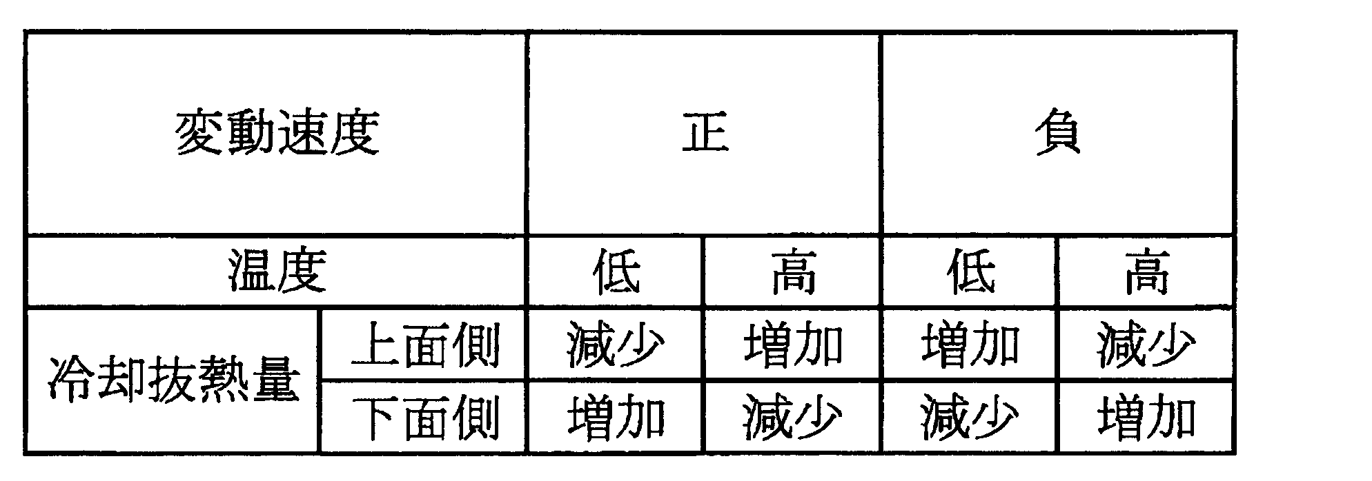
ここで、制御方向決定工程では、上記のように、熱延鋼板Hの定点での変動速度が正の領域で、熱延鋼板Hの定点での平均温度に対して熱延鋼板Hの定点での温度が低い場合は、上面冷却抜熱量が減少する方向及び下面冷却抜熱量が増加する方向の少なくとも一方を制御方向として決定し、上記の平均温度に対して熱延鋼板Hの温度が高い場合は、上面冷却抜熱量が増加する方向及び下面冷却抜熱量が減少する方向の少なくとも一方を制御方向として決定する。
また、この制御方向決定工程では、上記の変動速度が負の領域で、上記の平均温度に対して熱延鋼板Hの温度が低い場合は、上面冷却抜熱量が増加する方向及び下面冷却抜熱量が減少する方向の少なくとも一方を制御方向として決定し、上記の平均温度に対して熱延鋼板Hの温度が高い場合は、上面冷却抜熱量が減少する方向及び下面冷却抜熱量が増加する方向の少なくとも一方を制御方向として決定する。
なお、この冷却方法においても、冷却区間における熱延鋼板Hの上下熱伝達係数比率Xを目標比率Xtと一致させるという制御目標を達成しながら、上面冷却抜熱量と下面冷却抜熱量を調整する必要がある。 Thus, in the target ratio setting process and the cooling control process described above, the temperature measurement process for measuring the temperature (temperature at a fixed point) of the hot rolled steel sheet H on the downstream side of the cooling section in time series, and the hot rolled steel sheet H Fluctuation rate measurement process that measures the variation rate in the vertical direction of the hot-rolled steel sheet H at the same location (fixed point) as the temperature measurement location, and the amount of heat removed from the top surface and the bottom surface based on the temperature measurement result and the variation rate measurement result A control direction determining step for determining a control direction of the cooling heat removal amount, and a cooling heat removal amount for adjusting at least one of the upper surface cooling heat removal amount and the lower surface cooling heat removal amount of the hot-rolled steel sheet H in the cooling section based on the determined control direction. An adjustment step may be newly added.
Here, in the control direction determination step, as described above, the fluctuation speed at the fixed point of the hot-rolled steel sheet H is a positive region, and the fixed temperature of the hot-rolled steel sheet H with respect to the average temperature at the fixed point of the hot-rolled steel sheet H. When the temperature is low, at least one of the direction in which the amount of heat removal from the upper surface cooling decreases and the direction in which the amount of heat removal from the lower surface cooling increases is determined as the control direction, and the temperature of the hot rolled steel sheet H is higher than the above average temperature Determines at least one of the direction in which the upper surface cooling heat removal amount increases and the direction in which the lower surface cooling heat removal amount decreases as the control direction.
In this control direction determination step, when the temperature of the hot-rolled steel sheet H is lower than the average temperature in the region where the fluctuation speed is negative, the upper surface cooling heat removal amount and the lower surface cooling heat removal amount are increased. When the temperature of the hot-rolled steel sheet H is higher than the above average temperature, the direction of decreasing the upper surface cooling heat removal amount and the direction of increasing the lower surface cooling heat removal amount are determined. At least one is determined as a control direction.
Even in this cooling method, it is necessary to adjust the upper surface cooling heat removal amount and the lower surface cooling heat removal amount while achieving the control target of making the upper and lower heat transfer coefficient ratio X of the hot rolled steel sheet H in the cooling section coincide with the target ratio Xt. There is.
また、上側冷却装置14aと下側冷却装置14bの冷却ヘッダー(冷却口31)を間引いて、上側冷却装置14aと下側冷却装置14bから噴射される冷却水の流量や圧力を調整してもよい。例えば冷却ヘッダーを間引く前の上側冷却装置14aの冷却能力が、下側冷却装置14bの冷却能力よりも上回っている場合、上側冷却装置14aを構成する冷却ヘッダーを間引くことが好ましい。 When adjusting the cooling capacity of the
In addition, the cooling headers (cooling ports 31) of the
このため、熱延鋼板Hを均一に冷却することができない。一方、膜沸騰領域では、熱延鋼板Hの表面全体が蒸気膜に覆われた状態で熱延鋼板Hの冷却が行われるので、熱延鋼板Hを均一に冷却することができる。したがって、本実施形態のように熱延鋼板Hの温度が600℃以上の範囲において、熱延鋼板Hをより均一に冷却することができる。 In the above embodiment, the cooling of the hot-rolled steel sheet H by the cooling
For this reason, the hot-rolled steel sheet H cannot be cooled uniformly. On the other hand, in the film boiling region, since the hot-rolled steel sheet H is cooled in a state where the entire surface of the hot-rolled steel sheet H is covered with the vapor film, the hot-rolled steel sheet H can be uniformly cooled. Therefore, the hot-rolled steel sheet H can be cooled more uniformly in the range where the temperature of the hot-rolled steel sheet H is 600 ° C. or more as in this embodiment.
Yz’=Yz×2/z・・・・(1) Therefore, the vertical heat transfer coefficient ratio X of the hot-rolled steel sheet H is fixed in advance, and the steepness is changed stepwise from 3% to 0%, for example, as shown in FIG. Table data indicating a correlation with the temperature standard deviation Y after cooling of the steel plate H is obtained. Then, the temperature standard deviation Y with respect to the steepness z% of the actual hot-rolled steel sheet H is corrected to a temperature standard deviation Y ′ with respect to a predetermined steepness by an interpolation function. Specifically, when the predetermined steepness is set to 2% as the correction condition, the temperature standard deviation Yz ′ is calculated by the following equation (1) based on the temperature standard deviation Yz at the steepness z%. Alternatively, for example, the steepness gradient α in FIG. 12 may be calculated by the least square method or the like, and the temperature standard deviation Yz ′ may be calculated using the gradient α.
Yz ′ = Yz × 2 / z (1)
この表3における上下熱伝達係数比率Xの表示と評価の基準については、表1の評価と同様であるので説明を省略する。この図13又は表3を用いて、急峻度に応じた熱延鋼板Hの温度標準偏差Yを導出できる。そして、例えば、急峻度を2%に補正する場合、表3における評価が“B”となる、すなわち熱延鋼板Hの最小値からの標準偏差の差分が10℃以内となる上下熱伝達係数比率Xを1.1に設定することができる。 Further, in the regression equation of the V-shaped curve shown in FIG. 13, the steepness may be corrected to a predetermined steepness, and the temperature standard deviation Y may be derived from the regression equation. Table 3 shows the temperature standard deviation Y of the hot-rolled steel sheet H when the vertical heat transfer coefficient ratio X is varied as shown in FIG. 13 with respect to the steepness in FIG. The minimum value Ymin from each temperature standard deviation Y (Ymin = 1.2 ° C. when the steepness is 1%, Ymin = 2.3 ° C. when the steepness is 2%, Ymin = 3% when the steepness is 3%) The value obtained by subtracting 3.5 ° C. (difference of standard deviation from the minimum value) and the evaluation of each temperature standard deviation Y are shown.
The display and evaluation criteria for the upper and lower heat transfer coefficient ratio X in Table 3 are the same as those in Table 1 and will not be described. Using FIG. 13 or Table 3, the temperature standard deviation Y of the hot-rolled steel sheet H according to the steepness can be derived. For example, when the steepness is corrected to 2%, the evaluation in Table 3 is “B”, that is, the ratio of the vertical heat transfer coefficient that the difference of the standard deviation from the minimum value of the hot-rolled steel sheet H is within 10 ° C. X can be set to 1.1.

Yz’=Yv×10/v・・・・(2) Similarly, for example, as illustrated in FIG. 14, the sheet feeding speed is changed stepwise from 5 m / sec (300 m / min) to 20 m / sec (1200 m / min), and the sheet feeding speed and the hot rolled steel sheet H are changed. Table data indicating a correlation with the temperature standard deviation Y after cooling is obtained. Then, the temperature standard deviation Y with respect to the sheet passing speed v (m / sec) of the actual hot rolled steel sheet H is corrected to a temperature standard deviation Y ′ with respect to a predetermined sheet passing speed by an interpolation function. Specifically, when the predetermined sheet passing speed is set to 10 (m / sec) as the correction condition, the temperature standard is expressed by the following formula (2) based on the temperature standard deviation Yv at the sheet passing speed v (m / sec). Deviation Yv ′ is calculated. Alternatively, for example, the gradient β of the sheet feeding speed in FIG. 14 may be calculated by a least square method or the like, and the temperature standard deviation Yv ′ may be calculated using the gradient β.
Yz ′ = Yv × 10 / v (2)
この表4における上下熱伝達係数比率Xの表示と評価の基準については、表1の評価と同様であるので説明を省略する。この図15又は表4を用いて、通板速度に応じた熱延鋼板Hの温度標準偏差Yを導出できる。そして、例えば、通板速度を10m/secに補正する場合、表4における評価が“B”となる、すなわち熱延鋼板Hの最小値からの標準偏差の差分が10℃以内となる上下熱伝達係数比率Xを1.1に設定することができる。 Further, in the regression formula of the V-shaped curve shown in FIG. 15, the plate passing speed may be corrected to a predetermined plate passing speed, and the temperature standard deviation Y may be derived from the regression formula. Table 4 shows the temperature standard deviation Y and the temperature standard deviation of the hot-rolled steel sheet H when the vertical heat transfer coefficient ratio X is varied as shown in FIG. 15 with respect to the sheet passing speed in FIG. Minimum value Ymin from Y (Ymin = 1.2 ° C when the plate speed is 5 m / s, Ymin = 2.3 ° C when the plate speed is 10 m / s, and 15 m / s when the plate speed is 15 m / s) Ymin = 3.5 ° C, Ymin = 4.6 ° C when the plate speed is 20m / s (the difference of the standard deviation from the minimum value), and the evaluation of each temperature standard deviation Y Yes.
The display and evaluation criteria for the upper and lower heat transfer coefficient ratio X in Table 4 are the same as those in Table 1 and will not be described. Using FIG. 15 or Table 4, the temperature standard deviation Y of the hot-rolled steel sheet H corresponding to the sheet passing speed can be derived. For example, when correcting the sheet passing speed to 10 m / sec, the evaluation in Table 4 is “B”, that is, the vertical heat transfer is such that the difference of the standard deviation from the minimum value of the hot rolled steel sheet H is within 10 ° C. The coefficient ratio X can be set to 1.1.

また、温度標準偏差Yの大きさに基づいて、その温度標準偏差Yが許容範囲、例えば最小値Yminから最小値Ymin+10℃以内の範囲に収まるように上下熱伝達係数比率Xを決定することができる。この上下熱伝達係数比率Xを決定する方法は、図6及び図7を用いて説明した上記実施形態と同様であるので、詳細な説明を省略する。なお、この温度標準偏差Yを最小値Yminから最小値Ymin+10℃以内の範囲に収めることにより、降伏応力、引張強さなどのバラつきを製造許容範囲内に抑えられ、熱延鋼板Hを均一に冷却できる。
また、かなりのばらつきはあるものの、冷却水量密度比率が、温度標準偏差Yが最小値Yminとなる冷却水量密度比率に対して±5%以内であれば、温度標準偏差Yを最小値Yminから最小値Ymin+10℃以内の範囲に収めることができる。すなわち、冷却水量密度を用いる場合、冷却水量密度の上下比率(冷却水量密度比率)を、温度標準偏差Yが最小値Yminとなる冷却水量密度比率に対して±5%以内に設定することが望ましい。ただし、この許容範囲は必ずしも上下同水量密度を含むとは限らない。 That is, if the fluctuation position of the temperature associated with the wave shape of these hot-rolled steel sheets H is grasped, it becomes clear whether the temperature standard deviation Y currently generated is generated by the upper cooling or the lower cooling. It becomes possible to do. Therefore, the increase / decrease direction (control direction) of the upper cooling capacity (upper surface cooling heat removal amount) and the lower cooling capacity (lower surface cooling heat removal amount) to reduce the temperature standard deviation Y is determined, and the vertical heat transfer coefficient ratio X is adjusted. can do.
Further, based on the magnitude of the temperature standard deviation Y, the vertical heat transfer coefficient ratio X can be determined so that the temperature standard deviation Y falls within an allowable range, for example, the range from the minimum value Ymin to the minimum value Ymin + 10 ° C. . The method for determining the upper and lower heat transfer coefficient ratio X is the same as that in the embodiment described with reference to FIGS. By keeping the temperature standard deviation Y within the range from the minimum value Ymin to the minimum value Ymin + 10 ° C, variations in yield stress, tensile strength, etc. can be kept within the manufacturing tolerances, and the hot-rolled steel sheet H can be cooled uniformly. it can.
In addition, although there is considerable variation, if the cooling water amount density ratio is within ± 5% of the cooling water amount density ratio at which the temperature standard deviation Y is the minimum value Ymin, the temperature standard deviation Y is minimized from the minimum value Ymin. The value can be kept within a range of Ymin + 10 ° C. That is, when the cooling water amount density is used, it is desirable that the ratio of the cooling water amount density (cooling water amount density ratio) is set within ± 5% with respect to the cooling water amount density ratio at which the temperature standard deviation Y is the minimum value Ymin. . However, this allowable range does not necessarily include the same upper and lower water density.
また、分割冷却区間Z2においては、その下流側における温度計40と形状計41の測定結果に基づいて、上側冷却装置14aと下側冷却装置14bの冷却能力がフィードフォワード制御されてもよいし、或いはフィードバック制御されてもよい。いずれの場合においても、分割冷却区間Z2において、上面冷却抜熱量及び下面冷却抜熱量の少なくとも一方が調整される。 For example, in the divided cooling zone Z1, the cooling capacity of the
In the divided cooling zone Z2, the cooling capacity of the
本願発明者は、実施例1として、板厚2.3mm、板幅1200mmのハイテン(いわゆる高張力鋼板)を材料とし、当該材料に中波形状、耳波形状をそれぞれ形成させ、その急峻度を0%(波形成無し)~2%までの種々の値に変更して冷却を行った場合の、後工程(即ち、冷延工程)における冷延ゲージ変動(板厚変動)と板幅方向平均温度変動を測定し、評価を行った。なお、本実施例1および以下に説明する実施例2、3では、便宜上、中波形状を形成した場合の急峻度を-0.5%~-2%と表し、耳波形状を形成した場合の急峻度を0.5%~2%と表した。
また、中波形状及び耳波形状の測定は市販の形状測定器を用いて測定したものであり、中波形状の測定箇所は板中央から左右30mm以内の板中央部であり、耳波形状の測定箇所は板端から25mmの箇所とした。更に、本実施例1においては、冷却時の上下冷却比(上下熱伝達係数比率)は上冷却:下冷却=1.2:1とし、通板速度を400m/min、鋼板の巻き取り温度(CT)を500℃とした。
その測定結果及び評価結果を以下の表5に示す。このとき、以下の実施例における評価基準としては、後工程における冷延ゲージ変動が0~25μmに抑えられたものをA(製品として良好)、25~50μmであったものをB(許容範囲)、50μm超であったものをC(製品不良)として評価している。なお、表5中の総合評価については、後述する。また、表5中には、参考のため鋼板圧延方向における各波形状の温度標準偏差も記載した。 (Example 1)
The inventor of the present application uses, as a material, high tension (so-called high-tensile steel plate) with a plate thickness of 2.3 mm and a plate width of 1200 mm as a material, and forms a medium wave shape and an ear wave shape in the material, respectively, and the steepness is determined. Cold rolling gauge fluctuation (sheet thickness fluctuation) and average in the sheet width direction in the subsequent process (ie, cold rolling process) when cooling is performed with various values ranging from 0% (no wave formation) to 2%. Temperature fluctuation was measured and evaluated. In Example 1 and Examples 2 and 3 described below, for the sake of convenience, the steepness when the medium wave shape is formed is represented as -0.5% to -2%, and the case where the ear wave shape is formed. The steepness was expressed as 0.5% to 2%.
Further, the measurement of the medium wave shape and the ear wave shape was measured using a commercially available shape measuring instrument, and the measurement location of the medium wave shape is the center portion of the plate within 30 mm on the left and right sides of the plate center. The measurement location was 25 mm from the edge of the plate. Furthermore, in Example 1, the vertical cooling ratio (vertical heat transfer coefficient ratio) at the time of cooling was set to upper cooling: lower cooling = 1.2: 1, the plate speed was 400 m / min, and the steel sheet winding temperature ( CT) was 500 ° C.
The measurement results and evaluation results are shown in Table 5 below. At this time, the evaluation criteria in the following examples are A (good as a product) in which the cold-rolling gauge fluctuation in the subsequent process is suppressed to 0 to 25 μm, and B (allowable range) in which 25 to 50 μm. In this case, the value exceeding 50 μm is evaluated as C (product defect). The comprehensive evaluation in Table 5 will be described later. In Table 5, the temperature standard deviation of each wave shape in the steel sheet rolling direction is also shown for reference.

次に、本願発明者は、実施例2として、上記実施例1と同様の材料に中波形状、耳波形状をそれぞれ形成させ、その急峻度を0%(波形成無し)~2%までの種々の値に変更して冷却を行った場合の、後工程(即ち、冷延工程)における冷延ゲージ変動(板厚変動)と板幅方向平均温度変動を測定し、評価を行った。なお、本実施例2では、通板速度を600m/minとし、その他の条件は実施例1と同一とした。その測定結果及び評価結果を以下の表6に示す。 (Example 2)
Next, the inventor of the present application forms a medium wave shape and an ear wave shape in the same material as in Example 1 as Example 2, and the steepness is 0% (no wave formation) to 2%. When cooling was performed by changing to various values, the cold-rolling gauge fluctuation (sheet thickness fluctuation) and the sheet width direction average temperature fluctuation in the subsequent process (that is, cold rolling process) were measured and evaluated. In Example 2, the sheet passing speed was 600 m / min, and the other conditions were the same as in Example 1. The measurement results and evaluation results are shown in Table 6 below.

次に、本願発明者は、実施例3として、上記実施例1、2と同様の材料に中波形状、耳波形状をそれぞれ形成させ、その急峻度を0%(波形成無し)~2%までの種々の値に変更して冷却を行った場合の、後工程(即ち、冷延工程)における冷延ゲージ変動(板厚変動)と板幅方向平均温度変動を測定し、評価を行った。なお、本実施例3では、冷却時の上下冷却比(上下熱伝達係数比率)を上冷却:下冷却=1.1:1とし、その他の条件は上記実施例1と同一とした。その測定結果及び評価結果を以下の表7に示す。 (Example 3)
Next, the inventor of the present application forms a medium wave shape and an ear wave shape in the same material as in Examples 1 and 2 as Example 3, and the steepness is 0% (no wave formation) to 2%. In the case of cooling by changing to various values up to the above, the cold-rolled gauge fluctuation (sheet thickness fluctuation) and the sheet width direction average temperature fluctuation in the subsequent process (that is, cold rolling process) were measured and evaluated. . In Example 3, the vertical cooling ratio (upper and lower heat transfer coefficient ratio) during cooling was set to upper cooling: lower cooling = 1.1: 1, and the other conditions were the same as those in Example 1. The measurement results and evaluation results are shown in Table 7 below.

11 加熱炉
12 粗圧延機
12a ワークロール
12b 4重圧延機
13 仕上圧延機
13a 仕上げ圧延ロール
14 冷却装置
14a 上側冷却装置
14b 下側冷却装置
15 巻取装置
16 幅方向圧延機
31 冷却口
32 搬送ロール
40 温度計
41 形状計
H 熱延鋼板
S スラブ
Z1、Z2 分割冷却区間 DESCRIPTION OF
Claims (19)
- 鋼材を仕上圧延機で熱間圧延することにより、圧延方向に周期的に波高さが変動する耳波形状が形成された熱延鋼板を得る熱間圧延工程と;
前記熱延鋼板を、その通板経路上に設けられた冷却区間において冷却する冷却工程と;
を備え、
前記熱間圧延工程は、
予め実験的に求めておいた、前記熱延鋼板の前記耳波形状の急峻度と前記熱延鋼板の冷却中または冷却後の温度標準偏差Yと相関関係を示す第1の相関データに基づいて、前記耳波形状の目標急峻度を設定する目標急峻度設定工程と、
前記耳波形状の急峻度が前記目標急峻度と一致するように、前記仕上圧延機の運転パラメータを制御する形状制御工程と、
を含むことを特徴とする鋼板製造方法。 A hot rolling step of obtaining a hot-rolled steel sheet in which an ear wave shape in which the wave height fluctuates periodically in the rolling direction is formed by hot rolling the steel material with a finish rolling mill;
A cooling step of cooling the hot-rolled steel sheet in a cooling section provided on the plate passage;
With
The hot rolling step is
Based on first correlation data indicating a correlation between the steepness of the ear wave shape of the hot-rolled steel sheet and the temperature standard deviation Y during or after cooling of the hot-rolled steel sheet, which has been experimentally obtained in advance. A target steepness setting step for setting a target steepness of the ear wave shape;
A shape control step for controlling operating parameters of the finishing mill such that the steepness of the ear wave shape matches the target steepness;
A method for producing a steel sheet, comprising: - 前記目標急峻度設定工程では、前記目標急峻度を0%超1%以内に設定することを特徴とする鋼板製造方法。 In the target steepness setting step, the target steepness is set to more than 0% and within 1%.
- 前記冷却工程が、
予め実験的に前記熱延鋼板の急峻度及び通板速度を一定値とする条件下で求めておいた、前記熱延鋼板の上下面の熱伝達係数の比率である上下熱伝達係数比率Xと前記熱延鋼板の冷却中または冷却後の前記温度標準偏差Yとの相関関係を示す第2の相関データに基づいて、前記温度標準偏差Yが最小値Yminとなる上下熱伝達係数比率X1を目標比率Xtとして設定する目標比率設定工程と;
前記冷却区間における前記熱延鋼板の上下熱伝達係数比率Xが前記目標比率Xtと一致するように、前記冷却区間における前記熱延鋼板の上面冷却抜熱量と下面冷却抜熱量との少なくとも一方を制御する冷却制御工程と;
を有することを特徴とする請求項1又は2に記載の鋼板製造方法。 The cooling step is
The upper and lower heat transfer coefficient ratio X, which is the ratio of the heat transfer coefficients of the upper and lower surfaces of the hot rolled steel sheet, experimentally determined in advance under the condition that the steepness and the sheet passing speed of the hot rolled steel sheet are constant values, Based on the second correlation data indicating the correlation with the temperature standard deviation Y during or after cooling of the hot-rolled steel sheet, the target is the vertical heat transfer coefficient ratio X1 at which the temperature standard deviation Y becomes the minimum value Ymin. A target ratio setting step to set as the ratio Xt;
Control at least one of the upper surface cooling heat removal amount and the lower surface cooling heat removal amount of the hot rolled steel sheet in the cooling section so that the vertical heat transfer coefficient ratio X of the hot rolled steel sheet in the cooling section matches the target ratio Xt. A cooling control step to perform;
The steel sheet manufacturing method according to claim 1 or 2, wherein - 前記目標比率設定工程では、前記第2の相関データに基づいて、前記温度標準偏差Yが最小値Yminから最小値Ymin+10℃以内の範囲に収まる上下熱伝達係数比率Xを前記目標比率Xtとして設定することを特徴とする請求項3に記載の鋼板製造方法。 In the target ratio setting step, based on the second correlation data, a vertical heat transfer coefficient ratio X in which the temperature standard deviation Y falls within the range of the minimum value Ymin to the minimum value Ymin + 10 ° C. is set as the target ratio Xt. The method for producing a steel sheet according to claim 3.
- 前記第2の相関データは、前記急峻度及び前記通板速度の値が異なる複数の条件のそれぞれについて用意されており、
前記目標比率設定工程では、前記複数の第2の相関データの内、前記急峻度及び前記通板速度の実測値に応じた第2の相関データに基づいて前記目標比率Xtを設定することを特徴とする請求項3に記載の鋼板製造方法。 The second correlation data is prepared for each of a plurality of conditions with different values of the steepness and the plate passing speed,
In the target ratio setting step, the target ratio Xt is set based on second correlation data corresponding to the measured values of the steepness and the sheet passing speed among the plurality of second correlation data. The steel plate manufacturing method according to claim 3. - 前記第2の相関データは、前記上下熱伝達係数比率Xと前記温度標準偏差Yとの相関関係を回帰式で示すデータであることを特徴とする請求項3に記載の鋼板製造方法。 The steel sheet manufacturing method according to claim 3, wherein the second correlation data is data indicating a correlation between the upper and lower heat transfer coefficient ratio X and the temperature standard deviation Y by a regression equation.
- 前記回帰式は線形回帰によって導出されたものであることを特徴とする請求項6に記載の鋼板製造方法。 The steel sheet manufacturing method according to claim 6, wherein the regression equation is derived by linear regression.
- 前記第2の相関データは、前記上下熱伝達係数比率Xと前記温度標準偏差Yとの相関関係をテーブルで示すデータであることを特徴とする請求項3に記載の鋼板製造方法。 The steel sheet manufacturing method according to claim 3, wherein the second correlation data is data indicating a correlation between the upper and lower heat transfer coefficient ratio X and the temperature standard deviation Y in a table.
- 前記冷却区間の下流側における前記熱延鋼板の温度を時系列で測定する温度測定工程と;
前記温度の測定結果に基づいて前記温度の時系列平均値を算出する温度平均値算出工程と;
前記温度の時系列平均値が所定の目標温度と一致するように、前記冷却区間における前記熱延鋼板の前記上面冷却抜熱量と前記下面冷却抜熱量との合計値を調整する冷却抜熱量調整工程と;
をさらに有することを特徴とする請求項3に記載の鋼板製造方法。 A temperature measuring step of measuring the temperature of the hot-rolled steel sheet downstream of the cooling section in time series;
A temperature average value calculating step of calculating a time-series average value of the temperature based on the measurement result of the temperature;
A cooling heat removal amount adjustment step of adjusting a total value of the upper surface cooling heat removal amount and the lower surface cooling heat removal amount of the hot-rolled steel sheet in the cooling section so that the time-series average value of the temperatures coincides with a predetermined target temperature. When;
The steel sheet manufacturing method according to claim 3, further comprising: - 前記冷却区間の下流側における前記熱延鋼板の温度を時系列で測定する温度測定工程と;
前記冷却区間の下流側における前記熱延鋼板の温度測定箇所と同一箇所での前記熱延鋼板の鉛直方向の変動速度を時系列で測定する変動速度測定工程と;
前記熱延鋼板の鉛直方向の上向きを正とした場合において、前記変動速度が正の領域で、前記熱延鋼板の波形状1周期以上の範囲の平均温度に対して前記熱延鋼板の温度が低い場合は、前記上面冷却抜熱量が減少する方向及び前記下面冷却抜熱量が増加する方向の少なくとも一方を制御方向として決定し、前記平均温度に対して前記熱延鋼板の温度が高い場合は、前記上面冷却抜熱量が増加する方向及び前記下面冷却抜熱量が減少する方向の少なくとも一方を前記制御方向として決定し、
前記変動速度が負の領域で、前記平均温度に対して前記熱延鋼板の温度が低い場合は、前記上面冷却抜熱量が増加する方向及び前記下面冷却抜熱量が減少する方向の少なくとも一方を前記制御方向として決定し、前記平均温度に対して前記熱延鋼板の温度が高い場合は、前記上面冷却抜熱量が減少する方向及び前記下面冷却抜熱量が増加する方向の少なくとも一方を前記制御方向として決定する制御方向決定工程と;
前記制御方向決定工程にて決定された前記制御方向に基づいて、前記冷却区間における前記熱延鋼板の前記上面冷却抜熱量及び前記下面冷却抜熱量の少なくとも一方を調整する冷却抜熱量調整工程と;
をさらに有することを特徴とする請求項3に記載の鋼板製造方法。 A temperature measuring step of measuring the temperature of the hot-rolled steel sheet downstream of the cooling section in time series;
A fluctuation rate measurement step of measuring, in a time series, a fluctuation rate in the vertical direction of the hot-rolled steel plate at the same location as the temperature measurement location of the hot-rolled steel plate on the downstream side of the cooling section;
When the upward direction in the vertical direction of the hot-rolled steel sheet is positive, the temperature of the hot-rolled steel sheet is in an area where the fluctuation rate is positive, with respect to the average temperature in the range of one or more wave shapes of the hot-rolled steel sheet. If it is low, determine at least one of the direction in which the upper surface cooling heat removal amount decreases and the direction in which the lower surface cooling heat removal amount increases as the control direction, and when the temperature of the hot-rolled steel sheet is higher than the average temperature, Determining at least one of the direction in which the upper surface cooling heat removal amount increases and the direction in which the lower surface cooling heat removal amount decreases as the control direction;
When the temperature of the hot-rolled steel sheet is lower than the average temperature in a region where the fluctuation speed is negative, at least one of the direction in which the upper surface cooling heat removal amount increases and the direction in which the lower surface cooling heat removal amount decreases is When the temperature of the hot-rolled steel sheet is determined as a control direction and the average temperature is higher, at least one of the direction in which the upper surface cooling heat removal amount decreases and the direction in which the lower surface cooling heat removal amount increases is set as the control direction. A control direction determining step to determine;
A cooling heat removal amount adjustment step of adjusting at least one of the upper surface cooling heat removal amount and the lower surface cooling heat removal amount of the hot-rolled steel sheet in the cooling section based on the control direction determined in the control direction determination step;
The steel sheet manufacturing method according to claim 3, further comprising: - 前記冷却区間は、前記熱延鋼板の通板方向に沿って複数の分割冷却区間に分割されており、
前記温度測定工程及び前記変動速度測定工程では、前記分割冷却区間の境のそれぞれにおいて前記熱延鋼板の温度及び変動速度を時系列的に測定し、
前記制御方向決定工程では、前記分割冷却区間の境のそれぞれにおける前記熱延鋼板の温度及び変動速度の測定結果に基づいて、前記分割冷却区間のそれぞれについて前記熱延鋼板の上下面の冷却抜熱量の増減方向を決定し、
前記冷却抜熱量調整工程では、前記分割冷却区間のそれぞれについて決定された前記制御方向に基づいて、前記分割冷却区間のそれぞれにおいて前記熱延鋼板の前記上面冷却抜熱量及び前記下面冷却抜熱量の少なくとも一方を調整するためにフィードバック制御又はフィードフォワード制御を行う
ことを特徴とする請求項10に記載の鋼板製造方法。 The cooling section is divided into a plurality of divided cooling sections along the sheet passing direction of the hot-rolled steel sheet,
In the temperature measurement step and the fluctuation rate measurement step, the temperature and fluctuation rate of the hot-rolled steel sheet are measured in time series at each boundary of the divided cooling section,
In the control direction determination step, based on the measurement results of the temperature and the fluctuation rate of the hot-rolled steel sheet at each boundary of the divided cooling section, the amount of cooling heat removed from the upper and lower surfaces of the hot-rolled steel sheet for each of the divided cooling sections. Determine the direction of increase or decrease
In the cooling heat removal amount adjustment step, based on the control direction determined for each of the divided cooling sections, at least the upper surface cooling heat removal amount and the lower surface cooling heat removal amount of the hot-rolled steel sheet in each of the divided cooling sections. The steel sheet manufacturing method according to claim 10, wherein feedback control or feedforward control is performed to adjust one of them. - 前記分割冷却区間の境のそれぞれにおいて前記熱延鋼板の前記急峻度又は前記通板速度を測定する測定工程と;
前記急峻度または前記通板速度の測定結果に基づいて、前記分割冷却区間のそれぞれにおける前記熱延鋼板の前記上面冷却抜熱量及び前記下面冷却抜熱量の少なくとも一方を補正する冷却抜熱量補正工程と;
をさらに有することを特徴とする請求項11に記載の鋼板製造方法。 A measuring step of measuring the steepness of the hot-rolled steel sheet or the sheet passing speed at each boundary of the divided cooling section;
A cooling heat removal amount correcting step for correcting at least one of the upper surface cooling heat removal amount and the lower surface cooling heat removal amount of the hot-rolled steel sheet in each of the divided cooling sections based on the measurement result of the steepness or the sheet passing speed; ;
The steel sheet manufacturing method according to claim 11, further comprising: - 前記冷却区間の下流側において、前記熱延鋼板の温度標準偏差が許容される範囲に入るように、前記熱延鋼板をさらに冷却する後冷却工程をさらに有することを特徴とする請求項3に記載の鋼板製造方法。
4. The method according to claim 3, further comprising a post-cooling step of further cooling the hot-rolled steel sheet so that a temperature standard deviation of the hot-rolled steel sheet falls within an allowable range on the downstream side of the cooling section. Steel plate manufacturing method.
- 前記冷却区間における前記熱延鋼板の通板速度は、550m/min以上から機械的な限界速度以下の範囲で設定されていることを特徴とする請求項3に記載の鋼板製造方法。 The steel sheet manufacturing method according to claim 3, wherein a sheet passing speed of the hot-rolled steel sheet in the cooling section is set in a range of 550 m / min or more to a mechanical limit speed or less.
- 前記熱延鋼板の引張強度は800MPa以上であることを特徴とする請求項14に記載の鋼板製造方法。 The steel sheet manufacturing method according to claim 14, wherein the hot-rolled steel sheet has a tensile strength of 800 MPa or more.
- 前記仕上圧延機は複数の圧延スタンドから構成されており、
前記複数の圧延スタンド同士の間で前記熱延鋼板の補助冷却を行う補助冷却工程をさらに有することを特徴とする請求項14に記載の鋼板製造方法。 The finish rolling mill is composed of a plurality of rolling stands,
The steel sheet manufacturing method according to claim 14, further comprising an auxiliary cooling step of performing auxiliary cooling of the hot-rolled steel sheet between the plurality of rolling stands. - 前記冷却区間には、前記熱延鋼板の上面に冷却水を噴射する複数のヘッダーを有する上側冷却装置と、前記熱延鋼板の下面に冷却水を噴射する複数のヘッダーを有する下側冷却装置とが設けられており、
前記上面冷却抜熱量及び前記下面冷却抜熱量は、前記各ヘッダーをオンオフ制御することによって調整されることを特徴とする請求項3に記載の鋼板製造方法。 In the cooling section, an upper cooling device having a plurality of headers for injecting cooling water onto the upper surface of the hot-rolled steel plate, and a lower cooling device having a plurality of headers for injecting cooling water to the lower surface of the hot-rolled steel plate, Is provided,
The steel sheet manufacturing method according to claim 3, wherein the upper surface cooling heat removal amount and the lower surface cooling heat removal amount are adjusted by on / off controlling the headers. - 前記冷却区間には、前記熱延鋼板の上面に冷却水を噴射する複数のヘッダーを有する上側冷却装置と、前記熱延鋼板の下面に冷却水を噴射する複数のヘッダーを有する下側冷却装置とが設けられており、
前記上面冷却抜熱量及び前記下面冷却抜熱量は、前記各ヘッダーの水量密度、圧力及び水温の少なくとも一つを制御することによって調整されることを特徴とする請求項3に記載の鋼板製造方法。 In the cooling section, an upper cooling device having a plurality of headers for injecting cooling water onto the upper surface of the hot-rolled steel plate, and a lower cooling device having a plurality of headers for injecting cooling water to the lower surface of the hot-rolled steel plate, Is provided,
The steel sheet manufacturing method according to claim 3, wherein the upper surface cooling heat removal amount and the lower surface cooling heat removal amount are adjusted by controlling at least one of a water amount density, a pressure, and a water temperature of each header. - 前記冷却区間での冷却は、前記熱延鋼板の温度が600℃以上の範囲で行われることを特徴とする請求項3に記載の鋼板製造方法。 The method for manufacturing a steel sheet according to claim 3, wherein the cooling in the cooling section is performed in a range where the temperature of the hot-rolled steel sheet is 600 ° C or higher.
Priority Applications (7)
| Application Number | Priority Date | Filing Date | Title |
|---|---|---|---|
| JP2013511451A JP5310964B1 (en) | 2012-12-06 | 2012-12-06 | Steel plate manufacturing method |
| KR1020137019174A KR101528690B1 (en) | 2012-12-06 | 2012-12-06 | Method for manufacturing steel sheet |
| PCT/JP2012/081634 WO2014087516A1 (en) | 2012-12-06 | 2012-12-06 | Method for producing steel sheet |
| CN201280005604.4A CN103998154B (en) | 2012-12-06 | 2012-12-06 | Steel sheet manufacturing method |
| EP12873879.6A EP2933031B1 (en) | 2012-12-06 | 2012-12-06 | Method for producing steel sheet |
| US14/111,959 US9211574B2 (en) | 2011-07-27 | 2012-12-06 | Method for manufacturing steel sheet |
| BR112013028631-8A BR112013028631B1 (en) | 2012-12-06 | 2012-12-06 | METHOD FOR STEEL SHEET PRODUCTION |
Applications Claiming Priority (1)
| Application Number | Priority Date | Filing Date | Title |
|---|---|---|---|
| PCT/JP2012/081634 WO2014087516A1 (en) | 2012-12-06 | 2012-12-06 | Method for producing steel sheet |
Publications (1)
| Publication Number | Publication Date |
|---|---|
| WO2014087516A1 true WO2014087516A1 (en) | 2014-06-12 |
Family
ID=49529542
Family Applications (1)
| Application Number | Title | Priority Date | Filing Date |
|---|---|---|---|
| PCT/JP2012/081634 WO2014087516A1 (en) | 2011-07-27 | 2012-12-06 | Method for producing steel sheet |
Country Status (6)
| Country | Link |
|---|---|
| EP (1) | EP2933031B1 (en) |
| JP (1) | JP5310964B1 (en) |
| KR (1) | KR101528690B1 (en) |
| CN (1) | CN103998154B (en) |
| BR (1) | BR112013028631B1 (en) |
| WO (1) | WO2014087516A1 (en) |
Families Citing this family (2)
| Publication number | Priority date | Publication date | Assignee | Title |
|---|---|---|---|---|
| KR20180033500A (en) * | 2015-06-08 | 2018-04-03 | 닛신 세이코 가부시키가이샤 | Pretreatment method for painting or printing |
| CN113182362B (en) * | 2021-04-01 | 2022-07-08 | 本钢板材股份有限公司 | Production method of high-flatness cold-rolled strip steel |
Citations (6)
| Publication number | Priority date | Publication date | Assignee | Title |
|---|---|---|---|---|
| JPH06328117A (en) * | 1993-05-18 | 1994-11-29 | Nippon Steel Corp | Method for injecting water in rot cooling of continuous hot rolling |
| JPH0763750B2 (en) * | 1988-12-28 | 1995-07-12 | 新日本製鐵株式会社 | Cooling control device for hot rolled steel sheet |
| JP2003048003A (en) | 2001-07-31 | 2003-02-18 | Nkk Corp | Method for manufacturing hot-rolled steel sheet |
| JP2005074463A (en) | 2003-08-29 | 2005-03-24 | Nippon Steel Corp | Cooling method of steel plate |
| JP2005271052A (en) | 2004-03-25 | 2005-10-06 | Jfe Steel Kk | Hot-rolling method |
| JP2011073054A (en) * | 2009-10-02 | 2011-04-14 | Nippon Steel Corp | Method and apparatus for cooling hot-rolled steel sheet |
Family Cites Families (9)
| Publication number | Priority date | Publication date | Assignee | Title |
|---|---|---|---|---|
| JPH11347629A (en) * | 1998-06-09 | 1999-12-21 | Nkk Corp | Straightening and cooling device for high temperature steel plate and its straightening and cooling method |
| US6615633B1 (en) * | 1999-11-18 | 2003-09-09 | Nippon Steel Corporation | Metal plateness controlling method and device |
| JP4392115B2 (en) * | 2000-08-03 | 2009-12-24 | 日鐵プラント設計株式会社 | Method and apparatus for controlling flatness of metal plate |
| JP4209746B2 (en) * | 2003-08-21 | 2009-01-14 | 株式会社日立製作所 | Rolling mill and rolling method |
| JP2007216246A (en) * | 2006-02-15 | 2007-08-30 | Jfe Steel Kk | Method for controlling shape of metal strip in hot rolling |
| JP4957586B2 (en) * | 2008-02-29 | 2012-06-20 | 住友金属工業株式会社 | Manufacturing method of hot-rolled steel sheet and manufacturing equipment arrangement |
| JP5124856B2 (en) * | 2008-10-31 | 2013-01-23 | 新日鐵住金株式会社 | Hot rolled steel sheet manufacturing apparatus and hot rolled steel sheet manufacturing method |
| CN101780478B (en) * | 2009-01-21 | 2012-07-04 | 中冶赛迪工程技术股份有限公司 | Method and device for controlling strip shape and precision of hot rolling steel strips and plates |
| EP2505278B1 (en) * | 2009-11-24 | 2015-09-23 | Nippon Steel & Sumitomo Metal Corporation | Hot-rolled steel sheet manufacturing method, and hot-rolled steel sheet manufacturing device |
-
2012
- 2012-12-06 EP EP12873879.6A patent/EP2933031B1/en active Active
- 2012-12-06 WO PCT/JP2012/081634 patent/WO2014087516A1/en active Application Filing
- 2012-12-06 JP JP2013511451A patent/JP5310964B1/en active Active
- 2012-12-06 BR BR112013028631-8A patent/BR112013028631B1/en active IP Right Grant
- 2012-12-06 CN CN201280005604.4A patent/CN103998154B/en active Active
- 2012-12-06 KR KR1020137019174A patent/KR101528690B1/en active IP Right Grant
Patent Citations (6)
| Publication number | Priority date | Publication date | Assignee | Title |
|---|---|---|---|---|
| JPH0763750B2 (en) * | 1988-12-28 | 1995-07-12 | 新日本製鐵株式会社 | Cooling control device for hot rolled steel sheet |
| JPH06328117A (en) * | 1993-05-18 | 1994-11-29 | Nippon Steel Corp | Method for injecting water in rot cooling of continuous hot rolling |
| JP2003048003A (en) | 2001-07-31 | 2003-02-18 | Nkk Corp | Method for manufacturing hot-rolled steel sheet |
| JP2005074463A (en) | 2003-08-29 | 2005-03-24 | Nippon Steel Corp | Cooling method of steel plate |
| JP2005271052A (en) | 2004-03-25 | 2005-10-06 | Jfe Steel Kk | Hot-rolling method |
| JP2011073054A (en) * | 2009-10-02 | 2011-04-14 | Nippon Steel Corp | Method and apparatus for cooling hot-rolled steel sheet |
Also Published As
| Publication number | Publication date |
|---|---|
| CN103998154B (en) | 2015-09-09 |
| JP5310964B1 (en) | 2013-10-09 |
| KR20140100883A (en) | 2014-08-18 |
| EP2933031A1 (en) | 2015-10-21 |
| KR101528690B1 (en) | 2015-06-12 |
| BR112013028631A2 (en) | 2017-01-24 |
| CN103998154A (en) | 2014-08-20 |
| EP2933031A4 (en) | 2016-08-24 |
| BR112013028631B1 (en) | 2022-02-15 |
| EP2933031B1 (en) | 2018-11-14 |
| JPWO2014087516A1 (en) | 2017-01-05 |
Similar Documents
| Publication | Publication Date | Title |
|---|---|---|
| CN104511484B (en) | The micro-middle wave board-shape control method of a kind of hot-strip | |
| EP3426418A1 (en) | Method and apparatus for controlling metal strip profile during rolling with direct measurement of process parameters | |
| US9186710B2 (en) | Method for cooling hot-rolled steel sheet | |
| US9566625B2 (en) | Apparatus for cooling hot-rolled steel sheet | |
| JP5310965B1 (en) | Hot-rolled steel sheet cooling method | |
| EP2929949B1 (en) | Device for cooling hot-rolled steel sheet | |
| JP5310964B1 (en) | Steel plate manufacturing method | |
| JP5626275B2 (en) | Method for cooling hot-rolled steel sheet | |
| JP2008238241A (en) | Manufacturing method of aluminum metal sheet | |
| US9211574B2 (en) | Method for manufacturing steel sheet | |
| JP3596460B2 (en) | Heat treatment method for thick steel plate and heat treatment equipment | |
| TWI516317B (en) | Steel sheet manufacturing method | |
| JP5278580B2 (en) | Hot-rolled steel plate cooling device and cooling method | |
| TWI477328B (en) | Apparatus for cooling hot rolled steel sheet | |
| JP5644811B2 (en) | Method for cooling hot-rolled steel sheet | |
| TWI515054B (en) | Method of cooling hot rolled steel sheet | |
| JP5673370B2 (en) | Method for cooling hot-rolled steel sheet | |
| JP4964061B2 (en) | Control method for steel wire rod cooling | |
| JP6551282B2 (en) | Hot finish rolling method | |
| JP2003275804A (en) | Method for manufacturing hot rolled steel strip |
Legal Events
| Date | Code | Title | Description |
|---|---|---|---|
| ENP | Entry into the national phase |
Ref document number: 2013511451 Country of ref document: JP Kind code of ref document: A |
|
| ENP | Entry into the national phase |
Ref document number: 20137019174 Country of ref document: KR Kind code of ref document: A |
|
| WWE | Wipo information: entry into national phase |
Ref document number: 2012873879 Country of ref document: EP |
|
| WWE | Wipo information: entry into national phase |
Ref document number: 14111959 Country of ref document: US |
|
| REG | Reference to national code |
Ref country code: BR Ref legal event code: B01A Ref document number: 112013028631 Country of ref document: BR |
|
| 121 | Ep: the epo has been informed by wipo that ep was designated in this application |
Ref document number: 12873879 Country of ref document: EP Kind code of ref document: A1 |
|
| NENP | Non-entry into the national phase |
Ref country code: DE |
|
| ENP | Entry into the national phase |
Ref document number: 112013028631 Country of ref document: BR Kind code of ref document: A2 Effective date: 20131106 |