WO2014084013A1 - 廃熱発電装置 - Google Patents
廃熱発電装置 Download PDFInfo
- Publication number
- WO2014084013A1 WO2014084013A1 PCT/JP2013/079988 JP2013079988W WO2014084013A1 WO 2014084013 A1 WO2014084013 A1 WO 2014084013A1 JP 2013079988 W JP2013079988 W JP 2013079988W WO 2014084013 A1 WO2014084013 A1 WO 2014084013A1
- Authority
- WO
- WIPO (PCT)
- Prior art keywords
- power generation
- waste heat
- working medium
- pump
- evaporator
- Prior art date
- Legal status (The legal status is an assumption and is not a legal conclusion. Google has not performed a legal analysis and makes no representation as to the accuracy of the status listed.)
- Ceased
Links
Images
Classifications
-
- F—MECHANICAL ENGINEERING; LIGHTING; HEATING; WEAPONS; BLASTING
- F01—MACHINES OR ENGINES IN GENERAL; ENGINE PLANTS IN GENERAL; STEAM ENGINES
- F01K—STEAM ENGINE PLANTS; STEAM ACCUMULATORS; ENGINE PLANTS NOT OTHERWISE PROVIDED FOR; ENGINES USING SPECIAL WORKING FLUIDS OR CYCLES
- F01K13/00—General layout or general methods of operation of complete plants
- F01K13/02—Controlling, e.g. stopping or starting
-
- F—MECHANICAL ENGINEERING; LIGHTING; HEATING; WEAPONS; BLASTING
- F01—MACHINES OR ENGINES IN GENERAL; ENGINE PLANTS IN GENERAL; STEAM ENGINES
- F01K—STEAM ENGINE PLANTS; STEAM ACCUMULATORS; ENGINE PLANTS NOT OTHERWISE PROVIDED FOR; ENGINES USING SPECIAL WORKING FLUIDS OR CYCLES
- F01K13/00—General layout or general methods of operation of complete plants
- F01K13/003—Arrangements for measuring or testing
-
- F—MECHANICAL ENGINEERING; LIGHTING; HEATING; WEAPONS; BLASTING
- F01—MACHINES OR ENGINES IN GENERAL; ENGINE PLANTS IN GENERAL; STEAM ENGINES
- F01K—STEAM ENGINE PLANTS; STEAM ACCUMULATORS; ENGINE PLANTS NOT OTHERWISE PROVIDED FOR; ENGINES USING SPECIAL WORKING FLUIDS OR CYCLES
- F01K15/00—Adaptations of plants for special use
-
- F—MECHANICAL ENGINEERING; LIGHTING; HEATING; WEAPONS; BLASTING
- F01—MACHINES OR ENGINES IN GENERAL; ENGINE PLANTS IN GENERAL; STEAM ENGINES
- F01K—STEAM ENGINE PLANTS; STEAM ACCUMULATORS; ENGINE PLANTS NOT OTHERWISE PROVIDED FOR; ENGINES USING SPECIAL WORKING FLUIDS OR CYCLES
- F01K19/00—Regenerating or otherwise treating steam exhausted from steam engine plant
- F01K19/02—Regenerating by compression
-
- F—MECHANICAL ENGINEERING; LIGHTING; HEATING; WEAPONS; BLASTING
- F01—MACHINES OR ENGINES IN GENERAL; ENGINE PLANTS IN GENERAL; STEAM ENGINES
- F01K—STEAM ENGINE PLANTS; STEAM ACCUMULATORS; ENGINE PLANTS NOT OTHERWISE PROVIDED FOR; ENGINES USING SPECIAL WORKING FLUIDS OR CYCLES
- F01K25/00—Plants or engines characterised by use of special working fluids, not otherwise provided for; Plants operating in closed cycles and not otherwise provided for
- F01K25/08—Plants or engines characterised by use of special working fluids, not otherwise provided for; Plants operating in closed cycles and not otherwise provided for using special vapours
-
- F—MECHANICAL ENGINEERING; LIGHTING; HEATING; WEAPONS; BLASTING
- F01—MACHINES OR ENGINES IN GENERAL; ENGINE PLANTS IN GENERAL; STEAM ENGINES
- F01K—STEAM ENGINE PLANTS; STEAM ACCUMULATORS; ENGINE PLANTS NOT OTHERWISE PROVIDED FOR; ENGINES USING SPECIAL WORKING FLUIDS OR CYCLES
- F01K7/00—Steam engine plants characterised by the use of specific types of engine; Plants or engines characterised by their use of special steam systems, cycles or processes; Control means specially adapted for such systems, cycles or processes; Use of withdrawn or exhaust steam for feed-water heating
- F01K7/16—Steam engine plants characterised by the use of specific types of engine; Plants or engines characterised by their use of special steam systems, cycles or processes; Control means specially adapted for such systems, cycles or processes; Use of withdrawn or exhaust steam for feed-water heating the engines being only of turbine type
-
- Y—GENERAL TAGGING OF NEW TECHNOLOGICAL DEVELOPMENTS; GENERAL TAGGING OF CROSS-SECTIONAL TECHNOLOGIES SPANNING OVER SEVERAL SECTIONS OF THE IPC; TECHNICAL SUBJECTS COVERED BY FORMER USPC CROSS-REFERENCE ART COLLECTIONS [XRACs] AND DIGESTS
- Y02—TECHNOLOGIES OR APPLICATIONS FOR MITIGATION OR ADAPTATION AGAINST CLIMATE CHANGE
- Y02E—REDUCTION OF GREENHOUSE GAS [GHG] EMISSIONS, RELATED TO ENERGY GENERATION, TRANSMISSION OR DISTRIBUTION
- Y02E20/00—Combustion technologies with mitigation potential
- Y02E20/14—Combined heat and power generation [CHP]
-
- Y—GENERAL TAGGING OF NEW TECHNOLOGICAL DEVELOPMENTS; GENERAL TAGGING OF CROSS-SECTIONAL TECHNOLOGIES SPANNING OVER SEVERAL SECTIONS OF THE IPC; TECHNICAL SUBJECTS COVERED BY FORMER USPC CROSS-REFERENCE ART COLLECTIONS [XRACs] AND DIGESTS
- Y02—TECHNOLOGIES OR APPLICATIONS FOR MITIGATION OR ADAPTATION AGAINST CLIMATE CHANGE
- Y02P—CLIMATE CHANGE MITIGATION TECHNOLOGIES IN THE PRODUCTION OR PROCESSING OF GOODS
- Y02P80/00—Climate change mitigation technologies for sector-wide applications
- Y02P80/10—Efficient use of energy, e.g. using compressed air or pressurized fluid as energy carrier
- Y02P80/15—On-site combined power, heat or cool generation or distribution, e.g. combined heat and power [CHP] supply
Definitions
- the present invention relates to a waste heat power generation apparatus, and more particularly to a waste heat power generation apparatus that performs binary power generation.
- This application claims priority based on Japanese Patent Application No. 2012-259726 for which it applied to Japan on November 28, 2012, and uses the content here.
- Patent Document 1 includes a steam generator, introduces an exhaust heat medium from an exhaust heat source into the steam generator, guides the generated working medium vapor to an expander, and drives the generator with this expander to generate electric power.
- an exhaust heat power generation apparatus is disclosed in which the discharged working medium vapor is guided to a condenser, the working medium vapor is cooled and condensed by a low heat medium from a low heat source, and the condensed working medium liquid is supplied to the steam generator. Yes.
- the flow rate of the working medium liquid supplied to the steam generator is increased or decreased to control the degree of superheat of the steam discharge port of the steam generator or a corresponding portion of the working medium steam to a predetermined target value.
- Medium vapor superheat control means is provided.
- the above prior art has the following possibilities. Normally, the internal heat cycle of the waste heat power generation apparatus is controlled so as to generate the most amount of power from waste heat.
- the degree of superheat of the working medium vapor derived from the measurement results of the pressure sensor and the temperature sensor. Is controlled to a predetermined target value.
- the waste heat energy is likely to fluctuate due to the convenience of the supply side (factory, incineration facility, etc.), and the pressure sensor and the temperature sensor are not sensitive to the fluctuation of the waste heat energy.
- the working medium is continuously sent to the evaporator by the pump, and the working medium is supplied as a liquid from the evaporator to the turbine generator. Erosion (erosion) of the generator impeller may occur.
- the present invention has been made in view of the above circumstances, and an object thereof is to provide a waste heat power generation apparatus that can operate appropriately in response to a sudden change in waste heat energy.
- a first aspect of the present invention includes an evaporator that recovers waste heat energy to evaporate a working medium, a turbine generator that generates power by supplying the working medium from the evaporator, and an exhaust from the turbine generator.
- a condenser for condensing the generated working medium a pump for sending the working medium condensed in the condenser to the evaporator, and a measuring unit for measuring the power generation amount per unit time of the turbine generator
- a control unit that controls the driving of the pump based on the measurement result of the measurement unit.
- control unit controls driving of the pump based on a slope of change in the power generation amount.
- the control unit since a rapid change in waste heat energy can be quickly detected from the slope of the change in the amount of power generation, the sudden change in waste heat energy can be appropriately handled.
- control unit stops the driving of the pump when the gradient of the change in the power generation amount is equal to or less than a negative gradient set in advance.
- the control unit stops the driving of the pump when the gradient of the change in the power generation amount is equal to or less than a negative gradient set in advance.
- the control unit reduces the pumping amount of the working medium per unit time of the pump with a first slope when the power generation amount is equal to or greater than a first threshold value.
- the electric power generation amount exceeds a 1st threshold value, the electric power generation exceeding the performance of a turbine generator can be suppressed by controlling so that the drive of a pump may be dropped gradually.
- control unit sends the working medium per unit time of the pump when the power generation amount is equal to or greater than a second threshold value that is greater than the first threshold value. Is reduced by a second inclination which is larger on the negative side than the first inclination.
- the power generation exceeding the performance of the turbine generator is surely suppressed by controlling the pump drive to decrease more quickly. Can do.
- the control unit stops the driving of the pump when the power generation amount is equal to or greater than a third threshold value that is greater than the second threshold value.
- a third threshold value that is greater than the second threshold value.
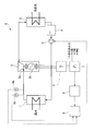
- FIG. 1 is a configuration diagram of a waste heat power generator G in an embodiment of the present invention.
- the waste heat power generation apparatus G of this embodiment includes a Rankine cycle including an evaporator 1, an expansion turbine generator 2 (turbine generator), a condenser 3, a reservoir tank 4 (storage device), and a pump 5. , Which generates power using waste heat energy of low-temperature waste heat (hot water, which may be referred to as a heat source in the present embodiment) released from a factory, an incineration facility, or the like.
- the waste heat power generation apparatus G includes an AC-DC converter 6 and a DC-AC converter 7, and outputs waste heat energy as electric energy (three-phase AC power).
- the waste heat power generation apparatus G is installed in a facility such as a factory, for example, and generates three-phase AC power having the same specifications as commercial power. This three-phase AC power is fed to each part of the facility and consumed. That is, the waste heat power generation apparatus G is installed in the facility in order to improve the overall energy efficiency of the facility.
- the evaporator 1 recovers low-temperature waste heat released from a factory or the like to generate working medium vapor.
- the evaporator 1 is a kind of heat exchanger that vaporizes a working medium by heat exchange with a heat source.
- a flow path through which a heat source for example, hot water
- a working medium circulates so that the heat of the heat source on the high temperature side is on the working medium on the low temperature side.
- Such an evaporator 1 vaporizes the liquid working medium supplied from the pump 5, and supplies the vaporized working medium to the expansion turbine generator 2.
- G the pressure inside the apparatus during operation is 1 MPa (G) at the maximum (1 MPa in gauge pressure).
- the reason for this is that, for example, steam can be generated from low-temperature waste heat to enable power generation using waste heat energy of low-temperature waste heat of about 100 ° C. or less, and the expansion turbine is kept low by keeping the pressure of the entire apparatus low. This is to keep the internal pressure of the generator 2 low.
- HFE hydrofluoroether
- fluorocarbon fluoroketone
- perfluoropolyether or the like can be used as the working medium.
- the expansion turbine generator 2 generates three-phase AC power using the vaporized working medium supplied from the evaporator 1.
- the expansion turbine generator 2 includes a turbine 2a and a generator 2b as shown in the figure.
- the turbine 2 a is a rotating machine that is driven by a working medium supplied from the evaporator 1. That is, the turbine 2a includes a receiving port for receiving the working medium from the evaporator 1, a discharge port for discharging the working medium to the condenser 3, a turbine impeller whose shaft (turbine shaft) is coupled to the generator 2b, and the like. The turbine impeller is rotated by supplying the working medium from the evaporator 1.
- the generator 2b is a rotating machine that is driven by the rotational power of the turbine 2a to generate three-phase AC power. That is, the generator 2b includes a substantially cylindrical rotor (field) that is axially coupled to the turbine shaft of the turbine 2a, and a stator (armature winding) provided in an annular shape around the rotor. Has been. In such a generator 2b, an electromotive force is generated in the stator (armature winding) when the rotor (field) is rotationally driven by the turbine 2a.
- the three-phase AC power output from the generator 2b is different in frequency or / and output voltage from commercial power (system power) specifications.
- the substantially cylindrical rotor means a substantially cylindrical rotor. That is, the substantially cylindrical rotor includes not only a cylindrical rotor but also a rotor that functions in the same manner as a cylindrical rotor, although it is not an accurate cylindrical shape.
- the condenser 3 cools and condenses the steam that has passed through the expansion turbine generator 2 with a cooling medium such as cooling water.
- the condenser 3 is a kind of heat exchanger that condenses (liquefies) a working medium by heat exchange with cooling water.
- Such a condenser 3 supplies a liquid working medium to the reservoir tank 4.
- the reservoir tank 4 is a tank that temporarily stores the working medium condensed by the condenser 3.
- the pump 5 pressurizes the working medium condensed in the condenser 3 and temporarily stored in the reservoir tank 4, and sends it to the evaporator 1.
- the pump 5 is rotationally driven by, for example, an electric motor.
- the AC-DC converter 6 and the DC-AC converter 7 are three-phase AC power (for example, 50/60 Hz, 200 V class) in which the three-phase AC power generated by the generator 2b conforms to the specifications of commercial power (system power). Convert to Of the AC-DC converter 6 and the DC-AC converter 7, the previous-stage AC-DC converter 6 converts the three-phase AC power input from the generator 2 b into DC power and converts it into DC-AC. Output to the converter 7. The subsequent DC-AC converter 7 converts the DC power into three-phase AC power that conforms to the specifications of commercial power (system power).
- the waste heat power generation apparatus G uses the AC-DC converter 6 and the DC-AC converter 7, that is, the power regeneration converter, to generate power per unit time (for example, in seconds) of the expansion turbine generator 2.
- a measurement device (measurement unit) 8 that measures (hereinafter may be simply referred to as a power generation amount) and a control device 9 that controls the driving of the pump 5 based on the measurement result of the measurement device 8 are provided.
- the measuring device 8 is connected to the DC-AC converter 7 (or the AC-DC converter 6), and outputs the measurement result to the control device 9.
- the measuring device 8 has a noise filter so as not to pick up noise of the power generation amount (for example, noise on the order of ⁇ sec).
- the control device 9 confirms the power generation amount (absolute amount) confirmed by the control of the power regeneration converter, and sets predetermined threshold values (specifically, a first threshold value T1, a second threshold value T2, and a second threshold value described later) 3), the drive of the pump 5 is controlled. Further, the control device 9 confirms the slope of the change in the amount of power generation, and when the slope is equal to or greater than a preset condition (specifically, when the slope is equal to or less than a preset negative slope S described later) Then, the drive of the pump 5 is stopped rapidly. In addition, the control apparatus 9 of this embodiment controls an internal cycle so that most electric power generation may be performed in the state of waste heat as usual based on the measurement result of the temperature sensor 9a and the pressure sensor 9b normally.
- predetermined threshold values specifically, a first threshold value T1, a second threshold value T2, and a second threshold value described later
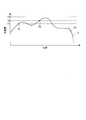
- FIG. 2 is a graph for explaining the control of the pump 5 based on the change in the power generation amount in the embodiment of the present invention.
- the vertical axis indicates the amount of power generation
- the horizontal axis indicates time.
- the working medium is the evaporator 1 ⁇ the expansion turbine generator 2 ⁇ the condenser 3 ⁇ the reservoir tank 4. Electric power is generated in the expansion turbine generator 2 by changing the working medium into liquid and gas while circulating in the order of the pump 5 ⁇ the evaporator 1.
- the working medium evaporated in the evaporator 1 by the heat of the heat source is supplied to the expansion turbine generator 2, condensed in the condenser 3 by the cooling water, temporarily stored in the reservoir tank 4, and then pump 5 again. Is sent to the evaporator 1.
- the expansion turbine generator 2 In the process of the cyclic state change of the working medium, the expansion turbine generator 2 generates power by the action of the working medium.
- the three-phase AC power generated by the expansion turbine generator 2 is converted into three-phase AC power that conforms to the specifications of commercial power (system power) through the AC-DC converter 6 and the DC-AC converter 7. And supplied to the outside.
- the control device 9 calculates the degree of superheat based on the measurement results of the temperature sensor 9 a and the pressure sensor 9 b at normal times, and drives the pump 5 so that the degree of superheat reaches a predetermined target value.
- the internal cycle is controlled so as to generate the most power in the waste heat state as before.
- the control device 9 performs the following control based on the power generation amount per unit time of the expansion turbine generator 2 in an emergency. That is, in this embodiment, the priority based on the amount of power generation is set higher than the control based on the degree of superheat.
- the control device 9 When the power generation amount is equal to or greater than the first threshold value T1 (indicated by reference symbol P1), the control device 9 reduces the amount of working medium delivered per unit time of the pump 5 with a first slope. Specifically, when the power generation amount reaches the threshold value T1, the control device 9 sets a negative acceleration deceleration state in which the rotational speed of the pump 5 is gradually decreased. By this control, the evaporation amount of the working medium in the evaporator 1 is suppressed, and as a result, the power generation amount in the expansion turbine generator 2 can be reduced. When the power generation amount is less than the threshold value T1, the control device 9 switches the mode to normal superheat degree control.
- the control device 9 sets the amount of working medium delivered by the pump 5 per unit time to It is reduced by a second inclination which is larger on the negative side than the inclination of. Specifically, when the power generation amount reaches the next threshold value T2, the control device 9 sets a negative acceleration deceleration state that causes the rotational speed of the pump 5 to drop more rapidly. When the power generation amount becomes less than the threshold value T1, the control device 9 similarly switches the mode to normal superheat degree control.
- the control apparatus 9 stops the drive of the pump 5, when the electric power generation amount becomes more than 3rd threshold value T3 larger than 2nd threshold value T2. That is, the control device 9 immediately stops the pump 5 when the third threshold value T3 that is the final limit threshold value is exceeded.
- the control device 9 provides the first threshold value T1 and the second threshold value T2 on the near side of the third threshold value T3 and performs the deceleration control of the driving of the pump 5, thereby generating a large amount of waste heat and generating electric power. Even in an excessively large state, power generation exceeding the performance of the expansion turbine generator 2 can be suppressed, so that the apparatus can maintain a state in which power can be generated safely.
- control device 9 can reduce the pump 5 when the slope of the change in the amount of power generation is equal to or less than the negative slope S set in advance (indicated by reference symbol P3) even if it is less than the predetermined threshold values T1, T2, T3. Stop driving. That is, the power generation amount per unit time of the expansion turbine generator 2 is relatively more sensitive to fluctuations in the waste heat energy than the temperature and pressure of the working medium. It can be quickly detected from the inclination. For this reason, when the slope of the change in the amount of power generation falls below the setting, the control device 9 determines that power generation is difficult (such as when hot water supply is suddenly stopped) and immediately stops driving the pump 5. To do. Thereby, for example, the pump 5 continues to send the working medium to the evaporator 1, and the occurrence of erosion (erosion) of the turbine impeller due to the liquid working medium being supplied to the expansion turbine generator 2 can be prevented. .
- the lower limit of the power generation amount is set and the threshold control as described above is performed to stop the supply of hot water.
- a time lag of several tens of seconds (a time lag of several tens of seconds or more in the case of temperature and pressure) occurs until the amount of power generation decreases to the lower limit threshold.
- the drive of the pump 5 is controlled based on the slope of the change in the amount of power generation, the fluctuation of the waste heat energy can be reflected in the control of the pump 5 relatively quickly.
- the waste heat power generation apparatus includes the evaporator 1 that recovers waste heat energy and evaporates the working medium, and the expansion turbine generator that generates power by supplying the working medium from the evaporator 1. 2, a condenser 3 that condenses the working medium discharged from the expansion turbine generator 2, a pump 5 that sends the working medium condensed in the condenser 3 toward the evaporator 1, and the expansion turbine generator 2 It has the measuring device 8 which measures the electric power generation amount per unit time, and the control apparatus 9 which controls the drive of the pump 5 based on the measurement result of the measuring device 8. Since this waste heat power generation apparatus G can reflect the fluctuation of waste heat energy rather than the temperature and pressure of the working medium in the control of the pump 5 relatively quickly, it appropriately responds to the sudden fluctuation of waste heat energy. Can work.
- the drive of the pump 5 is stopped when the slope of the change in the amount of power generation is equal to or less than a negative slope set in advance, but the present invention is not limited to this configuration.
- the drive of the pump 5 may be stopped when the slope of the change in the amount of power generation is greater than or equal to a positive slope set in advance (such as when a high-temperature heat source is suddenly supplied).
- the power generation amount is controlled based on a preset threshold value, but the present invention is not limited to this configuration.
- the target power generation can be kept almost constant by changing the threshold value.
- waste heat energy used as warm water was generated as electric energy
- this invention is not limited to this.
- waste gas may be used as a heat source.
- the heat source is not limited to waste heat such as waste gas or waste hot water.
- this invention is applicable also when using radial turbine generators, such as a centrifugal expansion turbine generator and a mixed flow type expansion turbine generator, as an electric power generating apparatus.
- radial turbine generators such as a centrifugal expansion turbine generator and a mixed flow type expansion turbine generator
- the waste heat power generator which can operate
Landscapes
- Engineering & Computer Science (AREA)
- Chemical & Material Sciences (AREA)
- Combustion & Propulsion (AREA)
- Mechanical Engineering (AREA)
- General Engineering & Computer Science (AREA)
- Engine Equipment That Uses Special Cycles (AREA)
- Control Of Turbines (AREA)
- Control Of Positive-Displacement Pumps (AREA)
Abstract
廃熱エネルギーを回収して作動媒体を蒸発させる蒸発器(1)と、蒸発器(1)からの作動媒体の供給により発電を行う膨張タービン発電機(2)と、膨張タービン発電機(2)から排出された作動媒体を凝縮する凝縮器(3)と、凝縮器(3)で凝縮された作動媒体を蒸発器(1)に向けて送出するポンプ(5)と、膨張タービン発電機(2)の単位時間あたりの発電量を計測する計測装置(8)と、計測装置(8)の計測結果に基づいてポンプ(5)の駆動を制御する制御装置(9)と、を有する廃熱発電装置(G)。
Description
本発明は、廃熱発電装置に関し、特にバイナリー発電を行う廃熱発電装置に関する。
本願は、2012年11月28日に日本国に出願された特願2012-259726号に基づき優先権を主張し、その内容をここに援用する。
本願は、2012年11月28日に日本国に出願された特願2012-259726号に基づき優先権を主張し、その内容をここに援用する。
従来から工場や焼却施設等で放出される廃熱エネルギーを回収して発電が行われており、この発電によって得られた電気エネルギーが再利用されることで省エネルギーが図られている。近年では、従来殆ど回収されていなかった低温廃熱の廃熱エネルギーをも回収して発電を行うことで、更なる省エネルギーを実現させる取り組みが行われている。このような低温廃熱から電気エネルギーを回収するために、低沸点作動媒体を用いたランキンサイクルの廃熱発電装置が提案されている(例えば特許文献1)。
特許文献1には、蒸気発生器を備え、排熱源からの排熱媒体を蒸気発生器に導入し、発生した作動媒体蒸気を膨張機に導き、この膨張機で発電機を駆動して発電すると共に、吐出される作動媒体蒸気を凝縮器に導き低熱源からの低熱媒体により作動媒体蒸気を冷却・凝縮し、この凝縮した作動媒体液を蒸気発生器に供給する排熱発電装置が開示されている。この排熱発電装置には、蒸気発生器に供給する作動媒体液流量を増減してこの蒸気発生器の蒸気吐出口又は相当する部分の作動媒体蒸気の過熱度を所定の目標値に制御する作動媒体蒸気過熱度制御手段が設けられている。
しかしながら、上記従来技術には、次のような可能性がある。
通常、廃熱発電装置は、廃熱から最も多くの発電を行うように内部サイクルが制御されており、上記従来技術では、圧力センサ及び温度センサの計測結果から導出される作動媒体蒸気の過熱度を所定の目標値に制御する。ところが、廃熱エネルギーは供給側(工場や焼却施設等)の都合により変動し易く、圧力センサ及び温度センサは、この廃熱エネルギーの変動に対して敏感ではない。従って、例えば蒸発器への廃熱媒体の供給が急停止した場合、ポンプによる蒸発器への作動媒体の送出が継続されて、蒸発器からタービン発電機に液体のまま作動媒体が供給され、タービン発電機のインペラの浸食(エロージョン)を生じさせてしまうことがある。
通常、廃熱発電装置は、廃熱から最も多くの発電を行うように内部サイクルが制御されており、上記従来技術では、圧力センサ及び温度センサの計測結果から導出される作動媒体蒸気の過熱度を所定の目標値に制御する。ところが、廃熱エネルギーは供給側(工場や焼却施設等)の都合により変動し易く、圧力センサ及び温度センサは、この廃熱エネルギーの変動に対して敏感ではない。従って、例えば蒸発器への廃熱媒体の供給が急停止した場合、ポンプによる蒸発器への作動媒体の送出が継続されて、蒸発器からタービン発電機に液体のまま作動媒体が供給され、タービン発電機のインペラの浸食(エロージョン)を生じさせてしまうことがある。
本発明は、上記事情に鑑みてなされたものであり、廃熱エネルギーの急激な変動に適切に対応して動作できる廃熱発電装置の提供を目的とする。
本発明の第1の態様は、廃熱エネルギーを回収して作動媒体を蒸発させる蒸発器と、前記蒸発器からの前記作動媒体の供給により発電を行うタービン発電機と、前記タービン発電機から排出された前記作動媒体を凝縮する凝縮器と、前記凝縮器で凝縮された前記作動媒体を前記蒸発器に向けて送出するポンプと、前記タービン発電機の単位時間あたりの発電量を計測する計測部と、前記計測部の計測結果に基づいて前記ポンプの駆動を制御する制御部と、を有する廃熱発電装置である。
本発明の第1の態様では、タービン発電機の単位時間あたりの発電量に基づいて制御を行うことで、作動媒体の温度や圧力よりも廃熱エネルギーの変動を比較的直ぐにポンプの制御に反映させることができるため、廃熱エネルギーの急激な変動に適切に対応することができる。
本発明の第1の態様では、タービン発電機の単位時間あたりの発電量に基づいて制御を行うことで、作動媒体の温度や圧力よりも廃熱エネルギーの変動を比較的直ぐにポンプの制御に反映させることができるため、廃熱エネルギーの急激な変動に適切に対応することができる。
本発明の第2の態様においては、前記制御部は、前記発電量の変化の傾きに基づいて前記ポンプの駆動を制御する。
本発明の第2の態様では、廃熱エネルギーの急激な変動を発電量の変化の傾きから速やかに察知することができるため、廃熱エネルギーの急激な変動に適切に対応することができる。
本発明の第2の態様では、廃熱エネルギーの急激な変動を発電量の変化の傾きから速やかに察知することができるため、廃熱エネルギーの急激な変動に適切に対応することができる。
本発明の第3の態様においては、前記制御部は、前記発電量の変化の傾きが予め設定された負の傾き以下となった場合に前記ポンプの駆動を停止させる。
本発明の第3の態様では、発電量の変化の傾きが設定より下がった場合、発電が困難な状態であると判断できるため、ポンプの駆動を停止させる。
本発明の第3の態様では、発電量の変化の傾きが設定より下がった場合、発電が困難な状態であると判断できるため、ポンプの駆動を停止させる。
本発明の第4の態様においては、前記制御部は、前記発電量が第1の閾値以上となった場合に前記ポンプの単位時間あたりの前記作動媒体の送出量を第1の傾きで低減させる。
本発明の第4の態様では、発電量が第1の閾値を超えた場合、ポンプの駆動を徐々に落とすように制御することで、タービン発電機の性能を超えた発電を抑えることができる。
本発明の第4の態様では、発電量が第1の閾値を超えた場合、ポンプの駆動を徐々に落とすように制御することで、タービン発電機の性能を超えた発電を抑えることができる。
本発明の第5の態様においては、前記制御部は、前記発電量が前記第1の閾値よりも大きい第2の閾値以上となった場合に前記ポンプの単位時間あたりの前記作動媒体の送出量を前記第1の傾きよりも負側に大きい第2の傾きで低減させる。
本発明の第5の態様では、発電量が第2の閾値を超えた場合、ポンプの駆動をより速く低下させるように制御することで、確実にタービン発電機の性能を超えた発電を抑えることができる。
本発明の第5の態様では、発電量が第2の閾値を超えた場合、ポンプの駆動をより速く低下させるように制御することで、確実にタービン発電機の性能を超えた発電を抑えることができる。
本発明の第6の態様においては、前記制御部は、前記発電量が前記第2の閾値よりも大きい第3の閾値以上となった場合に前記ポンプの駆動を停止させる。
本発明の第6の態様では、発電量が第3の閾値を超えた場合、ポンプの駆動を停止させるように制御することで、より確実にタービン発電機の性能を超えた発電を抑えることができる。
本発明の第6の態様では、発電量が第3の閾値を超えた場合、ポンプの駆動を停止させるように制御することで、より確実にタービン発電機の性能を超えた発電を抑えることができる。
本発明によれば、廃熱エネルギーの急激な変動に適切に対応して動作できる廃熱発電装置が得られる。
以下、図面を参照して、本発明の一実施形態について説明する。
図1は、本発明の実施形態における廃熱発電装置Gの構成図である。
図1に示す通り、本実施形態の廃熱発電装置Gは、蒸発器1、膨張タービン発電機2(タービン発電機)、凝縮器3、リザーバタンク4(貯蔵装置)、ポンプ5を備えるランキンサイクルを利用した発電装置であり、工場や焼却施設等から放出される低温廃熱(本実施形態では温水、以下、熱源と称する場合がある)の廃熱エネルギーを用いて発電を行う。
図1は、本発明の実施形態における廃熱発電装置Gの構成図である。
図1に示す通り、本実施形態の廃熱発電装置Gは、蒸発器1、膨張タービン発電機2(タービン発電機)、凝縮器3、リザーバタンク4(貯蔵装置)、ポンプ5を備えるランキンサイクルを利用した発電装置であり、工場や焼却施設等から放出される低温廃熱(本実施形態では温水、以下、熱源と称する場合がある)の廃熱エネルギーを用いて発電を行う。
また、廃熱発電装置Gは、AC-DC変換器6及びDC-AC変換器7を備え、廃熱エネルギーを電気エネルギー(三相交流電力)として出力する。この廃熱発電装置Gは、例えば工場等の施設に設けられ、商用電力と同仕様の三相交流電力を発電する。
この三相交流電力は、施設の各部に給電されて消費される。すなわち、この廃熱発電装置Gは、施設の全体的なエネルギー効率を向上させるために施設内に備え付けられる。
この三相交流電力は、施設の各部に給電されて消費される。すなわち、この廃熱発電装置Gは、施設の全体的なエネルギー効率を向上させるために施設内に備え付けられる。
蒸発器1は、工場等から放出される低温廃熱を回収して作動媒体の蒸気を生成する。蒸発器1は、熱源との間の熱交換によって作動媒体を気化させる一種の熱交換器である。この蒸発器1では、熱源(例えば温水)が流通する流路と作動媒体が流通する流路とが隣接するように設けられており、高温側である熱源の熱が低温側である作動媒体に効率良く伝導する。このような蒸発器1は、ポンプ5から供給された液体状態の作動媒体を気化させ、気化状態の作動媒体を膨張タービン発電機2に供給する。
本実施形態の作動媒体としては、例えば、沸点(大気圧条件下における沸点)が35℃程度の媒体を用い、且つ運転中の装置内部の圧力が最大で1MPa(G)(ゲージ圧で1MPa)以下であるのが望ましい。その理由は、例えば約100℃以下の低温廃熱の廃熱エネルギーを利用した発電を可能とすべく低温廃熱から蒸気の生成を可能にするとともに、装置全体の圧力を低く抑えることで膨張タービン発電機2の内部圧力を低く抑えるためである。
膨張タービン発電機2の内部圧力が低く抑えられると、膨張タービン発電機2のケーシングや蒸発器1及び凝縮器3にも高い圧力がかからないため、安全でかつコストを低く抑えて製造することも可能となるという相乗的な効果も得られる。ここで、上記の作動媒体としては、ハイドロフルオロエーテル(HFE)、フルオロカーボン、フルオロケトン、パーフルオロポリエーテル等を用いることができる。
膨張タービン発電機2は、このような蒸発器1から供給された気化状態の作動媒体を用いて三相交流電力を発電する。この膨張タービン発電機2は、図示するようにタービン2a、発電機2bを備えている。タービン2aは、蒸発器1から供給される作動媒体によって駆動される回転機械である。すなわち、このタービン2aは、作動媒体を蒸発器1から受け入れる受入口と、作動媒体を凝縮器3に排出する排出口と、軸(タービン軸)が発電機2bと結合するタービンインペラ等を備え、蒸発器1からの作動媒体の供給によってタービンインペラを回転させる。
発電機2bは、タービン2aの回転動力によって駆動されて三相交流電力を発電する回転機械である。すなわち、この発電機2bは、タービン2aのタービン軸と軸結合すると共に略円筒状のロータ(界磁)と、このロータの外周に円環状に備えられたステータ(電機子巻線)等から構成されている。このような発電機2bは、ロータ(界磁)がタービン2aによって回転駆動されることによって、ステータ(電機子巻線)に起電力が発生する。なお、この発電機2bが出力する三相交流電力は、周波数あるいは/及び出力電圧が商用電力(系統電力)の仕様とは異なっている。ここで、略円筒状のロータとは、実質的に円筒状のロータを意味する。すなわち、略円筒状のロータとは、円筒状のロータのみならず、正確な円筒状ではないが、円筒状のロータと同様に機能するロータをも含む。
凝縮器3は、膨張タービン発電機2を介した後の蒸気を冷却水等の冷却媒体にて冷却して凝縮させる。凝縮器3は、冷却水との間の熱交換によって作動媒体を凝縮(液体化)させる一種の熱交換器である。このような凝縮器3は、液体の作動媒体をリザーバタンク4に供給する。リザーバタンク4は、凝縮器3で凝縮された作動媒体を一時的に蓄えるタンクである。ポンプ5は、凝縮器3で凝縮されてリザーバタンク4に一時的に蓄えられた作動媒体を加圧して蒸発器1に向けて送出する。なお、このポンプ5は、例えば電動機によって回転駆動される。
AC-DC変換器6及びDC-AC変換器7は、発電機2bが発電した三相交流電力を商用電力(系統電力)の仕様に適合した三相交流電力(例えば50/60Hz,200V級)に変換する。このようなAC-DC変換器6及びDC-AC変換器7のうち、前段のAC-DC変換器6は、発電機2bから入力された三相交流電力を直流電力に変換してDC-AC変換器7に出力する。後段のDC-AC変換器7は、上記直流電力を商用電力(系統電力)の仕様に適合した三相交流電力に変換する。
本実施形態の廃熱発電装置Gは、AC-DC変換器6及びDC-AC変換器7、すなわち電源回生コンバータを介して、膨張タービン発電機2の単位時間(例えば秒単位)当りの発電量(以下、単に発電量と称する場合がある)を計測する計測装置(計測部)8と、計測装置8の計測結果に基づいてポンプ5の駆動を制御する制御装置9と、を備えている。計測装置8は、DC-AC変換器7(AC-DC変換器6でもよい)に接続され、その計測結果を制御装置9に出力する。なお、計測装置8は、発電量のノイズ(例えばμsecオーダーのノイズ)を拾うことのないようノイズフィルターを有する。
制御装置9は、電源回生コンバータの制御で確認している発電量(絶対量)を確認し、予め設定された閾値(具体的には後述する第1の閾値T1、第2の閾値T2、第3の閾値T3、図2参照)に応じて、ポンプ5の駆動を制御する。
また、制御装置9は、発電量の変化の傾きを確認し、予め設定された条件以上の傾きになった場合(具体的には後述する予め設定された負の傾きS以下になった場合)、ポンプ5の駆動を急速に停止させる。
なお、本実施形態の制御装置9は、通常時は温度センサ9a及び圧力センサ9bの計測結果に基づいて従来通り廃熱の状態で最も多くの発電を行うように内部サイクルを制御する。
また、制御装置9は、発電量の変化の傾きを確認し、予め設定された条件以上の傾きになった場合(具体的には後述する予め設定された負の傾きS以下になった場合)、ポンプ5の駆動を急速に停止させる。
なお、本実施形態の制御装置9は、通常時は温度センサ9a及び圧力センサ9bの計測結果に基づいて従来通り廃熱の状態で最も多くの発電を行うように内部サイクルを制御する。
次に、このように構成された廃熱発電装置Gの動作について図2を参照して説明する。
図2は、本発明の実施形態における発電量の変化に基づくポンプ5の制御を説明するためのグラフである。なお、図2において、縦軸は発電量を、横軸は時間を示す。
図2は、本発明の実施形態における発電量の変化に基づくポンプ5の制御を説明するためのグラフである。なお、図2において、縦軸は発電量を、横軸は時間を示す。
最初に、廃熱発電装置Gの発電動作(主動作)について説明すると、本実施形態の廃熱発電装置Gでは、作動媒体が蒸発器1→膨張タービン発電機2→凝縮器3→リザーバタンク4→ポンプ5→蒸発器1の順で循環しつつ作動媒体が液体と気体に変化することによって膨張タービン発電機2における発電が行われる。
すなわち、熱源の熱によって蒸発器1で蒸発した作動媒体は、膨張タービン発電機2に供給された後に凝縮器3で冷却水によって凝縮されて、リザーバタンク4に一時貯溜された後、再びポンプ5を介して蒸発器1に送出される。このような作動媒体の循環的な状態変化の過程において、作動媒体の作用によって膨張タービン発電機2で発電が行われる。
そして、膨張タービン発電機2で発生した三相交流電力は、AC-DC変換器6及びDC-AC変換器7を経ることによって商用電力(系統電力)の仕様に適合した三相交流電力に変換されて外部に供給される。
そして、膨張タービン発電機2で発生した三相交流電力は、AC-DC変換器6及びDC-AC変換器7を経ることによって商用電力(系統電力)の仕様に適合した三相交流電力に変換されて外部に供給される。
図2に示すように、制御装置9は、通常時、温度センサ9a及び圧力センサ9bの計測結果に基づいて過熱度を算出し、この過熱度が所定の目標値となるようポンプ5の駆動を制御することにより、従来通り廃熱の状態で最も多くの発電を行うように内部サイクルを制御する。また、制御装置9は、非常時には、膨張タービン発電機2の単位時間当たりの発電量に基づいて、次のような制御を行う。すなわち、本実施形態では、過熱度に基づく制御よりも、発電量に基づく制御の方が、優先度が高く設定されている。
制御装置9は、発電量が第1の閾値T1以上となった場合(符号P1で示す)、ポンプ5の単位時間当たりの作動媒体の送出量を第1の傾きで低減させる。具体的に、制御装置9は、発電量が閾値T1になると、ポンプ5の回転速度を徐々に落とすような負の加速度の減速状態とする。この制御により、蒸発器1における作動媒体の蒸発量が抑えられ、結果、膨張タービン発電機2における発電量を低下させることができる。なお、発電量が閾値T1未満となった場合には、制御装置9は、通常の過熱度制御にモードを切り替える。
また、制御装置9は、発電量が第1の閾値T1よりも大きい第2の閾値T2以上となった場合(符号P2で示す)、ポンプ5の単位時間当たりの作動媒体の送出量を第1の傾きよりも負側に大きい第2の傾きで低減させる。具体的に、制御装置9は、発電量が次の閾値T2になると、ポンプ5の回転速度をより速く落とすような負の加速度の減速状態とする。なお、発電量が閾値T1未満となった場合には、同様に制御装置9は、通常の過熱度制御にモードを切り替える。
また、制御装置9は、発電量が第2の閾値T2よりも大きい第3の閾値T3以上となった場合には、ポンプ5の駆動を停止させる。すなわち、制御装置9は、最終的な限界閾値である第3の閾値T3を超える場合、ポンプ5を即停止する。このようにすることで、廃熱エネルギーが過大に供給された場合であっても、膨張タービン発電機2が限界を超えて駆動してしまうことを防止できる。また、制御装置9は、第3の閾値T3の手前側で、第1の閾値T1及び第2の閾値T2を設けてポンプ5の駆動の減速制御を行うことで、廃熱量が多く、発電しすぎる状態であっても、膨張タービン発電機2の性能を超えた発電を抑えることができるため、装置が安全に発電できる状態を保てるようになる。
また、制御装置9は、所定の閾値T1,T2,T3未満であっても、発電量の変化の傾きが予め設定された負の傾きS以下となった場合(符号P3で示す)にポンプ5の駆動を停止させる。すなわち、膨張タービン発電機2の単位時間当りの発電量は、作動媒体の温度や圧力よりも廃熱エネルギーの変動に比較的敏感であり、廃熱エネルギーの急激な変動を、発電量の変化の傾きから速やかに察知することができる。このため、制御装置9は、発電量の変化の傾きが設定より下がった場合は、発電が困難な状態(温水の供給が急停止した等)であると判断し、ポンプ5の駆動を即停止する。これにより、例えばポンプ5が作動媒体を蒸発器1に送り続けて、膨張タービン発電機2に液体状態の作動媒体が供給されることによるタービンインペラの浸食(エロージョン)の発生を防止することができる。
なお、発電量は、作動媒体の温度や圧力よりも廃熱エネルギーの変動に比較的敏感であるため、発電量の下限を設定して、上述したような閾値制御を行って温水の供給停止状態に対応させてもよいが、この下限の閾値まで発電量が低下するまでは、例えば十数秒のタイムラグ(なお、温度、圧力の場合は数十秒以上のタイムラグ)が生じる。この点、上述したように、発電量の変化の傾きに基づいてポンプ5の駆動を制御すれば、廃熱エネルギーの変動を比較的直ぐにポンプ5の制御に反映させることができるため、廃熱エネルギーの急激な変動に適切に対応することができる。例えば上述のように供給側の都合で熱源となる温水の供給が急停止した状態であっても、その廃熱エネルギーの急激な変動に適切に対応してポンプ5の駆動を速やかに停止させ、膨張タービン発電機2に液体状態の作動媒体が供給されないようにすることができる。
このように、上述の本実施形態の廃熱発電装置は、廃熱エネルギーを回収して作動媒体を蒸発させる蒸発器1と、蒸発器1からの作動媒体の供給により発電を行う膨張タービン発電機2と、膨張タービン発電機2から排出された作動媒体を凝縮する凝縮器3と、凝縮器3で凝縮された作動媒体を蒸発器1に向けて送出するポンプ5と、膨張タービン発電機2の単位時間あたりの発電量を計測する計測装置8と、計測装置8の計測結果に基づいてポンプ5の駆動を制御する制御装置9と、を有する。この廃熱発電装置Gは、作動媒体の温度や圧力よりも廃熱エネルギーの変動を比較的直ぐにポンプ5の制御に反映させることができるため、廃熱エネルギーの急激な変動に適切に対応して動作できる。
以上、図面を参照しながら本発明の好適な実施形態について説明したが、本発明は上記実施形態に限定されない。上述した実施形態において示した各構成部材の諸形状や組み合わせ等は一例であって、本発明の主旨から逸脱しない範囲において設計要求等に基づき種々変更可能である。
例えば、上記実施形態では、発電量の変化の傾きが予め設定された負の傾き以下となった場合にポンプ5の駆動を停止させると説明したが、本発明はこの構成に限定されない。例えば発電量の変化の傾きが予め設定された正の傾き以上となった場合(急激に高温の熱源が供給された場合等)にポンプ5の駆動を停止させてもよい。
また、例えば、上記実施形態では、予め設定された閾値に基づいて発電量を制御すると説明したが、本発明はこの構成に限定されない。例えばデマンド制御を行う必要がある場合、閾値を変更することで、目標の発電をほぼ一定に保つこともできる。
また、例えば、上記実施形態では、温水となった廃熱エネルギーを電気エネルギーとして発電したが、本発明はこれに限定されない。例えば熱源として廃ガスを用いてもよい。また、熱源は、廃ガスや廃温水などの廃熱に限定されない。
また、例えば、上記実施形態では、本発明は、遠心式膨張タービン発電機、斜流式膨張タービン発電機等のラジアルタービン発電機を発電装置として用いる場合にも適用可能である。
本発明によれば、廃熱エネルギーの急激な変動に適切に対応して動作できる廃熱発電装置が得られる。
1 蒸発器
2 膨張タービン発電機(タービン発電機)
3 凝縮器
5 ポンプ
8 計測装置(計測部)
9 制御装置(制御部)
G 廃熱発電装置
S 負の傾き
T1 第1の閾値
T2 第2の閾値
T3 第3の閾値
2 膨張タービン発電機(タービン発電機)
3 凝縮器
5 ポンプ
8 計測装置(計測部)
9 制御装置(制御部)
G 廃熱発電装置
S 負の傾き
T1 第1の閾値
T2 第2の閾値
T3 第3の閾値
Claims (6)
- 廃熱エネルギーを回収して作動媒体を蒸発させる蒸発器と、前記蒸発器からの前記作動媒体の供給により発電を行うタービン発電機と、前記タービン発電機から排出された前記作動媒体を凝縮する凝縮器と、前記凝縮器で凝縮された前記作動媒体を前記蒸発器に向けて送出するポンプと、
前記タービン発電機の単位時間あたりの発電量を計測する計測部と、
前記計測部の計測結果に基づいて前記ポンプの駆動を制御する制御部と、を有する廃熱発電装置。 - 前記制御部は、前記発電量の変化の傾きに基づいて前記ポンプの駆動を制御する請求項1に記載の廃熱発電装置。
- 前記制御部は、前記発電量の変化の傾きが予め設定された負の傾き以下となった場合に前記ポンプの駆動を停止させる請求項2に記載の廃熱発電装置。
- 前記制御部は、前記発電量が第1の閾値以上となった場合に前記ポンプの単位時間あたりの前記作動媒体の送出量を第1の傾きで低減させる請求項1~3のいずれか一項に記載の廃熱発電装置。
- 前記制御部は、前記発電量が前記第1の閾値よりも大きい第2の閾値以上となった場合に前記ポンプの単位時間あたりの前記作動媒体の送出量を前記第1の傾きよりも負側に大きい第2の傾きで低減させる請求項4に記載の廃熱発電装置。
- 前記制御部は、前記発電量が前記第2の閾値よりも大きい第3の閾値以上となった場合に前記ポンプの駆動を停止させる請求項5に記載の廃熱発電装置。
Priority Applications (1)
| Application Number | Priority Date | Filing Date | Title |
|---|---|---|---|
| US14/710,276 US9784138B2 (en) | 2012-11-28 | 2015-05-12 | Waste heat power generation device |
Applications Claiming Priority (2)
| Application Number | Priority Date | Filing Date | Title |
|---|---|---|---|
| JP2012259726A JP6064548B2 (ja) | 2012-11-28 | 2012-11-28 | 廃熱発電装置 |
| JP2012-259726 | 2012-11-28 |
Related Child Applications (1)
| Application Number | Title | Priority Date | Filing Date |
|---|---|---|---|
| US14/710,276 Continuation US9784138B2 (en) | 2012-11-28 | 2015-05-12 | Waste heat power generation device |
Publications (1)
| Publication Number | Publication Date |
|---|---|
| WO2014084013A1 true WO2014084013A1 (ja) | 2014-06-05 |
Family
ID=50827659
Family Applications (1)
| Application Number | Title | Priority Date | Filing Date |
|---|---|---|---|
| PCT/JP2013/079988 Ceased WO2014084013A1 (ja) | 2012-11-28 | 2013-11-06 | 廃熱発電装置 |
Country Status (4)
| Country | Link |
|---|---|
| US (1) | US9784138B2 (ja) |
| JP (1) | JP6064548B2 (ja) |
| TW (1) | TWI567290B (ja) |
| WO (1) | WO2014084013A1 (ja) |
Cited By (1)
| Publication number | Priority date | Publication date | Assignee | Title |
|---|---|---|---|---|
| JP2018127942A (ja) * | 2017-02-08 | 2018-08-16 | 株式会社神戸製鋼所 | バイナリ発電システム及びその停止方法 |
Families Citing this family (9)
| Publication number | Priority date | Publication date | Assignee | Title |
|---|---|---|---|---|
| JP6233783B2 (ja) * | 2013-09-20 | 2017-11-22 | パナソニックIpマネジメント株式会社 | 発電制御装置、発電装置及びランキンサイクル装置の制御方法 |
| JP6394862B2 (ja) * | 2014-07-02 | 2018-09-26 | 株式会社Ihi回転機械エンジニアリング | 廃熱発電装置 |
| JP6398117B2 (ja) * | 2014-08-21 | 2018-10-03 | 株式会社Ihi回転機械エンジニアリング | 廃熱発電装置 |
| EP3301267A1 (de) * | 2016-09-29 | 2018-04-04 | Siemens Aktiengesellschaft | Verfahren und vorrichtung zum betreiben eines turbosatzes |
| CN106762647A (zh) * | 2016-12-30 | 2017-05-31 | 温岭市鑫磊空压机有限公司 | 一种余热利用节能型空气压缩机 |
| CN107248720B (zh) * | 2017-08-16 | 2023-06-27 | 国网湖南省电力公司 | 具有余热发电功能的集约型直流融冰装置及其控制方法 |
| JP6941076B2 (ja) * | 2018-06-05 | 2021-09-29 | 株式会社神戸製鋼所 | 発電方法 |
| CN113530627A (zh) * | 2021-07-15 | 2021-10-22 | 安徽绿洲危险废物综合利用有限公司 | 一种再生铜冶炼过程余热再利用系统 |
| US11976574B2 (en) * | 2021-12-22 | 2024-05-07 | Charles Tuckey | Closed loop steam engine assembly with feedback features and method of operation |
Citations (5)
| Publication number | Priority date | Publication date | Assignee | Title |
|---|---|---|---|---|
| JPH0882203A (ja) * | 1994-09-14 | 1996-03-26 | Toshiba Corp | 発電プラントの運転制御装置 |
| JPH0932508A (ja) * | 1995-07-24 | 1997-02-04 | Hitachi Ltd | コンバインドサイクルプラント |
| JPH1136818A (ja) * | 1997-07-18 | 1999-02-09 | Toshiba Corp | 排熱利用複合発電プラントの制御装置 |
| JP2009221961A (ja) * | 2008-03-17 | 2009-10-01 | Fuji Electric Holdings Co Ltd | バイナリー発電システム |
| JP2011214430A (ja) * | 2010-03-31 | 2011-10-27 | Kobe Steel Ltd | 発電装置及び発電装置の運転方法 |
Family Cites Families (5)
| Publication number | Priority date | Publication date | Assignee | Title |
|---|---|---|---|---|
| JPS5949303A (ja) * | 1982-09-13 | 1984-03-21 | Hitachi Ltd | 熱動機関における出力制御システム |
| US7860206B2 (en) * | 2006-02-27 | 2010-12-28 | Hitachi-Ge Nuclear Energy, Ltd. | Reactor power control apparatus of a natural circulation boiling water reactor and a feed water control apparatus and nuclear power generation plant |
| JP4281770B2 (ja) * | 2006-08-31 | 2009-06-17 | 株式会社日立製作所 | ヒートポンプシステム |
| JP4875546B2 (ja) | 2007-06-13 | 2012-02-15 | 株式会社荏原製作所 | 排熱発電装置、排熱発電装置の作動媒体蒸気過熱度制御方法 |
| JP5192736B2 (ja) * | 2007-06-13 | 2013-05-08 | 株式会社荏原製作所 | 排熱発電装置、排熱発電装置の運転方法 |
-
2012
- 2012-11-28 JP JP2012259726A patent/JP6064548B2/ja active Active
-
2013
- 2013-11-06 WO PCT/JP2013/079988 patent/WO2014084013A1/ja not_active Ceased
- 2013-11-20 TW TW102142221A patent/TWI567290B/zh not_active IP Right Cessation
-
2015
- 2015-05-12 US US14/710,276 patent/US9784138B2/en not_active Expired - Fee Related
Patent Citations (5)
| Publication number | Priority date | Publication date | Assignee | Title |
|---|---|---|---|---|
| JPH0882203A (ja) * | 1994-09-14 | 1996-03-26 | Toshiba Corp | 発電プラントの運転制御装置 |
| JPH0932508A (ja) * | 1995-07-24 | 1997-02-04 | Hitachi Ltd | コンバインドサイクルプラント |
| JPH1136818A (ja) * | 1997-07-18 | 1999-02-09 | Toshiba Corp | 排熱利用複合発電プラントの制御装置 |
| JP2009221961A (ja) * | 2008-03-17 | 2009-10-01 | Fuji Electric Holdings Co Ltd | バイナリー発電システム |
| JP2011214430A (ja) * | 2010-03-31 | 2011-10-27 | Kobe Steel Ltd | 発電装置及び発電装置の運転方法 |
Cited By (2)
| Publication number | Priority date | Publication date | Assignee | Title |
|---|---|---|---|---|
| JP2018127942A (ja) * | 2017-02-08 | 2018-08-16 | 株式会社神戸製鋼所 | バイナリ発電システム及びその停止方法 |
| WO2018147027A1 (ja) * | 2017-02-08 | 2018-08-16 | 株式会社神戸製鋼所 | バイナリ発電システム及びその停止方法 |
Also Published As
| Publication number | Publication date |
|---|---|
| JP2014105643A (ja) | 2014-06-09 |
| US20150247427A1 (en) | 2015-09-03 |
| TW201432134A (zh) | 2014-08-16 |
| JP6064548B2 (ja) | 2017-01-25 |
| TWI567290B (zh) | 2017-01-21 |
| US9784138B2 (en) | 2017-10-10 |
Similar Documents
| Publication | Publication Date | Title |
|---|---|---|
| JP6064548B2 (ja) | 廃熱発電装置 | |
| CN106593554B (zh) | 朗肯循环发电装置 | |
| US9677414B2 (en) | Waste heat power generator | |
| EP2540995B1 (en) | Power generation apparatus | |
| JP6092723B2 (ja) | 蒸気タービンプラントの起動制御装置 | |
| US9966756B2 (en) | Thermal power generation apparatus and thermal power generation system | |
| JP6398117B2 (ja) | 廃熱発電装置 | |
| JP4684762B2 (ja) | 発電装置 | |
| US11035258B2 (en) | Model-based monitoring of the operating state of an expansion machine | |
| JP6458407B2 (ja) | 廃熱発電装置 | |
| JP4684761B2 (ja) | 発電装置 | |
| JP6860351B2 (ja) | ランキンサイクルの制御装置 | |
| JP7587871B2 (ja) | Orc発電装置 | |
| JP2014530314A (ja) | 改良されたorc熱エンジン | |
| JP2014239604A (ja) | 発電装置 |
Legal Events
| Date | Code | Title | Description |
|---|---|---|---|
| 121 | Ep: the epo has been informed by wipo that ep was designated in this application |
Ref document number: 13859298 Country of ref document: EP Kind code of ref document: A1 |
|
| NENP | Non-entry into the national phase |
Ref country code: DE |
|
| 122 | Ep: pct application non-entry in european phase |
Ref document number: 13859298 Country of ref document: EP Kind code of ref document: A1 |