WO2014080848A1 - 発電システム及び発電システムの運転方法 - Google Patents
発電システム及び発電システムの運転方法 Download PDFInfo
- Publication number
- WO2014080848A1 WO2014080848A1 PCT/JP2013/080925 JP2013080925W WO2014080848A1 WO 2014080848 A1 WO2014080848 A1 WO 2014080848A1 JP 2013080925 W JP2013080925 W JP 2013080925W WO 2014080848 A1 WO2014080848 A1 WO 2014080848A1
- Authority
- WO
- WIPO (PCT)
- Prior art keywords
- fuel gas
- exhaust
- exhaust fuel
- supplied
- gas
- Prior art date
- Legal status (The legal status is an assumption and is not a legal conclusion. Google has not performed a legal analysis and makes no representation as to the accuracy of the status listed.)
- Ceased
Links
Images




Classifications
-
- H—ELECTRICITY
- H01—ELECTRIC ELEMENTS
- H01M—PROCESSES OR MEANS, e.g. BATTERIES, FOR THE DIRECT CONVERSION OF CHEMICAL ENERGY INTO ELECTRICAL ENERGY
- H01M8/00—Fuel cells; Manufacture thereof
- H01M8/06—Combination of fuel cells with means for production of reactants or for treatment of residues
- H01M8/0662—Treatment of gaseous reactants or gaseous residues, e.g. cleaning
-
- F—MECHANICAL ENGINEERING; LIGHTING; HEATING; WEAPONS; BLASTING
- F02—COMBUSTION ENGINES; HOT-GAS OR COMBUSTION-PRODUCT ENGINE PLANTS
- F02C—GAS-TURBINE PLANTS; AIR INTAKES FOR JET-PROPULSION PLANTS; CONTROLLING FUEL SUPPLY IN AIR-BREATHING JET-PROPULSION PLANTS
- F02C3/00—Gas-turbine plants characterised by the use of combustion products as the working fluid
- F02C3/20—Gas-turbine plants characterised by the use of combustion products as the working fluid using a special fuel, oxidant, or dilution fluid to generate the combustion products
- F02C3/22—Gas-turbine plants characterised by the use of combustion products as the working fluid using a special fuel, oxidant, or dilution fluid to generate the combustion products the fuel or oxidant being gaseous at standard temperature and pressure
-
- F—MECHANICAL ENGINEERING; LIGHTING; HEATING; WEAPONS; BLASTING
- F02—COMBUSTION ENGINES; HOT-GAS OR COMBUSTION-PRODUCT ENGINE PLANTS
- F02C—GAS-TURBINE PLANTS; AIR INTAKES FOR JET-PROPULSION PLANTS; CONTROLLING FUEL SUPPLY IN AIR-BREATHING JET-PROPULSION PLANTS
- F02C6/00—Plural gas-turbine plants; Combinations of gas-turbine plants with other apparatus; Adaptations of gas-turbine plants for special use
-
- F—MECHANICAL ENGINEERING; LIGHTING; HEATING; WEAPONS; BLASTING
- F02—COMBUSTION ENGINES; HOT-GAS OR COMBUSTION-PRODUCT ENGINE PLANTS
- F02C—GAS-TURBINE PLANTS; AIR INTAKES FOR JET-PROPULSION PLANTS; CONTROLLING FUEL SUPPLY IN AIR-BREATHING JET-PROPULSION PLANTS
- F02C6/00—Plural gas-turbine plants; Combinations of gas-turbine plants with other apparatus; Adaptations of gas-turbine plants for special use
- F02C6/18—Plural gas-turbine plants; Combinations of gas-turbine plants with other apparatus; Adaptations of gas-turbine plants for special use using the waste heat of gas-turbine plants outside the plants themselves, e.g. gas-turbine power heat plants
-
- H—ELECTRICITY
- H01—ELECTRIC ELEMENTS
- H01M—PROCESSES OR MEANS, e.g. BATTERIES, FOR THE DIRECT CONVERSION OF CHEMICAL ENERGY INTO ELECTRICAL ENERGY
- H01M8/00—Fuel cells; Manufacture thereof
- H01M8/04—Auxiliary arrangements, e.g. for control of pressure or for circulation of fluids
- H01M8/04007—Auxiliary arrangements, e.g. for control of pressure or for circulation of fluids related to heat exchange
- H01M8/04014—Heat exchange using gaseous fluids; Heat exchange by combustion of reactants
- H01M8/04022—Heating by combustion
-
- H—ELECTRICITY
- H01—ELECTRIC ELEMENTS
- H01M—PROCESSES OR MEANS, e.g. BATTERIES, FOR THE DIRECT CONVERSION OF CHEMICAL ENERGY INTO ELECTRICAL ENERGY
- H01M8/00—Fuel cells; Manufacture thereof
- H01M8/04—Auxiliary arrangements, e.g. for control of pressure or for circulation of fluids
- H01M8/04298—Processes for controlling fuel cells or fuel cell systems
- H01M8/04694—Processes for controlling fuel cells or fuel cell systems characterised by variables to be controlled
- H01M8/04746—Pressure; Flow
- H01M8/04761—Pressure; Flow of fuel cell exhausts
-
- H—ELECTRICITY
- H01—ELECTRIC ELEMENTS
- H01M—PROCESSES OR MEANS, e.g. BATTERIES, FOR THE DIRECT CONVERSION OF CHEMICAL ENERGY INTO ELECTRICAL ENERGY
- H01M8/00—Fuel cells; Manufacture thereof
- H01M8/10—Fuel cells with solid electrolytes
- H01M8/12—Fuel cells with solid electrolytes operating at high temperature, e.g. with stabilised ZrO2 electrolyte
- H01M2008/1293—Fuel cells with solid oxide electrolytes
-
- H—ELECTRICITY
- H01—ELECTRIC ELEMENTS
- H01M—PROCESSES OR MEANS, e.g. BATTERIES, FOR THE DIRECT CONVERSION OF CHEMICAL ENERGY INTO ELECTRICAL ENERGY
- H01M2250/00—Fuel cells for particular applications; Specific features of fuel cell system
- H01M2250/10—Fuel cells in stationary systems, e.g. emergency power source in plant
-
- H—ELECTRICITY
- H01—ELECTRIC ELEMENTS
- H01M—PROCESSES OR MEANS, e.g. BATTERIES, FOR THE DIRECT CONVERSION OF CHEMICAL ENERGY INTO ELECTRICAL ENERGY
- H01M2250/00—Fuel cells for particular applications; Specific features of fuel cell system
- H01M2250/40—Combination of fuel cells with other energy production systems
- H01M2250/402—Combination of fuel cell with other electric generators
-
- H—ELECTRICITY
- H01—ELECTRIC ELEMENTS
- H01M—PROCESSES OR MEANS, e.g. BATTERIES, FOR THE DIRECT CONVERSION OF CHEMICAL ENERGY INTO ELECTRICAL ENERGY
- H01M2250/00—Fuel cells for particular applications; Specific features of fuel cell system
- H01M2250/40—Combination of fuel cells with other energy production systems
- H01M2250/405—Cogeneration of heat or hot water
-
- Y—GENERAL TAGGING OF NEW TECHNOLOGICAL DEVELOPMENTS; GENERAL TAGGING OF CROSS-SECTIONAL TECHNOLOGIES SPANNING OVER SEVERAL SECTIONS OF THE IPC; TECHNICAL SUBJECTS COVERED BY FORMER USPC CROSS-REFERENCE ART COLLECTIONS [XRACs] AND DIGESTS
- Y02—TECHNOLOGIES OR APPLICATIONS FOR MITIGATION OR ADAPTATION AGAINST CLIMATE CHANGE
- Y02B—CLIMATE CHANGE MITIGATION TECHNOLOGIES RELATED TO BUILDINGS, e.g. HOUSING, HOUSE APPLIANCES OR RELATED END-USER APPLICATIONS
- Y02B90/00—Enabling technologies or technologies with a potential or indirect contribution to GHG emissions mitigation
- Y02B90/10—Applications of fuel cells in buildings
-
- Y—GENERAL TAGGING OF NEW TECHNOLOGICAL DEVELOPMENTS; GENERAL TAGGING OF CROSS-SECTIONAL TECHNOLOGIES SPANNING OVER SEVERAL SECTIONS OF THE IPC; TECHNICAL SUBJECTS COVERED BY FORMER USPC CROSS-REFERENCE ART COLLECTIONS [XRACs] AND DIGESTS
- Y02—TECHNOLOGIES OR APPLICATIONS FOR MITIGATION OR ADAPTATION AGAINST CLIMATE CHANGE
- Y02E—REDUCTION OF GREENHOUSE GAS [GHG] EMISSIONS, RELATED TO ENERGY GENERATION, TRANSMISSION OR DISTRIBUTION
- Y02E20/00—Combustion technologies with mitigation potential
- Y02E20/16—Combined cycle power plant [CCPP], or combined cycle gas turbine [CCGT]
-
- Y—GENERAL TAGGING OF NEW TECHNOLOGICAL DEVELOPMENTS; GENERAL TAGGING OF CROSS-SECTIONAL TECHNOLOGIES SPANNING OVER SEVERAL SECTIONS OF THE IPC; TECHNICAL SUBJECTS COVERED BY FORMER USPC CROSS-REFERENCE ART COLLECTIONS [XRACs] AND DIGESTS
- Y02—TECHNOLOGIES OR APPLICATIONS FOR MITIGATION OR ADAPTATION AGAINST CLIMATE CHANGE
- Y02E—REDUCTION OF GREENHOUSE GAS [GHG] EMISSIONS, RELATED TO ENERGY GENERATION, TRANSMISSION OR DISTRIBUTION
- Y02E60/00—Enabling technologies; Technologies with a potential or indirect contribution to GHG emissions mitigation
- Y02E60/30—Hydrogen technology
- Y02E60/50—Fuel cells
Definitions
- the present invention relates to a power generation system that combines a solid oxide fuel cell, a gas turbine, and a steam turbine, and a method for operating the power generation system.
- Solid oxide fuel cells Solid Oxide Fuel Cells: hereinafter referred to as SOFC
- SOFC Solid Oxide Fuel Cells
- this SOFC has a high operating temperature in order to increase ionic conductivity, compressed air discharged from the compressor of the gas turbine can be used as air (oxidant) supplied to the air electrode side. Further, the high-temperature exhaust fuel gas exhausted from the SOFC can be used as fuel for the combustor of the gas turbine.
- Patent Document 1 various types of power generation systems that can achieve high-efficiency power generation have been proposed in which SOFCs, gas turbines, and steam turbines are combined.
- the gas turbine includes a compressor that compresses air and supplies the compressed fuel to the SOFC, and a combustor that generates combustion gas from the exhaust fuel gas exhausted from the SOFC and the compressed air. I have it.
- the components of the exhaust fuel gas exhausted from the SOFC for a certain period after the fuel gas supply to the SOFC is started are not stable when the SOFC is activated. Therefore, during this period, it becomes difficult to supply exhaust fuel gas to the combustor.
- the required fuel calories vary depending on the output of the gas turbine. When the required calorie of fuel fluctuates, the amount of exhaust fuel gas to be input also fluctuates. Therefore, exhaust fuel gas that cannot be supplied to the combustor is generated, and the exhaust fuel gas cannot be used efficiently.
- the present invention solves the above-described problems, and an object thereof is to provide a power generation system and an operation method of the power generation system that can efficiently use the exhaust fuel gas discharged from the fuel cell.
- a power generation system includes a gas turbine having a compressor and a combustor, a fuel cell, and an exhaust fuel gas for supplying exhaust gas discharged from the fuel cell to the gas turbine.
- a control unit for controlling a supply destination of the exhaust fuel gas discharged from the vehicle.
- the heating means by providing the heating means, the exhaust fuel gas that is not supplied to the gas turbine by the heating means can be fueled. Thereby, the exhaust fuel gas discharged
- the power generation system of the present invention further includes a heat exchanger that recovers heat contained in the exhaust gas discharged from the gas turbine, and the heating means burns the exhaust fuel gas and supplies the exhaust gas to the heat exchanger
- An exhaust gas heating unit for heating the exhaust gas is included.
- the amount of heat that can be recovered by the heat exchanger can be increased.
- emitted from a fuel cell can be utilized efficiently.
- the heating means includes a steam generation unit that generates steam supplied to the fuel gas supplied to the fuel cell by burning the exhaust fuel gas.
- the heating means includes an air heating unit that heats the air supplied to the fuel cell by burning the exhaust fuel gas.
- the heating means includes a fuel gas heating unit that heats the fuel gas that is burned into the exhaust fuel gas and supplied to the fuel cell.
- the fuel can be heated by burning the exhaust fuel gas. Further, the heat contained in the heated air can be used for power generation. Thereby, the exhaust fuel gas discharged
- the power generation system of the present invention has a state detection unit that detects the state of the exhaust fuel gas upstream of the exhaust fuel gas discharge line, and based on the result detected by the state detection unit, When it is determined that the state is stable, the supply of the exhaust fuel gas to the gas turbine is started.
- the exhaust fuel gas in a stable state can be supplied to the gas turbine.
- a gas turbine can be operated efficiently and control can be simplified.
- the exhaust fuel gas whose state is not stable can be utilized by the heating means, the exhaust fuel gas can be effectively utilized.
- the power generation system of the present invention includes a flow rate detection unit that detects a flow rate of exhaust fuel gas supplied from the fuel cell to the exhaust fuel gas supply line and the exhaust fuel gas discharge line, and the control unit includes the flow rate The flow rate of the exhaust fuel gas supplied to the exhaust fuel gas supply line and the flow rate of the exhaust fuel gas supplied to the exhaust fuel gas discharge line are controlled based on the detection result of the detection unit.
- exhaust fuel gas that is not supplied to the gas turbine can be supplied to the heating means. Therefore, it can suppress that excess exhaust fuel gas is supplied to a gas turbine, can operate
- the power generation system operating method of the present invention is a power generation system operating method including a gas turbine having a compressor and a combustor, a fuel cell, and heating means for combusting exhaust fuel gas to heat a heating target. And detecting the state of the exhaust fuel gas discharged from the fuel cell toward the gas turbine, and the exhaust fuel gas not supplied to the gas turbine based on the detected state of the exhaust fuel gas. And a step of supplying the exhaust fuel gas to the heating means when it is determined that there is an exhaust fuel gas that is not supplied to the gas turbine.
- the exhaust fuel gas not supplied to the gas turbine can be fueled by the heating means.
- emitted from a fuel cell can be utilized efficiently.
- the exhaust fuel gas not supplied to the gas turbine can be heated by the heating means and used in each part of the power generation system.
- emitted from a fuel cell can be utilized efficiently.
- FIG. 1 is a schematic configuration diagram illustrating a power generation system according to the present embodiment.
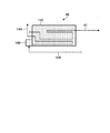
- FIG. 2 is a schematic configuration diagram showing the heating means and the exhaust fuel gas discharge line in the power generation system according to one embodiment of the present invention.
- FIG. 3 is a schematic configuration diagram illustrating a bus heater of the fuel gas heating unit.
- FIG. 4 is a flowchart illustrating an example of the driving operation of the power generation system according to the present embodiment.
- FIG. 5 is a time chart showing the timing of the operation of the valve that controls the flow of the exhaust fuel gas in the power generation system of this embodiment.
- FIG. 6 is a flowchart illustrating an example of the driving operation of the power generation system according to the present embodiment.
- the power generation system of this embodiment is a triple combined cycle (registered trademark) in which a solid oxide fuel cell (hereinafter referred to as SOFC), a gas turbine, and a steam turbine are combined.
- SOFC solid oxide fuel cell
- gas turbine gas turbine
- steam turbine steam turbine
- This triple combined cycle realizes extremely high power generation efficiency because it can generate power in three stages: SOFC, gas turbine, and steam turbine by installing SOFC upstream of gas turbine combined cycle power generation (GTCC). be able to.
- GTCC gas turbine combined cycle power generation
- a solid oxide fuel cell is applied as the fuel cell of the present invention, but the present invention is not limited to this type of fuel cell.
- FIG. 1 is a schematic configuration diagram showing a power generation system of the present embodiment.
- the power generation system 10 includes a gas turbine 11 and a generator 12, an SOFC 13, a steam turbine 14 and a generator 15.
- the power generation system 10 is configured to obtain high power generation efficiency by combining power generation by the gas turbine 11, power generation by the SOFC 13, and power generation by the steam turbine 14.
- the power generation system 10 includes a control device 62.
- the control device 62 controls the operation of each unit of the power generation system 10 based on the input setting, the input instruction, the result detected by the detection unit, and the like.
- the gas turbine 11 includes a compressor 21, a combustor 22, and a turbine 23, and the compressor 21 and the turbine 23 are coupled to each other by a rotary shaft 24 so as to be integrally rotatable.
- the compressor 21 compresses the air A taken in from the air intake line 25.
- the combustor 22 mixes and combusts the compressed air A ⁇ b> 1 supplied from the compressor 21 through the first compressed air supply line 26 and the fuel gas L ⁇ b> 1 supplied from the first fuel gas supply line 27.
- the turbine 23 is rotated by the combustion gas G ⁇ b> 1 supplied from the combustor 22 through the exhaust gas supply line 28.
- the turbine 23 is supplied with compressed air A1 compressed by the compressor 21 through the passenger compartment, and cools the blades and the like using the compressed air A1 as cooling air.
- the generator 12 is provided on the same axis as the turbine 23 and can generate electric power when the turbine 23 rotates.
- liquefied natural gas LNG is used as the fuel gas L1 supplied to the combustor 22.
- the SOFC 13 generates power by reacting at a predetermined operating temperature by being supplied with high-temperature fuel gas as a reducing agent and high-temperature air (oxidizing gas) as an oxidant.
- the SOFC 13 is configured by accommodating an air electrode, a solid electrolyte, and a fuel electrode in a pressure vessel. A part of the compressed air A2 compressed by the compressor 21 is supplied to the air electrode, and the fuel gas L2 is supplied to the fuel electrode to generate power.
- the fuel gas L2 supplied to the SOFC 13 for example, liquefied natural gas (LNG), hydrogen (H 2 ), carbon monoxide (CO), hydrocarbon gas such as methane (CH 4 ), carbon such as coal, etc. Gas produced by gasification equipment for quality raw materials is used.
- the oxidizing gas supplied to the SOFC 13 is a gas containing approximately 15% to 30% oxygen, and typically air is preferable. However, in addition to air, a mixed gas of combustion exhaust gas and air, oxygen And the like can be used (hereinafter, the oxidizing gas supplied to the SOFC 13 is referred to as air).
- the SOFC 13 is connected to the second compressed air supply line 31 branched from the first compressed air supply line 26, and can supply a part of the compressed air A2 compressed by the compressor 21 to the introduction portion of the air electrode.
- the second compressed air supply line 31 is provided with a control valve 32 capable of adjusting the amount of air to be supplied and a blower (a booster) 33 capable of increasing the pressure of the compressed air A2 along the flow direction of the compressed air A2. Yes.
- the control valve 32 is provided on the upstream side in the flow direction of the compressed air A ⁇ b> 2 in the second compressed air supply line 31, and the blower 33 is provided on the downstream side of the control valve 32.
- the SOFC 13 is connected to an exhaust air line 34 that exhausts compressed air A3 (exhaust air) used at the air electrode.
- the exhaust air line 34 is branched into a discharge line 35 that discharges compressed air A3 used in the air electrode to the outside, and a compressed air circulation line 36 that is connected to the combustor 22.
- the discharge line 35 is provided with a control valve 37 capable of adjusting the amount of air discharged
- the compressed air circulation line 36 is provided with a control valve 38 capable of adjusting the amount of air circulated.
- the SOFC 13 is provided with a second fuel gas supply line 41 for supplying the fuel gas L2 to the introduction portion of the fuel electrode.
- the second fuel gas supply line 41 is provided with a control valve 42 that can adjust the amount of fuel gas to be supplied.
- the SOFC 13 is connected to an exhaust fuel line 43 that exhausts the exhaust fuel gas L3 used at the fuel electrode.
- the exhaust fuel line 43 is branched into an exhaust line 44 that discharges to the outside and an exhaust fuel gas supply line 45 that is connected to the combustor 22.
- the discharge line 44 is provided with a control valve 46 capable of adjusting the amount of fuel gas to be discharged, and the exhaust fuel gas supply line 45 is capable of boosting the exhaust fuel gas L3 and a control valve 47 capable of adjusting the amount of fuel gas to be supplied.
- a blower 48 is provided along the flow direction of the exhaust fuel gas L3.
- the control valve 47 is provided on the upstream side in the flow direction of the exhaust fuel gas L 3 in the exhaust fuel gas supply line 45, and the blower 48 is provided on the downstream side of the control valve 47.
- the SOFC 13 is provided with a fuel gas recirculation line 49 that connects the exhaust fuel line 43 and the second fuel gas supply line 41.
- the fuel gas recirculation line 49 is provided with a recirculation blower 50 that recirculates the exhaust fuel gas L3 of the exhaust fuel line 43 to the second fuel gas supply line 41.
- the steam turbine 14 is configured such that the turbine 52 is rotated by steam generated by the exhaust heat recovery boiler (HRSG) 51.
- the exhaust heat recovery boiler 51 is connected to an exhaust gas line 53 from the gas turbine 11 (the turbine 23), and generates steam S by exchanging heat between the air and the high temperature exhaust gas G2.
- the steam turbine 14 (turbine 52) is provided with a steam supply line 54 and a water supply line 55 between the exhaust heat recovery boiler 51.
- the water supply line 55 is provided with a condenser 56 and a water supply pump 57.
- the generator 15 is provided coaxially with the turbine 52 and can generate electric power when the turbine 52 rotates.
- the exhaust gas G2 from which heat has been recovered by the exhaust heat recovery boiler 51 is released to the atmosphere after removing harmful substances.
- the operation of the power generation system 10 of the present embodiment will be described.
- the electric power generation system 10 starts in order of the gas turbine 11, the steam turbine 14, and SOFC13.
- the compressor 21 compresses the air A
- the combustor 22 mixes and combusts the compressed air A1 and the fuel gas L1
- the turbine 23 rotates by the combustion gas G1, thereby generating power.
- the machine 12 starts power generation.
- the turbine 52 is rotated by the steam S generated by the exhaust heat recovery boiler 51, whereby the generator 15 starts power generation.
- the compressed air A2 is supplied from the compressor 21 to start pressurization of the SOFC 13 and to start heating.
- the control valve 37 of the discharge line 35 and the control valve 38 of the compressed air circulation line 36 closed and the blower 33 of the second compressed air supply line 31 stopped the control valve 32 is opened by a predetermined opening.
- a part of the compressed air A2 compressed by the compressor 21 is supplied from the second compressed air supply line 31 to the SOFC 13 side.
- the pressure on the SOFC 13 side increases as the compressed air A2 is supplied.
- the fuel gas L2 is supplied and pressurization is started.
- the control valve 46 of the exhaust line 44 and the control valve 47 of the exhaust fuel gas supply line 45 closed and the blower 48 stopped, the control valve 42 of the second fuel gas supply line 41 is opened and the fuel gas is recirculated.
- the recirculation blower 50 of the line 49 is driven.
- the fuel gas L2 is supplied from the second fuel gas supply line 41 to the SOFC 13 side, and the exhaust fuel gas L3 is recirculated by the fuel gas recirculation line 49.
- the pressure on the fuel electrode side of the SOFC 13 is increased by supplying the fuel gas L2.
- the control valve 32 When the pressure on the air electrode side of the SOFC 13 becomes the outlet pressure of the compressor 21, the control valve 32 is fully opened and the blower 33 is driven. At the same time, the control valve 37 is opened and the exhaust air A3 from the SOFC 13 is exhausted from the exhaust line 35. Then, the compressed air A2 is supplied to the SOFC 13 side by the blower 33. At the same time, the control valve 46 is opened, and the exhaust fuel gas L3 from the SOFC 13 is discharged from the discharge line 44. When the pressure on the air electrode side and the pressure on the fuel electrode side in the SOFC 13 reach the target pressure, pressurization of the SOFC 13 is completed.
- the control valve 37 is closed and the control valve 38 is opened.
- compressed air A3 from the SOFC 13 is supplied from the compressed air circulation line 36 to the combustor 22.
- the control valve 46 is closed, while the control valve 47 is opened to drive the blower 48.
- the exhaust fuel gas L3 from the SOFC 13 is supplied from the exhaust fuel gas supply line 45 to the combustor 22.
- the fuel gas L1 supplied from the first fuel gas supply line 27 to the combustor 22 is reduced.
- the power generation by the generator 12 by driving the gas turbine 11, the power generation by the SOFC 13, and the power generation by the generator 15 are all performed by driving the steam turbine 14, and the power generation system 10 becomes a steady operation.
- exhaust fuel gas that is not supplied to the gas turbine 11, that is, not burned by the combustor 22, is discharged from the discharge line 44 by opening the control valve 46.
- Such exhaust fuel gas is, for example, exhaust fuel gas whose state (component) is not stable after starting the SOFC 13 or exhaust fuel gas exhausted from the SOFC 13 exceeding the supply amount to the gas turbine 11. And since it is discharged
- heating means 70 that burns exhaust fuel gas that is not supplied to the gas turbine 11 and heats each part of the power generation system 10.
- the heating means 70 includes an exhaust fuel gas discharge line 72, a control valve 73, an exhaust gas heating unit 74, a steam generation unit 76, an air heating unit 78, and a fuel gas heating unit 80.
- the power generation system 10 is provided with heating means 70 that heats at least one of exhaust gas, steam, fuel gas, and air flowing through the power generation system 10 by burning the exhaust fuel gas L3 that is not supplied to the gas turbine 11.
- the power generation system 10 can effectively use the combustion calorific value (calories) contained in the exhaust fuel gas L3 discharged from the discharge line 44, and efficiently use the exhaust fuel gas discharged from the SOFC 13. can do.
- One end of the exhaust fuel gas discharge line 72 is connected between the blower 48 of the exhaust fuel gas supply line 45 and the combustor 22.
- the other end of the exhaust fuel gas discharge line 72 is branched into a plurality of parts.
- the first branch line 102 of the exhaust gas heating unit 74, the second branch line 104 of the steam generation unit 76, and the air heating unit 78, respectively. are connected to the third branch line 106 and the fourth branch line 108 of the fuel gas heating unit 80.
- the exhaust fuel gas discharge line 72 supplies the exhaust fuel gas L3 supplied from the exhaust fuel gas supply line 45 to the branched lines.
- the control valve 73 is installed in the exhaust fuel gas discharge line 72.
- the control valve 73 switches the flow of the exhaust fuel gas L3 in the exhaust fuel gas discharge line 72 by switching between opening and closing, and the flow rate of the exhaust fuel gas L3 flowing through the exhaust fuel gas discharge line 72 by adjusting the opening degree. Control.
- the exhaust gas heating unit 74 includes a duct burner 90, a first branch line 102, a first control valve 112, a third fuel gas supply line 122, and a control valve 132.
- the duct burner 90 is disposed in the exhaust heat recovery boiler 51.
- the duct burner 90 heats the exhaust gas G2 in the exhaust heat recovery boiler 51 by burning the supplied fuel.
- the duct burner 90 may be provided in the exhaust gas line 53 on the upstream side of the exhaust heat recovery boiler 51.
- the first branch line 102 has one end connected to the exhaust fuel gas discharge line 72 and the other end connected to the duct burner 90.
- the first control valve 112 is installed in the first branch line 102.
- the first control valve 112 switches the flow of the exhaust fuel gas L3 in the first branch line 102 by switching between opening and closing, and controls the flow rate of the exhaust fuel gas L3 flowing in the first branch line 102 by adjusting the opening degree.
- the third fuel gas supply line 122 is connected to the duct burner 90 and supplies the fuel gas L4 to the duct burner 90.
- the control valve 132 is installed in the third fuel gas supply line 122 and adjusts the amount of the fuel gas L4 supplied to the duct burner 90 by adjusting at least one of opening / closing and opening.
- the exhaust gas heating unit 74 heats the exhaust gas G2 by burning the exhaust fuel gas L3 supplied from the first branch line 102 and the fuel gas L4 supplied from the third fuel gas supply line 122 in the duct burner 90. Thereby, the temperature of the exhaust gas G2 in the exhaust heat recovery boiler 51 can be increased, and more heat can be recovered by the exhaust heat recovery boiler 51. Further, the exhaust gas heating unit 74 can heat the exhaust gas G2 with calories contained in the exhaust fuel gas L3 by burning the exhaust fuel gas L3 supplied from the first branch line 102. Thereby, the calories contained in the exhaust fuel gas L3 can be utilized effectively.
- the steam generation unit 76 includes a boiler 92, a second branch line 104, a second control valve 114, a fourth fuel gas supply line 124, an air supply line 125, and control valves 134 and 135. .
- the boiler 92 is a steam generator that generates steam using heat generated by burning supplied fuel, and supplies the generated steam to the fuel gas recirculation line 49.
- the boiler 92 of this embodiment has a function of a so-called startup boiler that is used to start the SOFC 13.
- the boiler 92 may be connected to other devices of the power generation system 10 and supply steam to the connected devices.
- the second branch line 104 has one end connected to the exhaust fuel gas discharge line 72 and the other end connected to the boiler 92.
- the second control valve 114 is installed in the second branch line 104.
- the second control valve 114 controls the flow rate of the exhaust fuel gas L3 flowing through the second branch line 104 by switching the opening and closing to switch the flow of the exhaust fuel gas L3 in the second branch line 104 and adjusting the opening degree.
- the fourth fuel gas supply line 124 is connected to the boiler 92 and supplies the fuel gas L ⁇ b> 5 to the boiler 92.
- the air supply line 125 is connected to the boiler 92 and supplies air A4 to the boiler 92.
- the control valve 134 is installed in the fourth fuel gas supply line 124, and adjusts the amount of the fuel gas L5 supplied to the boiler 92 by adjusting at least one of opening / closing and opening.
- the control valve 135 is installed in the air supply line 125, and adjusts the amount of air A4 supplied to the boiler 92 by adjusting at least one of opening / closing and opening.
- the steam generation unit 76 supplies the exhaust fuel gas L3 supplied from the second branch line 104 and the fuel gas L5 supplied from the fourth fuel gas supply line 124 to the boiler 92 together with the air A4 supplied from the air supply line 125.
- steam is generated.
- the steam required in the power generation system 10 can be generated by the boiler 92 and supplied to each part.
- the steam generation part 76 can make the calorie contained in the exhaust fuel gas L3 into the heat
- FIG. Thereby, the calories contained in the exhaust fuel gas L3 can be utilized effectively.
- the air heating unit 78 includes an air temperature raising burner 94, a third branch line 106, a third control valve 116, a fifth fuel gas supply line 128, and a control valve 138.
- the air temperature raising burner 94 is disposed in the second compressed air supply line 31.
- the air temperature raising burner 94 heats the compressed air A2 in the second compressed air supply line 31 by burning the supplied fuel.
- the air heating unit 78 is a so-called burner provided with an ignition source for igniting and fueling the exhaust fuel gas L3 as an air temperature raising burner 94 for combusting the exhaust fuel gas L3, or a reaction such as oxidation of the exhaust fuel gas L3.
- a combustion catalyst for burning can be used.
- the air heating unit 78 preferably connects the outlet of the recirculation blower 50 or the outlet of the blower 48 to the third branch line 106. As a result, higher pressure exhaust fuel gas L3 can be provided to the air temperature raising burner 94.
- the third branch line 106 has one end connected to the exhaust fuel gas discharge line 72 and the other end connected to the air temperature raising burner 94.
- the third control valve 116 is installed in the third branch line 106.
- the third control valve 116 switches the flow of the exhaust fuel gas L3 in the third branch line 106 by switching between opening and closing, and controls the flow rate of the exhaust fuel gas L3 flowing through the third branch line 106 by adjusting the opening degree.
- the fifth fuel gas supply line 128 is connected to the air temperature raising burner 94 and supplies the fuel gas L 6 to the air temperature raising burner 94.
- the control valve 138 is installed in the fifth fuel gas supply line 128 and adjusts the amount of the fuel gas L6 supplied to the air temperature raising burner 94 by adjusting at least one of opening / closing and opening.
- the air heating unit 78 burns the exhaust fuel gas L3 supplied from the third branch line 106 and the fuel gas L6 supplied from the fifth fuel gas supply line 128 by the air temperature raising burner 94, so that the compressed air A2 Heat. Thereby, the temperature of compressed air A2 supplied to SOFC13 can be made higher.
- the compressed air A2 supplied to the SOFC 13 is supplied to the gas turbine 11 as exhaust air. Thereby, the heat which heated compressed air A2 with the air heating part 78 is recoverable with the gas turbine 11 or the exhaust heat recovery boiler 51. FIG. Thereby, the calories contained in the exhaust fuel gas L3 can be utilized effectively.
- the fuel gas heating unit 80 includes a bath heater 96, a fourth branch line 108, a fourth control valve 118, a second fuel gas supply line 41, and a control valve 42.
- the bus heater 96 is disposed in the second fuel gas supply line 41.
- the bus heater 96 heats the fuel gas L2 in the second fuel gas supply line 41 by burning the supplied exhaust fuel gas.
- FIG. 3 is a schematic configuration diagram showing the bus heater of the fuel gas heating unit.
- the bath heater 96 includes a combustor 140, a container 142, and a combustion gas pipe 144.
- the combustor 140 is connected to the fourth branch line 108 and the combustion gas pipe 144.
- the combustor 140 supplies the combustion gas generated by burning the exhaust fuel gas L3 supplied from the fourth branch line 108 to the combustion gas pipe 144.
- the container 142 is a box filled with a heat medium such as water.
- the second fuel gas supply line 41 and the combustion gas pipe 144 are arranged inside the heat medium.
- the combustion gas pipe 144 has one end connected to the combustor 140 and the other end open. A portion between both ends of the combustion gas pipe 144 is disposed inside the container 142.
- the bus heater 96 In the bus heater 96, the exhaust fuel gas is combusted in the combustor 140, and the generated combustion gas flows through the combustion gas pipe 144. As a result, the combustion gas flows inside the container 142. In the bus heater 96, the heat medium is heated by the combustion gas flowing through the combustion gas pipe 144, and the heated heat medium heats the fuel gas flowing through the second fuel gas supply line 41. Thus, the bus heater 96 heats the fuel gas by transferring the heat of the combustion gas to the fuel gas via the heat medium. The bus heater 96 can be heated while preventing the fuel gas from being burned in the second fuel gas supply line 41 by heating the fuel gas via the heat medium.
- the fourth branch line 108 has one end connected to the exhaust fuel gas discharge line 72 and the other end connected to the bus heater 96.
- the fourth control valve 118 is installed in the fourth branch line 108.
- the fourth control valve 118 switches the flow of the exhaust fuel gas L3 in the fourth branch line 108 by switching between opening and closing, and controls the flow rate of the exhaust fuel gas L3 flowing through the fourth branch line 108 by adjusting the opening degree. To do.
- the fuel gas heating unit 80 heats the fuel gas L ⁇ b> 2 by burning the exhaust fuel gas L ⁇ b> 3 supplied from the fourth branch line 108 with the bath heater 96. Thereby, the temperature of the fuel gas L2 supplied to the SOFC 13 can be further increased.
- the fuel gas L2 supplied to the SOFC 13 is supplied to the gas turbine 11 as exhaust fuel gas. Thereby, the heat which heated the fuel gas in the fuel gas heating part 80 can be collect
- the fuel gas heating unit 80 may be provided with a path for supplying fuel gas to the bus heater 96 separately from the path for supplying exhaust fuel gas.
- the power generation system 10 includes an open / close valve (open / close control valve) 64 disposed in the vicinity of the gas turbine 11 of the exhaust fuel gas supply line 45 (in the present embodiment, downstream of the control valve 47), and an exhaust fuel line.
- 43 is provided with a flow rate detection unit 66 for detecting the flow rate of the exhaust fuel gas L3 flowing through the exhaust gas 43, and a state detection unit 68 for detecting the state of the exhaust fuel gas L3 flowing through the exhaust fuel gas supply line 45.
- the on-off valve 64 is disposed downstream of the position connected to the exhaust fuel gas discharge line 72 and upstream of the combustor 22.
- the on-off valve 64 can switch whether to supply the exhaust fuel gas L3 to the combustor 22 by switching between opening and closing.
- the flow rate detection unit 66 is downstream of a portion connected to the fuel gas recirculation line 49 of the exhaust fuel line 43 and upstream of a portion branched to the exhaust line 44 and the exhaust fuel gas supply line 45. Is arranged.
- the flow rate detection unit 66 is a detection device that detects the flow rate of the exhaust fuel gas L3 flowing through the exhaust fuel line 43 at the installed position.
- the flow rate detector 66 detects the pressure of the exhaust fuel gas L3 flowing through the exhaust fuel line 43, for example, and calculates the flow rate by performing arithmetic processing on the pressure detection result.
- the flow rate of the exhaust fuel gas L3 flowing through the exhaust fuel line 43 is also included in the state of the exhaust fuel gas.
- the state detection unit 68 is disposed downstream of the blower 48 of the exhaust fuel gas supply line 45 and upstream of the position connected to the exhaust fuel gas discharge line 72.
- the state detection unit 68 is a detection device that detects the calories of the exhaust fuel gas L3 flowing through the exhaust fuel gas supply line 45 at the installed position.
- the state detection unit 68 may be any detection device that can detect the state of the exhaust fuel gas L3 flowing through the exhaust fuel gas supply line 45 at the installed position.
- the state detection unit 68 is a temperature that detects the temperature of the exhaust fuel gas L3.
- a detection device can also be used.
- the state of the exhaust fuel gas L3 is various conditions that can determine whether drain has occurred in the exhaust fuel gas L3 while flowing through the exhaust fuel gas supply line 45.
- the state detection unit 68 is preferably arranged on the combustor 22 side of the exhaust fuel gas supply line 45, that is, on the side close to the position connected to the exhaust fuel gas discharge line 72. Thereby, when the exhaust fuel gas supply line 45 flows, the change produced in the exhaust fuel gas L3 can be detected with higher probability.
- the control device (control unit) 62 of the power generation system 10 includes the flow rate detection unit 66 and the state detection unit 68 at the start of supply of the exhaust fuel gas L3 from the SOFC 13 to the exhaust fuel line 43, that is, after the control valve 47 is opened.
- the heating means 70 is driven based on at least one result.
- the control device 62 also controls opening / closing of the on-off valve 64 based on at least one result of the flow rate detection unit 66 and the state detection unit 68. Thereby, it is possible to switch whether or not the exhaust fuel gas is supplied to the combustor 22.
- FIG. 4 is a flowchart illustrating an example of the driving operation of the power generation system according to the present embodiment.
- FIG. 5 is a time chart showing the timing of the operation of the valve that controls the flow of the exhaust fuel gas in the power generation system of this embodiment.
- the driving operation shown in FIG. 4 can be realized by the control device (control unit) 62 executing arithmetic processing based on the detection result of each unit. Further, the power generation system 10 executes the exhaust fuel gas circulation in parallel using the fuel gas recirculation line 49 even during the execution of the processing shown in FIG.
- FIG. 4 is an example of the control executed when the SOFC 13 is activated.
- the control device 62 controls the control valve 47 of the exhaust fuel gas supply line 45, the control valve 73 of the exhaust fuel gas discharge line 72, and the exhaust fuel gas supply line as shown in FIG. 45 open / close valves 64 are closed.
- the power generation system 10 of the present embodiment basically keeps the control valve 46 closed, and does not discharge the exhaust fuel gas from the discharge line 44.
- the control device 62 performs control to switch the control valve 47 of the exhaust fuel gas supply line 45 from closed to open (step S12). For example, when the exhaust gas L3 is circulated in the fuel gas recirculation line 49, the control valve 47 is switched from closed to open by the control device 62, whereby the exhaust fuel gas L3 to the exhaust fuel gas supply line 45 is changed. Start supplying.
- the control device 62 can determine the flow rate of the exhaust fuel gas L3 in the path using the detection result of the flow rate detector 66.
- the control device 62 performs control to open the control valve 47 of the exhaust fuel gas supply line 45 and open the control valve 73 of the exhaust fuel gas discharge line 72 as indicated by t1 in FIG. . Further, the control device 62 keeps the open / close valve 64 of the exhaust fuel gas supply line 45 closed. As a result, the exhaust fuel gas L3 is supplied to the heating means 70.
- control device 62 When the control device 62 starts supplying the exhaust fuel gas L3 to the exhaust fuel gas supply line 45, the control device 62 controls to drive the blower 48 of the exhaust fuel gas supply line 45 (step S14).
- the blower 48 sends the exhaust fuel gas L ⁇ b> 3 flowing through the exhaust fuel gas supply line 45 toward the connecting portion with the exhaust fuel gas discharge line 72.
- the control device 62 determines the supply destination of the exhaust fuel gas L3 (step S16). Specifically, the control device 62 determines the supply destination of the exhaust fuel gas from the exhaust gas heating unit 74, the steam generation unit 76, the air heating unit 78, and the fuel gas heating unit 80 of the heating unit 70. After determining the supply destination, the control device 62 performs control to switch the control valve of the supply destination line (branch line) from closed to open (step S18). Thereby, the exhaust fuel gas L3 can be supplied to the determined supply destination of the heating means 70.
- the control device 62 detects the state of the exhaust fuel gas L3 by the state detection unit 68 (step S20), and determines whether the state of the exhaust fuel gas L3 is stable (step S22). That is, the control device 62 determines whether the component of the exhaust fuel gas L3 flowing through the exhaust fuel gas supply line 45 is stable. For example, when the state detection unit 68 detects the calorie of the exhaust fuel gas L3, the control device 62 determines that the state is stable when the calorie falls within a predetermined range. Further, the state detection unit 68 can also measure the temperature of the exhaust fuel gas L3 as the state of the exhaust fuel gas L3. When the temperature is detected by the state detection unit 68, it is determined that the state is stable when the temperature reaches a certain value or more.
- Step S22 When it is determined that the state of the exhaust fuel gas L3 is not stable (No in Step S22), the control device 62 returns to Step S16 and performs the process of Step S16 again.
- the control device 62 repeats the processing from step S16 to step S22 while supplying the exhaust fuel gas L3 to the heating means 70 until the state of the exhaust fuel gas L3 flowing through the exhaust fuel line 43 is stabilized.
- Step S24 the control device 62 performs control to switch the open / close valve 64 of the exhaust fuel gas supply line 45 from closed to open.
- the control device 62 switches the control valve 73 of the exhaust fuel gas discharge line 72 from open to closed while maintaining the control valve 47 of the exhaust fuel gas supply line 45 open.
- the on-off valve 64 of the exhaust fuel gas supply line 45 is controlled to be switched from closed to open.
- the control device 62 stops the supply of the exhaust fuel gas L3 to the exhaust fuel gas discharge line 72 and starts the supply of the exhaust fuel gas L3 to the combustor 22.
- the control device 62 ends this processing.
- the power generation system 10 of the present embodiment is provided with the heating means 70, and when the SOFC 13 is started up or the like, the state of the exhaust fuel gas L3 is stabilized, that is, the exhaust fuel gas L3 can be supplied to the combustor 22. In the meantime, the exhaust fuel gas L3 discharged from the SOFC 13 is supplied to the heating means 70. Thereby, the exhaust fuel gas that cannot be supplied to the combustor 22 can be used as fuel for the heating means 70 without being discharged from the discharge line 44. Further, since the heating means 70 is heating exhaust gas, steam, air, or fuel used in the power generation system 10, the energy that has heated the heating target can be recovered by the gas turbine 11 or the steam turbine 14.
- the power generation system 10 places the exhaust fuel gas discharge line 72 of the heating means 70 between the blower 48 of the exhaust fuel gas supply line 45 and the on-off valve 64, that is, to the combustor 22 side of the exhaust fuel gas supply line 45. Connected. Thus, in the power generation system 10, the exhaust fuel gas L ⁇ b> 3 that has reached the vicinity of the combustor 22 in the exhaust fuel gas supply line 45 is supplied to the heating unit 70. Thus, the power generation system 10 can heat the exhaust fuel gas supply line 45 with the exhaust fuel gas until the state of the exhaust fuel gas L3 is stabilized.
- the power generation system 10 supplies the exhaust fuel gas L3 to the heating means 70 until the exhaust fuel gas L3 reaching the vicinity of the combustor 22 of the exhaust fuel gas supply line 45 is stabilized. Accordingly, when the SOFC 13 is started, the exhaust fuel gas L3 flows through the exhaust fuel gas supply line 45 in a low temperature (normal temperature) state, and the supply of the exhaust fuel gas L3 having a lowered temperature to the combustor 22 is suppressed. be able to.
- the exhaust fuel gas L3 when the exhaust fuel gas L3 is cooled, drainage is generated.
- the composition of the components changes, and the amount of moisture decreases, so that the combustion calorific value (calories) increases.
- the amount of drain generated gradually changes. Thereafter, when the drain generated in the exhaust fuel gas supply line 45 evaporates, the evaporated drain enters the exhaust fuel gas L3, and the H 2 O content of the exhaust fuel gas L3 increases.
- the exhausted fuel gas L3 has a lower calorific value as the amount of H 2 O increases.
- the fuel heat generation amount of the exhaust fuel gas L3 on the downstream side of the exhaust fuel gas supply line 45 gradually changes.
- the combustion control in the combustor 22 becomes complicated. Further, it is not preferable to supply the exhaust fuel gas L3 in a state where drain is generated to the combustor 22 in the first place.
- the power generation system 10 according to the present embodiment starts supplying the exhaust fuel gas L3 to the combustor 22 after the state of the exhaust fuel gas L3 is stabilized when the SOFC 13 is started. Thereby, the fluctuation
- the combustion of the combustor 22 can be stabilized by stabilizing the component of the supplied exhaust fuel gas L3. As a result, control can be simplified, and adverse effects on the gas turbine 11 can be reduced.
- the power generation system 10 connects the exhaust fuel gas discharge line 72 to the downstream side of the blower 48 of the exhaust fuel gas supply line 45, thereby serving as a drive source for supplying the exhaust fuel gas L3 to the exhaust fuel gas discharge line 72.
- Blower 48 can be used. Thereby, one blower 48 can be used effectively.
- the on-off valve 64 in the vicinity of the combustor 22 of the exhaust fuel gas supply line 45. That is, the power generation system 10 preferably shortens the distance between the on-off valve 64 and the combustor 22.
- the power generation system 10 preferably shortens the distance between the on-off valve 64 and the combustor 22.
- the on-off valve 64 is opened and the supply of the exhaust fuel gas L3 to the combustor 22 is started, the range of the exhaust fuel gas supply line 45 heated by the exhaust fuel gas L3 supplied to the combustor 22 is shortened. be able to.
- the generation of drain in the exhaust fuel gas L3 of the exhaust fuel gas supply line 45 in the range downstream of the on-off valve 64 is suppressed. Can do.
- FIG. 6 is a flowchart illustrating an example of the driving operation of the power generation system according to the present embodiment.
- the driving operation shown in FIG. 6 can be realized by the control device (control unit) 62 executing arithmetic processing based on the detection results of the respective units.
- FIG. 6 is an example of control executed in a state where the exhaust fuel gas is supplied to the gas turbine.
- FIG. 6 illustrates processing when each control valve is opened, but control for opening to closing and control for adjusting the opening degree can also be realized by similar processing.
- the control in FIG. 6 can also be executed as the control in steps S16 and S18 in FIG.
- the control device 62 detects the flow rate of the exhaust fuel gas L3 by the flow rate detection unit 66 (step S30), and determines whether the exhaust fuel gas is supplied to the heating means 70 (step S32). For example, when the flow rate detected by the flow rate detection unit 66 exceeds the flow rate of the exhaust fuel gas L3 required for the combustor 22 due to fluctuations in the operating state of the gas turbine 11, the control device 62 supplies the excess exhaust fuel gas L3. It determines with supplying to the heating means 70. FIG. When the control device 62 determines not to supply the exhaust fuel gas L3 to the heating means 70 (No in step S32), that is, to supply the entire amount of exhaust fuel gas L3 to the combustor 22, the control device 62 returns to step S30. Thereby, the control device 62 repeats the processes of step S30 and step S32 until it determines that the exhaust fuel gas L3 is supplied to the heating means 70.
- the control device 62 supplies the exhaust fuel gas L3 to the heating means 70 (Yes in step S32), that is, if it is determined that the entire amount of exhaust fuel gas L3 cannot be supplied to the combustor 22, the control of the exhaust fuel gas discharge line 72 is performed.
- the valve 73 is switched from closed to open (step S34), and it is determined whether the exhaust fuel gas L3 is supplied to the duct burner 90 (step S36).
- the control device 62 performs control to open the first control valve 112 from the closed state (Step S38).
- Step S40 determines whether to supply the exhaust fuel gas L3 to the boiler 92. Further, the control device 62 determines whether to supply the exhaust fuel gas L3 to the boiler 92 even when the first control valve 112 is opened from the closed state (step S40). When it is determined that the exhaust fuel gas L3 is supplied to the boiler 92 (Yes in Step S40), the control device 62 performs control to open the second control valve 114 from the closed state (Step S42).
- the control device 62 determines whether to supply the exhaust fuel gas L3 to the air temperature raising burner 94 (step S44). Further, the control device 62 determines whether or not to supply the exhaust fuel gas L3 to the air temperature raising burner 94 even when the second control valve 114 is opened from the closed state (step S44). When it is determined that the exhaust fuel gas L3 is supplied to the air temperature raising burner 94 (Yes in Step S44), the control device 62 performs control to open the third control valve 116 from the closed state (Step S46).
- the control device 62 determines whether the exhaust fuel gas L3 is supplied to the bus heater 96 (Step S48). Further, the control device 62 determines whether the exhaust fuel gas L3 is supplied to the bus heater 96 even when the third control valve 116 is opened from the closed state (step S48). When it is determined that the exhaust fuel gas L3 is supplied to the bus heater 96 (Yes in step S48), the control device 62 performs control to open the fourth control valve 118 from the closed state (step S50).
- Step S52 determines whether or not the process is finished. Further, the control device 62 determines whether or not the process is finished when the fourth control valve 118 is opened from the closed state (step S52). If it is determined that the process is not finished (No in step S52), the control device 62 returns to step S30 and executes the above process again. When it is determined that the process is to be ended (Yes in step S52), the control device 62 ends this process.
- the control device 62 performs the process shown in FIG. 6, so that even if the exhaust fuel gas L3 not supplied to the combustor 22 is generated after the supply of the exhaust fuel gas L3 to the gas turbine 11 is started, this exhaust fuel The gas L3 can be used effectively. That is, the exhaust fuel gas L3 that is not supplied to the combustor 22 can be used as the fuel for the heating means 70, and the exhaust fuel gas L3 can be used effectively.
- the control device 62 when the SOFC 13 is activated, the control device 62 performs control to supply the exhaust fuel gas L3 to the boiler 92 (steam generation unit 76), and then supplies the exhaust fuel gas L3 to the duct burner 90 (exhaust gas heating unit 74). Can be controlled. Further, when the operating SOFC 13 trips, the control device 62 performs control to supply the exhaust fuel gas L3 to the duct burner 90 (exhaust gas heating unit 74).
- steps S36 and S40 are performed regardless of the result of opening and closing so that the exhaust fuel gas L3 can be supplied to a plurality of the duct burner 90, the boiler 92, the air temperature raising burner 94, and the bus heater 96.
- the control is executed to execute the determinations in step S44 and step S48, the present invention is not limited to this.
- the control device 62 may proceed to the determination of step S52 after performing the processing of step S38, step S42, step S46, and step S50.
- the heating means 70 of this embodiment is provided with four mechanisms, an exhaust gas heating unit 74, a steam generation unit 76, an air heating unit 78, and a fuel gas heating unit 80, as a mechanism for burning the exhaust fuel gas. It suffices to have at least one. Further, the mechanism for burning the exhaust fuel gas included in the heating means 70 is not limited to the above four mechanisms, and any mechanism other than the gas turbine 11 that can be used for the power generation system 10 may be used.
- the heating means 70 of the present embodiment can use each part of the heating means 70 even when the exhaust fuel gas is not supplied by providing a path for supplying the fuel gas in the region where the exhaust fuel gas is combusted. .
- the heating means 70 can use the exhaust fuel gas as auxiliary fuel and can always operate, so that each part of the heating means 70 can be used efficiently.
- the control device 62 controls the control valves 132, 134, and 138 together with the control of the first control valve 112, the second control valve 114, the third control valve 116, and the fourth control valve 118,
- the balance between the exhaust fuel gas L3 supplied to each part of the heating means 70 and the fuel gases L4, L5, and L6 can be adjusted.
- the control device 62 can control the amount of combustion and the amount of heat generated in the duct burner 90 by adjusting the balance between the opening degree of the first control valve 112 and the opening degree of the control valve 132. it can.
- the control apparatus 62 can control the ratio of the steam generation amount in the gas turbine 11 and the power generation output of the generator 15.
- a path for supplying fuel gas separately from a path for supplying exhaust fuel gas to each part of the heating means 70 as in this embodiment. Is preferably provided, but not necessarily provided.
- the power generation system 10 of the present embodiment is provided with the control valve 47 upstream of the blower 48 and the state detection unit 68 of the exhaust fuel gas supply line 45, so that the blower 48 and the state of the exhaust fuel gas supply line 45 are provided. It is possible to switch whether or not to supply the exhaust fuel gas L3 to the range where the detection unit 68 is disposed.
- the position of the control valve 47 is the position where the control valve 47 is disposed on the combustor 22 side of the exhaust fuel gas supply line 45, but the position of the control valve 47 is not particularly limited, and is downstream of the connecting portion with the exhaust line 44. And it should just be an upstream rather than the connection part with the exhaust fuel gas discharge line 72.
- the power generation system 10 of the present embodiment can heat the exhaust fuel gas supply line 45, it is preferable to connect the exhaust fuel gas discharge line 72 of the heating means 70 to the gas turbine 11 side of the exhaust fuel gas supply line 45.
- the present invention is not limited to this.
- the exhaust fuel gas discharge line 72 may be connected to the exhaust fuel line 43 or the exhaust line 44.
- the power generation system 10 of the present embodiment can discharge the exhaust fuel gas to the exhaust fuel gas discharge line 72 instead of discharging the exhaust fuel gas from the discharge line 44, and therefore the discharge line 44 and the control valve 46 need not be provided. . That is, the power generation system 10 may be provided with the exhaust fuel gas discharge line 72 instead of the discharge line 44.
- the power generation system 10 of the present embodiment may be provided with a drain recovery mechanism for recovering drain from the exhaust fuel gas L3 in the exhaust fuel gas discharge line 72.
- a drain recovery mechanism for example, a mechanism for cooling the exhaust fuel gas L3 and a mechanism (trap) for collecting the drain are provided.
- the drain recovery mechanism uses a reheat exchanger, cools the exhaust fuel gas L3 by heat exchange, recovers the drain, and then recovers the heat from the exhaust fuel gas L3 before recovering the drain. You may make it reheat.
- the power generation system 10 of the present embodiment is provided with the control valve 73 and switches whether or not to supply the exhaust fuel gas to the exhaust fuel gas discharge line 72, but the first control valve 112, the second control valve 114, Since the third control valve 116 and the fourth control valve 118 can switch whether or not to supply the exhaust fuel gas to each, the control valve 73 is not necessarily provided.
- the on-off valve 64 that adjusts the supply of fuel gas to the combustor 22 only needs to be able to switch between opening and closing, but may be a control valve that adjusts the opening.
- the control valve 47 disposed on the upstream side of the blower 48 of the exhaust fuel gas supply line 45 only needs to be able to be switched at least, and may be an on-off valve.
- at least one of the control valve 47 and the on-off valve 64 provided in the exhaust fuel gas supply line 45 is preferably a control valve whose opening degree (flow path resistance) can be adjusted. Thereby, the quantity of the exhaust fuel gas supplied to the combustor 22 can be adjusted. Since the power generation system 10 can control the supply of the exhaust fuel gas to the exhaust fuel gas supply line 45 by controlling the opening and closing of the on-off valve 64 and the control valve 73, the control valve 47 need not be provided.
Landscapes
- Engineering & Computer Science (AREA)
- Chemical & Material Sciences (AREA)
- Combustion & Propulsion (AREA)
- Mechanical Engineering (AREA)
- General Engineering & Computer Science (AREA)
- Manufacturing & Machinery (AREA)
- Life Sciences & Earth Sciences (AREA)
- Sustainable Development (AREA)
- Sustainable Energy (AREA)
- Chemical Kinetics & Catalysis (AREA)
- Electrochemistry (AREA)
- General Chemical & Material Sciences (AREA)
- Fuel Cell (AREA)
Abstract
Description
11 ガスタービン
12 発電機
13 固体酸化物形燃料電池(SOFC)
14 蒸気タービン
15 発電機
21 圧縮機
22 燃焼器
23 タービン
25 空気取り込みライン
26 第1圧縮空気供給ライン
27 第1燃料ガス供給ライン
31 第2圧縮空気供給ライン
32 制御弁(第1開閉弁)
33、48 ブロワ
34 排空気ライン
36 圧縮空気循環ライン
41 第2燃料ガス供給ライン
42 制御弁
43 排燃料ライン
44 排出ライン
45 排燃料ガス供給ライン
47 制御弁
49 燃料ガス再循環ライン
50 再循環ブロワ
51 排熱回収ボイラ
52 タービン
53 排ガスライン
54 蒸気供給ライン
55 給水ライン
56 復水器
57 給水ポンプ
62 制御装置(制御部)
64 開閉弁
66 流量検出部
68 状態検出部
70 加熱手段
72 排燃料ガス排出ライン
73 制御弁
74 排ガス加熱部
76 蒸気発生部
78 空気加熱部
80 燃料ガス加熱部
90 ダクトバーナ
92 ボイラ
94 空気昇温用バーナ
96 バスヒータ
102 第1分岐ライン
104 第2分岐ライン
106 第3分岐ライン
108 第4分岐ライン
112 第1制御弁
114 第2制御弁
116 第3制御弁
118 第4制御弁
122 第3燃料ガス供給ライン
124 第4燃料ガス供給ライン
125 空気供給ライン
128 第5燃料ガス供給ライン
132、134、135、138 制御弁
Claims (8)
- 圧縮機と燃焼器を有するガスタービンと、
燃料電池と、
前記燃料電池から排出される排燃料ガスを前記ガスタービンに供給する排燃料ガス供給ラインと、
前記排燃料ガス供給ラインに接続する排燃料ガス排出ラインと、
前記排燃料ガス排出ラインにより供給される前記排燃料ガスを燃焼させて加熱対象を加熱させる加熱手段と、
前記燃料電池から排出される前記排燃料ガスの供給先を制御する制御部と、を有することを特徴とする発電システム。 - 前記ガスタービンから排出される排ガスに含まれる熱を回収する熱交換器をさらに有し、
前記加熱手段は、前記排燃料ガスを燃焼させて前記熱交換器に供給する排ガスを加熱する排ガス加熱部を含むことを特徴とする請求項1に記載の発電システム。 - 前記加熱手段は、前記排燃料ガスを燃焼させて前記燃料電池に供給される燃料ガスに供給する蒸気を発生する蒸気発生部を含むことを特徴とする請求項1または請求項2に記載の発電システム。
- 前記加熱手段は、前記排燃料ガスを燃焼させて前記燃料電池に供給する空気を加熱する空気加熱部を含むことを特徴とする請求項1から請求項3のいずれか一項に記載の発電システム。
- 前記加熱手段は、前記排燃料ガスを燃焼させて前記燃料電池に供給する燃料ガスを加熱する燃料ガス加熱部を含むことを特徴とする請求項1から請求項4のいずれか一項に記載の発電システム。
- 前記排燃料ガス排出ラインよりも上流側の前記排燃料ガスの状態を検出する状態検出部を有し、
前記状態検出部で検出した結果に基づいて、排燃料ガスの状態が安定したと判定した場合、前記ガスタービンへの前記排燃料ガスの供給を開始することを特徴とする請求項1から請求項5のいずれか一項に記載の発電システム。 - 前記燃料電池から前記排燃料ガス供給ライン及び前記排燃料ガス排出ラインに供給される排燃料ガスの流量を検出する流量検出部を有し、
前記制御部は、前記流量検出部の検出結果に基づいて、前記排燃料ガス供給ラインに供給する排燃料ガスの流量と、前記排燃料ガス排出ラインに供給する排燃料ガスの流量と、を制御することを特徴とする請求項1から請求項6のいずれか一項に記載の発電システム。 - 圧縮機と燃焼器を有するガスタービンと、燃料電池と、排燃料ガスを燃焼させて加熱対象を加熱させる加熱手段と、を有する発電システムの運転方法であって、
前記燃料電池からガスタービンに向けて排出される排燃料ガスの状態を検出する工程と、
検出した排燃料ガスの状態に基づいて、前記ガスタービンに供給しない前記排燃料ガスがあるかを判定する工程と、
前記ガスタービンに供給しない排燃料ガスがあると判定した場合、前記加熱手段に前記排燃料ガスを供給する工程と、を有することを特徴とする発電システムの運転方法。
Priority Applications (4)
| Application Number | Priority Date | Filing Date | Title |
|---|---|---|---|
| KR1020157010363A KR101732286B1 (ko) | 2012-11-22 | 2013-11-15 | 발전 시스템 및 발전 시스템의 운전 방법 |
| CN201380054949.3A CN104737346B (zh) | 2012-11-22 | 2013-11-15 | 发电系统以及发电系统的运转方法 |
| US14/435,327 US20150263368A1 (en) | 2012-11-22 | 2013-11-15 | Power generation system and method of operating power generation system |
| DE112013005614.3T DE112013005614T5 (de) | 2012-11-22 | 2013-11-15 | Energieerzeugungssystem und Verfahren zum Betreiben eines Energieerzeugungssystems |
Applications Claiming Priority (2)
| Application Number | Priority Date | Filing Date | Title |
|---|---|---|---|
| JP2012256906A JP6004915B2 (ja) | 2012-11-22 | 2012-11-22 | 発電システム及び発電システムの運転方法 |
| JP2012-256906 | 2012-11-22 |
Publications (1)
| Publication Number | Publication Date |
|---|---|
| WO2014080848A1 true WO2014080848A1 (ja) | 2014-05-30 |
Family
ID=50776031
Family Applications (1)
| Application Number | Title | Priority Date | Filing Date |
|---|---|---|---|
| PCT/JP2013/080925 Ceased WO2014080848A1 (ja) | 2012-11-22 | 2013-11-15 | 発電システム及び発電システムの運転方法 |
Country Status (6)
| Country | Link |
|---|---|
| US (1) | US20150263368A1 (ja) |
| JP (1) | JP6004915B2 (ja) |
| KR (1) | KR101732286B1 (ja) |
| CN (1) | CN104737346B (ja) |
| DE (1) | DE112013005614T5 (ja) |
| WO (1) | WO2014080848A1 (ja) |
Families Citing this family (5)
| Publication number | Priority date | Publication date | Assignee | Title |
|---|---|---|---|---|
| JP6109529B2 (ja) * | 2012-10-31 | 2017-04-05 | 三菱日立パワーシステムズ株式会社 | 発電システム |
| CN106299410B (zh) * | 2016-09-29 | 2019-06-14 | 江苏科技大学 | 一种利用残余燃料自加热的固体氧化物燃料电池发电系统 |
| JP7073049B2 (ja) * | 2017-05-12 | 2022-05-23 | 三菱重工業株式会社 | 燃料電池および複合発電システム |
| JP6946490B2 (ja) * | 2020-02-27 | 2021-10-06 | 三菱パワー株式会社 | 燃料電池システム及びその制御方法 |
| TWI880740B (zh) * | 2021-09-30 | 2025-04-11 | 日商三菱重工業股份有限公司 | 發電設備 |
Citations (2)
| Publication number | Priority date | Publication date | Assignee | Title |
|---|---|---|---|---|
| JP2000228208A (ja) * | 1999-02-05 | 2000-08-15 | Ishikawajima Harima Heavy Ind Co Ltd | 燃料電池とガスタービンの複合装置 |
| JP2006342003A (ja) * | 2005-06-07 | 2006-12-21 | Babcock Hitachi Kk | 水素製造装置及び水素製造装置の停止方法 |
Family Cites Families (6)
| Publication number | Priority date | Publication date | Assignee | Title |
|---|---|---|---|---|
| JP2002266702A (ja) * | 2001-03-12 | 2002-09-18 | Honda Motor Co Ltd | 複合型エネルギー発生装置 |
| JP2004179149A (ja) * | 2002-11-13 | 2004-06-24 | Nissan Motor Co Ltd | 燃料電池システム |
| US7306871B2 (en) * | 2004-03-04 | 2007-12-11 | Delphi Technologies, Inc. | Hybrid power generating system combining a fuel cell and a gas turbine |
| US7862938B2 (en) * | 2007-02-05 | 2011-01-04 | Fuelcell Energy, Inc. | Integrated fuel cell and heat engine hybrid system for high efficiency power generation |
| US8015670B2 (en) * | 2008-02-19 | 2011-09-13 | Stover Equipment Co. Inc. | Module feeder with non-traveling unwrapper |
| DE102012018873A1 (de) * | 2012-09-25 | 2014-03-27 | Daimler Ag | Verfahren zum Erfassen einer kritischen Wasserstoffkonzentration |
-
2012
- 2012-11-22 JP JP2012256906A patent/JP6004915B2/ja active Active
-
2013
- 2013-11-15 US US14/435,327 patent/US20150263368A1/en not_active Abandoned
- 2013-11-15 CN CN201380054949.3A patent/CN104737346B/zh active Active
- 2013-11-15 DE DE112013005614.3T patent/DE112013005614T5/de active Pending
- 2013-11-15 KR KR1020157010363A patent/KR101732286B1/ko active Active
- 2013-11-15 WO PCT/JP2013/080925 patent/WO2014080848A1/ja not_active Ceased
Patent Citations (2)
| Publication number | Priority date | Publication date | Assignee | Title |
|---|---|---|---|---|
| JP2000228208A (ja) * | 1999-02-05 | 2000-08-15 | Ishikawajima Harima Heavy Ind Co Ltd | 燃料電池とガスタービンの複合装置 |
| JP2006342003A (ja) * | 2005-06-07 | 2006-12-21 | Babcock Hitachi Kk | 水素製造装置及び水素製造装置の停止方法 |
Also Published As
| Publication number | Publication date |
|---|---|
| KR20150060837A (ko) | 2015-06-03 |
| US20150263368A1 (en) | 2015-09-17 |
| JP2014107030A (ja) | 2014-06-09 |
| JP6004915B2 (ja) | 2016-10-12 |
| DE112013005614T5 (de) | 2015-08-27 |
| KR101732286B1 (ko) | 2017-05-02 |
| CN104737346A (zh) | 2015-06-24 |
| CN104737346B (zh) | 2017-05-10 |
Similar Documents
| Publication | Publication Date | Title |
|---|---|---|
| JP6071430B2 (ja) | 発電システム及び発電システムの運転方法 | |
| JP6228752B2 (ja) | 発電システム及び発電システムの起動方法 | |
| JP6100012B2 (ja) | 発電システム及び発電システムの運転方法 | |
| JP6053560B2 (ja) | 発電システム及び発電システムの運転方法 | |
| JP6116871B2 (ja) | 発電システム及び発電システムの運転方法 | |
| WO2014077156A1 (ja) | 発電システム及び発電システムの運転方法 | |
| JP2009205930A (ja) | コンバインドシステム | |
| JP6004915B2 (ja) | 発電システム及び発電システムの運転方法 | |
| JP6113480B2 (ja) | 燃料電池及びその運転方法 | |
| JP6125221B2 (ja) | 発電システム及び発電システムの運転方法 | |
| KR20150066553A (ko) | 발전 시스템 | |
| JP6081167B2 (ja) | 発電システム及び発電システムの運転方法 | |
| JP6049439B2 (ja) | 発電システム及び発電システムの運転方法 | |
| JP6290558B2 (ja) | 制御装置及び方法、それを備えた複合発電システム | |
| JP6057670B2 (ja) | 発電システム及び発電システムにおける燃料電池の運転方法 |
Legal Events
| Date | Code | Title | Description |
|---|---|---|---|
| 121 | Ep: the epo has been informed by wipo that ep was designated in this application |
Ref document number: 13857245 Country of ref document: EP Kind code of ref document: A1 |
|
| WWE | Wipo information: entry into national phase |
Ref document number: 14435327 Country of ref document: US |
|
| ENP | Entry into the national phase |
Ref document number: 20157010363 Country of ref document: KR Kind code of ref document: A |
|
| WWE | Wipo information: entry into national phase |
Ref document number: 1120130056143 Country of ref document: DE Ref document number: 112013005614 Country of ref document: DE |
|
| 122 | Ep: pct application non-entry in european phase |
Ref document number: 13857245 Country of ref document: EP Kind code of ref document: A1 |