WO2014080801A1 - 発電システム及び発電システムの運転方法 - Google Patents
発電システム及び発電システムの運転方法 Download PDFInfo
- Publication number
- WO2014080801A1 WO2014080801A1 PCT/JP2013/080572 JP2013080572W WO2014080801A1 WO 2014080801 A1 WO2014080801 A1 WO 2014080801A1 JP 2013080572 W JP2013080572 W JP 2013080572W WO 2014080801 A1 WO2014080801 A1 WO 2014080801A1
- Authority
- WO
- WIPO (PCT)
- Prior art keywords
- compressed air
- supply line
- flow
- power generation
- air supply
- Prior art date
- Legal status (The legal status is an assumption and is not a legal conclusion. Google has not performed a legal analysis and makes no representation as to the accuracy of the status listed.)
- Ceased
Links
Images




Classifications
-
- H—ELECTRICITY
- H01—ELECTRIC ELEMENTS
- H01M—PROCESSES OR MEANS, e.g. BATTERIES, FOR THE DIRECT CONVERSION OF CHEMICAL ENERGY INTO ELECTRICAL ENERGY
- H01M8/00—Fuel cells; Manufacture thereof
- H01M8/04—Auxiliary arrangements, e.g. for control of pressure or for circulation of fluids
- H01M8/04082—Arrangements for control of reactant parameters, e.g. pressure or concentration
- H01M8/04089—Arrangements for control of reactant parameters, e.g. pressure or concentration of gaseous reactants
- H01M8/04111—Arrangements for control of reactant parameters, e.g. pressure or concentration of gaseous reactants using a compressor turbine assembly
-
- H—ELECTRICITY
- H01—ELECTRIC ELEMENTS
- H01M—PROCESSES OR MEANS, e.g. BATTERIES, FOR THE DIRECT CONVERSION OF CHEMICAL ENERGY INTO ELECTRICAL ENERGY
- H01M8/00—Fuel cells; Manufacture thereof
- H01M8/04—Auxiliary arrangements, e.g. for control of pressure or for circulation of fluids
- H01M8/04298—Processes for controlling fuel cells or fuel cell systems
- H01M8/04313—Processes for controlling fuel cells or fuel cell systems characterised by the detection or assessment of variables; characterised by the detection or assessment of failure or abnormal function
- H01M8/0438—Pressure; Ambient pressure; Flow
- H01M8/04395—Pressure; Ambient pressure; Flow of cathode reactants at the inlet or inside the fuel cell
-
- H—ELECTRICITY
- H01—ELECTRIC ELEMENTS
- H01M—PROCESSES OR MEANS, e.g. BATTERIES, FOR THE DIRECT CONVERSION OF CHEMICAL ENERGY INTO ELECTRICAL ENERGY
- H01M8/00—Fuel cells; Manufacture thereof
- H01M8/04—Auxiliary arrangements, e.g. for control of pressure or for circulation of fluids
- H01M8/04298—Processes for controlling fuel cells or fuel cell systems
- H01M8/04694—Processes for controlling fuel cells or fuel cell systems characterised by variables to be controlled
- H01M8/04746—Pressure; Flow
- H01M8/04753—Pressure; Flow of fuel cell reactants
-
- H—ELECTRICITY
- H01—ELECTRIC ELEMENTS
- H01M—PROCESSES OR MEANS, e.g. BATTERIES, FOR THE DIRECT CONVERSION OF CHEMICAL ENERGY INTO ELECTRICAL ENERGY
- H01M8/00—Fuel cells; Manufacture thereof
- H01M8/10—Fuel cells with solid electrolytes
- H01M8/12—Fuel cells with solid electrolytes operating at high temperature, e.g. with stabilised ZrO2 electrolyte
- H01M2008/1293—Fuel cells with solid oxide electrolytes
-
- H—ELECTRICITY
- H01—ELECTRIC ELEMENTS
- H01M—PROCESSES OR MEANS, e.g. BATTERIES, FOR THE DIRECT CONVERSION OF CHEMICAL ENERGY INTO ELECTRICAL ENERGY
- H01M2250/00—Fuel cells for particular applications; Specific features of fuel cell system
- H01M2250/40—Combination of fuel cells with other energy production systems
- H01M2250/402—Combination of fuel cell with other electric generators
-
- H—ELECTRICITY
- H01—ELECTRIC ELEMENTS
- H01M—PROCESSES OR MEANS, e.g. BATTERIES, FOR THE DIRECT CONVERSION OF CHEMICAL ENERGY INTO ELECTRICAL ENERGY
- H01M2300/00—Electrolytes
- H01M2300/0017—Non-aqueous electrolytes
- H01M2300/0065—Solid electrolytes
- H01M2300/0068—Solid electrolytes inorganic
- H01M2300/0071—Oxides
- H01M2300/0074—Ion conductive at high temperature
-
- H—ELECTRICITY
- H01—ELECTRIC ELEMENTS
- H01M—PROCESSES OR MEANS, e.g. BATTERIES, FOR THE DIRECT CONVERSION OF CHEMICAL ENERGY INTO ELECTRICAL ENERGY
- H01M8/00—Fuel cells; Manufacture thereof
- H01M8/06—Combination of fuel cells with means for production of reactants or for treatment of residues
-
- Y—GENERAL TAGGING OF NEW TECHNOLOGICAL DEVELOPMENTS; GENERAL TAGGING OF CROSS-SECTIONAL TECHNOLOGIES SPANNING OVER SEVERAL SECTIONS OF THE IPC; TECHNICAL SUBJECTS COVERED BY FORMER USPC CROSS-REFERENCE ART COLLECTIONS [XRACs] AND DIGESTS
- Y02—TECHNOLOGIES OR APPLICATIONS FOR MITIGATION OR ADAPTATION AGAINST CLIMATE CHANGE
- Y02B—CLIMATE CHANGE MITIGATION TECHNOLOGIES RELATED TO BUILDINGS, e.g. HOUSING, HOUSE APPLIANCES OR RELATED END-USER APPLICATIONS
- Y02B90/00—Enabling technologies or technologies with a potential or indirect contribution to GHG emissions mitigation
- Y02B90/10—Applications of fuel cells in buildings
-
- Y—GENERAL TAGGING OF NEW TECHNOLOGICAL DEVELOPMENTS; GENERAL TAGGING OF CROSS-SECTIONAL TECHNOLOGIES SPANNING OVER SEVERAL SECTIONS OF THE IPC; TECHNICAL SUBJECTS COVERED BY FORMER USPC CROSS-REFERENCE ART COLLECTIONS [XRACs] AND DIGESTS
- Y02—TECHNOLOGIES OR APPLICATIONS FOR MITIGATION OR ADAPTATION AGAINST CLIMATE CHANGE
- Y02E—REDUCTION OF GREENHOUSE GAS [GHG] EMISSIONS, RELATED TO ENERGY GENERATION, TRANSMISSION OR DISTRIBUTION
- Y02E60/00—Enabling technologies; Technologies with a potential or indirect contribution to GHG emissions mitigation
- Y02E60/30—Hydrogen technology
- Y02E60/50—Fuel cells
-
- Y—GENERAL TAGGING OF NEW TECHNOLOGICAL DEVELOPMENTS; GENERAL TAGGING OF CROSS-SECTIONAL TECHNOLOGIES SPANNING OVER SEVERAL SECTIONS OF THE IPC; TECHNICAL SUBJECTS COVERED BY FORMER USPC CROSS-REFERENCE ART COLLECTIONS [XRACs] AND DIGESTS
- Y02—TECHNOLOGIES OR APPLICATIONS FOR MITIGATION OR ADAPTATION AGAINST CLIMATE CHANGE
- Y02P—CLIMATE CHANGE MITIGATION TECHNOLOGIES IN THE PRODUCTION OR PROCESSING OF GOODS
- Y02P90/00—Enabling technologies with a potential contribution to greenhouse gas [GHG] emissions mitigation
- Y02P90/40—Fuel cell technologies in production processes
Definitions
- the present invention relates to a power generation system that combines a solid oxide fuel cell, a gas turbine, and a steam turbine, and a method for operating the power generation system.
- Solid oxide fuel cells Solid Oxide Fuel Cells: hereinafter referred to as SOFC
- SOFC Solid Oxide Fuel Cells
- this SOFC has a high operating temperature in order to increase ionic conductivity, compressed air discharged from the compressor of the gas turbine can be used as air (oxidant) supplied to the air electrode side. Further, the high-temperature exhaust fuel gas exhausted from the SOFC can be used as fuel for the combustor of the gas turbine.
- Patent Document 1 various types of power generation systems that can achieve high-efficiency power generation have been proposed in which SOFCs, gas turbines, and steam turbines are combined.
- the gas turbine includes a compressor that compresses air and supplies the compressed fuel to the SOFC, and a combustor that generates combustion gas from the exhaust fuel gas exhausted from the SOFC and the compressed air. I have it.
- the conventional power generation system described above has a path for supplying compressed air from the compressor of the gas turbine to the combustor and a path for supplying compressed air from the compressor to a fuel cell such as SOFC. Supplied to the fuel cell by gradually closing the valve for supplying compressed air from the compressor to the fuel cell while gradually closing the valve for supplying compressed air from the compressor to the combustor at the start of air supply The amount of air to be increased.
- the pressure of the compressed air supplied from the compressor to the fuel cell may vary.
- the pressure on the air electrode side of the fuel cell fluctuates, and the pressure balance between the air electrode and the fuel electrode cannot be kept constant. For this reason, if the pressure balance between the air electrode and the fuel electrode cannot be maintained, the performance of the fuel cell deteriorates.
- the present invention solves the above-described problems, and an object thereof is to provide a power generation system capable of stabilizing the pressure of compressed air supplied to a fuel cell and a method for operating the power generation system.
- a power generation system of the present invention includes a fuel cell, a gas turbine having a compressor and a combustor, and a first compressed air supply line for supplying compressed air from the compressor to the combustor.
- a detection unit for detecting the length an adjustment unit for adjusting a balance between the ease of flow of compressed air in the first compressed air supply line and the ease of flow of compressed air in the second compressed air supply line, and the detection unit Based on the detected variation in the ease of flow of compressed air in the fuel cell, the adjustment unit balances the ease of air flow between the first compressed air supply line and the second compressed air supply line. And having a control device to be adjusted.
- the balance between the ease of flow of compressed air in the first compressed air supply line and the ease of flow of compressed air in the second compressed air supply line is adjusted based on the ease of flow of compressed air in the fuel cell.
- Can do Thereby, it can suppress that the compressed air supplied to a fuel cell fluctuates by the influence of the fluctuation
- the adjustment unit includes a mechanism that is arranged in the first compressed air supply line and adjusts the ease of flow of the compressed air in the first compressed air supply line.
- the balance between the compressed air supplied to the fuel cell and the compressed air supplied to the combustor can be suitably adjusted by adjusting the ease of flow of the compressed air in the first compressed air supply line.
- the adjustment unit includes a control valve arranged in the first compressed air supply line and capable of adjusting an opening degree.
- the balance between the compressed air supplied to the fuel cell and the compressed air supplied to the combustor is adjusted by adjusting the opening of the control valve and adjusting the ease of flow of the compressed air in the first compressed air supply line. It can adjust suitably.
- the adjustment unit includes a main pipe, at least one branch pipe that bypasses the main pipe, and an on-off valve arranged in the branch pipe. It is characterized by including these.
- the number of open on-off valves (the number of open on-off valves) and adjusting the ease of flow of compressed air in the first compressed air supply line, The balance with the compressed air supplied to the combustor can be suitably adjusted.
- control device makes it easier for the compressed air to flow to the first compressed air supply line when the compressed air becomes difficult to flow to the fuel cell.
- the adjustment unit includes a mechanism that is arranged in the second compressed air supply line and adjusts the ease of flow of the compressed air in the second compressed air supply line.
- the balance between the compressed air supplied to the fuel cell and the compressed air supplied to the combustor can be suitably adjusted by adjusting the ease of flow of the compressed air in the second compressed air supply line.
- the adjustment unit includes a control valve arranged in the second compressed air supply line and capable of adjusting an opening degree.
- the balance between the compressed air supplied to the fuel cell and the compressed air supplied to the combustor is adjusted by adjusting the opening of the control valve and adjusting the ease of flow of the compressed air in the second compressed air supply line. It can adjust suitably.
- control device makes it easier for the compressed air to flow to the second compressed air supply line when the compressed air becomes difficult to flow to the fuel cell.
- the adjustment unit when it is determined that the control device interrupts the flow path of the compressed air between the fuel cell and the gas turbine, the adjustment unit does not easily flow the compressed air to the second compressed air supply line.
- the second compressed air supply line is closed by repeating the control for facilitating the flow of compressed air to the first compressed air supply line.
- the detection unit detects a pressure of the compressed air flowing through the first compressed air supply line, and detects a pressure of the compressed air flowing through the compressed air circulation line. And detecting the ease of flow of compressed air in the fuel cell based on the result detected by the first pressure detector and the result detected by the second pressure detector. It is characterized by.
- a second compressed air supply line for supplying compressed air from a fuel cell to the fuel cell, and a compressed air circulation line for supplying exhaust air from the fuel cell to the combustor comprising: The step of detecting the ease of flow of compressed air in the fuel cell, and the compression of the first compressed air supply line by the adjustment unit based on the variation in the ease of flow of compressed air in the fuel cell detected by the detection unit Adjusting the balance between the ease of air flow and the ease of flow of compressed air in the second compressed air supply line.
- the ease of flow of the compressed air in the first compressed air supply line and the compression of the second compressed air supply line based on the ease of flow of the compressed air in the fuel cell.
- FIG. 1 is a schematic configuration diagram illustrating a power generation system according to the present embodiment.
- FIG. 2 is a schematic diagram showing a gas turbine, SOFC, and piping system in a power generation system according to an embodiment of the present invention.
- FIG. 3 is a flowchart illustrating an example of the driving operation of the power generation system according to the present embodiment.
- FIG. 4 is a flowchart illustrating an example of the driving operation of the power generation system according to the present embodiment.
- FIG. 5 is a schematic diagram illustrating another example of the gas turbine, the SOFC, and the piping system.
- FIG. 6 is a flowchart illustrating an example of the driving operation of the power generation system.
- FIG. 7 is a schematic diagram illustrating another example of the gas turbine, the SOFC, and the piping system.
- FIG. 8 is a flowchart illustrating an example of the driving operation of the power generation system.
- FIG. 9 is a schematic configuration diagram illustrating another example of the first compressed air supply line.
- the power generation system of this embodiment is a triple combined cycle (registered trademark) in which a solid oxide fuel cell (hereinafter referred to as SOFC), a gas turbine, and a steam turbine are combined.
- SOFC solid oxide fuel cell
- gas turbine gas turbine
- steam turbine steam turbine
- This triple combined cycle realizes extremely high power generation efficiency because it can generate power in three stages: SOFC, gas turbine, and steam turbine by installing SOFC upstream of gas turbine combined cycle power generation (GTCC). be able to.
- GTCC gas turbine combined cycle power generation
- a solid oxide fuel cell is applied as the fuel cell of the present invention, but the present invention is not limited to this type of fuel cell.
- FIG. 1 is a schematic configuration diagram showing a power generation system of the present embodiment.
- the power generation system 10 includes a gas turbine 11 and a generator 12, an SOFC 13, a steam turbine 14 and a generator 15.
- the power generation system 10 is configured to obtain high power generation efficiency by combining power generation by the gas turbine 11, power generation by the SOFC 13, and power generation by the steam turbine 14.
- the power generation system 10 includes a control device 62.
- the control device 62 controls the operation of each unit of the power generation system 10 based on the input setting, the input instruction, the result detected by the detection unit, and the like.
- the gas turbine 11 includes a compressor 21, a combustor 22, and a turbine 23, and the compressor 21 and the turbine 23 are coupled to each other by a rotary shaft 24 so as to be integrally rotatable.
- the compressor 21 compresses the air A taken in from the air intake line 25.
- the combustor 22 mixes and combusts the compressed air A ⁇ b> 1 supplied from the compressor 21 through the first compressed air supply line 26 and the fuel gas L ⁇ b> 1 supplied from the first fuel gas supply line 27.
- the turbine 23 is rotated by the combustion gas G ⁇ b> 1 supplied from the combustor 22 through the exhaust gas supply line 28.
- the turbine 23 is supplied with compressed air A1 compressed by the compressor 21 through the passenger compartment, and cools the blades and the like using the compressed air A1 as cooling air.
- the generator 12 is provided on the same axis as the turbine 23 and can generate electric power when the turbine 23 rotates.
- liquefied natural gas LNG is used as the fuel gas L1 supplied to the combustor 22.
- the SOFC 13 generates power by reacting at a predetermined operating temperature by being supplied with high-temperature fuel gas as a reducing agent and high-temperature air (oxidizing gas) as an oxidant.
- the SOFC 13 is configured by accommodating an air electrode, a solid electrolyte, and a fuel electrode in a pressure vessel. A part of the compressed air A2 compressed by the compressor 21 is supplied to the air electrode, and the fuel gas L2 is supplied to the fuel electrode to generate power.
- the fuel gas L2 supplied to the SOFC 13 for example, liquefied natural gas (LNG), hydrogen (H 2 ), carbon monoxide (CO), hydrocarbon gas such as methane (CH 4 ), carbon such as coal, etc. Gas produced by gasification equipment for quality raw materials is used.
- the oxidizing gas supplied to the SOFC 13 is a gas containing approximately 15% to 30% oxygen, and typically air is preferable. However, in addition to air, a mixed gas of combustion exhaust gas and air, oxygen And the like can be used (hereinafter, the oxidizing gas supplied to the SOFC 13 is referred to as air).
- the SOFC 13 is connected to the second compressed air supply line 31 branched from the first compressed air supply line 26, and can supply a part of the compressed air A2 compressed by the compressor 21 to the introduction portion of the air electrode.
- the second compressed air supply line 31 is provided with a control valve 32 capable of adjusting the amount of air to be supplied and a blower (a booster) 33 capable of increasing the pressure of the compressed air A2 along the flow direction of the compressed air A2. Yes.
- the control valve 32 is provided on the upstream side in the flow direction of the compressed air A ⁇ b> 2 in the second compressed air supply line 31, and the blower 33 is provided on the downstream side of the control valve 32.
- the SOFC 13 is connected to an exhaust air line 34 that exhausts compressed air A3 (exhaust air) used at the air electrode.
- the exhaust air line 34 is branched into a discharge line 35 that discharges compressed air A3 used in the air electrode to the outside, and a compressed air circulation line 36 that is connected to the combustor 22.
- the discharge line 35 is provided with a control valve 37 capable of adjusting the amount of air discharged
- the compressed air circulation line 36 is provided with a control valve 38 capable of adjusting the amount of air circulated.
- the SOFC 13 is provided with a second fuel gas supply line 41 for supplying the fuel gas L2 to the introduction portion of the fuel electrode.
- the second fuel gas supply line 41 is provided with a control valve 42 that can adjust the amount of fuel gas to be supplied.
- the SOFC 13 is connected to an exhaust fuel line 43 that exhausts the exhaust fuel gas L3 used at the fuel electrode.
- the exhaust fuel line 43 is branched into an exhaust line 44 that discharges to the outside and an exhaust fuel gas supply line 45 that is connected to the combustor 22.
- the discharge line 44 is provided with a control valve 46 capable of adjusting the amount of fuel gas to be discharged, and the exhaust fuel gas supply line 45 is capable of boosting the exhaust fuel gas L3 and a control valve 47 capable of adjusting the amount of fuel gas to be supplied.
- a blower 48 is provided along the flow direction of the exhaust fuel gas L3.
- the control valve 47 is provided on the upstream side in the flow direction of the exhaust fuel gas L 3 in the exhaust fuel gas supply line 45, and the blower 48 is provided on the downstream side of the control valve 47.
- the SOFC 13 is provided with a fuel gas recirculation line 49 that connects the exhaust fuel line 43 and the second fuel gas supply line 41.
- the fuel gas recirculation line 49 is provided with a recirculation blower 50 that recirculates the exhaust fuel gas L3 of the exhaust fuel line 43 to the second fuel gas supply line 41.
- the steam turbine 14 is configured such that the turbine 52 is rotated by steam generated by the exhaust heat recovery boiler (HRSG) 51.
- the steam turbine 14 (turbine 52) is provided with a steam supply line 54 and a water supply line 55 between the exhaust heat recovery boiler 51.
- the water supply line 55 is provided with a condenser 56 and a water supply pump 57.
- the exhaust heat recovery boiler 51 is connected to an exhaust gas line 53 from the gas turbine 11 (the turbine 23), and heats between the high temperature exhaust gas G ⁇ b> 2 supplied from the exhaust gas line 53 and the water supplied from the water supply line 55. Steam S is produced
- the generator 15 is provided coaxially with the turbine 52 and can generate electric power when the turbine 52 rotates.
- the exhaust gas G2 from which heat has been recovered by the exhaust heat recovery boiler 51 is released to the atmosphere after removing harmful substances.
- the operation of the power generation system 10 of the present embodiment will be described.
- the electric power generation system 10 starts in order of the gas turbine 11, the steam turbine 14, and SOFC13.
- the compressor 21 compresses the air A
- the combustor 22 mixes and combusts the compressed air A1 and the fuel gas L1
- the turbine 23 rotates by the combustion gas G1, thereby generating power.
- the machine 12 starts power generation.
- the turbine 52 is rotated by the steam S generated by the exhaust heat recovery boiler 51, whereby the generator 15 starts power generation.
- the compressed air A2 is supplied from the compressor 21 to start pressurization of the SOFC 13 and to start heating.
- the control valve 37 of the discharge line 35 and the control valve 38 of the compressed air circulation line 36 closed and the blower 33 of the second compressed air supply line 31 stopped the control valve 32 is opened by a predetermined opening.
- a part of the compressed air A2 compressed by the compressor 21 is supplied from the second compressed air supply line 31 to the SOFC 13 side.
- the pressure on the air electrode side of the SOFC 13 rises when the compressed air A2 is supplied.
- the fuel gas L2 is supplied and pressurization is started.
- the control valve 46 of the exhaust line 44 and the control valve 47 of the exhaust fuel gas supply line 45 closed and the blower 48 stopped, the control valve 42 of the second fuel gas supply line 41 is opened and the fuel gas is recirculated.
- the recirculation blower 50 of the line 49 is driven.
- the fuel gas L 2 is supplied from the second fuel gas supply line 41 to the SOFC 13, and the exhaust fuel gas L 3 is recirculated by the fuel gas recirculation line 49.
- the pressure on the fuel electrode side of the SOFC 13 is increased by supplying the fuel gas L2.
- the control valve 32 When the pressure on the air electrode side of the SOFC 13 becomes the outlet pressure of the compressor 21, the control valve 32 is fully opened and the blower 33 is driven. At the same time, the control valve 37 is opened and the compressed air A3 from the SOFC 13 is discharged from the discharge line 35. Then, the compressed air A2 is supplied to the SOFC 13 side by the blower 33. At the same time, the control valve 46 is opened, and the exhaust fuel gas L3 from the SOFC 13 is discharged from the discharge line 44. When the pressure on the air electrode side and the pressure on the fuel electrode side in the SOFC 13 reach the target pressure, pressurization of the SOFC 13 is completed.
- the control valve 37 is closed and the control valve 38 is opened.
- compressed air A3 from the SOFC 13 is supplied from the compressed air circulation line 36 to the combustor 22.
- the control valve 46 is closed, while the control valve 47 is opened to drive the blower 48.
- the exhaust fuel gas L3 from the SOFC 13 is supplied from the exhaust fuel gas supply line 45 to the combustor 22.
- the fuel gas L1 supplied from the first fuel gas supply line 27 to the combustor 22 is reduced.
- the power generation by the generator 12 by driving the gas turbine 11, the power generation by the SOFC 13, and the power generation by the generator 15 are all performed by driving the steam turbine 14, and the power generation system 10 becomes a steady operation.
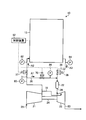
- FIG. 2 is a schematic diagram showing a gas turbine, SOFC, and piping system in a power generation system according to an embodiment of the present invention.
- compressed air discharged from the compressor 21 is supplied to both the SOFC 13 and the combustor 22. Further, the compressed air discharged from the compressor 21 is supplied to the turbine 23 using the cooling air supply line 72 and is also used as air for cooling the turbine 23.
- the easiness of air flow of the SOFC 13 varies due to various reasons such as variations in the driving state of the fuel cell and the gas turbine. If the easiness of air flow in the SOFC 13 varies, the relationship between the ratio of the compressed air A2 supplied to the SOFC 13 and the ratio of the compressed air A1 supplied to the combustor 22 in the compressed air discharged from the compressor 21 It fluctuates and the pressure of the compressed air A2 supplied to the SOFC 13 fluctuates.
- the control valve 37 that adjusts the ease of flow of the compressed air A2 in the second compressed air supply line 31 and the compression of the first compressed air supply line 26.
- a bypass control valve (control valve) 70 that adjusts the ease of flow of air A1 and pressure detectors 80, 82, 84, and 86 are provided.
- the pressure detectors 80, 82, 84, and 86 serve as detectors that detect the ease of flow of the compressed air of the SOFC 13 of the present embodiment.
- the control device (control unit) 62 of the power generation system 10 drives the control valve 37 and the bypass control valve 70 based on the detection results of the pressure detection units 80, 82, 84, 86.
- the power generation system 10 detects the ease of flow of the compressed air in the SOFC 13 based on the difference between the pressure of the compressed air A2 detected by the pressure detector 82 and the pressure of the compressed air A3 detected by the pressure detector 84.
- the opening degree of the control valve 37 and the bypass control valve 70 is controlled based on the detection result. By this control, the balance between the ease of flow of the compressed air A1 in the first compressed air supply line 26 and the ease of flow of the compressed air A2 in the second compressed air supply line 31 can be adjusted. Thereby, the pressure of the compressed air A2 supplied to the SOFC 13 can be stabilized.
- the bypass control valve 70 is installed in the first compressed air supply line 26.
- the bypass control valve 70 switches the opening and closing of the bypass control valve 70 to switch the flow of the compressed air A1 to the first compressed air supply line 26, and the flow of the compressed air A1 flowing through the first compressed air supply line 26 by adjusting the opening degree.
- the ease, flow rate, and pressure difference between the upstream and downstream of the bypass control valve 70 are controlled.
- the control valve 37 is installed in the 2nd compressed air supply line 31 as mentioned above, and the same adjustment as the bypass control valve 70 is performed to the 2nd compressed air supply line 31 by adjusting opening and closing and an opening degree. be able to.
- the pressure detector 80 is provided in a line where compressed air is discharged from the compressor 21. Specifically, it is provided on the line before branching to the first compressed air supply line 26 and the second compressed air supply line 31.
- the pressure detector 80 detects the pressure of the compressed air discharged from the compressor 21.
- the pressure detector 82 is disposed downstream of the control valve 37 in the second compressed air supply line 31 and upstream of the SOFC 13.
- the pressure detector 82 detects the pressure of the compressed air A2 supplied to the SOFC 13.
- the pressure detection unit 84 is disposed downstream of the SOFC 13 in the compressed air circulation line 36 and upstream of the control valve 38.
- the pressure detector 84 detects the pressure of the compressed air A3 discharged from the SOFC 13.
- the pressure detector 86 is disposed downstream of the bypass control valve 70 of the first compressed air supply line 26 and upstream of the connecting portion of the compressed air circulation line 36. The pressure detector 86 detects the pressure of the compressed air A1 after passing through the bypass control valve 70.
- the control device 62 can adjust the opening degree of at least one of the control valve 37 and the bypass control valve 70. Therefore, the control device 62 can adjust the ease of flow of the compressed air of at least one of the first compressed air supply line 26 and the second compressed air supply line 31. Thereby, the balance between the ease of flow of the compressed air A1 in the first compressed air supply line 26 and the ease of flow of the compressed air A2 in the second compressed air supply line 31 can be adjusted.
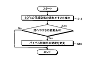
- FIG. 3 is a flowchart illustrating an example of the driving operation of the power generation system according to the present embodiment.
- the driving operation shown in FIG. 3 can be realized by the control device (control unit) 62 executing arithmetic processing based on the detection result of each unit. Note that the control device 62 repeatedly executes the process shown in FIG.
- the control device 62 detects the ease of flow of the compressed air of the SOFC 13 (step S12). Specifically, pressure loss in the SOFC 13 is detected based on at least the detection results of the pressure detector 82 and the pressure detector 84, and the ease of flow of compressed air in the SOFC 13 is detected based on the result. More preferably, considering the results of the pressure detection unit 80 and the pressure detection unit 84, the SOFC 13 is calculated by calculating the pressure balance in the air-side path of the power generation system 10, the flow path resistance of each unit, and the like. Detects the ease of flow of compressed air.
- control device 62 When the control device 62 detects the ease of flow of the compressed air in the SOFC 13, it determines whether there is a change in the ease of flow (step S14). For example, the control device 62 determines that there is a change when the difference from the ease of flow when the previous adjustment is performed exceeds a set threshold value. If it is determined that there is no change (No in step S14), the control device 62 ends this process.
- Step S16 When it is determined that there is a change (Yes in Step S14), the control device 62 performs control to change the opening degree of the bypass control valve 70 (Step S16), and ends this process.
- the control device 62 performs control to reduce the opening degree of the bypass control valve 70, and when it is determined that the compressed air is less likely to flow in the SOFC 13, bypass control is performed. Control to increase the opening of the valve 70 is performed.
- the power generation system 10 controls the pressure fluctuation of the compressed air A2 supplied to the SOFC 13 by adjusting the opening degree of the bypass control valve 70 based on the ease of flow of the compressed air in the SOFC 13, and the air of the SOFC 13
- the pressure fluctuation on the pole side can be suppressed. For this reason, the pressure balance between the air electrode and the fuel electrode of the SOFC 13 can be kept constant.
- the amount and pressure of compressed air supplied to the combustor 22 may fluctuate. If the compressed air supplied to the combustor 22 fluctuates, the combustion of the fuel gas in the combustor 22 becomes unstable.
- the power generation system 10 adjusts the opening degree of the bypass control valve 70 in accordance with fluctuations in the ease of flow of the compressed air in the SOFC 13, thereby compressing the compressed air A ⁇ b> 2 supplied to the SOFC 13 and the compressed air supplied to the fuel unit 22. It can suppress that the balance of A1 fluctuates. Thereby, the electric power generation system 10 can also suppress the fluctuation
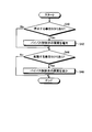
- FIG. 4 is a flowchart illustrating another example of the driving operation of the power generation system according to the present embodiment.
- the driving operation shown in FIG. 4 can be realized by the control device (control unit) 62 executing arithmetic processing based on the detection result of each unit.
- the control device (control unit) 62 detects the abnormality in the SOFC 13 or the gas turbine 11, and executes the processing shown in FIG. 4 when stopping the flow of the exhaust fuel gas and the compressed air between the SOFC 13 and the gas turbine 11. To do.
- control device 62 detects an abnormality in the SOFC 13 or the gas turbine 11 (step S20)
- the control device 62 controls to reduce the opening degree of the control valve 32 of the second compressed air supply line 31 and the control valve 38 of the compressed air circulation line 36. (Step S22) and control to increase the opening degree of the bypass control valve 70 (step S24).
- the control device 62 determines whether or not the control valve 32 of the second compressed air supply line 31 and the control valve 38 of the compressed air circulation line 36 have been closed (step S26). When it is determined that the closing is not completed (No in Step S26), the control device 62 returns to Step S22, and when it is determined that the closing is completed (Yes in Step S26), this process ends.
- the power generation system 10 closes the control valve 32 of the second compressed air supply line 31 and the control valve 38 of the compressed air circulation line 36, and compressed air to the SOFC 13.
- the supply of A2 and the discharge of compressed air (exhaust air) A3 from the SOFC 13 are stopped. Therefore, the SOFC 13 can be isolated from the gas turbine 11, and the pressure fluctuation on the air electrode side of the SOFC 13 can be suppressed. For this reason, the pressure balance between the air electrode and the fuel electrode of the SOFC 13 can be kept constant.
- the power generation system 10 detects the pressure of each line by the pressure detection unit, and detects the ease of flow of the compressed air based on the detected pressure (pressure difference), but is not limited thereto.
- FIG. 5 is a schematic diagram showing another example of the gas turbine, the SOFC, and the piping system.
- the SOFC 113 includes a plurality of unit SOFC units 120.
- the plurality of unit SOFC units 120 are arranged in parallel, are supplied with compressed air A2 from the second compressed air supply line 31, and discharge the compressed air A3 to the compressed air circulation line 36.
- the unit SOFC unit 120 includes an upstream branch pipe 121, a unit SOFC 122, a downstream branch pipe 124, and control valves 126 and 128.
- the upstream branch pipe 121 has one end connected to the second compressed air supply line 31 and the other end connected to the unit SOFC 122.
- the unit SOFC 122 has the same configuration as the SOFC 13 described above, and reacts at a predetermined operating temperature by supplying high-temperature fuel gas as a reducing agent and high-temperature air (oxidizing gas) as an oxidant. Power generation.
- This unit SOFC 122 is configured by accommodating an air electrode, a solid electrolyte, and a fuel electrode in a pressure vessel.
- the unit SOFC 122 is supplied with compressed air A2 from the upstream branch pipe 121.
- the downstream branch pipe 124 has one end connected to the unit SOFC 122 and the other end connected to the compressed air circulation line 36.
- the unit SOFC unit 120 is supplied with compressed air A2 from the second compressed air supply line 31 through the upstream branch pipe 121 to the unit SOFC 122. Further, the unit SOFC unit 120 passes through the downstream branch pipe 124 from the unit SOFC 122, and the compressed air A3 is discharged to the compressed air circulation line 36.
- the control valve 126 is disposed in the upstream branch pipe 121.
- the control valve 126 adjusts the compressed air A ⁇ b> 2 flowing through the upstream branch pipe 121 by adjusting the opening and closing and the opening degree, similarly to the control valves described above.
- the control valve 128 is disposed in the downstream branch pipe 124. As with the control valve described above, the control valve 128 adjusts the compressed air A3 flowing through the downstream branch pipe 124 by adjusting the opening and closing and the opening degree.
- the unit SOFC unit 120 is configured as described above. By closing the control valves 126 and 128, one unit SOFC unit 120 can be isolated from the path through which the compressed air flows. As a result, the SOFC 113 can switch between driving and stopping for each unit SOFC unit 120, and only one unit SOFC unit 120 can be maintained or replaced while generating power in the other unit SOFC unit 120.
- the control device 62 acquires information on the number of unit SOFC units 120 (unit SOFC 122) that are driven or stopped and information on switching between starting and stopping of the unit SOFC unit 120 as information on the ease of flow of compressed air in the SOFC 113,
- the bypass control valve 70 may be controlled.
- FIG. 6 is a flowchart illustrating an example of the driving operation of the power generation system 10a.
- the control device 62 determines whether there is a unit SOFC 122 to be stopped (step S40). When it is determined that there is a unit SOFC 122 to be stopped (Yes in Step S40), the control device 62 performs control to increase the opening degree of the bypass control valve 70 (Step S42). Thereby, the unit SOFC unit 120 is stopped, so that the compressed air A2 that is no longer used in the SOFC 113 can be supplied to the combustor 22 side. Thereby, even if the unit SOFC 122 stops, the pressure fluctuation of the compressed air A2 supplied to the unit SOFC 122 can be suppressed, and the pressure fluctuation on the air electrode side of the unit SOFC 122 can be suppressed.
- the control device 62 determines whether there is a unit SOFC 122 to be activated (step S42). S44). When it is determined that there is a unit SOFC 122 to be activated (Yes in Step S44), the control device 62 performs control to decrease the opening degree of the bypass control valve 70 (Step S46). Thereby, even if the unit SOFC 122 is newly activated, the pressure fluctuation of the compressed air A2 supplied to the other activated unit SOFC 122 can be suppressed, and the pressure fluctuation on the air electrode side of the unit SOFC 122 can be suppressed. For this reason, the pressure balance between the air electrode and the fuel electrode of the unit SOFC 122 can be kept constant.
- the control device 62 ends this processing when it is determined that there is no unit SOFC 122 to be activated (No in Step S44) or when the opening degree of the bypass control valve is adjusted in Step S46.
- the power generation system 10a varies the pressure of the compressed air A2 supplied to the SOFC 113 by adjusting the opening degree of the bypass control valve 70 in accordance with switching of starting and stopping of the unit SOFC unit 120 (unit SOFC 122). Can be suppressed. Moreover, since the power generation system 10a can adjust the bypass control valve 70 based on the control state of the unit SOFC unit 120, the control becomes simple.
- the opening degree of the bypass control valve 70 was adjusted, this invention is not limited to this.
- the power generation system adjusts the opening degree of the control valve 37 of the second compressed air supply line 31 based on the ease of flow of the compressed air in the SOFC 113, so that the compression supplied from the second compressed air supply line 31 to the SOFC 113 is performed.
- the balance between the air A2 and the compressed air A1 supplied to the combustor 22 from the first compressed air supply line 26 may be adjusted.
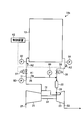
- FIG. 7 is a schematic diagram showing another example of the gas turbine, the SOFC, and the piping system.
- the power generation system 10b shown in FIG. 7 is the same as the power generation system 10 shown in FIG. 2 described above except that the bypass control valve 70 is not provided in the first compressed air supply line 26.
- the power generation system 10b may not include the pressure detection unit 86.
- the power generation system 10b adjusts the control valve 37 based on the ease of flow of compressed air in the SOFC 13, thereby allowing the compressed air A2 to be supplied from the second compressed air supply line 31 to the SOFC 13 and the first compressed air supply line.
- the balance of the compressed air A ⁇ b> 1 supplied from 26 to the combustor 22 is adjusted. Thereby, the balance can be adjusted without providing the bypass control valve 70.
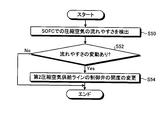
- FIG. 8 is a flowchart showing an example of the drive operation of the power generation system of the power generation system 10b of the present embodiment described above.
- the control device 62 detects the ease of flow of compressed air in the SOFC 13 (step S50).
- the control device 62 determines whether there is a change in the flowability (step S52). If it is determined that there is no change (No in step S52), the control device 62 ends this process.
- Step S52 When it is determined that there is a change (Yes in Step S52), the control device 62 performs control to change the opening degree of the control valve 37 of the second compressed air supply line 31 (Step S54), and ends this process.
- the control device 62 performs control to reduce the opening degree of the control valve 37, and when it is determined that the compressed air is difficult to flow in the SOFC 13, Control to increase the opening of the.
- the power generation system 10b also suppresses the pressure fluctuation of the compressed air A2 supplied to the SOFC 13 by adjusting the opening degree of the control valve 37 based on the ease of flow of the compressed air in the SOFC 13, and the air electrode of the SOFC 13 Side pressure fluctuations can be suppressed. For this reason, the pressure balance between the air electrode and the fuel electrode of the SOFC 13 can be kept constant.
- the ease of air flow in each line is adjusted using a control valve that can adjust the opening, but the present invention is not limited to this.
- the principle and configuration of the power generation system is not particularly limited as long as it is a mechanism (adjustment unit) that can adjust the ease of air flow.
- FIG. 9 is a schematic configuration diagram showing another example of the first compressed air supply line.
- the first compressed air supply line 26 shown in FIG. 9 includes a main pipe 150, a plurality of branch pipes 152, and a plurality of on-off valves 154 as a mechanism (adjustment unit) that can adjust the ease of flow of compressed air. .
- the main pipe 150 is included in a part of the first compressed air supply line 26.
- the main pipe 150 sends the compressed air supplied from the compressor 21 toward the combustor 22.
- the branch pipe 152 is a pipe having one end connected to the main pipe 150 and the other end connected to the main pipe 150. That is, the branch pipe 152 is a pipe that bypasses the main pipe 150.
- the plurality of branch pipes 152 are formed in parallel.
- the compressed air A ⁇ b> 1 flowing through the first compressed air supply line 26 flows through only one of the main pipe 150 and the plurality of branch pipes 152 during circulation in a range bypassed by the branch pipe 152.
- Each branch pipe 152 is provided with one on-off valve 154.
- the on-off valve 154 switches between opening and closing of the installed branch pipe 152.
- the adjusting unit shown in FIG. 9 adjusts the ease of flow of the compressed air A1 in the first compressed air supply line 26 by adjusting the ratio of the number of the open / close valves 154 in the open state to the number of the open / close valves 154 in the closed state. can do. Specifically, increasing the number of open / close valves 154 facilitates the flow of compressed air A1, and reducing the number of open / close valves 154 reduces the flow of compressed air A1.
Landscapes
- Life Sciences & Earth Sciences (AREA)
- Engineering & Computer Science (AREA)
- Manufacturing & Machinery (AREA)
- Sustainable Development (AREA)
- Sustainable Energy (AREA)
- Chemical & Material Sciences (AREA)
- Chemical Kinetics & Catalysis (AREA)
- Electrochemistry (AREA)
- General Chemical & Material Sciences (AREA)
- Fuel Cell (AREA)
Abstract
Description
11 ガスタービン
12 発電機
13、113 固体酸化物形燃料電池(SOFC)
14 蒸気タービン
15 発電機
21 圧縮機
22 燃焼器
23 タービン
25 空気取り込みライン
26 第1圧縮空気供給ライン
27 第1燃料ガス供給ライン
31 第2圧縮空気供給ライン
32 制御弁
33、48 ブロワ
34 排空気ライン
36 圧縮空気循環ライン
38 制御弁
41 第2燃料ガス供給ライン
42 制御弁
43 排燃料ライン
44 排出ライン
45 排燃料ガス供給ライン
47 制御弁
49 燃料ガス再循環ライン
50 再循環ブロワ
51 排熱回収ボイラ
52 タービン
53 排ガスライン
54 蒸気供給ライン
55 給水ライン
56 復水器
57 給水ポンプ
62 制御装置(制御部)
70 バイパス制御弁
72 冷却空気供給ライン
80、82、84、86 圧力検出部
120 単位SOFCユニット
121 上流分岐管
122 単位SOFC
124 下流分岐管
126、128 制御弁
150 主配管
152 分岐管
154 開閉弁
Claims (11)
- 燃料電池と、
圧縮機と燃焼器を有するガスタービンと、
前記圧縮機から前記燃焼器に圧縮空気を供給する第1圧縮空気供給ラインと、
前記圧縮機から前記燃料電池に圧縮空気を供給する第2圧縮空気供給ラインと、
前記燃料電池から前記燃焼器に排空気を供給する圧縮空気循環ラインと、
前記燃料電池の圧縮空気の流れやすさを検出する検出部と、
前記第1圧縮空気供給ラインの圧縮空気の流れやすさと、前記第2圧縮空気供給ラインの圧縮空気の流れやすさとのバランスを調整する調整部と、
前記検出部で検出した前記燃料電池の圧縮空気の流れやすさの変動に基づいて、前記調整部によって前記第1圧縮空気供給ラインの圧縮空気の流れやすさと、前記第2圧縮空気供給ラインの圧縮空気の流れやすさとのバランスを調整する制御装置と、を有することを特徴とする発電システム。 - 前記調整部は、前記第1圧縮空気供給ラインに配置された、前記第1圧縮空気供給ラインの圧縮空気の流れやすさを調整する機構を含むことを特徴とする請求項1に記載の発電システム。
- 前記調整部は、前記第1圧縮空気供給ラインに配置された、開度を調整可能な制御弁を含むことを特徴とする請求項2に記載の発電システム。
- 前記調整部は、前記第1圧縮空気供給ラインに配置された、主配管と、前記主配管をバイパスする少なくとも1本の分岐管と、前記分岐管に配置された開閉弁と、を含むことを特徴とする請求項2に記載の発電システム。
- 前記制御装置は、前記燃料電池に圧縮空気が流れにくくなった場合、前記第1圧縮空気供給ラインに圧縮空気を流れやすくすることを特徴とする請求項1から請求項4のいずれか一項に記載の発電システム。
- 前記調整部は、前記第2圧縮空気供給ラインに配置された、前記第2圧縮空気供給ラインの圧縮空気の流れやすさを調整する機構を含むことを特徴とする請求項1から請求項5のいずれか一項に記載の発電システム。
- 前記調整部は、前記第2圧縮空気供給ラインに配置された、開度を調整可能な制御弁を含むことを特徴とする請求項6に記載の発電システム。
- 前記制御装置は、前記燃料電池に圧縮空気が流れにくくなった場合、前記第2圧縮空気供給ラインに圧縮空気を流れにくくすることを特徴とする請求項1から請求項7のいずれか一項に記載の発電システム。
- 前記制御装置は、前記燃料電池と前記ガスタービンの圧縮空気の流通経路を遮断すると判定した場合、前記調整部によって、前記第2圧縮空気供給ラインに圧縮空気を流れにくくしつつ、前記第1圧縮空気供給ラインに圧縮空気を流れやすくする制御を繰り返し、前記第2圧縮空気供給ラインを閉鎖させることを特徴とする請求項1から請求項8のいずれか一項に記載の発電システム。
- 前記検出部は、前記第1圧縮空気供給ラインを流れる圧縮空気の圧力を検出する第1圧力検出部と、前記圧縮空気循環ラインを流れる圧縮空気の圧力を検出する第2圧力検出部と、を含み、前記第1圧力検出部で検出した結果と、前記第2圧力検出部で検出した結果とに基づいて、前記燃料電池の圧縮空気の流れやすさを検出することを特徴とする請求項1から9のいずれか一項に記載の発電システム。
- 燃料電池と、圧縮機と燃焼器を有するガスタービンと、前記圧縮機から前記燃焼器に圧縮空気を供給する第1圧縮空気供給ラインと、前記圧縮機から前記燃料電池に圧縮空気を供給する第2圧縮空気供給ラインと、前記燃料電池から前記燃焼器に排空気を供給する圧縮空気循環ラインと、を有する発電システムの運転方法であって、
前記燃料電池の圧縮空気の流れやすさを検出する工程と、
前記検出部で検出した前記燃料電池の圧縮空気の流れやすさの変動に基づいて、前記調整部によって前記第1圧縮空気供給ラインの圧縮空気の流れやすさと、前記第2圧縮空気供給ラインの圧縮空気の流れやすさとのバランスを調整する工程、を有することを特徴とする発電システムの運転方法。
Priority Applications (4)
| Application Number | Priority Date | Filing Date | Title |
|---|---|---|---|
| CN201380055248.1A CN104737347B (zh) | 2012-11-22 | 2013-11-12 | 发电系统以及发电系统的运行方法 |
| DE112013005601.1T DE112013005601T5 (de) | 2012-11-22 | 2013-11-12 | Stromerzeugungssystem und Verfahren zum Betrieb eines Stromerzeugungssystems |
| US14/436,281 US20150244007A1 (en) | 2012-11-22 | 2013-11-12 | Power generation system and method of operating power generation system |
| KR1020157010212A KR20150058459A (ko) | 2012-11-22 | 2013-11-12 | 발전 시스템 및 발전 시스템의 운전 방법 |
Applications Claiming Priority (2)
| Application Number | Priority Date | Filing Date | Title |
|---|---|---|---|
| JP2012256907A JP6116871B2 (ja) | 2012-11-22 | 2012-11-22 | 発電システム及び発電システムの運転方法 |
| JP2012-256907 | 2012-11-22 |
Publications (1)
| Publication Number | Publication Date |
|---|---|
| WO2014080801A1 true WO2014080801A1 (ja) | 2014-05-30 |
Family
ID=50775984
Family Applications (1)
| Application Number | Title | Priority Date | Filing Date |
|---|---|---|---|
| PCT/JP2013/080572 Ceased WO2014080801A1 (ja) | 2012-11-22 | 2013-11-12 | 発電システム及び発電システムの運転方法 |
Country Status (6)
| Country | Link |
|---|---|
| US (1) | US20150244007A1 (ja) |
| JP (1) | JP6116871B2 (ja) |
| KR (1) | KR20150058459A (ja) |
| CN (1) | CN104737347B (ja) |
| DE (1) | DE112013005601T5 (ja) |
| WO (1) | WO2014080801A1 (ja) |
Families Citing this family (10)
| Publication number | Priority date | Publication date | Assignee | Title |
|---|---|---|---|---|
| US10033056B2 (en) * | 2015-09-13 | 2018-07-24 | Honeywell International Inc. | Fuel cell regulation using loss recovery systems |
| US9739199B2 (en) * | 2015-10-30 | 2017-08-22 | General Electric Company | Intercooled gas turbine optimization |
| JP6786233B2 (ja) * | 2016-03-22 | 2020-11-18 | 三菱パワー株式会社 | ガスタービンの特性評価装置及びガスタービンの特性評価方法 |
| CA3018246C (en) * | 2016-03-22 | 2019-08-06 | Nissan Motor Co., Ltd. | Fuel cell system and method for controlling fuel cell system |
| JP7211760B2 (ja) * | 2018-10-23 | 2023-01-24 | 一般財団法人電力中央研究所 | 発電設備 |
| US11129159B2 (en) * | 2019-04-11 | 2021-09-21 | Servicenow, Inc. | Programmatic orchestration of cloud-based services |
| JP6961736B2 (ja) * | 2020-02-27 | 2021-11-05 | 三菱パワー株式会社 | 燃料電池システム及びその制御方法 |
| KR20230024142A (ko) * | 2021-08-11 | 2023-02-20 | 현대자동차주식회사 | 연료전지 시스템 |
| US12169069B2 (en) * | 2021-12-20 | 2024-12-17 | General Electric Company | System for producing diluent for a gas turbine engine |
| DE102022202175A1 (de) * | 2022-03-03 | 2023-09-07 | Robert Bosch Gesellschaft mit beschränkter Haftung | Brennstoffzellensystem mit Energierekuperation |
Citations (3)
| Publication number | Priority date | Publication date | Assignee | Title |
|---|---|---|---|---|
| JP2009035455A (ja) * | 2007-08-02 | 2009-02-19 | Sumco Techxiv株式会社 | 半導体単結晶の製造装置 |
| JP2009205932A (ja) * | 2008-02-27 | 2009-09-10 | Mitsubishi Heavy Ind Ltd | コンバインドシステム |
| JP2010146934A (ja) * | 2008-12-22 | 2010-07-01 | Mitsubishi Heavy Ind Ltd | 固体酸化物形燃料電池および固体酸化物形燃料電池システム |
Family Cites Families (1)
| Publication number | Priority date | Publication date | Assignee | Title |
|---|---|---|---|---|
| JP4806886B2 (ja) * | 2003-05-16 | 2011-11-02 | トヨタ自動車株式会社 | 燃料電池システムの運転制御 |
-
2012
- 2012-11-22 JP JP2012256907A patent/JP6116871B2/ja active Active
-
2013
- 2013-11-12 DE DE112013005601.1T patent/DE112013005601T5/de active Pending
- 2013-11-12 US US14/436,281 patent/US20150244007A1/en not_active Abandoned
- 2013-11-12 KR KR1020157010212A patent/KR20150058459A/ko not_active Ceased
- 2013-11-12 WO PCT/JP2013/080572 patent/WO2014080801A1/ja not_active Ceased
- 2013-11-12 CN CN201380055248.1A patent/CN104737347B/zh active Active
Patent Citations (3)
| Publication number | Priority date | Publication date | Assignee | Title |
|---|---|---|---|---|
| JP2009035455A (ja) * | 2007-08-02 | 2009-02-19 | Sumco Techxiv株式会社 | 半導体単結晶の製造装置 |
| JP2009205932A (ja) * | 2008-02-27 | 2009-09-10 | Mitsubishi Heavy Ind Ltd | コンバインドシステム |
| JP2010146934A (ja) * | 2008-12-22 | 2010-07-01 | Mitsubishi Heavy Ind Ltd | 固体酸化物形燃料電池および固体酸化物形燃料電池システム |
Also Published As
| Publication number | Publication date |
|---|---|
| CN104737347B (zh) | 2017-12-12 |
| US20150244007A1 (en) | 2015-08-27 |
| DE112013005601T5 (de) | 2015-10-22 |
| CN104737347A (zh) | 2015-06-24 |
| KR20150058459A (ko) | 2015-05-28 |
| JP2014107031A (ja) | 2014-06-09 |
| JP6116871B2 (ja) | 2017-04-19 |
Similar Documents
| Publication | Publication Date | Title |
|---|---|---|
| JP6116871B2 (ja) | 発電システム及び発電システムの運転方法 | |
| JP6100012B2 (ja) | 発電システム及び発電システムの運転方法 | |
| JP6071430B2 (ja) | 発電システム及び発電システムの運転方法 | |
| JP6053560B2 (ja) | 発電システム及び発電システムの運転方法 | |
| JP6228752B2 (ja) | 発電システム及び発電システムの起動方法 | |
| WO2014069413A1 (ja) | 発電システム及び発電システムにおける燃料電池の起動方法 | |
| WO2014069408A1 (ja) | 発電システム及び発電システムにおける燃料電池の起動方法並びに運転方法 | |
| JP6071428B2 (ja) | 発電システム及び発電システムにおける燃料電池の起動方法 | |
| JP6125221B2 (ja) | 発電システム及び発電システムの運転方法 | |
| CN104737346B (zh) | 发电系统以及发电系统的运转方法 | |
| JP6049421B2 (ja) | 発電システム及び発電システムの運転方法 | |
| WO2014112210A1 (ja) | 発電システム | |
| JP6087591B2 (ja) | 発電システム及び発電システムにおける燃料電池の起動方法 | |
| JP6057670B2 (ja) | 発電システム及び発電システムにおける燃料電池の運転方法 | |
| JP6087585B2 (ja) | 発電システム及び発電システムにおける燃料電池の起動方法 | |
| JP2015115195A (ja) | 発電システム及び発電システムの運転方法 |
Legal Events
| Date | Code | Title | Description |
|---|---|---|---|
| 121 | Ep: the epo has been informed by wipo that ep was designated in this application |
Ref document number: 13857486 Country of ref document: EP Kind code of ref document: A1 |
|
| WWE | Wipo information: entry into national phase |
Ref document number: 14436281 Country of ref document: US |
|
| ENP | Entry into the national phase |
Ref document number: 20157010212 Country of ref document: KR Kind code of ref document: A |
|
| WWE | Wipo information: entry into national phase |
Ref document number: 112013005601 Country of ref document: DE Ref document number: 1120130056011 Country of ref document: DE |
|
| 122 | Ep: pct application non-entry in european phase |
Ref document number: 13857486 Country of ref document: EP Kind code of ref document: A1 |