WO2014076925A1 - 投写用ズームレンズおよび投写型表示装置 - Google Patents
投写用ズームレンズおよび投写型表示装置 Download PDFInfo
- Publication number
- WO2014076925A1 WO2014076925A1 PCT/JP2013/006615 JP2013006615W WO2014076925A1 WO 2014076925 A1 WO2014076925 A1 WO 2014076925A1 JP 2013006615 W JP2013006615 W JP 2013006615W WO 2014076925 A1 WO2014076925 A1 WO 2014076925A1
- Authority
- WO
- WIPO (PCT)
- Prior art keywords
- lens
- lens group
- zooming
- projection
- zoom lens
- Prior art date
- Legal status (The legal status is an assumption and is not a legal conclusion. Google has not performed a legal analysis and makes no representation as to the accuracy of the status listed.)
- Ceased
Links
Images











Classifications
-
- G—PHYSICS
- G02—OPTICS
- G02B—OPTICAL ELEMENTS, SYSTEMS OR APPARATUS
- G02B15/00—Optical objectives with means for varying the magnification
- G02B15/14—Optical objectives with means for varying the magnification by axial movement of one or more lenses or groups of lenses relative to the image plane for continuously varying the equivalent focal length of the objective
- G02B15/146—Optical objectives with means for varying the magnification by axial movement of one or more lenses or groups of lenses relative to the image plane for continuously varying the equivalent focal length of the objective having more than five groups
- G02B15/1465—Optical objectives with means for varying the magnification by axial movement of one or more lenses or groups of lenses relative to the image plane for continuously varying the equivalent focal length of the objective having more than five groups the first group being negative
-
- G—PHYSICS
- G02—OPTICS
- G02B—OPTICAL ELEMENTS, SYSTEMS OR APPARATUS
- G02B13/00—Optical objectives specially designed for the purposes specified below
- G02B13/04—Reversed telephoto objectives
-
- G—PHYSICS
- G02—OPTICS
- G02B—OPTICAL ELEMENTS, SYSTEMS OR APPARATUS
- G02B27/00—Optical systems or apparatus not provided for by any of the groups G02B1/00 - G02B26/00, G02B30/00
- G02B27/0025—Optical systems or apparatus not provided for by any of the groups G02B1/00 - G02B26/00, G02B30/00 for optical correction, e.g. distorsion, aberration
-
- G—PHYSICS
- G02—OPTICS
- G02B—OPTICAL ELEMENTS, SYSTEMS OR APPARATUS
- G02B13/00—Optical objectives specially designed for the purposes specified below
- G02B13/16—Optical objectives specially designed for the purposes specified below for use in conjunction with image converters or intensifiers, or for use with projectors, e.g. objectives for projection TV
-
- G—PHYSICS
- G02—OPTICS
- G02B—OPTICAL ELEMENTS, SYSTEMS OR APPARATUS
- G02B13/00—Optical objectives specially designed for the purposes specified below
- G02B13/22—Telecentric objectives or lens systems
-
- G—PHYSICS
- G02—OPTICS
- G02B—OPTICAL ELEMENTS, SYSTEMS OR APPARATUS
- G02B27/00—Optical systems or apparatus not provided for by any of the groups G02B1/00 - G02B26/00, G02B30/00
- G02B27/64—Imaging systems using optical elements for stabilisation of the lateral and angular position of the image
- G02B27/646—Imaging systems using optical elements for stabilisation of the lateral and angular position of the image compensating for small deviations, e.g. due to vibration or shake
Definitions
- the present invention relates to a zoom lens, and more particularly to a projection zoom lens applied to a projection display device.
- the present invention also relates to a projection display device equipped with such a projection zoom lens.
- projection display devices using light valves such as liquid crystal display elements and DMD (Digital Micromirror Device: registered trademark) have been widely used.
- movie projectors and the like are also using such projection display devices that can project higher-definition images that can be applied to large screens.
- the projection display device used in the above-mentioned movie theater or the like three light valves are provided for each primary color, the light flux from the light source is separated into the three primary colors by the color separation optical system, Since a three-plate system is employed in which the light is passed through the light valve and then combined and projected by a color combining optical system, it is required to have a long back focus and good telecentricity.
- the projection image aspect ratio (cinesco size, vista size, etc.) depends on the projection distance and screen size that differ for each movie theater or hall. Accordingly, in order to adapt the size of the display image to the screen size, a zoom lens having a high zoom ratio is required as a projection lens.
- this kind of zoom lens has an aperture.
- a function for keeping the number (hereinafter, also referred to as “F number”) constant in the entire zooming region is required.
- Patent Documents 1 to 5 describe zoom lenses that are premised on application to projection display devices. More specifically, Patent Document 1 discloses a first lens group that has negative refractive power and is disposed on the most enlargement side, and a final lens group that has positive refractive power and is disposed on the most reduction side. A zoom lens for projection having a 6-group configuration in which is fixed during zooming and an aperture stop is disposed in the fourth lens group is shown.
- Patent Document 2 discloses a projection zoom lens that keeps the numerical aperture constant so that the lens group on the reduction side of the aperture stop is not moved during zooming.
- Patent Document 3 the first lens group having the negative refracting power and arranged closest to the enlargement side and the final lens group having the positive refracting power and arranged closest to the reduction side are zoomed.
- a projection zoom lens is described in which a numerical aperture is fixed in the entire zooming region by using a variable diaphragm whose aperture diameter changes with zooming. Yes.
- Patent Documents 4 and 5 a first lens group having a positive refractive power and disposed on the most magnification side, and a final lens group having a positive refractive power and disposed on the most reduction side are disclosed.
- the projection zoom lens disclosed in Patent Document 1 does not have a function of keeping the numerical aperture constant during zooming.
- This projection zoom lens also has a short back focus.
- the zoom lens for projection described in Patent Document 2 in which the numerical aperture is kept constant without moving the lens group on the reduction side from the aperture stop at the time of zooming is a sufficiently high zooming power sufficient as a zoom lens for projection.
- the ratio is not guaranteed.
- the projection zoom lens having such a configuration tends to have a large lens outer diameter and total length on the enlargement side, so that the installation conditions are strict and the cost tends to be high.
- the projection zoom lens described in Patent Document 3 in which the numerical aperture is kept constant by a variable stop has a sufficiently high zoom ratio, but does not have a sufficiently long back focus. This is disadvantageous in arranging an optical system using a prism.
- the projection zoom lens disclosed in Patent Documents 4 and 5 moves the lens group on the enlargement side relative to the aperture stop in order to keep the numerical aperture constant, and the aperture stop and the lens group on the reduction side therefor are Since they are fixed, the total length and the lens diameter of the most magnified lens group tend to be large.
- the present invention has been made in view of the above circumstances, a projection zoom lens capable of making the numerical aperture constant in the entire zoom region, and ensuring a high zoom ratio and a sufficiently long back focus, and
- An object of the present invention is to provide a projection display device.
- a first projection zoom lens includes: A first lens group having a negative refractive power, which is arranged in order from the magnification side, a second lens group having a positive refractive power that moves along the optical axis upon zooming, and at the time of zooming A third lens group having a positive refractive power that moves along the optical axis, a fourth lens group having a positive refractive power that moves along the optical axis upon zooming, and an optical axis upon zooming.
- a projection zoom lens comprising a fifth lens group that moves along a sixth lens group that has a positive refractive power
- the reduction side is configured to be telecentric
- the numerical aperture of the zoom lens is configured to be constant in the entire zoom region
- the amount of movement during zooming from the wide-angle end to the telephoto end of the fourth lens group is the maximum among all the lens groups
- the absolute values of the moving amounts at the time of zooming from the wide-angle end to the telephoto end of the second, third, fourth, and fifth lens groups are m2, m3, m4, and m5, respectively, and the focal length of the entire system at the wide-angle end is fw
- the following conditional expressions (1) and (2) 1.9 ⁇ m4 / fw (1) 0.7 ⁇ (m3 + m4) / (m2 + m3 + m4 + m5) (2) It is characterized by satisfying.
- substantially, consisting of the sixth lens group means a lens having substantially no power other than the lens group mentioned therein, a lens such as an aperture or a cover glass. This includes cases where there are other optical elements, lens flanges, lens barrels, imaging elements, camera shake correction mechanisms, and the like. The same applies to the second projection zoom lens of the present invention described below.
- the above-mentioned “reduction side is telecentric” means that the bisector of the upper maximum ray and the lower maximum ray in the cross section of the light beam condensed at an arbitrary point on the reduction side image plane is the optical axis. Refers to a state close to parallel, and is not limited to a case where it is completely telecentric, that is, not only when the bisector is completely parallel to the optical axis, but also includes cases where there is some error. Means.
- the case where there is a slight error is a case where the inclination of the bisector is within ⁇ 3 ° with respect to the optical axis. The same applies to the second projection zoom lens of the present invention described below.
- the second projection zoom lens according to the present invention is: A first lens group having a negative refractive power, which is arranged in order from the magnification side, a second lens group having a positive refractive power that moves along the optical axis upon zooming, and at the time of zooming A third lens group having a positive refractive power that moves along the optical axis, a fourth lens group having a positive refractive power that moves along the optical axis upon zooming, and an optical axis upon zooming.
- a projection zoom lens comprising a fifth lens group that moves along a sixth lens group that has a positive refractive power,
- the fifth lens group has negative refractive power;
- the reduction side is configured to be telecentric,
- the numerical aperture of the zoom lens is configured to be constant in the entire zoom region,
- the amount of movement during zooming from the wide-angle end to the telephoto end of the fourth lens group is the maximum among all the lens groups,
- the following conditional expression (1) 1.9 ⁇ m4 / fw (1) It is characterized by satisfying.
- the absolute values of the movement amounts during zooming from the wide-angle end to the telephoto end of the second, third, fourth and fifth lens groups are m2, m3, m4 and m5, respectively.
- conditional expression (2) 0.7 ⁇ (m3 + m4) / (m2 + m3 + m4 + m5) (2) It is desirable that
- An aperture stop is disposed on the reduction side of the third lens group and on the enlargement side of the fifth lens group;
- f4 is the focal length of the fourth lens group
- fw is the focal length of the entire system at the wide-angle end. 3.0 ⁇ f4 / fw ⁇ 5.5 (3) It is desirable that
- the aperture stop disposed on the reduction side of the third lens group and the enlargement side of the fifth lens group is a variable stop whose aperture diameter changes upon zooming.
- the aperture stop disposed on the reduction side of the third lens group and on the enlargement side of the fifth lens group may move in the optical axis direction independently of the other lenses during zooming. desirable.
- the aperture stop is disposed on the reduction side of the third lens group and on the enlargement side of the fifth lens group.
- the aperture stop is disposed on the reduction side of the third lens group and on the enlargement side of the fifth lens group.
- the back focus (air conversion distance) on the reduction side of the entire system at the wide angle end is Bf
- the maximum effective image circle diameter (image circle diameter) on the reduction side is Im ⁇
- the projection distance is infinite
- L is the distance on the optical axis from the most enlargement side lens surface to the most reduction side lens surface: 2.5 ⁇ Bf / Im ⁇ (4) L / Im ⁇ ⁇ 12 (5)
- the aperture stop is disposed on the reduction side of the third lens group and on the enlargement side of the fifth lens group.
- the second lens group includes a lens having negative refractive power.
- the aperture stop is disposed on the reduction side of the third lens group and on the enlargement side of the fifth lens group.
- the third lens group includes a lens having negative refractive power.
- the aperture stop is disposed on the reduction side of the third lens group and on the enlargement side of the fifth lens group. If 3) is met,
- the fourth lens group includes a lens having positive refractive power; Then, when the Abbe number of the lens medium having the positive refractive power is ⁇ p, the following conditional expression (6) 60 ⁇ p (6) It is desirable that
- the aperture stop is disposed on the reduction side of the third lens group and on the enlargement side of the fifth lens group.
- the fifth lens group includes, in order from the enlargement side, a lens array having negative refractive power, a lens having positive refractive power, and a lens having negative refractive power.
- a cemented lens may be used as the lens constituting each lens group.
- the cemented lens is configured by bonding of n sheets, the lens is configured as n lenses. It shall be counted.
- the surface shape of the lens and the sign of the refractive power are considered in the paraxial region when an aspheric surface is included.
- a projection display device includes a light source, a light valve on which light from the light source is incident, and a projection zoom lens that projects an optical image by light modulated by the light valve onto a screen.
- the first or second projection zoom lens according to the present invention described above is applied as the projection zoom lens.
- the amount of movement during zooming from the wide-angle end to the telephoto end of the fourth lens group is maximized among all the lens groups, and the fourth lens group and the second lens group adjacent thereto are arranged.
- Conditional expressions (1) and (2) 1.9 ⁇ m4 / fw (1) 0.7 ⁇ (m3 + m4) / (m2 + m3 + m4 + m5) (2) Therefore, a high zoom ratio can be secured.
- the amount of movement during zooming from the wide-angle end to the telephoto end of the fourth lens unit is maximized among all the lens units, and the zooming of the fourth lens unit is maximized.
- Conditional expression (1) 1.9 ⁇ m4 / fw (1) Therefore, a high zoom ratio can be secured.
- the movement amount at the time of zooming of the fourth lens group and the third lens group adjacent to the fourth lens group is expressed by the conditional expression (2). 0.7 ⁇ (m3 + m4) / (m2 + m3 + m4 + m5) (2) If it is set large enough to satisfy the above, a higher zoom ratio can be secured.
- the first and second projection zoom lenses according to the present invention are configured to distribute most of the zooming function between the third lens group and the fourth lens group, particularly the fourth lens group. Many aberration correction functions can be assigned to the group and the fifth lens group. Therefore, aberration correction can be performed satisfactorily even with a long back focus, making it possible to achieve both a long back focus and a high zoom ratio.
- conditional expression (3) 3.0 ⁇ f4 / fw ⁇ 5.5 (3) Is satisfied, the spherical aberration can be reduced and the size can be reduced. That is, when the value of f4 / fw is 3.0 or less, spherical aberration increases, and when the value is 5.5 or more, the lens diameter is large and the zoom lens is likely to be enlarged, but the conditional expression (3) is satisfied. If so, it is possible to avoid such a problem, to suppress the spherical aberration, and to reduce the size.
- the conditional expression (3) is satisfied particularly when the aperture stop is disposed on the reduction side of the third lens group and on the enlargement side of the fifth lens group.
- the zoom lens can be downsized.
- conditional expression (3) is satisfied particularly when the aperture stop is disposed on the reduction side of the third lens group and on the enlargement side of the fifth lens group.
- a zoom lens applied to a projection display device used in a movie theater or the like is generally required to have an F number smaller than (brighter) than 3.0 in the entire zoom range.
- the projection zoom lens of the invention can meet such a demand. Specific numerical values thereof will be described below with reference to examples.
- a zoom lens applied to the projection display device as described above is required to have a distortion of about 2% in the entire zoom range. Can meet such demands. Specific numerical values thereof will be described below with reference to examples.
- the projection display apparatus of the present invention is the one in which the zoom lens of the present invention as described above is applied as a projection zoom lens. It can be constant in the region.
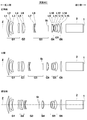
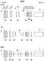
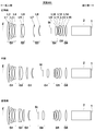
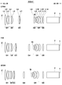
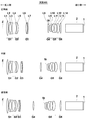
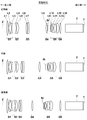
- Sectional drawing which shows the lens structure of the zoom lens for projection which concerns on Example 1 of this invention Sectional drawing which shows the lens structure of the zoom lens for projection which concerns on Example 2 of this invention. Sectional drawing which shows the lens structure of the zoom lens for projection which concerns on Example 3 of this invention. Sectional drawing which shows the lens structure of the zoom lens for projection which concerns on Example 4 of this invention. Sectional drawing which shows the lens structure of the zoom lens for projection which concerns on Example 5 of this invention. Sectional drawing which shows the lens structure of the zoom lens for projection which concerns on Example 6 of this invention. Sectional drawing which shows the lens structure of the zoom lens for projection which concerns on Example 7 of this invention. Sectional drawing which shows the lens structure of the zoom lens for projection which concerns on Example 8 of this invention.
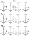
- (A) to (L) are aberration diagrams of the projection zoom lens according to Example 1 described above.
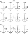
- (A) to (L) are aberration diagrams of the projection zoom lens according to Example 2 described above.
- (A) to (L) are aberration diagrams of the projection zoom lens according to Example 3 described above.
- (A) to (L) are aberration diagrams of the projection zoom lens according to Example 4 described above.
- (A) to (L) are aberration diagrams of the projection zoom lens according to Example 5 described above.
- (A) to (L) are aberration diagrams of the projection zoom lens according to Example 6 described above.
- FIG. 1 is a schematic configuration diagram showing a projection display device according to an embodiment of the present invention. Schematic block diagram showing a projection display apparatus according to another embodiment of the present invention.
- FIG. 1 shows the movement position of each lens group at the wide-angle end and the telephoto end, and the intermediate position when the zooming lens for projection according to Embodiment 1 of the present invention is zoomed. This manner of illustration is common to FIGS.
- FIGS. 2 to 10 are sectional views showing other configuration examples according to the embodiment of the present invention, and correspond to projection zoom lenses according to Examples 2 to 10 described later, respectively.
- the projection zoom lens according to the present embodiment can be mounted on a projection display device for projecting digital images used in movie theaters, and projects image information displayed on a light valve onto a screen, for example. It can be used as a projection lens.
- FIG. 1 shows glass blocks 2 and 1 such as a color synthesis prism (including filters) on the assumption that the left side of the drawing is an enlargement side and the right side is a reduction side and is mounted on a projection display device. Yes.
- FIGS. 2 to 18 Note that the image display surface of the light valve is disposed so as to be positioned on the reduction side surface of the glass block 1, for example.
- a light beam given image information on the image display surface is incident on the projection zoom lens through the glass blocks 2 and 1 and is arranged in the left direction in the figure by the projection zoom lens. Is projected on a screen (not shown).
- a light beam from a light source is separated into three primary colors by a color separation optical system, and three light valves are provided for each primary color. It may be arranged so that a full color image can be displayed.
- the projection zoom lens according to the present embodiment includes a first lens group G1 having a negative refractive power that is disposed closest to the enlargement side and is fixed at the time of zooming, and a reduction after the first lens group G1.
- As a substantial lens group, and the reduction side is telecentric. It is.
- the configuration of the lens group described above is common to the projection zoom lenses shown in FIGS.
- the projection zoom lens is configured to perform focusing by moving the first lens group G1.
- the first lens group G1 is composed of four lenses (first lens L1 to fourth lens L4)
- the second lens group G2 is composed of two lenses (fifth lens L5 and sixth lens).
- L6 the third lens group G3 includes two lenses (seventh lens L7 and eighth lens L8)
- the fourth lens group G4 includes one lens (ninth lens L9) and its enlargement side.
- the fifth lens group G5 includes five lenses (tenth lens L10 to fourteenth lens L14), and the sixth lens group G6 includes one lens (fifteenth lens L15). Become.
- the number of lenses constituting each lens group is not necessarily limited to the example shown in FIG.
- the second lens group G3 is composed of one lens
- the fourth lens group G3 is composed of two lenses
- the sixth lens group G6 is composed of two lenses.
- the aperture stop St disposed in the fourth lens group G4 is a variable stop that changes the aperture diameter so that the numerical aperture of the zoom lens is constant in the entire zoom region. ing. This point is the same in all of Examples 2 to 9, including the case where the arrangement position of the aperture stop St is different.
- an aperture stop whose aperture diameter does not change may be used.
- the amount of movement during zooming from the wide-angle end to the telephoto end of the fourth lens group G4 is the largest among all the lens groups, and the second lens group G2,
- the absolute values of the moving amounts during zooming from the wide-angle end to the telephoto end of the third lens group G3, the fourth lens group G4, and the fifth lens group G5 are m2, m3, m4, and m5, respectively.
- the following conditional expressions (1) and (2) 1.9 ⁇ m4 / fw (1) 0.7 ⁇ (m3 + m4) / (m2 + m3 + m4 + m5) (2) Is satisfied.
- the zoom lens for projection according to the present embodiment can secure a high zoom ratio.
- conditional expressions (1) and (2) and the other conditional expressions (3) to (6) are collectively shown in Table 22 for each example. is there.
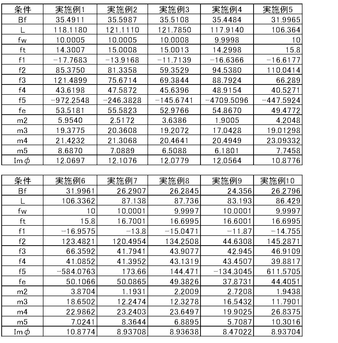
- Table 23 summarizes the conditions related to the conditional expressions (1) to (6) and the values of other main conditions for each example.
- the aperture stop St is disposed on the reduction side of the third lens group G3 and the expansion side of the fifth lens group G5, and the focal length of the fourth lens group G4 is set to f4.
- conditional expression (3 ′) is further satisfied within the range defined by the conditional expression (3), the above effects become more remarkable.
- the back focus (air conversion distance) on the reduction side of the entire system at the wide angle end is Bf
- the maximum effective image circle diameter (image circle diameter) on the reduction side is Im ⁇
- the projection distance The distance on the optical axis from the most magnified lens surface at the infinity (magnification side lens surface of the first lens L1) to the most demagnification side lens surface (reduction side lens surface of the fifteenth lens L15) is defined as L.
- Conditional expressions (4) and (5) below 2.5 ⁇ Bf / Im ⁇ (4) L / Im ⁇ ⁇ 12 (5) Is satisfied.
- conditional expression (5 ') is further satisfied within the range defined by the conditional expression (5), the above effects become more remarkable. In this case, chromatic aberration can be suppressed to a small value. The reason is also as described in detail above.
- the fourth lens group G4 includes a lens (the ninth lens L9) having a positive refractive power, and the Abbe number of the medium of the ninth lens L9 is ⁇ p.
- the Abbe number of each lens is shown in Table 1 described later.
- the projection zoom lens according to this embodiment can reduce axial chromatic aberration.
- the conditional expression (6 ′) and the conditional expression (6 ′′) are satisfied within the range defined by the conditional expression (6). It will be something.
- the projection zoom lens of the embodiment whose sectional view is shown in FIG. 7 corresponds to the projection zoom lens of Example 7 described later.
- the projection zoom lens according to the present embodiment includes a first lens group G1 having a negative refractive power that is disposed closest to the enlargement side and is fixed at the time of zooming, and a reduction after the first lens group G1.
- the configuration of the lens group described above is common to the seventh, eighth, and tenth embodiments.
- the above configuration is basically different in that the fifth lens group G5 has a positive refractive power as compared with the projection zoom lens of FIG. 1 described above.
- the first lens group G1 includes three lenses (first lens L1 to third lens L3), and the second lens group G2 includes two lenses (fourth lens L4 and fifth lens).
- L5 the third lens group G3 is composed of two lenses (sixth lens L6 and seventh lens L7)
- the fourth lens group G4 is composed of one lens (eighth lens L8)
- the lens group G5 includes five lenses (the ninth lens L9 to the thirteenth lens L13) and an aperture stop St disposed on the enlargement side thereof
- the sixth lens group G6 includes one lens (the fourteenth lens L14).
- the number of lenses constituting each lens group is not necessarily limited to the example shown in FIG.
- FIG. 21 is a schematic configuration diagram showing a part of a projection display apparatus according to an embodiment of the present invention.
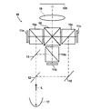
- the projection display device shown in FIG. 21 includes reflective display elements 11a to 11c as light valves corresponding to each color light, dichroic mirrors 12 and 13 for color separation, and a cross dichroic prism 14 for color composition.
- an illumination optical system 10 having a total reflection mirror 18 for deflecting the optical path and polarization separation prisms 15a to 15c.
- a light source 17 that emits white light L is disposed in front of the dichroic mirror 12.
- White light L emitted from the light source 17 is decomposed into three colored light beams (G light, B light, and R light) by the dichroic mirrors 12 and 13.
- the separated color light beams pass through the polarization separation prisms 15a to 15c, enter the reflective display elements 11a to 11c corresponding to the respective color light beams, are optically modulated, and are color-synthesized by the cross dichroic prism 14.
- the light enters the projection zoom lens 19 according to the embodiment of the present invention. Therefore, an optical image by the incident light is projected on the screen 100 by the projection zoom lens 19.
- FIG. 22 is a schematic configuration diagram showing a part of a projection display apparatus according to another embodiment of the present invention.
- the projection display device shown in FIG. 22 includes reflective display elements 21a to 21c as light valves corresponding to each color light, TIR (Total Internal Reflection) prisms 24a to 24c for color separation and color synthesis, An illumination optical system 20 having a separation prism 25 is provided.
- a light source 27 that emits white light L is disposed in front of the polarization separation prism 25.
- the white light L emitted from the light source 27 passes through the polarization separation prism 25 and is then decomposed into three colored light beams (G light, B light, and R light) by the TIR prisms 24a to 24c.
- the separated color light beams are incident on the corresponding reflective display elements 21a to 21c to be light-modulated, and again travel through the TIR prisms 24a to 24c in the opposite direction to be color-combined, and then pass through the polarization separation prism 25.
- the light enters the projection zoom lens 29 according to the embodiment of the present invention. Therefore, an optical image by the incident light is projected on the screen 100 by the projection zoom lens 29.
- the reflective display elements 11a to 11c and 21a to 21c for example, reflective liquid crystal display elements, DMD, and the like can be used.
- 21 and 22 show an example in which a reflective display element is used as a light valve.
- the light valve provided in the projection display device of the present invention is not limited to this, and a transmissive liquid crystal display element, etc.
- a transmissive display element may be used.
- Examples 1 to 10 described below are all examples of the first projection zoom lens according to the present invention.
- Examples 1 to 6 are also examples of the second projection zoom lens according to the present invention.
- FIG. 1 shows the arrangement of lens groups at the wide-angle end and the telephoto end of the projection zoom lens according to the first embodiment, and at an intermediate position therebetween. Since the detailed description of FIG. 1 is as described above, the redundant description is omitted here unless particularly necessary.
- the projection zoom lens according to the first embodiment includes a first lens group G1 having a negative refractive power that is disposed closest to the enlargement side and fixed at the time of zooming, and a reduction after the first lens group G1.
- the first lens group G1 has a positive refractive index (hereinafter simply referred to as “positive” or “negative” for the lens), and a negative second lens, which are arranged in order from the magnification side.
- the lens includes four lenses, L2, a negative third lens L3, and a negative fourth lens L4.
- the second lens group G2 includes two lenses, a negative fifth lens L5 and a positive sixth lens L6, which are arranged in this order from the magnification side.
- the third lens group G3 includes two lenses, a positive seventh lens L7 and a negative eighth lens L8, which are arranged in order from the enlargement side.
- the fourth lens group G4 includes an aperture stop St that is a variable stop, and a positive ninth lens L9.
- the fifth lens group G5 includes a negative tenth lens L10, a positive eleventh lens L11, a negative twelfth lens L12, a positive thirteenth lens L13, and a positive tenth lens arranged in order from the magnification side. It consists of five lenses of 14 lenses L14.
- the sixth lens group G6 includes one positive fifteenth lens L15. The twelfth lens L12 and the thirteenth lens L13 are cemented.
- Table 1 shows basic lens data of the projection zoom lens of Example 1.
- the glass blocks 2 and 1 are also shown.
- the Ri column indicates the radius of curvature of the i-th surface
- the Di column indicates the surface spacing on the optical axis Z between the i-th surface and the i + 1-th surface.
- the d-line (wavelength 587.6 nm) of the j-th (j 1, 2, 3,.
- the ⁇ dj column indicates the Abbe number of the j-th component with respect to the d-line.
- the values of the radius of curvature R and the surface interval D in Table 1 are values normalized with the focal length of the entire system of the projection zoom lens at the wide angle end as 10.00. In Table 1, values rounded to a predetermined digit are shown. The sign of the radius of curvature is positive when the surface shape is convex on the enlargement side and negative when the surface shape is convex on the reduction side.
- the intervals between the fourth lens group G4 and the fifth lens group G5, and the intervals between the fifth lens group G5 and the sixth lens group G6 are variable intervals that change at the time of zooming, and columns corresponding to these intervals.
- “DD” is given the surface number on the front side of the interval, and is described as DD8, DD11, DD15, DD18, DD27.
- Table 2 shows the focal length f of the entire system at the wide-angle end, the intermediate position, and the telephoto end, the back focus Bf, and the variable intervals DD8, DD11, DD15 when the zoom lens for projection according to the first embodiment performs zooming. , DD18 and DD27, and the aperture diameter (aperture diameter: indicates diameter) of the aperture stop St. These numerical values are also values obtained by standardizing the focal length of the entire system at the wide angle end as 10.00, and these are values when the projection distance is infinite. Table 2 also shows the zoom magnification of the zoom lens of Example 1 (the lens at the wide-angle end is set to 1.00), the F number (numerical aperture) Fno. The total angle of view 2 ⁇ (in degrees) is also shown.
- Table 2 shows the values of the conditions defined by the conditional expressions (1) to (6) (that is, the character expression portion) for each of Examples 1 to 10. As shown here, conditional expressions (1) to (6) are satisfied in all of Examples 1 to 10. Further, in all of Examples 1 to 10, the conditional expressions (3 ′), (5 ′), (6 ′) and (6 ′′) are also satisfied.
- ft is the focal length of the entire system at the telephoto end
- f1, f2, f3, f5, and fe are the first lens group G1, the second lens group G2, the third lens group G3, and the first lens group, respectively.
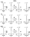
- FIGS. 11A to 11D respectively show spherical aberration, astigmatism, distortion (distortion aberration), and lateral chromatic aberration (chromatic aberration of magnification) at the wide-angle end of the projection zoom lens of Example 1.
- the figure is shown.
- (E) to (H) in the same figure show aberration diagrams of spherical aberration, astigmatism, distortion, and lateral chromatic aberration at the intermediate position of the projection zoom lens of Example 1, respectively.
- (I) to (L) in the same figure show aberration diagrams of spherical aberration, astigmatism, distortion, and lateral chromatic aberration at the telephoto end of the projection zoom lens of Example 1, respectively.
- the distortion is suppressed within about 2% in the entire zooming region. This is almost the same in the other Examples 2 to 10.
- the aberration diagrams in FIGS. 11A to 11L are based on the d-line, but in the spherical aberration diagram, the C-line (wavelength 656.3 nm) and the F-line (wavelength wavelength 486.1 nm). Are also shown, and the chromatic aberration diagram for magnification shows aberrations for the C-line and F-line.
- aberrations in the sagittal direction and the tangential direction are indicated by a solid line and a broken line, respectively.
- Example 1 The symbols, meanings, and description methods of the lens group arrangement diagram, table, and aberration diagram of Example 1 described above are basically the same for Examples 2 to 10 below, unless otherwise specified.
- the lens group arrangement diagram (FIG. 1) of Example 1 described above is at the wide-angle end, the intermediate position, and the telephoto end, and the aberration diagram is at the wide-angle end, the intermediate position, and the telephoto end. The same applies to Examples 2 to 10.
- FIG. 2 shows the arrangement of the lens groups at the wide-angle end and the telephoto end of the projection zoom lens according to the second embodiment, and at an intermediate position therebetween.
- the first lens group G1 includes a positive first lens L1, a negative second lens L2, a negative third lens L3, and a negative fourth lens L4, which are arranged in order from the enlargement side. It consists of four lenses.
- the second lens group G2 includes two lenses, a negative fifth lens L5 and a positive sixth lens L6, which are arranged in this order from the magnification side.
- the third lens group G3 includes two lenses, a positive seventh lens L7 and a negative eighth lens L8, which are arranged in order from the enlargement side, and an aperture stop St that is a variable stop.
- the fourth lens group G4 includes two lenses, a positive ninth lens L9 and a negative tenth lens L10, which are arranged in this order from the magnification side.
- the fifth lens group G5 includes four lenses, a negative eleventh lens L11, a negative twelfth lens L12, a positive thirteenth lens L13, and a positive fourteenth lens L14, which are arranged in order from the magnification side. It is composed of The sixth lens group G6 includes one positive fifteenth lens L15.
- the fifth lens L5 and the sixth lens L6 are cemented, and the twelfth lens L12 and the thirteenth lens L13 are also cemented.
- Table 3 shows basic lens data of the projection zoom lens of Example 2.
- Table 4 shows the specifications at the wide-angle end, the intermediate position, and the telephoto end when the zoom lens for projection according to the second embodiment is zoomed in the same manner as in Table 2.
- the display items and the display method in them are as described above.
- FIGS. 12A to 12L show aberration diagrams of the projection zoom lens of Example 2.
- FIG. 12A to 12L show aberration diagrams of the projection zoom lens of Example 2.
- FIG. 3 shows the arrangement of the lens groups at the wide-angle end and the telephoto end of the zoom lens for projection according to the third embodiment, and at an intermediate position therebetween.
- the first lens group G1 includes a positive first lens L1, a negative second lens L2, a negative third lens L3, and a negative fourth lens L4 arranged in order from the magnification side. It consists of four lenses.
- the second lens group G2 is composed of one positive fifth lens L5.
- the third lens group G3 includes two lenses, a positive sixth lens L6 and a negative seventh lens L7, which are arranged in order from the enlargement side, and an aperture stop St that is a variable stop.
- the fourth lens group G4 includes two lenses, a positive eighth lens L8 and a negative ninth lens L9, which are arranged in this order from the magnification side.
- the fifth lens group G5 includes a positive tenth lens L10, a negative eleventh lens L11, a negative twelfth lens L12, a positive thirteenth lens L13, and a positive tenth lens arranged in order from the enlargement side. It consists of five lenses of 14 lenses L14.
- the sixth lens group G6 includes one positive fifteenth lens L15.
- the twelfth lens L12 and the thirteenth lens L13 are cemented.
- the tenth lens L10 is formed of a thin resin layer bonded to the enlargement side lens surface of the eleventh lens L11, and constitutes a composite aspherical surface.
- Table 5 shows basic lens data of the projection zoom lens of Example 3.
- Table 6 shows the specifications at the wide-angle end, the intermediate position, and the telephoto end when the zoom lens for projection of Example 3 is zoomed in the same manner as Table 2.
- the display items and the display method in them are as described above.
- Example 3 since the enlargement side lens surface (surface of surface number 20) of the tenth lens L10 is an aspheric surface, Table 7 shows data relating to the aspheric surface.
- the aspheric data in Table 7 shows the surface number of the aspheric surface and the aspheric coefficient for each aspheric surface.
- the numerical value “E ⁇ n” (n: integer) of the aspheric data in Table 7 means “ ⁇ 10 ⁇ n ”.
- FIGS. 13A to 13L show aberration diagrams of the projection zoom lens of Example 3.
- FIG. 13A to 13L show aberration diagrams of the projection zoom lens of Example 3.
- FIG. 4 shows the arrangement of the lens groups at the wide-angle end and the telephoto end of the projection zoom lens according to the fourth embodiment, and at an intermediate position therebetween.
- the first lens group G1 includes a positive first lens L1, a negative second lens L2, a negative third lens L3, and a negative fourth lens L4 arranged in order from the enlargement side. It consists of four lenses.
- the second lens group G2 includes a negative fifth lens L5 and a positive sixth lens L6, which are arranged in order from the enlargement side.
- the third lens group G3 includes two lenses, a positive seventh lens L7 and a negative eighth lens L8, which are arranged in order from the enlargement side.
- the fourth lens group G4 includes an aperture stop St that is a variable stop, and a positive ninth lens L9, which are arranged in order from the enlargement side.
- the fifth lens group G5 includes a negative tenth lens L10, a positive eleventh lens L11, a negative twelfth lens L12, a positive thirteenth lens L13, and a positive tenth lens arranged in order from the magnification side. It consists of five lenses of 14 lenses L14.
- the sixth lens group G6 is composed of two lenses, a negative 15th lens L15 and a positive 16th lens L16, which are arranged in this order from the magnification side.
- the fifth lens L5 and the sixth lens L6 are cemented, the twelfth lens L12 and the thirteenth lens L13 are cemented, and the fifteenth lens L15 and the sixteenth lens L16 are also cemented.
- Table 8 shows basic lens data of the projection zoom lens of Example 4.
- Table 9 shows the specifications at the wide-angle end, the intermediate position, and the telephoto end when the zoom lens for projection of Example 4 is zoomed in the same manner as in Table 2.
- the display items and the display method in them are as described above.
- FIGS. 14A to 14L show aberration diagrams of the projection zoom lens of Example 4.
- FIG. 14A to 14L show aberration diagrams of the projection zoom lens of Example 4.
- FIG. 5 shows the arrangement of lens groups at the wide-angle end and the telephoto end of the zoom lens for projection according to the fifth embodiment, and at an intermediate position therebetween.
- the first lens group G1 includes a positive first lens L1, a negative second lens L2, a negative third lens L3, and a negative fourth lens L4, which are arranged in order from the enlargement side. It consists of four lenses.
- the second lens group G2 includes a negative fifth lens L5 and a positive sixth lens L6, which are arranged in order from the enlargement side.
- the third lens group G3 includes two lenses, a positive seventh lens L7 and a negative eighth lens L8, which are arranged in order from the enlargement side.
- the fourth lens group G4 includes an aperture stop St that is a variable stop, and a positive ninth lens L9, which are arranged in order from the enlargement side.
- the fifth lens group G5 includes a negative tenth lens L10, a positive eleventh lens L11, a negative twelfth lens L12, a positive thirteenth lens L13, and a positive tenth lens arranged in order from the magnification side. It consists of five lenses of 14 lenses L14.
- the sixth lens group G6 includes one positive fifteenth lens L15.
- the fifth lens L5 and the sixth lens 6 are cemented, and the twelfth lens L12 and the thirteenth lens L13 are also cemented.
- Table 10 shows basic lens data of the projection zoom lens of Example 5.
- Table 11 shows the specifications at the wide-angle end, the intermediate position, and the telephoto end when the zoom lens for projection of Example 5 is zoomed in the same manner as in Table 2.
- the display items and the display method in them are as described above.
- FIGS. 15A to 15L show aberration diagrams of the projection zoom lens of Example 5.
- FIG. 15A to 15L show aberration diagrams of the projection zoom lens of Example 5.
- FIG. 6 shows the arrangement of lens groups at the wide-angle end and the telephoto end of the zoom lens for projection according to the sixth embodiment, and the intermediate positions thereof.
- the first lens group G1 includes a positive first lens L1, a negative second lens L2, a negative third lens L3, and a negative fourth lens L4, which are arranged in order from the enlargement side. It consists of four lenses.
- the second lens group G2 includes a negative fifth lens L5 and a positive sixth lens L6, which are arranged in order from the enlargement side.
- the third lens group G3 includes two lenses, a positive seventh lens L7 and a negative eighth lens L8, which are arranged in order from the enlargement side.
- the fourth lens group G4 includes an aperture stop St that is a variable stop, and a positive ninth lens L9, which are arranged in order from the enlargement side.
- the fifth lens group G5 includes a negative tenth lens L10, a positive eleventh lens L11, a negative twelfth lens L12, a positive thirteenth lens L13, and a positive tenth lens arranged in order from the magnification side. It consists of five lenses of 14 lenses L14.
- the sixth lens group G6 includes one positive fifteenth lens L15.
- the fifth lens L5 and the sixth lens 6 are cemented, and the twelfth lens L12 and the thirteenth lens L13 are also cemented.
- Table 12 shows basic lens data of the projection zoom lens of Example 6.
- Table 13 shows the specifications at the wide-angle end, the intermediate position, and the telephoto end when the zoom lens for projection of Example 6 is zoomed in the same manner as in Table 2.
- the display items and the display method in them are as described above.
- FIGS. 16A to 16L show respective aberration diagrams of the projection zoom lens of Example 6.
- FIG. 7 shows the arrangement of the lens groups at the wide-angle end and the telephoto end of the projection zoom lens according to the seventh embodiment, and at an intermediate position therebetween.
- the projection zoom lens of Example 7 includes a first lens group G1 having a negative refractive power that is disposed closest to the enlargement side and fixed at the time of zooming, and a reduction after the first lens group G1.
- the configuration of the lens group described above is common to the seventh, eighth, and tenth embodiments.
- the first lens group G1 is composed of three lenses, a positive first lens L1, a negative second lens L2, and a negative third lens L3, which are arranged in order from the magnification side. ing.
- the second lens group G2 includes a negative fourth lens L4 and a positive fifth lens L5, which are arranged in order from the enlargement side.
- the third lens group G3 is composed of a positive sixth lens L6 and a negative seventh lens L7, which are arranged in order from the enlargement side.
- the fourth lens group G4 includes one positive eighth lens L8.
- the fifth lens group G5 includes an aperture stop St that is a variable stop, a negative ninth lens L9, a positive tenth lens L10, a negative eleventh lens L11, and a positive lens arranged in order from the enlargement side.
- the lens includes five lenses, a twelfth lens L12 and a positive thirteenth lens L13.
- the sixth lens group G6 includes one positive fourteenth lens L14.
- the fourth lens L4 and the fifth lens 5 are cemented, and the eleventh lens L11 and the twelfth lens L12 are also cemented.
- Table 14 shows basic lens data of the projection zoom lens of Example 7.
- Table 15 shows the specifications at the wide-angle end, the intermediate position, and the telephoto end when the zoom lens for projection of Example 7 is zoomed in the same manner as Table 2.
- FIGS. 17A to 17L show aberration diagrams of the projection zoom lens of Example 7.
- FIG. 8 shows the arrangement of the lens groups at the wide-angle end and the telephoto end of the zoom lens for projection according to the eighth embodiment and at an intermediate position therebetween.
- the first lens group G1 is composed of three lenses, a positive first lens L1, a negative second lens L2, and a negative third lens L3, which are arranged in order from the magnification side.
- the second lens group G2 includes a negative fourth lens L4 and a positive fifth lens L5, which are arranged in order from the enlargement side.
- the third lens group G3 is composed of a positive sixth lens L6 and a negative seventh lens L7, which are arranged in order from the enlargement side.
- the fourth lens group G4 includes one positive eighth lens L8.
- the fifth lens group G5 includes an aperture stop St that is a variable stop, a negative ninth lens L9, a positive tenth lens L10, a negative eleventh lens L11, and a positive lens arranged in order from the enlargement side.
- the lens includes five lenses, a twelfth lens L12 and a positive thirteenth lens L13.
- the sixth lens group G6 includes one positive fourteenth lens L14.
- the fourth lens L4 and the fifth lens 5 are cemented, and the eleventh lens L11 and the twelfth lens L12 are also cemented.
- Table 16 shows basic lens data of the projection zoom lens of Example 8.
- Table 17 shows the specifications at the wide-angle end, the intermediate position, and the telephoto end when the zoom lens for projection of Example 8 is zoomed in the same manner as Table 2.
- FIGS. 18A to 18L show aberration diagrams of the projection zoom lens of Example 8.
- FIG. 18A to 18L show aberration diagrams of the projection zoom lens of Example 8.
- FIG. 9 shows the arrangement of the lens groups at the wide-angle end and the telephoto end of the projection zoom lens according to the ninth embodiment, and at an intermediate position therebetween.
- the first lens group G1 includes a positive first lens L1, a negative second lens L2, a negative third lens L3, and a negative fourth lens L4, which are arranged in order from the enlargement side. It consists of four lenses.
- the second lens group G2 is composed of one positive fifth lens L5.
- the third lens group G3 includes a positive sixth lens L6 and an aperture stop St that is a variable stop, which are arranged in order from the enlargement side.
- the fourth lens group G4 includes a positive seventh lens L7 and a negative eighth lens L8, which are arranged in order from the enlargement side.
- the fifth lens group G5 includes a positive ninth lens L9, a negative tenth lens L10, a negative eleventh lens L11, a positive twelfth lens L12, and a positive first lens L9, which are arranged in order from the magnification side. It consists of five lenses, 13 lenses L13.
- the sixth lens group G6 includes one positive fourteenth lens L14.
- the seventh lens L7 and the eighth lens 8 are cemented, the ninth lens L9 and the tenth lens 10 are cemented, and the eleventh lens L11 and the twelfth lens L12 are also cemented.
- Table 18 shows basic lens data of the projection zoom lens of Example 9.
- Table 19 shows the specifications at the wide-angle end, the intermediate position, and the telephoto end when the zoom lens for projection of Example 9 is zoomed in the same manner as in Table 2.
- FIGS. 19A to 19L show aberration diagrams of the projection zoom lens of Example 9, respectively.
- FIG. 10 shows the arrangement of the lens groups at the wide-angle end and the telephoto end of the zoom lens for projection according to the tenth embodiment and at an intermediate position therebetween.
- the first lens group G1 is composed of three lenses, a positive first lens L1, a negative second lens L2, and a negative third lens L3, which are arranged in order from the magnification side.
- the second lens group G2 includes two lenses, a negative fourth lens L4 and a positive fifth lens L5, which are arranged in order from the magnification side.
- the third lens group G3 includes two lenses, a positive sixth lens L6 and a negative seventh lens L7, which are arranged in order from the enlargement side.
- the fourth lens group G4 includes one positive eighth lens L8.
- This aperture stop St is a movable aperture that moves as described above and makes the numerical aperture of the zoom lens constant in the entire zooming region.
- This aperture stop St has a constant aperture diameter, but may be a variable aperture that changes the aperture diameter in order to keep the numerical aperture of the zoom lens constant as described above.
- the aperture stop it is not always necessary that the aperture stop has the functions of both the movable stop and the variable stop, and only one of the functions may be provided, and further, neither function is provided. An aperture stop may be applied.
- the fifth lens group G5 includes a negative ninth lens L9, a positive tenth lens L10, a negative eleventh lens L11, a positive twelfth lens L12, and a positive first lens arranged in order from the magnification side. It consists of five lenses, 13 lenses L13.
- the sixth lens group G6 includes one positive fourteenth lens L14.
- the fourth lens L4 and the fifth lens 5 are cemented, and the eleventh lens L11 and the twelfth lens L12 are also cemented.
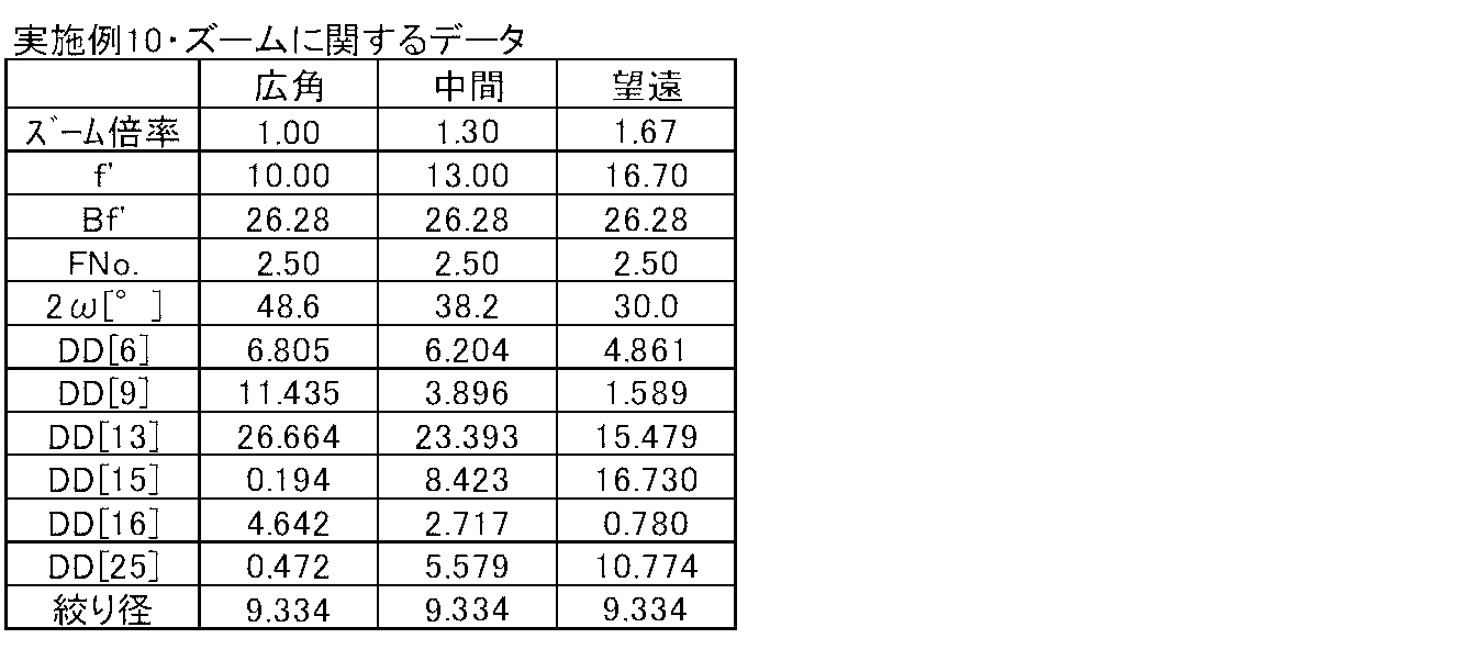
- Table 20 shows basic lens data of the projection zoom lens of Example 10.
- Table 21 shows the specifications at the wide-angle end, the intermediate position, and the telephoto end when the zoom lens for projection according to the tenth embodiment performs zooming similarly to Table 2.
- FIGS. 20A to 20L show aberration diagrams of the projection zoom lens of Example 10, respectively.
- the projection display device of the present invention is not limited to the above-described configuration.
- the light valve used and the optical member used for light beam separation or light beam synthesis are not limited to the above-described configuration. Various modifications can be made.
Landscapes
- Physics & Mathematics (AREA)
- General Physics & Mathematics (AREA)
- Optics & Photonics (AREA)
- Lenses (AREA)
- Projection Apparatus (AREA)
- Nonlinear Science (AREA)
Abstract
Description
実質的に、拡大側から順に配された、負の屈折力を有する第1レンズ群、変倍の際に光軸に沿って移動する正の屈折力を有する第2レンズ群、変倍の際に光軸に沿って移動する正の屈折力を有する第3レンズ群、変倍の際に光軸に沿って移動する正の屈折力を有する第4レンズ群、変倍の際に光軸に沿って移動する第5レンズ群、および正の屈折力を有する第6レンズ群からなる投写用ズームレンズにおいて、
縮小側がテレセントリックとなるように構成され、
該ズームレンズの開口数が全変倍領域において一定となるように構成され、
前記第4レンズ群の広角端から望遠端までの変倍時移動量が全レンズ群中最大であり、
そして第2、3、4および5レンズ群の、広角端から望遠端までの変倍時移動量の絶対値をそれぞれm2、m3、m4、およびm5とし、広角端における全系の焦点距離をfwとして下記の条件式(1)および(2)
1.9<m4/fw… (1)
0.7<(m3+m4)/(m2+m3+m4+m5)… (2)
を満たしていることを特徴とするものである。
実質的に、拡大側から順に配された、負の屈折力を有する第1レンズ群、変倍の際に光軸に沿って移動する正の屈折力を有する第2レンズ群、変倍の際に光軸に沿って移動する正の屈折力を有する第3レンズ群、変倍の際に光軸に沿って移動する正の屈折力を有する第4レンズ群、変倍の際に光軸に沿って移動する第5レンズ群、および正の屈折力を有する第6レンズ群からなる投写用ズームレンズにおいて、
前記第5レンズ群が負の屈折力を有するものとされ、
縮小側がテレセントリックとなるように構成され、
該ズームレンズの開口数が全変倍領域において一定となるように構成され、
前記第4レンズ群の広角端から望遠端までの変倍時移動量が全レンズ群中最大であり、
そして、第4レンズ群の、広角端から望遠端までの変倍時移動量の絶対値をm4、広角端における全系の焦点距離をfwとして、下記条件式(1)
1.9<m4/fw… (1)
を満たしていることを特徴とするものである。
0.7<(m3+m4)/(m2+m3+m4+m5)… (2)
が満たされていることが望ましい。
開口絞りが第3レンズ群の縮小側かつ第5レンズ群の拡大側に配置され、
そして、第4レンズ群の焦点距離をf4、広角端における全系の焦点距離をfwとして下記条件式(3)
3.0<f4/fw<5.5… (3)
が満たされていることが望ましい。
3.5<f4/fw<5.0… (3’)
が満たされていることがより望ましい。
2.5<Bf/Imφ… (4)
L/Imφ<12… (5)
が満たされていることが望ましい。
8<L/Imφ<11… (5’)
が満たされていることがより望ましい。
第4レンズ群が正の屈折力を有するレンズを含み、
そして、この正の屈折力を有するレンズの媒質のアッベ数をνpとして、下記条件式(6)
60<νp… (6)
が満たされていることが望ましい。
70<νp… (6’)
が満たされていることがより望ましく、さらには下式(6”)、
80<νp… (6”)
が満たされていることがより一層望ましい。
また、本発明による第1あるいは第2の投写用ズームレンズにおいて、特に、上述のように開口絞りが第3レンズ群の縮小側かつ第5レンズ群の拡大側に配置された上で条件式(3)が満たされている場合は、第5レンズ群が拡大側から順に、負の屈折力を有するレンズ、正の屈折力を有するレンズ、負の屈折力を有するレンズの並びを含むことが望ましい。
1.9<m4/fw… (1)
0.7<(m3+m4)/(m2+m3+m4+m5)… (2)
が満たされる程に大きく取っているので、高変倍比を確保できるものとなる。
1.9<m4/fw… (1)
が満たされる程に大きく取っているので、高変倍比を確保できるものとなる。
0.7<(m3+m4)/(m2+m3+m4+m5)… (2)
が満たされる程に大きく取っている場合は、より高変倍比を確保できるものとなる。
その上で本発明による第1、第2の投写用ズームレンズでは、第3レンズ群と第4レンズ群、とりわけ第4レンズ群に変倍機能の多くを振り分けるように構成したので、第2レンズ群および第5レンズ群に収差補正機能を多く分担させることができる。そこで、長バックフォーカスとしても収差補正を良好に行うことができるので、長いバックフォーカスと高変倍比を両立させることが可能になる。
3.0<f4/fw<5.5… (3)
が満たされている場合は、球面収差を小さく抑え、また小型化することが可能になる。すなわちf4/fwの値が3.0以下になると球面収差が増大し、その値が5.5以上になると、レンズ径が大きくなってズームレンズが大型化しやすいが、条件式(3)が満たされていれば、そのような問題を回避して、球面収差を小さく抑え、また小型化することが可能になる。
3.5<f4/fw<5.0… (3’)
が満たされている場合は、より顕著なものとなる。
2.5<Bf/Imφ… (4)
L/Imφ<12… (5)
が満たされていれば、前述したプリズム等を挿入するためのレンズバックのスペースを容易に確保でき、そしてズームレンズの小型化を実現できる。
8<L/Imφ<11… (5’)
が満たされている場合は、より顕著なものとなる。そしてこの場合は、色収差も小さく抑えることが可能になる。すなわち、L/Imφの値が8以下である場合は、色収差が増大しやすいが、L/Imφの値が8を上回っていれば、そのような問題を回避して、色収差を小さく抑えることが可能になる。
60<νp… (6)
が満たされていれば、軸上色収差を小さく抑えることが可能になる。
70<νp… (6’)
が満たされている場合は、より顕著なものとなり、さらに下式(6”)、
80<νp… (6”)
が満たされている場合は、より一層顕著なものとなる。
1.9<m4/fw… (1)
0.7<(m3+m4)/(m2+m3+m4+m5)… (2)
が満たされている。それにより本実施形態の投写用ズームレンズは、高変倍比を確保できるものとなっている。
3.0<f4/fw<5.5… (3)
が満たされている。それにより本実施形態の投写用ズームレンズは、球面収差を小さく抑え、また小型化することが可能になる。その理由は、先に詳しく説明した通りである。
2.5<Bf/Imφ… (4)
L/Imφ<12… (5)
が満たされている。それにより本実施形態の投写用ズームレンズでは、前述したプリズム等を挿入するためのレンズバックのスペースを容易に確保でき、そして小型化を実現できる。その理由は、先に詳しく説明した通りである。
60<νp… (6)
が満たされている。なお各レンズのアッベ数については、後述する表1に示してある。
図1に、実施例1の投写用ズームレンズの広角端および望遠端、並びにそれらの中間位置におけるレンズ群の配置を示す。なお、図1についての詳細な説明は先に説明した通りであるので、ここでは特に必要の無い限り重複した説明は省略する。
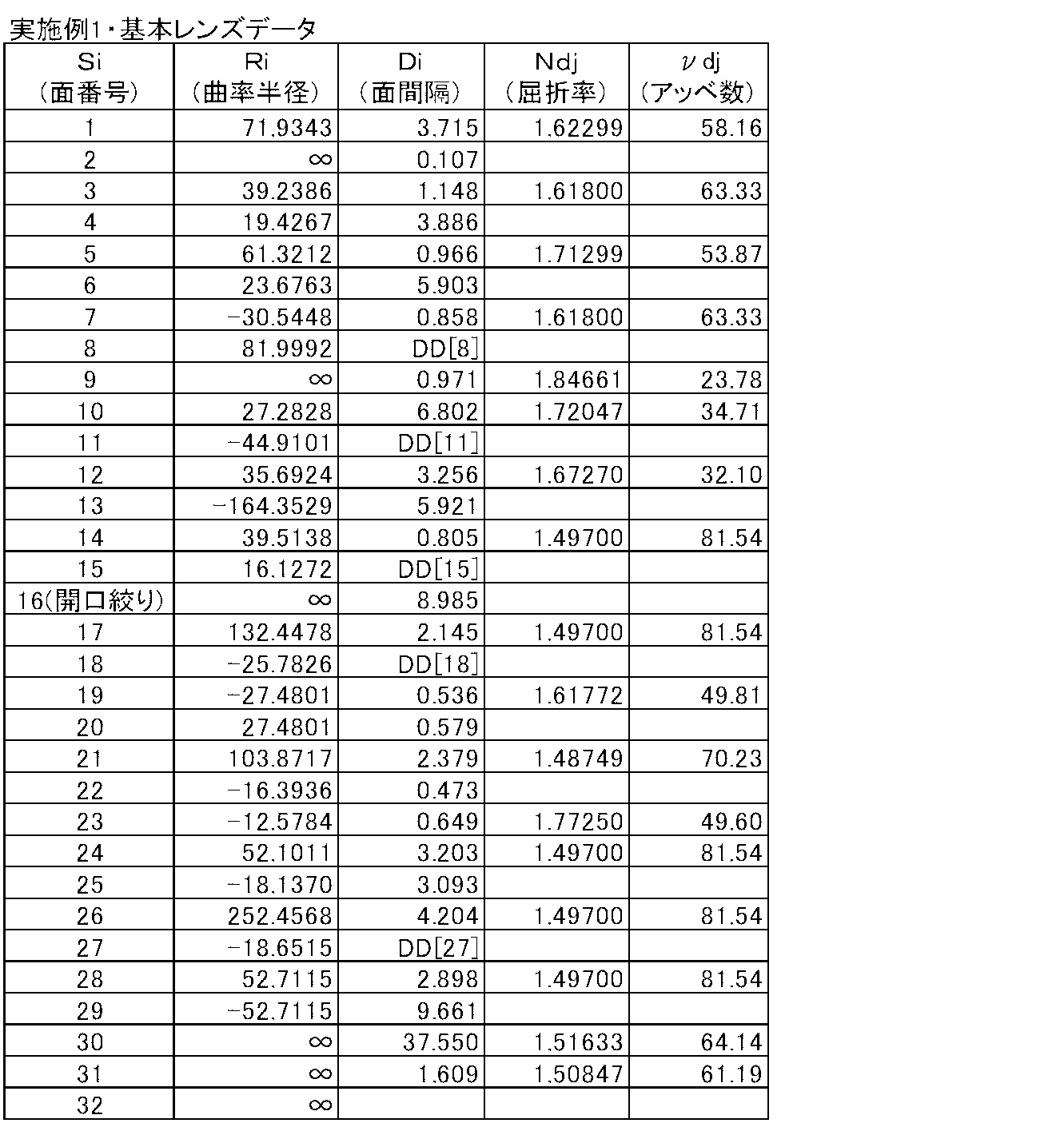
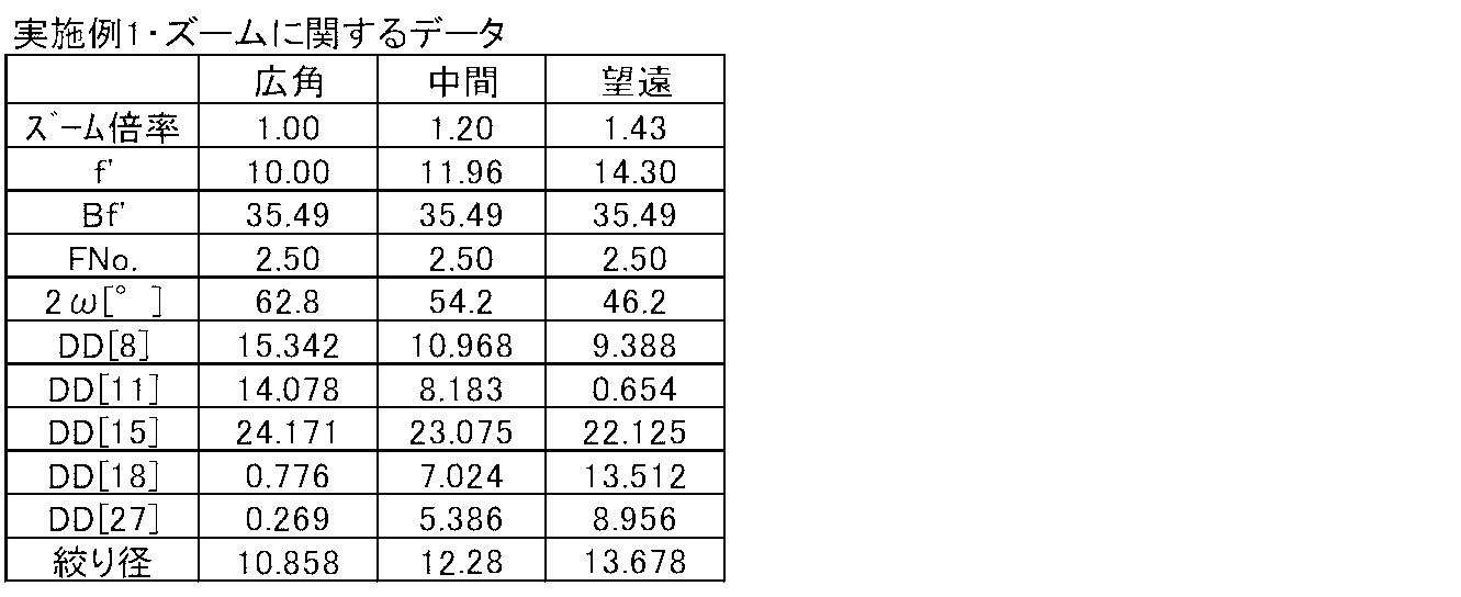
図2に、実施例2の投写用ズームレンズの広角端および望遠端、並びにそれらの中間位置おけるレンズ群の配置を示す。この実施例2において第1レンズ群G1は、拡大側から順に配置された、正の第1レンズL1と、負の第2レンズL2と、負の第3レンズL3と、負の第4レンズL4の4枚のレンズから構成されている。また第2レンズ群G2は、拡大側から順に配置された、負の第5レンズL5と、正の第6レンズL6の2枚のレンズから構成されている。

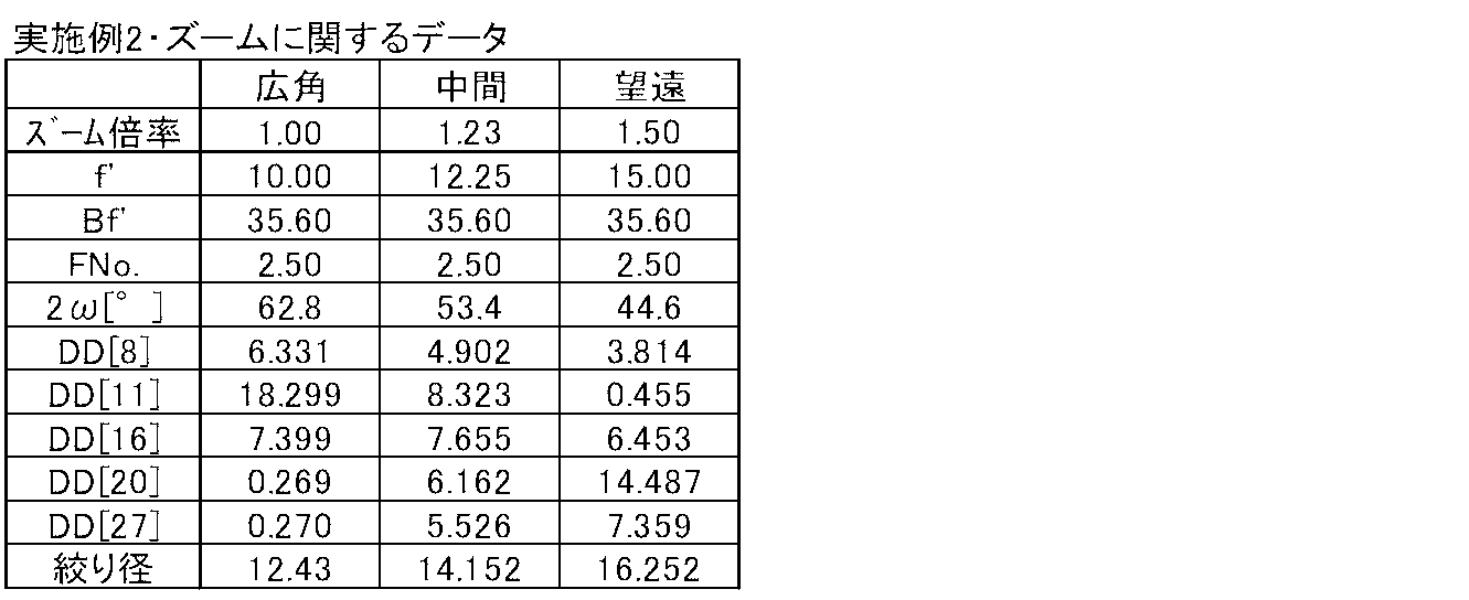
図3に、実施例3の投写用ズームレンズの広角端および望遠端、並びにそれらの中間位置におけるレンズ群の配置を示す。この実施例3において第1レンズ群G1は、拡大側から順に配置された、正の第1レンズL1と、負の第2レンズL2と、負の第3レンズL3と、負の第4レンズL4の4枚のレンズから構成されている。また第2レンズ群G2は1枚の正の第5レンズL5から構成されている。
ただし、
Zd:非球面深さ(高さhの非球面上の点から、非球面頂点が接する光軸に垂直な平面に下ろした垂線の長さ)
h:高さ(光軸からのレンズ面までの距離)
C:近軸曲率半径の逆数
KA、Am:非球面係数(m=3、4、5、…16)


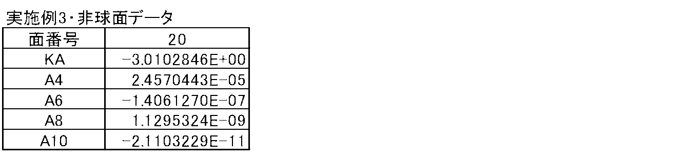
図4に、実施例4の投写用ズームレンズの広角端および望遠端、並びにそれらの中間位置におけるレンズ群の配置を示す。この実施例4において第1レンズ群G1は、拡大側から順に配置された、正の第1レンズL1と、負の第2レンズL2と、負の第3レンズL3と、負の第4レンズL4の4枚のレンズから構成されている。また第2レンズ群G2は、拡大側から順に配置された、負の第5レンズL5と、正の第6レンズL6とから構成されている。
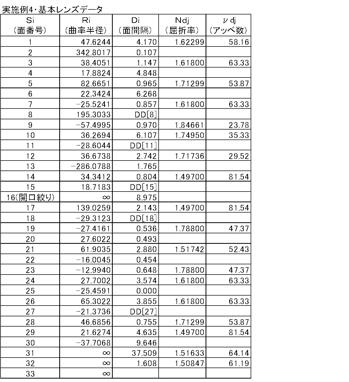

図5に、実施例5の投写用ズームレンズの広角端および望遠端、並びにそれらの中間位置におけるレンズ群の配置を示す。この実施例5において第1レンズ群G1は、拡大側から順に配置された、正の第1レンズL1と、負の第2レンズL2と、負の第3レンズL3と、負の第4レンズL4の4枚のレンズから構成されている。また第2レンズ群G2は、拡大側から順に配置された、負の第5レンズL5と、正の第6レンズL6とから構成されている。
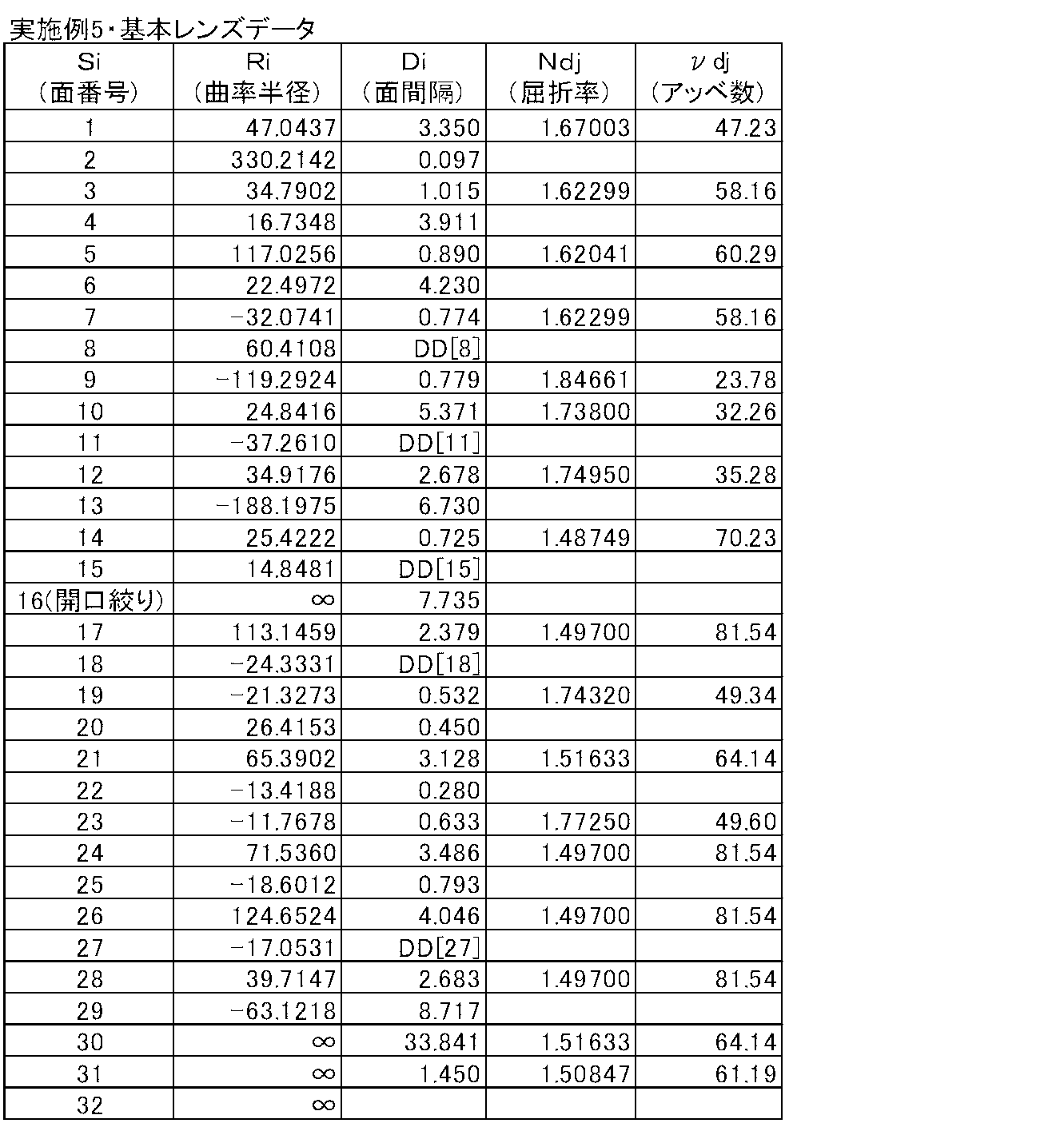
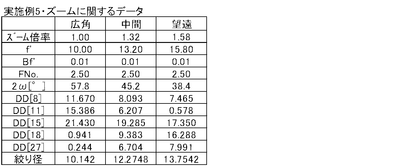
図6に、実施例6の投写用ズームレンズの広角端および望遠端、並びにそれらの中間位置におけるレンズ群の配置を示す。この実施例6において第1レンズ群G1は、拡大側から順に配置された、正の第1レンズL1と、負の第2レンズL2と、負の第3レンズL3と、負の第4レンズL4の4枚のレンズから構成されている。また第2レンズ群G2は、拡大側から順に配置された、負の第5レンズL5と、正の第6レンズL6とから構成されている。


図7に、実施例7の投写用ズームレンズの広角端および望遠端、並びにそれらの中間位置におけるレンズ群の配置を示す。
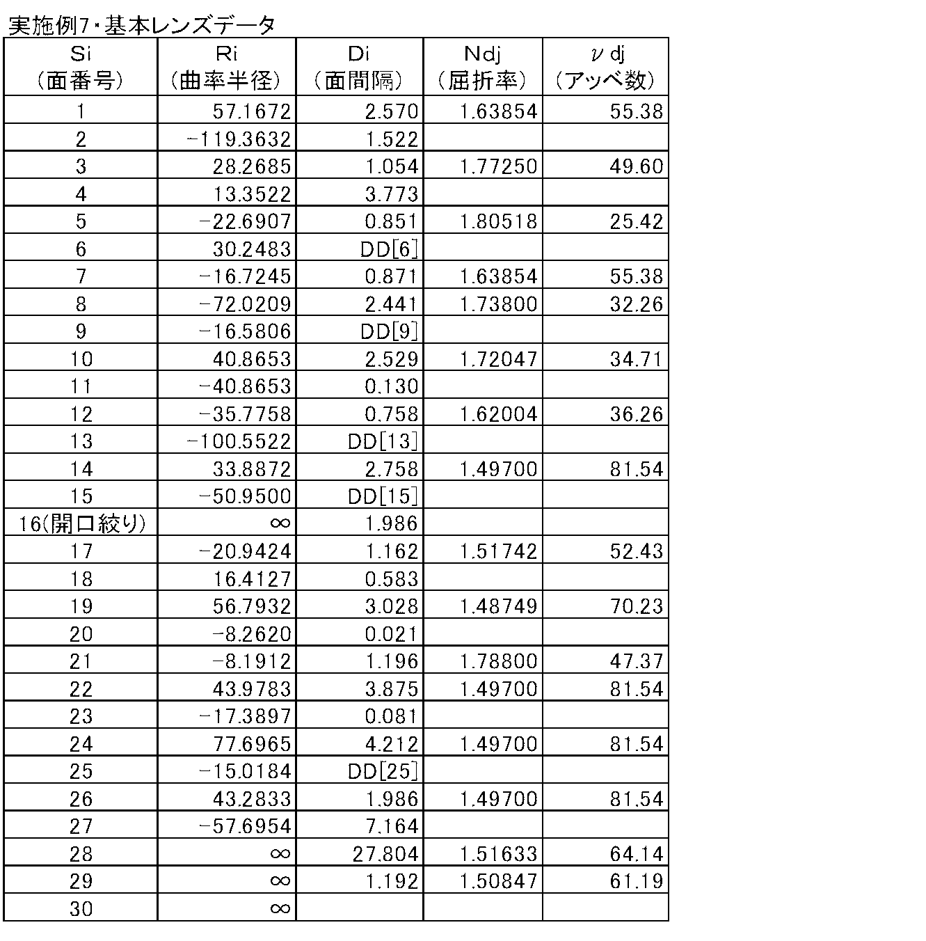

図8に、実施例8の投写用ズームレンズの広角端および望遠端、並びにそれらの中間位置におけるレンズ群の配置を示す。この実施例8において第1レンズ群G1は、拡大側から順に配置された、正の第1レンズL1と、負の第2レンズL2と、負の第3レンズL3の3枚のレンズから構成されている。また第2レンズ群G2は、拡大側から順に配置された、負の第4レンズL4と、正の第5レンズL5とから構成されている。


図9に、実施例9の投写用ズームレンズの広角端および望遠端、並びにそれらの中間位置におけるレンズ群の配置を示す。


図10に、実施例10の投写用ズームレンズの広角端および望遠端、並びにそれらの中間位置におけるレンズ群の配置を示す。


Claims (17)
- 実質的に、拡大側から順に配された、負の屈折力を有する第1レンズ群、変倍の際に光軸に沿って移動する正の屈折力を有する第2レンズ群、変倍の際に光軸に沿って移動する正の屈折力を有する第3レンズ群、変倍の際に光軸に沿って移動する正の屈折力を有する第4レンズ群、変倍の際に光軸に沿って移動する第5レンズ群、および正の屈折力を有する第6レンズ群からなる投写用ズームレンズにおいて、
縮小側がテレセントリックとなるように構成され、
該ズームレンズの開口数が全変倍領域において一定となるように構成され、
前記第4レンズ群の広角端から望遠端までの変倍時移動量が全レンズ群中最大であり、
以下の条件式(1)および(2)を満たすことを特徴とする投写用ズームレンズ。
1.9<m4/fw… (1)
0.7<(m3+m4)/(m2+m3+m4+m5)… (2)
ただし、
m2:第2レンズ群の、広角端から望遠端までの変倍時移動量の絶対値
m3:第3レンズ群の、広角端から望遠端までの変倍時移動量の絶対値
m4:第4レンズ群の、広角端から望遠端までの変倍時移動量の絶対値
m5:第5レンズ群の、広角端から望遠端までの変倍時移動量の絶対値
fw:広角端における全系の焦点距離 - 実質的に、拡大側から順に配された、負の屈折力を有する第1レンズ群、変倍の際に光軸に沿って移動する正の屈折力を有する第2レンズ群、変倍の際に光軸に沿って移動する正の屈折力を有する第3レンズ群、変倍の際に光軸に沿って移動する正の屈折力を有する第4レンズ群、変倍の際に光軸に沿って移動する第5レンズ群、および正の屈折力を有する第6レンズ群からなる投写用ズームレンズにおいて、
前記第5レンズ群が負の屈折力を有するものとされ、
縮小側がテレセントリックとなるように構成され、
該ズームレンズの開口数が全変倍領域において一定となるように構成され、
前記第4レンズ群の広角端から望遠端までの変倍時移動量が全レンズ群中最大であり、
以下の条件式(1)を満たすことを特徴とする投写用ズームレンズ。
1.9<m4/fw… (1)
ただし、
m4:第4レンズ群の、広角端から望遠端までの変倍時移動量の絶対値
fw:広角端における全系の焦点距離 - 以下の条件式(2)を満たすことを特徴とする請求項2記載の投写用ズームレンズ。
0.7<(m3+m4)/(m2+m3+m4+m5)… (2)
ただし、
m2:第2レンズ群の、広角端から望遠端までの変倍時移動量の絶対値
m3:第3レンズ群の、広角端から望遠端までの変倍時移動量の絶対値
m4:第4レンズ群の、広角端から望遠端までの変倍時移動量の絶対値
m5:第5レンズ群の、広角端から望遠端までの変倍時移動量の絶対値 - 開口絞りが第3レンズ群の縮小側かつ第5レンズ群の拡大側に配置され、
以下の条件式(3)を満たすことを特徴とする請求項1から3いずれか1項記載の投写用ズームレンズ。
3.0<f4/fw<5.5… (3)
ただし、
f4:第4レンズ群の焦点距離
fw:広角端における全系の焦点距離 - 以下の条件式(3’)を満たすことを特徴とする請求項4記載の投写用ズームレンズ。
3.5<f4/fw<5.0… (3’) - 前記開口絞りが、変倍時に開口径が変化する可変絞りであることを特徴とする請求項4記載の投写用ズームレンズ。
- 前記開口絞りが、変倍時に他のレンズから独立して光軸方向に移動するものであることを特徴とする請求項4記載の投写用ズームレンズ。
- 前記第3レンズ群から第5レンズ群までのレンズ群が、広角端から望遠端への変倍時に拡大側へ単調に移動するものであることを特徴とする請求項4記載の投写用ズームレンズ。
- 以下の条件式(4)および(5)を満たすことを特徴とする請求項4記載の投写用ズームレンズ。
2.5<Bf/Imφ… (4)
L/Imφ<12… (5)
ただし、
Bf:広角端における全系の縮小側のバックフォーカス(空気換算距離)
Imφ:縮小側における最大有効像円直径
L:投写距離無限遠時の最も拡大側のレンズ面から最も縮小側のレンズ面までの光軸上の距離 - 以下の条件式(5’)を満たすことを特徴とする請求項9記載の投写用ズームレンズ。
8<L/Imφ<11… (5’) - 前記第2レンズ群が、負の屈折力を有するレンズを含むことを特徴とする請求項4記載の投写用ズームレンズ。
- 前記第3レンズ群が、負の屈折力を有するレンズを含むことを特徴とする請求項4記載の投写用ズームレンズ。
- 前記第4レンズ群が、正の屈折力を有するレンズを含み、
以下の条件式(6)を満たすことを特徴とする請求項4記載の投写用ズームレンズ。
60<νp… (6)
ただし、
νp:第4レンズ群中の前記正の屈折力を有するレンズの媒質のアッベ数 - 以下の条件式(6’)を満たすことを特徴とする請求項13記載の投写用ズームレンズ。
70<νp… (6’) - 以下の条件式(6”)を満たすことを特徴とする請求項13記載の投写用ズームレンズ。
80<νp… (6”) - 前記第5レンズ群が拡大側から順に、負の屈折力を有するレンズ、正の屈折力を有するレンズ、負の屈折力を有するレンズの並びを含むことを特徴とする請求項4記載の投写用ズームレンズ。
- 光源と、該光源からの光が入射するライトバルブと、該ライトバルブにより光変調された光による光学像をスクリーン上に投写する請求項1から3いずれか1項記載の投写用ズームレンズとを備えたことを特徴とする投写型表示装置。
Priority Applications (3)
| Application Number | Priority Date | Filing Date | Title |
|---|---|---|---|
| JP2014546862A JP5777191B2 (ja) | 2012-11-19 | 2013-11-11 | 投写用ズームレンズおよび投写型表示装置 |
| CN201390000896.2U CN204666944U (zh) | 2012-11-19 | 2013-11-11 | 投影用变焦透镜以及投影型显示装置 |
| US14/695,479 US9405108B2 (en) | 2012-11-19 | 2015-04-24 | Projection zoom lens and projection type display device |
Applications Claiming Priority (2)
| Application Number | Priority Date | Filing Date | Title |
|---|---|---|---|
| JP2012-253317 | 2012-11-19 | ||
| JP2012253317 | 2012-11-19 |
Related Child Applications (1)
| Application Number | Title | Priority Date | Filing Date |
|---|---|---|---|
| US14/695,479 Continuation US9405108B2 (en) | 2012-11-19 | 2015-04-24 | Projection zoom lens and projection type display device |
Publications (1)
| Publication Number | Publication Date |
|---|---|
| WO2014076925A1 true WO2014076925A1 (ja) | 2014-05-22 |
Family
ID=50730859
Family Applications (1)
| Application Number | Title | Priority Date | Filing Date |
|---|---|---|---|
| PCT/JP2013/006615 Ceased WO2014076925A1 (ja) | 2012-11-19 | 2013-11-11 | 投写用ズームレンズおよび投写型表示装置 |
Country Status (4)
| Country | Link |
|---|---|
| US (1) | US9405108B2 (ja) |
| JP (1) | JP5777191B2 (ja) |
| CN (1) | CN204666944U (ja) |
| WO (1) | WO2014076925A1 (ja) |
Cited By (1)
| Publication number | Priority date | Publication date | Assignee | Title |
|---|---|---|---|---|
| WO2018150982A1 (ja) * | 2017-02-17 | 2018-08-23 | 富士フイルム株式会社 | 投写用ズームレンズおよび投写型表示装置 |
Families Citing this family (4)
| Publication number | Priority date | Publication date | Assignee | Title |
|---|---|---|---|---|
| CN204925499U (zh) * | 2012-11-19 | 2015-12-30 | 富士胶片株式会社 | 投影用变焦透镜以及投影型显示装置 |
| CN107765412B (zh) * | 2017-11-14 | 2019-11-08 | 四川长虹电器股份有限公司 | 一种变焦投影镜头 |
| CN109884779B (zh) * | 2019-03-15 | 2023-10-27 | 广东奥普特科技股份有限公司 | 一种低畸变镜头 |
| KR20250143014A (ko) * | 2024-03-21 | 2025-09-30 | 엘지이노텍 주식회사 | 광학계 및 카메라 모듈 |
Citations (5)
| Publication number | Priority date | Publication date | Assignee | Title |
|---|---|---|---|---|
| JP2005292260A (ja) * | 2004-03-31 | 2005-10-20 | Fujinon Corp | ズームレンズおよびこれを用いた投写型表示装置 |
| JP2007206420A (ja) * | 2006-02-02 | 2007-08-16 | Canon Inc | ズームレンズ及びそれを有する画像投射装置 |
| JP2007256424A (ja) * | 2006-03-22 | 2007-10-04 | Fujinon Corp | 投写用ズームレンズおよび投写型表示装置 |
| JP2008046259A (ja) * | 2006-08-11 | 2008-02-28 | Fujinon Corp | 投写型ズームレンズおよび投写型表示装置 |
| JP2008242402A (ja) * | 2007-03-29 | 2008-10-09 | Canon Inc | 画像投射光学系及び画像投射装置 |
Family Cites Families (4)
| Publication number | Priority date | Publication date | Assignee | Title |
|---|---|---|---|---|
| JP2005106948A (ja) | 2003-09-29 | 2005-04-21 | Canon Inc | 投射光学系及び画像投射装置 |
| JP2006184723A (ja) | 2004-12-28 | 2006-07-13 | Canon Inc | ズームレンズおよび光学機器 |
| JP5009758B2 (ja) | 2007-11-26 | 2012-08-22 | 富士フイルム株式会社 | 投影用ズームレンズおよび投写型表示装置 |
| JP5545142B2 (ja) | 2010-09-10 | 2014-07-09 | コニカミノルタ株式会社 | 変倍機能を有する投影レンズ |
-
2013
- 2013-11-11 JP JP2014546862A patent/JP5777191B2/ja not_active Expired - Fee Related
- 2013-11-11 CN CN201390000896.2U patent/CN204666944U/zh not_active Expired - Lifetime
- 2013-11-11 WO PCT/JP2013/006615 patent/WO2014076925A1/ja not_active Ceased
-
2015
- 2015-04-24 US US14/695,479 patent/US9405108B2/en active Active
Patent Citations (5)
| Publication number | Priority date | Publication date | Assignee | Title |
|---|---|---|---|---|
| JP2005292260A (ja) * | 2004-03-31 | 2005-10-20 | Fujinon Corp | ズームレンズおよびこれを用いた投写型表示装置 |
| JP2007206420A (ja) * | 2006-02-02 | 2007-08-16 | Canon Inc | ズームレンズ及びそれを有する画像投射装置 |
| JP2007256424A (ja) * | 2006-03-22 | 2007-10-04 | Fujinon Corp | 投写用ズームレンズおよび投写型表示装置 |
| JP2008046259A (ja) * | 2006-08-11 | 2008-02-28 | Fujinon Corp | 投写型ズームレンズおよび投写型表示装置 |
| JP2008242402A (ja) * | 2007-03-29 | 2008-10-09 | Canon Inc | 画像投射光学系及び画像投射装置 |
Cited By (1)
| Publication number | Priority date | Publication date | Assignee | Title |
|---|---|---|---|---|
| WO2018150982A1 (ja) * | 2017-02-17 | 2018-08-23 | 富士フイルム株式会社 | 投写用ズームレンズおよび投写型表示装置 |
Also Published As
| Publication number | Publication date |
|---|---|
| US9405108B2 (en) | 2016-08-02 |
| US20150226947A1 (en) | 2015-08-13 |
| JP5777191B2 (ja) | 2015-09-09 |
| JPWO2014076925A1 (ja) | 2017-01-05 |
| CN204666944U (zh) | 2015-09-23 |
Similar Documents
| Publication | Publication Date | Title |
|---|---|---|
| JP5766889B2 (ja) | 投写用ズームレンズおよび投写型表示装置 | |
| JP5766798B2 (ja) | 投写用変倍光学系および投写型表示装置 | |
| JP5781705B2 (ja) | 投写用ズームレンズおよび投写型表示装置 | |
| CN204925499U (zh) | 投影用变焦透镜以及投影型显示装置 | |
| JP5603301B2 (ja) | 投写用変倍光学系および投写型表示装置 | |
| CN204903851U (zh) | 投影用变焦透镜以及投影型显示装置 | |
| CN105824109B (zh) | 投影光学系统以及投影型图像显示装置 | |
| CN205027961U (zh) | 投影用变焦透镜和投影型显示装置 | |
| US20140226219A1 (en) | Projection zoom lens and projection type display device | |
| WO2013171995A1 (ja) | 投写用変倍光学系および投写型表示装置 | |
| WO2013057909A1 (ja) | 投写用ズームレンズおよび投写型表示装置 | |
| WO2013157237A1 (ja) | 投写用レンズおよび投写型表示装置 | |
| CN204065540U (zh) | 投影用光学系统和投影型显示装置 | |
| WO2013076931A1 (ja) | 投写用ズームレンズおよび投写型表示装置 | |
| JP5777182B2 (ja) | 投写用変倍光学系および投写型表示装置 | |
| JP5781704B2 (ja) | 投写用ズームレンズおよび投写型表示装置 | |
| WO2012160786A1 (ja) | 投写用変倍光学系および投写型表示装置 | |
| JP5777191B2 (ja) | 投写用ズームレンズおよび投写型表示装置 | |
| CN206532030U (zh) | 投影用变焦透镜及投影型显示装置 | |
| JP2013007881A (ja) | 投写用変倍光学系および投写型表示装置 | |
| WO2013057910A1 (ja) | 投写用ズームレンズおよび投写型表示装置 | |
| WO2013136688A1 (ja) | 投写用ズームレンズおよび投写型表示装置 | |
| JP5611901B2 (ja) | 投写用変倍光学系および投写型表示装置 | |
| JP2013019986A (ja) | 投写用変倍光学系および投写型表示装置 | |
| JP2013019985A (ja) | 投写用変倍光学系および投写型表示装置 |
Legal Events
| Date | Code | Title | Description |
|---|---|---|---|
| WWE | Wipo information: entry into national phase |
Ref document number: 201390000896.2 Country of ref document: CN |
|
| 121 | Ep: the epo has been informed by wipo that ep was designated in this application |
Ref document number: 13854527 Country of ref document: EP Kind code of ref document: A1 |
|
| DPE1 | Request for preliminary examination filed after expiration of 19th month from priority date (pct application filed from 20040101) | ||
| ENP | Entry into the national phase |
Ref document number: 2014546862 Country of ref document: JP Kind code of ref document: A |
|
| NENP | Non-entry into the national phase |
Ref country code: DE |
|
| 122 | Ep: pct application non-entry in european phase |
Ref document number: 13854527 Country of ref document: EP Kind code of ref document: A1 |