WO2014073602A1 - Press molding method - Google Patents
Press molding method Download PDFInfo
- Publication number
- WO2014073602A1 WO2014073602A1 PCT/JP2013/080101 JP2013080101W WO2014073602A1 WO 2014073602 A1 WO2014073602 A1 WO 2014073602A1 JP 2013080101 W JP2013080101 W JP 2013080101W WO 2014073602 A1 WO2014073602 A1 WO 2014073602A1
- Authority
- WO
- WIPO (PCT)
- Prior art keywords
- die
- punch
- workpiece
- press molding
- central axis
- Prior art date
Links
- 238000000034 method Methods 0.000 title claims description 54
- 238000000465 moulding Methods 0.000 title claims description 37
- 230000008719 thickening Effects 0.000 claims abstract description 16
- 238000003825 pressing Methods 0.000 claims abstract description 4
- 230000002093 peripheral effect Effects 0.000 claims description 8
- 238000011946 reduction process Methods 0.000 claims description 4
- 238000007723 die pressing method Methods 0.000 claims description 2
- 230000006835 compression Effects 0.000 abstract 4
- 238000007906 compression Methods 0.000 abstract 4
- 230000004048 modification Effects 0.000 description 9
- 238000012986 modification Methods 0.000 description 9
- 238000010586 diagram Methods 0.000 description 5
- 238000013459 approach Methods 0.000 description 3
- 230000005540 biological transmission Effects 0.000 description 3
- 238000004519 manufacturing process Methods 0.000 description 2
- 238000005461 lubrication Methods 0.000 description 1
- 238000003672 processing method Methods 0.000 description 1
- 238000003466 welding Methods 0.000 description 1
Images


Classifications
-
- B—PERFORMING OPERATIONS; TRANSPORTING
- B21—MECHANICAL METAL-WORKING WITHOUT ESSENTIALLY REMOVING MATERIAL; PUNCHING METAL
- B21D—WORKING OR PROCESSING OF SHEET METAL OR METAL TUBES, RODS OR PROFILES WITHOUT ESSENTIALLY REMOVING MATERIAL; PUNCHING METAL
- B21D51/00—Making hollow objects
- B21D51/16—Making hollow objects characterised by the use of the objects
- B21D51/38—Making inlet or outlet arrangements of cans, tins, baths, bottles, or other vessels; Making can ends; Making closures
- B21D51/44—Making closures, e.g. caps
- B21D51/46—Placing sealings or sealing material
-
- B—PERFORMING OPERATIONS; TRANSPORTING
- B21—MECHANICAL METAL-WORKING WITHOUT ESSENTIALLY REMOVING MATERIAL; PUNCHING METAL
- B21D—WORKING OR PROCESSING OF SHEET METAL OR METAL TUBES, RODS OR PROFILES WITHOUT ESSENTIALLY REMOVING MATERIAL; PUNCHING METAL
- B21D22/00—Shaping without cutting, by stamping, spinning, or deep-drawing
- B21D22/20—Deep-drawing
- B21D22/24—Deep-drawing involving two drawing operations having effects in opposite directions with respect to the blank
-
- B—PERFORMING OPERATIONS; TRANSPORTING
- B21—MECHANICAL METAL-WORKING WITHOUT ESSENTIALLY REMOVING MATERIAL; PUNCHING METAL
- B21D—WORKING OR PROCESSING OF SHEET METAL OR METAL TUBES, RODS OR PROFILES WITHOUT ESSENTIALLY REMOVING MATERIAL; PUNCHING METAL
- B21D22/00—Shaping without cutting, by stamping, spinning, or deep-drawing
- B21D22/20—Deep-drawing
- B21D22/22—Deep-drawing with devices for holding the edge of the blanks
-
- B—PERFORMING OPERATIONS; TRANSPORTING
- B21—MECHANICAL METAL-WORKING WITHOUT ESSENTIALLY REMOVING MATERIAL; PUNCHING METAL
- B21D—WORKING OR PROCESSING OF SHEET METAL OR METAL TUBES, RODS OR PROFILES WITHOUT ESSENTIALLY REMOVING MATERIAL; PUNCHING METAL
- B21D22/00—Shaping without cutting, by stamping, spinning, or deep-drawing
- B21D22/20—Deep-drawing
- B21D22/26—Deep-drawing for making peculiarly, e.g. irregularly, shaped articles
-
- B—PERFORMING OPERATIONS; TRANSPORTING
- B21—MECHANICAL METAL-WORKING WITHOUT ESSENTIALLY REMOVING MATERIAL; PUNCHING METAL
- B21D—WORKING OR PROCESSING OF SHEET METAL OR METAL TUBES, RODS OR PROFILES WITHOUT ESSENTIALLY REMOVING MATERIAL; PUNCHING METAL
- B21D51/00—Making hollow objects
- B21D51/16—Making hollow objects characterised by the use of the objects
- B21D51/38—Making inlet or outlet arrangements of cans, tins, baths, bottles, or other vessels; Making can ends; Making closures
- B21D51/44—Making closures, e.g. caps
- B21D51/48—Making crown caps
-
- B—PERFORMING OPERATIONS; TRANSPORTING
- B21—MECHANICAL METAL-WORKING WITHOUT ESSENTIALLY REMOVING MATERIAL; PUNCHING METAL
- B21D—WORKING OR PROCESSING OF SHEET METAL OR METAL TUBES, RODS OR PROFILES WITHOUT ESSENTIALLY REMOVING MATERIAL; PUNCHING METAL
- B21D53/00—Making other particular articles
- B21D53/26—Making other particular articles wheels or the like
- B21D53/28—Making other particular articles wheels or the like gear wheels
-
- B—PERFORMING OPERATIONS; TRANSPORTING
- B21—MECHANICAL METAL-WORKING WITHOUT ESSENTIALLY REMOVING MATERIAL; PUNCHING METAL
- B21J—FORGING; HAMMERING; PRESSING METAL; RIVETING; FORGE FURNACES
- B21J13/00—Details of machines for forging, pressing, or hammering
- B21J13/02—Dies or mountings therefor
-
- B—PERFORMING OPERATIONS; TRANSPORTING
- B21—MECHANICAL METAL-WORKING WITHOUT ESSENTIALLY REMOVING MATERIAL; PUNCHING METAL
- B21J—FORGING; HAMMERING; PRESSING METAL; RIVETING; FORGE FURNACES
- B21J5/00—Methods for forging, hammering, or pressing; Special equipment or accessories therefor
- B21J5/02—Die forging; Trimming by making use of special dies ; Punching during forging
- B21J5/025—Closed die forging
-
- B—PERFORMING OPERATIONS; TRANSPORTING
- B21—MECHANICAL METAL-WORKING WITHOUT ESSENTIALLY REMOVING MATERIAL; PUNCHING METAL
- B21J—FORGING; HAMMERING; PRESSING METAL; RIVETING; FORGE FURNACES
- B21J5/00—Methods for forging, hammering, or pressing; Special equipment or accessories therefor
- B21J5/06—Methods for forging, hammering, or pressing; Special equipment or accessories therefor for performing particular operations
- B21J5/08—Upsetting
-
- B—PERFORMING OPERATIONS; TRANSPORTING
- B21—MECHANICAL METAL-WORKING WITHOUT ESSENTIALLY REMOVING MATERIAL; PUNCHING METAL
- B21K—MAKING FORGED OR PRESSED METAL PRODUCTS, e.g. HORSE-SHOES, RIVETS, BOLTS OR WHEELS
- B21K23/00—Making other articles
Landscapes
- Engineering & Computer Science (AREA)
- Mechanical Engineering (AREA)
- Shaping Metal By Deep-Drawing, Or The Like (AREA)
- Forging (AREA)
Abstract
Description
カップ状に形成された被加工材の底壁部における第1の挟圧部を、前記内パンチ及び前記内ダイで挟圧して前記中ダイから離隔する方向に移動させながら、前記内ダイを前記内パンチに向かって押し込むとともに、
前記被加工材の径方向外側端部である第2の挟圧部を、挟圧する前記外パンチ及び前記外ダイで挟圧して前記中ダイに接近する方向に移動させて、前記第2の挟圧部における前記被加工材が前記中心軸から離隔する方向に材料流動するのを抑制することにより、
前記第1の挟圧部の減肉処理と、前記中パンチと前記内ダイとで挟まれた前記被加工材の縦壁部と、前記中パンチと前記外ダイとで挟まれた前記被加工材の縦壁部との増肉処理を実施することを特徴とする。 In order to solve the above-described problems, a first invention according to the present invention includes an inner punch in which each central axis is coaxially disposed, a middle punch disposed along an outer periphery of the inner punch, and the middle punch. An outer punch disposed along the outer periphery, an inner die, an inner die disposed along the outer periphery of the inner die, an outer die disposed along the outer periphery of the intermediate die, the inner punch, the intermediate punch, and the A press molding method using a press die in which outer punches are respectively disposed opposite to the inner die, the middle die and the outer die,
The first die pressing portion in the bottom wall portion of the workpiece formed in a cup shape is clamped by the inner punch and the inner die and moved in a direction away from the middle die, while moving the inner die While pushing toward the inner punch,
A second pinching portion, which is a radially outer end portion of the workpiece, is pinched by the outer punch to be pinched and the outer die and moved in a direction approaching the middle die, so that the second pinching portion is moved. By suppressing the material flow in the direction away from the central axis of the workpiece in the pressure part,
The thinning process of the first clamping part, the vertical wall part of the workpiece sandwiched between the middle punch and the inner die, and the workpiece sandwiched between the middle punch and the outer die. It is characterized by carrying out a thickening process with the vertical wall of the material.
カップ状に形成された被加工材の底壁部における第1の挟圧部を前記内パンチ及び前記内ダイで挟圧することにより減肉処理を実施し、
減肉された前記第1の挟圧部を、前記内パンチ及び前記内ダイで挟んで前記中ダイから離隔する方向に移動させながら、
前記被加工材の径方向外側端部である第2の挟圧部を、前記外パンチ及び前記外ダイで挟圧して前記中ダイに接近する方向に移動させて、前記第2の挟圧部が前記中心軸から離隔する方向に材料流動するのを抑制することにより、
前記中パンチと前記内ダイとで挟まれた前記被加工材の縦壁部と、前記中パンチと前記外ダイとで挟まれた前記被加工材の縦壁部との増肉処理を実施することを特徴とする。 In order to solve the above-described problems, a third invention according to the present invention includes an inner punch in which each central axis is coaxially arranged, a middle punch arranged along the outer periphery of the inner punch, and the middle punch. An outer punch disposed along the outer periphery, an inner die, an inner die disposed along the outer periphery of the inner die, an outer die disposed along the outer periphery of the intermediate die, the inner punch, the intermediate punch, and the A press molding method using a press die in which outer punches are respectively disposed opposite to the inner die, the middle die and the outer die,
A thickness reduction process is performed by clamping the first clamping part in the bottom wall part of the workpiece formed in a cup shape with the inner punch and the inner die,
While moving the reduced thickness of the first clamping portion between the inner punch and the inner die in a direction away from the middle die,
A second pinching portion, which is a radially outer end portion of the workpiece, is clamped by the outer punch and the outer die and moved in a direction approaching the middle die, and the second pressing portion By suppressing the material flow in the direction away from the central axis,
A thickness increasing process is performed between the vertical wall portion of the workpiece sandwiched between the intermediate punch and the inner die and the vertical wall portion of the workpiece sandwiched between the intermediate punch and the outer die. It is characterized by that.
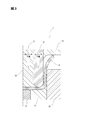
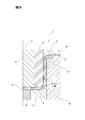
図1は、プレス成形装置の概略構成図である。本実施形態では、カップ状の被加工材(以下、カップ状被加工材という)に対して、プレス成形装置1を用いてプレス加工を行うことにより、減肉及び増肉処理を実施する。ここで、カップ状被加工材とは、底壁部と、底壁部の外縁に形成された縦壁部とを有する有底筒状の加工材のことであり、後述するように底壁部にボス形状部が形成されたボス付きカップ状被加工材も含まれるものとする。 (First embodiment)
FIG. 1 is a schematic configuration diagram of a press molding apparatus. In the present embodiment, the thickness reduction and the thickness increase processing are performed by performing press processing on the cup-shaped workpiece (hereinafter referred to as cup-shaped workpiece) using the
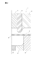
上述の実施形態では、カップ状被加工材Bの底壁部が径方向にフラットである場合について説明したが、本発明はこれに限るものではない。図6は、図4に対応しており、変形例1のカップ状被加工材B’を示している。図6に示すように、本発明のカップ状被加工材には、底壁部の径方向中心側に形成されるとともに、カップ内側に向かって突出し、かつ、第2の挟圧部B2よりも高さが低いボス形状部B1’を備えたボス付きカップ状被加工材B’も含まれる。この場合、ボス形状部B1’が、上述の実施形態における第1の挟圧部B1に相当する。 (Modification 1)
In the above-described embodiment, the case where the bottom wall portion of the cup-shaped workpiece B is flat in the radial direction has been described, but the present invention is not limited thereto. FIG. 6 corresponds to FIG. 4 and shows a cup-shaped workpiece B ′ of
上述の実施形態では、内パンチ11、中パンチ12及び外パンチ13を上側に配置し、内ダイ14、中ダイ15及び外ダイ16を下側に配置したが、本発明はこれに限るものではなく、上下の配置を反対にしてもよい。この場合、第1の挟圧部B1を挟圧する内パンチ11及び内ダイ14を下動させながら、内ダイ14を内パンチ11に向かって押し込む。また、第2の挟圧部B2を挟圧する外パンチ13及び外ダイ16を上動させて、第2の挟圧部B2における材料流動を抑制する。これにより、上述の実施形態と同様の減肉増肉処理を実施することができる。 (Modification 2)
In the above-described embodiment, the
第1実施形態では、カップ状被加工材の減肉増肉処理の際に、内パンチ11及び内ダイ14を中ダイ15から離隔する方向に動かしながら、第1の挟圧部B1の減肉処理を実施したが、本実施形態では、第1の挟圧部B1の減肉処理を第1実施形態とは異なるタイミングで実施する。本実施形態において用いられるプレス成形装置1の装置構成は、第1実施形態と同様であるため、説明を繰り返さない。 (Second Embodiment)
In the first embodiment, the thickness reduction of the first clamping portion B1 is performed while moving the
本実施形態では、図8に図示する増肉工程を実施する前に、第1の挟圧部B1を減肉する減肉処理を実施したが、本発明はこれに限られるものではなく、第1実施形態と同様、増肉工程を実施しながら第1の挟圧部B1を減肉する減肉工程を含んでいてもよい。この場合、減肉処理は、増肉工程前と、増肉工程中との二段階で実施される。 (Modification 3)
In the present embodiment, the thickness reducing process for reducing the thickness of the first clamping part B1 is performed before the thickness increasing process illustrated in FIG. 8 is performed. However, the present invention is not limited to this, Similarly to the first embodiment, a thickness reducing step for reducing the thickness of the first clamping part B1 may be included while performing the thickness increasing step. In this case, the thinning process is performed in two stages, before the thickening process and during the thickening process.
上述の実施形態では、円板状被加工材Aをカップ状被加工材Bに成形する際にプレス成形装置1を用いたが、本発明はこれに限るものではなく、他のプレス成形装置を用いることもできる。つまり、円板状被加工材Aをカップ状被加工材Bに成形する工程と、減肉増肉工程とにおいて用いられるプレス成形装置は異なっていてもよい。 (Modification 4)
In the above-described embodiment, the
上述の実施形態では、外パンチ13の先端部には、中心軸10に接近するほど下側に湾曲するパンチ肩部が形成されている。これに対し、外パンチ13の先端部が、径方向に延びるフラットな形状に形成されていてもよい。この場合でも同様に、減肉増肉処理が可能である。更に、外パンチ13の先端部を、湾曲形状ではなくフラット形状にすることにより、材料の流動抵抗が増し、第2の挟圧部B2が中心軸10から離隔する方向に材料流動するのをより抑制することができる。 (Modification 5)
In the above-described embodiment, a punch shoulder portion that is curved downward as it approaches the
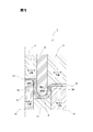
第1または第2実施形態において、第2の挟圧部B2が中心軸10から離隔する方向に材料流動するのをさらに抑制するには、摩擦抵抗を上げる必要がある。摩擦抵抗を上げるには、潤滑状態を変えて摩擦係数を上げるか、もしくは外パンチ13及び外ダイ16のカップ状被加工材Bを狭圧する荷重を上げる方法がある。一方で、摩擦係数は荷重の関数であり、プレス成形装置1の最大荷重や、第2の挟圧部B2の成形板厚などの制約条件により取りうる値に制限がある。これに対し、図9に示した第3実施形態では、外ダイ26に設けた外ダイ凸部28により、図10のように第2の挟圧部B2を狭圧する際に、カップ状被加工材Bの外周部である第2の挟圧部B2を拘束し、中心軸10から離隔する方向に材料流動するのを拘束する。この結果、カップ状被加工材Bの縦壁部B3及びB4(図5、図8参照)への材料流動が増し、増肉率を高めることができる。 (Third embodiment)
In the first or second embodiment, it is necessary to increase the frictional resistance in order to further suppress the material flow of the second pinching part B2 in the direction away from the
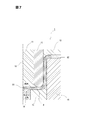
上述の実施形態では外ダイ26に外ダイ凸部28を設け、それに対向する外パンチ23に外ダイ凸部28が収まる外パンチ凹部27を設けている。これに対し、プレス成形装置1の荷重容量が十分高く、成形中に外パンチ23と外ダイ26が開いてしまうことがない場合は、外パンチ凹部27を設けず、図1に示した外パンチ13を用いてもよい。 (Modification 6)
In the above-described embodiment, the
上述の実施形態では、外パンチ23に凹部を、外ダイ26に凸部を配置したが、本発明はこれに限るものではなく、上下の配置を反対にしてもよい。この場合、外パンチ23に凸部を、外ダイ26に凹部を配置した金型構成で、上述の実施形態と同様の成形を行うことができる。 (Modification 7)
In the above-described embodiment, the concave portion is disposed on the
Claims (4)
- 各々の中心軸が同軸上に配置された内パンチ、前記内パンチの外周に沿って配置した中パンチ及び前記中パンチの外周に沿って配置した外パンチ、内ダイ、前記内ダイの外周に沿って配置した中ダイ、前記中ダイの外周に沿って配置した外ダイを有し、前記内パンチ、前記中パンチ及び前記外パンチが各々前記内ダイ、前記中ダイ及び前記外ダイに対向配置されたプレス金型を用いたプレス成形方法であって、
カップ状に形成された被加工材の底壁部における第1の挟圧部を、前記内パンチ及び前記内ダイで挟圧して前記中ダイから離隔する方向に移動させながら、前記内ダイを前記内パンチに向かって押し込むとともに、
前記被加工材の径方向外側端部である第2の挟圧部を、挟圧する前記外パンチ及び前記外ダイで挟圧して前記中ダイに接近する方向に移動させて、前記第2の挟圧部における前記被加工材が前記中心軸から離隔する方向に材料流動するのを抑制することにより、
前記第1の挟圧部の減肉処理と、前記中パンチと前記内ダイとで挟まれた前記被加工材の縦壁部と、前記中パンチと前記外ダイとで挟まれた前記被加工材の縦壁部との増肉処理を実施することを特徴とするプレス成形方法。 An inner punch in which each central axis is coaxially arranged, an intermediate punch arranged along the outer periphery of the inner punch, an outer punch arranged along the outer periphery of the intermediate punch, an inner die, and an outer periphery of the inner die The inner die, the outer die arranged along the outer periphery of the middle die, and the inner punch, the middle punch, and the outer punch are respectively disposed facing the inner die, the middle die, and the outer die. A press molding method using a press die,
The first die pressing portion in the bottom wall portion of the workpiece formed in a cup shape is clamped by the inner punch and the inner die and moved in a direction away from the middle die, while moving the inner die While pushing toward the inner punch,
A second pinching portion, which is a radially outer end portion of the workpiece, is pinched by the outer punch to be pinched and the outer die and moved in a direction approaching the middle die, so that the second pinching portion is moved. By suppressing the material flow in the direction away from the central axis of the workpiece in the pressure part,
The thinning process of the first clamping part, the vertical wall part of the workpiece sandwiched between the middle punch and the inner die, and the workpiece sandwiched between the middle punch and the outer die. A press molding method characterized by performing a thickening process with a vertical wall portion of a material. - カップ状に形成された被加工材の外周部を拘束する凸部を外パンチ、もしくは外ダイに設け、前記被加工材の径方向外側端部である第2の挟圧部において、前記被加工材が前記中心軸から離隔する方向に材料流動するのを拘束することを特徴とする請求項1に記載のプレス成形方法。 A convex portion that constrains the outer peripheral portion of the workpiece formed in a cup shape is provided on the outer punch or the outer die, and the workpiece is processed in the second clamping portion that is the radially outer end portion of the workpiece. The press molding method according to claim 1, wherein the material is restrained from flowing in a direction away from the central axis.
- 各々の中心軸が同軸上に配置された内パンチ、前記内パンチの外周に沿って配置した中パンチ及び前記中パンチの外周に沿って配置した外パンチ、内ダイ、前記内ダイの外周に沿って配置した中ダイ、前記中ダイの外周に沿って配置した外ダイを有し、前記内パンチ、前記中パンチ及び前記外パンチが各々前記内ダイ、前記中ダイ及び前記外ダイに対向配置されたプレス金型を用いたプレス成形方法であって、
カップ状に形成された被加工材の底壁部における第1の挟圧部を前記内パンチ及び前記内ダイで挟圧することにより減肉処理を実施し、
減肉された前記第1の挟圧部を、前記内パンチ及び前記内ダイで挟んで前記中ダイから離隔する方向に移動させながら、
前記被加工材の径方向外側端部である第2の挟圧部を、前記外パンチ及び前記外ダイで挟圧して前記中ダイに接近する方向に移動させて、前記第2の挟圧部が前記中心軸から離隔する方向に材料流動するのを抑制することにより、
前記中パンチと前記内ダイとで挟まれた前記被加工材の縦壁部と、前記中パンチと前記外ダイとで挟まれた前記被加工材の縦壁部との増肉処理を実施することを特徴とするプレス成形方法。 An inner punch in which each central axis is coaxially arranged, a middle punch arranged along the outer circumference of the inner punch, an outer punch arranged along the outer circumference of the middle punch, an inner die, and an outer circumference of the inner die The inner die, the outer die arranged along the outer periphery of the middle die, and the inner punch, the middle punch, and the outer punch are respectively disposed facing the inner die, the middle die, and the outer die. A press molding method using a press die,
A thickness reduction process is performed by clamping the first clamping part in the bottom wall part of the workpiece formed in a cup shape with the inner punch and the inner die,
While moving the reduced thickness of the first clamping portion between the inner punch and the inner die in a direction away from the middle die,
A second pinching portion, which is a radially outer end portion of the workpiece, is clamped by the outer punch and the outer die and moved in a direction approaching the middle die, and the second pressing portion By suppressing the material flow in the direction away from the central axis,
A thickness increasing process is performed between the vertical wall portion of the workpiece sandwiched between the intermediate punch and the inner die and the vertical wall portion of the workpiece sandwiched between the intermediate punch and the outer die. The press molding method characterized by the above-mentioned. - カップ状に形成された被加工材の外周部を拘束する凸部を外パンチ、もしくは外ダイに設け、前記被加工材の径方向外側端部である第2の挟圧部において、前記被加工材が前記中心軸から離隔する方向に材料流動するのを拘束することを特徴とする請求項3に記載のプレス成形方法。 A convex portion that constrains the outer peripheral portion of the workpiece formed in a cup shape is provided on the outer punch or the outer die, and the workpiece is processed in the second clamping portion that is the radially outer end portion of the workpiece. The press molding method according to claim 3, wherein the material is restrained from flowing in a direction away from the central axis.
Priority Applications (6)
| Application Number | Priority Date | Filing Date | Title |
|---|---|---|---|
| JP2014515743A JP5618030B1 (en) | 2012-11-09 | 2013-11-07 | Press forming method |
| US14/425,552 US9707617B2 (en) | 2012-11-09 | 2013-11-07 | Press-forming method |
| IN1924DEN2015 IN2015DN01924A (en) | 2012-11-09 | 2013-11-07 | |
| MX2015003951A MX354007B (en) | 2012-11-09 | 2013-11-07 | Press molding method. |
| KR1020157007100A KR101637139B1 (en) | 2012-11-09 | 2013-11-07 | Press molding method |
| CN201380056426.2A CN104768671B (en) | 2012-11-09 | 2013-11-07 | Impact forming method |
Applications Claiming Priority (2)
| Application Number | Priority Date | Filing Date | Title |
|---|---|---|---|
| JP2012247286 | 2012-11-09 | ||
| JP2012-247286 | 2012-11-09 |
Publications (1)
| Publication Number | Publication Date |
|---|---|
| WO2014073602A1 true WO2014073602A1 (en) | 2014-05-15 |
Family
ID=50684702
Family Applications (1)
| Application Number | Title | Priority Date | Filing Date |
|---|---|---|---|
| PCT/JP2013/080101 WO2014073602A1 (en) | 2012-11-09 | 2013-11-07 | Press molding method |
Country Status (7)
| Country | Link |
|---|---|
| US (1) | US9707617B2 (en) |
| JP (1) | JP5618030B1 (en) |
| KR (1) | KR101637139B1 (en) |
| CN (1) | CN104768671B (en) |
| IN (1) | IN2015DN01924A (en) |
| MX (1) | MX354007B (en) |
| WO (1) | WO2014073602A1 (en) |
Families Citing this family (9)
| Publication number | Priority date | Publication date | Assignee | Title |
|---|---|---|---|---|
| CN106102948B (en) * | 2014-03-28 | 2018-01-26 | 新日铁住金株式会社 | The manufacture method of tabular formed body with multiple thickenings and the tabular formed body with multiple thickened sections |
| EP3238845B1 (en) * | 2014-12-25 | 2021-12-22 | Nippon Steel Corporation | Panel-shaped molded article and production method for panel-shaped molded article |
| CN108025344B (en) * | 2015-09-18 | 2020-08-25 | 日本制铁株式会社 | Plate-shaped molded article and method for producing same |
| DE102016205492A1 (en) * | 2016-04-04 | 2017-10-05 | Thyssenkrupp Ag | Method and device for forming a semifinished product |
| CN106944545A (en) * | 2017-03-25 | 2017-07-14 | 亿森(上海)模具有限公司 | Moulding face different coefficients of friction and controllable forming method |
| EP3678795A1 (en) * | 2017-09-05 | 2020-07-15 | ThyssenKrupp Steel Europe AG | Method for producing a component and tool therefor |
| US11684963B2 (en) * | 2017-10-12 | 2023-06-27 | Nippon Steel Corporation | Method and apparatus for producing outer panel having character line |
| JP7403794B2 (en) | 2019-11-07 | 2023-12-25 | 太陽工業株式会社 | Double acting press mold |
| CN111496067B (en) * | 2020-06-01 | 2022-03-18 | 昆山信创电子有限公司 | Continuous die stretching process for router accessories and die thereof |
Citations (6)
| Publication number | Priority date | Publication date | Assignee | Title |
|---|---|---|---|---|
| JPS6449326U (en) * | 1987-09-16 | 1989-03-27 | ||
| JPH07185726A (en) * | 1993-12-27 | 1995-07-25 | Honda Motor Co Ltd | Method for press thickening work |
| JPH10296377A (en) * | 1997-04-25 | 1998-11-10 | Press Kogyo Co Ltd | Cup like parts and production therefor |
| JP2000301284A (en) * | 1999-04-23 | 2000-10-31 | Toyota Motor Corp | Method for upsetting and thickness increasing ring- shaped pressed article |
| JP2000317565A (en) * | 1999-05-11 | 2000-11-21 | Toyota Motor Corp | Upsetting-press thickening method of press fromed part |
| JP2004322104A (en) * | 2003-04-21 | 2004-11-18 | Aisin Seiki Co Ltd | Drawing die and drawing method |
Family Cites Families (10)
| Publication number | Priority date | Publication date | Assignee | Title |
|---|---|---|---|---|
| US5329799A (en) * | 1992-05-29 | 1994-07-19 | Toyota Jidosha Kabushiki Kaisha | Process and apparatus for press-forming tubular container-like article from strip, including forward and backward ironing steps |
| US6290447B1 (en) * | 1995-05-31 | 2001-09-18 | M.S. Willett, Inc. | Single station blanked, formed and curled can end with outward formed curl |
| JPH09295088A (en) * | 1996-03-04 | 1997-11-18 | Matsushita Electric Ind Co Ltd | Bottomed cylindrical body and its manufacture |
| JP3425068B2 (en) * | 1997-09-24 | 2003-07-07 | アイダエンジニアリング株式会社 | Method and apparatus for forming stepped cup-shaped member with flange |
| US6701603B2 (en) * | 2000-12-13 | 2004-03-09 | Asmo Co., Ltd. | Method of manufacturing yoke of electric rotating machine |
| US7264611B2 (en) * | 2002-05-31 | 2007-09-04 | Medtronic, Inc. | Implantable infusion device with motor connection and seal system |
| RU2354485C2 (en) * | 2004-07-29 | 2009-05-10 | Бол Корпорейшн | Method and device for end cover shaping in metal containers |
| JP4522378B2 (en) * | 2005-04-20 | 2010-08-11 | ジヤトコ株式会社 | Press molding method and apparatus |
| JP5244529B2 (en) * | 2008-10-09 | 2013-07-24 | しのはらプレスサービス株式会社 | Thickening press processing method with vertical press |
| JP5262872B2 (en) * | 2009-03-13 | 2013-08-14 | アイシン・エィ・ダブリュ株式会社 | Stepping cup-shaped part forming apparatus and forming method |
-
2013
- 2013-11-07 CN CN201380056426.2A patent/CN104768671B/en active Active
- 2013-11-07 KR KR1020157007100A patent/KR101637139B1/en active IP Right Grant
- 2013-11-07 IN IN1924DEN2015 patent/IN2015DN01924A/en unknown
- 2013-11-07 MX MX2015003951A patent/MX354007B/en active IP Right Grant
- 2013-11-07 US US14/425,552 patent/US9707617B2/en active Active
- 2013-11-07 JP JP2014515743A patent/JP5618030B1/en active Active
- 2013-11-07 WO PCT/JP2013/080101 patent/WO2014073602A1/en active Application Filing
Patent Citations (6)
| Publication number | Priority date | Publication date | Assignee | Title |
|---|---|---|---|---|
| JPS6449326U (en) * | 1987-09-16 | 1989-03-27 | ||
| JPH07185726A (en) * | 1993-12-27 | 1995-07-25 | Honda Motor Co Ltd | Method for press thickening work |
| JPH10296377A (en) * | 1997-04-25 | 1998-11-10 | Press Kogyo Co Ltd | Cup like parts and production therefor |
| JP2000301284A (en) * | 1999-04-23 | 2000-10-31 | Toyota Motor Corp | Method for upsetting and thickness increasing ring- shaped pressed article |
| JP2000317565A (en) * | 1999-05-11 | 2000-11-21 | Toyota Motor Corp | Upsetting-press thickening method of press fromed part |
| JP2004322104A (en) * | 2003-04-21 | 2004-11-18 | Aisin Seiki Co Ltd | Drawing die and drawing method |
Also Published As
| Publication number | Publication date |
|---|---|
| US9707617B2 (en) | 2017-07-18 |
| KR101637139B1 (en) | 2016-07-06 |
| MX2015003951A (en) | 2015-07-06 |
| MX354007B (en) | 2018-02-08 |
| CN104768671B (en) | 2016-08-31 |
| JPWO2014073602A1 (en) | 2016-09-08 |
| KR20150046223A (en) | 2015-04-29 |
| JP5618030B1 (en) | 2014-11-05 |
| US20150231688A1 (en) | 2015-08-20 |
| IN2015DN01924A (en) | 2015-08-07 |
| CN104768671A (en) | 2015-07-08 |
Similar Documents
| Publication | Publication Date | Title |
|---|---|---|
| JP5618030B1 (en) | Press forming method | |
| JP5610104B1 (en) | Press working method and bottomed container | |
| JP5626500B1 (en) | Press forming method | |
| JP5741771B2 (en) | Press forming method | |
| JP2014521518A (en) | Can manufacturing method and can manufacturing apparatus | |
| JP2014133260A (en) | Press component molding method, press component manufacturing method, and press component molding die | |
| JPWO2012127726A1 (en) | Tooth profile part manufacturing method, tooth profile part manufacturing apparatus, and tooth profile part | |
| JP2003117619A (en) | Press forming method and device used therefor | |
| JPS6358651B2 (en) | ||
| JP6242363B2 (en) | Molding material manufacturing method | |
| JP4433649B2 (en) | Method for forming a product with a flange | |
| JP5941369B2 (en) | Hydraulic molding method and hydraulic molding apparatus | |
| JP5268715B2 (en) | Manufacturing method of connecting rod and coining type apparatus used therefor | |
| JP2001259750A (en) | Forming method of metal product and forming die used therefor | |
| JP2007181878A (en) | Flanged housing member, and method and apparatus for forming same | |
| JP2002346682A (en) | Method for upset burring of thick plate and its mold | |
| CN106964733B (en) | Annular special process for manufacturing forging | |
| JP5554424B2 (en) | Molding method of tooth profile parts | |
| JP7417069B2 (en) | Molded material manufacturing method | |
| TW201813736A (en) | Formed material manufacturing method and formed material | |
| JP6537151B1 (en) | Projection forming method, projection forming system, and method of manufacturing metal part having projection | |
| JP2023080754A (en) | Sizing device | |
| JP2014091148A (en) | Press forming method of cup-shaped member | |
| JP2005103618A (en) | Method for manufacturing pulley | |
| JP2020127957A (en) | Molding method and molding apparatus for annular members |
Legal Events
| Date | Code | Title | Description |
|---|---|---|---|
| ENP | Entry into the national phase |
Ref document number: 2014515743 Country of ref document: JP Kind code of ref document: A |
|
| 121 | Ep: the epo has been informed by wipo that ep was designated in this application |
Ref document number: 13853908 Country of ref document: EP Kind code of ref document: A1 |
|
| WWE | Wipo information: entry into national phase |
Ref document number: 14425552 Country of ref document: US |
|
| ENP | Entry into the national phase |
Ref document number: 20157007100 Country of ref document: KR Kind code of ref document: A |
|
| WWE | Wipo information: entry into national phase |
Ref document number: MX/A/2015/003951 Country of ref document: MX |
|
| WWE | Wipo information: entry into national phase |
Ref document number: IDP00201502778 Country of ref document: ID |
|
| NENP | Non-entry into the national phase |
Ref country code: DE |
|
| 122 | Ep: pct application non-entry in european phase |
Ref document number: 13853908 Country of ref document: EP Kind code of ref document: A1 |