RU2354485C2 - Method and device for end cover shaping in metal containers - Google Patents
Method and device for end cover shaping in metal containers Download PDFInfo
- Publication number
- RU2354485C2 RU2354485C2 RU2007107367/02A RU2007107367A RU2354485C2 RU 2354485 C2 RU2354485 C2 RU 2354485C2 RU 2007107367/02 A RU2007107367/02 A RU 2007107367/02A RU 2007107367 A RU2007107367 A RU 2007107367A RU 2354485 C2 RU2354485 C2 RU 2354485C2
- Authority
- RU
- Russia
- Prior art keywords
- tool
- specified
- undercut
- clamping
- panel
- Prior art date
Links
Images
Classifications
-
- B—PERFORMING OPERATIONS; TRANSPORTING
- B21—MECHANICAL METAL-WORKING WITHOUT ESSENTIALLY REMOVING MATERIAL; PUNCHING METAL
- B21D—WORKING OR PROCESSING OF SHEET METAL OR METAL TUBES, RODS OR PROFILES WITHOUT ESSENTIALLY REMOVING MATERIAL; PUNCHING METAL
- B21D22/00—Shaping without cutting, by stamping, spinning, or deep-drawing
- B21D22/20—Deep-drawing
- B21D22/24—Deep-drawing involving two drawing operations having effects in opposite directions with respect to the blank
-
- B—PERFORMING OPERATIONS; TRANSPORTING
- B21—MECHANICAL METAL-WORKING WITHOUT ESSENTIALLY REMOVING MATERIAL; PUNCHING METAL
- B21D—WORKING OR PROCESSING OF SHEET METAL OR METAL TUBES, RODS OR PROFILES WITHOUT ESSENTIALLY REMOVING MATERIAL; PUNCHING METAL
- B21D51/00—Making hollow objects
- B21D51/16—Making hollow objects characterised by the use of the objects
- B21D51/38—Making inlet or outlet arrangements of cans, tins, baths, bottles, or other vessels; Making can ends; Making closures
Landscapes
- Engineering & Computer Science (AREA)
- Mechanical Engineering (AREA)
- Rigid Containers With Two Or More Constituent Elements (AREA)
- Closing Of Containers (AREA)
- Forging (AREA)
- Containers Having Bodies Formed In One Piece (AREA)
- Cable Accessories (AREA)
Abstract
Description
Область техники, к которой относится изобретениеFIELD OF THE INVENTION
Настоящее изобретение относится к производственному процессу формирования металлической тары и торцевых крышек для тары и, в частности, к способу и устройству для получения высокопрочной геометрической формы при одновременном сохранении необходимых характеристик зажимной стенки и закатываемой панели.The present invention relates to the manufacturing process of forming metal containers and end caps for containers and, in particular, to a method and apparatus for obtaining a high-strength geometric shape while maintaining the necessary characteristics of the clamping wall and the roll-up panel.
Предпосылки создания изобретенияBACKGROUND OF THE INVENTION
Торцевые крышки металлических банок для напитков исторически проектировались и производились так, чтобы обеспечить наличие буртика жесткости, известного как поднутрение. Эта отличительная особенность может предусматривать наличие вертикальных стенок со дна по всему радиусу с образованием канала, а в некоторых вариантах осуществления изобретения могут иметься дугообразные формы или другие геометрические профили. Строго вертикальные стенки могут и отсутствовать, но, как правило, чем отвеснее стенки, тем выше сопротивление деформациям, возникающим под воздействием внутреннего давления.The end caps of metal beverage cans have historically been designed and manufactured to provide a stiffening collar known as undercut. This feature may include vertical walls from the bottom along the entire radius to form a channel, and in some embodiments of the invention there may be arched shapes or other geometric profiles. Strictly vertical walls may be absent, but, as a rule, the steeper the walls, the higher the resistance to deformations arising under the influence of internal pressure.
Корпуса и торцевые крышки банок для налитков должны быть достаточно прочными, чтобы выдерживать высокое внутреннее давление и в то же время изготавливаться из очень тонких и прочных материалов, таких как алюминий, чтобы уменьшить общие производственные затраты и снизить вес готового продукта. Таким образом, существует большая потребность в прочных торцевых крышках банок для напитков, способных противостоять воздействию высокого внутреннего давления, создаваемого газированными напитками, и внешних нагрузок, возникающих при перевозке, и сделанных из прочных, легких и очень тонких металлических материалов с использованием геометрических форм, уменьшающих потребность в материалах. Чтобы обеспечить получение этих характеристик, для торцевых крышек банок требуется проводить интенсивную обработку материалов, придавая им различную геометрическую форму, а это обычно осуществляется с использованием соответствующих наборов выпуклых и вогнутых инструментов. К сожалению, этот процесс может приводить к отклонениям от установленного контура или геометрии. Отклонения от требуемой формы сказываются также и на прочностных показателях. Интенсивное формообразование в области поднутрения может повлиять и на другие характеристики в сей конструкции в целом. Таким образом, существует насущная потребность в разработке оборудования и технологии для придания формы материалам, которые обеспечат получение торцевых крышек лучшего качества с оптимальной геометрией тары, обладающей повышенной прочностью и сопротивлением продольному изгибу. Эти отличительные особенности достигаются в одном из вариантов осуществления изобретения благодаря тому, что материал торцевых крышек подвергается сжатию в процессе придания ему формы, чтобы избежать утончения и нежелательных деформаций материала, и в то же время для определения участков и закатываемого гребня торцевой крышки в процессе их формирования обеспечивается опора, а другие участки такой опоры не имеют, чтобы получить заранее определенную форму.The casings and end caps of the cans must be strong enough to withstand high internal pressure and at the same time be made of very thin and durable materials such as aluminum to reduce overall manufacturing costs and reduce the weight of the finished product. Thus, there is a great need for durable end caps for beverage cans that can withstand the high internal pressure created by carbonated drinks and the external loads that occur during transportation and are made of strong, light and very thin metal materials using geometric shapes that reduce need for materials. To ensure obtaining these characteristics, for the end caps of cans, intensive processing of materials is required, giving them a different geometric shape, and this is usually done using appropriate sets of convex and concave tools. Unfortunately, this process can lead to deviations from the established contour or geometry. Deviations from the required shape also affect strength indicators. Intensive shaping in the undercut area can affect other characteristics in this design as a whole. Thus, there is an urgent need to develop equipment and technology for shaping materials that will provide better end caps with optimal packaging geometry, which has increased strength and resistance to longitudinal bending. These distinctive features are achieved in one embodiment of the invention due to the fact that the material of the end caps is compressed in the process of shaping to avoid thinning and undesirable deformation of the material, and at the same time to determine the sections and rolled crest of the end cap in the process of their formation a support is provided, and other sections of such a support do not have to get a predetermined shape.
Одно из технических решений, относящихся к способу и устройству для получения поднутрения в торцевых крышек для металлической тары, описывается в патенте США №5685189 («патент '189»), который посредством ссылки на него полностью включается в данное описание. В патенте '189 участок поднутрения формируется без обеспечения для него опоры со стороны технологической оснастки, в то время как сам этот участок подвергается сжатию. К сожалению, оказалось, что при меньшей толщине применяемых исходных материалов этот процесс приводит к нежелательной деформации зажимной стенки и закатываемого гребня, а следовательно, и к отклонениям от требуемой геометрии торцевой крышки.One of the technical solutions related to the method and device for obtaining undercut in the end caps for metal containers is described in US patent No. 5685189 ("patent '189"), which by reference to it is fully included in this description. In the '189 patent, an undercut section is formed without providing support for it from the tooling side, while this section itself is subjected to compression. Unfortunately, it turned out that with a smaller thickness of the starting materials used, this process leads to undesirable deformation of the clamping wall and the rolled crest, and therefore to deviations from the required geometry of the end cap.
Раскрытие изобретенияDisclosure of invention
Настоящее изобретение относится к устройству и способу для формирования тары и торцевых крышек предпочтительной геометрической формы с использованием тонкостенных материалов (толщиной 0,0084 дюйма или меньше) и обеспечением улучшенных прочностных показателей и свойств материала. Таким образом, одной из особенностей настоящего изобретения является использование процесса «свободного формирования» в при производстве торцевых крышек для металлической тары, при этом, по меньшей мере, некоторая часть материала подвергается во время формирования сжатию, и таким образом уменьшается вероятность «калибровки» или утончения и в конечном итоге ослабления получаемой продукции. Другой особенностью настоящего изобретения является создание способа и устройства для придания заранее определенной формы металлическому материалу, при этом некоторая часть материала остается при формообразовании без опоры. Таким образом часть металлического материала «свободно приобретает» желаемую форму без существенной опоры как для всей верхней или нижней поверхности материала.The present invention relates to a device and method for forming containers and end caps of a preferred geometric shape using thin-walled materials (0.0084 inches thick or less) and providing improved strength and material properties. Thus, one of the features of the present invention is the use of the “free formation” process in the manufacture of end caps for metal containers, with at least some of the material being compressed during formation, and thereby reducing the likelihood of “calibration” or thinning and ultimately weakening the resulting product. Another feature of the present invention is the creation of a method and device for giving a predetermined shape to a metal material, while some of the material remains unformed during shaping. Thus, a part of the metal material “freely acquires” the desired shape without substantial support as for the entire upper or lower surface of the material.
Еще одной особенностью настоящего изобретения является создание формовочного процесса, обеспечивающего получение предпочтительной геометрической формы металлических торцевых крышек с высокой скоростью, присущей известным технологиям, и с повышенной надежностью. Так, в соответствии с одной из особенностей изобретения предусматривается применение внутренней нажимной втулки наряду с обеспечением критических параметров формообразования, чтобы добиться получения заданной геометрии крышки при скорости процесса 1800-11000 крышек в минуту.Another feature of the present invention is the creation of a molding process that provides the preferred geometric shape of the metal end caps with high speed inherent in known technologies, and with increased reliability. So, in accordance with one of the features of the invention provides for the use of an internal pressure sleeve along with providing critical forming parameters in order to achieve a given geometry of the lid at a process speed of 1800-11000 lids per minute.
Еще одна отличительная особенность настоящего изобретения заключается в использовании внутренней нажимной втулки, которая приводится в действие штырями либо пневматическим поршнем, пружинной пластиной или отдельными пружинами, создающими достаточное усилие, чтобы обеспечить опору для части зажимной стенки торцевой крышки при формировании предпочтительной геометрической ее формы в процессе изготовления.Another distinctive feature of the present invention is the use of an internal pressure sleeve, which is driven by pins or a pneumatic piston, a spring plate or individual springs that create sufficient force to provide support for part of the clamping wall of the end cover when forming its preferred geometric shape during manufacturing .
Следующая особенность настоящего изобретения заключается в создании устройства и способа для формирования торцевой крышки тары предпочтительной геометрической формы, причем некоторые части торцевой крышки получают опору как для внутренней, так и для внешней поверхности, чтобы предотвратить смещение и нежелательную деформацию, в то время как другая ее часть «свободно приобретает нужную форму». Так, в соответствии с одной из особенностей осуществления настоящего изобретения, предусматривается применение «нажимной втулки», расположенной напротив кольцевого сердечника штампа и использующейся для того, чтобы обеспечить опору для зажимной стенки торцевой крышки и/или среднего участка закатываемой панели в процессе формирования, в то время как, по меньшей мере, часть поднутрения подвержена сжатию для получения предпочтительной геометрической формы. A further feature of the present invention is to provide a device and method for forming an end cap of a container of a preferred geometric shape, wherein some parts of the end cap receive support for both the inner and outer surfaces to prevent displacement and undesired deformation, while the other part thereof "Freely acquires the desired form." So, in accordance with one of the features of the implementation of the present invention, the use of a “push sleeve”, located opposite the annular core of the stamp and used to provide support for the clamping wall of the end cover and / or the middle portion of the roll-up panel during the formation, while at least part of the undercut is subject to compression to obtain a preferred geometric shape.
Таким образом, одной из отличительных особенностей настоящего изобретения является создание устройства для получения предпочтительной геометрической формы металлической заготовки при изготовлении торцевой крышки с нужной геометрической формой для тары под напитки. Еще одной отличительной особенностью настоящего изобретения также является создание способа и устройства для получения улучшенной геометрической формы торцевой крышки, в основном, с использованием оборудования, хорошо известного в области изготовления торцевых крышек для тары и требующего лишь незначительных изменений. В одном из вариантов осуществления настоящего изобретения создано устройство для формирования металлических торцевых крышек, которое в общем содержитThus, one of the distinguishing features of the present invention is the creation of a device for obtaining the preferred geometric shape of the metal workpiece in the manufacture of the end cap with the desired geometric shape for containers for drinks. Another distinctive feature of the present invention is also the creation of a method and apparatus for obtaining an improved geometric shape of the end cap, mainly using equipment well known in the field of manufacturing end caps for containers and requiring only minor changes. In one of the embodiments of the present invention, a device for forming a metal end caps, which generally contains
первый инструмент, расположенный напротив второго инструмента, который предназначен для обеспечения зажимного усилия на участке закатываемой панели металлического материала;a first tool located opposite the second tool, which is designed to provide clamping forces in the area of the rolled-up panel of metal material;
третий инструмент, расположенный напротив четвертого инструмента, который предназначен для обеспечения зажимного усилия на участке центральной панели металлического материала;a third tool, located opposite the fourth tool, which is designed to provide clamping forces on the plot of the Central panel of the metal material;
пятый инструмент, расположенный между указанным первым инструментом и указанным третьим инструментом, который предназначен для того, чтобы обеспечить опору, по меньшей мере, для части зажимной стенки указанного металлического материала,a fifth tool located between said first tool and said third tool, which is designed to provide support for at least a portion of the clamping wall of said metal material,
и средства обеспечения возвратно-поступательного движения, по меньшей мере, между указанным пятым инструментом и указанными первым и вторым инструментами, в то время как часть поднутрения в торцевой крышке тары остается без опоры, при этом обеспечивается в зоне поднутрения утолщение материала при придании ему предпочтительной геометрической формы, что позволяет избежать уменьшения толщины материала в зоне поднутрения.and means for providing reciprocating movement between at least the fifth tool and the first and second tools, while part of the undercut in the end cap of the container is left unsupported, while thickening of the material is ensured in the undercut zone while giving it a preferred geometric shape, which avoids reducing the thickness of the material in the undercut zone.
Другой отличительной особенностью настоящего изобретения является создание способа для получения заранее определенной формы торцевой крышки для металлической тары, содержащей закатываемую панель, соединенную с нисходящей зажимной стенкой, центральную панель, имеющую вертикальную центральную ось, и поднутрение, соединенное с нижней частью зажимной стенки и центральной панели, при осуществлении которого предусматриваетсяAnother distinctive feature of the present invention is the creation of a method for obtaining a predetermined shape of the end cap for a metal container containing a roll-up panel connected to a downward clamping wall, a central panel having a vertical central axis, and an undercut connected to the lower part of the clamping wall and the central panel, the implementation of which provides
установка заготовки для торцевой крышки в заданном положении в формовочном прессе;setting the blank for the end cap in a predetermined position in the molding press;
обеспечение зажимного усилия, по меньшей мере, на части закатываемой панели между первым инструментом и вторым инструментом;providing a clamping force on at least a portion of the roll-up panel between the first tool and the second tool;
обеспечение зажимного усилия, по меньшей мере, на части центральной панели между третьим инструментом и четвертым инструментом с целью, по существу, предотвратить перемещение центральной панели;providing a clamping force on at least a portion of the center panel between the third tool and the fourth tool in order to substantially prevent the movement of the center panel;
обеспечение опоры, по меньшей мере, для части зажимной стенки как на внутренней, так и на внешней поверхности, чтобы по существу предотвратить смещение, по меньшей мере, части зажимной стенки;providing support for at least a portion of the clamping wall on both the inner and outer surfaces to substantially prevent displacement of at least a portion of the clamping wall;
обеспечение опоры для первой части поднутрения, по меньшей мере, с помощью одного из указанных третьего и четвертого инструментов, тогда как другая часть поднутрения остается при этом без опорыproviding support for the first part of the undercut, at least with one of these third and fourth tools, while the other part of the undercut remains without support
и обеспечение усилия сжатия в зоне поднутрения при сохранении зажимной стенки в предпочтительном положении при образовании заранее определенной формы торцевой крышки.and providing a compressive force in the undercut zone while maintaining the clamping wall in a preferred position when a predetermined shape of the end cap is formed.
Краткое описание чертежейBrief Description of the Drawings
фиг.1 - вид спереди в вертикальном поперечном разрезе типичной торцевой крышки для тары для напитков;figure 1 is a front view in vertical cross section of a typical end cap for containers for drinks;
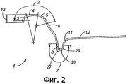
фиг.2 - вид спереди в вертикальном поперечном разрезе другого варианта исполнения торцевой крышки для тары для напитков;figure 2 is a front view in vertical cross section of another embodiment of the end cap for packaging for drinks;
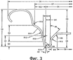
фиг.3 - вид спереди в вертикальном поперечном разрезе еще одного варианта исполнения торцевой крышки для тары для напитков;figure 3 is a front view in vertical cross section of another embodiment of the end cap for packaging for drinks;
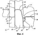
фиг.4 - вид спереди в вертикальном поперечном сечении торцевой крышки, формируемой в известном операционном формовочном прессе;4 is a front view in vertical cross section of an end cap formed in a known operational molding press;
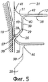
фиг.5 - вид спереди в вертикальном поперечном разрезе поднутрения торцевой крышки, показанной на фиг.4 в процессе формирования поднутрения;5 is a front view in vertical cross section of undercutting of the end cap shown in FIG. 4 in the process of forming the undercut;
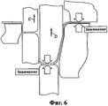
фиг.6 - вид спереди в вертикальном поперечном разрезе известного устройства, используемого для формирования торцевой крышки согласно патенту США №5685189;6 is a front view in vertical cross section of a known device used to form the end cap according to US patent No. 568189;
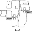
фиг.7 - вид спереди в вертикальном поперечном разрезе известного устройства, изображенного на фиг.6, где показано смещение зажимной стенки;Fig.7 is a front view in vertical cross section of a known device depicted in Fig.6, which shows the offset clamping wall;
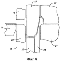
фиг.8 - вид спереди в вертикальном поперечном разрезе одного из вариантов осуществления настоящего изобретения, где показаны внутренняя нажимная втулка, прижатая к зажимной стенке, и силы, воздействующие на торцевую крышку во время формирования поднутрения;Fig is a front view in vertical cross section of one of the embodiments of the present invention, which shows the inner pressure sleeve pressed against the clamping wall, and the forces acting on the end cover during the formation of the undercut;
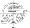
фиг.9 - схема, изображающая распределение во времени движения внутренней нажимной втулки в процессе цикла формирования: от верхней мертвой точки до нижней мертвой точки с возвратом в верхнюю мертвую точку;Fig.9 is a diagram depicting the time distribution of the movement of the inner pressure sleeve during the formation cycle: from top dead center to bottom dead center and returning to top dead center;
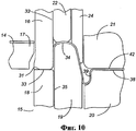
фиг.10 - вид спереди в вертикальном поперечном разрезе одного из вариантов осуществления настоящего изобретения, показанного в процессе формирования торцевой крышки, где внутренняя нажимная втулка обеспечивает опору для части зажимной стенки и среднего участка закатываемой панели;figure 10 is a front view in vertical cross section of one of the embodiments of the present invention, shown in the process of forming the end cap, where the inner pressure sleeve provides support for part of the clamping wall and the middle portion of the rolled panel;
фиг.11 - вид спереди в вертикальном поперечном разрезе, показывающий один из вариантов исполнения внутренней нажимной втулки;11 is a front view in vertical cross section showing one embodiment of an internal pressure sleeve;
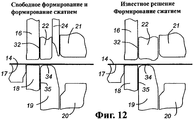
фиг.12 - сравнительный вид спереди в вертикальном поперечном разрезе известного формовочного устройства (на чертеже справа) и одного из новых вариантов осуществления настоящего изобретения (на чертеже слева) в процессе формирования;Fig is a comparative front view in vertical cross section of a known molding device (in the drawing on the right) and one of the new embodiments of the present invention (in the drawing on the left) in the formation process;
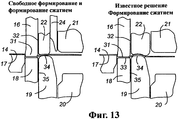
фиг.13 - сравнительный вид спереди в вертикальном поперечном разрезе известного формовочного устройства (на чертеже справа) и одного из новых вариантов осуществления настоящего изобретения (на чертеже слева) в процессе формирования;Fig - comparative front view in vertical cross section of a known molding device (in the drawing on the right) and one of the new embodiments of the present invention (in the drawing on the left) in the formation process;
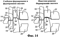
фиг.14 - сравнительный вид спереди в вертикальном поперечном разрезе известного формовочного устройства (на чертеже справа) и одного из новых вариантов осуществления настоящего изобретения (на чертеже слева) в процессе формирования;Fig - comparative front view in vertical cross section of a known molding device (in the drawing on the right) and one of the new embodiments of the present invention (in the drawing on the left) in the formation process;
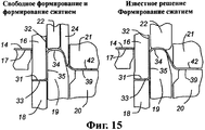
фиг.15 - сравнительный вид спереди в вертикальном поперечном разрезе известного формовочного устройства (на чертеже справа) и одного из новых вариантов осуществления настоящего изобретения (на чертеже слева) в процессе формирования;Fig - comparative front view in vertical cross section of a known molding device (in the drawing on the right) and one of the new embodiments of the present invention (in the drawing on the left) in the formation process;
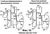
фиг.16 - сравнительный вид спереди в вертикальном поперечном разрезе известного формовочного устройства (на чертеже справа) и одного из новых вариантов осуществления настоящего изобретения (на чертеже слева) в процессе формирования;Fig is a comparative front view in vertical cross section of a known molding device (in the drawing on the right) and one of the new embodiments of the present invention (in the drawing on the left) in the formation process;
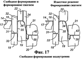
Фиг.17 - сравнительный вид спереди в вертикальном поперечном разрезе известного формовочного устройства (на чертеже справа) и одного из новых вариантов осуществления настоящего изобретения (на чертеже слева) в процессе формирования;Fig - comparative front view in vertical cross section of a known molding device (in the drawing on the right) and one of the new embodiments of the present invention (in the drawing on the left) in the formation process;
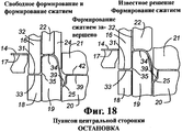
фиг.18 - сравнительный вид спереди в вертикальном поперечном разрезе известного формовочного устройства (на чертеже справа) и одного из новых вариантов осуществления настоящего изобретения (на чертеже слева) в процессе формирования;Fig is a comparative front view in vertical cross section of a known molding device (in the drawing on the right) and one of the new embodiments of the present invention (in the drawing on the left) in the formation process;
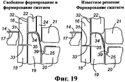
фиг.19 - сравнительный вид спереди в вертикальном поперечном разрезе известного формовочного устройства (на чертеже справа) и одного из новых вариантов осуществления настоящего изобретения (на чертеже слева) в процессе формирования;Fig is a comparative front view in vertical cross section of a known molding device (in the drawing on the right) and one of the new embodiments of the present invention (in the drawing on the left) in the formation process;
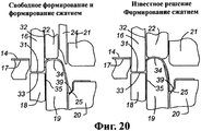
фиг.20 - сравнительный вид спереди в вертикальном поперечном разрезе известного формовочного устройства (на чертеже справа) и одного из новых вариантов осуществления настоящего изобретения (на чертеже слева) в процессе формирования;Fig. 20 is a comparative front view in vertical cross section of a known molding device (in the drawing on the right) and one of the new embodiments of the present invention (in the drawing on the left) during formation;
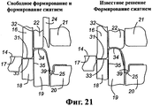
фиг.21 - сравнительный вид спереди в вертикальном поперечном разрезе известного формовочного устройства (на чертеже справа) и одного из новых вариантов осуществления настоящего изобретения (на чертеже слева) в процессе формирования;Fig is a comparative front view in vertical cross section of a known molding device (in the drawing on the right) and one of the new embodiments of the present invention (in the drawing on the left) in the formation process;
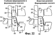
фиг.22 - сравнительный вид спереди в вертикальном поперечном разрезе известного формовочного устройства (на чертеже справа) и одного из новых вариантов осуществления настоящего изобретения (на чертеже слева) в процессе формирования;Fig is a comparative front view in vertical cross section of a known molding device (in the drawing on the right) and one of the new embodiments of the present invention (in the drawing on the left) in the formation process;
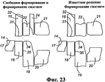
фиг.23 - сравнительный вид спереди в вертикальном поперечном разрезе известного формовочного устройства (на чертеже справа) и одного из новых вариантов осуществления настоящего изобретения (на чертеже слева) в процессе формирования;Fig is a comparative front view in vertical cross section of a known molding device (in the drawing on the right) and one of the new embodiments of the present invention (in the drawing on the left) in the formation process;
Хотя здесь и была предпринята попытка рассмотреть различные варианты исполнения предпочтительного варианта осуществления настоящего изобретения, специалисты легко могут предложить иные варианты осуществления изобретения. Поэтому следует понимать, что изобретение может быть реализовано в других конкретных формах с сохранением его сущности или основных отличительных признаков. Приводимые примеры и варианты осуществления должны, таким образом, рассматриваться во всех отношениях как пояснительные, но ни в коей мере не ограничительные, и настоящее изобретение не сводится исключительно только лишь к приведенным здесь его подробностям.Although an attempt has been made to consider various embodiments of a preferred embodiment of the present invention, those skilled in the art can readily offer other embodiments of the invention. Therefore, it should be understood that the invention can be implemented in other specific forms while preserving its essence or the main distinguishing features. The examples and embodiments provided should thus be construed in all respects as explanatory, but in no way restrictive, and the present invention is not limited solely to the details given here.
На чертежах показаны следующие составные элементы.The following components are shown in the drawings.
1 Незакатанная торцевая крышка банки для напитков1 Unopened end cover for beverage cans
2 Закатанная панель2 rolled up panel
3 Наружный радиус закатываемой панели3 Outer radius of the rolled-up panel
4 Радиус закатываемой панели4 Radius of the rolled up panel
5 Внутренний радиус закатываемой панели5 Inside radius of the rolled-up panel
6 Зажимная стенка6 Clamping wall
7 Поднутрение7 Undercut
8 Внешняя стенка панели поднутрения8 Outer wall of the undercut panel
9 Нижняя часть внутренней стенки панели поднутрения9 Bottom of the inner wall of the undercut panel
10 Внутренняя стенка панели поднутрения10 Inner wall of undercut panel
11 Радиус центральной панели11 Center panel radius
12 Центральная панель12 Center panel
13 Высота перед закатыванием13 Height before rolling
14 Металлический материал14 Metallic material
15 Конструкция штампа, показанная в положении остановки15 Stamp design shown in stop position
16 Пуансон заготовки16 Punch blank
17 Режущее ребро17 cutting rib
18 Прижимное кольцо18 pressure ring
19 Кольцевой сердечник штампа19 Ring die core
20 Пуансон панели20 punch panel
21 Пуансон поднутрения21 Undercut Punch
22 Внешняя нажимная втулка22 External pressure sleeve
23 Вытяжная доска23 Hood
24 Внутренняя нажимная втулка24 Internal pressure sleeve
25 Нижний конец внутренней стенки панели25 The lower end of the inner wall of the panel
26 Радиус чашки26 Cup radius
27 Первый радиус поднутрения27 First undercut radius
28 Второй радиус поднутрения28 Second undercut radius
29 Третий радиус поднутрения29 Third undercut radius
30 Дно чашки30 bottom of the cup
31 Поверхность пуансона заготовки31 The surface of the punch workpiece
32 Внутренний диаметр пуансона заготовки32 Inside diameter of the workpiece punch
33 Поверхность прижимного кольца33 The surface of the clamping ring
34 Верхняя поверхность кольцевого сердечника штампа34 The upper surface of the annular core of the stamp
35 Наружный диаметр кольцевого сердечника штампа35 Outer diameter of the annular core of the stamp
36 Внутренняя стенка кольцевого сердечника штампа36 The inner wall of the annular core of the stamp
37 Поверхность пуансона панели37 surface of the punch panel
38 Внешняя стенка пуансона панели38 Outer wall of the punch panel
39 Радиус пуансона панели39 Panel punch radius
40 Угол сердечника пуансона панели40 Angle of the core of the punch panel
41 Радиус сердечника штампа41 radius of the stamp core
42 Поверхность сердечника штампа42 stamp core surface
43 Поверхность выталкивателя43 Ejector surface
Осуществление изобретенияThe implementation of the invention
На фиг.1-3 представлены виды спереди в вертикальном поперечном разрезе для различных вариантов исполнения незакатанной торцевой крышки для тары для напитков, которые могут быть получены рассматриваемым здесь способом. Специалисту понятно, что другие геометрические формы торцевых крышек, не показанные здесь, тоже могут быть получены с применением описанного здесь изобретения. Более конкретно, торцевая крышка 1 металлической банки для напитков содержит круговую закатываемую панель 2, зажимную стенку 6, поднутрение 7, центральную панель 12 и радиус центральной панели 11, соединяющий центральную панель 12 с поднутрением 7. Кроме того, высота 13 перед закатыванием может выходить за пределы закатываемой панели 2. Круговая закатываемая панель 2 дополнительно содержит наружный радиус 3, радиус 4 и внутренний радиус закатываемой панели. Закатываемая панель предназначена для соединения ее с горловиной тары посредством двойного закатывания или любого другого известного способа. Поднутрение 7, в общем, содержит внешнюю стенку 8 панели поднутрения, радиус 9 поднутрения и внутреннюю стенку 10 панели поднутрения. В некоторых вариантах исполнения зажимная стенка 6 может дополнительно содержать множество прямых углов, радиусов и дуг в зависимости от конкретного применения, и специалисту понятно, что рассмотренный здесь процесс не ограничивается выбором какой-либо конкретной формы или геометрией торцевой крышки.1 to 3 are front elevational cross-sectional views for various embodiments of an unsealed end cap for a beverage container that can be obtained by the method discussed herein. One skilled in the art will appreciate that other geometric shapes of the end caps not shown here can also be obtained using the invention described herein. More specifically, the
На фиг.3 представлен другой вариант исполнения торцевой крышки, которую можно сформировать, используя рассматриваемый здесь процесс.На этом чертеже буквой "А" обозначается конкретный угол, "D" - конкретный диаметр, "G" и "Н" - конкретные высоты, "R" - конкретный радиус и "W" - ширина. Специалисту понятно, что любую из этих переменных величин можно изменять для получения торцевой крышки, подходящей для данной тары, давления, предполагаемого использования и т.д.Figure 3 shows another embodiment of the end cap, which can be formed using the process described here. In this drawing, the letter "A" indicates a specific angle, "D" indicates a specific diameter, "G" and "H" indicate specific heights, " R "is the specific radius and" W "is the width. One skilled in the art will appreciate that any of these variables can be varied to provide an end cap suitable for a given container, pressure, intended use, etc.
На фиг.4 и 5 показан вид спереди в вертикальном поперечном разрезе для одного из известных вариантов исполнения однооперационного формовочного пресса, предназначенного для изготовления торцевых крышек тары. Более конкретно, на фиг.5 представлен более подробно вид спереди в вертикальном поперечном разрезе, показывающий геометрическую форму поднутрения торцевой крышки относительно формирующего инструмента, представленного на фиг.4. Как показано на фиг.4 и 5, закатываемая панель незакатанной оболочки 1 для напитков удерживается в положении между верхней поверхностью 34 кольцевого сердечника штампа и поверхностью (43) выталкивателя или нажимной втулки, в то время как зажимная стенка торцевой крышки расположена напротив внутренних стенок 36 кольцевого сердечника штампа. Центральная панель 12 торцевой крышки зажата между пуансоном 21 поднутрения и пуансоном 20 панели. На фиг.5 геометрическая форма торцевой крышки 1 представлена более подробно с изображением положений кольцевого сердечника 19 штампа, пуансона 20 панели и пуансона 21 поднутрения.Figures 4 and 5 show a front view in vertical cross section for one of the known embodiments of a single-operation molding press for manufacturing end caps of containers. More specifically, FIG. 5 is a more detailed front view in vertical cross section showing the geometric shape of the undercut of the end cap relative to the forming tool of FIG. 4. As shown in FIGS. 4 and 5, the rolled-up panel of the
На фиг.6 и 7 представлен вид спереди в вертикальном поперечном разрезе известного устройства, используемого для формирования торцевой крышки, как указано в патенте США №5685189, выданном на имя Нгуэна (Nguyen) и Фарли (Parley). Более конкретно, указывается положение торцевой крышки 1 и стрелками показаны точки приложения зажимного усилия к закатываемой панели и к центральной панели торцевой крышки. Более конкретно номера позиций на этих чертежах (см. фиг.5D и 5Е) указаны в описании изобретения к патенту '189, который посредством ссылки на него полностью включается в данное описание.Figures 6 and 7 are a front elevational cross-sectional view of a known device used to form an end cap, as described in US Pat. No. 5,685,189, issued to Nguyen and Farley. More specifically, the position of the
На фиг.8 представлен вид спереди в вертикальном поперечном разрезе одного из вариантов осуществления настоящего изобретения, на котором дополнительно указывается использование внутренней нажимной втулки 24, находящейся в рабочем положении напротив кольцевого сердечника штампа, чтобы удерживать в предпочтительном положении зажимную стенку 6 и внутренний радиус 5 захватываемой панели торцевой крышки. Более конкретно внутренняя нажимная втулка 24 обеспечивает опору для зажимной стенки 6 и внутреннего радиуса 5 захватываемой панели, в то время как кольцевой сердечник 19 штампа и внешняя нажимная втулка 22 движутся вверх, а поднутрение повергается сжатию. Как дополнительно показано на этом чертеже, центральная панель 12 дополнительно зажимается вместе с закатываемой панелью незакатанной оболочки 1 банки для напитков.On Fig presents a front view in vertical cross section of one of the embodiments of the present invention, which further indicates the use of the
На фиг.9 изображена схема распределения во времени движения внутренней нажимной втулки, на которой показаны операции, выполняемые при ее движении от верхней мертвой точки до нижней мертвой точки с возвратом в верхнюю мертвую точку. Более конкретно, цикл формирования начинается, когда центральная часть штампа прижимает материал к пуансону панели. Затем внутренняя нажимная втулка прижимает материал к кольцевому сердечнику штампа в течение всего времени, пока под воздействием сжатия не будет получена окончательная форма, что указано и представлено позицией под номером 3.Figure 9 shows a diagram of the time distribution of the movement of the inner pressure sleeve, which shows the operations performed when it moves from top dead center to bottom dead center and return to top dead center. More specifically, the forming cycle begins when the central part of the stamp presses the material against the punch of the panel. Then, the internal pressure sleeve presses the material against the annular core of the stamp for the entire time until the final shape is obtained under the action of compression, which is indicated and represented by
На фиг.10 представлен вид спереди в вертикальном поперечном разрезе одного из вариантов осуществления настоящего изобретения, на котором показаны дополнительные подробности, определяющие расположение различных составных частей относительно незакатанной оболочки 1 банки для напитков в момент завершения процесса формирования. Как показано дополнительно на этом чертеже, внутренняя нажимная втулка 24 обеспечивает опору для внешней поверхности зажимной стенки 6 и радиуса 5 закатываемой панели, а оставшаяся часть зажимной стенки надежно удерживается на кольцевом сердечнике 19 штампа, благодаря чему предотвращается какое-либо относительное их перемещение. Под воздействием сжатия на незакатанное поднутрение 7 оболочки банки для напитков обеспечивается получение предпочтительной геометрической формы при сохранении предпочтительной ориентации геометрии зажимной стенки 6 и радиуса 5 закатываемой панели.Figure 10 presents a front view in vertical cross section of one of the embodiments of the present invention, which shows additional details that determine the location of the various components relative to the unpacked
На фиг.11 представлен вид спереди в вертикальном поперечном разрезе внутренней нажимной втулки, на котором показано место воздействия сжатия на зажимную стенку незакатанной оболочки 1 банки для напитков, чтобы обеспечить контроль над геометрией зажимной стенки в процессе формирования. Кроме того, специалисту понятно, что геометрия внутренней нажимной втулки будет также определять собой и общую геометрию зажимной стенки 6, а также радиус 5 закатываемой панели в процессе формирования.11 is a front elevational cross-sectional view of the inner pressure sleeve, showing the place of compression acting on the clamping wall of the
На фиг.12-23 представлены сравнительные виды спереди в вертикальном поперечном разрезе для известного процесса формирования незакатанной оболочки 1 банки для напитков (на чертежах справа) и нового способа свободного формирования (на чертежах слева), являющегося предметом настоящего изобретения. Из этих чертежей видно, что в известном процессе внутренняя нажимная втулка 24 не применялась в качестве опоры для зажимной стенки 6 и радиуса 5 закатываемой панели на наружной поверхности в процессе формирования с одновременным воздействием сжатия на поднутрение крышки с целью обеспечить свободное формирование.12-23 are comparative front elevational cross-sectional views for a known process for forming an unsealed
Снова обратимся к фиг.10-23, где каждый чертеж представляет собой вид спереди в вертикальном поперечном разрезе, определяющий инструментальную оснастку с различными составными элементами, необходимыми для производства незакатанной торцевой крышки тары для напитков. Укомплектованный штамп может снабжаться одним набором или комплектом инструментов, как изображено на приведенных чертежах, или же несколько таких наборов, количество которых лимитируется в большей степени шириной материала, а не показателями, характеризующими нажимное усилие или тоннаж. Нижние составные элементы инструментальной оснастки обычно включают в свой состав режущее ребро 17, прижимное кольцо 18, кольцевой сердечник 19 штампа и пуансон 20 панели. Верхние составные части инструментальной оснастки могут включать в свой состав пуансон 21 поднутрения, пуансон 16 заготовки, а также внутреннюю нажимную втулку 24. Обычно, но совсем не обязательно, штамп устанавливается в прессе, содержащем один ползун или поршень. Сначала в открытом положении осуществляется крепление верхних инструментов к штамподержателю, который соединен с ползуном пресса, приводимым в движение коленчатым валом с соединительными стержнями, связанными с ползуном. Металлический формовочный материал 14 подается поверх нижних составных элементов инструментальной оснастки - таким материалом чаще всего является алюминий, хотя могут использоваться и другие металлы, хорошо известные в отрасли промышленности, выпускающей соответствующую тару.Referring again to FIGS. 10-23, where each drawing is a vertical cross-sectional front view defining tooling with various constituent elements necessary for manufacturing an unexpanded end cover of a beverage container. A completed stamp can be equipped with one set or set of tools, as shown in the drawings, or several such sets, the number of which is limited to a greater extent by the width of the material, and not by indicators characterizing the pressure or tonnage. The lower components of the tooling usually include a cutting
Далее со ссылками на нижеследующие чертежи с показанными на них подробностями приводится описание процесса формирования.Next, with reference to the following drawings with the details shown therein, a description of the formation process is provided.
Фиг.12: Верхние инструменты показаны движущимися вниз, пуансон 16 заготовки приходит в соприкосновение с материалом 14 и начинается операция получения заготовки.12: The upper tools are shown moving downward, the
Фиг.13: Во время и после получения заготовки металлический материал 14 заготовки зажимается между поверхностью заготовки пуансона 31 и поверхностью прижимного кольца 33, продолжая при этом двигаться вниз. Зажимное усилие может создаваться пружиной, пневматическим приспособлением или другими аналогичными способами, применяющимися с целью приложения усилия. Материал туго натягивается на верхнюю поверхность 34 кольцевого сердечника штампа. При продолжающемся движении вниз металлический материал 14 натягивается между крайним внутренним диаметром 32 пуансона заготовки и крайним наружным диаметром 35 кольцевого сердечника штампа. Одновременно металлический материал зажимается между верхней поверхностью 34 кольцевого сердечника штампа и прижимным кольцом 22. Прижимное кольцо 22 оказывает давление на металлический материал 14 во время процесса формирования, контролируя пластическое течение материала и предотвращая нежелательную деформацию. Опять зажимное усилие может обеспечиваться при помощи пружины, пневматического приспособления или другими аналогичными способами, применяющимися с целью приложения усилия.13: During and after receipt of the workpiece, the
Фиг.14-15: При продолжающемся движении вниз пуансон 21 панели приходит в соприкосновение с материалом и начинается процесс вытягивания металлического материала 14, сопровождающийся формированием внутренней геометрической формы конца банки для напитков. При движении вниз металлический материал оказывается зажатым между пуансоном 21 поднутрения и пуансоном 20 панели, а также между кольцевым сердечником 19 штампа и внутренней нажимной втулкой 24.Fig. 14-15: With continued downward movement, the
Фиг.16: При дальнейшем движении вниз последовательность операций формирования завершается заключительным перемещением в нижнем направлении, достигая при этом так называемой нижней мертвой точки. В ходе этой операции закатываемая панель 2 и зажимная стенка 6 будут уже, по существу, сформированы. Кроме того, металлический материал 14, требующийся для получения окончательной геометрической формы поднутрения 7 и геометрической формы центральной панели 12, уже вытянуты во внутренний диаметр кольцевого сердечника 19 штампа между поверхностями 42 и 39.Fig. 16: With a further downward movement, the formation flow completes with a final downward movement, reaching the so-called bottom dead center. During this operation, the roll-up
Фиг.17-18: Последовательность операций формирования продолжается с движением вверх пуансона 16 заготовки сердечника 21 штампа и пуансона 20 панели. Последовательность операций в верхнем направлении продолжается до тех пор, пока пуансон 20 панели не достигнет своего первоначального положения, называемого также положением остановки свободного формирования и сжатия окончательной геометрической формы поднутрения 7, причем внутренняя нажимная втулка 24 продолжает зажимать кольцевой сердечник 19 штампа вплоть до положения остановки и после этого.Fig.17-18: The sequence of operations of the formation continues with the upward movement of the
Во время этой операции завершается формирование незакатанного конца тары для напитков; однако, остается еще извлечь готовый конец тары для напитков.During this operation, the formation of the non-rolled end of the beverage container is completed; however, it remains to extract the finished end of the beverage container.
Фиг.19-23: Последовательность операций формирования продолжается в верхнем направлении до тех пор, пока не будет достигнуто полностью открытое положение. Внешняя нажимная втулка 22 служит для снятия уже готового, но еще не закатанного конца контейнера с крайнего внутреннего диаметра 32 пуансона 16 заготовки, после чего оболочка выбрасывается воздушным потоком или иным подобным способом.Figs. 19-23: The sequence of forming operations continues in the upper direction until a fully open position is reached. The
Обратившись снова к фиг.12-23, отметим, что представленный для сравнения известный способ формирования торцевой крышки показан на чертежах справа, а новая технология формирования - слева. Как видно из этой последовательности чертежей, новый процесс формирования обеспечивает явные преимущества, в том числе:Referring again to FIGS. 12-23, we note that the known method for forming the end cap shown for comparison is shown in the drawings to the right, and the new formation technology to the left. As can be seen from this sequence of drawings, the new formation process provides clear advantages, including:
a) возможность производства торцевых крышек с более приемлемыми геометрическими формами при сохранении полного контроля над зажимной стенкой и закатываемой стороной;a) the possibility of producing end caps with more acceptable geometric shapes while maintaining full control over the clamping wall and the rolled side;
b) возможность получения сложных геометрических форм зажимной стенки и поднутрения без уменьшения толщины металла;b) the possibility of obtaining complex geometric shapes of the clamping wall and undercut without reducing the thickness of the metal;
c) возможность формирования поднутрений торцевых крышек с утолщением материала в тех случаях, когда при применении известного метода может возникать утончение или калибровка металла в различных местах;c) the possibility of forming undercuts of the end caps with a thickening of the material in cases where, when applying the known method, thinning or calibration of the metal may occur in various places;
d) дополнительная контролируемость процесса, обеспечиваемая настоящим изобретением, позволяет разрабатывать инструменты, которые будут более точно, чем известные устройства, обозначать контуры крышки с приемлемыми формами;d) the additional process control provided by the present invention allows the development of tools that will more accurately than known devices designate the contours of the lid with acceptable shapes;
e) возможность изготовления торцевых крышек из более прочных материалов без возникновения при этом явления усталости металла, которое обычно связано с применением компактных форм и малых радиусов;e) the ability to manufacture end caps from more durable materials without causing the phenomenon of metal fatigue, which is usually associated with the use of compact shapes and small radii;
f) улучшенный контроль и более широкие возможности, обеспечиваемые при применении настоящего изобретения, позволяют получать торцевые крышки повышенной прочности из более тонких материалов;f) improved control and wider possibilities provided by the application of the present invention make it possible to obtain end caps of increased strength from thinner materials;
g) повышенная производительность при изготовлении торцевых крышек для тары и извлечении их из формовочного пресса.g) increased productivity in the manufacture of end caps for containers and their removal from the molding press.
Хотя и была предпринята попытка рассмотреть различные альтернативные примеры исполнения предпочтительного варианта осуществления настоящего изобретения, специалисты легко найдут также и другие альтернативные варианты решения. Таким образом, следует понимать, что настоящее изобретение может быть осуществлено и в иных конкретных формах без каких-либо отклонений от сущности его основных отличительных признаков. Приведенные примеры и варианты осуществления настоящего изобретения следует рассматривать во всех отношениях исключительно только лишь как описательные, а не ограничительные. Изобретение не должно ограничиваться приведенными здесь подробностями.Although an attempt has been made to consider various alternative embodiments of a preferred embodiment of the present invention, those skilled in the art will easily find other alternative solutions as well. Thus, it should be understood that the present invention can be carried out in other specific forms without any deviations from the essence of its main distinguishing features. The examples and embodiments of the present invention should be considered in all respects solely as descriptive and not restrictive. The invention should not be limited to the details given here.
Claims (22)
Applications Claiming Priority (2)
| Application Number | Priority Date | Filing Date | Title |
|---|---|---|---|
| US59278404P | 2004-07-29 | 2004-07-29 | |
| US60/592,784 | 2004-07-29 |
Publications (2)
| Publication Number | Publication Date |
|---|---|
| RU2007107367A RU2007107367A (en) | 2008-09-10 |
| RU2354485C2 true RU2354485C2 (en) | 2009-05-10 |
Family
ID=35787844
Family Applications (1)
| Application Number | Title | Priority Date | Filing Date |
|---|---|---|---|
| RU2007107367/02A RU2354485C2 (en) | 2004-07-29 | 2005-07-29 | Method and device for end cover shaping in metal containers |
Country Status (14)
| Country | Link |
|---|---|
| US (1) | US7500376B2 (en) |
| EP (1) | EP1773522B1 (en) |
| JP (1) | JP2008508104A (en) |
| CN (1) | CN101060948B (en) |
| AT (1) | ATE480345T1 (en) |
| AU (1) | AU2005267900B2 (en) |
| BR (1) | BRPI0513611B1 (en) |
| CA (1) | CA2574973C (en) |
| DE (1) | DE602005023470D1 (en) |
| MX (1) | MX2007001125A (en) |
| PL (1) | PL1773522T3 (en) |
| RU (1) | RU2354485C2 (en) |
| WO (1) | WO2006015175A2 (en) |
| ZA (1) | ZA200700611B (en) |
Families Citing this family (26)
| Publication number | Priority date | Publication date | Assignee | Title |
|---|---|---|---|---|
| US6419110B1 (en) * | 2001-07-03 | 2002-07-16 | Container Development, Ltd. | Double-seamed can end and method for forming |
| WO2006036934A2 (en) * | 2004-09-27 | 2006-04-06 | Ball Corporation | Container end closure |
| US7506779B2 (en) * | 2005-07-01 | 2009-03-24 | Ball Corporation | Method and apparatus for forming a reinforcing bead in a container end closure |
| KR100933913B1 (en) * | 2007-05-30 | 2009-12-28 | 도요 세이칸 가부시키가이샤 | Beverage can lid with excellent pressure resistance |
| US20090180999A1 (en) * | 2008-01-11 | 2009-07-16 | U.S. Nutraceuticals, Llc D/B/A Valensa International | Method of preventing, controlling and ameliorating urinary tract infections using cranberry derivative and d-mannose composition |
| JP5520232B2 (en) * | 2008-01-18 | 2014-06-11 | クラウン パッケイジング テクノロジー インコーポレイテッド | Can end |
| EP2161207B1 (en) | 2008-09-04 | 2011-05-18 | Crown Packaging Technology, Inc | Can end |
| US8141406B2 (en) * | 2008-10-09 | 2012-03-27 | Container Development, Ltd. | Method and apparatus for forming a can shell |
| US8454292B2 (en) * | 2009-05-14 | 2013-06-04 | Crown Packaging Technology, Inc. | Method of forming a can end having a moveable portion |
| US8939308B2 (en) | 2009-09-04 | 2015-01-27 | Crown Packaging Technology, Inc. | Full aperture beverage end |
| US8573020B2 (en) * | 2010-09-20 | 2013-11-05 | Container Development, Ltd. | Method and apparatus for forming a can shell |
| US9550604B2 (en) | 2010-10-18 | 2017-01-24 | Silgan Containers Llc | Can end with strengthening bead configuration |
| USD653109S1 (en) | 2010-10-18 | 2012-01-31 | Stolle Machinery Company, Llc | Can end |
| US8727169B2 (en) | 2010-11-18 | 2014-05-20 | Ball Corporation | Metallic beverage can end closure with offset countersink |
| US9573183B2 (en) | 2012-05-18 | 2017-02-21 | Stolle Machinery Company, Llc | Container, and selectively formed shell, and tooling and associated method for providing same |
| USD1033216S1 (en) | 2012-08-10 | 2024-07-02 | Daniel A. Zabaleta | Container cap having frustum shaped sidewall segment enabling nesting |
| USD1033215S1 (en) | 2012-08-10 | 2024-07-02 | Daniel A. Zabaleta | Container lid comprising frustum shaped sidewall and seaming chuck receiving radius |
| US10968010B1 (en) | 2012-08-10 | 2021-04-06 | Daniel A Zabaleta | Resealable container lid and accessories including methods of manufacture and use |
| US9913740B2 (en) | 2012-10-25 | 2018-03-13 | W. L. Gore & Associates, Inc. | Stent with varying cross-section |
| IN2015DN01924A (en) * | 2012-11-09 | 2015-08-07 | Nippon Steel & Sumitomo Metal Corp | |
| US9181007B2 (en) | 2013-03-12 | 2015-11-10 | Rexam Beverage Can Company | Beverage can end with vent port |
| GB201306765D0 (en) | 2013-04-12 | 2013-05-29 | Crown Packaging Technology Inc | Method and apparatus for manufacturing a can end |
| EP2851140B1 (en) * | 2013-09-20 | 2016-05-18 | Crown Packaging Technology Inc | Can end production |
| US9714114B2 (en) | 2013-11-08 | 2017-07-25 | Crown Packaging Technology, Inc. | Full aperture can end |
| JP7291227B2 (en) | 2019-01-18 | 2023-06-14 | ダブリュ.エル.ゴア アンド アソシエイツ,インコーポレイティド | Bioabsorbable medical device |
| CN112543065B (en) * | 2020-12-03 | 2023-03-03 | 中北大学 | Wireless power transmission and communication device and communication method for sealed metal container |
Family Cites Families (139)
| Publication number | Priority date | Publication date | Assignee | Title |
|---|---|---|---|---|
| US163747A (en) | 1875-05-25 | Improvement in copper bottoms for kettles | ||
| US91754A (en) | 1869-06-22 | Improvement in coffee-pot | ||
| US766604A (en) | 1900-05-01 | 1904-08-02 | Charles H J Dilg | Closure for vessels. |
| US706296A (en) | 1901-12-14 | 1902-08-05 | James N Bradley | Metal can. |
| US868916A (en) | 1902-11-18 | 1907-10-22 | John Dieckmann | Method of closing cans. |
| US801683A (en) | 1904-10-25 | 1905-10-10 | Joseph K Penfold | Vessel-closure. |
| US818438A (en) | 1905-03-18 | 1906-04-24 | Murphy John | Solderless seam for sheet-metal vessels. |
| US1045055A (en) | 1912-03-05 | 1912-11-19 | George E Mittinger Jr | Metal keg. |
| US2318603A (en) | 1940-07-19 | 1943-05-11 | American Can Co | Container |
| US2759628A (en) | 1952-10-21 | 1956-08-21 | Michael A Sokoloff | Container end structure |
| US2894844A (en) | 1956-10-31 | 1959-07-14 | Pabst Brewing Co | Canning process and product |
| US3023927A (en) | 1959-06-24 | 1962-03-06 | George L Ehman | Protector seals |
| US3105765A (en) | 1962-02-19 | 1963-10-01 | Gen Foods Corp | Evacuated coffee package |
| US3176872A (en) | 1962-02-28 | 1965-04-06 | American Can Co | Metal end closure for container body |
| US3208627A (en) | 1963-04-15 | 1965-09-28 | Nat Can Corp | Reclosable can |
| US3251515A (en) | 1964-06-10 | 1966-05-17 | Continental Can Co | Container closure |
| US3268105A (en) | 1964-07-14 | 1966-08-23 | Joseph A Geiger | Fibrous rip-open means for metallic containers |
| US3417898A (en) | 1965-10-20 | 1968-12-24 | Continental Can Co | Dual wall can end |
| US3480175A (en) | 1967-03-17 | 1969-11-25 | Continental Can Co | Single pull ring tab |
| US3397811A (en) | 1967-04-17 | 1968-08-20 | Nat Can Corp | Tear-out can end with organic inner seal member |
| US3564895A (en) | 1968-10-18 | 1971-02-23 | Fairchild Hiller Corp | Drawing apparatus and method |
| GB1276662A (en) | 1968-12-12 | 1972-06-07 | Petfoods Ltd | Improvements in cans |
| US3774801A (en) | 1971-02-22 | 1973-11-27 | American Can Co | Reinforced metal can end |
| US3734338A (en) | 1971-05-13 | 1973-05-22 | Fraze Ermal C | Can end with nondetachable tab |
| FR2137293B1 (en) | 1971-05-18 | 1974-03-22 | Carnaud & Forges | |
| US3904069A (en) | 1972-01-31 | 1975-09-09 | American Can Co | Container |
| US3744667A (en) | 1972-05-08 | 1973-07-10 | Fraze Ermal C | Can end with retained tear strip |
| US3836038A (en) | 1972-09-28 | 1974-09-17 | Reynolds Metals Co | Easy-open wall |
| US3967752A (en) | 1972-09-28 | 1976-07-06 | Reynolds Metals Company | Easy-open wall |
| US3843014A (en) | 1973-03-16 | 1974-10-22 | Pechiney Ugine Kuhlmann | Container cover |
| US3874553A (en) | 1973-07-19 | 1975-04-01 | Aluminum Co Of America | Easy opening can end with embossed panel |
| US4037550A (en) | 1974-06-27 | 1977-07-26 | American Can Company | Double seamed container and method |
| US4093102A (en) | 1974-08-26 | 1978-06-06 | National Can Corporation | End panel for containers |
| US3982657A (en) | 1975-07-28 | 1976-09-28 | Coors Container Company | One piece container end member with an integral hinged opening tab portion |
| US4030631A (en) | 1975-08-27 | 1977-06-21 | Ermal C. Fraze | Easy-open ecology end |
| US4043168A (en) | 1975-10-17 | 1977-08-23 | Continental Can Company, Inc. | Shell control manifold |
| US4015744A (en) | 1975-10-28 | 1977-04-05 | Ermal C. Fraze | Easy-open ecology end |
| US3983827A (en) | 1975-12-05 | 1976-10-05 | Peerless Machine & Tool Corporation | Tab scoring for containers and lids |
| FR2391926A2 (en) * | 1976-02-03 | 1978-12-22 | Grussen Jean | IMPROVED SEALING SCREW CAPSULE AND MANUFACTURING MOLD |
| US4031837A (en) | 1976-05-21 | 1977-06-28 | Aluminum Company Of America | Method of reforming a can end |
| US4024981A (en) | 1976-07-01 | 1977-05-24 | Ermal C. Fraze | Easy-open ecology end |
| US4127212A (en) | 1977-01-28 | 1978-11-28 | Waterbury Nelson J | Vendable reclosable beverage container |
| NL181914C (en) | 1977-07-05 | 1900-01-01 | Toyo Seikan Kaisha Ltd | DEVICE FOR MANUFACTURE OF DRAWN OBJECTS. |
| US4217843A (en) | 1977-07-29 | 1980-08-19 | National Can Corporation | Method and apparatus for forming ends |
| US4109599A (en) | 1977-11-04 | 1978-08-29 | Aluminum Company Of America | Method of forming a pressure resistant end shell for a container |
| US4150765A (en) | 1977-11-10 | 1979-04-24 | The Continental Group, Inc. | Tab construction for easy opening container |
| US4148410A (en) | 1978-01-30 | 1979-04-10 | Ermal C. Fraze | Tab for easy-open ecology end |
| US4402419A (en) | 1978-06-26 | 1983-09-06 | The Continental Group, Inc. | Bottom wall for container |
| FR2430276A1 (en) | 1978-07-07 | 1980-02-01 | Gallay Sa | IMPROVEMENTS IN METALLIC OR COMPOSITE PACKAGING WITH BACKS ASSEMBLED BY CRIMPING AND TOOLS ALLOWING THEIR PRODUCTION |
| US4213324A (en) | 1978-07-21 | 1980-07-22 | Usm Corporation | Punch press and method for making can ends with closures |
| US4341321A (en) | 1978-08-04 | 1982-07-27 | Gombas Laszlo A | Can end configuration |
| US4448322A (en) | 1978-12-08 | 1984-05-15 | National Can Corporation | Metal container end |
| US4215795A (en) | 1979-02-02 | 1980-08-05 | Owens-Illinois, Inc. | End structure for a can body and method of making same |
| US4210257A (en) | 1979-06-21 | 1980-07-01 | American Can Company | Fracture and tear-resistant retained tab |
| US4276993A (en) | 1979-10-10 | 1981-07-07 | The Continental Group, Inc. | Easy-opening container with non-detach tab |
| US4809861A (en) | 1980-01-16 | 1989-03-07 | American National Can Company | Buckle resistant can end |
| US4790705A (en) | 1980-01-16 | 1988-12-13 | American National Can Company | Method of forming a buckle resistant can end |
| US4286728A (en) | 1980-04-11 | 1981-09-01 | Ermal C. Fraze | Tab and ecology end |
| NL8005402A (en) | 1980-09-29 | 1982-04-16 | Thomassen & Drijver | A method for forming a peripheral edge protruded on a preformed metal cover. |
| US4467933A (en) | 1981-10-16 | 1984-08-28 | American Can Company | Warp resistant closure for sanitary cans |
| US4387827A (en) | 1981-11-27 | 1983-06-14 | Crown Cork & Seal Company, Incorporated | Container closure |
| USRE33217E (en) | 1982-03-11 | 1990-05-15 | Ball Corporation | Buckle resistance for metal container closures |
| US4434641A (en) | 1982-03-11 | 1984-03-06 | Ball Corporation | Buckle resistance for metal container closures |
| USD279265S (en) | 1982-04-14 | 1985-06-18 | National Can Corporation | End closure for a container |
| US4578007A (en) | 1982-09-29 | 1986-03-25 | Aluminum Company Of America | Reforming necked-in portions of can bodies |
| USD279396S (en) * | 1982-11-22 | 1985-06-25 | Speers Samuel F | Miniaturized basketball backboard |
| USD281581S (en) | 1982-12-07 | 1985-12-03 | Macewen George E | Container closure |
| USD285661S (en) | 1983-04-26 | 1986-09-16 | Metal Box P.L.C. | Container closure |
| US4530631A (en) | 1983-07-13 | 1985-07-23 | The Stolle Corporation | Pull tab for easy open can end-method of manufacture thereof |
| GB2145775B (en) | 1983-08-31 | 1987-08-05 | Metal Box Plc | Pressurisable containers |
| US4559801A (en) | 1983-10-26 | 1985-12-24 | Ball Corporation | Increased strength for metal beverage closure through reforming |
| US4641761A (en) | 1983-10-26 | 1987-02-10 | Ball Corporation | Increased strength for metal beverage closure through reforming |
| US4704887A (en) | 1984-01-16 | 1987-11-10 | Dayton Reliable Tool & Mfg. Co. | Method and apparatus for making shells for can ends |
| US4735863A (en) | 1984-01-16 | 1988-04-05 | Dayton Reliable Tool & Mfg. Co. | Shell for can |
| US4606472A (en) | 1984-02-14 | 1986-08-19 | Metal Box, P.L.C. | Reinforced can end |
| US4571978A (en) * | 1984-02-14 | 1986-02-25 | Metal Box P.L.C. | Method of and apparatus for forming a reinforced can end |
| US4722215A (en) | 1984-02-14 | 1988-02-02 | Metal Box, Plc | Method of forming a one-piece can body having an end reinforcing radius and/or stacking bead |
| US4685582A (en) | 1985-05-20 | 1987-08-11 | National Can Corporation | Container profile with stacking feature |
| USD304302S (en) | 1985-06-05 | 1989-10-31 | The Broken Hill Proprietary Company Limited | Can end |
| GB8523262D0 (en) | 1985-09-20 | 1985-10-23 | Metal Box Plc | Metal can end |
| USD300607S (en) | 1985-09-20 | 1989-04-11 | Mb Group Plc | Container closure |
| GB8523263D0 (en) | 1985-09-20 | 1985-10-23 | Metal Box Plc | Making metal can ends |
| USD300608S (en) | 1985-09-20 | 1989-04-11 | Mb Group Plc | Container closure |
| GB8609459D0 (en) | 1986-04-17 | 1986-05-21 | Int Paint Plc | Bottom seam for pail |
| US4716755A (en) * | 1986-07-28 | 1988-01-05 | Redicon Corporation | Method and apparatus for forming container end panels |
| US4808052A (en) | 1986-07-28 | 1989-02-28 | Redicon Corporation | Method and apparatus for forming container end panels |
| US4681238A (en) | 1986-10-03 | 1987-07-21 | Sanchez Ruben G | Re-closure device for pop top containers |
| US4713958A (en) | 1986-10-30 | 1987-12-22 | Redicon Corporation | Method and apparatus for forming container end panels |
| US4715208A (en) | 1986-10-30 | 1987-12-29 | Redicon Corporation | Method and apparatus for forming end panels for containers |
| US4895012A (en) | 1987-02-27 | 1990-01-23 | Dayton Reliable Tool & Mfg. Co. | Method and apparatus for transferring relatively flat objects |
| US4865506A (en) | 1987-08-24 | 1989-09-12 | Stolle Corporation | Apparatus for reforming an end shell |
| US4890739A (en) * | 1987-12-21 | 1990-01-02 | Mize Jr James | Sealed internal package label |
| US4967538A (en) | 1988-01-29 | 1990-11-06 | Aluminum Company Of America | Inwardly reformable endwall for a container and a method of packaging a product in the container |
| JP2647485B2 (en) | 1988-04-06 | 1997-08-27 | 三菱重工業株式会社 | Bottom structure of thin can |
| GB8810229D0 (en) * | 1988-04-29 | 1988-06-02 | Metal Box Plc | Can end shells |
| US4955223A (en) | 1989-01-17 | 1990-09-11 | Formatec Tooling Systems, Inc. | Method and apparatus for forming a can shell |
| US4890759A (en) | 1989-01-26 | 1990-01-02 | Aluminum Company Of America | Retortable container with easily-openable lid |
| US4994009A (en) | 1989-02-07 | 1991-02-19 | The Stolle Corporation | Easy open can end method of manufacture |
| US4930658A (en) | 1989-02-07 | 1990-06-05 | The Stolle Corporation | Easy open can end and method of manufacture thereof |
| US4991735A (en) | 1989-05-08 | 1991-02-12 | Aluminum Company Of America | Pressure resistant end shell for a container and method and apparatus for forming the same |
| US4934168A (en) | 1989-05-19 | 1990-06-19 | Continental Can Company, Inc. | Die assembly for and method of forming metal end unit |
| JPH0790305B2 (en) * | 1989-08-02 | 1995-10-04 | 東洋製罐株式会社 | Molding method for can lid with reinforced edges |
| JPH0790306B2 (en) * | 1989-08-02 | 1995-10-04 | 東洋製罐株式会社 | Molding method for can lid with reinforced edges |
| JPH03275443A (en) * | 1990-03-10 | 1991-12-06 | Toyo Seikan Kaisha Ltd | Manufacture of lid for use on pressure proof can and the same lid |
| US5497184A (en) * | 1990-04-27 | 1996-03-05 | Asahi Kogaku Kogyo Kabushiki Kaisha | Laser scanning system |
| US5027580A (en) | 1990-08-02 | 1991-07-02 | Coors Brewing Company | Can seaming apparatus |
| AU113173S (en) * | 1990-12-01 | 1992-01-15 | Cmb Foodcan Plc | Can end |
| US5129541A (en) * | 1991-06-04 | 1992-07-14 | Buhrke Industries, Inc. | Easy open ecology end for cans |
| GB9112783D0 (en) * | 1991-06-13 | 1991-07-31 | Cmb Foodcan Plc | Can ends |
| USD347172S (en) * | 1991-09-24 | 1994-05-24 | American National Can Company | Fluted container |
| US5320469A (en) * | 1991-10-30 | 1994-06-14 | Mitsubishi Jukogyo Kabushiki Kaisha | Can seamer |
| US5356256A (en) * | 1992-10-02 | 1994-10-18 | Turner Timothy L | Reformed container end |
| US5590807A (en) * | 1992-10-02 | 1997-01-07 | American National Can Company | Reformed container end |
| US5289938A (en) * | 1993-01-26 | 1994-03-01 | Sanchez Purificacion A | Rim structure for metal container |
| USD356498S (en) * | 1993-02-12 | 1995-03-21 | Astro Containers, Inc. | End for a container |
| US5857374A (en) * | 1993-03-12 | 1999-01-12 | Stodd; Ralph P. | Method and apparatus for forming a can shell |
| US5309749A (en) * | 1993-05-03 | 1994-05-10 | Stodd Ralph P | Method and apparatus for forming a can shell |
| US5634366A (en) * | 1993-05-03 | 1997-06-03 | Stodd; Ralph P. | Method and apparatus for forming a can shell |
| JP3382357B2 (en) * | 1993-08-27 | 2003-03-04 | ヤマハ株式会社 | Wiring formation method |
| GB2291610B (en) * | 1994-07-20 | 1998-12-23 | Metal Box Plc | Containers |
| GB9510515D0 (en) * | 1995-05-24 | 1995-07-19 | Metal Box Plc | Containers |
| USD406236S (en) * | 1995-10-05 | 1999-03-02 | Crown Cork & Seal Technologies Corporation | Can end |
| US5636761A (en) * | 1995-10-16 | 1997-06-10 | Dispensing Containers Corporation | Deformation resistant aerosol container cover |
| US5685189A (en) * | 1996-01-22 | 1997-11-11 | Ball Corporation | Method and apparatus for producing container body end countersink |
| GB9702475D0 (en) * | 1997-02-07 | 1997-03-26 | Metal Box Plc | Can ends |
| US6089072A (en) * | 1998-08-20 | 2000-07-18 | Crown Cork & Seal Technologies Corporation | Method and apparatus for forming a can end having an improved anti-peaking bead |
| US6499622B1 (en) * | 1999-12-08 | 2002-12-31 | Metal Container Corporation, Inc. | Can lid closure and method of joining a can lid closure to a can body |
| US6561004B1 (en) * | 1999-12-08 | 2003-05-13 | Metal Container Corporation | Can lid closure and method of joining a can lid closure to a can body |
| US7380684B2 (en) * | 1999-12-08 | 2008-06-03 | Metal Container Corporation | Can lid closure |
| JP4270531B2 (en) * | 2000-05-09 | 2009-06-03 | 大和製罐株式会社 | Can lid forming equipment |
| JP4514073B2 (en) * | 2000-05-23 | 2010-07-28 | 大和製罐株式会社 | Molding method of can lid with identification mark |
| JP4194222B2 (en) * | 2000-05-23 | 2008-12-10 | 大和製罐株式会社 | Molding method for can lid |
| JP2003535447A (en) * | 2000-05-26 | 2003-11-25 | ザ ジレット カンパニー | Forming method for electrochemical cell case |
| JP4666327B2 (en) * | 2001-02-21 | 2011-04-06 | 大和製罐株式会社 | Can lid |
| US6419110B1 (en) * | 2001-07-03 | 2002-07-16 | Container Development, Ltd. | Double-seamed can end and method for forming |
| US6658911B2 (en) * | 2001-09-25 | 2003-12-09 | Sequa Can Machinery, Inc. | Method and apparatus for forming container end shells |
| US6748789B2 (en) * | 2001-10-19 | 2004-06-15 | Rexam Beverage Can Company | Reformed can end for a container and method for producing same |
| US6968724B2 (en) * | 2002-03-27 | 2005-11-29 | Metal Container Corporation | Method and apparatus for making a can lid shell |
| US7591392B2 (en) * | 2002-04-22 | 2009-09-22 | Crown Packaging Technology, Inc. | Can end |
-
2005
- 2005-07-29 AU AU2005267900A patent/AU2005267900B2/en active Active
- 2005-07-29 DE DE602005023470T patent/DE602005023470D1/en active Active
- 2005-07-29 US US11/192,978 patent/US7500376B2/en active Active
- 2005-07-29 EP EP05777356A patent/EP1773522B1/en active Active
- 2005-07-29 CA CA2574973A patent/CA2574973C/en active Active
- 2005-07-29 CN CN2005800329361A patent/CN101060948B/en not_active Expired - Fee Related
- 2005-07-29 AT AT05777356T patent/ATE480345T1/en not_active IP Right Cessation
- 2005-07-29 JP JP2007523831A patent/JP2008508104A/en active Pending
- 2005-07-29 MX MX2007001125A patent/MX2007001125A/en active IP Right Grant
- 2005-07-29 RU RU2007107367/02A patent/RU2354485C2/en not_active IP Right Cessation
- 2005-07-29 BR BRPI0513611-3A patent/BRPI0513611B1/en active IP Right Grant
- 2005-07-29 PL PL05777356T patent/PL1773522T3/en unknown
- 2005-07-29 WO PCT/US2005/026896 patent/WO2006015175A2/en active Application Filing
-
2007
- 2007-01-22 ZA ZA200700611A patent/ZA200700611B/en unknown
Also Published As
| Publication number | Publication date |
|---|---|
| MX2007001125A (en) | 2007-04-17 |
| WO2006015175A2 (en) | 2006-02-09 |
| US20060042344A1 (en) | 2006-03-02 |
| AU2005267900A1 (en) | 2006-02-09 |
| ATE480345T1 (en) | 2010-09-15 |
| BRPI0513611B1 (en) | 2019-07-16 |
| RU2007107367A (en) | 2008-09-10 |
| CA2574973A1 (en) | 2006-02-09 |
| ZA200700611B (en) | 2008-07-30 |
| EP1773522A4 (en) | 2008-08-06 |
| US7500376B2 (en) | 2009-03-10 |
| AU2005267900B2 (en) | 2010-07-08 |
| JP2008508104A (en) | 2008-03-21 |
| CN101060948B (en) | 2013-01-09 |
| EP1773522A2 (en) | 2007-04-18 |
| DE602005023470D1 (en) | 2010-10-21 |
| EP1773522B1 (en) | 2010-09-08 |
| CA2574973C (en) | 2014-05-06 |
| CN101060948A (en) | 2007-10-24 |
| PL1773522T3 (en) | 2011-04-29 |
| WO2006015175A3 (en) | 2006-11-09 |
| BRPI0513611A (en) | 2008-05-13 |
Similar Documents
| Publication | Publication Date | Title |
|---|---|---|
| RU2354485C2 (en) | Method and device for end cover shaping in metal containers | |
| EP1731239B1 (en) | Method for manufacturing an aluminium aerosol can from coil feedstock | |
| US5394727A (en) | Method of forming a metal container body | |
| JP3834065B2 (en) | Staggered die method and apparatus for forming a neck in a container | |
| RU2283200C2 (en) | Method for forming restriction in open end of container and apparatus for performing the same | |
| US6658911B2 (en) | Method and apparatus for forming container end shells | |
| US4416140A (en) | Can removal method for use with a double action cupper | |
| JPH084860B2 (en) | Method and apparatus for forming a container | |
| US7240531B2 (en) | Press for forming containers with profiled bottoms | |
| AU761612B2 (en) | Methods and apparatus for forming a beaded can end | |
| US5628224A (en) | Method for sequentially forming can bodies | |
| CN110576116A (en) | Forming process of rotary opening cover of beer can | |
| AU2015256527B2 (en) | Method and apparatus for forming a can end with controlled thinning of formed portions of the can end | |
| US4147049A (en) | Drawing heavy walled parts |
Legal Events
| Date | Code | Title | Description |
|---|---|---|---|
| MM4A | The patent is invalid due to non-payment of fees |
Effective date: 20130730 |