WO2014073375A1 - 無線通信方法、無線通信システム、無線基地局及びユーザ端末 - Google Patents
無線通信方法、無線通信システム、無線基地局及びユーザ端末 Download PDFInfo
- Publication number
- WO2014073375A1 WO2014073375A1 PCT/JP2013/078656 JP2013078656W WO2014073375A1 WO 2014073375 A1 WO2014073375 A1 WO 2014073375A1 JP 2013078656 W JP2013078656 W JP 2013078656W WO 2014073375 A1 WO2014073375 A1 WO 2014073375A1
- Authority
- WO
- WIPO (PCT)
- Prior art keywords
- user terminal
- parameter information
- information
- identifier
- cif
- Prior art date
Links
Images


Classifications
-
- H—ELECTRICITY
- H04—ELECTRIC COMMUNICATION TECHNIQUE
- H04L—TRANSMISSION OF DIGITAL INFORMATION, e.g. TELEGRAPHIC COMMUNICATION
- H04L5/00—Arrangements affording multiple use of the transmission path
- H04L5/003—Arrangements for allocating sub-channels of the transmission path
- H04L5/0032—Distributed allocation, i.e. involving a plurality of allocating devices, each making partial allocation
- H04L5/0035—Resource allocation in a cooperative multipoint environment
-
- H—ELECTRICITY
- H04—ELECTRIC COMMUNICATION TECHNIQUE
- H04L—TRANSMISSION OF DIGITAL INFORMATION, e.g. TELEGRAPHIC COMMUNICATION
- H04L5/00—Arrangements affording multiple use of the transmission path
- H04L5/0001—Arrangements for dividing the transmission path
- H04L5/0003—Two-dimensional division
- H04L5/0005—Time-frequency
- H04L5/0007—Time-frequency the frequencies being orthogonal, e.g. OFDM(A), DMT
- H04L5/001—Time-frequency the frequencies being orthogonal, e.g. OFDM(A), DMT the frequencies being arranged in component carriers
-
- H—ELECTRICITY
- H04—ELECTRIC COMMUNICATION TECHNIQUE
- H04L—TRANSMISSION OF DIGITAL INFORMATION, e.g. TELEGRAPHIC COMMUNICATION
- H04L45/00—Routing or path finding of packets in data switching networks
- H04L45/74—Address processing for routing
- H04L45/745—Address table lookup; Address filtering
-
- H—ELECTRICITY
- H04—ELECTRIC COMMUNICATION TECHNIQUE
- H04L—TRANSMISSION OF DIGITAL INFORMATION, e.g. TELEGRAPHIC COMMUNICATION
- H04L5/00—Arrangements affording multiple use of the transmission path
- H04L5/003—Arrangements for allocating sub-channels of the transmission path
- H04L5/0048—Allocation of pilot signals, i.e. of signals known to the receiver
- H04L5/0051—Allocation of pilot signals, i.e. of signals known to the receiver of dedicated pilots, i.e. pilots destined for a single user or terminal
-
- H—ELECTRICITY
- H04—ELECTRIC COMMUNICATION TECHNIQUE
- H04L—TRANSMISSION OF DIGITAL INFORMATION, e.g. TELEGRAPHIC COMMUNICATION
- H04L5/00—Arrangements affording multiple use of the transmission path
- H04L5/003—Arrangements for allocating sub-channels of the transmission path
- H04L5/0053—Allocation of signaling, i.e. of overhead other than pilot signals
-
- H—ELECTRICITY
- H04—ELECTRIC COMMUNICATION TECHNIQUE
- H04L—TRANSMISSION OF DIGITAL INFORMATION, e.g. TELEGRAPHIC COMMUNICATION
- H04L5/00—Arrangements affording multiple use of the transmission path
- H04L5/0091—Signaling for the administration of the divided path
-
- H—ELECTRICITY
- H04—ELECTRIC COMMUNICATION TECHNIQUE
- H04W—WIRELESS COMMUNICATION NETWORKS
- H04W16/00—Network planning, e.g. coverage or traffic planning tools; Network deployment, e.g. resource partitioning or cells structures
- H04W16/24—Cell structures
- H04W16/28—Cell structures using beam steering
-
- H—ELECTRICITY
- H04—ELECTRIC COMMUNICATION TECHNIQUE
- H04W—WIRELESS COMMUNICATION NETWORKS
- H04W48/00—Access restriction; Network selection; Access point selection
- H04W48/08—Access restriction or access information delivery, e.g. discovery data delivery
-
- H—ELECTRICITY
- H04—ELECTRIC COMMUNICATION TECHNIQUE
- H04W—WIRELESS COMMUNICATION NETWORKS
- H04W72/00—Local resource management
- H04W72/04—Wireless resource allocation
- H04W72/044—Wireless resource allocation based on the type of the allocated resource
- H04W72/0453—Resources in frequency domain, e.g. a carrier in FDMA
-
- H—ELECTRICITY
- H04—ELECTRIC COMMUNICATION TECHNIQUE
- H04W—WIRELESS COMMUNICATION NETWORKS
- H04W72/00—Local resource management
- H04W72/12—Wireless traffic scheduling
- H04W72/1263—Mapping of traffic onto schedule, e.g. scheduled allocation or multiplexing of flows
- H04W72/1273—Mapping of traffic onto schedule, e.g. scheduled allocation or multiplexing of flows of downlink data flows
-
- H—ELECTRICITY
- H04—ELECTRIC COMMUNICATION TECHNIQUE
- H04W—WIRELESS COMMUNICATION NETWORKS
- H04W72/00—Local resource management
- H04W72/20—Control channels or signalling for resource management
- H04W72/23—Control channels or signalling for resource management in the downlink direction of a wireless link, i.e. towards a terminal
Definitions
- the present invention relates to a radio communication method, a radio communication system, a radio base station, and a user terminal applicable to a cellular system or the like.
- Non-patent Document 1 In the UMTS (Universal Mobile Telecommunications System) network, WSDPA (High Speed Downlink Packet Access) and HSUPA (High Speed Uplink Packet Access) are adopted for the purpose of improving frequency utilization efficiency and data rate.
- the system features based on CDMA (Wideband-Code Division Multiple Access) are being extracted to the maximum.
- LTE Long Term Evolution
- Non-patent Document 1 LTE (Long Term Evolution) has been studied for the purpose of further high data rate and low delay.
- the third generation system can achieve a maximum transmission rate of about 2 Mbps on the downlink using generally a fixed bandwidth of 5 MHz.
- a maximum transmission rate of about 300 Mbps on the downlink and about 75 Mbps on the uplink can be realized using a variable band of 1.4 MHz to 20 MHz.
- LTE-A LTE Advanced
- the system band of the LTE-A system includes at least one component carrier (CC: Component Carrier) having the system band of the LTE system as a unit. Collecting a plurality of component carriers (cells) in this way to increase the bandwidth is called carrier aggregation (CA).
- CA carrier aggregation
- inter-cell orthogonalization is one promising technique for further improving the system performance over the LTE system.
- orthogonalization within a cell is realized by orthogonal multi-access for both uplink and downlink. That is, in the downlink, orthogonalization is performed between user terminals UE (User Equipment) in the frequency domain.
- UE User Equipment
- W-CDMA Wideband Code Division Multiple Access
- CoMP coordinated multi-point transmission / reception
- a plurality of cells perform transmission / reception signal processing in cooperation with one or a plurality of user terminals UE.
- simultaneous transmission of multiple cells to which precoding is applied, cooperative scheduling / beamforming, and the like are being studied.
- Application of these CoMP transmission / reception techniques is expected to improve the throughput characteristics of the user terminal UE located particularly at the cell edge.
- Rel. 11 includes a transmission mode in which a downlink signal is transmitted from a plurality of transmission points to a user terminal with the introduction of the above-described CoMP technology or the like.
- the user terminal When downlink signals are transmitted from multiple transmission points (radio base stations), the user terminal needs to perform rate matching to identify the resource (RE) to which the data area (PDSCH: Physical Downlink Shared Channel) is allocated. is there. For example, the user terminal needs to perform rate matching in consideration of a mapping pattern of downlink control signals (for example, PDCCH signals) and reference signals (for example, CRS, CSI-RS, etc.) transmitted from each transmission point.
- a mapping pattern of downlink control signals for example, PDCCH signals
- reference signals for example, CRS, CSI-RS, etc.
- the characteristics of each downlink signal may be different.
- the user terminal performs reception processing such as channel estimation on the assumption that the downlink signal is transmitted from a single radio base station as in the conventional case, the reception accuracy may be reduced. is there.
- the present invention has been made in view of such points, and even when downlink signals are transmitted from a plurality of transmission points to a user terminal, information necessary for reception processing is appropriately notified to the user terminal. It is an object of the present invention to provide a wireless communication method, a wireless communication system, a wireless base station, and a user terminal that can suppress a decrease in reception accuracy.
- the radio communication system of the present invention is a radio communication system comprising a plurality of radio base stations and a user terminal capable of cooperative multipoint transmission with the plurality of radio base stations, wherein the radio base station is a downlink.
- a generating unit that generates parameter information relating to a signal
- a control information generating unit that generates downlink control information including an identifier indicating specific parameter information, and a bit field for setting the identifier of the parameter information in the downlink control information.
- a control unit that controls whether or not a bit field for setting the parameter information identifier is set, and a transmission unit that notifies the user terminal of information on whether or not a bit field is set by higher layer signaling.
- the present invention even when downlink signals are transmitted from a plurality of transmission points to a user terminal, information necessary for reception processing is appropriately notified to the user terminal to suppress a decrease in reception accuracy. can do.
- Downlink CoMP transmission includes Coordinated Scheduling / Coordinated Beamforming (CS / CB) and Joint processing.
- CS / CB is a method of transmitting a shared data channel (PDSCH) only from one transmission / reception point (or radio base station, cell) to one user terminal UE, as shown in FIG.
- Radio resources are allocated in the frequency / space region in consideration of interference from transmission / reception points and interference with other transmission / reception points.
- Joint processing is a method in which precoding is applied to simultaneously transmit a shared data channel from a plurality of transmission / reception points.
- shared data is transmitted from a plurality of transmission / reception points to one user terminal UE.
- Joint transmission JT
- DPS Dynamic Point Selection
- DPB Dynamic Point Blanking
- CoMP transmission is applied to improve the throughput of user terminals existing at the cell edge. For this reason, when a user terminal exists in a cell edge, it controls so that CoMP transmission may be applied.
- the difference in quality information for each cell from the user terminal for example, RSRP (Reference Signal Received Power)), RSRQ (Reference Signal Received Quality), or SINR (Signal Interference plus Noise Ratio), etc. If the difference is less than or equal to the threshold value, that is, if the quality difference between cells is small, it is determined that the user terminal exists at the cell edge, and CoMP transmission is applied.
- the environment to which CoMP transmission / reception is applied includes, for example, a configuration including a plurality of remote radio devices (RRE: Remote Radio Equipment) connected to a radio base station (radio base station eNB) via an optical fiber (RRE configuration) Based control) and a configuration of a radio base station (radio base station eNB) (autonomous distributed control based on an independent base station configuration).
- RRE Remote Radio Equipment
- downlink signals (downlink control signals, downlink data signals, synchronization signals, reference signals, etc.) are transmitted from a plurality of transmission points or specific transmission points to the user terminal.
- the user terminal that has received the downlink signal may, for example, refer to a reference signal (cell-specific reference signal (CRS), user-specific demodulation reference signal (DM-RS), channel state measurement reference).
- CRS cell-specific reference signal
- DM-RS user-specific demodulation reference signal
- CSI-RS Channel State Information-Reference Signal
- reception processing performed by the user terminal include signal processing such as channel estimation, synchronization processing, demodulation processing, and feedback information (CSI) generation processing.
- the received signal level, reception timing, and the like of the downlink signal transmitted from each transmission point may be different (see FIG. 2A, B).
- the user terminal cannot grasp from which transmission point each received downlink signal (for example, a reference signal assigned to a different antenna port (AP: Antenna Port)) is transmitted.
- AP Antenna Port
- the user terminal when receiving processing is performed using a reference signal transmitted from each transmission point, the user terminal considers the geographical position of each transmission point (propagation characteristics of a downlink signal transmitted from each transmission point). It is desirable to perform reception processing. Therefore, the case where the long-term channel characteristics are the same between different antenna ports (APs) is assumed to be “Quasi co-location” (geographically the same), and between each downlink signal is the Quasi co-location. It is considered that each user terminal performs different reception processing depending on whether or not there is.
- Quasi co-location corresponds to a geographically identical case, but is not necessarily limited to a physical proximity.
- reception processing for example, signal processing such as channel estimation, synchronization processing, demodulation processing, and feedback information (CSI) generation processing
- CSI feedback information
- a CRS is transmitted from an AP that is determined to be geographically identical (Quasi co-location), and CSI is transmitted from AP # 15 and AP # 16 that are determined to be geographically separated (not Quasi co-location).
- -As sume a case where an RS is transmitted (see FIG. 2A).
- the user terminal performs reception processing using the CRS as in the conventional case.
- the CSI-RS the user terminal performs independent channel estimation for AP # 15 and AP # 16, and then generates and feeds back channel quality information.
- the assumptions as to whether or not the Quasi co-location is between different APs include, for example, PSS / SSS, CRS, DM-RS (for PDSCH), DM-RS (for ePDCCH), CSI -RS etc. are mentioned.
- the user terminal allocates a PDSCH in consideration of a control signal transmitted from each transmission point, a mapping pattern of reference signals, and the like. It is desirable to specify (rate matching) the resource (RE) to be used. For example, when transmission is performed from a plurality of transmission points (TP1 and TP2) to the user terminal (for example, JT CoMP), the user terminal considers the mapping pattern of PDCCH, CRS, CSI-RS, etc. in TP1 and TP2. It is preferable to perform matching.
- CoMP for example, JT CoMP
- TP1 and TP2 in a system in which a user terminal can be connected to a plurality of transmission points (TP1 to TP3).
- the user terminal performs rate matching in consideration of mapping patterns such as control signals and reference signals respectively transmitted from TP1 and TP2 (see FIG. 3).
- mapping patterns such as control signals and reference signals respectively transmitted from TP1 and TP2 (see FIG. 3).
- 3A to 3C show examples of mapping patterns in normal subframes TP1 to TP3, and FIG. 3D corresponds to a mapping pattern that takes into account signals transmitted from TP1 and TP2.
- the PDSCH is mapped to an area other than the resource to which the CRS is mapped.
- the user terminal can improve reception processing accuracy by performing reception processing in consideration of the pattern of FIG. 3D.
- CRS is shown as a reference signal in FIG. 3, when CSI-RS is mapped, rate matching is performed in consideration of CSI-RS.
- FIG. 3 shows a normal subframe in which CRS is mapped across the entire frequency band, but the subframe configuration includes MBSFN (Multimedia Broadcast Multicast Service Single Frequency Network) subframe, New Carrier Type (NCT: Application of “New Carrier Type” is also under consideration.
- MBSFN Multimedia Broadcast Multicast Service Single Frequency Network
- NCT Application of “New Carrier Type” is also under consideration.
- MBSFN is a scheme in which a plurality of radio base stations constituting the MBSFN can simultaneously synchronize and transmit the same signal, so that a user terminal can synthesize a signal transmitted from each radio base station by RF (Radio frequency).
- the MBSFN subframe is a subframe in which a portion other than the control channel is a blank period (blank period) and no CRS is assigned to the PDSCH region.
- a new carrier type (also referred to as “extension carrier type”) subframe is a subframe that does not have an existing PDCCH from the top of the subframe to a predetermined OFDM symbol (maximum 3 OFDM symbols) and is not assigned a CRS.
- the rate matching pattern of TP1 + TP2 is equal to the mapping pattern of TP1. That is, the user terminal can perform rate matching considering only the mapping pattern of RE for PDSCH of TP1 using normal subframes.
- the user terminal by performing rate matching in consideration of the mapping pattern and subframe configuration of PDCCH, CRS, and CSI-RS transmitted from a plurality of transmission points, the PDSCH resources of the serving cell and the neighboring cell are reduced. It is possible to specify and perform reception processing. That is, Rel. 11, it is important that the user terminal performs rate matching in consideration of a mapping pattern such as PDCCH, CRS, CSI-RS, and subframe configuration.
- parameter information (PDSCH RE Mapping and Quasi-co) in which PDSCH resource mapping information (PDSCH RE mapping Parameter) and Quasi co-location information (Quasi-co-location Configuration Parameter) are defined for each component carrier (CC).
- PDSCH resource mapping information (PDSCH RE mapping Parameter)
- Quasi co-location information Quasi-co-location Configuration Parameter
- Preparation of a predetermined number (for example, 4 sets) of -location Configuration) and notifying the user terminal is under consideration.
- parameter information including PDSCH resource mapping information and Quasi co-location information in consideration of transmission points and communication environments around the user terminal (hereinafter referred to as “parameter information”).
- a predetermined number for example, four types.
- the said some parameter information is notified to a user terminal by upper layer signaling (for example, RRC signaling).
- RRC signaling for example, RRC signaling.
- an instruction for allowing the user terminal to select specific parameter information from among the four types of parameter information # 1 to # 4 is included in downlink control information (DCI) and dynamically notified to the user terminal. (See FIG. 4).
- DCI downlink control information
- parameter information # 1 to # 4 (PDSCH RE Mapping and Quasi-co-location Configuration # 1- # 4) shown in FIG. 4 is notified to the user terminal by higher layer signaling, and bits corresponding to each parameter information Information (“00”, “01”, “10” or “11”) is included in downlink control information (DCI) and notified to the user terminal.
- DCI downlink control information
- FIG. 5A shows a case in which DPS CoMP is used in which one transmission / reception point is instantaneously selected from a plurality of transmission / reception points (here, three of TP1, TP2, and TP3) and a shared data channel is transmitted.
- the network dynamically selects one transmission point (radio base station) and transmits a data signal to the user terminal.
- the data signal is transmitted from the transmission point TP1 to the user terminal in subframe # 1, the data signal is transmitted from the transmission point TP2 to the user terminal in subframe # 2, and the subframe # 3 is transmitted.
- the data signal can be transmitted from the transmission point TP3 to the user terminal.
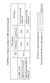
- FIG. 5B shows an example of parameter information (Configuration).
- Parameter information # 1, # 2, and # 3 (Configuration # 1, # 2, and # 3) are parameters of TP1, TP2, and TP3, respectively. It corresponds. Also, the parameter information # 1 to # 3 is notified to the user terminal via higher layer signaling (for example, RRC signaling).
- the CRS pattern includes the number of CRS antenna ports and the shift amount. Thereby, the mapping pattern of CRS can be specified.
- the MBSFN configuration (MBSFN config) corresponds to the MBSFN configuration, and the presence or absence of a CRS pattern in the PDSCH region can be determined from the MBSFN configuration.
- the non-zero power CSI-RS (NZP CSI-RS) is a reference signal that can be used for estimating the desired signal. By notifying the user terminal of the non-zero power CSI-RS pattern (NZP CSI-RS pattern), the CSI-RS The Quasi co-location relationship between RS and DM-RS can be determined.
- Zero power CSI-RS is a reference signal that can be used for interference signal estimation, and PDSCH is not multiplexed. By notifying the user terminal of a zero power CSI-RS pattern (ZP CSI-RS pattern), rate matching can be performed appropriately.
- the PDSCH starting symbol (PDSCH starting symbol) is a parameter indicating a head symbol in which the PDSCH is arranged. Thereby, the user terminal can specify the head symbol of the PDSCH of the adjacent cell. Note that the parameter information in FIG. 5 is an example, and the present invention is not limited to this.
- the identifier indicating each parameter information (PDSCH RE Mapping and Quasi-co-location Configuration) shown in FIG. 5B may be called PQI (PDSCH RE Mapping and Quasi-co-location Indicator).
- the PQI is included in downlink control information (DCI) and notified to the user terminal. For example, when data is transmitted from TP0 to the user terminal in subframe # 1 as described above, the user terminal is notified by downlink control information so that parameter information # 1 is applied. For example, when the relationship between the parameter information and the PQI is shown in FIG. 4, the PQI set in the DCI is “00”.
- DCI format 2D downlink control information
- the DCI format 2D is also being studied as a DCI format used for the CoMP transmission mode (TM10).
- TM10 CoMP transmission mode
- it is considered to set four sets of parameter information for each CC by using the DCI format 2D.
- the PQI when four types of parameter information are set, the PQI can be represented by 2 bits.
- a method of adding 1 bit to be newly added and an information element (for example, scrambling identity) of an existing DCI format to obtain a 2-bit PQI, or a method of newly adding 2 bits can be applied.
- the number of bits of PQI depends on the number of parameter information. When four types are set as shown in FIG. 4 (Configuration # 1- # 4), the number of bits required for PQI is two. . In the present embodiment, the number of bits for PQI is not limited to 2 bits. For example, when eight types of parameter information are set, the number of bits for PQI can be 3 bits. In this case as well, the above method (a method of newly adding 1 bit or 2 bits + a method of combining with a predetermined information element or a method of newly adding 3 bits) can be applied as PQI.
- carrier aggregation CA
- PUSCH downlink control information transmitted at transmission point TP1 (cell 1) is transmitted to another transmission point TP0 (cell 0).
- Can be multiplexed and transmitted (cross-carrier scheduling).
- CIF for setting a carrier identifier (CI: Carrier Indicator) (or CC identifier (CC Indicator)) to identify which transmission point PDSCH corresponds to each downlink control information.
- the DCI format with (Carrier Indicator field) added is applied (see FIGS. 6B and 6C).
- FIG. 6C shows a table (hereinafter also referred to as “table 1”) that defines the relationship between CIF bits and CC identifiers.
- CIF is a field that represents a carrier identifier (CI).
- CI carrier identifier
- a user terminal uses a cell (CC) in which a PDSCH to be demodulated is multiplexed based on bits specified in CIF. Can be specified.
- the number of CIF bits is determined in consideration of the number of CCs to which CA is applied. When CA of up to 5 CCs is assumed, the number of CIF bits is 3 bits.
- the network controls whether to add 3 bits for CIF to DCI according to the presence / absence of cross-carrier scheduling, and transmits information on the presence / absence of DCI setting to higher layer signaling (for example, , RRC signaling) to the user terminal.
- higher layer signaling for example, , RRC signaling
- Boolean indicating whether or not 3-bit CIF exists in DCI can be defined as the basic data type
- the present inventors have focused on using CIF when notifying predetermined parameter information by setting PQI in downlink control information (DCI).
- DCI downlink control information
- DCI downlink control information
- a bit field for PQI is newly set in DCI (for example, DCI format 2D).
- DCI format 2D there are a method of adding one new bit for PQI and combining it with an information element of an existing DCI format (for example, scrambling identity (Nscid)), and a method of adding two new bits for PQI.
- a DCI format 2D can be obtained by adding a PQI bit to the existing DCI format 2C.
- CIF is added to downlink control information (cif_Presence: True)
- the CIF bit is used as an identifier of parameter information (reusing CIF only (Alt. 1)), a bit field (CIF) for CC identifier, It is conceivable to set each bit field for PQI (CIF + PQI (Alt. 2)).
- the CIF is used as the original CC identifier, and a part of the CIF is used as the parameter information identifier, or the CIF is not used as the original CC identifier but as an identifier indicating the parameter information. Use. That is, part or all of the CIF is used as a substitute for the PQI.
- up to four types of parameter information are defined for each CC using a 3-bit CIF, up to two CCs using CoMP can be supported.
- the present inventors have made a signaling method of an identifier indicating parameter information based on a communication form with a user terminal (CoMP transmission presence / absence and transmission form, number of CCs to which CoMP is applied, CIF setting presence / absence, etc.) Inspired to control. Specifically, the network (wireless base station) side controls whether or not to set the bit field for PQI based on the communication form with the user terminal, and determines whether or not the bit field for PQI is set. Signaling to.
- Pqi-Presence is used as a Boolean (a basic data type having two values “true” and “false”) indicating whether or not a bit field for 1-bit or 2-bit PQI exists in DCI. "Is newly defined, and it has been found that the user terminal is notified of the presence / absence of PQI setting by RRC signaling.
- the user terminal can appropriately determine the content indicated by the CIF on the user terminal side.
- the idea was to select a predetermined table based on a predetermined condition from a plurality of tables.
- parameter information may not be required in the user terminal if the CoMP format is CS / CB. Also in this case, as in the case where CoMP is not applied, information (pqi_Presence: False) that does not set the PQI is notified to the user terminal by higher layer signaling (for example, RRC signaling).
- higher layer signaling for example, RRC signaling
- CS / CB CoMP can also set up four types of parameter information and notify the user terminal by higher layer signaling when considering cooperation with DPS or JT CoMP.
- a field for PQI is set (pqi_Presence: True).
- PQI is set in some CCs (for example, CC1) among a plurality of CCs performing CoMP, and PQI is not set in other CCs (for example, CC2). Is also possible.
- the CIF bit is used as an identifier of parameter information (Alt.1, reuse CIF), and the number of CCs is
- a CC identifier bit field (CIF) and a PQI bit field are set (Alt.2, CIF + PQI), respectively.
- an identifier indicating parameter information can be defined for DCI using CIF. That is, since CIF can be used for PQI, control is performed so as not to set a bit field for PQI in DCI (for example, DCI format 2D). In this case, information (pqi_Presence: False) that does not set the PQI is notified from the radio base station to the user terminal by higher layer signaling (for example, RRC signaling).
- higher layer signaling for example, RRC signaling
- control is performed so that PQI is set in DCI.
- information (pqi_Presence: True) for setting the PQI is notified from the radio base station to the user terminal by higher layer signaling (for example, RRC signaling).
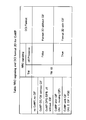
- FIG. 9 is a table that defines the relationship between CIF bits, CC identifiers, and parameter information when CA is performed with five CCs and CoMP is applied with one CC (here, CC0) (hereinafter, “ Table 2 ”).
- parameter information (4 sets) for CC0 can be defined using the CIF free space.
- “001”, “010”, “011”, and “100” in the CIF correspond to CC identifiers of CC1, CC2, CC3, and CC4, respectively, and “000”, “101”, and “110” in the CIF.
- “111” is the identifier of CC0 and corresponds to the parameter information # 1 to # 4 of CC0.
- FIG. 10 is a table (hereinafter referred to as a table) defining the relationship among CIF bits, CC identifiers, and parameter information when CA is performed with two CCs and CoMP is applied with two CCs (here, CC0 and CC1). , Also referred to as “Table 3”).
- parameter information for example, 4 sets ⁇ 2
- CC0 and CC1 when there are two CCs to which CoMP is applied, parameter information (for example, 4 sets ⁇ 2) for CC0 and CC1 can be respectively defined using CIF.
- CIF parameter information # 1 to # 4 of CC0, respectively, and “100”, “101”, “110”, A case where “111” corresponds to parameter information # 1 to # 4 of CC1 is shown.
- CIF is set in downlink control information (cif_Presence: True)
- CIF is used.
- Parameter information of each CC can be set. Also in this case, since it is not necessary to add a new bit field to the downlink control information even when the parameter information is notified, the number of bits of the downlink control information can be saved.
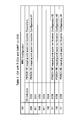
- FIG. 11 shows a case where CA is performed with five CCs and CoMP is applied with three or more CCs (here, three of CC0, CC1, and CC2), CIF bits, PQI bits, CC identifiers, A table (hereinafter also referred to as “table 4”) that defines the relationship with the parameter information is shown.
- the parameter information (4 sets ⁇ 3) for each CC can be defined using CIF bits (for example, 3 bits) and PQI bits (2 bits).
- CIF bits for example, 3 bits
- PQI bits 2 bits.
- “000”, “001”, “010”, “011”, “100” in the CIF correspond to CC0, CC1, CC2, CC3, CC4, respectively, and “00”, “01”, “10” and “11” indicate cases corresponding to parameter information # 1 to # 4 of each CC, respectively.
- the third mode In the third mode, a case where the presence / absence of setting of a field for PQI for DCI (pqi_Presence: True / False) is controlled according to the number of CSI processes (CSI process number) will be described with reference to FIG.
- the number of CSI processes refers to the number of CSI that the user terminal can feed back in one subframe.
- the number of CSI processes is controlled for each CC, and the higher the performance of the user terminal, the higher the number of CSI processes.
- control is performed so that the bit field for PQI is newly set to DCI (for example, DCI format 2D) (pqi_Presence: True), and the user terminal (See FIG. 12B).
- DCI for example, DCI format 2D
- pqi_Presence True
- the number of bits of downlink control information is appropriately controlled according to the communication mode of the user terminal. be able to. Accordingly, it is possible to suppress an increase in overhead of DCI and to appropriately notify the parameter information of each CC to the user terminal.
- the radio base station (transmission point) is based on the communication form with the user terminal (for example, at least one of application / non-application of CoMP, transmission form of CoMP, CC number of CoMP, and presence / absence of CIF setting).
- the presence / absence of field setting for PQI is controlled.
- the user terminal obtains predetermined parameter information based on parameter information notified from the radio base station, downlink control information (for example, DCI format 2D), and information on presence / absence of PQI field setting (pqi_Presence: True / False). It is possible to determine and perform reception processing.
- the contents indicated by the CIF may differ depending on the communication form. Specifically, when the CIF bit is used as an identifier representing a predetermined CC as usual (Table 1 in FIG. 6C) and when the CIF bit is used as an identifier for parameter information (for PQI) (reusing CIF, There are a table 2 in FIG. 9 and a table 3 in FIG. 10) and a case where CIF and PQI are set and used (CIF + PQI, table 4 in FIG. 11).
- the CIF when CoMP is not applied as a communication mode between the user terminal and the radio base station (CA only), the CIF is used as an identifier indicating only a predetermined CC (Table 1).
- CIF when CoMP is applied in two or less CCs as a communication mode between a user terminal and a radio base station, CIF is used as an identifier of CoMP CC parameter information (reusing CIF).
- the CIF When CoMP is applied in three or more CCs, the CIF is used as a CC identifier and is used as an identifier for parameter information of each CC in combination with PQI (using CIF + PQI).
- the user terminal since the contents indicated by the CIF in the tables corresponding to the respective communication modes are different, the user terminal indicates what the CIF included in the received downlink control signal represents (for example, in the tables 1 to 4). It is necessary to perform a reception process after determining which content corresponds to.
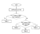
- the user terminal selects a predetermined table based on the presence / absence of PQI setting, the number of CSI processes, the transmission mode (TM), or the PDSCH resource mapping state (parameter information) notified by RRC. Receive processing.
- the user terminal indicates a predetermined table from the four types of tables, the table 1 in FIG. 6C, the table 2 in FIG. 9, the table 3 in FIG. 10, and the table 4 in FIG.
- the contents of these tables are examples, and the number and contents of tables used by the user terminal are not limited to this.
- the user terminal uses Table 4 in FIG. 11 (see FIG. 13A).
- the CIF corresponds to the CC identifier and is used as an identifier indicating parameter information of each cell by combining with the PQI.
- the user terminal uses any one of the tables 1 to 3 based on whether or not CoMP is applied, the number of CoMP CCs, and the like. Note that the presence / absence of PQI setting can be notified from the radio base station to the user terminal by RRC signaling.
- the transmission mode is not the transmission mode (TM10) defined for CoMP
- the CIF is used only as a CC identifier as usual, and selects the table 1 ( (See FIG. 13B).
- the transmission mode is the transmission mode (TM10) defined for CoMP
- one of the tables 2 to 4 is used based on the number of CoMP CCs and the like.
- the user terminal has only 0 or 1 for PDSCH resource mapping state (parameter information) for each CC
- Table 1 is selected (see FIG. 15).
- the parameter information is 2 or more for each CC
- a table can be appropriately selected according to the number of CCs. For example, if there is one CC having two or more parameter information, select table 2, select table 3 if there are two CCs, and select table 4 if there are three or more CCs. Can do.
- the user terminal selects a table in which the correspondence between the CIF and the parameter information is defined based on a predetermined condition. As a result, the reception process can be appropriately performed.
- CIF When CIF is added to downlink control information (cif_Presence: True), use CIF bit as parameter information identifier (reusing CIF only (Alt.1)), CC identifier bit field (CIF) and PQI Each bit field can be set (CIF + PQI (Alt. 2)).
- DCI format 2D is described as an example of the downlink control information format, but the present embodiment is not limited to this.
- PQI may be configured (CIF + PQI) or CIF It may be used as a parameter information identifier (used for PQI) (reusing CIF).
- the radio base station controls the presence / absence of setting for PQI for DCI (pqi_Presence: True / False) to the user terminal. It can be set as the structure to notify.
- Format 2D is replaced with other Format (for example, DCI format 0, 1, 1A, 1B, 1D, 2, 2A, 2B, 2C, 4 ) Can be applied.
- FIG. 17 is a schematic configuration diagram of a radio communication system according to the present embodiment.
- the radio communication system shown in FIG. 17 is a system including, for example, an LTE system or SUPER 3G.
- carrier aggregation in which a plurality of basic frequency blocks (component carriers) with the system bandwidth of the LTE system as one unit is integrated is applied.
- this radio communication system may be called IMT-Advanced, or may be called 4G, FRA (Future Radio Access).
- the radio communication system 1 shown in FIG. 17 includes a radio base station 11 that forms a macro cell C1, and radio base stations 12a and 12b that are arranged in the macro cell C1 and form a small cell C2 that is narrower than the macro cell C1. . Moreover, the user terminal 20 is arrange
- Communication between the user terminal 20 and the radio base station 11 is performed using a carrier having a relatively low frequency band (for example, 2 GHz) and a wide bandwidth (referred to as an existing carrier or a legacy carrier).
- a carrier with a narrow bandwidth in a relatively high frequency band for example, 3.5 GHz
- the same carrier may be used.
- the wireless base station 11 and each wireless base station 12 are wired or wirelessly connected.
- the radio base station 11 and each radio base station 12 are connected to the higher station apparatus 30 and connected to the core network 40 via the higher station apparatus 30.
- the upper station device 30 includes, for example, an access gateway device, a radio network controller (RNC), a mobility management entity (MME), and the like, but is not limited thereto. Further, each radio base station 12 may be connected to a higher station apparatus via the radio base station 11.
- RNC radio network controller
- MME mobility management entity
- the radio base station 11 is a radio base station having a relatively wide coverage, and may be called an eNodeB, a radio base station apparatus, a transmission point, or the like.
- the radio base station 12 is a radio base station having local coverage, and may be called a pico base station, a femto base station, a Home eNodeB, an RRH (Remote Radio Head), a micro base station, a transmission point, or the like. Good.
- RRH Remote Radio Head
- Each user terminal 20 is a terminal that supports various communication schemes such as LTE and LTE-A, and may include not only a mobile communication terminal but also a fixed communication terminal.
- OFDMA Orthogonal Frequency Division Multiple Access
- SC-FDMA Single Carrier Frequency Division Multiple Access
- OFDMA is a multi-carrier transmission scheme that performs communication by dividing a frequency band into a plurality of narrow frequency bands (subcarriers) and mapping data to each subcarrier.
- SC-FDMA is a single-carrier transmission scheme that reduces interference between terminals by dividing the system bandwidth into bands consisting of one or continuous resource blocks for each terminal and using a plurality of terminals with mutually different bands. is there.
- the downlink communication channel includes a PDSCH (Physical Downlink Shared Channel) shared by each user terminal 20 and a downlink L1 / L2 control channel (PDCCH, PCFICH, PHICH, extended PDCCH).
- PDSCH Physical Downlink Shared Channel
- PHICH Physical Hybrid-ARQ Indicator Channel
- PDCCH Physical Downlink Control Channel
- the number of OFDM symbols used for PDCCH is transmitted by PCFICH (Physical Control Format Indicator Channel).
- the HARQ ACK / NACK for PUSCH is transmitted by PHICH (Physical Hybrid-ARQ Indicator Channel).
- PDSCH and PUSCH scheduling information and the like may be transmitted by an extended PDCCH (also called Enhanced Physical Downlink Control Channel, ePDCCH, E-PDCCH, FDM type PDCCH, etc.).
- extended PDCCH also called Enhanced Physical Downlink Control Channel, ePDCCH, E-PDCCH, FDM type PDCCH, etc.
- This enhanced PDCCH enhanced downlink control channel
- PDSCH downlink shared data channel
- the uplink communication channel includes a PUSCH (Physical Uplink Shared Channel) as an uplink data channel shared by each user terminal 20 and a PUCCH (Physical Uplink Control Channel) as an uplink control channel.
- PUSCH Physical Uplink Shared Channel
- PUCCH Physical Uplink Control Channel
- User data and higher control information are transmitted by this PUSCH.
- downlink radio quality information CQI: Channel Quality Indicator
- ACK / NACK and the like are transmitted by PUCCH.
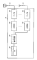
- FIG. 18 is an overall configuration diagram of the radio base station 10 (including the radio base stations 11 and 12) according to the present embodiment.
- the radio base station 10 includes a plurality of transmission / reception antennas 101 for MIMO transmission, an amplifier unit 102, a transmission / reception unit 103, a baseband signal processing unit 104, a call processing unit 105, and a transmission path interface 106. Yes.
- User data transmitted from the radio base station 10 to the user terminal 20 via the downlink is input from the higher station apparatus 30 to the baseband signal processing unit 104 via the transmission path interface 106.
- the baseband signal processing unit 104 performs PDCP layer processing, user data division / combination, RLC layer transmission processing such as RLC (Radio Link Control) retransmission control transmission processing, MAC (Medium Access Control) retransmission control, for example, HARQ transmission processing, scheduling, transmission format selection, channel coding, inverse fast Fourier transform (IFFT) processing, and precoding processing are performed and transferred to each transceiver 103.
- RLC layer transmission processing such as RLC (Radio Link Control) retransmission control transmission processing, MAC (Medium Access Control) retransmission control, for example, HARQ transmission processing, scheduling, transmission format selection, channel coding, inverse fast Fourier transform (IFFT) processing, and precoding processing are performed and transferred to each transceiver 103.
- HARQ transmission processing scheduling, transmission format selection, channel coding, inverse fast Fourier transform (IFFT) processing, and precoding processing are performed and transferred to each transceiver 103.
- IFFT inverse fast Fourier transform
- the baseband signal processing unit 104 notifies the control information for communication in the cell to the user terminal 20 through the broadcast channel.
- the information for communication in the cell includes, for example, the system bandwidth in the uplink or the downlink.
- Each transmission / reception unit 103 converts the baseband signal output by precoding from the baseband signal processing unit 104 for each antenna to a radio frequency band.
- the amplifier unit 102 amplifies the frequency-converted radio frequency signal and transmits the amplified signal using the transmission / reception antenna 101.
- the transmission / reception unit 103 transmits parameter information (PDSCH RE Mapping and Quasi-co-location Configuration), CIF and PQI setting information (cif_Presence, pqi_Presence), downlink control information (DCI), and the like to the user terminal. Functions as a transmission unit.
- radio frequency signals received by the respective transmission / reception antennas 101 are amplified by the amplifier units 102 and frequency-converted by the respective transmission / reception units 103. It is converted into a baseband signal and input to the baseband signal processing unit 104.
- the baseband signal processing unit 104 performs FFT processing, IDFT processing, error correction decoding, MAC retransmission control reception processing, RLC layer, and PDCP layer reception processing on user data included in the input baseband signal.
- the data is transferred to the higher station apparatus 30 via the transmission path interface 106.
- the call processing unit 105 performs call processing such as communication channel setting and release, status management of the radio base station 10, and radio resource management.
- FIG. 19 is an overall configuration diagram of the user terminal 20 according to the present embodiment.
- the user terminal 20 includes a plurality of transmission / reception antennas 201 for MIMO transmission, an amplifier unit 202, a transmission / reception unit (reception unit) 203, a baseband signal processing unit 204, and an application unit 205.
- radio frequency signals received by a plurality of transmission / reception antennas 201 are each amplified by an amplifier unit 202, converted in frequency by a transmission / reception unit 203, and converted into a baseband signal.
- the baseband signal is subjected to FFT processing, error correction decoding, retransmission control reception processing, and the like by the baseband signal processing unit 204.
- downlink user data is transferred to the application unit 205.
- the application unit 205 performs processing related to layers higher than the physical layer and the MAC layer. Also, broadcast information in the downlink data is also transferred to the application unit 205.
- uplink user data is input from the application unit 205 to the baseband signal processing unit 204.
- transmission processing for retransmission control H-ARQ (Hybrid ARQ)
- channel coding precoding
- DFT processing IFFT processing
- the like are performed and transferred to each transmission / reception unit 203.
- the transmission / reception unit 203 converts the baseband signal output from the baseband signal processing unit 204 into a radio frequency band.
- the amplifier unit 202 amplifies the frequency-converted radio frequency signal and transmits the amplified signal using the transmitting / receiving antenna 201.
- the transmission / reception unit 203 receives parameter information (PDSCH RE Mapping and Quasi-co-location Configuration), CIF and PQI setting information (cif_Presence, pqi_Presence), downlink control information (DCI), etc. notified from the radio base station It functions as a part.
- parameter information PDSCH RE Mapping and Quasi-co-location Configuration
- CIF and PQI setting information cif_Presence, pqi_Presence
- DCI downlink control information
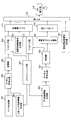
- FIG. 20 is a functional configuration diagram of the baseband signal processing unit 104 and some upper layers included in the radio base station 10 according to the present embodiment. 20 mainly shows a functional configuration for downlink (transmission), the radio base station 10 may include a functional configuration for uplink (reception).
- the radio base station 10 includes an upper layer control information generation unit 300, a data generation unit 301, a channel encoding unit 302, a modulation unit 303, a mapping unit 304, a downlink control information generation unit 305, a channel encoding.
- the higher layer control information generation unit 300 generates higher layer control information for each user terminal 20.
- the higher layer control information is control information for higher layer signaling (for example, RRC signaling), for example, parameter information (PDSCH RE Mapping and Quasi-co-location Configuration), CIF and PQI setting information (cif_Presence, pqi_Presence).
- the data generation unit 301 generates downlink user data for each user terminal 20.
- the downlink user data generated by the data generation unit 301 and the higher layer control information generated by the higher layer control information generation unit 300 are input to the channel coding unit 302 as downlink data transmitted on the PDSCH.
- the channel coding unit 302 performs channel coding on the downlink data for each user terminal 20 according to a coding rate determined based on feedback information from each user terminal 20.
- the modulation unit 303 modulates the channel-coded downlink data according to a modulation scheme determined based on feedback information from each user terminal 20.
- the mapping unit 304 maps the modulated downlink data according to the instruction from the scheduling unit 317.
- the downlink control information generation unit 305 generates downlink control information (DCI) for each user terminal 20.
- the downlink control information includes PDSCH allocation information (DL assisting), PUSCH allocation information (UL grant), and the like.
- the downlink control information generation unit 305 generates downlink control information including an identifier indicating parameter information using a predetermined DCI format (for example, DCI format 2D) according to the communication form with the user terminal.
- the downlink control information generation unit 305 when the number of CCs when applying CoMP is equal to or less than a predetermined number, the downlink control information generation unit 305 generates downlink control information using the CIF bit as an identifier of parameter information (Alt.1, reusing CIF). Also, when the number of CCs is greater than a predetermined number, the downlink control information generation unit 305 sets the CC identifier bit field (CIF) and the PQI bit field, respectively, and generates downlink control information (Alt. 2, CIF + PQI).
- CIF CC identifier bit field
- PQI PQI bit field
- the downlink control information generated by the downlink control information generation unit 305 is input to the channel coding unit 307 as downlink control information transmitted on the PDCCH or the extended PDCCH.
- the channel coding unit 307 performs channel coding on the input downlink control information according to the coding rate instructed from the scheduling unit 317 described later.
- Modulation section 308 modulates the channel-coded downlink control information according to the modulation scheme instructed from scheduling section 317.
- downlink control information transmitted on the PDCCH is input from the modulation unit 308 to the control channel multiplexing unit 309 and multiplexed.
- the downlink control information multiplexed by the control channel multiplexing unit 309 is interleaved by the interleaving unit 310.
- the interleaved downlink control information is input to the IFFT unit 312 together with the measurement reference signals (CSI-RS, CRS, etc.) generated by the measurement reference signal generation unit 311.
- downlink control information transmitted on the extended PDCCH is input from the modulation unit 308 to the mapping unit 313.
- the mapping unit 313 maps the downlink control information according to an instruction from the scheduling unit 317 described later.
- the mapped downlink control information includes downlink data transmitted on the PDSCH (that is, downlink data mapped by the mapping unit 304), and a demodulation reference signal (DM-RS) generated by the demodulation reference signal generation unit 314. At the same time, it is input to the weight multiplier 315.
- Weight multiplying section 315 multiplies downlink data transmitted by PDCSH, downlink control information transmitted by enhanced PDCCH, and a demodulation reference signal by a precoding weight specific to user terminal 20, and performs precoding.
- the precoded transmission data is input to the IFFT unit 312 and converted from a frequency domain signal to a time-series signal by inverse fast Fourier transform.
- a cyclic prefix (CP) functioning as a guard interval is inserted by the CP insertion unit 316 into the output signal from the IFFT unit 312 and output to the transmission / reception unit 103.
- CP cyclic prefix
- the scheduling unit 317 performs scheduling of downlink user data transmitted on the PDSCH, downlink control information transmitted on the enhanced PDCCH, and downlink control information transmitted on the PDCCH.
- the scheduling unit 317 includes instruction information from the higher station apparatus 30 (for example, information related to a communication form with the user terminal), feedback information from each user terminal 20 (for example, CQI (Channel Quality Indicator), RI Based on CSI (Channel State Information) including (Rank Indicator) etc., radio resources are allocated.
- the scheduling unit 317 performs PQI and / or PQI based on the communication mode in the user terminal (for example, at least one of CoMP application status, CoMP transmission mode, CoMP CC count, and CIF setting status). It functions as a control unit that controls whether CIF is set. Also, the scheduling unit (control unit) 317 instructs the upper layer control information generation unit 300 to set PQI and CIF, and to generate parameter information. Further, it is possible to instruct the downlink control information generation unit 305 to specify the identifier of the parameter information included in the downlink control information.
- the higher layer control information generation unit 300 generates parameter information, CIF and PQI setting information (cif_Presence, pqi_Presence), and the like. These pieces of information are notified to the user terminal 20 by higher layer signaling (for example, RRC signaling).
- higher layer signaling for example, RRC signaling
- FIG. 21 is a functional configuration diagram of the baseband signal processing unit 204 included in the user terminal 20.
- the user terminal 20 includes, as a downlink (reception) functional configuration, a CP removal unit 401, an FFT unit 402, a demapping unit 403, a deinterleaving unit 404, a PDCCH demodulation unit 405, a CIF determination unit 406, a PDSCH demodulation unit 407, A channel estimation unit 408 is provided.
- the cyclic prefix (CP) is removed from the downlink signal received as reception data from the radio base station 10 by the CP removal unit 401.
- the downlink signal from which the CP is removed is input to the FFT unit 402.
- the FFT unit 402 performs fast Fourier transform (FFT) on the downlink signal to convert the signal in the time domain to the signal in the frequency domain, and inputs the signal to the demapping unit 403.
- the demapping unit 403 demaps the downlink signal. Note that the demapping process by the demapping unit 403 is performed based on higher layer control information input from the application unit 205.
- the downlink control information output from the demapping unit 403 is deinterleaved by the deinterleaving unit 404.
- the PDCCH demodulation unit 405 performs blind decoding, demodulation, channel decoding, and the like of downlink control information (DCI) output from the deinterleaving unit 404 based on a channel estimation result by a channel estimation unit 408 described later.
- DCI downlink control information
- the CIF determination unit (selection unit) 406 selects a predetermined table from a plurality of tables (for example, tables 1 to 4) in which the contents indicated by the CIF bit are defined. Select. For example, the CIF determination unit 406 performs predetermined processing based on at least one of the presence / absence of a bit field for PQI (pqi_Presence: True / False), the transmission mode, the number of CSI processes, and the number of PDSCH resource mapping states (parameter information). Can be selected (FIGS. 13 to 15 above).
- the user terminal determines parameter information (PDSCH RE Mapping and Quasi-co-location Configuration) and performs reception processing.
- PDSCH RE Mapping and Quasi-co-location Configuration parameters information
- the PDSCH demodulation unit 407 performs demodulation, channel decoding, and the like of downlink data output from the demapping unit 403 based on the channel estimation result by the channel estimation unit 408. Specifically, the PDSCH demodulator 407 demodulates the PDSCH assigned to the terminal based on the downlink control information demodulated by the PDCCH demodulator 405, and downloads downlink data (downlink user data and higher layer control addressed to the terminal). Information).
- the channel estimation unit 408 performs channel estimation using a demodulation reference signal (DM-RS), a measurement reference signal (CRS, CSI-RS), and the like.
- Channel estimation section 408 outputs a channel estimation result based on measurement reference signals (CRS, CSI-RS) to PDCCH demodulation section 405.
- channel estimation section 408 outputs the channel estimation result based on the demodulation reference signal (DM-RS) to PDSCH demodulation section 407.
Abstract
ユーザ端末に対して複数の送信ポイントから下りリンク信号を送信する場合であっても、受信処理に必要となる情報をユーザ端末に適切に通知して受信精度の低下を抑制すること。複数の無線基地局と、複数の無線基地局と協調マルチポイント送信可能なユーザ端末と、を備えた無線通信システムであって、無線基地局は、下りリンク信号に関するパラメータ情報を生成する生成部と、特定のパラメータ情報を示す識別子を含む下り制御情報を生成する制御情報生成部と、下り制御情報にパラメータ情報の識別子用のビットフィールドを設定するか否かを制御する制御部と、パラメータ情報の識別子用のビットフィールドの設定有無に関する情報を上位レイヤシグナリングでユーザ端末に通知する送信部と、を有する。
Description
本発明は、セルラーシステム等に適用可能な無線通信方法、無線通信システム、無線基地局及びユーザ端末に関する。
UMTS(Universal Mobile Telecommunications System)ネットワークにおいては、周波数利用効率の向上、データレートの向上を目的として、HSDPA(High Speed Downlink Packet Access)やHSUPA(High Speed Uplink Packet Access)を採用することにより、W-CDMA(Wideband-Code Division Multiple Access)をベースとしたシステムの特徴を最大限に引き出すことが行われている。このUMTSネットワークについては、更なる高速データレート、低遅延などを目的としてLTE(Long Term Evolution)が検討されている(非特許文献1)。
第3世代のシステムは、概して5MHzの固定帯域を用いて、下り回線で最大2Mbps程度の伝送レートを実現できる。一方、LTEのシステムでは、1.4MHz~20MHzの可変帯域を用いて、下り回線で最大300Mbps及び上り回線で75Mbps程度の伝送レートを実現できる。また、UMTSネットワークにおいては、更なる広帯域化及び高速化を目的として、LTEの後継のシステムも検討されている(例えば、LTEアドバンスト(LTE-A))。LTE-Aシステムのシステム帯域は、LTEシステムのシステム帯域を一単位とする少なくとも一つのコンポーネントキャリア(CC:Component Carrier)を含む。このように複数のコンポーネントキャリア(セル)を集めて広帯域化することをキャリアアグリゲーション(CA:Carrier Aggregation)という。
ところで、LTEシステムに対してさらにシステム性能を向上させるための有望な技術の1つとして、セル間直交化がある。例えば、LTE-Aシステムでは、上下リンクとも直交マルチアクセスによりセル内の直交化が実現されている。すなわち、下りリンクでは、周波数領域においてユーザ端末UE(User Equipment)間で直交化されている。一方、セル間はW-CDMAと同様、1セル周波数繰り返しによる干渉ランダム化が基本である。
そこで、3GPP(3rd Generation Partnership Project)では、セル間直交化を実現するための技術として、協調マルチポイント送受信(CoMP:Coordinated Multi-Point transmission/reception)技術が検討されている。このCoMP送受信では、1つあるいは複数のユーザ端末UEに対して複数のセルが協調して送受信の信号処理を行う。例えば、下りリンクでは、プリコーディングを適用する複数セル同時送信、協調スケジューリング/ビームフォーミングなどが検討されている。これらのCoMP送受信技術の適用により、特にセル端に位置するユーザ端末UEのスループット特性の改善が期待される。
3GPP, TR25.912 (V7.1.0), "Feasibility study for Evolved UTRA and UTRAN", Sept. 2006
LTE Rel.10までは、ユーザ端末は下りリンク信号が単一の無線基地局から送信されていると想定して受信処理を行えばよかった。しかしながら、Rel.11からは、上述したCoMP技術等の導入に伴い、下りリンク信号が複数の送信ポイント(transmission point)からユーザ端末に送信される送信形態がある。
複数の送信ポイント(無線基地局)から下りリンク信号が送信される場合、ユーザ端末はデータ領域(PDSCH:Physical Downlink Shared Channel)が割当てられるリソース(RE)を特定するためにレートマッチングを行う必要がある。例えば、ユーザ端末は、各送信ポイントから送信される下り制御信号(例えば、PDCCH信号)や参照信号(例えば、CRS、CSI-RS等)のマッピングパターンを考慮してレートマッチングを行う必要がある。
また、複数の送信ポイント(無線基地局)からユーザ端末に下りリンク信号をそれぞれ送信する場合、ユーザ端末と各送信ポイントとの位置関係等に応じて、各下りリンク信号の特性(受信信号レベル、受信タイミング、周波数オフセット等)が異なる場合がある。このような場合に、ユーザ端末が、従来と同様に下りリンク信号が単一の無線基地局から送信されていると想定してチャネル推定等の受信処理を行うと、受信精度が低下するおそれがある。
このように、ユーザ端末に対して複数の送信ポイントから下りリンク信号を送信する場合、ユーザ端末側で各送信ポイントからそれぞれ送信される下りリンク信号間の対応関係や、各下りリンク信号のマッピングパターンを考慮して受信処理を行う必要がある。この場合、ユーザ端末が適切に受信処理を行うためには、各下りリンク信号間の対応関係や、各下りリンク信号のマッピングパターン等を、ユーザ端末に適切に通知する方法が必要となる。
本発明はかかる点に鑑みてなされたものであり、ユーザ端末に対して複数の送信ポイントから下りリンク信号を送信する場合であっても、受信処理に必要となる情報をユーザ端末に適切に通知して受信精度の低下を抑制できる無線通信方法、無線通信システム、無線基地局及びユーザ端末を提供することを目的とする。
本発明の無線通信システムは、複数の無線基地局と、前記複数の無線基地局と協調マルチポイント送信可能なユーザ端末と、を備えた無線通信システムであって、前記無線基地局は、下りリンク信号に関するパラメータ情報を生成する生成部と、特定のパラメータ情報を示す識別子を含む下り制御情報を生成する制御情報生成部と、前記下り制御情報に前記パラメータ情報の識別子用のビットフィールドを設定するか否かを制御する制御部と、前記パラメータ情報の識別子用のビットフィールドの設定有無に関する情報を上位レイヤシグナリングで前記ユーザ端末に通知する送信部と、を有することを特徴とする。
本発明によれば、ユーザ端末に対して複数の送信ポイントから下りリンク信号を送信する場合であっても、受信処理に必要となる情報をユーザ端末に適切に通知して受信精度の低下を抑制することができる。
以下、本発明の実施の形態について、添付図面を参照して詳細に説明する。
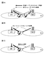
まず、図1を用いて下りリンクの協調マルチポイント(CoMP)送信について説明する。下りリンクのCoMP送信としては、Coordinated Scheduling/Coordinated Beamforming(CS/CB)と、Joint processingとがある。CS/CBは、1つのユーザ端末UEに対して1つの送受信ポイント(又は、無線基地局、セル)からのみ共有データチャネル(PDSCH)を送信する方法であり、図1Aに示すように、他の送受信ポイントからの干渉や他の送受信ポイントへの干渉を考慮して周波数/空間領域における無線リソースの割り当てを行う。
一方、Joint processingは、プリコーディングを適用して複数の送受信ポイントから同時に共有データチャネルを送信する方法であり、図1Bに示すように、1つのユーザ端末UEに対して複数の送受信ポイントから共有データチャネルを送信するJoint transmission(JT)と、図1Cに示すように、瞬時に1つの送受信ポイントを選択し共有データチャネルを送信するDynamic Point Selection(DPS)とがある。また、干渉となる送受信ポイントに対して一定領域のデータ送信を停止するDynamic Point Blanking(DPB)という送信形態もある。
CoMP送信は、セル端に存在するユーザ端末のスループットを改善するために適用する。このため、ユーザ端末がセル端に存在する場合にCoMP送信を適用するように制御する。この場合、無線基地局で、ユーザ端末からのセル毎の品質情報(例えば、RSRP(Reference Signal Received Power))、又はRSRQ(Reference Signal Received Quality)、又はSINR(Signal Interference plus Noise Ratio)等の差を求め、その差が閾値以下である場合、すなわちセル間の品質差が小さい場合には、ユーザ端末がセル端に存在すると判断して、CoMP送信を適用する。
CoMP送受信を適用する環境としては、例えば、無線基地局(無線基地局eNB)に対して光ファイバ等で接続された複数の遠隔無線装置(RRE:Remote Radio Equipment)とを含む構成(RRE構成に基づく集中制御)と、無線基地局(無線基地局eNB)の構成(独立基地局構成に基づく自律分散制御)とがある。
CoMPを適用する場合には、ユーザ端末に対して下りリンク信号(下り制御信号、下りデータ信号、同期信号、参照信号等)が複数の送信ポイント又は特定の送信ポイントから送信される。下りリンク信号を受信したユーザ端末は、例えば、参照信号(セル固有参照信号(CRS:Cell specific Reference Signal)、ユーザ固有の復調用参照信号(DM-RS:Demodulation Reference Signal)、チャネル状態測定用参照信号(CSI-RS:Channel State Information-Reference Signal)等)を用いて受信処理を行う。ユーザ端末が行う受信処理としては、例えば、チャネル推定、同期処理、復調処理、フィードバック情報(CSI)生成処理等の信号処理等がある。
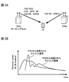
しかし、ユーザ端末に対して地理的に異なる複数の送信ポイントから下りリンク信号が送信される場合、各送信ポイントから送信される下りリンク信号の受信信号レベルや受信タイミング等が異なる場合がある(図2A、B参照)。ユーザ端末は、受信した下りリンク信号(例えば、異なるアンテナポート(AP:Antenna Port)に割当てられる参照信号)がそれぞれどの送信ポイントから送信された信号であるか把握できない。ユーザ端末が受信した全ての参照信号を用いてチャネル推定や復調処理等を行う場合には、受信精度が低下するおそれがある。
そのため、各送信ポイントから送信される参照信号を用いて受信処理を行う場合、ユーザ端末が各送信ポイントの地理的位置(各送信ポイントから送信される下りリンク信号の伝搬路特性)を考慮して、受信処理を行うことが望ましい。そこで、異なるアンテナポート(AP)間で長期的伝搬路特性が同一である場合を「Quasi co-location」(地理的に同一)であると想定し、各下りリンク信号間がQuasi co-locationであるか否かに応じてユーザ端末がそれぞれ異なる受信処理を行うことが検討されている。
長期的伝搬路特性は、遅延スプレッド(Delay spread)、ドップラースプレッド(Doppler spread)、周波数シフト(Frequency shift)、平均受信電力(Average received power)、受信タイミング(Received timing)等を指し、これらの内のいくつか、又は全てが同一である場合にQuasi co-locationであると想定する。Quasi co-locationであるとは、地理的に同一の場合に相当するが必ずしも物理的に近接している場合に限られない。
例えば、地理的に離れた(Quasi co-locationでない)APからそれぞれ送信が行われた場合、ユーザ端末は、地理的に離れたAPから送信が行われたことを認識した上で、Quasi co-locationを想定した場合とは異なる受信処理を行うことができる。具体的には、地理的に離れたAP毎に受信処理(例えば、チャネル推定、同期処理、復調処理、フィードバック情報(CSI)生成処理等の信号処理)をそれぞれ独立して行う。
一例として、地理的に同一(Quasi co-locationである)と判断したAPからCRSが送信され、地理的に離れている(Quasi co-locationでない)と判断したAP#15とAP#16からCSI-RSが送信された場合を想定する(図2A参照)。この場合、ユーザ端末は、CRSを用いて従来と同様に受信処理(measurement)を行う。一方で、ユーザ端末は、CSI-RSについては、AP#15とAP#16に対してそれぞれ独立のチャネル推定を行った後、チャネル品質情報をそれぞれ生成してフィードバックする。
なお、ユーザ端末において、異なるAP間でQuasi co-locationであるかどうかを想定する対象としては、例えば、PSS/SSS、CRS、DM-RS(PDSCH用)、DM-RS(ePDCCH用)、CSI-RS等が挙げられる。
このように、Rel.11からは、ユーザ端末側において、各下りリンク信号間の対応関係(Quasi co-location関係)を考慮して受信処理を行うことが重要となる。
また、CoMP等によりユーザ端末に対して複数の送信ポイントから下りリンク信号が送信される場合、ユーザ端末は各送信ポイントから送信される制御信号や参照信号のマッピングパターン等を考慮してPDSCHが割当てられるリソース(RE)を特定する(レートマッチングする)ことが望ましい。例えば、複数の送信ポイント(TP1とTP2)からユーザ端末に送信を行う場合(例えば、JT CoMP)、ユーザ端末は、TP1とTP2におけるPDCCH、CRS、CSI-RSのマッピングパターン等を考慮してレートマッチングを行うこと好ましい。
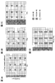
例えば、ユーザ端末が複数の送信ポイント(TP1~TP3)と接続可能に構成されるシステムにおいて、TP1とTP2を用いてCoMP(例えば、JT CoMP)を適用する場合を想定する。この場合、ユーザ端末は、TP1とTP2からそれぞれ送信される制御信号や参照信号等のマッピングパターンを考慮してレートマッチングを行う(図3参照)。なお、図3A~3Cは、TP1~TP3のノーマルサブフレームにおけるマッピングパターンの一例を示し、図3Dは、TP1とTP2から送信される信号を考慮したマッピングパターンに相当する。
TP1とTP2でJT CoMPを適用する場合、図3Dに示すように、下り制御チャネルが割当てられる所定のシンボルより後の無線リソースのうち、CRSがマッピングされるリソース以外の領域にPDSCHがマッピングされる。ユーザ端末は、図3Dのパターンを考慮して受信処理を行うことにより受信処理精度を向上することができる。なお、図3では参照信号としてCRSのみ示しているが、CSI-RSがマッピングされる場合にはCSI-RSも考慮してレートマッチングを行う。
また、図3では、CRSが周波数帯域全体にまたがってマッピングされるノーマルサブフレームを示しているが、サブフレーム構成として、MBSFN(Multimedia Broadcast Multicast service Single Frequency Network)サブフレーム、ニューキャリアタイプ(NCT:New Carrier Type)の適用も検討されている。
MBSFNとは、MBSFNを構成する複数の無線基地局が、同一信号を一斉同期送信することにより、ユーザ端末が各無線基地局から送信された信号をRF(Radio frequency)合成できる方式である。MBSFNサブフレームでは、制御チャネル以外を空白区間(ブランク期間)とし、PDSCH領域にCRSが割当てられないサブフレームである。ニューキャリアタイプ(「Extension carrierタイプ」ともいう)のサブフレームとは、サブフレームの先頭から所定のOFDMシンボル(最大3OFDMシンボル)までの既存PDCCHを持たず、CRSも割当てられないサブフレームである。
例えば、TP1がノーマルサブフレーム、TP2がMBSFNサブフレーム(又は、NCT)である場合、TP2のPDSCH領域にCRSパターンは存在しない。このため、TP1+TP2のレートマッチングパターンはTP1のマッピングパターンと等しくなる。つまり、ユーザ端末は、ノーマルサブフレームを用いるTP1のPDSCH用のREのマッピングパターンのみを考慮してレートマッチングを行うことができる。
このように、ユーザ端末において、複数の送信ポイントから送信されるPDCCH、CRS、CSI-RSのマッピングパターンやサブフレーム構成を考慮してレートマッチングを行うことにより、サービングセルと隣接セルのPDSCHのリソースを特定して受信処理を行うことができる。つまり、Rel.11からは、ユーザ端末が、PDCCH、CRS、CSI-RS等のマッピングパターンやサブフレーム構成を考慮してレートマッチングを行うことが重要となる。
したがって、ユーザ端末が適切に受信処理を行うための情報(Quasi co-location関係や、PDSCHリソースのマッピング情報等)を、ユーザ端末に適切に通知する方法が必要となる。
例えば、コンポーネントキャリア(CC)毎に、PDSCHリソースのマッピング情報(PDSCH RE mapping Parameter)とQuasi co-location情報(Quasi-co-location Configuration Parameter)が規定されたパラメータ情報(PDSCH RE Mapping and Quasi-co-location Configuration)を所定数(例えば、4セット)準備して、ユーザ端末に通知することが検討されている。
具体的には、無線基地局(ネットワーク)側で、ユーザ端末周辺の送信ポイントや通信環境等を考慮して、PDSCHリソースのマッピング情報とQuasi co-location情報を含むパラメータ情報(以下、「パラメータ情報」とも記す)を所定数(例えば、4種類)規定する。そして、当該複数のパラメータ情報を上位レイヤシグナリング(例えば、RRCシグナリング)でユーザ端末に通知する。さらに、4種類のパラメータ情報#1~#4の中から特定のパラメータ情報をユーザ端末に選択させるための指示を下り制御情報(DCI)に含めてユーザ端末にダイナミックに通知することが検討されている(図4参照)。
つまり、図4に示すパラメータ情報#1~#4(PDSCH RE Mapping and Quasi-co-location Configuration #1-#4)が上位レイヤシグナリングでユーザ端末に通知されると共に、各パラメータ情報に対応するビット情報(“00”、“01”、“10”又は“11”)が下り制御情報(DCI)に含められてユーザ端末に通知される。
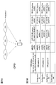
PDSCHリソースのマッピング情報とQuasi co-location情報を含むパラメータ情報の一例について、図5を参照して説明する。図5Aは、複数の送受信ポイント(ここでは、TP1、TP2、TP3の3つ)から瞬時に1つの送受信ポイントを選択し共有データチャネルを送信するDPS CoMPを適用する場合を示している。ネットワークは、動的に1つの送信ポイント(無線基地局)を選択して、ユーザ端末にデータ信号を送信する。
例えば、図5Aに示すDPS CoMPにおいて、サブフレーム#1で送信ポイントTP1からユーザ端末にデータ信号を送信し、サブフレーム#2で送信ポイントTP2からユーザ端末にデータ信号を送信し、サブフレーム#3で送信ポイントTP3からユーザ端末にデータ信号を送信することができる。
また、図5Bは、パラメータ情報(Configuration)の一例を示しており、パラメータ情報#1、#2、#3(Configuration#1,#2,#3)は、それぞれTP1、TP2、TP3のパラメータに対応している。また、パラメータ情報#1~#3は、上位レイヤシグナリング(例えば、RRCシグナリング)を介してユーザ端末に通知される。
図5において、CRSパターン(CRS pattern)には、CRSのアンテナポート数とシフト量が含まれる。これにより、CRSのマッピングパターンを特定することができる。MBSFN構成(MBSFN config)は、MBSFNの構成に相当し、MBSFN構成からPDSCH領域のCRSパターンの有無を判断することができる。ノンゼロパワーCSI-RS(NZP CSI-RS)は、希望信号推定用に利用可能な参照信号であり、ユーザ端末にノンゼロパワーCSI-RSパターン(NZP CSI-RS pattern)を通知することにより、CSI-RSとDM-RSのQuasi co-location関係を判断することができる。ゼロパワーCSI-RS(ZP CSI-RS)は、干渉信号推定用に利用可能な参照信号でありPDSCHが多重されない。ユーザ端末にゼロパワーCSI-RSパターン(ZP CSI-RS pattern)を通知することにより、レートマッチングを適切に行うことができる。PDSCH開始シンボル(PDSCH starting symbol)は、PDSCHが配置される先頭シンボルを示すパラメータである。これにより、ユーザ端末は隣接セルのPDSCHの先頭シンボルを特定することができる。なお、図5のパラメータ情報は一例であり、これに限られない。
また、図5Bに示した各パラメータ情報(PDSCH RE Mapping and Quasi-co-location Configuration)を示す識別子は、PQI(PDSCH RE Mapping and Quasi-co-location Indicator)と呼ばれることがある。PQIは、下り制御情報(DCI)に含められ、ユーザ端末に通知される。例えば、上述したようにサブフレーム#1でTP0からユーザ端末にデータが送信される場合、ユーザ端末にパラメータ情報#1を適用するように下り制御情報で通知する。例えば、パラメータ情報とPQIの関係が図4に示す場合、DCIに設定されるPQIは“00”となる。
また、PQIを設定する(configure)ための下り制御情報(DCI)として、新たに「DCIフォーマット2D」を設けることが検討されている。また、DCIフォーマット2Dは、CoMP用の送信モード(TM10)に利用するDCIフォーマットとしても検討されている。また、DCIフォーマット2Dを用いることにより、1CC毎に4セットのパラメータ情報を設定することが検討されている。
例えば、図4に示すように、パラメータ情報を4種類設定する場合、PQIは2ビットで表すことができる。この場合、新たに追加する1ビットと既存のDCIフォーマットの情報要素(例えば、Scrambling identity)を組み合わせて2ビットのPQIとする方法、又は、新たに2ビット追加する方法を適用することができる。
なお、PQIのビット数は、パラメータ情報の数に依存し、図4に示すように4種類設定する場合(Configuration #1-#4)には、PQI用に必要となるビット数は2となる。なお、本実施の形態では、PQI用のビット数は2ビットに限られない。例えば、パラメータ情報を8種類設定する場合には、PQI用のビット数を3ビットとすることができる。この場合も、PQIとして上記方法(1ビット又は2ビットを新たに追加+所定の情報要素と組合せる方法、又は3ビットを新たに追加する方法)を適用することができる。
ところで、キャリアアグリゲーション(CA)を適用する場合、例えば、図6A、6Bに示すように、送信ポイントTP1(セル1)で送られるPUSCH用の下り制御情報を、別の送信ポイントTP0(セル0)のPDCCHに多重して送信すること(クロスキャリアスケジューリング)ができる。このとき、各下り制御情報がどちらの送信ポイントのPDSCHに対応する情報であるかを識別するために、キャリア識別子(CI:Carrier Indicator)(又は、CC識別子(CC Indicator))設定するためのCIF(Carrier Indicator field)を付加したDCIフォーマットが適用される(図6B、6C参照)。図6Cは、CIFビットと、CC識別子との関係を規定したテーブル(以下、「テーブル1」とも記す)を示している。
つまり、CIFは、キャリア識別子(CI)を表すフィールドであり、クロスキャリアスケジューリングが行われる場合、ユーザ端末はCIFに規定されるビットに基づいて、復調すべきPDSCHが多重されているセル(CC)を特定することができる。なお、CIFのビット数はCAを適用するCC数を考慮して決められ、5CCまでのCAを想定した場合CIFのビット数は3ビットとなる。
一方で、クロスキャリアスケジューリングを行わない場合には、DCIにCIFを付加しない(CIFを0ビットとする)ことにより、下り制御情報のビット数を削減することができる。このため、ネットワーク(無線基地局)は、クロスキャリアスケジューリングの有無に応じて、CIF用の3ビットをDCIに付加するか否かを制御すると共に、DCIの設定有無に関する情報を上位レイヤシグナリング(例えば、RRCシグナリング)でユーザ端末に通知することができる。
具体的には、クロスキャリアスケジューリング構成の情報要素(Cross Carrier Scheduling Config information elements)において、DCIに3ビットのCIFが存在するか否かを示すBOOLEAN(“true”と“false”の2値を取る基本データ型)として、「cif-Presence」を定義して、RRCシグナリングでユーザ端末に通知することができる。
また、CAのCC数としては現状最大5CCまでサポートされているため、CIFの3ビットの識別子のうち5値必要となるが、残り3値は使用されない。つまり、残りの3値を他の情報に利用することができる。そこで、本発明者らは、下り制御情報(DCI)にPQIを設定して所定のパラメータ情報を通知する場合にCIFを利用することに着目した。
例えば、下り制御情報(DCI)にCIFが付加されない場合(cif_Presence:False)、DCI(例えば、DCIフォーマット2D)にPQI用のビットフィールドを新たに設定する。この場合、上述したようにPQI用に新たに1ビット追加すると共に既存のDCIフォーマットの情報要素(例えば、Scrambling identity(Nscid))と組み合わせる方法と、PQI用に新たに2ビット追加する方法がある。例えば、既存のDCIフォーマット2CにPQI用のビットを追加したフォーマットをDCIフォーマット2Dとすることができる。
一方、下り制御情報にCIFが付加される場合(cif_Presence:True)、CIFビットをパラメータ情報の識別子として利用すること(reusing CIF only(Alt.1))、CC識別子用のビットフィールド(CIF)とPQI用のビットフィールドをそれぞれ設定すること(CIF+PQI(Alt.2))が考えられる。
Alt.1(reusing CIF)の場合、CIFを本来のCC識別子として利用すると共に、CIFの一部をパラメータ情報の識別子として利用する、又はCIFを本来のCC識別子として利用するのでなくパラメータ情報を示す識別子として利用する。つまり、CIFの一部又は全部をPQIの代用とする。また、3ビットのCIFを用いて、CC毎にパラメータ情報を4種類まで定義する場合、CoMPを利用するCCとして最大2つまでサポートすることができる。
Alt.2(CIF+PQI)の場合、CIFを本来のCC識別子として利用すると共に、PQI用のビットフィールドを新たに設定する。この場合、3ビットのCIFと2ビットのPQIを用いて、CC毎にパラメータ情報を4種類まで定義すると、CoMPを利用するCCとして最大5つまでサポートすることができる。なお、PQI用のビットフィールドを追加する場合、PQI用に新たに1ビット追加すると共に既存のDCIフォーマットの情報要素(例えば、Nscid)と組み合わせる方法と、PQI用に新たに2ビット追加する方法を適用することができる。
上述したように本発明者らは、ユーザ端末との通信形態(CoMP送信の有無や送信形態、CoMPを適用するCC数、CIFの設定有無等)に基づいて、パラメータ情報を示す識別子のシグナリング方法を制御することを着想した。具体的には、ネットワーク(無線基地局)側で、ユーザ端末との通信形態に基づいてPQI用のビットフィールドを設定するか否かを制御し、PQI用のビットフィールドの設定の有無をユーザ端末に対してシグナリングする。
また、この場合、DCIにおいて1ビット又は2ビットのPQI用のビットフィールドが存在するか否かを示すBOOLEAN(“true”と“false”の2値を取る基本データ型)として、「pqi-Presence」を新たに定義して、RRCシグナリングでユーザ端末にPQIの設定有無を通知することを見出した。
また、本発明者らは、CIFビットの一部又は全部をパラメータ情報の識別子として利用する場合に、ユーザ端末側でCIFが示す内容を適切に判断できるように、ユーザ端末がCIFビットが示す内容が規定された複数のテーブルの中から所定の条件に基づいて所定のテーブルを選択することを着想した。
以下に、ユーザ端末との通信形態に応じて、PQI用のフィールドの設定有無を制御する場合について説明する。
(第1の態様)
第1の態様では、下り制御情報(DCI)にCIFが設定(configure)されない場合(cif_Presence:False)に、無線基地局が、CoMPの適用有無や、CoMPの形態(CoMP scheme)に応じてDCIに対するPQIの設定有無(pqi_Presence:True/False)を制御する場合について図7を参照して説明する。
第1の態様では、下り制御情報(DCI)にCIFが設定(configure)されない場合(cif_Presence:False)に、無線基地局が、CoMPの適用有無や、CoMPの形態(CoMP scheme)に応じてDCIに対するPQIの設定有無(pqi_Presence:True/False)を制御する場合について図7を参照して説明する。
ユーザ端末に対してCoMPを適用しない場合、ユーザ端末においてPDSCHリソースのマッピング情報とQuasi co-location情報を含むパラメータ情報が必要とならない。そのため、CoMPを適用しない場合には、DCI(例えば、DCIフォーマット2D)にPQIを設定しないように制御すると共に、PQI用のビットフィールドが設定されない情報(pqi_Presence:False)をユーザ端末に上位レイヤシグナリング(例えば、RRCシグナリング)で通知する。
また、ユーザ端末にCoMPを適用する場合であっても、CoMPの形態がCS/CBである場合には、ユーザ端末においてパラメータ情報が必要とならない場合がある。この場合も、CoMPを適用しない場合と同様に、ユーザ端末に対してPQIを設定しない情報(pqi_Presence:False)を上位レイヤシグナリング(例えば、RRCシグナリング)で通知する。
一方で、ユーザ端末に対して、CoMPを適用する場合でユーザ端末においてパラメータ情報が必要となる場合(CS/CB、DPS/DPB又はJT)、DCI(例えば、DCIフォーマット2D)にPQIを設定するように制御する。そして、ユーザ端末に対して、この場合、無線基地局(送信ポイント)からユーザ端末に対して、PQI用のフィールドが設定される情報(pqi_Presence:True)が上位レイヤシグナリング(例えば、RRCシグナリング)で通知する。
なお、CS/CB CoMPにおいてもDPSやJT CoMPとの連携を考慮した場合には、4種類のパラメータ情報を設定して上位レイヤシグナリングでユーザ端末に通知することができる。この場合には、PQI用のフィールドを設定する(pqi_Presence:True)。
また、DCIにPQIを設定する場合、CoMPを行う複数のCCの中で一部のCC(例えば、CC1)においてPQIを設定し、他のCC(例えば、CC2)においてPQIの設定を行わないことも可能である。
このように、CoMPの適用有無や形態に応じて、DCIに対するPQIの設定有無(pqi_Presence:True/False)を制御することにより、PQIが必要な時に限って新たなビットフィールドをDCIに設定することができるため、DCIのリソースを有効に活用することができる。
(第2の態様)
第2の態様では、下り制御情報(DCI)にCIFが設定される場合(cif_Presence:True)に、無線基地局が、CoMP送信を行うCC(セル)の数に応じてDCIに対するPQIの設定有無(pqi_Presence:True/False)、パラメータ情報の通知方法を制御する場合について図8を参照して説明する。
第2の態様では、下り制御情報(DCI)にCIFが設定される場合(cif_Presence:True)に、無線基地局が、CoMP送信を行うCC(セル)の数に応じてDCIに対するPQIの設定有無(pqi_Presence:True/False)、パラメータ情報の通知方法を制御する場合について図8を参照して説明する。
具体的には、ユーザ端末に対してCoMPを適用する際のCC数が所定数以下である場合には、CIFビットをパラメータ情報の識別子として利用し(Alt.1、reusing CIF)、CC数が所定数より多い場合には、CC識別子用のビットフィールド(CIF)とPQI用のビットフィールドをそれぞれ設定する(Alt.2、CIF+PQI)。このように、CC数に応じてPQI用のビットフィールドの設定有無を判断することにより、下り制御情報のオーバーヘッドを低減することができる。
例えば、CoMP及びCAを利用するCCが1つ(4セット)又は2つ(4セット×2)の場合、DCIに対してCIFを利用してパラメータ情報を示す識別子を規定することができる。つまり、CIFをPQI用に利用することができるため、DCI(例えば、DCIフォーマット2D)にPQI用のビットフィールドを設定しないように制御する。この場合、無線基地局からユーザ端末に対して、PQIを設定しない情報(pqi_Presence:False)が上位レイヤシグナリング(例えば、RRCシグナリング)で通知される。
上述以外(CoMP及びCAを利用するCCが3つ以上の場合)、DCIにPQIを設定するように制御する。この場合、無線基地局からユーザ端末に対して、PQIを設定する情報(pqi_Presence:True)が上位レイヤシグナリング(例えば、RRCシグナリング)で通知される。
次に、CoMP送信を行うCC(セル)の数が1つ、2つ、3つの場合において、CIF、PQI、上位レイヤシグナリングで通知されるパラメータ情報との対応関係の一例について、それぞれ図9~11を参照して説明する。
図9は、5つのCCでCAを行うと共に1つのCC(ここでは、CC0)でCoMPを適用する場合に、CIFビットと、CC識別子と、パラメータ情報との関係を規定したテーブル(以下、「テーブル2」とも記す)を示している。
図9に示すように、CoMPを適用するCCが1つである場合、CC0用のパラメータ情報(4セット)をCIFの空きスペースを利用して規定することができる。図9では、CIFにおける“001”、“010”、“011”、“100”がそれぞれCC1、CC2、CC3、CC4のCC識別子に対応し、CIFにおける“000”、“101”、“110”、“111”がCC0の識別子であると共に、CC0のパラメータ情報#1~#4にそれぞれ対応する場合を示している。
このように、下り制御情報にCIFが設定される(cif_Presence:True)場合に、CoMPを行うCC(セル)数が1つである際には、CIFの空きスペースを利用してパラメータ情報を通知することができる。この場合、PQI用のビットフィールドを設定しない(pqi_Presence:False)ように制御する。これにより、パラメータ情報を通知する場合であっても下り制御情報に新たなビットフィールドを追加する必要がないため、下り制御情報のビット数を節約することができる。
図10は、2つのCCでCAを行うと共に2つのCC(ここでは、CC0とCC1)でCoMPを適用する場合に、CIFビットと、CC識別子と、パラメータ情報との関係を規定したテーブル(以下、「テーブル3」とも記す)を示している。
図10に示すように、CoMPを適用するCCが2つの場合、CC0、CC1用のパラメータ情報(例えば、4セット×2)を、CIFを利用してそれぞれ規定することができる。図10では、CIFにおける“000”、“001”、“010”、“011”がCC0のパラメータ情報#1~#4にそれぞれ対応し、CIFにおける“100”、“101”、“110”、“111”がCC1のパラメータ情報#1~#4にそれぞれ対応する場合を示している。
このように、下り制御情報にCIFが設定される(cif_Presence:True)場合に、CoMP送信を行うCC(セル)数、CAを適用するCC数が2つである際には、CIFを利用して各CCのパラメータ情報を設定することができる。この場合も、パラメータ情報を通知する場合であっても下り制御情報に新たなビットフィールドを追加する必要がないため、下り制御情報のビット数を節約することができる。
図11は、5つのCCでCAを行うと共に3つ以上のCC(ここでは、CC0、CC1、CC2の3つ)でCoMPを適用する場合に、CIFビットと、PQIビットと、CC識別子と、パラメータ情報との関係を規定したテーブル(以下、「テーブル4」とも記す)を示している。
図11に示すように、CoMPを適用するCCが3つ以上の場合、PQI用のビットフィールドを設定して、ユーザ端末に各CCのパラメータ情報を通知する。この場合、CIF用のビット(例えば、3ビット)と、PQI用のビット(2ビット)を用いて、各CC用のパラメータ情報(4セット×3)を規定することができる。図11では、CIFにおける“000”、“001”、“010”、“011”、“100”がそれぞれCC0、CC1、CC2、CC3、CC4に対応し、PQIにおける“00”、“01”、“10”、“11”がそれぞれ各CCのパラメータ情報#1~#4に対応する場合を示している。
このように、下り制御情報にCIFが設定される(cif_Presence:True)場合に、CoMP送信を行うCC(セル)数が3つである際には、PQI用のビットフィールドを新たに設定する(pqi_Presence:True)ことにより、ユーザ端末に各CCのパラメータ情報を通知することができる。これにより、ユーザ端末は下り制御情報に基づいて適切に受信処理を行うことが可能となる。
(第3の態様)
第3の態様においては、CSIプロセス数(CSI process number)に応じて、DCIに対するPQI用のフィールドの設定の有無(pqi_Presence:True/False)を制御する場合について図12を参照して説明する。なお、CSIプロセス数とは、ユーザ端末が1サブフレームでフィードバック可能なCSI数を指す。CSIプロセス数はCC毎に制御され、性能が高いユーザ端末ほどCSIプロセス数を高くすることができる。
第3の態様においては、CSIプロセス数(CSI process number)に応じて、DCIに対するPQI用のフィールドの設定の有無(pqi_Presence:True/False)を制御する場合について図12を参照して説明する。なお、CSIプロセス数とは、ユーザ端末が1サブフレームでフィードバック可能なCSI数を指す。CSIプロセス数はCC毎に制御され、性能が高いユーザ端末ほどCSIプロセス数を高くすることができる。
下り制御情報にCIFが付加されない場合(cif_Presence:False)において、CCのCSIプロセス数が1である場合には、ユーザ端末の性能が低くCoMP適用の可能性が低いと考えられる。そのため、ユーザ端末にパラメータ情報の通知が不要であるため、DCI(例えば、DCIフォーマット2D)にPQIを設定しないように制御する(図12A参照)。この場合、無線基地局(送信ポイント)からユーザ端末に対して、PQI用のフィールドを設定しない情報(pqi_Presence:False)が上位レイヤシグナリング(例えば、RRCシグナリング)で通知される。
一方で、CCのCSIプロセス数が2以上である場合には、ユーザ端末に対してCoMPの適用が考えられるため、DCI(例えば、DCIフォーマット2D)にPQI用のビットフィールドを設定するように制御する(図12A参照)。この場合、無線基地局(送信ポイント)からユーザ端末に対して、PQI用のビットフィールドを設定する情報(pqi_Presence:True)が上位レイヤシグナリング(例えば、RRCシグナリング)で通知される。
また、複数のCCの中で一部のCC(例えば、CC1)においてPQIを設定し、他のCC(例えば、CC2)においてPQIの設定を行わないことも可能である。
下り制御情報にCIFが付加される場合(cif_Presence:True)には、CSIプロセスが1より大きい(2以上)CC数に応じて、DCIに対するPQI用のフィールドの設定の有無(pqi_Presence:True/False)を制御する。CSIプロセスが2以上のCC数が2以下の場合には、上記図9、図10に示すようにCIFを利用してパラメータ情報を規定して(pqi_Presence:False)、ユーザ端末に通知することができる(図12B参照)。一方で、CSIプロセスが2以上のCC数が3以上の場合には、PQI用のビットフィールドをDCI(例えば、DCIフォーマット2D)に新たに設定するように制御し(pqi_Presence:True)、ユーザ端末に通知する(図12B参照)。
このように、CCのCSIプロセス数に応じてDCIに対するPQI用のフィールドの付加の有無を制御することにより、ユーザ端末の通信形態に応じて下り制御情報(DCI)のビット数を適切に制御することができる。これにより、DCIのオーバーヘッドの増加を抑制すると共に、ユーザ端末に各CCのパラメータ情報を適切に通知することができる。
(ユーザ端末の動作)
上述したように、無線基地局(送信ポイント)は、ユーザ端末との通信形態(例えば、CoMPの適用有無、CoMPの送信形態、CoMPのCC数、CIFの設定の有無の少なくとも一つ)に基づいて、PQI用のフィールド設定の有無を制御する。一方、ユーザ端末は、無線基地局から通知されるパラメータ情報、下り制御情報(例えば、DCIフォーマット2D)、PQI用フィールド設定有無の情報(pqi_Presence:True/False)に基づいて、所定のパラメータ情報を決定して受信処理を行うことができる。
上述したように、無線基地局(送信ポイント)は、ユーザ端末との通信形態(例えば、CoMPの適用有無、CoMPの送信形態、CoMPのCC数、CIFの設定の有無の少なくとも一つ)に基づいて、PQI用のフィールド設定の有無を制御する。一方、ユーザ端末は、無線基地局から通知されるパラメータ情報、下り制御情報(例えば、DCIフォーマット2D)、PQI用フィールド設定有無の情報(pqi_Presence:True/False)に基づいて、所定のパラメータ情報を決定して受信処理を行うことができる。
一方で、上述したように下り制御情報にCIFが付加される場合(cif_Presence:True)、通信形態に応じてCIFが示す内容が異なる場合がある。具体的には、CIFビットを従来通り所定のCCを表す識別子のみとして利用する場合(図6Cのテーブル1)と、CIFビットをパラメータ情報用の識別子(PQI用)として利用する場合(reusing CIF、図9のテーブル2、図10のテーブル3)と、CIFとPQIを設定して利用する場合(CIF+PQI、図11のテーブル4)と、がある。
例えば、ユーザ端末と無線基地局との通信形態として、CoMPを適用しない(CA only)場合、CIFは所定のCCのみを示す識別子として利用される(テーブル1)。また、ユーザ端末と無線基地局との通信形態として、2つ以下のCCでCoMPを適用する場合、CIFはCoMP CCのパラメータ情報の識別子として利用される(reusing CIF)。また、3つ以上のCCでCoMPを適用する場合、CIFはCC識別子として利用されると共に、PQIと組み合わせて各CCのパラメータ情報の識別子として利用される(using CIF+PQI)。
このように、それぞれの通信形態に対応したテーブルにおいてCIFが示す内容が異なっているため、ユーザ端末は、受信した下り制御信号に含まれるCIFが何を表しているか(例えば、テーブル1~4のいずれの内容に相当するか)を判断して、受信処理を行う必要がある。
そこで、本実施の形態では、ユーザ端末がPQIの設定有無、CSIプロセス数、送信モード(TM)、又はRRCで通知されるPDSCHリソースマッピング状態(パラメータ情報)に基づいて、所定のテーブルを選択して受信処理を行う。
以下に、ユーザ端末におけるテーブルの選択方法について説明する。なお、以下の説明では、図6Cのテーブル1、図9のテーブル2、図10のテーブル3、図11のテーブル4の4種類のテーブルからユーザ端末が所定のテーブルを示す場合について説明する。なお、これらのテーブルの内容は一例であり、ユーザ端末が利用するテーブルの数・内容はこれに限られない。
・PQIの有無(Based on PQI present or not)の場合
例えば、DCIにPQIが設定される場合(pqi_Presence:True)、ユーザ端末は図11のテーブル4を利用する(図13A参照)。この場合、CIFは、CC識別子に対応すると共に、PQIと組み合わせることにより、各セルのパラメータ情報を示す識別子として利用される。
例えば、DCIにPQIが設定される場合(pqi_Presence:True)、ユーザ端末は図11のテーブル4を利用する(図13A参照)。この場合、CIFは、CC識別子に対応すると共に、PQIと組み合わせることにより、各セルのパラメータ情報を示す識別子として利用される。
また、DCIにPQIが設定されない場合(pqi_Presence:False)、ユーザ端末は、CoMPの適用有無、CoMPのCC数等に基づいてテーブル1~3のいずれかを利用する。なお、PQIの設定有無は、無線基地局からRRCシグナリングでユーザ端末に通知することができる。
・送信モード(Based on TM)の場合
ユーザ端末は、送信モードがCoMP用に規定される送信モード(TM10)でない場合に、CIFは従来通りCC識別子としてのみ利用されるためテーブル1を選択する(図13B参照)。一方で、送信モードがCoMP用に規定される送信モード(TM10)である場合には、CoMPのCC数等に基づいてテーブル2~4のいずれかを利用する。
ユーザ端末は、送信モードがCoMP用に規定される送信モード(TM10)でない場合に、CIFは従来通りCC識別子としてのみ利用されるためテーブル1を選択する(図13B参照)。一方で、送信モードがCoMP用に規定される送信モード(TM10)である場合には、CoMPのCC数等に基づいてテーブル2~4のいずれかを利用する。
・CSIプロセス数(Based on CSI process number)の場合
ユーザ端末は、各CCにおけるCSIプロセス数が1である場合、CoMPの適用がないと考えられるため、テーブル1を利用する(図14参照)。一方で、CSIプロセス数が2以上の場合、テーブル2~4のいずれかのテーブルを利用する。
ユーザ端末は、各CCにおけるCSIプロセス数が1である場合、CoMPの適用がないと考えられるため、テーブル1を利用する(図14参照)。一方で、CSIプロセス数が2以上の場合、テーブル2~4のいずれかのテーブルを利用する。
CSIプロセス数が2以上の場合、CS/CB CoMPにおいて4種類のパラメータ情報(4states)が必要となるときには、CoMPを適用するCC数の数に応じて適宜テーブル2~3のいずれかを選択することができる。例えば、2以上のCSIプロセスを有するCCが1つの場合にはテーブル2を選択し、CCが2つの場合にはテーブル3を選択し、CCが3つ以上の場合にはテーブル4を選択することができる(図14A参照)。
CS/CBのCoMPでは、ユーザ端末に対して常にサービング送信ポイントからデータを送信するため、ユーザ端末はサービングセルのパラメータ情報(1state)を把握すればよい。しかし、DPSやJT CoMPとの連携を考慮した場合には、CS/CBにおいても4種類のパラメータ情報を設定することができる。なお、この場合、RRCで通知するパラメータ情報#1~#4は互いに同一とすることができる。また、DCIで通知するパラメータ情報の識別子も、4種類(例えば、図4における“00”、“01”、“10”、“11”)が必要となる。
一方、CSIプロセス数が2以上の場合に、CS/CB CoMPにおいて1種類のパラメータ情報(1state)だけでよい場合には、テーブル2~4のいずれかを選択することができる(図14B参照)。この場合、CS/CBのCoMPと、DPSやJT CoMPとではパラメータ情報が異なるが、ユーザ端末側では区別されない。
・上位レイヤシグナリングで通知されるPDSCHリソースマッピング状態(Based on higher-layer signaling of PDSCH REs mapping states)の場合
ユーザ端末は、各CCに対して、PDSCHリソースマッピング状態(パラメータ情報)が0又は1のみである場合、CoMPの適用がないと考えられるため、テーブル1を選択する(図15参照)。一方で、各CCに対してパラメータ情報が2以上である場合、CCの数に応じて適宜テーブルを選択することができる。例えば、2以上のパラメータ情報を有するCCが1つの場合にはテーブル2を選択し、CCが2つの場合にはテーブル3を選択し、CCが3つ以上の場合にはテーブル4を選択することができる。
ユーザ端末は、各CCに対して、PDSCHリソースマッピング状態(パラメータ情報)が0又は1のみである場合、CoMPの適用がないと考えられるため、テーブル1を選択する(図15参照)。一方で、各CCに対してパラメータ情報が2以上である場合、CCの数に応じて適宜テーブルを選択することができる。例えば、2以上のパラメータ情報を有するCCが1つの場合にはテーブル2を選択し、CCが2つの場合にはテーブル3を選択し、CCが3つ以上の場合にはテーブル4を選択することができる。
このように、下り制御情報に設定されるCIFを利用して、パラメータ情報を通知する場合であっても、ユーザ端末が所定条件に基づいてCIFとパラメータ情報の対応が規定されたテーブルを選択することにより、受信処理を適切に行うことが可能となる。
(他の態様)
なお、上記第1の態様~第3の態様では、無線基地局とユーザ端末との通信形態に応じて、DCI(例えば、DCIフォーマット2D)に対するPQIの設定(configure)を制御する場合を示したが、本実施の形態はこれに限られない。例えば、DCIに対してPQIを常に設定する構成としてもよい(図16参照)。
なお、上記第1の態様~第3の態様では、無線基地局とユーザ端末との通信形態に応じて、DCI(例えば、DCIフォーマット2D)に対するPQIの設定(configure)を制御する場合を示したが、本実施の形態はこれに限られない。例えば、DCIに対してPQIを常に設定する構成としてもよい(図16参照)。
下り制御情報にCIFが付加される場合(cif_Presence:True)、CIFビットをパラメータ情報の識別子として利用すること(reusing CIF only(Alt.1))、CC識別子用のビットフィールド(CIF)とPQI用のビットフィールドをそれぞれ設定すること(CIF+PQI(Alt.2))ができる。
(他のDCIフォーマットへの適用)
なお、上述の説明においては、下り制御情報のフォーマットとしてDCIフォーマット2Dを例に挙げて説明したが、本実施の形態はこれに限られない。他のDCIフォーマット(例えば、DCIフォーマット0、1、1A、1B、1D、2、2A、2B、2C、4)において、PQIを設定(configure)してもよいし(CIF+PQI)、CIFをパラメータ情報の識別子として利用(PQI用に利用)してもよい(reusing CIF)。
なお、上述の説明においては、下り制御情報のフォーマットとしてDCIフォーマット2Dを例に挙げて説明したが、本実施の形態はこれに限られない。他のDCIフォーマット(例えば、DCIフォーマット0、1、1A、1B、1D、2、2A、2B、2C、4)において、PQIを設定(configure)してもよいし(CIF+PQI)、CIFをパラメータ情報の識別子として利用(PQI用に利用)してもよい(reusing CIF)。
この場合、上記第1の態様~第3の態様で示したように、無線基地局(ネットワーク側)で、DCIに対するPQI用の設定有無(pqi_Presence:True/False)を制御して、ユーザ端末に通知する構成とすることができる。この場合、上記説明(例えば、図7、図8、図12等)において、Format 2Dを他のFormat(例えば、DCIフォーマット0、1、1A、1B、1D、2、2A、2B、2C、4)に置き換えて適用することができる。
(無線通信システムの構成)
図17は、本実施の形態に係る無線通信システムの概略構成図である。なお、図17に示す無線通信システムは、例えば、LTEシステム或いは、SUPER 3Gが包含されるシステムである。この無線通信システムでは、LTEシステムのシステム帯域幅を1単位とする複数の基本周波数ブロック(コンポーネントキャリア)を一体としたキャリアアグリゲーションが適用される。また、この無線通信システムは、IMT-Advancedと呼ばれても良いし、4G、FRA(Future Radio Access)と呼ばれても良い。
図17は、本実施の形態に係る無線通信システムの概略構成図である。なお、図17に示す無線通信システムは、例えば、LTEシステム或いは、SUPER 3Gが包含されるシステムである。この無線通信システムでは、LTEシステムのシステム帯域幅を1単位とする複数の基本周波数ブロック(コンポーネントキャリア)を一体としたキャリアアグリゲーションが適用される。また、この無線通信システムは、IMT-Advancedと呼ばれても良いし、4G、FRA(Future Radio Access)と呼ばれても良い。
図17に示す無線通信システム1は、マクロセルC1を形成する無線基地局11と、マクロセルC1内に配置され、マクロセルC1よりも狭いスモールセルC2を形成する無線基地局12a及び12bとを備えている。また、マクロセルC1及び各スモールセルC2には、ユーザ端末20が配置されている。ユーザ端末20は、無線基地局11及び無線基地局12の双方と無線通信可能に構成されている。
ユーザ端末20と無線基地局11との間は、相対的に低い周波数帯域(例えば、2GHz)で帯域幅が広いキャリア(既存キャリア、Legacy carrierなどと呼ばれる)を用いて通信が行なわれる。一方、ユーザ端末20と無線基地局12との間は、相対的に高い周波数帯域(例えば、3.5GHzなど)で帯域幅狭いキャリアが用いられてもよいし、無線基地局11との間と同じキャリアが用いられてもよい。無線基地局11及び各無線基地局12は、有線接続又は無線接続されている。
無線基地局11及び各無線基地局12は、それぞれ上位局装置30に接続され、上位局装置30を介してコアネットワーク40に接続される。なお、上位局装置30には、例えば、アクセスゲートウェイ装置、無線ネットワークコントローラ(RNC)、モビリティマネジメントエンティティ(MME)等が含まれるが、これに限定されるものではない。また、各無線基地局12は、無線基地局11を介して上位局装置に接続されてもよい。
なお、無線基地局11は、相対的に広いカバレッジを有する無線基地局であり、eNodeB、無線基地局装置、送信ポイントなどと呼ばれてもよい。また、無線基地局12は、局所的なカバレッジを有する無線基地局であり、ピコ基地局、フェムト基地局、Home eNodeB、RRH(Remote Radio Head)、マイクロ基地局、送信ポイントなどと呼ばれてもよい。以下、無線基地局11及び12を区別しない場合は、無線基地局10と総称する。各ユーザ端末20は、LTE、LTE-Aなどの各種通信方式に対応した端末であり、移動通信端末だけでなく固定通信端末を含んでよい。
無線通信システムにおいては、無線アクセス方式として、下りリンクについてはOFDMA(直交周波数分割多元接続)が適用され、上りリンクについてはSC-FDMA(シングルキャリア-周波数分割多元接続)が適用される。OFDMAは、周波数帯域を複数の狭い周波数帯域(サブキャリア)に分割し、各サブキャリアにデータをマッピングして通信を行うマルチキャリア伝送方式である。SC-FDMAは、システム帯域幅を端末毎に1つ又は連続したリソースブロックからなる帯域に分割し、複数の端末が互いに異なる帯域を用いることで、端末間の干渉を低減するシングルキャリア伝送方式である。
ここで、図17に示す無線通信システムで用いられる通信チャネルについて説明する。下りリンクの通信チャネルは、各ユーザ端末20で共有されるPDSCH(Physical Downlink Shared Channel)と、下りL1/L2制御チャネル(PDCCH、PCFICH、PHICH、拡張PDCCH)とを有する。PDSCHにより、ユーザデータ及び上位制御情報が伝送される。PDCCH(Physical Downlink Control Channel)により、PDSCHおよびPUSCHのスケジューリング情報等が伝送される。PCFICH(Physical Control Format Indicator Channel)により、PDCCHに用いるOFDMシンボル数が伝送される。PHICH(Physical Hybrid-ARQ Indicator Channel)により、PUSCHに対するHARQのACK/NACKが伝送される。また、拡張PDCCH(Enhanced Physical Downlink Control Channel、ePDCCH、E-PDCCH、FDM型PDCCH等とも呼ばれる)により、PDSCH及びPUSCHのスケジューリング情報等が伝送されてもよい。この拡張PDCCH(拡張下り制御チャネル)は、PDSCH(下り共有データチャネル)と周波数分割多重され、PDCCHの容量不足を補うために使用される。
上りリンクの通信チャネルは、各ユーザ端末20で共有される上りデータチャネルとしてのPUSCH(Physical Uplink Shared Channel)と、上りリンクの制御チャネルであるPUCCH(Physical Uplink Control Channel)とを有する。このPUSCHにより、ユーザデータや上位制御情報が伝送される。また、PUCCHにより、下りリンクの無線品質情報(CQI:Channel Quality Indicator)、ACK/NACK等が伝送される。
図18は、本実施の形態に係る無線基地局10(無線基地局11及び12を含む)の全体構成図である。無線基地局10は、MIMO伝送のための複数の送受信アンテナ101と、アンプ部102と、送受信部103と、ベースバンド信号処理部104と、呼処理部105と、伝送路インターフェース106とを備えている。
下りリンクにより無線基地局10からユーザ端末20に送信されるユーザデータは、上位局装置30から伝送路インターフェース106を介してベースバンド信号処理部104に入力される。
ベースバンド信号処理部104では、PDCPレイヤの処理、ユーザデータの分割・結合、RLC(Radio Link Control)再送制御の送信処理などのRLCレイヤの送信処理、MAC(Medium Access Control)再送制御、例えば、HARQの送信処理、スケジューリング、伝送フォーマット選択、チャネル符号化、逆高速フーリエ変換(IFFT:Inverse Fast Fourier Transform)処理、プリコーディング処理が行われて各送受信部103に転送される。また、下りリンクの制御チャネルの信号に関しても、チャネル符号化や逆高速フーリエ変換等の送信処理が行われて、各送受信部103に転送される。
また、ベースバンド信号処理部104は、報知チャネルにより、ユーザ端末20に対して、当該セルにおける通信のための制御情報を通知する。当該セルにおける通信のための情報には、例えば、上りリンク又は下りリンクにおけるシステム帯域幅などが含まれる。
各送受信部103は、ベースバンド信号処理部104からアンテナ毎にプリコーディングして出力されたベースバンド信号を無線周波数帯に変換する。アンプ部102は、周波数変換された無線周波数信号を増幅して送受信アンテナ101により送信する。なお、送受信部103は、ユーザ端末に対して、パラメータ情報(PDSCH RE Mapping and Quasi-co-location Configuration)、CIFやPQIの設定情報(cif_Presence、pqi_Presence)、下り制御情報(DCI)等を送信する送信部として機能する。
一方、上りリンクによりユーザ端末20から無線基地局10に送信されるデータについては、各送受信アンテナ101で受信された無線周波数信号がそれぞれアンプ部102で増幅され、各送受信部103で周波数変換されてベースバンド信号に変換され、ベースバンド信号処理部104に入力される。
ベースバンド信号処理部104では、入力されたベースバンド信号に含まれるユーザデータに対して、FFT処理、IDFT処理、誤り訂正復号、MAC再送制御の受信処理、RLCレイヤ、PDCPレイヤの受信処理がなされ、伝送路インターフェース106を介して上位局装置30に転送される。呼処理部105は、通信チャネルの設定や解放等の呼処理や、無線基地局10の状態管理や、無線リソースの管理を行う。
図19は、本実施の形態に係るユーザ端末20の全体構成図である。ユーザ端末20は、MIMO伝送のための複数の送受信アンテナ201と、アンプ部202と、送受信部(受信部)203と、ベースバンド信号処理部204と、アプリケーション部205とを備えている。
下りリンクのデータについては、複数の送受信アンテナ201で受信された無線周波数信号がそれぞれアンプ部202で増幅され、送受信部203で周波数変換されてベースバンド信号に変換される。このベースバンド信号は、ベースバンド信号処理部204でFFT処理や、誤り訂正復号、再送制御の受信処理等がなされる。この下りリンクのデータの内、下りリンクのユーザデータは、アプリケーション部205に転送される。アプリケーション部205は、物理レイヤやMACレイヤより上位のレイヤに関する処理等を行う。また、下りリンクのデータの内、報知情報もアプリケーション部205に転送される。
一方、上りリンクのユーザデータについては、アプリケーション部205からベースバンド信号処理部204に入力される。ベースバンド信号処理部204では、再送制御(H-ARQ (Hybrid ARQ))の送信処理や、チャネル符号化、プリコーディング、DFT処理、IFFT処理等が行われて各送受信部203に転送される。送受信部203は、ベースバンド信号処理部204から出力されたベースバンド信号を無線周波数帯に変換する。その後、アンプ部202は、周波数変換された無線周波数信号を増幅して送受信アンテナ201により送信する。
送受信部203は、無線基地局から通知されるパラメータ情報(PDSCH RE Mapping and Quasi-co-location Configuration)、CIFやPQIの設定情報(cif_Presence、pqi_Presence)、下り制御情報(DCI)等を受信する受信部として機能する。
図20は、本実施の形態に係る無線基地局10が有するベースバンド信号処理部104及び一部の上位レイヤの機能構成図である。なお、図20においては、下りリンク(送信)用の機能構成を主に示しているが、無線基地局10は、上りリンク(受信)用の機能構成を備えてもよい。
図20に示すように、無線基地局10は、上位レイヤ制御情報生成部300、データ生成部301、チャネル符号化部302、変調部303、マッピング部304、下り制御情報生成部305、チャネル符号化部307、変調部308、制御チャネル多重部309、インタリーブ部310、測定用参照信号生成部311、IFFT部312、マッピング部313、復調用参照信号生成部314、ウェイト乗算部315、CP挿入部316、スケジューリング部317を具備する。なお、無線基地局10が、スモールセルC2を形成する無線基地局12である場合、制御チャネル多重部309、インタリーブ部310は省略されてもよい。
上位レイヤ制御情報生成部300は、ユーザ端末20毎に上位レイヤ制御情報を生成する。また、上位レイヤ制御情報は、上位レイヤシグナリング(例えば、RRCシグナリング)される制御情報であり、例えば、パラメータ情報(PDSCH RE Mapping and Quasi-co-location Configuration)、CIFやPQIの設定情報(cif_Presence、pqi_Presence)などを含む。
データ生成部301は、ユーザ端末20毎に下りユーザデータを生成する。データ生成部301で生成された下りユーザデータと上位レイヤ制御情報生成部300で生成された上位レイヤ制御情報とは、PDSCHで伝送される下りデータとして、チャネル符号化部302に入力される。チャネル符号化部302は、各ユーザ端末20に対する下りデータを、各ユーザ端末20からのフィードバック情報に基づいて決定された符号化率に従ってチャネル符号化する。変調部303は、チャネル符号化された下りデータを各ユーザ端末20からのフィードバック情報に基づいて決定された変調方式に従って変調する。マッピング部304は、スケジューリング部317からの指示に従って、変調された下りデータをマッピングする。
下り制御情報生成部305は、ユーザ端末20毎に、下り制御情報(DCI)を生成する。下り制御情報には、PDSCH割当情報(DL asingnment)、PUSCH割当情報(UL grant)などが含まれる。下り制御情報生成部305は、ユーザ端末との通信形態に応じて、所定のDCIフォーマット(例えば、DCIフォーマット2D)を用いて、パラメータ情報を示す識別子を含めて下り制御情報を生成する。
下り制御情報生成部305は、例えば、CoMPを適用する際のCC数が所定数以下である場合には、CIFビットをパラメータ情報の識別子として利用して下り制御情報を生成する(Alt.1、reusing CIF)。また、下り制御情報生成部305は、CC数が所定数より多い場合には、CC識別子用のビットフィールド(CIF)とPQI用のビットフィールドをそれぞれ設定して下り制御情報を生成する(Alt.2、CIF+PQI)。
下り制御情報生成部305で生成された下り制御情報は、PDCCH又は拡張PDCCHで伝送される下り制御情報として、チャネル符号化部307に入力される。チャネル符号化部307は、入力された下り制御情報を、後述するスケジューリング部317から指示された符号化率に従ってチャネル符号化する。変調部308は、チャネル符号化された下り制御情報をスケジューリング部317から指示された変調方式に従って変調する。
ここで、PDCCHで伝送される下り制御情報は、変調部308から制御チャネル多重部309に入力されて多重される。制御チャネル多重部309で多重された下り制御情報は、インタリーブ部310においてインタリーブされる。インタリーブされた下り制御情報は、測定用参照信号生成部311で生成された測定用参照信号(CSI-RS、CRSなど)とともに、IFFT部312に入力される。
一方、拡張PDCCHで伝送される下り制御情報は、変調部308からマッピング部313に入力される。マッピング部313は、後述するスケジューリング部317からの指示に従って、下り制御情報をマッピングする。
マッピングされた下り制御情報は、PDSCHで伝送される下りデータ(すなわち、マッピング部304でマッピングされた下りデータ)と、復調用参照信号生成部314で生成された復調用参照信号(DM-RS)とともに、ウェイト乗算部315に入力される。ウェイト乗算部315は、PDCSHで伝送される下りデータ、拡張PDCCHで伝送される下り制御情報、復調用参照信号に対して、ユーザ端末20固有のプリコーディングウェイトを乗算し、プリコーディングを行う。プリコーディングされた送信データは、IFFT部312に入力され、逆高速フーリエ変換により周波数領域の信号から時系列の信号に変換される。IFFT部312からの出力信号には、CP挿入部316によりガードインターバルとして機能するサイクリックプリフィクス(CP)が挿入され、送受信部103に出力される。
スケジューリング部317は、PDSCHで伝送される下りユーザデータ、拡張PDCCHで伝送される下り制御情報、PDCCHで伝送される下り制御情報のスケジューリングを行う。具体的には、スケジューリング部317は、上位局装置30からの指示情報(例えば、ユーザ端末との通信形態に関する情報)や各ユーザ端末20からのフィードバック情報(例えば、CQI(Channel Quality Indicator)、RI(Rank Indicator)などを含むCSI(Channel State Information)など)に基づいて、無線リソースの割り当てを行う。
本実施の形態において、スケジューリング部317は、ユーザ端末における通信形態(例えば、CoMPの適用有無、CoMPの送信形態、CoMPのCC数、CIFの設定の有無の少なくとも一つ)に基づいて、PQIやCIFの設定有無を制御する制御部として機能する。また、スケジューリング部(制御部)317は、PQIやCIFの設定有無や、パラメータ情報の生成を上位レイヤ制御情報生成部300に指示する。また、下り制御情報に含めるパラメータ情報の識別子を下り制御情報生成部305に指示することもできる。
また、本実施の形態において、上位レイヤ制御情報生成部300は、パラメータ情報や、CIFやPQIの設定情報(cif_Presence、pqi_Presence)等を生成する。これらの情報は、上位レイヤシグナリング(例えば、RRCシグナリング)により、ユーザ端末20に通知される。
図21は、ユーザ端末20が有するベースバンド信号処理部204の機能構成図である。ユーザ端末20は、下りリンク(受信)用の機能構成として、CP除去部401、FFT部402、デマッピング部403、デインタリーブ部404、PDCCH復調部405、CIF判断部406、PDSCH復調部407、チャネル推定部408を具備する。
無線基地局10から受信データとして受信された下り信号は、CP除去部401でサイクリックプリフィクス(CP)が除去される。CPが除去された下り信号は、FFT部402へ入力される。FFT部402は、下り信号を高速フーリエ変換(FFT:Fast Fourier Transform)して時間領域の信号から周波数領域の信号に変換し、デマッピング部403へ入力する。デマッピング部403は、下り信号をデマッピングする。なお、デマッピング部403によるデマッピング処理は、アプリケーション部205から入力される上位レイヤ制御情報に基づいて行われる。デマッピング部403から出力された下り制御情報は、デインタリーブ部404でデインタリーブされる。
PDCCH復調部405は、後述するチャネル推定部408によるチャネル推定結果に基づいて、デインタリーブ部404から出力された下り制御情報(DCI)のブラインド復号、復調、チャネル復号などを行う。
CIF判断部(選択部)406は、受信した下り制御情報にCIFが設定されている場合、CIFビットが示す内容が規定された複数のテーブル(例えば、テーブル1~4)の中から所定のテーブルを選択する。例えば、CIF判断部406は、PQI用のビットフィールドの設定有無(pqi_Presence:True/False)、送信モード、CSIプロセス数、PDSCHリソースマッピング状態(パラメータ情報)の数の少なくとも一つに基づいて、所定のテーブルを選択することができる(上記図13~図15)。ユーザ端末は、CIF判断部406で選択されたテーブルに基づいて、パラメータ情報(PDSCH RE Mapping and Quasi-co-location Configuration)を決定して受信処理を行う。これにより、ユーザ端末に対して複数の送信ポイントから下りリンク信号を送信する場合であっても、各下りリンク信号におけるレートマッチングやQuasi co-location関係を考慮して受信処理を適切に行うことができる。
PDSCH復調部407は、チャネル推定部408によるチャネル推定結果に基づいて、デマッピング部403から出力された下りデータの復調、チャネル復号などを行う。具体的には、PDSCH復調部407は、PDCCH復調部405で復調された下り制御情報に基づいて自端末に割り当てられたPDSCHを復調し、自端末宛ての下りデータ(下りユーザデータ及び上位レイヤ制御情報)を取得する。
チャネル推定部408は、復調用参照信号(DM-RS)、測定用参照信号(CRS、CSI-RS)などを用いてチャネル推定を行う。チャネル推定部408は、測定用参照信号(CRS、CSI-RS)によるチャネル推定結果をPDCCH復調部405に出力する。一方、チャネル推定部408は、復調用参照信号(DM-RS)によるチャネル推定結果をPDSCH復調部407に出力する。
以上、上述の実施形態を用いて本発明について詳細に説明したが、当業者にとっては、本発明が本明細書中に説明した実施形態に限定されるものではないということは明らかである。本発明は、特許請求の範囲の記載により定まる本発明の趣旨及び範囲を逸脱することなく修正及び変更態様として実施することができる。例えば、上述した複数の態様を適宜組み合わせて適用することができる。従って、本明細書の記載は、例示説明を目的とするものであり、本発明に対して何ら制限的な意味を有するものではない。
本出願は、2012年11月12日出願の特願2012-248789に基づく。この内容は、全てここに含めておく。
Claims (15)
- 複数の無線基地局と、前記複数の無線基地局と協調マルチポイント送信可能なユーザ端末と、を備えた無線通信システムであって、
前記無線基地局は、下りリンク信号に関するパラメータ情報を生成する生成部と、特定のパラメータ情報を示す識別子を含む下り制御情報を生成する制御情報生成部と、前記下り制御情報に前記パラメータ情報の識別子用のビットフィールドを設定するか否かを制御する制御部と、前記パラメータ情報の識別子用のビットフィールドの設定有無に関する情報を上位レイヤシグナリングで前記ユーザ端末に通知する送信部と、を有することを特徴とする無線通信システム。 - 前記パラメータ情報は、下り共有チャネルのリソースマッピングと複数の下りリンク信号間の対応関係を含んでいることを特徴とする請求項1に記載の無線通信システム。
- 前記制御部は、協調マルチポイント送信の形態に基づいて、前記パラメータ情報の識別子用のビットフィールドの設定有無を制御することを特徴とする請求項1又は請求項2に記載の無線通信システム。
- 前記制御部は、前記協調マルチポイント送信を行うコンポーネントキャリア数に基づいて、前記パラメータ情報の識別子用のビットフィールドの設定有無を制御することを特徴とする請求項1又は請求項2に記載の無線通信システム。
- 前記制御部は、前記ユーザ端末のチャネル状態測定用参照信号のプロセス数に基づいて、前記パラメータ情報の識別子用のビットフィールドの設定有無を制御することを特徴とする請求項1又は請求項2に記載の無線通信システム。
- 前記制御部は、前記下り制御情報に対するCIFの設定有無に基づいて、前記パラメータ情報の識別子用のビットフィールドの設定有無を制御することを特徴とする請求項1又は請求項2に記載の無線通信システム。
- 前記制御情報生成部は、前記下り制御情報のフォーマットにCIFが設定され、前記協調マルチポイント送信を行うコンポーネントキャリア数が所定数以下の場合に、前記CIFに前記パラメータ情報の識別子を設定することを特徴とする請求項4に記載の無線通信システム。
- 前記下り制御情報のフォーマットが、DCIフォーマット2Dであることを特徴とする請求項1又は請求項2に記載の無線通信システム。
- 複数の無線基地局と、前記複数の無線基地局と協調マルチポイント送信可能なユーザ端末と、を備えた無線通信システムにおける無線通信方法であって、
前記無線基地局は、下りリンク信号に関するパラメータ情報を生成する工程と、特定のパラメータ情報を示す識別子を含む下り制御情報を生成する工程と、前記下り制御情報に前記パラメータ情報の識別子用のビットフィールドを設定するか否かを制御する工程と、前記パラメータ情報の識別子用のビットフィールドの設定有無に関する情報を上位レイヤシグナリングで前記ユーザ端末に通知する工程と、を有することを特徴とする無線通信方法。 - 複数の無線基地局と、前記複数の無線基地局と協調マルチポイント送信可能なユーザ端末と、を備えた無線通信システムにおける無線基地局であって、
下りリンク信号に関するパラメータ情報を生成する生成部と、
特定のパラメータ情報を示す識別子を含む下り制御情報を生成する制御情報生成部と、
前記下り制御情報に前記パラメータ情報の識別子用のビットフィールドを設定するか否かを制御する制御部と、
前記パラメータ情報の識別子用のビットフィールドの設定有無に関する情報を上位レイヤシグナリングで前記ユーザ端末に通知する送信部と、を有することを特徴とする無線基地局。 - 複数の無線基地局と協調マルチポイント送信可能なユーザ端末であって、
前記無線基地局から、下りリンク信号に関するパラメータ情報と、特定のパラメータ情報を示す識別子を含む下り制御情報と、前記下り制御情報に前記パラメータ情報の識別子用のビットフィールドの設定有無に関する情報と、を受信する受信部と、
前記下り制御情報にCIFが設定されている場合に、CIFのビットが示す内容が規定された複数のテーブルの中から所定のテーブルを選択する選択部と、を有することを特徴とするユーザ端末。 - 前記選択部は、前記下り制御情報に前記パラメータ情報の識別子用のビットフィールドが設定されているか否かに基づいて、前記所定のテーブルを選択することを特徴とする請求項11に記載のユーザ端末。
- 前記選択部は、送信モードが協調マルチポイント用の送信モードであるか否かに基づいて、前記所定のテーブルを選択することを特徴とする請求項11に記載のユーザ端末。
- 前記選択部は、チャネル状態測定用参照信号のプロセス数に基づいて、前記所定のテーブルを選択することを特徴とする請求項11に記載のユーザ端末。
- 前記選択部は、前記無線基地局から通知されるパラメータ情報に含まれる下り共有チャネルのリソースマッピング数に基づいて、前記所定のテーブルを選択することを特徴とする請求項11に記載のユーザ端末。
Priority Applications (4)
| Application Number | Priority Date | Filing Date | Title |
|---|---|---|---|
| US14/442,260 US9742534B2 (en) | 2012-11-12 | 2013-10-23 | Radio communication method, radio communication system, radio base station and user terminal |
| CN201380057979.XA CN104782184A (zh) | 2012-11-12 | 2013-10-23 | 无线通信方法、无线通信系统、无线基站以及用户终端 |
| CN201810462358.4A CN108633078B (zh) | 2012-11-12 | 2013-10-23 | 无线通信方法、无线基站以及用户终端 |
| EP13852898.9A EP2919526B1 (en) | 2012-11-12 | 2013-10-23 | Radio communication method, radio communication system, radio base station and user terminal |
Applications Claiming Priority (2)
| Application Number | Priority Date | Filing Date | Title |
|---|---|---|---|
| JP2012-248789 | 2012-11-12 | ||
| JP2012248789A JP2014096777A (ja) | 2012-11-12 | 2012-11-12 | 無線通信方法、無線通信システム、無線基地局及びユーザ端末 |
Publications (1)
| Publication Number | Publication Date |
|---|---|
| WO2014073375A1 true WO2014073375A1 (ja) | 2014-05-15 |
Family
ID=50684486
Family Applications (1)
| Application Number | Title | Priority Date | Filing Date |
|---|---|---|---|
| PCT/JP2013/078656 WO2014073375A1 (ja) | 2012-11-12 | 2013-10-23 | 無線通信方法、無線通信システム、無線基地局及びユーザ端末 |
Country Status (5)
| Country | Link |
|---|---|
| US (1) | US9742534B2 (ja) |
| EP (1) | EP2919526B1 (ja) |
| JP (1) | JP2014096777A (ja) |
| CN (2) | CN108633078B (ja) |
| WO (1) | WO2014073375A1 (ja) |
Cited By (1)
| Publication number | Priority date | Publication date | Assignee | Title |
|---|---|---|---|---|
| US20230087900A1 (en) * | 2016-03-31 | 2023-03-23 | Samsung Electronics Co., Ltd. | Method and apparatus for transmitting and receiving reference signals in wireless communication |
Families Citing this family (14)
| Publication number | Priority date | Publication date | Assignee | Title |
|---|---|---|---|---|
| JP6325249B2 (ja) * | 2013-12-26 | 2018-05-16 | 株式会社Nttドコモ | ユーザ端末及び無線通信方法 |
| CN106559879B (zh) * | 2015-09-25 | 2019-08-02 | 中兴通讯股份有限公司 | 信息发送及确定、关系确定的方法及装置 |
| JP6663256B2 (ja) * | 2016-03-11 | 2020-03-11 | 株式会社Nttドコモ | 無線通信システム及び管理装置 |
| CN112887000B (zh) | 2016-05-31 | 2022-07-15 | 中兴通讯股份有限公司 | 信息反馈方法、装置及系统 |
| EP3509377B1 (en) * | 2016-08-31 | 2021-04-07 | Ntt Docomo, Inc. | User terminal and wireless communication method |
| CN110199557B (zh) | 2017-01-25 | 2021-10-26 | 华为技术有限公司 | 通信方法、网络侧设备和终端设备 |
| CN108809573B (zh) * | 2017-05-05 | 2023-09-29 | 华为技术有限公司 | 确定天线端口的qcl的方法和设备 |
| US11812433B2 (en) * | 2017-11-17 | 2023-11-07 | Ntt Docomo, Inc. | User terminal and radio communication method |
| WO2020031348A1 (ja) * | 2018-08-09 | 2020-02-13 | 株式会社Nttドコモ | ユーザ装置 |
| JP7193550B2 (ja) * | 2018-10-31 | 2022-12-20 | 株式会社Nttドコモ | 端末、無線通信方法及びシステム |
| US11412422B2 (en) * | 2019-03-14 | 2022-08-09 | Ofinno, Llc | Handover in unlicensed band |
| CN111756510B (zh) * | 2019-03-29 | 2021-10-26 | 华为技术有限公司 | 通信处理方法和装置 |
| CN114631346B (zh) * | 2019-08-26 | 2023-12-26 | 株式会社Ntt都科摩 | 终端以及无线通信方法 |
| US11888610B2 (en) * | 2020-02-26 | 2024-01-30 | Qualcomm Incorporated | Method and apparatus for positioning with LTE-NR dynamic spectrum sharing (DSS) |
Family Cites Families (23)
| Publication number | Priority date | Publication date | Assignee | Title |
|---|---|---|---|---|
| CN101467413B (zh) * | 2006-06-13 | 2013-08-21 | 高通股份有限公司 | 用于在无线通信系统中发送和接收导频的方法和装置 |
| JP4940115B2 (ja) * | 2007-07-13 | 2012-05-30 | 株式会社日立製作所 | 無線通信システム、無線端末および無線基地局 |
| WO2010013959A2 (en) * | 2008-07-30 | 2010-02-04 | Lg Electronics Inc. | Method and apparatus of receiving data in wireless communication system |
| JP2010279009A (ja) * | 2009-04-27 | 2010-12-09 | Ntt Docomo Inc | 移動端末装置及び無線通信方法 |
| CN102668671B (zh) * | 2009-12-17 | 2015-10-14 | 松下电器(美国)知识产权公司 | 无线发送装置和控制信号发送方法 |
| KR101799272B1 (ko) * | 2010-02-03 | 2017-11-20 | 엘지전자 주식회사 | 무선 통신 시스템에서 제어 정보의 전송 방법 및 장치 |
| JP5072986B2 (ja) * | 2010-02-15 | 2012-11-14 | 株式会社エヌ・ティ・ティ・ドコモ | 無線通信システム、基地局装置及びユーザ端末 |
| CN105356976B (zh) * | 2010-02-15 | 2018-11-30 | 太阳专利信托公司 | 基站装置和发送方法 |
| US9924412B2 (en) * | 2010-06-18 | 2018-03-20 | Acer Incorporated | Method of handling buffer status report and communication device thereof |
| US8743799B2 (en) * | 2010-06-24 | 2014-06-03 | Nokia Siemens Networks Oy | Change of rate matching modes in presence of channel state information reference signal transmission |
| KR20120015228A (ko) * | 2010-08-11 | 2012-02-21 | 주식회사 팬택 | 다중 요소 반송파 시스템에서 전력조정에 관한 정보의 전송장치 및 방법 |
| KR20120063586A (ko) * | 2010-12-08 | 2012-06-18 | 삼성전자주식회사 | 분산 안테나를 적용하는 이동 통신 시스템에서 채널상태 정보 송수신 방법 및 장치 |
| CN102594528B (zh) * | 2011-01-10 | 2017-07-07 | 夏普株式会社 | 非周期信道状态信息反馈的触发方法和设备 |
| US9479304B2 (en) * | 2011-04-25 | 2016-10-25 | Lg Electronics Inc. | Method for transceiving reference signal in wireless access system and terminal therefor |
| CN102255689B (zh) * | 2011-07-08 | 2018-05-04 | 中兴通讯股份有限公司 | 一种信道状态信息的处理方法、装置及系统 |
| EP2733999A4 (en) * | 2011-07-15 | 2015-03-11 | Fujitsu Ltd | SENDING PROCEDURES FOR REFERENCE TONSYMBOLS, BASIC STATION AND USER DEVICE |
| US9794955B2 (en) * | 2011-08-15 | 2017-10-17 | Texas Instruments Incorporated | Configuration of CSI-RS for CoMP feedback |
| US20130128821A1 (en) * | 2011-11-18 | 2013-05-23 | Nokia Siemens Networks Oy | Demodulation Reference Signal Arrangement For Uplink Coordinated Multi-Point Reception |
| US8953478B2 (en) * | 2012-01-27 | 2015-02-10 | Intel Corporation | Evolved node B and method for coherent coordinated multipoint transmission with per CSI-RS feedback |
| KR101594378B1 (ko) * | 2012-03-09 | 2016-02-16 | 엘지전자 주식회사 | 신호 송수신 방법 및 이를 위한 장치 |
| US9083479B2 (en) * | 2012-05-11 | 2015-07-14 | Intel Corporation | Signaling for downlink coordinated multipoint in a wireless communication system |
| US9307521B2 (en) * | 2012-11-01 | 2016-04-05 | Samsung Electronics Co., Ltd. | Transmission scheme and quasi co-location assumption of antenna ports for PDSCH of transmission mode 10 for LTE advanced |
| US9521664B2 (en) * | 2012-11-02 | 2016-12-13 | Qualcomm Incorporated | EPDCCH resource and quasi-co-location management in LTE |
-
2012
- 2012-11-12 JP JP2012248789A patent/JP2014096777A/ja active Pending
-
2013
- 2013-10-23 US US14/442,260 patent/US9742534B2/en active Active
- 2013-10-23 EP EP13852898.9A patent/EP2919526B1/en active Active
- 2013-10-23 CN CN201810462358.4A patent/CN108633078B/zh active Active
- 2013-10-23 CN CN201380057979.XA patent/CN104782184A/zh active Pending
- 2013-10-23 WO PCT/JP2013/078656 patent/WO2014073375A1/ja active Application Filing
Non-Patent Citations (5)
| Title |
|---|
| "Feasibility Study for Evolved UTRA and UTRAN", 3GPP, TR25.912 (V7.1.0, September 2006 (2006-09-01) |
| NOKIA SIEMENS NETWORKS ET AL.: "Remaining details of downlink control signaling design for CoMP", 3GPP TSG-RAN WG1 MEETING #70BIS R1-124179, 12 October 2012 (2012-10-12), XP050662088 * |
| NTT DOCOMO: "Downlink Control Signaling for Rel-11 CoMP", 3GPP TSG RAN WG1 MEETING #70BIS R1-124251, 12 October 2012 (2012-10-12), XP050662158 * |
| See also references of EP2919526A4 |
| ZTE ET AL.: "Way Forward on downlink control signalling for PDSCH RE mapping and quasi-co-location of CSI-RS and DMRS for TM10", 3GPP TSG RAN WG1 #70BIS R1-124623, 12 October 2012 (2012-10-12), XP050662485 * |
Cited By (1)
| Publication number | Priority date | Publication date | Assignee | Title |
|---|---|---|---|---|
| US20230087900A1 (en) * | 2016-03-31 | 2023-03-23 | Samsung Electronics Co., Ltd. | Method and apparatus for transmitting and receiving reference signals in wireless communication |
Also Published As
| Publication number | Publication date |
|---|---|
| JP2014096777A (ja) | 2014-05-22 |
| EP2919526A1 (en) | 2015-09-16 |
| CN108633078B (zh) | 2022-08-02 |
| CN104782184A (zh) | 2015-07-15 |
| EP2919526A4 (en) | 2016-07-13 |
| US20160254888A1 (en) | 2016-09-01 |
| CN108633078A (zh) | 2018-10-09 |
| US9742534B2 (en) | 2017-08-22 |
| EP2919526B1 (en) | 2019-01-09 |
Similar Documents
| Publication | Publication Date | Title |
|---|---|---|
| JP6076044B2 (ja) | 無線通信方法、無線通信システム、無線基地局及びユーザ端末 | |
| CN108633078B (zh) | 无线通信方法、无线基站以及用户终端 | |
| JP5325928B2 (ja) | チャネル状態情報通知方法、無線基地局装置、ユーザ端末及び無線通信システム | |
| JP6095991B2 (ja) | 無線基地局、ユーザ端末及び無線通信方法 | |
| US9634808B2 (en) | Radio communication system, radio communication method, user terminal and radio base station | |
| JP5771177B2 (ja) | 無線基地局、ユーザ端末、無線通信システム及び無線通信方法 | |
| WO2013168794A1 (ja) | ブラインド復号方法、無線基地局、ユーザ端末及び無線通信システム | |
| JP6212188B2 (ja) | 無線通信方法、無線基地局及びユーザ端末 | |
| EP2836008B1 (en) | Communication system, mobile communication terminal, local area base station device and communication method | |
| WO2013168750A1 (ja) | 無線基地局、ユーザ端末、無線通信システム及び無線通信方法 | |
| WO2014002944A1 (ja) | 無線通信システム、無線基地局装置、ユーザ端末及び通信制御方法 | |
| JP6150487B2 (ja) | ユーザ端末、無線基地局、無線通信システム及び無線通信方法 | |
| JP5612770B2 (ja) | 無線通信システム、無線通信方法、無線基地局装置及びユーザ端末 | |
| JP5785459B2 (ja) | 通信システム、基地局装置、移動端末装置及び通信方法 | |
| JP2013251698A (ja) | 無線通信システム、無線基地局装置及び無線通信方法 | |
| JP2014155165A (ja) | 無線基地局、ユーザ端末及び無線通信方法 | |
| WO2014069381A1 (ja) | 無線基地局、ユーザ端末、無線通信システム及び無線通信方法 | |
| WO2014069164A1 (ja) | 無線通信方法、無線通信システム、無線基地局及びユーザ端末 | |
| JP5970595B2 (ja) | 無線基地局装置、ユーザ端末及び無線通信方法 |
Legal Events
| Date | Code | Title | Description |
|---|---|---|---|
| 121 | Ep: the epo has been informed by wipo that ep was designated in this application |
Ref document number: 13852898 Country of ref document: EP Kind code of ref document: A1 |
|
| NENP | Non-entry into the national phase |
Ref country code: DE |
|
| WWE | Wipo information: entry into national phase |
Ref document number: 14442260 Country of ref document: US |
|
| WWE | Wipo information: entry into national phase |
Ref document number: 2013852898 Country of ref document: EP |