WO2014073264A1 - システム制御装置およびその制御方法、プログラム、ならびに、制御システム - Google Patents
システム制御装置およびその制御方法、プログラム、ならびに、制御システム Download PDFInfo
- Publication number
- WO2014073264A1 WO2014073264A1 PCT/JP2013/074499 JP2013074499W WO2014073264A1 WO 2014073264 A1 WO2014073264 A1 WO 2014073264A1 JP 2013074499 W JP2013074499 W JP 2013074499W WO 2014073264 A1 WO2014073264 A1 WO 2014073264A1
- Authority
- WO
- WIPO (PCT)
- Prior art keywords
- control target
- pressure
- relationship
- compressor
- branch
- Prior art date
- Legal status (The legal status is an assumption and is not a legal conclusion. Google has not performed a legal analysis and makes no representation as to the accuracy of the status listed.)
- Ceased
Links
Images




Classifications
-
- F—MECHANICAL ENGINEERING; LIGHTING; HEATING; WEAPONS; BLASTING
- F04—POSITIVE - DISPLACEMENT MACHINES FOR LIQUIDS; PUMPS FOR LIQUIDS OR ELASTIC FLUIDS
- F04B—POSITIVE-DISPLACEMENT MACHINES FOR LIQUIDS; PUMPS
- F04B49/00—Control, e.g. of pump delivery, or pump pressure of, or safety measures for, machines, pumps, or pumping installations, not otherwise provided for, or of interest apart from, groups F04B1/00 - F04B47/00
- F04B49/06—Control using electricity
- F04B49/065—Control using electricity and making use of computers
-
- F—MECHANICAL ENGINEERING; LIGHTING; HEATING; WEAPONS; BLASTING
- F04—POSITIVE - DISPLACEMENT MACHINES FOR LIQUIDS; PUMPS FOR LIQUIDS OR ELASTIC FLUIDS
- F04B—POSITIVE-DISPLACEMENT MACHINES FOR LIQUIDS; PUMPS
- F04B2203/00—Motor parameters
- F04B2203/02—Motor parameters of rotating electric motors
- F04B2203/0202—Voltage
-
- F—MECHANICAL ENGINEERING; LIGHTING; HEATING; WEAPONS; BLASTING
- F04—POSITIVE - DISPLACEMENT MACHINES FOR LIQUIDS; PUMPS FOR LIQUIDS OR ELASTIC FLUIDS
- F04B—POSITIVE-DISPLACEMENT MACHINES FOR LIQUIDS; PUMPS
- F04B2205/00—Fluid parameters
- F04B2205/06—Pressure in a (hydraulic) circuit
Definitions
- the present disclosure relates to system control, and in particular, a control device and a control method for controlling a system that supplies compressed air to various devices, a program executed by a computer used in the system, and such
- the present invention relates to a control system including a control device.
- Patent Document 1 Japanese Patent Laid-Open No. 2001-033433 discloses a machine tool that measures its own power consumption and transmits it to the outside.
- Patent Document 2 Japanese Patent Application Laid-Open No. 2007-148726 discloses an apparatus that analyzes energy consumption including transition of utility load and transition of energy consumption for each process in a factory.
- Patent Document 3 Japanese Patent Laid-Open No. 2004-176683
- Patent Document 4 Japanese Patent Laid-Open No. 2007-291870
- Patent Document 5 Japanese Patent Laid-Open No. 2011-226586
- Patent Document 6 Japanese Patent Laid-Open No. 2012-2012.
- No. 031789 discloses a technique for suppressing the power consumption of the compressor.
- the drive of the compressor is controlled based on the air pressure measured in the pipe close to the compressor.
- the pipe includes a main pipe into which compressed air is directly introduced from the compressor, and a branch pipe extending from the main pipe. And the apparatus supplied with compressed air is connected to a branch pipe.
- the drive of the compressor is controlled using the air pressure of the main pipe.
- the air pressure of the main pipe has a certain margin with respect to the required air pressure so that a sufficient air pressure is maintained in the branch pipe and the device connected to the branch pipe. Need to be controlled.
- the air pressure supplied to the apparatus is reduced, there is some problem with the work environment including the apparatus. There are many concerns about the occurrence of
- the present disclosure has been conceived in view of such a situation, and an object thereof is to contribute to a reduction in driving power of the compressor in a system that supplies compressed air from the compressor to the apparatus.
- a main line connected to a compressor that supplies compressed air, a branch pipe connected to the main line, an object connected to the branch pipe and supplied with compressed air, and an original pressure that is a pressure in the main line
- a system control device for controlling a system comprising a drive device for controlling the drive of a compressor based on the above is provided.
- the system control device includes a storage unit for storing a first relationship, which is a relationship between a control target for the source pressure and an amount of energy consumed when the drive device drives the compressor in accordance with the control target, a control target And an acquisition unit for acquiring a second relationship, which is a relationship between a branch pressure that is a pressure in the branch pipe when the drive device drives the compressor according to the control target, and a first reference for the source pressure
- An input unit for receiving the input of the second reference value for the value and the branch pressure, and a new control target for the compressor for maintaining the branch pressure equal to or higher than the second reference value based on the second relationship
- a determination unit for determining a control target, an energy consumption amount when the drive device drives the compressor according to the first reference value, and a drive device when the drive device drives the compressor according to the new control target.
- Comprising costs and difference calculating section for calculating a difference between the amount of energy, and a display unit for displaying information related to the new control target and the difference.
- the system control device includes a storage unit for storing a continuous measurement result of the pressure in the branch pipe and a stability of the measurement result of the branch pressure while the drive device is driving the compressor at the control target.
- Derivation for deriving a prediction range which is a range in which the measurement result is predicted to change based on the measurement result and the index, based on a plurality of time-series measurement results.
- the second relationship is a relationship between the control target and the minimum value in the prediction range for the pressure measurement result in the branch pipe corresponding to the control target.
- the input unit further receives an input of a probability that the measurement result will arrive.
- the deriving unit derives an index and a prediction range corresponding to the input probability.
- the deciding unit sets a new control target for maintaining the branch pressure of the branch pipe having the lowest branch pressure when the driving device drives the compressor according to the control target among the two or more branch pipes at the second reference value or more. decide.
- a main line connected to a compressor supplying compressed air, a branch pipe connected to the main line, an object connected to the branch pipe and supplied with compressed air, and an original pressure that is the pressure in the main line
- a control method of a control device for controlling a system including a drive device that controls driving of a compressor based on pressure.
- the control device includes a storage device for storing a first relationship that is a relationship between a control target for the original pressure and an amount of energy consumed when the drive device drives the compressor in accordance with the control target.
- the computer of the control device acquires a second relationship that is a relationship between the control target and a branch pressure that is a pressure in the branch pipe when the drive device drives the compressor according to the control target.
- a step of determining a new control target that is a control target of the compressor, an amount of energy consumed when the driving device drives the compressor according to the first reference value, and an energy consumption when the driving device drives the compressor according to the new control target Calculating a difference from the quantity and displaying information relating to the new control target and the difference.
- the main line connected to the compressor supplying compressed air
- the branch pipe connected to the main line
- the pressure in the main line A computer-executable program is provided for controlling a system comprising a drive device that controls the drive of a compressor based on a source pressure.
- the control device includes a storage device for storing a first relationship that is a relationship between a control target for the original pressure and an amount of energy consumed when the drive device drives the compressor in accordance with the control target.
- the program acquires a second relationship, which is a relationship between a control target and a branch pressure that is a pressure in the branch pipe when the drive device drives the compressor according to the control target, and the source pressure
- the difference between the step of determining a new control target and the amount of energy consumed when the drive device drives the compressor according to the first reference value and the amount of energy consumed when the drive device drives the compressor according to the new control target A step of calculating and a step of displaying information related to the new control target and the difference are executed.
- a storage medium is provided for non-temporarily storing a program so as to be readable by a computer for controlling a system including a driving device that controls driving of a compressor based on an original pressure.
- the computer includes a storage device for storing a first relationship, which is a relationship between a control target for the original pressure and an amount of energy consumed when the drive device drives the compressor in accordance with the control target.
- the program acquires a second relationship, which is a relationship between a control target and a branch pressure that is a pressure in the branch pipe when the drive device drives the compressor according to the control target, and the source pressure
- the difference between the step of determining a new control target and the amount of energy consumed when the drive device drives the compressor according to the first reference value and the amount of energy consumed when the drive device drives the compressor according to the new control target A step of calculating and a step of displaying information related to the new control target and the difference are executed.
- a control system including the system control device as described above and the drive device as described above is provided.
- the system control device further includes a transmission unit for transmitting the new control target determined by the determination unit to the drive device, and the drive device updates the target value for compressor drive control to the new control target. To do.
- the system controller determines a new control target that is a control target of the compressor for maintaining a branch pressure that is equal to or higher than the reference value, and consumption when the drive device drives the compressor according to the input reference value.
- the difference between the amount of energy and the amount of energy consumed when the drive device drives the compressor according to the new control target is calculated. Then, the system control apparatus displays a new control target and information related to the difference.
- This provides the system administrator with a new control target as an example of a control target that maintains a branch pressure that is equal to or higher than the reference value. Furthermore, the difference in energy consumption when the control target is changed to the new control target. Information related to is provided.
- FIG. 1 is a diagram illustrating an outline of a configuration of a system to be controlled by a system control apparatus. The outline of the configuration of the system will be described with reference to FIG.
- the consumption facility 2000 includes facilities 801 to 803 that receive a supply of compressed air and perform processing such as product manufacture and polishing.
- Supply facility 1000 includes compressors 601 to 604 that generate compressed air to be supplied to facilities 801 to 803.
- the compressed air generated in the compressors 601 to 604 is stored in the tank 500 via the pipe 900.
- the compressed air stored in the tank 500 is sent to the consumption facility 2000 via the trunk line 910.
- the main line 910 is provided with a sensor 701 for measuring the pressure in the main line 910.
- the control panel 400 drives the compressors 601 to 604 in order to maintain the pressure in the trunk line 910 at the control target of the trunk line 910 based on the measurement result of the sensor 701.
- the control panel 400 uses the measurement result of the sensor 701 to drive the compressors 601 to 604 by PID (Proportional Integral Differential) control.
- PID Proportional Integral Differential
- the control panel 400 may determine the number of driven compressors in the compressors 601 to 604 based on the measurement result of the sensor 701. More specifically, the control panel 400 increases the number of compressors to be driven among the compressors 601 to 604 when the pressure in the main line 910 decreases, and increases the number of compressors to be driven when the pressure in the main line 910 increases. Reduce.
- the consumption facility 2000 is provided with branch pipes 911 to 913 for sending compressed air from the main line 910 to the respective facilities 801 to 803.
- the trunk line 910 is provided, for example, in a facility duct.
- the branch pipes 911 to 913 are configured as pipes drawn from the duct to equipment in the facility.
- the diameters of the branch pipes 911 to 913 (about 10 mm) are configured to be smaller than the diameter of the main line 910 (about 50 mm).
- Each of the branch pipes 911 to 913 includes pressure sensors 711 to 713 for measuring the pressure in each branch pipe and valves 731 and 732 for adjusting the amount of compressed air supplied to each of the facilities 801 to 803. , 733 are provided.
- a valve 721 for adjusting the amount of compressed air supplied from the supply facility 1000 to the consumption facility 2000 is provided on the upstream side of the main line 910 from the valves 731, 732, and 733 (side closer to the supply facility 1000). .
- a controller 100 and a controller 200 are further provided.
- the controller 100 presents a control target for the pressure of the trunk line 910 based on the measurement results of the pressure sensors 711 to 713 and the like.
- the controller 200 receives the measurement results of the pressure sensors 711 to 713 via the controller 100, and controls the opening / closing operations of the valves 721 and the valves 731, 732, and 733 based on the measurement results.
- the controller 100 stores the relationship between various control targets for the pressure of the main line 910 and the amount of energy required for each control target. More specifically, in the system of FIG. 1, for example, during test operation, several control targets for the pressure in the main line 910 are selected, and the compressors 601 to 604 are driven according to each control target. The controller 100 stores the amount of energy consumed by the compressors 601 to 604 when driving with each control target in the test operation (or a value serving as an index of the amount of energy).
- the period during which the test operation is executed is not limited to when the system is newly started to be used.
- the system that is in operation may be executed during a period in which the operation can be stopped, such as a period during which production is not scheduled.
- controller 100 stores the measurement results of the pressure sensors 711 to 713 when driving at each control target in the test operation.
- the controller 100 determines a control target (new control target) for realizing the minimum pressure required for each of the branch pipes 911 to 913 based on the measurement results of the pressure sensors 711 to 713. In addition, the controller 100 receives an input of a control target reference value. Then, the controller 100 acquires an energy consumption amount or an index thereof for each of the new control target determined as described above and the reference value of the control target that has received the input. Then, the determined new control target, the reference value of the control target that has been input in advance, and the difference between them, and the difference between these energy consumption amounts or the difference between these indices are displayed.
- the controller 100 may or may not include a display device.
- the controller 100 may perform the display on a display device included in the controller 100 or may be performed on another device.
- the controller 100 can communicate with a personal computer (hereinafter abbreviated as “PC”) 300. And the controller 100 may perform the said display on the display (monitor 300A mentioned later) of PC300.
- PC personal computer
- the controller 100 preferably transmits the determined new control target to the control panel 400.
- the control panel 400 controls the driving of the compressors 601 to 604 with the new control target determined by the controller 100.
- the controller 100 preferably transmits the internal pressure measurement result to the controller 200 for at least one of the branch pipes 911 to 913. Based on the received internal pressure of the branch pipe, the controller 200 adjusts the degree of opening and closing of the valve 721 and the valve 731 so that the internal pressure becomes equal to or higher than a preset minimum pressure.
- FIG. 2 and 3 are diagrams schematically showing an example of data used by the controller 100 to determine a new control target as described above.
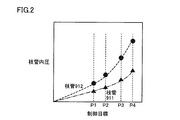
- FIG. 2 is a diagram illustrating an example of changes in the internal pressures of the branch pipes 911 and 912 when the control target of the internal pressure of the main line 910 is changed in the test operation.
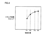
- FIG. 3 is a diagram showing a change in the index of the amount of energy required for driving the compressors 601 to 604 in the supply facility 1000 when the control target for the trunk line 910 is changed in the test operation. 2 and 3 show the results under four types of control targets of pressures P1 to P4.
- FIG. 3 as an example of the energy amount index, power (electric energy) required to compress 1 cubic meter of air is shown.
- the control panel 400 first drives the compressors 601 to 604 so that the internal pressure of the main line 910 is adjusted by the pressure P1 among the above four types of control targets.
- the degree of opening and closing of the valves 731 to 733 is a general state when the facilities 801 to 803 are not operating.
- the control panel 400 After operating for a certain period of time with the control target as the pressure P1, the control panel 400 similarly sets the control target to each of the pressures P2 to P4 and operates the compressors 601 to 604 at regular intervals.
- the controller 100 acquires the measurement results of the pressure sensors 711 to 713 under each control target, and acquires the feature values based on the measurement results.
- the characteristic value is a value representing the characteristic of each measurement result of the pressure sensors 711 to 713 and may be the measurement result itself or an average value of the measurement result (moving average value, etc.).
- the minimum value within a range in which a change in the measurement result is predicted may be used. Details of how to obtain a range in which a change in the measurement result is predicted will be described later.
- the controller 100 acquires the relationship between the internal pressure (feature value) of the branch pipe and the control target as shown in FIG. As understood from FIG. 2, when the control target increases, the internal pressure (characteristic value) of each branch pipe also increases.
- controller 100 obtains an index of the power consumption under each control target by obtaining the power consumption of the compressors 601 to 604 under each control target, and as a result, as shown in FIG. In addition, the relationship between the energy amount index and the control target is acquired.
- the controller 100 acquires the relationship between the internal pressure and the control target for each of the branch pipes 911 to 912, and then the internal pressure (characteristic value) of the branch pipe 911 and the branch pipe 912.
- the lowest branch pressure is specified, and the value of the lowest internal pressure predetermined for the branch pipe thus identified is acquired.
- the value of the internal pressure acquired here is hereinafter also referred to as “management target” in the present specification.
- the controller 100 is based on the state of the branch pipe (and the equipment connected to the branch pipe) that is estimated to be at the lowest risk of lowering the internal pressure in the system.
- the control target can be set.
- the controller 100 determines a new control target corresponding to the management target based on the relationship as shown in FIG. More specifically, a new control target corresponding to a feature value having the same value as the management target (or the smallest feature value equal to or greater than the management target) is determined.
- the controller 100 acquires an energy amount index corresponding to the new control target based on the relationship as shown in FIG.
- the controller 100 acquires a standard control target (first reference value) of the pressure in the main line 910.
- the first reference value is input from the outside, for example.
- the controller 100 acquires an energy amount index corresponding to the first reference value based on the relationship as shown in FIG. 3, and further, an energy amount index corresponding to the first reference value, ( The difference from the energy amount index corresponding to the new control target determined as described above is calculated (so as to satisfy the management target).
- the controller 100 displays on the PC 300 at least one of the difference between the new control target determined as described above, the first reference value, and the energy amount index calculated as described above.
- the administrator of the system in FIG. 1 has changed the pressure in the main line 910 to a specific pressure (for example, 0.65 MPa (mega Pascal))). Then, the administrator inputs 0.65 MPa as the first reference value, and “0.55 MPa”, “0.60 MPa”, “0.65 MPa”, “0.70 MPa” at the time of the test operation of the system.
- the characteristic values of the internal pressure of the branch pipes 911 and 912 were obtained for each of the four types of control targets. At this time, even if the control target is lowered to 0.55 MPa, the characteristic value of the internal pressure of the branch pipe 912 maintains the above management target.
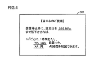
- FIG. 4 is a diagram illustrating an example of a screen displayed as a result of the test operation.
- the screen 301 has a title “Proposal for energy saving” and “If the set pressure is reduced to 0.55 MPa when the apparatus is stopped”, “WAkwh per hour per 1 m 3.
- the message “Can save power and reduce XA yen expenses” is displayed. This message indicates that the system can be maintained safely even if the control target is reduced from 0.65 MPa to 0.55 MPa, that is, the characteristic value of the internal pressure of the branch pipe 912 does not fall below the management target from the result of the test operation. And an approximate value of the power consumption reduced by lowering the control target and an approximate amount of cost to be reduced are presented.
- the controller 100 displays the difference between the energy amount indexes calculated as described above as an approximate value of the power consumption. Moreover, the controller 100 displays the electricity bill corresponding to the difference in the energy amount index as the approximate amount of the cost to be reduced.
- an electricity charge per unit amount of electricity such as 1.5 yen or 1.8 yen per kWh is set in advance. Then, when the controller 100 acquires the difference in the amount of electricity per unit time as the difference in the energy amount index, the controller 100 calculates the product of the difference and the electricity charge per unit amount of electricity as an estimated amount of expense to be reduced. Display as.
- FIG. 5 is a diagram illustrating an example of a prediction range of the measurement result of the internal pressure.
- a method for setting the predicted range of the internal pressure will be described.
- FIG. 5 shows a line LD with a solid line. Further, each of the line L3, the line L4, the line L5, and the line L6 is indicated by different types of broken lines.
- the horizontal axis of the graph of FIG. 5 represents the time when the internal pressure was measured.
- the vertical axis represents the internal pressure.
- a line LD represents the measurement result.
- Line L3, line L4, line L5, and line L6 each represent the lower limit of the prediction range.
- the upper limit is represented by line LD. That is, FIG. 5 shows four types of prediction ranges whose upper limit is a line LD.
- the lower limit of the prediction range is derived, for example, by subtracting the movement deviation ⁇ of the state data in the setting period from the moving average ⁇ in the predetermined setting period of the measurement result.
- Line L3, line L4, line L5, and line L6 are prediction ranges derived using 3 ⁇ , 4 ⁇ , 5 ⁇ , and 6 ⁇ , respectively, and are derived according to the following equations (1) to (4), respectively. .
- the range of the internal pressure between the line LD and each of the line L3, line L4, line L5, or line L6 is the line L3, line L4, line L5, or line L6. It is the prediction range shown by each line.
- the predicted range of the present embodiment indicates a range in which the internal pressure of the branch pipe is predicted to decrease.
- the line L3, the line L4, the line L5, and the line L6 have different coefficients of the movement deviation ⁇ .
- the prediction range expands to a value with a low internal pressure as the coefficient of the movement deviation ⁇ increases negatively. That is, the line L6 corresponding to the coefficient “ ⁇ 6” has the lowest value.
- a prediction range including a larger risk can be derived by increasing the coefficient of the movement deviation ⁇ .
- the lowest value in the prediction range (that is, the value on any one of the lines L3 to L6) is adopted as the characteristic value of the internal pressure.
- the control target of the original pressure is set not based on the value of the internal pressure itself of the branch pipe in the test operation, but based on a value in a range where a change in the internal pressure of the branch pipe is predicted. Therefore, it is possible to propose a reduction in the control target while ensuring with a higher probability that the internal pressure of the branch pipe is maintained above the “management target”.
- FIG. 6 is a diagram schematically illustrating a hardware configuration of the controller 100.
- the controller 100 includes a CPU (Central Processing Unit) 10 that is an arithmetic device for controlling the entire controller 100 and a ROM (Read Only Memory) for storing programs executed by the CPU 10. 11, RAM (Random Access Memory) 12 for functioning as a work area when the program is executed by the CPU 10, reception of measurement results from the pressure sensors 711 to 713, transmission of data to the control panel 400 and the controller 200, etc.
- a communication device 18 realized by a modem or the like for performing communication, a display interface 14 which is an interface when image data is transmitted to the monitor 300A of the PC 300, and an operation unit 15 for receiving an operation input to the controller 100.
- Executed by the CPU 10 It includes a storage unit 16 for storing programs and the like, and a media controller 17 to read or write files from it accesses the removable storage medium M to the controller 100.
- the display interface 14 may be realized by hardware such as a driver board of the monitor 300A, or may be realized as software such as a driver program.
- the operation unit 15 is realized by an input device such as a keyboard or a mouse.
- the CPU 10 executes an appropriate program
- At least a part of the functions of the controller 100 described in the present specification is realized.
- At least a part of the program executed by the CPU 10 may be stored in the storage medium M.
- the storage medium M CD-ROM (Compact Disc-Read Only Memory), DVD-ROM (Digital Versatile Disk-Read Only Memory), USB (Universal Serial Bus) memory, memory card, FD (Flexible Disk), hard disk, Magnetic tape, cassette tape, MO (Magnetic Optical Disc), MD (Mini Disc), IC (Integrated Circuit) card (excluding memory card), optical card, mask ROM, EPROM, EEPROM (Electronically Erasable Programmable Read-Only Memory)
- a medium for storing the program in a nonvolatile manner For example, a medium for storing the program in a nonvolatile manner.
- the program executed by the CPU 10 may be downloaded from the external server device S via the network and installed in the storage device 16.
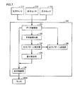
- FIG. 7 is a diagram schematically illustrating a functional configuration of the controller 100.
- the controller 100 includes a data storage unit 101, a predicted value derivation unit 102, an output pattern determination unit 103, a difference derivation unit 104, a display control unit 105, and an output pattern transmission unit 106.
- the data storage unit 101 is realized by the RAM 12 and / or the storage device 16, for example.
- the predicted value deriving unit 102, the output pattern determining unit 103, the difference deriving unit 104, and the display control unit 105 are realized by the CPU 10 executing an appropriate program, for example. On the other hand, it may be realized by independent hardware resources.
- the output pattern transmission unit 106 is realized by the communication device 18 instructed to transmit data by the CPU 10.
- the data accumulation unit 101 receives and accumulates continuous detection outputs (internal pressure measurement results) from the pressure sensors 711 to 713.
- the predicted value deriving unit 102 calculates an index (standard deviation ⁇ described above) based on the measurement result history stored in the data storage unit 101, and calculates the lower limit value of the prediction range using the index. To do.
- the lower limit value of the prediction range is a value calculated by any of the above formulas (1) to (4).
- the controller 100 information specifying in advance which of the equations (1) to (4) is used to calculate the lower limit value, that is, which of 3 ⁇ to 6 ⁇ is used to calculate the lower limit value is registered. ing.
- the controller calculates the lower limit value based on the contents of the registration. The registration of the information is realized, for example, when the user inputs information to the controller 100. Note that the predicted value deriving unit 102 may output an average value of actually measured values without using the standard deviation ⁇ instead of the lower limit value.
- the output pattern determining unit 103 determines the new control target based on the lower limit value or the average value output from the predicted value deriving unit 102 and the relationship as shown in FIG.
- the difference deriving unit 104 based on the relationship as shown in FIG. 3, the energy amount index corresponding to the new control target determined by the output pattern determining unit 103, and a preset control target (the above “first” The difference from the energy amount index corresponding to the “standard value of 1”) is calculated.
- the display control unit 105 displays the result of the test operation as shown in FIG. 4 on the monitor 300A or the like based on the output from each element shown in FIG.
- FIG. 8 is a diagram schematically illustrating a hardware configuration of the controller 200.
- the controller 200 includes a CPU 20 that is an arithmetic device for controlling the controller 200 as a whole, a ROM 21 for storing a program executed by the CPU 20, and operations performed when the CPU 20 executes the program.
- the image data is transmitted to the RAM 22 for functioning as a region, the communication device 28 realized by a modem or the like for communication such as transmission of control signals for the degree of opening / closing to the valves 721, 731 to 733, and an external display device.
- a display interface 24 that is an interface at the time, an operation unit 25 for receiving an operation input to the controller 200, a storage device 26 for storing a program executed by the CPU 20, and the controller 200 can be attached to and detached from the controller 200. Access the storage medium M or there And a media controller 27 to read or write the file.
- Storage media M include CD-ROM, DVD-ROM, USB memory, memory card, FD, hard disk, magnetic tape, cassette tape, MO, MD, IC card (excluding memory card), optical card, mask ROM, EPROM And a medium for storing the program in a nonvolatile manner, such as an EEPROM.
- the program executed by the CPU 20 may be downloaded from an external server device via a network and installed in the storage device 26.
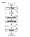
- FIG. 9 is a flowchart of processing executed by the CPU 10 of the controller 100 to present information as shown in FIG. 4 based on the measurement result acquired during the test operation of the system.
- processing contents for presenting information will be described with reference mainly to FIG. 9.
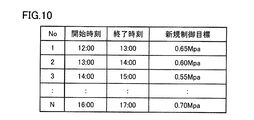
- FIG. 10 is a diagram illustrating an example of a control target pattern in a test operation.
- the start time and end time are set for each control target.
- the control panel 400 adjusts the power of the compressors 601 to 604 so that the pressure of the main line 910 is adjusted to the control target according to each start time and end time.
- the pattern of changing the control target in the test operation as shown in FIG. 10 may be input to the controller 100 and transmitted from the controller 100 to the control panel 400, for example.
- step S20 the CPU 10 calculates a predicted value as described with reference to FIG. 5 based on the measurement result acquired in step S10, and proceeds to step S30.
- the CPU 10 calculates the average value of the measurement result in step S20.
- step S30 the CPU 10 determines a new control target based on the predicted value or average value calculated in step S20 and the relationship as shown in FIG. 3, and advances the process to step S40.
- step S40 the CPU 10 transmits a new control target to the control panel 400, and proceeds to step S50.
- the processing in step S40 can be omitted.
- step S50 the CPU 10 calculates information related to the energy amount (reduced energy amount) that is reduced when the control target is changed from the preset value (first reference value) to the new control target. Then, the process proceeds to step S60.
- an approximate value of the power consumption mentioned in the description of FIG. 4 is calculated.
- step S60 the CPU 10 causes the monitor 300A to display information such as the approximate value of the power consumption as described with reference to FIG. 4, and ends the process.
- the main line 910 is connected to a compressor that supplies compressed air via a pipe 900.
- the branch pipes 911 to 913 are connected to the trunk line 910.
- the branch pipes 911 to 913 are connected to facilities 801 to 803 which are objects to be supplied with compressed air.
- a control panel 400 is provided as a driving device that controls the driving of the compressors 601 to 604 based on an original pressure that is a pressure in the main line 910.
- the relationship between the control target for the original pressure and the amount of energy consumed when the control panel 400 drives the compressors 601 to 604 in accordance with the control target is stored in the recording medium 16 or the like.
- controller 100 obtains the pressure in the branch pipe when the control panel 400 drives the compressors 601 to 604 according to each control target in association with each control target through the communication device 18 during the test operation. To do. Thereby, the controller 100 acquires the relationship (second relationship) between the control target and the branch pressure, which is the pressure in the branch pipe under each control target, as described with reference to FIG.
- controller 100 receives the first reference value for the source pressure and the second reference value for the branch pressure (from the other device such as the PC 300 via the operation unit 15 or the communication device 18). Management target) is received.
- the controller 100 determines a new control target that is a control target of the compressor for maintaining the branch pressure equal to or higher than the second reference value based on the second relationship (step S30). Further, as described as “reduced energy amount”, the controller 100 uses the amount of energy consumed when the drive device drives the compressor according to the first reference value, and when the drive device drives the compressor according to the new control target. A difference from the consumed energy amount is calculated.
- the controller 100 displays the information related to the new control target and the difference.
- the branch pressure associated with the control target in the second relationship is preferably the minimum value of the predicted range of the measurement result of the pressure in the branch pipe under each control target. As a result, a value for more reliably maintaining the pressure in the branch pipe at the second reference value or more is determined as a new control target.
- the coefficient of the movement deviation ⁇ can be selected when calculating the prediction range. More specifically, the coefficient of the movement deviation ⁇ used for determining the new control target can be selected in the range of “ ⁇ 3” to “ ⁇ 6”.
- the system administrator inputs a coefficient to the operation unit 15, for example.
- the predicted value derivation unit 102 calculates a predicted range using the input coefficient.
- the controller 100 controls the control target (new control) for maintaining the internal pressure of the branch pipe at or above the second target value based on the measurement result acquired during the test operation of the system. Target). Then, as described with reference to FIG. 4 and the like, the controller 100 displays information such as the amount of energy saved when assuming that the control target is updated to the new control target. As a result, the controller 100 can propose to the system administrator a reduction in the control target while ensuring the safety of maintaining the internal pressure of the branch pipe above the second target value.
- the controller 100 sets the new control target even during the normal operation period of the system, that is, the period during which at least one of the facilities 801 to 803 is operating (the period during which power is supplied). You may decide.
- the controller 100 can transmit the determined new control target to the control panel 400.
- the controller 100 determines a new control target, for example, at regular intervals, and transmits the new control target to the control panel 400.
- the control panel 400 sets a new control target acquired from the controller 100 as a control target, and controls the driving of the compressors 601 to 604.
- a new control target is determined based on the branch pipes 911 to 913 having the lowest internal pressure.
- the connected equipment equipment 801 to 803
- the internal pressure is expected to decrease.
- the operation of the connected equipment among the plurality of branch pipes 911 to 913 stops, it is considered that the internal pressure does not decrease due to the operation of the equipment. That is, in the normal operation period, the internal pressure of each branch pipe may vary depending on the operation status of the connected equipment.
- the control panel 400 By receiving a new control target in real time from the controller 100 during the normal operation period, the control panel 400 suppresses the target for increasing the pressure of the main line 910 to the minimum necessary according to the operation status of each facility in the system. Can do. Therefore, the control panel 400 controls the driving of the compressors 601 to 604 based on the new control target provided in real time from the controller 100, thereby maintaining the branch pipe pressure at the first reference value or higher in the system. As a result, waste of power from the compressors 601 to 604 can be more reliably omitted.
- the new control target is calculated based on the minimum value of the prediction range instead of the branch pressure measurement result, so that the internal pressure of the branch pipe is more reliably held at the first reference value or more. obtain.
Landscapes
- Engineering & Computer Science (AREA)
- Computer Hardware Design (AREA)
- Mechanical Engineering (AREA)
- General Engineering & Computer Science (AREA)
- Control Of Positive-Displacement Pumps (AREA)
Abstract
コントローラ(100)は、システムの試験稼働の際に取得された計測結果に基づいて、枝管の内圧を第2の目標値以上に維持するための制御目標(新規制御目標)を決定する。そして、コントローラ(100)は、制御目標が新規制御目標へと更新されたことを想定した、節約されるエネルギ量等の情報を表示する。
Description
本開示は、システムの制御に関し、特に、種々の装置に圧縮空気を供給するシステムを制御するための制御装置およびその制御方法、当該システムにおいて利用されるコンピュータが実行するプログラム、ならびに、このような制御装置を備える制御システムに関する。
従来、工場等のシステムにおける消費電力の低減に関し、種々の技術が開示されている。たとえば、特許文献1(特開2001-034323号公報)には、自己の消費電力を測定して外部へ送信する工作機械が開示されている。特許文献2(特開2007-148726号公報)には、工場において、工程ごとに、用力負荷の推移やエネルギー消費量の推移を含むエネルギー消費を分析する装置が開示されている。
また、上記のようなシステムでは、圧縮空気送出用コンプレッサから、配管を介して、各装置に圧縮空気を供給するものがある。このようなシステムについて、コンプレッサの駆動によるエネルギ消費を抑えるための種々の技術が開示されている。たとえば、特許文献3(特開2004-176683号公報)、特許文献4(特開2007-291870号公報)、特許文献5(特開2011-226586号公報)、および、特許文献6(特開2012-031789号公報)には、コンプレッサの電力消費を抑えるための技術が開示されている。
特許文献3~特許文献6に開示された技術では、コンプレッサに近い配管において計測された空気圧に基づいて、コンプレッサの駆動が制御される。なお、一般的なシステムでは、配管は、コンプレッサから直接的に圧縮空気を導入される主管と、当該主管から延びる枝管とを含む。そして、圧縮空気を供給される装置は、枝管に接続される。そして、従来の技術では、主管の空気圧を用いて、コンプレッサの駆動が制御されていた。
このような従来の技術によれば、枝管や当該枝管に接続された装置において十分な空気圧が保たれるように、主管の空気圧は、必要な空気圧に対して多少の余裕を持つように制御される必要がある。また、上記のような装置のオペレータや管理者は、当該装置を利用していないときであっても、当該装置に供給される空気圧が低減された場合に、当該装置を含む作業環境に何らかの不具合が生じることを懸念する場合が多い。
以上のように、上記のような圧縮空気を供給するシステムでは、コンプレッサの駆動のための電力消費を抑えることを困難にする事情が依然として残されている。
本開示は、かかる実情に鑑み考え出されたものであり、その目的は、コンプレッサから装置に圧縮空気を供給するシステムにおける当該コンプレッサの駆動電力の低減に寄与することである。
ある局面に従うと、圧縮空気を供給するコンプレッサに接続された幹線と、幹線に接続された枝管と、枝管に接続され圧縮空気を供給される対象物と、幹線内の圧力である元圧に基づいてコンプレッサの駆動を制御する駆動装置とを備えるシステムを制御するためのシステム制御装置が提供される。システム制御装置は、元圧についての制御目標と、当該制御目標に従って駆動装置がコンプレッサを駆動したときの消費エネルギ量との関係である、第1の関係を記憶するための記憶部と、制御目標と、当該制御目標に従って駆動装置がコンプレッサを駆動したときの枝管内の圧力である枝圧との関係である、第2の関係を取得するための取得部と、元圧についての第1の基準値および枝圧についての第2の基準値の入力を受け付けるための入力部と、第2の関係に基づいて、第2の基準値以上の枝圧を維持するためのコンプレッサの制御目標である新規制御目標を決定するための決定部と、第1の基準値に従って駆動装置がコンプレッサを駆動したときの消費エネルギ量と、新規制御目標に従って駆動装置がコンプレッサを駆動したときの消費エネルギ量との差を算出するための差分算出部と、新規制御目標および差に関連する情報を表示するための表示部とを備える。
好ましくは、システム制御装置は、駆動装置が制御目標でコンプレッサを駆動している期間、枝管内の圧力の連続的な計測結果を蓄積するための蓄積部と、枝圧の計測結果の安定性の指標を、時系列の複数の計測結果に基づいて連続的に導出し、さらに、計測結果と指標とに基づいて計測結果が変化することが予測される範囲である予測範囲を導出するための導出部とをさらに備える。第2の関係は、制御目標と、当該制御目標に対応する枝管内の圧力の計測結果に対する予測範囲における最小値との関係である。
好ましくは、入力部は、計測結果が到達する確率の入力をさらに受け付ける。導出部は、入力された確率に対応する指標および予測範囲を導出する。
好ましくは、幹線には、2以上の枝管が接続される。決定部は、2以上の枝管のうち、制御目標に従って駆動装置がコンプレッサを駆動したときの枝圧が最も低い枝管の枝圧を第2の基準値以上で維持するための新規制御目標を決定する。
他の局面に従うと、圧縮空気を供給するコンプレッサに接続された幹線と、幹線に接続された枝管と、枝管に接続され圧縮空気を供給される対象物と、幹線内の圧力である元圧に基づいてコンプレッサの駆動を制御する駆動装置とを備えるシステムを制御するための制御装置の制御方法が提供される。制御装置は、元圧についての制御目標と、当該制御目標に従って駆動装置がコンプレッサを駆動したときの消費エネルギ量との関係である、第1の関係を記憶するための記憶装置を含む。制御方法は、当該制御装置のコンピュータが、制御目標と、当該制御目標に従って駆動装置がコンプレッサを駆動したときの枝管内の圧力である枝圧との関係である、第2の関係を取得するステップと、元圧についての第1の基準値および枝圧についての第2の基準値の入力を受け付けるステップと、第2の関係に基づいて、第2の基準値以上の枝圧を維持するためのコンプレッサの制御目標である新規制御目標を決定するステップと、第1の基準値に従って駆動装置がコンプレッサを駆動したときの消費エネルギ量と、新規制御目標に従って駆動装置がコンプレッサを駆動したときの消費エネルギ量との差を算出するステップと、新規制御目標および差に関連する情報を表示するステップとを含む。
さらに他の局面に従うと、圧縮空気を供給するコンプレッサに接続された幹線と、幹線に接続された枝管と、枝管に接続され圧縮空気を供給される対象物と、幹線内の圧力である元圧に基づいてコンプレッサの駆動を制御する駆動装置とを備えるシステムを制御するためのコンピュータが実行可能なプログラムが提供される。制御装置は、元圧についての制御目標と、当該制御目標に従って駆動装置がコンプレッサを駆動したときの消費エネルギ量との関係である、第1の関係を記憶するための記憶装置を含む。プログラムは、コンピュータに、制御目標と、当該制御目標に従って駆動装置がコンプレッサを駆動したときの枝管内の圧力である枝圧との関係である、第2の関係を取得するステップと、元圧についての第1の基準値および枝圧についての第2の基準値の入力を受け付けるステップと、第2の関係に基づいて、第2の基準値以上の枝圧を維持するためのコンプレッサの制御目標である新規制御目標を決定するステップと、第1の基準値に従って駆動装置がコンプレッサを駆動したときの消費エネルギ量と、新規制御目標に従って駆動装置がコンプレッサを駆動したときの消費エネルギ量との差を算出するステップと、新規制御目標および差に関連する情報を表示するステップとを実行させる。
さらに他の局面に従うと、圧縮空気を供給するコンプレッサに接続された幹線と、幹線に接続された枝管と、枝管に接続され圧縮空気を供給される対象物と、幹線内の圧力である元圧に基づいてコンプレッサの駆動を制御する駆動装置とを備えるシステムを制御するためプログラムをコンピュータによって読取可能に非一時的に記憶する記憶媒体が提供される。コンピュータは、元圧についての制御目標と、当該制御目標に従って駆動装置がコンプレッサを駆動したときの消費エネルギ量との関係である、第1の関係を記憶するための記憶装置を含む。プログラムは、コンピュータに、制御目標と、当該制御目標に従って駆動装置がコンプレッサを駆動したときの枝管内の圧力である枝圧との関係である、第2の関係を取得するステップと、元圧についての第1の基準値および枝圧についての第2の基準値の入力を受け付けるステップと、第2の関係に基づいて、第2の基準値以上の枝圧を維持するためのコンプレッサの制御目標である新規制御目標を決定するステップと、第1の基準値に従って駆動装置がコンプレッサを駆動したときの消費エネルギ量と、新規制御目標に従って駆動装置がコンプレッサを駆動したときの消費エネルギ量との差を算出するステップと、新規制御目標および差に関連する情報を表示するステップとを実行させる。
別の局面に従うと、上記したようなシステム制御装置と、上記したような駆動装置とを備える制御システムが提供される。制御システムでは、システム制御装置は、決定部が決定した新規制御目標を駆動装置に送信するための送信部をさらに含み、駆動装置は、コンプレッサの駆動制御についての目標値を、新規制御目標に更新する。
ある局面に従うと、システム制御装置は、基準値以上の枝圧を維持するためのコンプレッサの制御目標である新規制御目標を決定し、入力された基準値に従って駆動装置がコンプレッサを駆動したときの消費エネルギ量と、新規制御目標に従って駆動装置がコンプレッサを駆動したときの消費エネルギ量との差を算出する。そして、システム制御装置は、新規制御目標と、上記差に関連する情報とを、表示する。
これにより、システムの管理者に、基準値以上の枝圧が維持される制御目標の一例として新規制御目標が提供され、さらに、制御目標が新規制御目標に変更された場合の消費エネルギ量の差に関連する情報が提供される。
以下、システム制御装置の実施の形態について、図面を参照しつつ説明する。なお、同一の構成要素には各図において同一の符号を付し、詳細な説明は繰返さない。
[システムの概要]
図1は、システム制御装置の制御対象となるシステムの構成の概要を示す図である。図1を参照して、当該システムの構成の概要を説明する。
図1は、システム制御装置の制御対象となるシステムの構成の概要を示す図である。図1を参照して、当該システムの構成の概要を説明する。
図1のシステムは、供給設備1000と、消費設備2000とを含む。消費設備2000は、圧縮空気の供給を受けて、製品の製造や研磨等の処理を行う設備801~803を含む。供給設備1000は、設備801~803に供給される圧縮空気を生成するコンプレッサ601~604を含む。
供給設備1000は、コンプレッサ601~604において生成された圧縮空気は、配管900を介して、タンク500で貯蔵される。タンク500に貯蔵された圧縮空気は、幹線910を介して、消費設備2000へと送られる。幹線910には、当該幹線910内の圧力を計測するためのセンサ701が設けられている。供給設備1000において、制御盤400は、センサ701の計測結果に基づいて、幹線910内の圧力を当該幹線910の制御目標で維持するために、コンプレッサ601~604を駆動する。制御盤400は、たとえば、センサ701の計測結果を利用し、PID(Proportional Integral Differential)制御により、コンプレッサ601~604を駆動する。
制御盤400は、センサ701の計測結果に基づいて、コンプレッサ601~604の中のコンプレッサの駆動台数を決定する場合もある。より具体的には、制御盤400は、幹線910内の圧力が低くなると、コンプレッサ601~604のうち駆動させるコンプレッサの台数を増加させ、幹線910内の圧力が高くなると、駆動させるコンプレッサの台数を低減させる。
消費設備2000には、幹線910から各設備801~803へと圧縮空気を送るための枝管911~913が設けられている。幹線910は、たとえば施設のダクト内に設けられている。枝管911~913は、当該ダクトから施設内の設備へと引き出された配管として構成される。一般的に、枝管911~913の径(10mm程度)は、幹線910の径(50mm程度)よりも小さく構成される。
枝管911~913のそれぞれには、各枝管内の圧力を計測するための圧力センサ711~713、および、設備801~803のそれぞれへの圧縮空気の供給量を調整するためのバルブ731,732,733が設けられている。幹線910の、バルブ731,732,733よりも上流側(供給設備1000に近い側)に、供給設備1000から消費設備2000への圧縮空気の供給量を調整するためのバルブ721が設けられている。
消費設備2000には、さらに、コントローラ100とコントローラ200とが設けられている。コントローラ100は、圧力センサ711~713の計測結果等に基づいて、幹線910の圧力についての制御目標の提示等を行う。コントローラ200は、コントローラ100を介して圧力センサ711~713のそれぞれの計測結果を受信し、当該計測結果に基づいて、バルブ721およびバルブ731,732,733のそれぞれの開閉動作を制御する。
コントローラ100は、幹線910の圧力についての種々の制御目標と、各制御目標に要するエネルギ量との関係を格納している。より具体的には、図1のシステムでは、たとえば試験稼働の際に、幹線910内の圧力の制御目標をいくつか選択し、各制御目標に従って、コンプレッサ601~604が駆動される。コントローラ100には、当該試験稼働における各制御目標での駆動の際のコンプレッサ601~604において消費されるエネルギ量(または当該エネルギ量の指標となる値)が格納される。
本実施の形態において、試験稼働が実行される期間は、システムが新規に利用を開始される時に限定されない。稼働中のシステムについて、生産が予定されていない期間等、稼働を停止することができる期間中に実行される場合もあり得る。
また、コントローラ100には、当該試験稼働における各制御目標での駆動の際の、圧力センサ711~713の計測結果が格納される。
そして、コントローラ100は、圧力センサ711~713の計測結果に基づいて、枝管911~913のそれぞれに対して求められる最低限の圧力を実現するための制御目標(新規制御目標)を決定する。また、コントローラ100は、制御目標の基準値の入力を受け付ける。そして、コントローラ100は、上記のように決定した新規制御目標と、入力を受け付けた制御目標の基準値のそれぞれについて、消費エネルギ量またはその指標を取得する。そして、決定した新規制御目標、予め入力されていた制御目標の基準値、および、これらの差、ならびに、これらの消費エネルギ量の差またはこれらの指標の差を、表示する。
コントローラ100は、表示装置を備えていてもよいし、備えていなくともよい。コントローラ100は、上記表示を、当該コントローラ100に備えられた表示装置で行ってもよいし、他の機器において行ってもよい。本実施の形態では、コントローラ100は、パーソナルコンピュータ(以下、「PC」と略す)300と通信可能である。そして、コントローラ100は、PC300のディスプレイ(後述するモニタ300A)において上記表示を行ってもよい。
コントローラ100は、決定した新規制御目標を制御盤400へ送信することが好ましい。この場合、制御盤400は、コントローラ100が決定した新規制御目標で、コンプレッサ601~604の駆動を制御する。
また、コントローラ100は、枝管911~913の中の少なくとも一つについて、内圧の計測結果を、コントローラ200へ送信することが好ましい。コントローラ200は、受信した枝管の内圧に基づいて、当該内圧について予め設定された最低限の圧力以上となるように、バルブ721およびバルブ731の開閉度合いを調整する。
[新規制御目標の決定]
図2および図3は、コントローラ100が上記したように新規制御目標を決定するために利用するデータの一例を模式的に示す図である。図2は、試験稼働において、幹線910の内圧の制御目標を変化させた際の、枝管911,912のそれぞれの内圧の変化の一例を示す図である。図3は、試験稼働において幹線910についての制御目標を変化させた際の、供給設備1000におけるコンプレッサ601~604の駆動に要するエネルギ量の指標の変化を示す図である。図2および図3では、圧力P1~P4の4種類の制御目標下での結果が示されている。図3では、エネルギ量の指標の一例として、1立方メートルの空気を圧縮するのに要する動力(電力量)が示されている。以下の説明では、枝管911と枝管912に設備が接続されている例について、説明する。
図2および図3は、コントローラ100が上記したように新規制御目標を決定するために利用するデータの一例を模式的に示す図である。図2は、試験稼働において、幹線910の内圧の制御目標を変化させた際の、枝管911,912のそれぞれの内圧の変化の一例を示す図である。図3は、試験稼働において幹線910についての制御目標を変化させた際の、供給設備1000におけるコンプレッサ601~604の駆動に要するエネルギ量の指標の変化を示す図である。図2および図3では、圧力P1~P4の4種類の制御目標下での結果が示されている。図3では、エネルギ量の指標の一例として、1立方メートルの空気を圧縮するのに要する動力(電力量)が示されている。以下の説明では、枝管911と枝管912に設備が接続されている例について、説明する。
試験稼働の際、図1のシステムにおいて、制御盤400は、まず、上記4種類の制御目標のうち圧力P1で幹線910の内圧が調整されるように、コンプレッサ601~604を駆動する。このとき、バルブ731~733の開閉の度合いは、設備801~803が稼働を停止している際の一般的な状態とされている。制御目標を圧力P1として一定の時間稼働を行った後、制御盤400は、同様に、制御目標を圧力P2~P4のそれぞれに設定して、一定の時間ごと、コンプレッサ601~604を稼働する。
コントローラ100は、各制御目標下で、圧力センサ711~713のそれぞれの計測結果を取得し、当該計測結果に基づいてその特徴値を取得する。特徴値とは、圧力センサ711~713のそれぞれの計測結果の特徴を表す値であって、計測結果そのものの場合もあれば、計測結果の平均値(移動平均値等)であってもよいし、当該計測結果の変化が予測される範囲での最低値であってもよい。計測結果の変化が予測される範囲の求め方の詳細について、後述する。
上記のように特徴値を取得することにより、コントローラ100は、図2に示されたような、枝管の内圧(の特徴値)と制御目標との関係を取得する。図2から理解されるように、制御目標が上昇すれば、各枝管の内圧(の特徴値)も上昇する。
また、コントローラ100は、各制御目標下でのコンプレッサ601~604の消費電力量を取得することにより各制御目標下での消費電力量の指標を取得し、これにより、図3に示されたような、エネルギ量の指標と制御目標との関係を取得する。
コントローラ100は、図2に示されたように、枝管911~912のそれぞれについての内圧と制御目標との関係を取得した後、枝管911と枝管912のうち、内圧(の特徴値)が最も低い枝管を特定し、さらに、このように特定した枝管について予め定められた最低レベルの内圧の値を取得する。ここで取得された内圧の値を、本明細書では、以降、「管理目標」とも呼ぶ。内圧が最も低い枝管が特定されることにより、コントローラ100は、システムにおいて最も内圧低下の危険性があると推定される枝管(および、そのうな枝管に接続された設備)の状態に基づいて、制御目標を設定することができる。
コントローラ100は、管理目標を取得すると、図2に示されたような関係に基づいて、当該管理目標に対応する新規制御目標を決定する。より具体的には、当該管理目標と同じ値の特徴値(または、当該管理目標以上の一番小さい特徴値)に対応する新規制御目標を決定する。
次に、コントローラ100は、図3に示されたような関係に基づいて、新規制御目標に対応するエネルギ量指標を取得する。
一方、コントローラ100は、幹線910内の圧力の標準的な制御目標(第1の基準値)を取得する。第1の基準値は、たとえば、外部から入力される。そして、コントローラ100は、図3に示されたような関係に基づいて、第1の基準値に対応するエネルギ量指標を取得し、さらに、第1の基準値に対応するエネルギ量指標と、(管理目標を満たすように)上記のように決定した新規制御目標に対応するエネルギ量指標との差を算出する。そして、コントローラ100は、上記のように決定した新規制御目標、第1の基準値、上記のように算出したエネルギ量指標の差の少なくとも一つを、PC300に表示する。
上記のようなコントローラ100の処理内容の一例をより具体的に説明すると、たとえば、図1のシステムの管理者は、これまで、幹線910内の圧力を特定の圧力(たとえば、0.65MPa(メガパスカル))で設定していた。そして、管理者は、上記第1の基準値として、0.65MPaを入力し、また、システムの試験稼働の際、「0.55MPa」「0.60MPa」「0.65MPa」「0.70MPa」の4種類の制御目標のそれぞれについて、枝管911,912の内圧の特徴値を取得した。このとき、制御目標を0.55MPaまで低下させても、枝管912の内圧の特徴値は、管理目標を以上を維持していたとする。この場合、当該試験稼働の結果として、コントローラ100は、制御目標0.65MPaに対応するエネルギ量指標と、制御目標0.55MPaに対応するエネルギ量指標の差を算出する。そして、コントローラ100は、当該差を、PC300に表示させる。図4は、試験稼働の結果として表示される画面の一例を示す図である。
図4を参照して、画面301には、「省エネのご提案」というタイトルとともに、「装置停止時に、設定圧を0.55MPaまで低下させれば、」「1m3ごとに、1時間あたり、WAkwh節電でき、XA円経費を削減できます。」というメッセージが表示されている。このメッセージは、試験稼働の結果から、制御目標を0.65MPaから0.55MPaまで低下させても、システムを安全に維持できる、つまり、枝管912の内圧の特徴値が管理目標を下回らないことを伝えるとともに、制御目標を低下させることによる削減される消費電力量の概算値、および、削減される経費の概算量を提示する。
コントローラ100は、消費電力量の概算値として、上記のように算出したエネルギ量指標の差を表示する。また、コントローラ100は、削減される経費の概算量として、エネルギ量指標の差に対応する電気料金を表示する。コントローラ100には、たとえば1kWhあたり1.5円,1.8円等、予め単位電気量あたりの電気料金が設定されている。そして、コントローラ100は、上記したエネルギ量指標の差として、単位時間あたりの電気量の差を取得した場合、当該差と単位電気量あたりの電気料金との積を、削減される経費の概算量として表示する。
[特徴値の算出]
上記したように、試験稼働における制御目標と枝管911,912の内圧とが図2に示されるように関連付けるとき、内圧として、内圧の計測結果の変化が予測される範囲(以下、単に「内圧の予測範囲」ともいう)の最低値が採用される場合がある。図5は、内圧の計測結果の予測範囲の一例を示す図である。以下、図5を参照して、内圧の予測範囲の設定方法を説明する。
上記したように、試験稼働における制御目標と枝管911,912の内圧とが図2に示されるように関連付けるとき、内圧として、内圧の計測結果の変化が予測される範囲(以下、単に「内圧の予測範囲」ともいう)の最低値が採用される場合がある。図5は、内圧の計測結果の予測範囲の一例を示す図である。以下、図5を参照して、内圧の予測範囲の設定方法を説明する。
図5には、実線で線LDが記載されている。また、線L3、線L4、線L5、および線L6のそれぞれが互いに種類の異なる破線で記載されている。図5のグラフの横軸は、内圧が計測された時刻を表す。縦軸は、内圧を表す。線LDは、計測結果を表す。線L3、線L4、線L5、および線L6は、それぞれ、予測範囲の下限を表す。上限は、線LDによって表される。つまり、図5には、上限を線LDとする4種類の予測範囲が示されている。
予測範囲の下限は、たとえば、計測結果の予め定められた設定期間における移動平均μから、当該設定期間における状態データの移動偏差σを差し引くことによって導出される。線L3、線L4、線L5、および線L6は、それぞれ、3σ、4σ、5σ、6σを用いて導出された予測範囲であり、それぞれ次の式(1)~式(4)に従って導出される。
線L3=μ-3σ …(1)
線L4=μ-4σ …(2)
線L5=μ-5σ …(3)
線L6=μ-6σ …(4)
図5に示された例では、線LDと、線L3、線L4、線L5、または線L6のそれぞれの線との間の内圧の範囲が、線L3、線L4、線L5、または線L6のそれぞれの線で示される予測範囲である。本実施の形態の予測範囲は、枝管の内圧が低下することが予測される範囲を示す。
線L4=μ-4σ …(2)
線L5=μ-5σ …(3)
線L6=μ-6σ …(4)
図5に示された例では、線LDと、線L3、線L4、線L5、または線L6のそれぞれの線との間の内圧の範囲が、線L3、線L4、線L5、または線L6のそれぞれの線で示される予測範囲である。本実施の形態の予測範囲は、枝管の内圧が低下することが予測される範囲を示す。
線L3、線L4、線L5、線L6は、互いに、移動偏差σの係数が異なる。線L3、線L4、線L5、および線L6のうち、図5に示されたすべての時間範囲において、移動偏差σの係数が負に大きくなるほど、予測範囲が内圧の低い値まで広がっている。つまり、係数「-6」に対応する線L6は、最も低い値を取っている。本実施の形態では、移動偏差σの係数を大きくすることにより、より大きなリスクを含む予測範囲を導出することができる。
本実施の形態では、図2に示されたような関係では、内圧の特徴値として、予測範囲における最低の値(つまり、線L3~線L6のいずれかの線上の値)が採用される場合があり得る。この場合、元圧の制御目標は、試験稼働における枝管の内圧そのものの値ではなく、当該枝管の内圧の変化が予測される範囲の値に基づいて、設定される。したがって、枝管の内圧が上記「管理目標」以上を保つことをより高い確率で保証した上で、制御目標の低減を提案することができる。
[コントローラ100のハードウェア構成]
図6は、コントローラ100のハードウェア構成を模式的に示す図である。
図6は、コントローラ100のハードウェア構成を模式的に示す図である。
図6を参照して、コントローラ100は、コントローラ100全体を制御するための演算装置であるCPU(Central Processing Unit)10と、CPU10で実行されるプログラムなどを記憶するためのROM(Read Only Memory)11と、CPU10でプログラムを実行する際の作業領域として機能するためのRAM(Random Access Memory)12と、圧力センサ711~713からの計測結果の受信や制御盤400およびコントローラ200対するデータの送信などの通信を行なうモデム等により実現される通信装置18と、PC300のモニタ300Aに画像データが送信される際のインターフェースである表示用インターフェース14と、コントローラ100に対する操作入力を受付けるための操作部15と、CPU10によって実行されるプログラム等を格納するための記憶装置16と、コントローラ100に対して着脱可能な記憶媒体Mにアクセスしてそこからファイルを読み出したり書き込んだりするためのメディアコントローラ17とを含む。
表示用インターフェース14は、モニタ300Aのドライバ用の基板などのハードウェアによって実現されてもよいし、ドライバプログラムなどのソフトウェアとして実現されても良い。操作部15は、たとえばキーボードやマウスなどの入力装置によって実現される。
本実施の形態では、たとえば、CPU10が適切なプログラムを実行することにより、本明細書に記載されたコントローラ100の機能の少なくとも一部が実現される。CPU10が実行するプログラムの少なくとも一部は、上記記憶媒体Mに記憶されていても良い。記憶媒体Mとしては、CD-ROM(Compact Disc - Read Only Memory)、DVD-ROM(Digital Versatile Disk - Read Only Memory)、USB(Universal Serial Bus)メモリ、メモリカード、FD(Flexible Disk)、ハードディスク、磁気テープ、カセットテープ、MO(Magnetic Optical Disc)、MD(Mini Disc)、IC(Integrated Circuit)カード(メモリカードを除く)、光カード、マスクROM、EPROM、EEPROM(Electronically Erasable Programmable Read-Only Memory)などの、不揮発的にプログラムを格納する媒体が挙げられる。
また、CPU10が実行するプログラムは、ネットワークを介して、外部のサーバ装置Sからダウンロードされ、記憶装置16にインストールされる場合も有り得る。
[コントローラ100の機能構成]
図7は、コントローラ100の機能構成を模式的に示す図である。
図7は、コントローラ100の機能構成を模式的に示す図である。
図7を参照して、コントローラ100は、データ蓄積部101と、予測値導出部102と、出力パターン決定部103と、差分導出部104と、表示制御部105と、出力パターン送信部106とを含む。データ蓄積部101は、たとえば、RAM12および/または記憶装置16によって実現される。予測値導出部102と、出力パターン決定部103と、差分導出部104と、表示制御部105とは、たとえばCPU10が適切なプログラムを実行することによって実現されるが、専用の回路等、CPU10に対して独立したハードウェア資源によって実現される場合もあり得る。出力パターン送信部106は、CPU10によってデータの送信を指示される通信装置18によって実現される。
データ蓄積部101は、圧力センサ711~713からの連続的な検出出力(内圧の計測結果)を、受信し、蓄積する。
予測値導出部102は、データ蓄積部101に蓄積された計測結果の履歴に基づいて、指標(上記した標準偏差σ)を算出し、そして、当該指標を用いて、予測範囲の下限値を算出する。予測範囲の下限値とは、上記の式(1)~(4)のいずれかによって算出される値である。コントローラ100では、予め、式(1)~(4)のいずれに基づいて下限値を算出するか、つまり、下限値の算出に3σ~6σのいずれを利用するかを、指定する情報が登録されている。コントローラは、当該登録の内容に基づいて、下限値を算出する。当該情報の登録は、たとえば、ユーザがコントローラ100に対して情報を入力することにより、実現される。なお、予測値導出部102は、上記下限値の代わりに、標準偏差σを利用することなく、実測値の平均値を出力する場合もあり得る。
出力パターン決定部103は、上記した予測値導出部102から出力される下限値または平均値と、図2に示されたような関係とに基づいて、上記の新規制御目標を決定する。
差分導出部104は、図3に示されたような関係に基づいて、出力パターン決定部103が決定した新規制御目標に対応するエネルギ量指標と、予め設定されている制御目標(上記した「第1の基準値」)に対応するエネルギ量指標との差を算出する。
表示制御部105は、図7に示された各要素からの出力に基づいて、図4に示されたような、試験稼働の結果を、モニタ300A等に表示する。
[コントローラ200のハードウェア構成]
図8は、コントローラ200のハードウェア構成を模式的に示す図である。
図8は、コントローラ200のハードウェア構成を模式的に示す図である。
図8を参照して、コントローラ200は、コントローラ200全体を制御するための演算装置であるCPU20と、CPU20で実行されるプログラムなどを記憶するためのROM21と、CPU20でプログラムを実行する際の作業領域として機能するためのRAM22と、バルブ721,731~733に対する開閉度合いの制御信号の送信などの通信を行なうモデム等により実現される通信装置28と、外部の表示装置に画像データが送信される際のインターフェースである表示用インターフェース24と、コントローラ200に対する操作入力を受付けるための操作部25と、CPU20によって実行されるプログラム等を格納するための記憶装置26と、コントローラ200に対して着脱可能な記憶媒体Mにアクセスしてそこからファイルを読み出したり書き込んだりするためのメディアコントローラ27とを含む。
本実施の形態では、たとえば、CPU20が適切なプログラムを実行することにより、本明細書に記載されたコントローラ200の機能の少なくとも一部が実現される。CPU20が実行するプログラムの少なくとも一部は、上記記憶媒体Mに記憶されていても良い。記憶媒体Mとしては、CD-ROM、DVD-ROM、USBメモリ、メモリカード、FD、ハードディスク、磁気テープ、カセットテープ、MO、MD、ICカード(メモリカードを除く)、光カード、マスクROM、EPROM、EEPROMなどの、不揮発的にプログラムを格納する媒体が挙げられる。また、CPU20が実行するプログラムは、ネットワークを介して、外部のサーバ装置からダウンロードされ、記憶装置26にインストールされる場合も有り得る。
[試験稼働における情報提示のためのフロー]
図9は、システムの試験稼働の際に取得された計測結果に基づいて、図4に示されたような情報の提示のために、コントローラ100のCPU10が実行する処理のフローチャートである。以下、図9を主に参照して、情報の提示のための処理内容を説明する。
図9は、システムの試験稼働の際に取得された計測結果に基づいて、図4に示されたような情報の提示のために、コントローラ100のCPU10が実行する処理のフローチャートである。以下、図9を主に参照して、情報の提示のための処理内容を説明する。
試験稼働では、上記したように、種々の制御目標下でコンプレッサ601~604の動作が制御される。図10は、試験稼働における、制御目標のパターンの一例を示す図である。
図10のパターンでは、制御目標ごとに開始時刻と終了時刻が設定されている。制御盤400は、各開始時刻と終了時刻に従って、幹線910の圧力が制御目標に調整されるように、コンプレッサ601~604の動力を調整する。図10に示されたような試験稼働における制御目標の変更のパターンは、たとえばコントローラ100に入力され、コントローラ100から制御盤400へ送信される場合があり得る。
図9に戻って、ステップS20で、CPU10は、ステップS10で取得した計測結果に基づき、図5を参照して説明したように予測値を算出して、ステップS30へ処理を進める。なお、新規制御目標の決定に、予測値の代わりに計測結果の平均値が利用される場合には、CPU10は、ステップS20で、計測結果の平均値を算出する。
ステップS30では、CPU10は、ステップS20で算出した予測値または平均値と図3に示されたような関係とに基づいて新規制御目標を決定して、ステップS40へ処理を進める。
ステップS40では、CPU10は、制御盤400に、新規制御目標を送信して、ステップS50へ処理を進める。なお、システムにおいて、制御目標の変更がシステム管理者による手動で行われる場合には、ステップS40における処理は省略され得る。
ステップS50では、CPU10は、制御目標が予め設定されていた値(第1の基準値)から新規制御目標へと変更された場合に削減されるエネルギ量(削減エネルギ量)に関連する情報を算出して、ステップS60へ処理を進める。ここでは、たとえば図4の説明において言及された消費電力量の概算値などが算出される。
ステップS60では、CPU10は、図4を参照して説明したような、消費電力量の概算値などの情報をモニタ300Aに表示させて、処理を終了する。
[実施の形態のまとめ]
以上説明した図1に示されたシステムでは、幹線910は、配管900を介して、圧縮空気を供給するコンプレッサに接続される。枝管911~913は、幹線910に接続される。枝管911~913には、圧縮空気を供給される対象物である設備801~803が接続される。また、幹線910内の圧力である元圧に基づいてコンプレッサ601~604の駆動を制御する駆動装置として、制御盤400が設けられている。
以上説明した図1に示されたシステムでは、幹線910は、配管900を介して、圧縮空気を供給するコンプレッサに接続される。枝管911~913は、幹線910に接続される。枝管911~913には、圧縮空気を供給される対象物である設備801~803が接続される。また、幹線910内の圧力である元圧に基づいてコンプレッサ601~604の駆動を制御する駆動装置として、制御盤400が設けられている。
コントローラ100では、図3を参照して説明したように、元圧についての制御目標と、当該制御目標に従って制御盤400がコンプレッサ601~604を駆動したときの消費エネルギ量との関係(第1の関係)が、記録媒体16等に格納されている。
また、コントローラ100は、試験稼働の際に、通信装置18を介して、各制御目標に従って制御盤400がコンプレッサ601~604を駆動したときの枝管内の圧力を、各制御目標に関連付けて、取得する。これにより、コントローラ100は、図2を参照して説明したような、制御目標と、各制御目標下での枝管内の圧力である枝圧との関係(第2の関係)を取得する。
また、コントローラ100は、操作部15を介して、または、通信装置18を介してPC300等の他の装置から、元圧についての第1の基準値と、枝圧についての第2の基準値(管理目標)の入力を受け付ける。
そして、コントローラ100は、上記第2の関係に基づいて、第2の基準値以上の枝圧を維持するためのコンプレッサの制御目標である新規制御目標を決定する(ステップS30)。また、コントローラ100は、「削減エネルギ量」として説明したように、第1の基準値に従って駆動装置がコンプレッサを駆動したときの消費エネルギ量と、新規制御目標に従って駆動装置がコンプレッサを駆動したときの消費エネルギ量との差が算出される。
そして、コントローラ100は、図4を参照して説明したように、上記の新規制御目標や差に関連する情報を、表示する。
なお、第2の関係において制御目標と関連付けられる枝圧は、各制御目標下での枝管内の圧力の計測結果の予測範囲の最小値とされることが好ましい。これにより、新規制御目標として、より確実に枝管内の圧力を第2の基準値以上で維持する値が決定される。
また、本実施の形態では、予測範囲の算出の際、移動偏差σの係数を選択できる。より具体的には、「-3」~「-6」の範囲で、新規制御目標の決定に利用される移動偏差σの係数を選択できる。システムの管理者は、たとえば操作部15に、係数を入力する。予測値導出部102は、入力された係数を用いて、予測範囲を算出する。
[制御目標の更新]
以上説明した本実施の形態では、コントローラ100は、システムの試験稼働の際に取得された計測結果に基づいて、枝管の内圧を第2の目標値以上に維持するための制御目標(新規制御目標)を決定する。そして、コントローラ100は、図4等を参照して説明したように、制御目標が新規制御目標へと更新されたことを想定したときの、節約されるエネルギ量等の情報を表示する。これにより、コントローラ100は、システムの管理者に、枝管の内圧を第2の目標値以上に保持することについての安全性を確保した上での制御目標の低減を提案できる。
以上説明した本実施の形態では、コントローラ100は、システムの試験稼働の際に取得された計測結果に基づいて、枝管の内圧を第2の目標値以上に維持するための制御目標(新規制御目標)を決定する。そして、コントローラ100は、図4等を参照して説明したように、制御目標が新規制御目標へと更新されたことを想定したときの、節約されるエネルギ量等の情報を表示する。これにより、コントローラ100は、システムの管理者に、枝管の内圧を第2の目標値以上に保持することについての安全性を確保した上での制御目標の低減を提案できる。
なお、本実施の形態における新規制御目標の算出は、システムの試験稼働時に制限されない。コントローラ100は、システムの通常稼働期間、つまり、設備801~803の少なくとも1つが稼働している期間(電力を供給されている期間)であっても、試験稼働時と同様に、新規制御目標を決定してもよい。
図1等を参照して説明したように、コントローラ100は、決定した新規制御目標を、制御盤400へ送信することができる。図1のシステムの通常稼働期間において、コントローラ100は、たとえば一定時間ごとに新規制御目標を決定し、当該新規制御目標を制御盤400へ送信する。これに応じて、制御盤400は、制御目標として、コントローラ100から取得した新規制御目標を設定して、コンプレッサ601~604の駆動を制御する。
本実施の形態では、複数の枝管911~913のうち、内圧が最も低いものに基づいて、新規制御目標が決定された。通常稼働期間では、複数の枝管911~913のうち、接続されている設備(設備801~803)が稼働しているものついては、各設備の稼働によって空気の流れによる圧力損失等により、計測される内圧は低下することが予測される。一方、複数の枝管911~913のうち、接続される設備の稼働が停止すれば、当該設備の稼働による内圧の低下は生じないと考えられる。つまり、通常稼働期間では、接続される設備の稼働状況に応じて、各枝管の内圧は変動し得る。
通常稼働期間において、コントローラ100から、リアルタイムで新規制御目標を受信することにより、制御盤400は、幹線910の圧力の上昇目標を、システムにおける各設備の稼働状況に応じた必要最小限に抑えることができる。したがって、制御盤400がコントローラ100からリアルタイムで提供される新規制御目標に基づいてコンプレッサ601~604の駆動を制御することにより、システムにおいて、枝管の圧力を第1の基準値以上で保持することを保証した上で、コンプレッサ601~604の動力の無駄をより確実に省くことができる。また、新規制御目標が、枝圧の計測結果に代えて、その予測範囲の最小値に基づいて算出されることにより、枝管の内圧は、より確実に、第1の基準値以上で保持され得る。
実施の形態を詳細に説明し示してきたが、これは例示のためのみであって、限定ととってはならず、発明の範囲は添付の請求の範囲によって解釈されることが明らかに理解されるであろう。各実施の形態およびその変形例は、単独で、また必要に応じて適宜組み合わされて、実施されることが意図される。
100,200 コントローラ、101 データ蓄積部、102 予測値導出部、103 出力パターン決定部、104 差分導出部、105 表示制御部、106 出力パターン送信部、400 制御盤、910 幹線、911~913 枝管。
Claims (8)
- 圧縮空気を供給するコンプレッサに接続された幹線と、前記幹線に接続された枝管と、前記枝管に接続され前記圧縮空気を供給される対象物と、前記幹線内の圧力である元圧に基づいて前記コンプレッサの駆動を制御する駆動装置とを備えるシステムを制御するための制御装置であって、
前記元圧についての制御目標と、当該制御目標に従って前記駆動装置が前記コンプレッサを駆動したときの消費エネルギ量との関係である、第1の関係を記憶するための記憶部と、
前記制御目標と、当該制御目標に従って前記駆動装置が前記コンプレッサを駆動したときの前記枝管内の圧力である枝圧との関係である、第2の関係を取得するための取得部と、
前記元圧についての第1の基準値および前記枝圧についての第2の基準値の入力を受け付けるための入力部と、
前記第2の関係に基づいて、前記第2の基準値以上の前記枝圧を維持するための前記コンプレッサの制御目標である新規制御目標を決定するための決定部と、
前記第1の基準値に従って前記駆動装置が前記コンプレッサを駆動したときの消費エネルギ量と、前記新規制御目標に従って前記駆動装置が前記コンプレッサを駆動したときの消費エネルギ量との差を算出するための差分算出部と、
前記新規制御目標および前記差に関連する情報を表示するための表示部とを備える、システム制御装置。 - 前記駆動装置が前記制御目標で前記コンプレッサを駆動している期間、前記枝管内の圧力の連続的な計測結果を蓄積するための蓄積部と、
前記枝圧の前記計測結果の安定性の指標を、時系列の複数の前記計測結果に基づいて連続的に導出し、さらに、前記計測結果と前記指標とに基づいて前記計測結果が変化することが予測される範囲である予測範囲を導出するための導出部とをさらに備え、
前記第2の関係は、前記制御目標と、当該制御目標に対応する前記枝管内の圧力の計測結果に対する前記予測範囲における最小値との関係である、請求項1に記載のシステム制御装置。 - 前記入力部は、前記計測結果が到達する確率の入力をさらに受け付け、
前記導出部は、前記入力された確率に対応する前記指標および前記予測範囲を導出する、請求項2に記載のシステム制御装置。 - 前記幹線には、2以上の枝管が接続され、
前記決定部は、2以上の前記枝管のうち、前記制御目標に従って前記駆動装置が前記コンプレッサを駆動したときの枝圧が最も低い枝管の前記枝圧を前記第2の基準値以上で維持するための前記新規制御目標を決定する、請求項1~請求項3のいずれか1項に記載のシステム制御装置。 - 圧縮空気を供給するコンプレッサに接続された幹線と、前記幹線に接続された枝管と、前記枝管に接続され前記圧縮空気を供給される対象物と、前記幹線内の圧力である元圧に基づいて前記コンプレッサの駆動を制御する駆動装置とを備えるシステムを制御するための制御装置の制御方法であって、
前記制御装置は、前記元圧についての制御目標と、当該制御目標に従って前記駆動装置が前記コンプレッサを駆動したときの消費エネルギ量との関係である、第1の関係を記憶するための記憶装置を含み、
当該制御装置のコンピュータが、
前記制御目標と、当該制御目標に従って前記駆動装置が前記コンプレッサを駆動したときの前記枝管内の圧力である枝圧との関係である、第2の関係を取得するステップと、
前記元圧についての第1の基準値および前記枝圧についての第2の基準値の入力を受け付けるステップと、
前記第2の関係に基づいて、前記第2の基準値以上の前記枝圧を維持するための前記コンプレッサの制御目標である新規制御目標を決定するステップと、
前記第1の基準値に従って前記駆動装置が前記コンプレッサを駆動したときの消費エネルギ量と、前記新規制御目標に従って前記駆動装置が前記コンプレッサを駆動したときの消費エネルギ量との差を算出するステップと、
前記新規制御目標および前記差に関連する情報を表示するステップとを含む、システム制御装置の制御方法。 - 圧縮空気を供給するコンプレッサに接続された幹線と、前記幹線に接続された枝管と、前記枝管に接続され前記圧縮空気を供給される対象物と、前記幹線内の圧力である元圧に基づいて前記コンプレッサの駆動を制御する駆動装置とを備えるシステムを制御するためのコンピュータが実行可能なプログラムであって、
前記コンピュータは、前記元圧についての制御目標と、当該制御目標に従って前記駆動装置が前記コンプレッサを駆動したときの消費エネルギ量との関係である、第1の関係を記憶するための記憶装置を含み、
前記プログラムは、前記コンピュータに、
前記制御目標と、当該制御目標に従って前記駆動装置が前記コンプレッサを駆動したときの前記枝管内の圧力である枝圧との関係である、第2の関係を取得するステップと、
前記元圧についての第1の基準値および前記枝圧についての第2の基準値の入力を受け付けるステップと、
前記第2の関係に基づいて、前記第2の基準値以上の前記枝圧を維持するための前記コンプレッサの制御目標である新規制御目標を決定するステップと、
前記第1の基準値に従って前記駆動装置が前記コンプレッサを駆動したときの消費エネルギ量と、前記新規制御目標に従って前記駆動装置が前記コンプレッサを駆動したときの消費エネルギ量との差を算出するステップと、
前記新規制御目標および前記差に関連する情報を表示するステップとを実行させる、プログラム。 - 圧縮空気を供給するコンプレッサに接続された幹線と、前記幹線に接続された枝管と、前記枝管に接続され前記圧縮空気を供給される対象物と、前記幹線内の圧力である元圧に基づいて前記コンプレッサの駆動を制御する駆動装置とを備えるシステムを制御するためプログラムをコンピュータによって読取可能に非一時的に記憶する記憶媒体であって、
前記コンピュータは、前記元圧についての制御目標と、当該制御目標に従って前記駆動装置が前記コンプレッサを駆動したときの消費エネルギ量との関係である、第1の関係を記憶するための記憶装置を含み、
前記プログラムは、前記コンピュータに、
前記制御目標と、当該制御目標に従って前記駆動装置が前記コンプレッサを駆動したときの前記枝管内の圧力である枝圧との関係である、第2の関係を取得するステップと、
前記元圧についての第1の基準値および前記枝圧についての第2の基準値の入力を受け付けるステップと、
前記第2の関係に基づいて、前記第2の基準値以上の前記枝圧を維持するための前記コンプレッサの制御目標である新規制御目標を決定するステップと、
前記第1の基準値に従って前記駆動装置が前記コンプレッサを駆動したときの消費エネルギ量と、前記新規制御目標に従って前記駆動装置が前記コンプレッサを駆動したときの消費エネルギ量との差を算出するステップと、
前記新規制御目標および前記差に関連する情報を表示するステップとを実行させる、記憶媒体。 - 請求項1~請求項4のいずれか1項に記載のシステム制御装置と、請求項1~請求項4のいずれか1項に記載の駆動装置とを備える制御システムであって、
前記システム制御装置は、前記決定部が決定した前記新規制御目標を前記駆動装置に送信するための送信部をさらに含み、
前記駆動装置は、前記コンプレッサの駆動制御についての目標値を、前記新規制御目標に更新する、制御システム。
Applications Claiming Priority (2)
| Application Number | Priority Date | Filing Date | Title |
|---|---|---|---|
| JP2012247289A JP6024402B2 (ja) | 2012-11-09 | 2012-11-09 | システム制御装置およびその制御方法、プログラム、ならびに、制御システム |
| JP2012-247289 | 2012-11-09 |
Publications (1)
| Publication Number | Publication Date |
|---|---|
| WO2014073264A1 true WO2014073264A1 (ja) | 2014-05-15 |
Family
ID=50684381
Family Applications (1)
| Application Number | Title | Priority Date | Filing Date |
|---|---|---|---|
| PCT/JP2013/074499 Ceased WO2014073264A1 (ja) | 2012-11-09 | 2013-09-11 | システム制御装置およびその制御方法、プログラム、ならびに、制御システム |
Country Status (3)
| Country | Link |
|---|---|
| JP (1) | JP6024402B2 (ja) |
| TW (1) | TW201423296A (ja) |
| WO (1) | WO2014073264A1 (ja) |
Families Citing this family (2)
| Publication number | Priority date | Publication date | Assignee | Title |
|---|---|---|---|---|
| WO2018123399A1 (ja) * | 2016-12-28 | 2018-07-05 | 株式会社日立産機システム | 流体供給設備及びその制御方法 |
| JP7753162B2 (ja) * | 2022-07-20 | 2025-10-14 | 株式会社日立製作所 | 気体圧縮機、気体圧縮機の監視装置、および気体圧縮機の監視方法 |
Citations (3)
| Publication number | Priority date | Publication date | Assignee | Title |
|---|---|---|---|---|
| JPH09138710A (ja) * | 1995-11-14 | 1997-05-27 | Nkk Corp | 流体圧送圧力の制御方法及び装置 |
| JPH1162876A (ja) * | 1997-08-28 | 1999-03-05 | Hitachi Ltd | 給水システムの末端圧力一定制御装置 |
| JP2003278683A (ja) * | 2002-03-22 | 2003-10-02 | Kobe Steel Ltd | 圧縮機及び冷凍装置 |
Family Cites Families (1)
| Publication number | Priority date | Publication date | Assignee | Title |
|---|---|---|---|---|
| JP3729648B2 (ja) * | 1998-07-21 | 2005-12-21 | 株式会社日立製作所 | 空気圧縮装置の制御装置および制御方法 |
-
2012
- 2012-11-09 JP JP2012247289A patent/JP6024402B2/ja not_active Expired - Fee Related
-
2013
- 2013-09-11 WO PCT/JP2013/074499 patent/WO2014073264A1/ja not_active Ceased
- 2013-11-05 TW TW102140087A patent/TW201423296A/zh unknown
Patent Citations (3)
| Publication number | Priority date | Publication date | Assignee | Title |
|---|---|---|---|---|
| JPH09138710A (ja) * | 1995-11-14 | 1997-05-27 | Nkk Corp | 流体圧送圧力の制御方法及び装置 |
| JPH1162876A (ja) * | 1997-08-28 | 1999-03-05 | Hitachi Ltd | 給水システムの末端圧力一定制御装置 |
| JP2003278683A (ja) * | 2002-03-22 | 2003-10-02 | Kobe Steel Ltd | 圧縮機及び冷凍装置 |
Also Published As
| Publication number | Publication date |
|---|---|
| TW201423296A (zh) | 2014-06-16 |
| JP6024402B2 (ja) | 2016-11-16 |
| JP2014095335A (ja) | 2014-05-22 |
Similar Documents
| Publication | Publication Date | Title |
|---|---|---|
| CN102691333B (zh) | 水道中央监视控制装置、水道监视控制系统以及水道监视控制程序 | |
| EP2902930A2 (en) | System and method for modeling, simulation, optimization, and/or quote creation | |
| US8725480B2 (en) | Arrangement and method for optimizing the operation of a supply network | |
| JP6784271B2 (ja) | 変更検出装置、保全管理システム、変更検出方法、プログラムおよび記録媒体 | |
| US10679401B2 (en) | Monitoring multiple industrial machines | |
| CN104520585A (zh) | 泵效确定系统和确定泵效的相关方法 | |
| JP6851247B2 (ja) | 運用計画立案装置、運用制御システム、および、運用計画立案方法 | |
| JP6024402B2 (ja) | システム制御装置およびその制御方法、プログラム、ならびに、制御システム | |
| NO20110216A1 (no) | Beregning og grafisk fremstillung av statistiske data | |
| US20170131696A1 (en) | Methods and apparatus to display information via a process control device | |
| WO2011104419A1 (en) | Performance monitoring of a pump-valve system | |
| RU2639842C2 (ru) | Способы и устройства для конфигурирования устройства управления процессом | |
| JP6880864B2 (ja) | エネルギー管理システムおよびエネルギー管理方法 | |
| EP2948822B1 (en) | Methods and apparatus to interface with a digital control loop | |
| WO2014073265A1 (ja) | ライン制御装置、その制御方法、プログラム、および記憶媒体 | |
| EP2937632A1 (en) | Gas flow measurement system for domestic appliances | |
| JP7013325B2 (ja) | 運用計画立案装置および運用計画立案方法 | |
| JP6056393B2 (ja) | 設備管理装置、設備管理方法、およびプログラム | |
| JP6798120B2 (ja) | 機器診断装置、機器診断方法、及び機器診断プログラム | |
| JP2019135387A (ja) | 制御装置及び圧縮機の制御方法 | |
| WO2025069683A1 (ja) | 圧縮機制御システムおよび圧縮機制御方法 | |
| JP7376251B2 (ja) | 管路ネットワークの管理システム及び管路ネットワークの管理方法 | |
| JP2025076006A (ja) | データ処理システム、データ処理装置、及び、データ処理方法 | |
| CN121139865A (zh) | 一种气动控制系统压力控制方法、装置和系统 | |
| CN106415421A (zh) | 工厂系统信息制作装置 |
Legal Events
| Date | Code | Title | Description |
|---|---|---|---|
| 121 | Ep: the epo has been informed by wipo that ep was designated in this application |
Ref document number: 13852733 Country of ref document: EP Kind code of ref document: A1 |
|
| NENP | Non-entry into the national phase |
Ref country code: DE |
|
| 122 | Ep: pct application non-entry in european phase |
Ref document number: 13852733 Country of ref document: EP Kind code of ref document: A1 |