WO2014069601A1 - 端末装置、集積回路、無線通信方法、および、基地局装置 - Google Patents
端末装置、集積回路、無線通信方法、および、基地局装置 Download PDFInfo
- Publication number
- WO2014069601A1 WO2014069601A1 PCT/JP2013/079631 JP2013079631W WO2014069601A1 WO 2014069601 A1 WO2014069601 A1 WO 2014069601A1 JP 2013079631 W JP2013079631 W JP 2013079631W WO 2014069601 A1 WO2014069601 A1 WO 2014069601A1
- Authority
- WO
- WIPO (PCT)
- Prior art keywords
- pdsch
- serving cell
- parameter
- pdcch
- value
- Prior art date
Links
Images


Classifications
-
- H—ELECTRICITY
- H04—ELECTRIC COMMUNICATION TECHNIQUE
- H04L—TRANSMISSION OF DIGITAL INFORMATION, e.g. TELEGRAPHIC COMMUNICATION
- H04L27/00—Modulated-carrier systems
- H04L27/26—Systems using multi-frequency codes
- H04L27/2601—Multicarrier modulation systems
- H04L27/2602—Signal structure
-
- H—ELECTRICITY
- H04—ELECTRIC COMMUNICATION TECHNIQUE
- H04L—TRANSMISSION OF DIGITAL INFORMATION, e.g. TELEGRAPHIC COMMUNICATION
- H04L27/00—Modulated-carrier systems
- H04L27/26—Systems using multi-frequency codes
-
- H—ELECTRICITY
- H04—ELECTRIC COMMUNICATION TECHNIQUE
- H04L—TRANSMISSION OF DIGITAL INFORMATION, e.g. TELEGRAPHIC COMMUNICATION
- H04L27/00—Modulated-carrier systems
- H04L27/26—Systems using multi-frequency codes
- H04L27/2601—Multicarrier modulation systems
- H04L27/2647—Arrangements specific to the receiver only
- H04L27/2655—Synchronisation arrangements
- H04L27/2662—Symbol synchronisation
-
- H—ELECTRICITY
- H04—ELECTRIC COMMUNICATION TECHNIQUE
- H04L—TRANSMISSION OF DIGITAL INFORMATION, e.g. TELEGRAPHIC COMMUNICATION
- H04L5/00—Arrangements affording multiple use of the transmission path
- H04L5/003—Arrangements for allocating sub-channels of the transmission path
- H04L5/0044—Arrangements for allocating sub-channels of the transmission path allocation of payload
-
- H—ELECTRICITY
- H04—ELECTRIC COMMUNICATION TECHNIQUE
- H04W—WIRELESS COMMUNICATION NETWORKS
- H04W72/00—Local resource management
- H04W72/04—Wireless resource allocation
- H04W72/044—Wireless resource allocation based on the type of the allocated resource
- H04W72/0446—Resources in time domain, e.g. slots or frames
-
- H—ELECTRICITY
- H04—ELECTRIC COMMUNICATION TECHNIQUE
- H04W—WIRELESS COMMUNICATION NETWORKS
- H04W72/00—Local resource management
- H04W72/20—Control channels or signalling for resource management
- H04W72/23—Control channels or signalling for resource management in the downlink direction of a wireless link, i.e. towards a terminal
-
- H—ELECTRICITY
- H04—ELECTRIC COMMUNICATION TECHNIQUE
- H04W—WIRELESS COMMUNICATION NETWORKS
- H04W88/00—Devices specially adapted for wireless communication networks, e.g. terminals, base stations or access point devices
- H04W88/02—Terminal devices
-
- H—ELECTRICITY
- H04—ELECTRIC COMMUNICATION TECHNIQUE
- H04W—WIRELESS COMMUNICATION NETWORKS
- H04W88/00—Devices specially adapted for wireless communication networks, e.g. terminals, base stations or access point devices
- H04W88/08—Access point devices
Definitions
- the present invention relates to a terminal device, an integrated circuit, a wireless communication method, and a base station device.
- LTE Long Term Evolution
- EUTRA Evolved Universal Terrestrial Radio Access
- 3GPP Third Generation Partnership Project
- ⁇ OFDM orthogonal frequency division multiplexing
- SC-FDMA Single-Carrier Frequency Frequency Division Multiple Multiple Access
- UE User Equipment
- LTE is a cellular communication system in which a plurality of areas covered by a base station apparatus are arranged in a cell shape.
- a single base station apparatus may manage a plurality of cells.
- a single mobile station apparatus communicates in a single or multiple cells.
- a cell used for communication is also referred to as a serving cell.
- a physical downlink shared channel (Physical Downlink Shared Channel: PDSCH) is used to transmit data from a base station apparatus to a mobile station apparatus.
- PDSCH Physical Downlink Shared Channel
- CoMP Coordinated Multi-Point transmission and reception
- the starting position of the resource element to which the PDSCH is mapped is determined based on information (Control Format Indicator: CFI) transmitted in the physical control format indicator channel (Physical Control Format Indicator Channel: PCFICH).
- CFI Control Format Indicator
- PCFICH Physical Control Format Indicator Channel
- the present invention has been made in view of the above problems, and an object of the present invention is to provide a terminal device, an integrated circuit, a wireless communication method, and a base station device and a terminal device that can efficiently communicate using PDSCH. It is to provide a base station apparatus.
- the terminal apparatus of the present invention is a terminal apparatus that receives transmission on the PDSCH from a base station apparatus in a certain serving cell, and is configured to transmit modes 1 to 10 related to transmission on the PDSCH to the serving cell.
- a setting unit that sets up to four parameter sets including at least the parameter set 1 in order to decode the PDSCH
- a receiving unit that determines an OFDM symbol start position for the PDSCH of a serving cell based on an index 1 DataStart in a first slot of a subframe, and the transmission mode 10 is set for the serving cell.
- the PDSCH is scrambling by C-RNTI.
- the PDSCH is transmitted using at least antenna port 0, and the PDSCH corresponding to the PDSCH and the PDSCH are the same in the serving cell.
- the index 1 DataStart is given based on the value of a control format indicator in the certain subframe of the serving cell, the transmission mode 10 is set for the serving cell, and the PDSCH is in the DCI format.
- the PDSCH is transmitted using the antenna port 7, and the PDSCH is received.
- the higher layer parameter determined from the parameter set 1 for the serving cell from which the PDSCH is received If the upper layer parameter value determined from the parameter set 1 belongs to ⁇ 1, 2, 3, 4 ⁇ , the higher layer parameter determined from the parameter set 1 for the serving cell from which the PDSCH is received.
- the index lDataStart is given based on the value of the parameter, the transmission mode 10 is set for the serving cell, the PDSCH is assigned by the PDCCH with the DCI format 1A, and the PDSCH is the antenna port.
- the index l DataStart is given based on the value of the control format indicator in the certain subframe of the serving cell.
- the certain subframe of the serving cell is given based on the value of the control format indicator at.
- any one of the transmission modes 1 to 9 is set for the serving cell, and the PDSCH corresponding to the PDSCH and the PDSCH is received in the same serving cell.
- the index l DataStart is given based on the value of the control format indicator in the certain subframe of the serving cell.
- the transmission mode 10 is set for the serving cell, the PDSCH is assigned by the PDCCH with DCI format 2D, and the PDSCH is received.
- the value of the higher layer parameter determined from one parameter set specified from the up to four parameter sets based on the downlink control information for belongs to ⁇ 1, 2, 3, 4 ⁇
- the PDSCH The index lDataStart is based on the value of the higher layer parameter determined from the one parameter set identified from the up to four parameter sets based on the downlink control information for the serving cell from which Given the serving cell
- the transmission mode 10 is set, the PDSCH is allocated by the PDCCH with the DCI format 2D, and up to the four based on the downlink control information for the serving cell from which the PDSCH is received.
- the higher layer parameter value determined from the one parameter set specified from the parameter set belongs to other than ⁇ 1, 2, 3, 4 ⁇ , and the PDSCH and the PDCCH corresponding to the PDSCH are When received in the same serving cell, the index l DataStart is given based on the value of the control format indicator in the certain subframe of the serving cell.
- the transmission mode 10 is set for the serving cell
- the PDSCH is assigned by the PDCCH with the DCI format 1A
- the PDSCH uses the antenna port 7.
- the PDSCH is received when the higher layer parameter value determined from the parameter set 1 for the serving cell from which the PDSCH is received belongs to ⁇ 1, 2, 3, 4 ⁇ .
- a second index l ′ DataStart is given based on the value of the higher layer parameter determined from the parameter set 1 for the serving cell, the transmission mode 10 is set for the serving cell, and the PDSCH is With the DCI format 1A
- the upper layer parameter values determined from the parameter set 1 for the serving cell for which the PDSCH is allocated by the PDCCH, the PDSCH is transmitted using the antenna port 7 and the PDSCH is received are ⁇ 1, 2, 3, 4 ⁇ , and the PDSCH and the PDCCH corresponding to the PDSCH are received in the same serving cell, based on the value of the control format indicator in the certain subframe of the serving cell given second index l 'datastart, wherein the transmission mode 10 is configured for the serving cell assigned by the PDCCH of the PDSCH accompanies the DCI format 1A, and the P If the SCH is transmitted using the antenna port 7, at least based on the second parameter and the second index l 'datastart upper layer which is determined from the parameter set 1 with respect to the serving cell in which
- the transmission mode 10 is set for the serving cell, the PDSCH is allocated by the PDCCH with the DCI format 2D, and the PDSCH is received.
- the value of the higher layer parameter determined from the one parameter set specified from the four parameter sets based on the downlink control information for the serving cell belongs to ⁇ 1, 2, 3, 4 ⁇ , Based on the values of the higher layer parameters determined from the one parameter set determined from the up to four parameter sets based on the downlink control information for the serving cell from which the PDSCH is received.
- the transmission mode 10 is set for the serving cell, the PDSCH is allocated by the PDCCH with the DCI format 2D, and the downlink control information for the serving cell from which the PDSCH is received is based on the downlink control information.
- the value of the higher layer parameter determined from the one parameter set specified from up to four parameter sets belongs to other than ⁇ 1, 2, 3, 4 ⁇ , and corresponds to the PDSCH and the PDSCH.
- the integrated circuit of the present invention is an integrated circuit mounted on a terminal device that receives transmission on the PDSCH from a base station device in a certain serving cell, and the PDSCH is connected to the serving cell on the PDSCH.
- Up to four functions including at least parameter set 1 in order to decode the PDSCH when the transmission mode 10 is set for the serving cell and the function of setting any of the transmission modes 1 to 10 related to transmission And a function for determining a start position of an OFDM symbol for the PDSCH of the serving cell based on an index l DataStart in a first slot of a subframe.
- the transmission mode 10 for the serving cell is an integrated circuit mounted on a terminal device that receives transmission on the PDSCH from a base station device in a certain serving cell, and the PDSCH is connected to the serving cell on the PDSCH.
- Up to four functions including at least parameter set 1 in order to decode the PDSCH when the transmission mode 10 is set for the serving cell and the function of setting any of the transmission modes 1 to 10
- the PDSCH is assigned by a PDCCH with DCI format 1A to which a CRC parity bit scrambled by C-RNTI is added, the PDSCH is transmitted using at least antenna port 0, and the PDSCH and
- the index l DataStart is given based on the value of a control format indicator in the certain subframe of the serving cell, and the transmission mode 10 is transmitted to the serving cell. Is set, the PDSCH is allocated by the PDCCH with the DCI format 1A, and the PDSCH is transmitted using the antenna port 7.
- the PDSCH is received from the serving cell.
- the index 1 DataStart is given based on the parameter value of the higher layer determined from the parameter set 1, the transmission mode 10 is set for the serving cell, and the PDSCH is accompanied by the DCI format 1A.
- the higher layer parameter values determined from the parameter set 1 for the serving cell to which the PDSCH is allocated by the PDCCH, the PDSCH is transmitted using the antenna port 7 and the PDSCH is received are ⁇ 1, 2, Other than 3, 4 ⁇
- the index l DataStart is given based on the value of the control format indicator in the certain subframe of the serving cell.
- the radio communication method of the present invention is a radio communication method used for a terminal apparatus that receives transmission on a PDSCH from a base station apparatus in a certain serving cell, and is based on the PDSCH with respect to the serving cell. If any one of the transmission modes 1 to 10 related to transmission of is set and the transmission mode 10 is set for the serving cell, up to four including at least parameter set 1 to decode the PDSCH A parameter set is set, an OFDM symbol start position for the PDSCH of the serving cell is determined based on an index l DataStart in a first slot of a subframe, and any one of the transmission modes 1 to 9 is set for the serving cell.
- the index l datastart is given based on the value of the control format indicator in said certain sub-frame of the serving cell, said transmission mode 10 to the serving cell If the PDSCH is configured and assigned by the PDCCH with DCI format 1C, the index l DataStart is given based on the value of the control format indicator in the sub-frame of the serving cell, and the serving cell is On the other hand, the transmission mode 10 is set and the PDSCH is scrambled by C-RNTI and added with a CRC parity bit.
- the PDSCH is transmitted using at least antenna port 0, and the PDSCH corresponding to the PDSCH and the PDSCH is received in the same serving cell, the A second index l ′ DataStart is given based on the value of the control format indicator in a subframe, the transmission mode 10 is set for the serving cell, and the PDSCH is the PDCCH with the DCI format 1A. Determined from the parameter set 1 for the serving cell to which the PDSCH is transmitted using antenna port 7 and the PDSCH is received. If the higher layer parameter value belongs to ⁇ 1, 2, 3, 4 ⁇ , the higher layer parameter value is determined based on the upper layer parameter value determined from the parameter set 1 for the serving cell from which the PDSCH is received.
- a second index l' DataStart is given, the transmission mode 10 is set for the serving cell, the PDSCH is assigned by the PDCCH with the DCI format 1A, and the PDSCH uses the antenna port 7 And the value of the higher layer parameter determined from the parameter set 1 for the serving cell from which the PDSCH is received belongs to a value other than ⁇ 1, 2, 3, 4 ⁇ , and the PDSCH and the The Serbin with the same PDCCH corresponding to the PDSCH When received in the cell, the second index l 'datastart is given based on the value of the control format indicator in said certain sub-frame of the serving cell, the transmission mode 10 is set to the serving cell If the PDSCH is assigned by the PDCCH with the DCI format 1A and the PDSCH is transmitted using the antenna port 7, the PDSCH is determined from the parameter set 1 for the serving cell from which the PDSCH is received.
- the index l DataStart is given based at least on the second layer higher layer parameter and the second index l ′ DataStart , the transmission mode 10 is set for the serving cell, and the PDS A CH is assigned by the PDCCH with DCI format 2D and is determined from one parameter set identified from the four parameter sets based on downlink control information for the serving cell from which the PDSCH is received If the upper layer parameter value belongs to ⁇ 1, 2, 3, 4 ⁇ , the parameter specified from the up to four parameter sets based on the downlink control information for the serving cell from which the PDSCH is received.
- the second index l ′ DataStart is given based on the value of the higher layer parameter determined from one parameter set, the transmission mode 10 is set for the serving cell, and the PDSCH is the DCI.
- the base station apparatus of the present invention is a base station apparatus that performs transmission on the PDSCH to a terminal apparatus in a certain serving cell, and is in transmission modes 1 to 10 related to transmission on the PDSCH,
- a setting unit configured to set up to four parameter sets including at least set 1 for the terminal apparatus, and a start position of an OFDM symbol for the PDSCH of the serving cell for the terminal apparatus, in a first subframe a transmission unit for determining based on the index l datastart in the slot, the The transmission mode 10 is set for the terminal device and the serving cell, and the PDSCH is allocated to the terminal device by PDCCH with DCI format 1A to which CRC parity bits scrambled by C-RNTI are added.
- the index l datastart is given based on the value of a control format indicator in said certain sub-frame, the transmission mode 1 to the terminal device and the serving cell Is assigned to the terminal apparatus by the PDCCH with the DCI format 1A, the PDSCH for the terminal apparatus is transmitted using the antenna port 7, and the PDSCH for the terminal apparatus is transmitted. If the upper layer parameter value determined from the parameter set 1 for the serving cell belongs to ⁇ 1, 2, 3, 4 ⁇ , the parameter set 1 for the serving cell transmitting the PDSCH for the terminal device is determined. The index l DataStart is given based on the value of the parameter of the higher layer.
- the transmission mode 10 is set for the terminal apparatus and the serving cell
- the PDSCH is allocated to the terminal apparatus by the PDCCH with the DCI format 1A
- the higher layer parameter values determined from the parameter set 1 for the serving cell that transmits the PDSCH for the terminal apparatus using the antenna port 7 and transmits the PDSCH for the terminal apparatus are ⁇ 1, 2, , 3, 4 ⁇ and the PDCCH corresponding to the PDSCH for the terminal device and the PDSCH for the terminal device are transmitted in the same serving cell, the control in the certain subframe of the serving cell.
- the index l datastart is given based on the value of Lumpur format indicator.
- any one of the transmission modes 1 to 9 is set for the terminal apparatus and the serving cell, and the PDSCH corresponding to the PDSCH and the PDSCH are the same.
- the index l DataStart is given based on the value of the control format indicator in the certain subframe of the serving cell.
- the transmission mode 10 is set for the terminal apparatus and the serving cell
- the PDSCH is allocated to the terminal apparatus by the PDCCH with DCI format 2D
- the values of the higher layer parameters determined from one parameter set specified from the four parameter sets based on downlink control information for the serving cell transmitting the PDSCH are ⁇ 1, 2, 3, 4 ⁇ , Based on the value of the higher layer parameter determined from the one parameter set identified from the four parameter sets based on the downlink control information for the serving cell transmitting the PDSCH.
- the index l DataStart Te is given
- the transmission mode 10 is set for the terminal device and the serving cell, the PDSCH is assigned to the terminal device by the PDCCH with the DCI format 2D, and the PDSCH for the terminal device is transmitted.
- the value of the higher layer parameter determined from the one parameter set specified from the up to four parameter sets based on the downlink control information for the serving cell is other than ⁇ 1, 2, 3, 4 ⁇
- the control format indicator in the certain subframe of the serving cell The index l DataStart is given based on the value of the caterer .
- the transmission mode 10 is set for the terminal apparatus and the serving cell, the PDSCH is allocated to the terminal apparatus by the PDCCH with the DCI format 1A, and an antenna is provided.
- the upper layer parameter values determined from the parameter set 1 for the serving cell that transmits the PDSCH for the terminal device using the port 7 and transmits the PDSCH for the terminal device are ⁇ 1, 2, 3, 4 ⁇ , a second index l ′ DataStart is given based on the value of the higher layer parameter determined from the parameter set 1 for the serving cell that transmits the PDSCH for the terminal device, Terminal device and servine
- the transmission mode 10 is set for a cell, the PDSCH is assigned to the terminal device by the PDCCH with the DCI format 1A, the PDSCH for the terminal device is transmitted using the antenna port 7, and
- the value of the higher layer parameter determined from the parameter set 1 for the serving cell that transmits the PDSCH for the terminal device belongs to other than ⁇ 1, 2, 3, 4 ⁇ , and the PDSCH for the terminal device
- the index l DataStart is given.
- the transmission mode 10 is set for the terminal apparatus and the serving cell, the PDSCH is allocated to the terminal apparatus by the PDCCH with the DCI format 2D, and
- the upper layer parameter value determined from the one parameter set specified from the four parameter sets based on the downlink control information for the serving cell that transmits the PDSCH for the terminal device is ⁇ 1, 2, 3, 4 ⁇ determined from the one parameter set identified from the four parameter sets based on the downlink control information for the serving cell that transmits the PDSCH for the terminal device.
- the second index l 'datastart is given based on the value of the parameter, and sets the transmission mode 10 to the serving cell for the terminal device, the said PDSCH by the PDCCH with the DCI format 2D
- the higher layer determined from the one parameter set specified from the up to four parameter sets based on the downlink control information for the serving cell that is assigned to the terminal device and transmits the PDSCH for the terminal device When the parameter value of the parameter belongs to other than ⁇ 1, 2, 3, 4 ⁇ , and the
- the base station device and the terminal device can efficiently communicate using PDSCH.
- the mobile station apparatus transmits and receives simultaneously in a plurality of cells.
- a technique in which a mobile station apparatus communicates with a plurality of cells is referred to as cell aggregation or carrier aggregation.
- This embodiment may be applied to each of a plurality of cells to be aggregated.
- the present embodiment may be applied to some of a plurality of cells that are aggregated.
- the primary cell is a cell in which the mobile station device 1 has performed an initial connection establishment (initial connection establishment) procedure, a cell in which the mobile station device 1 has started a connection reestablishment procedure (connection re-establishment), or a primary cell during a handover procedure. It is a cell designated as a cell.
- the serving cell excluding the primary cell is a secondary cell (Secondary Cell: SCell). Secondary cells are used to provide additional radio resources.
- the secondary cell is mainly used for transmission / reception of PDSCH, PUSCH, and PRACH.
- the secondary cell operates on a frequency different from that of the primary cell, and is added by the base station device 3 after the connection between the mobile station device 1 and the base station device 3 is established. The secondary cell is notified from the base station apparatus 3 to the mobile station apparatus 1 during the handover procedure.
- the present embodiment may also be applied when the mobile station apparatus transmits and receives in a single cell.
- the present embodiment will be described with reference to an FDD (Frequency Division Duplex) wireless communication system.
- the present embodiment can also be applied to a TDD (Time Division Division Duplex) wireless communication system.
- the present invention can also be applied to a radio communication system in which cells using the TDD scheme and cells using the FDD scheme are aggregated.
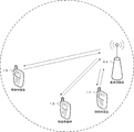
- FIG. 1 is a conceptual diagram of the wireless communication system of the present embodiment.
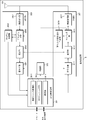
- the radio communication system includes mobile station apparatuses 1 A to 1 C and a base station apparatus 3.
- the mobile station apparatuses 1A to 1C are referred to as the mobile station apparatus 1.
- the following uplink physical channels are used in uplink radio communication from the mobile station apparatus 1 to the base station apparatus 3.
- the uplink physical channel is used for transmitting information output from an upper layer.
- -PUCCH Physical Uplink Control Channel
- PUSCH Physical Uplink Shared Channel
- PRACH Physical Random Access Channel
- the PUCCH is used for transmitting uplink control information (Uplink Control Information: UCI).
- UCI Uplink Control Information
- the uplink control information includes HARQ-ACK (HARQ feedback, response information) for downlink data (Downlink-Shared Channel: DL-SCH).
- the PUSCH is used to transmit uplink data (Uplink-Shared Channel: UL-SCH).
- the PUSCH may be used for transmitting uplink control information together with uplink data.
- PUSCH may be used to transmit only uplink control information.
- PRACH is used to transmit a random access preamble.
- the main purpose of the PRACH is that the mobile station device 1 synchronizes with the base station device 3 in the time domain.
- uplink physical signals are used in uplink wireless communication.
- the uplink physical signal is not used for transmitting information output from the upper layer, but is used by the physical layer.
- UL RS Uplink Reference Signal
- DMRS Demodulation Reference Signal
- SRS Sounding Reference Signal
- DMRS is related to transmission of PUSCH or PUCCH.
- DMRS is time-multiplexed with PUSCH or PUCCH.
- Base station apparatus 3 performs demodulation processing of PUSCH or PUCCH using DMRS.
- transmitting both PUSCH and DMRS is also simply referred to as transmitting PUSCH.
- transmitting both PUCCH and DMRS is also simply referred to as transmitting PUCCH.
- SRS is not related to PUSCH or PUCCH transmission.
- the base station apparatus 3 uses SRS to measure the uplink channel state.
- a symbol in which SRS is transmitted is also referred to as a sounding reference symbol. Details of the SRS will be described later.
- the following downlink physical channels are used in downlink radio communication from the base station apparatus 3 to the mobile station apparatus 1.
- the downlink physical channel is used for transmitting information output from an upper layer.
- PBCH Physical Broadcast Channel
- PCFICH Physical Control Format Indicator Channel
- PHICH Physical Hybrid automatic repeat request Indicator Channel
- PDCCH Physical Downlink Control Channel
- EPDCCH enhanced Physical Downlink Control Channel
- PDSCH Physical Downlink Shared Channel
- PMCH Physical Multicast Channel
- the PBCH is used to broadcast system information (master information block, Broadcast Channel: BCH) commonly used in the mobile station apparatus 1.
- BCH Broadcast Channel
- PBCH is transmitted at intervals of 40 ms.
- the mobile station apparatus 1 performs blind detection (blind detection) at 40 ms intervals.
- the PBCH is retransmitted at 10 ms intervals.
- PCFICH is used to transmit information indicating a region (OFDM symbol) reserved for transmission of PDCCH. This information is called CFI (Control (Format Indicator).
- CFI Control (Format Indicator).
- the number of OFDM symbols used for PDCCH (DCI) transmission in a certain subframe is the same as the CFI value transmitted in the PCFICH of the certain subframe. is there.
- the cell bandwidth is 10 physical resource blocks or less than 10 physical resource blocks
- the number of OFDM symbols used for transmission of PDCCH (DCI) is the value of CFI transmitted by PCFICH of the certain subframe. One more than.
- the “number of OFDM symbols used for PDCCH (DCI) transmission” is also referred to as “DCI span”.
- the span of DCI for a certain cell is determined based on the CFI transmitted by PCFICH of the certain subframe.
- PHICH is used to transmit a HARQ indicator (HARQ feedback, response information) indicating HARQ-ACK for uplink data (Uplink Shared Channel: UL-SCH) received by the base station apparatus 3.
- HARQ indicator HARQ feedback, response information
- uplink data Uplink Shared Channel: UL-SCH
- the mobile station apparatus 1 receives a HARQ indicator indicating ACK
- the corresponding uplink data is not retransmitted.
- the mobile station apparatus 1 receives a HARQ indicator indicating NACK
- the corresponding uplink data is retransmitted.
- the PDCCH and EPDCCH are used to transmit downlink control information (Downlink Control Information: DCI).
- the downlink control information is also referred to as a DCI format.
- the downlink control information includes a downlink grant (also referred to as downlink assignment; or downlink assignment “downlink assignment”) and an uplink grant (uplink grant).
- the downlink grant is downlink control information used for scheduling a single PDSCH within a single cell.
- the downlink grant is used for scheduling the PDSCH in the same subframe as the subframe in which the downlink grant is transmitted.
- the uplink grant is downlink control information used for scheduling a single PUSCH in a single cell.
- the uplink grant is used for scheduling a single PUSCH in a subframe that is four or more times after the subframe in which the uplink grant is transmitted.
- PDSCH is used to transmit downlink data (Downlink Shared Channel: DL-SCH).
- PMCH is used to transmit a multicast channel (Multicast Channel: MCH).
- MCH Multicast Channel
- the following downlink physical signals are used in downlink wireless communication.
- the downlink physical signal is not used for transmitting information output from the upper layer, but is used by the physical layer.
- SS Synchronization signal
- DL RS Downlink Reference Signal
- the synchronization signal is used by the mobile station apparatus 1 to synchronize the downlink frequency domain and time domain.
- the downlink reference signal is used by the mobile station device 1 to correct the propagation path of the downlink physical channel.
- the downlink reference signal is used for the mobile station apparatus 1 to calculate downlink channel state information.
- the downlink physical channel and the downlink physical signal are collectively referred to as a downlink signal.
- the uplink physical channel and the uplink physical signal are collectively referred to as an uplink signal.
- the downlink physical channel and the uplink physical channel are collectively referred to as a physical channel.
- the downlink physical signal and the uplink physical signal are collectively referred to as a physical signal.
- Physical channels and physical signals are not transmitted across multiple cells.
- the physical channel and the physical signal are transmitted in any one cell.
- BCH, UL-SCH and DL-SCH are transport channels.
- a channel used in a medium access control (Medium Access Control: MAC) layer is referred to as a transport channel.
- a transport channel is also referred to as a transport block.
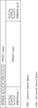
- FIG. 2 is a diagram illustrating a schematic configuration of a radio frame according to the present embodiment.
- Each of the plurality of cells has the same radio frame configuration.
- Each radio frame is 10 ms long.
- Each radio frame is composed of 10 subframes.
- Each subframe is 1 ms long and is defined by two consecutive slots.
- the i-th subframe in the radio frame is composed of a (2 ⁇ i) th slot and a (2 ⁇ i + 1) th slot.
- Each of the slots is 0.5 ms long.
- FIG. 3 is a diagram showing the configuration of the slot according to the present embodiment.
- the physical signal or physical channel transmitted in each of the slots is represented by a resource grid.
- the resource grid is defined by a plurality of subcarriers and a plurality of OFDM symbols.
- the resource grid is defined by a plurality of subcarriers and a plurality of SC-FDMA symbols.
- the number of subcarriers constituting one slot depends on the uplink bandwidth or downlink bandwidth of the cell.
- the number of OFDM symbols or SC-FDMA symbols constituting one slot is seven.
- Each element in the resource grid is called a resource element.
- the resource element includes a subcarrier number k (0, 1,%) And an OFDM symbol number l (0, 1,..., 6) or an SC-FDMA symbol number l (0, 0,. 1,..., 6) for identification.
- the resource block is used to express mapping of a certain physical channel (such as PDSCH or PUSCH) to a resource element.
- resource blocks virtual resource blocks and physical resource blocks are defined.
- a physical channel is first mapped to a virtual resource block. Thereafter, the virtual resource block is mapped to the physical resource block.
- One physical resource block is defined by 7 consecutive OFDM symbols or SC-FDMA symbols in the time domain and 12 consecutive subcarriers in the frequency domain. Therefore, one physical resource block is composed of (7 ⁇ 12) resource elements.
- One physical resource block corresponds to one slot in the time domain and corresponds to 180 kHz in the frequency domain. Physical resource blocks are numbered from 0 in the frequency domain.
- FIG. 4 is a diagram illustrating an example of the arrangement of physical channels and physical signals in the downlink subframe of the present embodiment.
- the base station apparatus 3 can transmit a downlink physical channel (PBCH, PCFICH, PHICH, PDCCH, EPDCCH, PDSCH) and a downlink physical signal (synchronization signal, downlink reference signal) in the downlink subframe.
- PBCH is transmitted only in subframe 0 in the radio frame.
- the synchronization signal is arranged only in subframes 0 and 5 in the radio frame.
- the downlink reference signal is arranged in resource elements distributed in the frequency domain and the time domain. For simplicity of explanation, the downlink reference signal is not shown in FIG.
- PCFICH is arranged in the first OFDM symbol of the first slot.
- the PHICH is arranged in the first OFDM symbol of the first slot.
- a plurality of PDCCHs are frequency and time multiplexed.
- PDCCH is arranged in order from the first OFDM symbol of the first slot.
- the DCI span is determined based on the CFI.
- the base station device 3 may transmit information indicating the start position of the OFDM symbol in which the EPDCCH is arranged in the first slot of the subframe to the mobile station device 1.
- Information indicating the start position of the OFDM symbol in which the EPDCCH is arranged is referred to as “epdcch-Start”.
- the start position of the OFDM symbol in which the EPDCCH is arranged is also referred to as “the start position for the EDCCCCH resource element mapping” and “the start position of the resource element to which the EPDCCH is mapped”.
- the base station apparatus 3 sets epdcch-Start for each cell.
- a specific transmission mode for example, transmission mode 10
- the base station apparatus 3 may set different epdcch-Start for each of the EPDCCH areas. Good. The transmission mode will be described later.
- the mobile station apparatus 1 determines the start position of the OFDM symbol in which the EPDCCH is arranged in the first slot of the subframe based on the received epdcch-Start. When the mobile station apparatus 1 has not received epdcch-Start, the mobile station apparatus 1 determines the start position of the OFDM symbol in which the EPDCCH is arranged in the first slot of the subframe based on the DCI span. For example, when the DCI span is 3 (when the PDCCH region is composed of the first, second and third OFDM symbols of the first slot of the subframe), the mobile station apparatus 1 It is determined that the EPDCCH is arranged from the fourth OFDM symbol in the first slot of the frame.
- a plurality of PDSCHs are frequency and space multiplexed.
- the start position of the OFDM symbol where the PDSCH is arranged will be described later.
- PDCCH is time multiplexed with PDSCH and EPDCCH.
- the EPDCCH is frequency-multiplexed with the PDSCH.
- the PDCCH is mapped to one PDCCH candidate (candidate).
- One PDCCH candidate is composed of one or a plurality of continuous CCEs (Control Channel Element).
- the CCE is arranged in the PDCCH region.
- FIG. 5 is a diagram showing a method of mapping the PDCCH of this embodiment to resource elements.
- One CCE is used to transmit 36 modulation symbols (complex-valued symbol: complex-valued symbol).
- One CCE is composed of nine mini-CCEs.
- One mini-CCE is composed of four modulation symbols.
- the base station apparatus 3 maps one mini-CCE to one resource element group.
- One resource element group is composed of four consecutive resource elements in the frequency domain. That is, one modulation symbol is mapped to one resource element.
- the base station apparatus 3 interleaves CCEs in mini-CCE units. Next, the base station apparatus 3 cyclically shifts the interleaved mini-CCE.
- the value of the cyclic shift is the value of physical layer cell identity (Physical layer Cell Identity: PCI). That is, different values of cyclic shift are performed between cells having different physical layer cell identifiers. Thereby, the interference of PDCCH between cells can be randomized.
- the mobile station device 1 can detect the physical layer cell identity from the synchronization signal. Further, the base station device 3 can transmit a handover command including information indicating the physical layer cell identity to the mobile station device 1.
- the base station apparatus 3 maps the cyclic shifted mini-CCE to the resource element group in the PDCCH region.
- the base station apparatus 3 maps the PDCCH mini-CCE to resource element groups other than the resource element group to which PHICH and PCFICH are mapped.
- the EPDCCH is mapped to one EPDCCH candidate (candidate).
- One EPDCCH candidate is composed of one or a plurality of consecutive ECCEs (enhanced Control Control Channel Control Element).
- a plurality of EPDCCH regions may be defined for a single mobile station apparatus.
- the base station device 3 transmits information indicating one or a plurality of physical resource blocks constituting the EPDCCH region to the mobile station device 1.
- ECCE is defined for each of the EPDCCH regions.
- a single ECCE is arranged in a single EPDCCH region.
- the EPDCCH region is also referred to as an EPDCCH set.
- FIG. 6 is a diagram showing a method for mapping the EPDCCH of this embodiment to resource elements.
- One ECCE is used to transmit a plurality of modulation symbols (complex value symbols: complex-valued symbol).
- One ECCE is composed of a plurality of mini-ECCEs.
- One mini-ECCE is composed of a plurality of modulation symbols.
- the base station apparatus 3 maps one mini-ECCE to one enhanced resource element group.
- a plurality of resource elements constituting two physical resource blocks (one physical resource block in the first slot and one physical resource block in the second slot) that are continuous in the time domain in the subframe are 16 Divided into enhanced resource element groups.
- One enhanced resource element group is composed of nine resource elements.
- ECCE (ECCE0, ECCE1, ECCE2, and ECCE3) for EPDCCH set 1 is arranged in the resource element of EPDCCH set 1.
- ECCE (ECCE0, ECCE1, ECCE2, and ECCE3) for EPDCCH set 2 is arranged in the resource element of EPDCCH set 2.
- ECCE numbers corresponding to the respective EPDCCH sets are assigned from 0.
- the search space is described below.
- the search space is composed of a set of PDCCH candidates or EPDCCH candidates.
- FIG. 7 is a diagram illustrating an example of the configuration of the search space according to the present embodiment.
- the PDCCH area includes CSS (Common Search-Space) and USS (Use-equipment-specific Search Space). CSS is not configured as a secondary cell. CSS is configured only in the primary cell.
- USS is configured in each EPDCCH set. CSS is defined by resources common to a plurality of mobile station apparatuses 1. The USS is defined independently for each mobile station apparatus 1.
- the mobile station apparatus 1 monitors the PDCCH in the CSS of the primary cell.
- the mobile station apparatus 1 monitors PDCCH or EPDCCH in one of the PDCCH region USS and the EPDCCH set USS in a certain subframe.
- the base station device 3 transmits to the mobile station device 1 information indicating for each subframe whether the mobile station device 1 monitors the USS of the PDCCH region or the USS of the EPDCCH. Based on the received information, the mobile station apparatus 1 determines whether to monitor the PDCCH with the USS in the PDCCH region or the EPDCCH with the USS of the EPDCCH set in a certain subframe. If the mobile station apparatus 1 has not received the information, the mobile station apparatus 1 monitors the PDCCH using the USS in the PDCCH region in all subframes.
- the base station device 3 sets a transmission mode for the mobile station device 1 via the upper layer signal.
- the base station apparatus 3 sets a transmission mode for each cell.
- the mobile station apparatus 1 sets a transmission mode based on the received upper layer signal.
- the mobile station apparatus 1 is configured to receive a PDSCH data transmission signaled via the PDCCH / EPDCCH according to one of the transmission modes 1 to 10 via the upper layer signal. Is done.
- the mobile station apparatus 1 sets the transmission mode 1 or the transmission mode 2 when the transmission mode is not set via the upper layer signal.
- the mobile station apparatus 1 sets the transmission mode 1 when a single antenna port is used for PBCH transmission and the transmission mode is not set via a higher layer signal.
- the mobile station apparatus 1 sets the transmission mode 2 when a plurality of antenna ports are used for PBCH transmission and the transmission mode is not set via the upper layer signal.
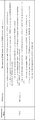
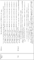
- the mobile station apparatus 1 When the mobile station apparatus 1 is set to decode the PDCCH by the higher layer, the mobile station apparatus 1 decodes the PDCCH and the PDSCH corresponding to the PDCCH based on each of the combinations defined in the table of FIG. For example, the mobile station apparatus 1 set to the transmission mode 7 monitors the PDCCH with the DCI format 1A by CSS and USS, and based on the detected DCI format 1A, the single antenna port (port 0) or the transmission PDSCH transmitted by the diversity method is received. For example, the mobile station apparatus 1 set to the transmission mode 7 monitors the PDCCH with the DCI format 1 by the USS, and is transmitted through the single antenna port (port 5) based on the detected DCI format 1. Receive PDSCH.
- the mobile station apparatus 1 When the mobile station apparatus 1 is set to decode the EPDCCH by the upper layer, the mobile station apparatus 1 decodes the EPDCCH and the PDSCH corresponding to the EPDCCH based on each of the combinations defined in the table of FIG. For example, the mobile station apparatus 1 set to the transmission mode 7 monitors the EPDCCH with the DCI format 1A by the USS, and based on the detected DCI format 1A, the single antenna port (port 0) or the transmission diversity system The PDSCH transmitted in is received. For example, the mobile station apparatus 1 set to the transmission mode 7 monitors the EPDCCH with the DCI format 1 by the USS, and is transmitted through the single antenna port (port 5) based on the detected DCI format 1. Receive PDSCH.
- start position of the OFDM symbol where the PDSCH is arranged is also referred to as “start position for PDSCH resource element mapping” and “the start position of the resource element / OFDM symbol to which the PDSCH is mapped”.
- FIGS. 10 to 20 are diagrams for explaining the start position of the OFDM symbol to which the PDSCH is mapped.
- the mobile station apparatus 1 and the base station apparatus 3 determine the OFDM symbol start position l DataStart to which the PDSCH for each cell is mapped, based on FIGS. 10 to 20. For example, when the transmission mode 10 is set and the PDSCH scheduled in the DCI format 1A is transmitted and received, the mobile station apparatus 1 and the base station apparatus 3 are any one of FIG. 12 to FIG. Using an example, the start position l DataStart of the OFDM symbol to which the PDSCH for each cell is mapped is determined.
- the mobile station apparatus 1 and the base station apparatus 3 are any one of FIG. 17 to FIG.
- the start position l DataStart of the OFDM symbol to which the PDSCH for each cell is mapped is determined.
- FIG. 10 is a diagram for explaining the start position of the OFDM symbol to which the PDSCH is mapped for the mobile station apparatus 1 in which any one of the transmission modes 1 to 9 is set for a certain cell.
- the mobile station apparatus 1 in which any one of the transmission modes 1 to 9 is set monitors the DCI format 1, 1A, 1B, 1C, 1D, 2, 2A, 2B, or 2C.
- the DCI format 1C is used for PCH (Paging Channel), random access response, system information block scheduling, and the like.
- the DCI format 1C is transmitted only by CSS.
- the carrier indicator field is included in the DCI format.
- a carrier indicator is mapped to the carrier indicator field.
- the carrier indicator is used to indicate the cell to which the DCI format corresponds.
- the base station device 3 can set for each cell whether or not the carrier indicator field is included in the DCI format transmitted in the cell.
- the base station apparatus 3 can set a cell to which a DCI format used for scheduling of the secondary cell is transmitted for each secondary cell.
- the DCI format used for primary cell scheduling is always transmitted in the primary cell.
- the base station apparatus 3 sets pdsch-Start for each cell scheduled by the DCI format of another cell. Note that the setting of the carrier indicator and the setting of pdsch-Start may be different for each mobile station apparatus 1 that communicates using the same cell.
- the mobile station device 1 is not set in the carrier indicator field for the mobile station device 1 in which any one of the transmission modes 1 to 9 is set, or the mobile station device 1 is in the PDSCH.
- Mobile station apparatus 1 detects DCI format 1, 1A, 1B, 1C, 1D, 2, 2A, 2B, or 2C on EPDCCH.
- l DataStart is given by the upper layer parameter epdcch-Start.
- the mobile station device 1 is not set in the carrier indicator field for the mobile station device 1 in which any one of the transmission modes 1 to 9 is set, or the mobile station device 1 is in the PDSCH.
- the PDCCH / EPDCCH corresponding to the PDSCH are received in the same cell, and the mobile station apparatus 1 receives the DCI format 1, 1A, 1B, 1C, 1D, 2, 2A, 2B, or 2C on the PDCCH. If detected, lDataStart is given by the DCI span given by the CFI of the cell.
- the mobile station device 1 is not set in the carrier indicator field for the mobile station device 1 in which any one of the transmission modes 1 to 9 is set, or the mobile station device 1 is in the PDSCH.
- the PDCCH / EPDCCH corresponding to the PDSCH are received in the same cell, and the mobile station apparatus 1 receives the DCI format 1, 1A, 1B, 1C, 1D, 2, 2A, 2B, or 2C on the EPDCCH. If this is the case, and if the value for the upper layer parameter epdcch-Start for the cell is not set by the upper layer, lDataStart is given by the DCI span given by the CFI of the cell.
- FIG. 11 is a diagram for explaining the start position of the OFDM symbol to which the PDSCH scheduled by the DCI format 1C is mapped for the mobile station apparatus 1 in which the transmission mode 10 is set for a certain cell.
- Transmission mode 10 is set, and lDataStart is given to the mobile station apparatus 1 that receives the PDSCH scheduled in the DCI format 1C by the DCI span given by the CFI of the cell.
- FIG. 12 is a diagram for explaining a first example of the start position of the OFDM symbol to which the PDSCH scheduled by the DCI format 1A is mapped for the mobile station apparatus 1 in which the transmission mode 10 is set for a certain cell. is there.
- the mobile station apparatus 1 for the mobile station apparatus 1 that receives the PDSCH scheduled in the DCI format 1A in which the transmission mode 10 is set, the mobile station apparatus 1 has not set the carrier indicator field for the cell.
- the mobile station apparatus 1 receives the PDSCH and the PDCCH / EPDCCH corresponding to the PDSCH in the same cell, and the mobile station apparatus 1 detects the DCI format 1A on the EPDCCH, and the cell
- the value for the upper layer parameter epdcch-Start for is set by the upper layer
- lDataStart is given by the upper layer parameter epdcch-Start for the cell or epdcch-Start for the EPDCCH set that has received the EPDCCH.
- transmission mode 10 is set, and for mobile station apparatus 1 that receives PDSCH scheduled in DCI format 1A, mobile station apparatus 1 does not have a carrier indicator field set for a cell.
- the mobile station apparatus 1 receives the PDSCH and the PDCCH / EPDCCH corresponding to the PDSCH in the same cell, and when the mobile station apparatus 1 detects the DCI format 1A on the PDCCH, the CFI of the cell LDataStart is given by the DCI span given by.
- the mobile station apparatus 1 for the mobile station apparatus 1 that receives the PDSCH scheduled in the DCI format 1A in which the transmission mode 10 is set, the mobile station apparatus 1 has not set the carrier indicator field for the cell.
- the mobile station apparatus 1 receives the PDSCH and the PDCCH / EPDCCH corresponding to the PDSCH in the same cell, and the mobile station apparatus 1 detects the DCI format 1A on the EPDCCH, and the cell If the value for the upper layer parameter epdcch-Start is not set by the upper layer, l DataStart is given by the DCI span given by the CFI of the cell.
- FIG. 13 is a diagram for explaining a second example of the start position of the OFDM symbol to which the PDSCH scheduled by the DCI format 1A is mapped for the mobile station apparatus 1 in which the transmission mode 10 is set for a certain cell. is there.
- the mobile station apparatus 1 when the transmission mode 10 is set and the mobile station apparatus 1 receives the PDSCH scheduled in the DCI format 1A, the mobile station apparatus 1 is set with the carrier indicator field for the cell.
- the mobile station apparatus 1 receives the PDSCH and the PDCCH / EPDCCH corresponding to the PDSCH in different cells, l DataStart is given by the higher layer parameter pdsch-Start for the cell receiving the PDSCH.
- the mobile station apparatus 1 For the mobile station apparatus 1 that receives the PDSCH scheduled in the DCI format 1A in which the transmission mode 10 is set, the mobile station apparatus 1 has not set the carrier indicator field for the cell.
- the mobile station apparatus 1 receives the PDSCH and the PDCCH / EPDCCH corresponding to the PDSCH in the same cell, and the value of the upper layer parameter 'PDSCH starting position for PDSCH RE mapping' for the cell is 0, 1 In the case of 2, 3, or 4, lDataStart is given by the higher layer parameter 'PDSCH starting position for PDSCH RE mapping' corresponding to the DCI format 1A.
- the mobile station apparatus 1 For the mobile station apparatus 1 that receives the PDSCH scheduled in the DCI format 1A in which the transmission mode 10 is set, the mobile station apparatus 1 has not set the carrier indicator field for the cell. Alternatively, the mobile station apparatus 1 receives the PDSCH and the PDCCH / EPDCCH corresponding to the PDSCH in the same cell, and the value of the upper layer parameter 'PDSCH starting position for PDSCH RE mapping' for the cell is 5. In some cases, lDataStart is given by the DCI span given by the cell's CFI.
- the base station apparatus 3 may set an upper layer parameter 'PDSCH' starting 'position' for 'PDSCH' RE'mapping 'for each cell. If the base station apparatus 3 does not set the upper layer parameter 'PDSCH starting position for PDSCH RE mapping' for the cell, the mobile station device 1 sets the upper layer parameter 'PDSCH starting position for PDSCH RE mapping' for the cell to 5. .
- the value of the upper layer parameter 'PDSCH starting position for PDSCH RE mapping' for the cell is 5
- the value of the upper layer parameter 'PDSCH'starting position for PDSCH RE mapping' for the cell is set by the upper layer. If not.
- the base station apparatus 3 sets an upper layer parameter in the mobile station apparatus 1 via an upper layer signal.
- the base station device 3 transmits an upper layer signal indicating the value of the upper layer parameter to the mobile station device 1.
- the mobile station apparatus 1 sets an upper layer parameter based on the received upper layer signal.
- epdcch-Start can take values from 0 to 5.
- the mobile station apparatus 1 may set the upper layer parameter epdcch-Start for the cell to 5 when the upper layer parameter epdcch-Start for the cell is not set by the base station apparatus 3.
- the base station apparatus 3 sets an upper layer parameter in the mobile station apparatus 1 via an upper layer signal.
- the base station device 3 transmits an upper layer signal indicating the value of the upper layer parameter to the mobile station device 1.
- the mobile station apparatus 1 sets an upper layer parameter based on the received upper layer signal.
- FIG. 14 is a diagram for explaining a third example of the start position of the OFDM symbol to which the PDSCH scheduled by the DCI format 1A is mapped for the mobile station apparatus 1 in which the transmission mode 10 is set for a certain cell. is there.
- the mobile station apparatus 1 when the transmission mode 10 is set and the mobile station apparatus 1 that receives the PDSCH scheduled in the DCI format 1A receives the PDSCH, the mobile station apparatus 1 is set with the carrier indicator field for the cell.
- the mobile station apparatus 1 receives the PDSCH and the PDCCH / EPDCCH corresponding to the PDSCH in different cells, l DataStart is given by the higher layer parameter pdsch-Start for the cell receiving the PDSCH.
- the mobile station device 1 is not set to the carrier indicator field for the mobile station device 1 that receives the PDSCH scheduled in the DCI format 1A when the transmission mode 10 is set.
- the mobile station apparatus 1 receives the PDSCH and the PDCCH / EPDCCH corresponding to the PDSCH in the same cell, and the mobile station apparatus 1 detects the DCI format 1A on the EPDCCH, and the cell If the value of the upper layer parameter 'PDSCH starting position for PDSCH RE mapping' is 0, 1, 2, 3, or 4, the upper layer parameter 'PDSCH starting position for PDSCH RE mapping' corresponding to DCI format 1A L DataStart is given by '.
- the mobile station device 1 is not set to the carrier indicator field for the mobile station device 1 that receives the PDSCH scheduled in the DCI format 1A when the transmission mode 10 is set.
- the mobile station apparatus 1 receives the PDSCH and the PDCCH / EPDCCH corresponding to the PDSCH in the same cell, and when the mobile station apparatus 1 detects the DCI format 1A on the PDCCH, the CFI of the cell LDataStart is given by the DCI span given by.
- the mobile station device 1 is not set to the carrier indicator field for the mobile station device 1 that receives the PDSCH scheduled in the DCI format 1A when the transmission mode 10 is set.
- the mobile station apparatus 1 receives the PDSCH and the PDCCH / EPDCCH corresponding to the PDSCH in the same cell, and the mobile station apparatus 1 detects the DCI format 1A on the EPDCCH, and the cell
- the value of the upper layer parameter 'PDSCH starting position for PDSCH RE mapping' for 5 is 5, l DataStart is given by the DCI span given by the CFI of the cell.
- FIG. 15 is a diagram for explaining a fourth example of the start position of the OFDM symbol to which the PDSCH scheduled by the DCI format 1A is mapped for the mobile station apparatus 1 in which the transmission mode 10 is set for a certain cell. is there.
- the mobile station apparatus 1 when the transmission mode 10 is set and the mobile station apparatus 1 receives the PDSCH scheduled in the DCI format 1A, the mobile station apparatus 1 is set with the carrier indicator field for the cell.
- the mobile station apparatus 1 receives the PDSCH and the PDCCH / EPDCCH corresponding to the PDSCH in different cells, l DataStart is given by the higher layer parameter pdsch-Start for the cell receiving the PDSCH.
- the mobile station device 1 is not set to the carrier indicator field for the cell with respect to the mobile station device 1 that receives the PDSCH scheduled in the DCI format 1A when the transmission mode 10 is set.
- the mobile station apparatus 1 receives the PDSCH and the PDCCH / EPDCCH corresponding to the PDSCH in the same cell, and the mobile station apparatus 1 detects the DCI format 1A in the USS, and the cell If the value of the upper layer parameter 'PDSCH starting position for PDSCH RE mapping' is 0, 1, 2, 3, or 4, the upper layer parameter 'PDSCH starting position for PDSCH RE mapping' corresponding to DCI format 1A L DataStart is given by
- transmission mode 10 is set, and for mobile station apparatus 1 that receives PDSCH scheduled in DCI format 1A, mobile station apparatus 1 does not have a carrier indicator field set for a cell.
- the mobile station apparatus 1 receives the PDSCH and the PDCCH / EPDCCH corresponding to the PDSCH in the same cell, and when the mobile station apparatus 1 detects the DCI format 1A by CSS, the CFI of the cell LDataStart is given by the DCI span given by.
- the mobile station device 1 is not set to the carrier indicator field for the cell with respect to the mobile station device 1 that receives the PDSCH scheduled in the DCI format 1A when the transmission mode 10 is set.
- the mobile station apparatus 1 receives the PDSCH and the PDCCH / EPDCCH corresponding to the PDSCH in the same cell, and the mobile station apparatus 1 detects the DCI format 1A in the USS, and the cell
- the value of the upper layer parameter 'PDSCH starting position for PDSCH RE mapping' for 5 is 5, l DataStart is given by the DCI span given by the CFI of the cell.
- FIG. 16 is a diagram for explaining a fifth example of the start position of the OFDM symbol to which the PDSCH scheduled by the DCI format 1A is mapped for the mobile station apparatus 1 in which the transmission mode 10 is set for a certain cell. is there.
- the mobile station device 1 is not set to the carrier indicator field for the cell with respect to the mobile station device 1 that receives the PDSCH scheduled in the DCI format 1A when the transmission mode 10 is set.
- the mobile station apparatus 1 receives the PDSCH and the PDCCH / EPDCCH corresponding to the PDSCH in the same cell, and the value of the upper layer parameter 'PDSCH starting position for PDSCH RE mapping' for the cell is 0, 1 In the case of 2, 3, or 4, lDataStart is given by the higher layer parameter 'PDSCH starting position for PDSCH RE mapping' corresponding to the DCI format 1A.
- transmission mode 10 is set, and for mobile station apparatus 1 that receives a PDSCH scheduled in DCI format 1A, mobile station apparatus 1 does not have a carrier indicator field set for a cell.
- the mobile station apparatus 1 receives the PDSCH and the PDCCH / EPDCCH corresponding to the PDSCH in the same cell, and the mobile station apparatus 1 detects the DCI format 1A on the EPDCCH, and the cell If the value of the upper layer parameter 'PDSCH starting position for PDSCH RE mapping' for is 5 and if the value for the upper layer parameter epdcch-Start for the cell is set by the upper layer, the upper layer for the cell EP receiving layer parameter epdcch-Start or EPDCCH L DataStart is given by epdcch-Start for the DCCH set.
- the mobile station device 1 is not set to the carrier indicator field for the cell with respect to the mobile station device 1 that receives the PDSCH scheduled in the DCI format 1A when the transmission mode 10 is set.
- the mobile station apparatus 1 receives the PDSCH and the PDCCH / EPDCCH corresponding to the PDSCH in the same cell, and the mobile station apparatus 1 detects the DCI format 1A on the PDCCH, and the cell
- the value of the upper layer parameter 'PDSCH starting position for PDSCH RE mapping' for 5 is 5, l DataStart is given by the DCI span given by the CFI of the cell.
- transmission mode 10 is set, and for mobile station apparatus 1 that receives a PDSCH scheduled in DCI format 1A, mobile station apparatus 1 does not have a carrier indicator field set for a cell.
- the mobile station apparatus 1 receives the PDSCH and the PDCCH / EPDCCH corresponding to the PDSCH in the same cell, and the mobile station apparatus 1 detects the DCI format 1A on the EPDCCH, and the cell If the value of the upper layer parameter 'PDSCH starting position for PDSCH RE mapping' for is 5 and the value for the upper layer parameter epdcch-Start for the cell is not set by the upper layer, the CFI of the cell l datastart is provided by the span of the given DCI by .
- FIG. 17 is a diagram for explaining a first example of the start position of the OFDM symbol to which the PDSCH scheduled by the DCI format 2D is mapped for the mobile station apparatus 1 in which the transmission mode 10 is set for a certain cell. is there.
- the base station apparatus 3 can set four sets of upper layer parameters for the DCI format 2D in the mobile station apparatus 1.
- the set of upper layer parameters includes at least ‘PDSCH starting position for PDSCH RE mapping’ and ⁇ MBSFN subframe configuration for PDSCH RE mapping '.
- the base station device 3 transmits information indicating one of the four sets of higher layer parameters to the mobile station device 1.
- Information indicating one of the four sets of higher layer parameters is included in the DCI format 2D. That is, “PDSCH” starting “position” for “PDSCH” RE “mapping” and “MBSFN” subframe “configuration” for “PDSCH” RE “mapping” are determined from the DCI format 2D.
- the DCI span is 1 or 2.
- 'MBSFN'subframe'configuration'for'PDSCH'RE'mapping' is a parameter used only for PDSCH resource element mapping.
- an upper layer parameter 'MBSFN' subframe 'configuration' indicating whether the subframe is an MBSFN subframe is defined separately from 'MBSFN' subframe 'configuration' for 'PDSCH' RE'mapping '.
- 'MBSFN' subframe 'configuration' and 'MBSFN' subframe 'configuration' for 'PDSCH' RE'mapping ' are bitmaps, and one bit of the bitmap corresponds to one subframe.
- the bitmap is used periodically. For example, a subframe corresponding to a bit having a value of 1 is a subframe indicated by 'MBSFN'subframe'configuration' or 'MBSFN'subframe'configuration'for'PDSCH'RE'mapping'.
- the subframe indicated by 'MBSFN' subframe 'configuration is an MBSFN subframe.
- a subframe not designated by 'MBSFN' subframe 'configuration' is a non-MBSFN subframe.
- the base station apparatus 3 sets a bitmap of MBSFN subframe configuration to MBSFN subframe configuration for PDSCH RE mapping.
- the base station device 3 does not set “PDSCH” starting “position” for “PDSCH” RE “mapping”
- the mobile station device 1 sets 5 to “PDSCH” starting “position” for “PDSCH” RE “mapping”.
- the transmission mode 10 is set, and the mobile station apparatus 1 that receives the PDSCH scheduled in the DCI format 2D receives the 'PDSCH starting position for determined from the DCI format 2D for the cell that receives the PDSCH.
- the value of “PDSCH RE mapping” is 0, 1, 2, 3, or 4
- the value of “PDSCH starting position for PDSCH RE mapping” is set in l ′ DataStart .
- the 'PDSCH starting position for determined from the DCI format 2D for the cell that receives the PDSCH is the case where the value of PDSCH RE mapping 'is 5, and the case where the mobile station apparatus 1 is set with the carrier indicator field for the cell, and the mobile station apparatus 1 corresponds to the PDSCH and the PDSCH.
- l ′ DataStart is given by the higher layer parameter pdsch-Start for the cell receiving PDSCH.
- the 'PDSCH starting position for determined from the DCI format 2D for the cell that receives the PDSCH is a case where the value of PDSCH RE mapping 'is 5, and the mobile station device 1 has not set the carrier indicator field for the cell, or the mobile station device 1 has PDSCH / PDSCH / PDSCH corresponding to the PDSCH /
- the EPDCCH is received by the same cell, and when the mobile station apparatus 1 detects the DCI format 2D by the EPDCCH, and a value for the upper layer parameter epdcch-Start for the cell is set by the upper layer.
- the upper layer parameter epdcch for the cell -Start or l' DataStart is given by epdcch-Start for the EPDCCH set that has received the EPDCCH.
- the transmission mode 10 is set, and the mobile station apparatus 1 that receives the PDSCH scheduled in the DCI format 2D receives the 'PDSCH starting position for determined from the DCI format 2D for the cell receiving the PDSCH.
- the mobile station apparatus 1 that receives the PDSCH scheduled in the DCI format 2D receives the 'PDSCH starting position for determined from the DCI format 2D for the cell receiving the PDSCH.
- the value of PDSCH RE mapping 'is 5 the mobile station device 1 has not set the carrier indicator field for the cell, or the mobile station device 1 has PDSCH / PDSCH / PDSCH corresponding to the PDSCH /
- EPDCCH is received in the same cell, and mobile station apparatus 1 detects DCI format 2D on PDCCH, l ′ DataStart is given by the DCI span given by the CFI of the cell.
- the transmission mode 10 is set, and the mobile station apparatus 1 that receives the PDSCH scheduled in the DCI format 2D receives the 'PDSCH starting position for determined from the DCI format 2D for the cell that receives the PDSCH.
- the value of PDSCH RE mapping 'is 5 and the mobile station device 1 has not set the carrier indicator field for the cell, or the mobile station device 1 has PDSCH / PDSCH / PDSCH corresponding to the PDSCH /
- the EPDCCH is received by the same cell, and the mobile station apparatus 1 detects the DCI format 2D by the EPDCCH, and the value for the upper layer parameter epdcch-Start for the cell is set by the upper layer. If not, given by the CFI of the cell L'DataStart is given by the span of DCI.
- Equation (1) when the subframe is indicated by the “MBSFN subframe configuration for PDSCH RE mapping” determined from the DCI format 2D for the cell that receives the PDSCH, l DataStart is given based on Equation (1). It is done. min (X, Y) is a function that outputs the smallest value among the input values (values in parentheses).
- the DCI format is determined from 2D 'MBSFN subframe configuration for PDSCH RE mapping' for the cell to receive the PDSCH, in addition when the sub-frame is indicated, set the value of l 'datastart to l datastart To do.
- One of the four upper layer parameters “PDSCH” starting “position” for “PDSCH” RE “mapping” for the DCI format 2D may be common to the upper layer parameter “PDSCH” starting “position” for “PDSCH” RE “mapping” for the DCI format 1A. Further, the four higher layer parameters ‘PDSCH starting position for PDSCH RE mapping 'for the DCI format 2D may be defined independently of the upper layer parameter' PDSCH starting position for PDSCH RE mapping 'for the DCI format 1A.
- FIG. 17 may be applied to the mobile station apparatus 1 that receives the PDSCH scheduled in the DCI format 1A in which the transmission mode 10 is set.
- one set of higher layer parameters can be set for the DCI format 1A.
- One of the four sets of upper layer parameters for DCI format 2D may be common with one set of upper layer parameters for DCI format 1A.
- one of the four sets of higher layer parameters for DCI format 2D may be defined independently of one set of higher layer parameters for DCI format 1A.
- FIG. 18 is a diagram for explaining a second example of the start position of the OFDM symbol to which the PDSCH scheduled by the DCI format 2D is mapped for the mobile station apparatus 1 in which the transmission mode 10 is set for a certain cell. is there.
- the 'PDSCH starting position for determined from the DCI format 2D for the cell that receives the PDSCH is set in l ′ DataStart .
- the transmission mode 10 is set, and the mobile station apparatus 1 that receives the PDSCH scheduled in the DCI format 2D is set to the 'PDSCH starting position for This is the case where the value of PDSCH RE mapping 'is 5, and the case where the mobile station apparatus 1 is set with the carrier indicator field for the cell, and the mobile station apparatus 1 corresponds to the PDSCH and the PDSCH.
- l ′ DataStart is given by the higher layer parameter pdsch-Start for the cell receiving PDSCH.
- the transmission mode 10 is set, and the 'PDSCH starting position for determined from the DCI format 2D for the cell that receives the PDSCH. This is a case where the value of PDSCH RE mapping 'is 5, and the mobile station device 1 has not set the carrier indicator field for the cell, or the mobile station device 1 has the PDCCH / PDSCH / PDSCH corresponding to the PDSCH.
- the 'PDSCH starting position for determined from the DCI format 2D for the cell that receives the PDSCH is a case where the value of PDSCH RE mapping 'is 5, and the mobile station device 1 has not set the carrier indicator field for the cell, or the mobile station device 1 has PDSCH / PDSCH / PDSCH corresponding to the PDSCH / If the EPDCCH is received in the same cell, and the value of the upper layer parameter 'PDSCH starting position for PDSCH RE mapping' for the DCI format 1A is 5, the DCI span given by the CFI of the cell l ' DataStart is given.
- the PDSCH when the PDSCH is scheduled by the DCI format 2D and the subframe is indicated by the “MBSFN subframe configuration for PDSCH RE mapping” determined from the DCI format 2D for the cell receiving the PDSCH, the PDSCH Is scheduled according to DCI format 1A, and subframes are indicated by 'MBSFN subframe configuration for PDSCH RE mapping' for DCI format 1A for cells receiving PDSCH, based on equation (1) l DataStart is given. 18, in other cases, sets the value of l 'datastart to l datastart.
- the PDSCH is scheduled by the DCI format 2D, and the subframe is indicated by“ MBSFN subframe configuration for PDSCH RE mapping ”determined from the DCI format 2D for the cell that receives the PDSCH.
- the subframe is indicated by“ MBSFN subframe configuration for PDSCH RE mapping ”determined from the DCI format 2D for the cell that receives the PDSCH.
- the subframe is indicated by“ MBSFN subframe configuration for PDSCH RE mapping ”determined from the DCI format 2D for the cell that receives the PDSCH.
- 'MBSFN subframe configuration for PDSCH RE mapping' for DCI format 1A for a cell that receives PDSCH "including.
- FIG. 19 is a diagram for explaining a third example of the start position of the OFDM symbol to which the PDSCH scheduled by the DCI format 2D is mapped for the mobile station apparatus 1 in which the transmission mode 10 is set for a certain cell. is there.
- the 'PDSCH starting position for determined from the DCI format 2D for the cell that receives the PDSCH is set in l ′ DataStart .
- the “PDSCH starting position for” determined from the DCI format 2D for the cell that receives the PDSCH. This is the case where the value of PDSCH RE mapping 'is 5, and the case where the mobile station apparatus 1 is set with the carrier indicator field for the cell, and the mobile station apparatus 1 corresponds to the PDSCH and the PDSCH.
- l ′ DataStart is given by the higher layer parameter pdsch-Start for the cell receiving PDSCH.
- the 'PDSCH starting position for determined from the DCI format 2D for the cell that receives the PDSCH This is a case where the value of PDSCH RE mapping 'is 5, and the mobile station device 1 has not set the carrier indicator field for the cell, or the mobile station device 1 has the PDCCH / PDSCH / PDSCH corresponding to the PDSCH.
- the EPDCCH is received in the same cell, and the mobile station apparatus 1 detects the DCI format 2D using the EPDCCH, and the upper layer parameter “PDSCH starting position for PDSCH RE mapping” for the DCI format 1A. If the value is 0, 1, 2, 3, or 4 The, l 'datastart is given by higher layers parameter' PDSCH starting position for PDSCH RE mapping ' corresponding to DCI format 1A.
- the 'PDSCH starting position for determined from the DCI format 2D for the cell that receives the PDSCH This is a case where the value of PDSCH RE mapping 'is 5, and the mobile station device 1 has not set the carrier indicator field for the cell, or the mobile station device 1 has the PDCCH / PDSCH / PDSCH corresponding to the PDSCH.
- EPDCCH is received by the same cell, and when mobile station apparatus 1 detects DCI format 2D by PDCCH, l ′ DataStart is given by the DCI span given by the CFI of the cell.
- the value of PDSCH RE mapping ' is 5
- the mobile station device 1 has not set the carrier indicator field for the cell, or the mobile station device 1 has PDSCH / PDSCH / PDSCH corresponding to the PDSCH /
- the EPDCCH is received in the same cell, and the mobile station apparatus 1 detects the DCI format 2D on the EPDCCH, and the upper layer parameter 'PDSCH starting position for PDSCH RE mapping' for the DCI format 1A. If the value is 5, the cell's CFI L 'datastart is given by the span of the given DCI Te.
- the PDSCH is scheduled by the DCI format 2D, and the subframe is indicated by“ MBSFN subframe configuration for PDSCH RE mapping ”determined from the DCI format 2D for the cell that receives the PDSCH.
- the subframe is indicated by“ MBSFN subframe configuration for PDSCH RE mapping ”determined from the DCI format 2D for the cell that receives the PDSCH.
- the subframe is indicated by“ MBSFN subframe configuration for PDSCH RE mapping ”determined from the DCI format 2D for the cell that receives the PDSCH.
- 'MBSFN subframe configuration for PDSCH RE mapping' for DCI format 1A for a cell that receives PDSCH "including.
- FIG. 20 is a diagram for explaining a fourth example of the start position of the OFDM symbol to which the PDSCH scheduled by the DCI format 2D is mapped for the mobile station apparatus 1 in which the transmission mode 10 is set for a certain cell. is there.
- the transmission mode 10 is set, and the 'PDSCH starting position for determined from the DCI format 2D for the cell that receives the PDSCH.
- the value of “PDSCH RE mapping” is 0, 1, 2, 3, or 4
- the value of “PDSCH starting position for PDSCH RE mapping” is set in l ′ DataStart .
- the transmission mode 10 is set, and the mobile station apparatus 1 that receives the PDSCH scheduled in the DCI format 2D receives the 'PDSCH starting position for This is the case where the value of PDSCH RE mapping 'is 5, and the case where the mobile station apparatus 1 is set with the carrier indicator field for the cell, and the mobile station apparatus 1 corresponds to the PDSCH and the PDSCH.
- l ′ DataStart is given by the higher layer parameter pdsch-Start for the cell that receives PDSCH.
- the transmission mode 10 is set, and the mobile station apparatus 1 that receives the PDSCH scheduled in the DCI format 2D receives the 'PDSCH starting position for This is a case where the value of PDSCH RE mapping 'is 5, and the mobile station apparatus 1 has not set the carrier indicator field for the cell, or the mobile station apparatus 1 has PDSCH / PDSCH / PDSCH corresponding to the PDSCH.
- EPDCCH is received in the same cell, and the value of the upper layer parameter 'PDSCH starting position for PDSCH RE mapping' for DCI format 1A is 0, 1, 2, 3, or 4, Upper layer parameter 'PDSCH starting position for PDSCH RE corresponding to DCI format 1A l ' DataStart is given by' mapping '.
- the transmission mode 10 is set, and the 'PDSCH starting position for determined from the DCI format 2D for the cell that receives the PDSCH.
- the value of PDSCH RE mapping 'is 5 and the mobile station device 1 has not set the carrier indicator field for the cell, or the mobile station device 1 has PDSCH / PDSCH / PDSCH corresponding to the PDSCH /
- the EPDCCH is received in the same cell, and the mobile station apparatus 1 detects the DCI format 2D on the EPDCCH, and the upper layer parameter 'PDSCH starting position for PDSCH RE mapping' for the DCI format 1A.
- ePDCCH-Start is configured by upper layers to the upper layer parameters ePDCCH-Start for the cell, or, l 'datastart is given by ePDCCH-Start for EPDCCH set that received the EPDCCH.
- the transmission mode 10 is set, and the mobile station apparatus 1 that receives the PDSCH scheduled in the DCI format 2D receives the 'PDSCH starting position for determined from the DCI format 2D for the cell that receives the PDSCH.
- the value of PDSCH RE mapping ' is 5, and the mobile station device 1 has not set the carrier indicator field for the cell, or the mobile station device 1 has the PDCCH / PDSCH / PDSCH corresponding to the PDSCH.
- the EPDCCH is received in the same cell, and the mobile station apparatus 1 detects the DCI format 2D on the PDCCH, and the upper layer parameter “PDSCH starting position for PDSCH RE mapping” for the DCI format 1A. If the value is 5, it depends on the CFI of the cell. L 'datastart is given by the span of the given DCI.
- the transmission mode 10 is set, and the 'PDSCH starting position for determined from the DCI format 2D for the cell that receives the PDSCH.
- the value of PDSCH RE mapping ' is 5
- the mobile station device 1 has not set the carrier indicator field for the cell, or the mobile station device 1 has PDSCH / PDSCH / PDSCH corresponding to the PDSCH /
- the EPDCCH is received in the same cell, and the mobile station apparatus 1 detects the DCI format 2D on the EPDCCH, and the upper layer parameter 'PDSCH starting position for PDSCH RE mapping' for the DCI format 1A. If the value is 5 and the cell The value for the upper layer parameter ePDCCH-Start to if not set by the upper layer, l 'datastart is given by the span of DCI given by CFI cell.
- the PDSCH is scheduled by the DCI format 2D, and the subframe is indicated by“ MBSFN subframe configuration for PDSCH RE mapping ”determined from the DCI format 2D for the cell that receives the PDSCH.
- the subframe is indicated by“ MBSFN subframe configuration for PDSCH RE mapping ”determined from the DCI format 2D for the cell that receives the PDSCH.
- the subframe is indicated by“ MBSFN subframe configuration for PDSCH RE mapping ”determined from the DCI format 2D for the cell that receives the PDSCH.
- 'MBSFN subframe configuration for PDSCH RE mapping' for DCI format 1A for a cell that receives PDSCH "including.
- DCI format 1A is received by CSS
- l' DataStart is given by the DCI span given by the CFI of the cell
- DCI format 1A / 2D is received by USS
- FIG. An example may apply.
- the start position of the resource element to which the physical downlink shared channel is mapped in the first slot of a certain subframe may be determined based on the antenna port used for PDSCH transmission.
- Antenna ports 0 to 3 are used for CRS (Cell-specific Reference Signal) transmission.
- CRSs are distributed over the entire band of the cell.
- Antenna port 7 is used to transmit URS (UE-specific Reference Signal). URSs are distributed and arranged in physical resource blocks in which PDSCHs are arranged.
- the PDSCH scheduled in the DCI format 1A is transmitted through the antenna port 7.
- the PDSCH scheduled in the DCI format 1A detected by CSS is transmitted through antenna ports 0-3.
- the PDSCH scheduled in the DCI format 1A detected by the USS may be transmitted through the antenna ports 0-3.
- the PDSCH scheduled in the DCI format 1A detected in the USS may be transmitted through the antenna port 7.
- the CFI of the cell LDataStart may be given by a given DCI span.
- FIG. 12 to FIG. L DataStart may be given based on an example.
- FIG. 21 is a diagram for explaining a sixth example of the start position of the OFDM symbol to which the PDSCH scheduled by the DCI format 1A is mapped for the mobile station apparatus 1 in which the transmission mode 10 is set for a certain cell. is there.
- L DataStart may be given by the DCI span given by the CFI.
- the transmission mode 10 is set, and the antenna port 7 is used for transmitting the PDSCH to the mobile station apparatus 1 that receives the PDSCH scheduled in the DCI format 2D.
- the value of 'PDSCH starting position for PDSCH RE mapping' corresponding to DCI format 1A for the received cell is 0, 1, 2, 3, or 4, 'PDSCH starting position for PDSCH RE in l' DataStart Set the value of 'mapping'.
- the transmission mode 10 is set and the antenna port 7 is used for transmitting the PDSCH to the mobile station apparatus 1 that receives the PDSCH scheduled in the DCI format 2D.
- the value of 'PDSCH starting position for PDSCH RE mapping' corresponding to the DCI format 1A for the cell to be received is 5, and when the mobile station apparatus 1 is set with the carrier indicator field for the cell.
- l ′ DataStart is given by the higher layer parameter pdsch-Start for the cell receiving the PDSCH.
- the transmission mode 10 is set, and the antenna port 7 is used for transmitting the PDSCH to the mobile station apparatus 1 that receives the PDSCH scheduled in the DCI format 2D.
- the value of 'PDSCH starting position for PDSCH RE mapping' corresponding to the DCI format 1A for the cell to be received is 5, and the mobile station apparatus 1 has not set the carrier indicator field for the cell, or
- l ′ DataStart is given by the DCI span given by the CFI of the cell.
- the “other cases” include “when a subframe is not indicated by“ MBSFN ”subframe“ configuration ”for“ PDSCH ”RE“ mapping ”corresponding to DCI format 1A for a cell receiving PDSCH”.
- FIG. 22 is a diagram for explaining a seventh example of the start position of the OFDM symbol to which the PDSCH scheduled by the DCI format 1A is mapped for the mobile station apparatus 1 in which the transmission mode 10 is set for a certain cell. is there.
- L DataStart may be given by the DCI span given by the CFI.
- the transmission mode 10 is set, and the antenna port 7 is used for transmitting the PDSCH to the mobile station apparatus 1 that receives the PDSCH scheduled in the DCI format 1A.
- the value of 'PDSCH starting position for PDSCH RE mapping' corresponding to DCI format 1A for the received cell is 0, 1, 2, 3, or 4, 'PDSCH starting position for PDSCH RE in l' DataStart Set the value of 'mapping'.
- the transmission mode 10 is set, and the antenna port 7 is used for transmitting the PDSCH to the mobile station apparatus 1 that receives the PDSCH scheduled in the DCI format 1A.
- the value of 'PDSCH starting position for PDSCH RE mapping' corresponding to the DCI format 1A for the cell to be received is 5, and the case where the mobile station apparatus 1 has a carrier indicator field set for the cell.
- l ′ DataStart is given by the higher layer parameter pdsch-Start for the cell that receives the PDSCH.
- the transmission mode 10 is set, and the antenna port 7 is used for transmitting the PDSCH to the mobile station apparatus 1 that receives the PDSCH scheduled in the DCI format 1A.
- the value of 'PDSCH starting position for PDSCH RE mapping' corresponding to the DCI format 1A for the cell to be received is 5, and the mobile station apparatus 1 has not set the carrier indicator field for the cell, or
- the mobile station apparatus 1 receives the PDSCH and the PDCCH / EPDCCH corresponding to the PDSCH in the same cell, and the mobile station apparatus 1 detects the DCI format 1A on the EPDCCH, and Value for upper layer parameter epdcch-Start to upper layer Therefore, when set, l ′ DataStart is given by the upper layer parameter epdcch-Start for the cell or epdcch-Start for the EPDCCH set that has received the EPDCCH.
- the transmission mode 10 is set and the antenna port 7 is used for transmitting the PDSCH to the mobile station apparatus 1 that receives the PDSCH scheduled in the DCI format 1A.
- the value of 'PDSCH starting position for PDSCH RE mapping' corresponding to the DCI format 1A for the cell to be received is 5, and the mobile station apparatus 1 has not set the carrier indicator field for the cell, or
- the mobile station apparatus 1 receives the PDSCH and the PDCCH / EPDCCH corresponding to the PDSCH in the same cell, and when the mobile station apparatus 1 detects the DCI format 1A on the PDCCH, L ' DataStart is given by the given DCI span. It is.
- the transmission mode 10 is set, and the antenna port 7 is used for transmitting the PDSCH to the mobile station apparatus 1 that receives the PDSCH scheduled in the DCI format 1A.
- the value of 'PDSCH starting position for PDSCH RE mapping' corresponding to the DCI format 1A for the cell to be received is 5, and the mobile station apparatus 1 has not set the carrier indicator field for the cell, or
- the mobile station apparatus 1 receives the PDSCH and the PDCCH / EPDCCH corresponding to the PDSCH in the same cell, and the mobile station apparatus 1 detects the DCI format 1A on the EPDCCH, and Value for upper layer parameter epdcch-Start to upper layer Therefore, if not set, l ′ DataStart is given by the DCI span given by the CFI of the cell.
- the “other cases” include “when a subframe is not indicated by“ MBSFN ”subframe“ configuration ”for“ PDSCH ”RE“ mapping ”corresponding to DCI format 1A for a cell receiving PDSCH”.
- FIG. 23 is a schematic block diagram showing the configuration of the mobile station apparatus 1 of the present embodiment.
- the mobile station apparatus 1 includes an upper layer processing unit 101, a control unit 103, a receiving unit 105, a transmitting unit 107, and a transmission / reception antenna 109.
- the upper layer processing unit 101 includes a radio resource control unit 1011, a resource determination unit 1013, and a setting unit 1015.
- the reception unit 105 includes a decoding unit 1051, a demodulation unit 1053, a demapping unit 1055, a radio reception unit 1057, a channel measurement unit 1059, and a detection unit 1061.
- the transmission unit 107 includes an encoding unit 1071, a modulation unit 1073, a mapping unit 1075, a radio transmission unit 1077, and an uplink reference signal generation unit 1079.
- the upper layer processing unit 101 outputs uplink data (transport block) generated by a user operation or the like to the transmission unit 107.
- the upper layer processing unit 101 includes a medium access control (MAC: Medium Access Control) layer, a packet data integration protocol (Packet Data Convergence Protocol: PDCP) layer, a radio link control (Radio Link Control: RLC) layer, and radio resource control. Process the (Radio Resource Control: RRC) layer. Also, the radio resource control unit 1011 generates information arranged in each uplink channel and outputs the information to the transmission unit 107.
- MAC Medium Access Control
- PDCP Packet Data Convergence Protocol
- RLC Radio Link Control
- RRC Radio Resource Control
- the radio resource control unit 1011 generates information arranged in each uplink channel and outputs the information to the transmission unit 107.
- the resource determination unit 1013 included in the higher layer processing unit 101 determines a resource element for demapping the downlink physical channel and the downlink physical signal.
- the resource determination unit 1013 instructs the demapping unit 1055 to demap (extract) the downlink physical channel and the downlink physical signal from the downlink resource element via the control unit 103.
- the resource determination unit 1013 determines a resource element to demap the PDSCH using any one of the examples in FIGS.
- the resource determination unit 1013 determines a resource element that maps the uplink physical channel and the uplink physical signal.
- the resource determination unit 1013 instructs the mapping unit 1075 to map the uplink physical channel and the uplink physical signal to the uplink resource element via the control unit 103.
- the setting unit 1015 included in the upper layer processing unit 101 manages various setting information of the own device. For example, the setting unit 1015 performs various settings according to the upper layer signal received from the base station apparatus 3.
- the control unit 103 generates a control signal for controlling the receiving unit 105 and the transmitting unit 107 based on the control information from the higher layer processing unit 101. Control unit 103 outputs the generated control signal to receiving unit 105 and transmitting unit 107 to control receiving unit 105 and transmitting unit 107.
- the receiving unit 105 separates, demodulates, and decodes the received signal received from the base station apparatus 3 via the transmission / reception antenna 109 according to the control signal input from the control unit 103, and sends the decoded information to the upper layer processing unit 101. Output.
- the radio reception unit 1057 converts the downlink signal received via the transmission / reception antenna 109 into an intermediate frequency (down-conversion: down covert), removes unnecessary frequency components, and maintains the signal level appropriately. Then, the amplification level is controlled, quadrature demodulation is performed based on the in-phase component and the quadrature component of the received signal, and the quadrature demodulated analog signal is converted into a digital signal.
- the radio reception unit 1057 removes a portion corresponding to a guard interval (Guard Interval: GI) from the converted digital signal, performs a fast Fourier transform (FFT Fourier Transform: ⁇ ⁇ ⁇ ⁇ FFT) on the signal from which the guard interval has been removed, and outputs a frequency. Extract the region signal.
- GI Guard Interval
- the demapping unit 1055 separates the extracted signal into PHICH, PDCCH, EPDCCH, PDSCH, and downlink reference signal. Further, demapping section 1055 compensates for the propagation path of PHICH, PDCCH, EPDCCH, and PDSCH from the estimated value of the propagation path input from channel measurement section 1059. Further, demapping section 1055 outputs the separated downlink reference signal to channel measurement section 1059.
- the demodulating unit 1053 multiplies the PHICH by a corresponding code and synthesizes the signal, demodulates the synthesized signal using a BPSK (Binary Phase Shift Shift Keying) modulation method, and outputs the demodulated signal to the decoding unit 1051.
- Decoding section 1051 decodes the PHICH addressed to the own apparatus, and outputs the decoded HARQ indicator to higher layer processing section 101.
- the demodulation unit 1053 demodulates the modulation scheme notified by the downlink grant such as QPSK (Quadrature Shift Keying), 16QAM (Quadrature Amplitude Modulation), 64QAM, and the like to the decoding unit 1051.
- Decoding section 1051 performs decoding based on the information regarding the coding rate notified by the downlink control information, and outputs the decoded downlink data (transport block) to higher layer processing section 101.
- the channel measurement unit 1059 measures the downlink path loss and channel state from the downlink reference signal input from the demapping unit 1055, and outputs the measured path loss and channel state to the upper layer processing unit 101. Also, channel measurement section 1059 calculates an estimated value of the downlink propagation path from the downlink reference signal, and outputs the estimated value to demapping section 1055.
- the detection unit 1061 detects downlink control information using the PDCCH and / or EPDCCH, and outputs the detected downlink control information to the upper layer processing unit 101.
- the detection unit 1061 performs demodulation and decoding of the QPSK modulation scheme on the PDCCH and / or EPDCCH.
- the detection unit 1061 attempts blind decoding of PDCCH and / or EPDCCH, and when the blind decoding is successful, outputs the downlink control information to the higher layer processing unit 101.
- the transmission unit 107 generates an uplink reference signal according to the control signal input from the control unit 103, encodes and modulates the uplink data (transport block) input from the higher layer processing unit 101, PUCCH, The PUSCH and the generated uplink reference signal are multiplexed and transmitted to the base station apparatus 3 via the transmission / reception antenna 109.
- the encoding unit 1071 performs encoding such as convolutional encoding and block encoding on the uplink control information input from the higher layer processing unit 101.
- the encoding unit 1071 performs turbo encoding based on information used for PUSCH scheduling.
- the modulation unit 1073 modulates the coded bits input from the coding unit 1071 using a modulation method notified by downlink control information such as BPSK, QPSK, 16QAM, 64QAM, or a modulation method predetermined for each channel. .
- Modulation section 1073 determines the number of spatially multiplexed data sequences based on information used for PUSCH scheduling, and uses MIMO SM (Multiple Input Multiple Output Spatial Multiplexing) to transmit a plurality of data transmitted on the same PUSCH. Are mapped to a plurality of sequences, and precoding is performed on the sequences.
- Modulation section 1073 spreads PUCCH using cyclic shift and / or orthogonal sequences.
- the uplink reference signal generation unit 1079 generates a reference signal sequence based on a physical layer cell identity (Physical layer cell identity: PCI) for identifying the base station apparatus 3 or a virtual cell identity.
- PCI Physical layer cell identity
- mapping unit 1075 rearranges the PUSCH modulation symbols in parallel according to the control signal input from the control unit 103, and then performs a discrete Fourier transform (DFT). Also, mapping section 1075 multiplexes the PUCCH and PUSCH signals and the generated uplink reference signal for each transmission antenna port. That is, mapping section 1075 arranges (maps) the PUCCH and PUSCH signals and the generated uplink reference signal in the resource element for each transmission antenna port.
- DFT discrete Fourier transform
- the radio transmission unit 1077 performs inverse fast Fourier transform (IFFT) on the multiplexed signal, performs SC-FDMA modulation, and adds a guard interval to the SC-FDMA-modulated SC-FDMA symbol.
- IFFT inverse fast Fourier transform
- Generating a baseband digital signal converting the baseband digital signal to an analog signal, generating an in-phase component and a quadrature component of an intermediate frequency from the analog signal, removing an extra frequency component for the intermediate frequency band,
- the intermediate frequency signal is converted to a high frequency signal (up-conversion: up convert), an extra frequency component is removed, the power is amplified, and output to the transmission / reception antenna 109 for transmission.
- FIG. 24 is a schematic block diagram showing the configuration of the base station apparatus 3 of the present embodiment.
- the base station apparatus 3 includes an upper layer processing unit 301, a control unit 303, a reception unit 305, a transmission unit 307, and a transmission / reception antenna 309.
- the upper layer processing unit 301 includes a radio resource control unit 3011, a scheduling unit 3013, and a setting unit 3015.
- the reception unit 305 includes a decoding unit 3051, a demodulation unit 3053, a demapping unit 3055, a wireless reception unit 3057, and a channel measurement unit 3059.
- the transmission unit 307 includes an encoding unit 3071, a modulation unit 3073, a mapping unit 3075, a radio transmission unit 3077, and a downlink reference signal generation unit 3079.
- the upper layer processing unit 301 includes a medium access control (MAC: Medium Access Control) layer, a packet data integration protocol (Packet Data Convergence Protocol: PDCP) layer, a radio link control (Radio Link Control: RLC) layer, a radio resource control (Radio). Resource (Control: RRC) layer processing. Further, upper layer processing section 301 generates control information for controlling receiving section 305 and transmitting section 307 and outputs the control information to control section 303.
- MAC Medium Access Control
- PDCP Packet Data Convergence Protocol
- RLC Radio Link Control
- Radio Radio Resource
- the radio resource control unit 3011 included in the higher layer processing unit 301 generates downlink data (transport block), system information block, RRC signal, MAC CE (Control Element), etc. arranged in the downlink PDSCH, or Obtained from the upper node and output to the transmission unit 307. Further, the radio resource control unit 3011 manages various setting information of each mobile station apparatus 1.
- the scheduling unit 3013 included in the upper layer processing unit 301 allocates physical channels (PDSCH and PUSCH), physical frame (PDSCH and PUSCH) frequency, subframe, resource element, physical, and the like based on the channel estimation value and channel quality input from the channel measurement unit 3059 The coding rate, modulation scheme, transmission power, etc. of the channels (PDSCH and PUSCH) are determined. Based on the scheduling result, scheduling section 3013 generates control information for controlling receiving section 305 and transmitting section 307 and outputs the control information to control section 303. In addition, the scheduling unit 3013 outputs the scheduling results of the physical channels (PDSCH and PUSCH) to the control information generation unit 3015.
- the scheduling unit 3013 instructs the mapping unit 3075 to map the downlink physical channel and the downlink physical signal to the downlink resource element via the control unit 103.
- the scheduling unit 3013 determines a resource element to map the PDSCH using any of the examples in FIGS.
- the control unit 303 generates a control signal for controlling the reception unit 305 and the transmission unit 307 based on the control information from the higher layer processing unit 301.
- the control unit 303 outputs the generated control signal to the reception unit 305 and the transmission unit 307 and controls the reception unit 305 and the transmission unit 307.
- the receiving unit 305 separates, demodulates and decodes the received signal received from the mobile station apparatus 1 via the transmission / reception antenna 309 according to the control signal input from the control unit 303, and outputs the decoded information to the higher layer processing unit 301.
- the radio reception unit 3057 converts an uplink signal received via the transmission / reception antenna 309 into an intermediate frequency (down-conversion: down covert), removes unnecessary frequency components, and appropriately maintains the signal level. In this way, the amplification level is controlled, and based on the in-phase and quadrature components of the received signal, quadrature demodulation is performed, and the quadrature demodulated analog signal is converted into a digital signal.
- the wireless receiver 3057 removes a portion corresponding to a guard interval (Guard Interval: GI) from the converted digital signal.
- the radio reception unit 3057 performs fast Fourier transform (FFT Fourier Transform: FFT) on the signal from which the guard interval is removed, extracts a frequency domain signal, and outputs the signal to the demapping unit 3055.
- FFT fast Fourier transform
- the demapping unit 3055 separates the signal input from the radio reception unit 3057 into signals such as PUCCH, PUSCH, and uplink reference signal. This separation is performed based on radio resource allocation information included in the uplink grant that is determined in advance by the radio resource control unit 3011 by the base station device 3 and notified to each mobile station device 1. Further, demapping section 3055 compensates for the propagation paths of PUCCH and PUSCH from the estimated value of the propagation path input from channel measurement section 3059. Further, the demapping unit 3055 outputs the separated uplink reference signal to the channel measurement unit 3059.
- the demodulator 3053 performs inverse discrete Fourier transform (Inverse Discrete Fourier Transform: IDFT) on the PUSCH, acquires modulation symbols, and performs BPSK (Binary Shift Keying), QPSK, 16QAM, and PUCCH and PUSCH modulation symbols respectively.
- IDFT inverse discrete Fourier transform
- the received signal is demodulated using a predetermined modulation scheme such as 64QAM, or a modulation scheme that the own device has previously notified to each mobile station device 1 using an uplink grant.
- Demodulation section 3053 is the same by using MIMO SM based on the number of spatially multiplexed sequences notified in advance to each mobile station apparatus 1 using an uplink grant and information indicating precoding performed on these sequences.
- the modulation symbols of a plurality of uplink data transmitted on the PUSCH are separated.
- the decoding unit 3051 encodes the demodulated PUCCH and PUSCH encoded bits in a predetermined encoding method in advance or the mobile station apparatus 1 previously notified to the mobile station apparatus 1 using an uplink grant. Decoding is performed at a rate, and the decoded uplink data and uplink control information are output to the upper layer processing section 301. When PUSCH is retransmitted, decoding section 3051 performs decoding using the encoded bits held in the HARQ buffer input from higher layer processing section 301 and the demodulated encoded bits.
- Channel measurement section 309 measures an estimated channel value, channel quality, and the like from the uplink reference signal input from demapping section 3055 and outputs the result to demapping section 3055 and higher layer processing section 301.
- the transmission unit 307 generates a downlink reference signal according to the control signal input from the control unit 303, encodes and modulates the HARQ indicator, downlink control information, and downlink data input from the higher layer processing unit 301. Then, the PHICH, PDCCH, EPDCCH, PDSCH, and downlink reference signal are multiplexed, and the signal is transmitted to the mobile station apparatus 1 via the transmission / reception antenna 309.
- the encoding unit 3071 is a predetermined encoding method such as block encoding, convolutional encoding, turbo encoding, and the like for the HARQ indicator, downlink control information, and downlink data input from the higher layer processing unit 301 Or is encoded using the encoding method determined by the radio resource control unit 3011.
- the modulation unit 3073 modulates the coded bits input from the coding unit 3071 with a modulation scheme determined in advance by the radio resource control unit 3011 such as BPSK, QPSK, 16QAM, and 64QAM.
- the downlink reference signal generation unit 3079 uses, as a downlink reference signal, a sequence known by the mobile station apparatus 1 that is obtained by a predetermined rule based on a physical cell identifier (PCI) for identifying the base station apparatus 3 or the like. Generate.
- the mapping unit 3075 multiplexes the modulated modulation symbol of each channel and the generated downlink reference signal. That is, mapping section 3075 arranges the modulated modulation symbol of each channel and the generated downlink reference signal in the resource element.
- the wireless transmission unit 3077 performs inverse fast Fourier transform (Inverse Fast Fourier Transform: IFFT) on the multiplexed modulation symbols, etc., performs modulation in the OFDM scheme, adds a guard interval to the OFDM symbol that has been OFDM-modulated, and baseband
- IFFT inverse Fast Fourier Transform
- the baseband digital signal is converted to an analog signal, the in-phase and quadrature components of the intermediate frequency are generated from the analog signal, the extra frequency components for the intermediate frequency band are removed, and the intermediate-frequency signal is generated. Is converted to a high-frequency signal (up-conversion: up convert), an extra frequency component is removed, power is amplified, and output to the transmission / reception antenna 309 for transmission.
- the mobile station device 1 and the base station device 3 of the present embodiment indicate the start position of the resource element to which the PDSCH is mapped in the first slot of a certain subframe, the transmission mode for PDSCH transmission, PDSCH Is determined based on at least one of a DCI format used for scheduling, a downlink physical channel used for PDSCH transmission, a search space where the DCI format is detected, and an antenna port used for PDSCH transmission.
- normal dynamic scheduling scheduling by a DCI format masked by a normal terminal identifier (for example, a DCI format to which a CRC parity bit scrambled by C-RNTI and transmitted by PDCCH or EPDCCH is added)
- a normal terminal identifier for example, a DCI format to which a CRC parity bit scrambled by C-RNTI and transmitted by PDCCH or EPDCCH is added
- quasi-stationary scheduling DCI format masked by terminal identifier for quasi-stationary scheduling (for example, PDCCH) Scheduling in one subframe, or DCP format with CRC parity bits scrambled by SPS C-RNTI
- the CI formatted in either case of performing scheduling that can trigger a PDSCH in a plurality of sub-frames, further, it is also possible to switch an operation related to reception of the PDSCH.
- the terminal apparatus indicates a start mode of a resource element to which the physical downlink shared channel is mapped in a first slot of a certain subframe, a transmission mode for transmission on the physical downlink shared channel, At least one of a downlink control information format used for scheduling of the physical downlink shared channel, a downlink physical channel used for transmission of the downlink control information format, and a search space for detecting the downlink control information format To make decisions based on
- the start position of the resource element to which the physical downlink shared channel is mapped is determined based on parameters set by the upper layer.
- the start position of the resource element to which the physical downlink shared channel is mapped is determined based on information transmitted on the physical control format indicator channel.
- the start position of the resource element to which the physical downlink shared channel is mapped is determined based on control information included in the downlink control information format.
- the downlink physical channel used for transmission of the downlink control information format is a physical downlink control channel or an enhanced physical downlink control channel.
- the search space in which the downlink control information format is detected is a common search space or a user device specific search space.
- the base station apparatus uses a transmission mode for transmission on the physical downlink shared channel and downlink control information used for scheduling of the physical downlink shared channel in a first slot of a certain subframe.
- the physical downlink from a start position determined based on at least one of a format, a downlink physical channel used for transmission of the downlink control information format, and a search space in which the terminal apparatus detects the downlink control information format. Place the link shared channel in the resource element.
- the start position of the resource element to which the physical downlink shared channel is mapped is determined based on a parameter set by an upper layer.
- the start position of the resource element to which the physical downlink shared channel is mapped is determined based on information transmitted through the physical control format indicator channel.
- the start position of the resource element to which the physical downlink shared channel is mapped is determined based on the control information included in the downlink control information format.
- the downlink physical channel used for transmission of the downlink control information format is a physical downlink control channel or an enhanced physical downlink control channel.
- the search space in which the downlink control information format is detected is a common search space or a user equipment specific search space.
- the base station apparatus 3 and the terminal apparatus 1 can determine the start position of the resource element to which the PDSCH is mapped, and can communicate efficiently.
- a program that operates in the base station apparatus 3 and the mobile station apparatus 1 related to the present invention is a program (computer functions as a computer) that controls a CPU (Central Processing Unit) so as to realize the functions of the above-described embodiments related to the present invention.
- Program Information handled by these devices is temporarily stored in RAM (Random Access Memory) during processing, and then stored in various ROMs such as Flash ROM (Read Only Memory) and HDD (Hard Disk Drive). Reading, correction, and writing are performed by the CPU as necessary.
- the program for realizing the control function may be recorded on a computer-readable recording medium, and the program recorded on the recording medium may be read by the computer system and executed.
- the “computer system” here is a computer system built in the mobile station apparatus 1 or the base station apparatus 3, and includes an OS and hardware such as peripheral devices.
- the “computer-readable recording medium” refers to a storage device such as a flexible medium, a magneto-optical disk, a portable medium such as a ROM or a CD-ROM, and a hard disk incorporated in a computer system.
- the “computer-readable recording medium” is a medium that dynamically holds a program for a short time, such as a communication line when transmitting a program via a network such as the Internet or a communication line such as a telephone line,
- a volatile memory inside a computer system that serves as a server or a client may be included that holds a program for a certain period of time.
- the program may be a program for realizing a part of the functions described above, and may be a program capable of realizing the functions described above in combination with a program already recorded in a computer system.
- the base station device 3 in the above-described embodiment can be realized as an aggregate (device group) composed of a plurality of devices.
- Each of the devices constituting the device group may include a part or all of each function or each functional block of the base station device 3 according to the above-described embodiment.
- the device group only needs to have one function or each function block of the base station device 3.
- the mobile station apparatus 1 according to the above-described embodiment can also communicate with the base station apparatus as an aggregate.
- a part or all of the mobile station device 1 and the base station device 3 in the above-described embodiment may be realized as an LSI that is typically an integrated circuit, or may be realized as a chip set.
- Each functional block of the mobile station device 1 and the base station device 3 may be individually chipped, or a part or all of them may be integrated into a chip.
- the method of circuit integration is not limited to LSI, and may be realized by a dedicated circuit or a general-purpose processor.
- an integrated circuit based on the technology can also be used.
- the mobile station device is described as an example of the terminal device or the communication device.
- the present invention is not limited to this, and is a stationary type or a non-movable type installed indoors and outdoors.
- the present invention can also be applied to terminal devices or communication devices such as AV devices, kitchen devices, cleaning / washing devices, air conditioning devices, office devices, vending machines, and other daily life devices.
Abstract
Description
・PUCCH(Physical Uplink Control Channel)
・PUSCH(Physical Uplink Shared Channel)
・PRACH(Physical Random Access Channel)
・上りリンク参照信号(Uplink Reference Signal: UL RS)
・DMRS(Demodulation Reference Signal)
・SRS(Sounding Reference Signal)
・PBCH(Physical Broadcast Channel)
・PCFICH(Physical Control Format Indicator Channel)
・PHICH(Physical Hybrid automatic repeat request Indicator Channel)
・PDCCH(Physical Downlink Control Channel)
・EPDCCH(enhanced Physical Downlink Control Channel)
・PDSCH(Physical Downlink Shared Channel)
・PMCH(Physical Multicast Channel)
・同期信号(Synchronization signal: SS)
・下りリンク参照信号(Downlink Reference Signal: DL RS)
3 基地局装置
101 上位層処理部
103 制御部
105 受信部
107 送信部
109 送受信アンテナ
1011 無線リソース制御部
1013 リソース決定部
1015 設定部
1051 復号化部
1053 復調部
1055 デマッピング部
1057 無線受信部
1059 チャネル測定部
1061 検出部
1071 符号化部
1073 変調部
1075 マッピング部
1077 無線送信部
1079 上りリンク参照信号生成部
301 上位層処理部
303 制御部
305 受信部
307 送信部
309 送受信アンテナ
3011 無線リソース制御部
3013 スケジューリング部
3015 設定部
3051 復号化部
3053 復調部
3055 デマッピング部
3057 無線受信部
3059 チャネル測定部
3071 符号化部
3073 変調部
3075 マッピング部
3077 無線送信部
3079 下りリンク参照信号生成部
Claims (20)
- ある1つのサービングセルにおいてPDSCHでの送信を基地局装置から受信する端末装置において、
前記サービングセルに対して、前記PDSCHでの送信に関連する送信モード1から10の何れかを設定し、
前記サービングセルに対して前記送信モード10が設定される場合、前記PDSCHを復号するために、パラメータセット1を少なくとも含む4つまでのパラメータセットを設定する設定部と、
前記サービングセルの前記PDSCHに対するOFDMシンボルの開始位置を、あるサブフレームの第1のスロットにおけるインデックスlDataStartに基づいて決定する受信部と、を備え、
前記サービングセルに対して前記送信モード10が設定されており、前記PDSCHがC-RNTIによってスクランブルされたCRCパリティビットが付加されたDCIフォーマット1AをともなうPDCCHによって割り当てられ、前記PDSCHが少なくともアンテナポート0を用いて送信され、且つ、前記PDSCHおよび前記PDSCHに対応する前記PDCCHが同じ前記サービングセルにおいて受信される場合、前記サービングセルの前記あるサブフレームにおけるコントロールフォーマットインディケータの値に基づいて前記インデックスlDataStartが与えられ、
前記サービングセルに対して前記送信モード10が設定されており、前記PDSCHが前記DCIフォーマット1Aをともなう前記PDCCHによって割り当てられ、前記PDSCHがアンテナポート7を用いて送信され、且つ、前記PDSCHが受信される前記サービングセルに対する前記パラメータセット1から決定される上位層のパラメータの値が{1、2、3、4}に属する場合、前記PDSCHが受信される前記サービングセルに対する前記パラメータセット1から決定される前記上位層のパラメータの値に基づいて前記インデックスlDataStartが与えられ、
前記サービングセルに対して前記送信モード10が設定されており、前記PDSCHが前記DCIフォーマット1Aをともなう前記PDCCHによって割り当てられ、前記PDSCHが前記アンテナポート7を用いて送信され、且つ、前記PDSCHが受信される前記サービングセルに対する前記パラメータセット1から決定される前記上位層のパラメータの値が{1、2、3、4}以外に属し、且つ、前記PDSCHおよび前記PDSCHに対応する前記PDCCHが同じ前記サービングセルにおいて受信される場合、前記サービングセルの前記あるサブフレームにおける前記コントロールフォーマットインディケータの値に基づいて前記インデックスlDataStartが与えられることを特徴とする端末装置。 - 前記サービングセルに対して前記送信モード10が設定されており、且つ、前記PDSCHがDCIフォーマット1Cをともなう前記PDCCHによって割り当てられる場合、前記サービングセルの前記あるサブフレームにおける前記コントロールフォーマットインディケータの値に基づいて前記インデックスlDataStartが与えられることを特徴とする請求項1に記載の端末装置。
- 前記サービングセルに対して前記送信モード1から9の何れかが設定されており、且つ、前記PDSCHおよび前記PDSCHに対応する前記PDCCHが同じ前記サービングセルにおいて受信される場合、前記サービングセルの前記あるサブフレームにおける前記コントロールフォーマットインディケータの値に基づいて前記インデックスlDataStartが与えられることを特徴とする請求項1または2に記載の端末装置。
- 前記サービングセルに対して前記送信モード10が設定されており、前記PDSCHがDCIフォーマット2Dをともなう前記PDCCHによって割り当てられ、且つ、前記PDSCHが受信される前記サービングセルに対する下りリンク制御情報に基づいて前記4つまでのパラメータセットから特定される1つのパラメータセットから決定される前記上位層のパラメータの値が{1、2、3、4}に属する場合、前記PDSCHが受信される前記サービングセルに対する前記下りリンク制御情報に基づいて前記4つまでのパラメータセットから特定される前記1つのパラメータセットから決定される前記上位層のパラメータの値に基づいて前記インデックスlDataStartが与えられ、
前記サービングセルに対して前記送信モード10が設定されており、前記PDSCHが前記DCIフォーマット2Dをともなう前記PDCCHによって割り当てられ、且つ、前記PDSCHが受信される前記サービングセルに対する前記下りリンク制御情報に基づいて前記4つまでのパラメータセットから特定される前記1つのパラメータセットから決定される前記上位層のパラメータの値が{1、2、3、4}以外に属し、且つ、前記PDSCHおよび前記PDSCHに対応する前記PDCCHが同じ前記サービングセルにおいて受信される場合、前記サービングセルの前記あるサブフレームにおける前記コントロールフォーマットインディケータの値に基づいて前記インデックスlDataStartが与えられることを特徴とする請求項1から3の何れかに記載の端末装置。 - 前記サービングセルに対して前記送信モード10が設定されており、前記PDSCHが前記DCIフォーマット1Aをともなう前記PDCCHによって割り当てられ、前記PDSCHが前記アンテナポート7を用いて送信され、且つ、前記PDSCHが受信される前記サービングセルに対する前記パラメータセット1から決定される前記上位層のパラメータの値が{1、2、3、4}に属する場合、前記PDSCHが受信される前記サービングセルに対する前記パラメータセット1から決定される前記上位層のパラメータの値に基づいて第2のインデックスl'DataStartが与えられ、
前記サービングセルに対して前記送信モード10が設定されており、前記PDSCHが前記DCIフォーマット1Aをともなう前記PDCCHによって割り当てられ、前記PDSCHが前記アンテナポート7を用いて送信され、且つ、前記PDSCHが受信される前記サービングセルに対する前記パラメータセット1から決定される前記上位層のパラメータの値が{1、2、3、4}以外に属し、且つ、前記PDSCHおよび前記PDSCHに対応する前記PDCCHが同じ前記サービングセルにおいて受信される場合、前記サービングセルの前記あるサブフレームにおける前記コントロールフォーマットインディケータの値に基づいて前記第2のインデックスl'DataStartが与えられ、
前記サービングセルに対して前記送信モード10が設定されており、前記PDSCHが前記DCIフォーマット1Aをともなう前記PDCCHによって割り当てられ、且つ、前記PDSCHが前記アンテナポート7を用いて送信される場合、前記PDSCHが受信される前記サービングセルに対する前記パラメータセット1から決定される上位層の第2のパラメータおよび前記第2のインデックスl'DataStartに少なくとも基づいて前記インデックスlDataStartが与えられることを特徴とする請求項4に記載の端末装置。 - 前記サービングセルに対して前記送信モード10が設定されており、前記PDSCHが前記DCIフォーマット2Dをともなう前記PDCCHによって割り当てられ、且つ、前記PDSCHが受信される前記サービングセルに対する前記下りリンク制御情報に基づいて前記4つまでのパラメータセットから特定される前記1つのパラメータセットから決定される前記上位層のパラメータの値が{1、2、3、4}に属する場合、前記PDSCHが受信される前記サービングセルに対する前記下りリンク制御情報に基づいて前記4つまでのパラメータセットから特定される前記1つのパラメータセットから決定される前記上位層のパラメータの値に基づいて前記第2のインデックスl'DataStartが与えられ、
前記サービングセルに対して前記送信モード10が設定されており、前記PDSCHが前記DCIフォーマット2Dをともなう前記PDCCHによって割り当てられ、且つ、前記PDSCHが受信される前記サービングセルに対する前記下りリンク制御情報に基づいて前記4つまでのパラメータセットから特定される前記1つのパラメータセットから決定される前記上位層のパラメータの値が{1、2、3、4}以外に属し、且つ、前記PDSCHおよび前記PDSCHに対応する前記PDCCHが同じ前記サービングセルにおいて受信される場合、前記サービングセルの前記あるサブフレームにおける前記コントロールフォーマットインディケータの値に基づいて前記第2のインデックスl'DataStartが与えられ、
前記サービングセルに対して前記送信モード10が設定されており、前記PDSCHが前記DCIフォーマット2Dをともなう前記PDCCHによって割り当てられる場合、前記PDSCHが受信される前記サービングセルに対する前記下りリンク制御情報に基づいて前記4つまでのパラメータセットから特定される前記1つのパラメータセットから決定される前記上位層の第2のパラメータおよび前記第2のインデックスl'DataStartに少なくとも基づいて前記インデックスlDataStartが与えられることを特徴とする請求項5に記載の端末装置。 - ある1つのサービングセルにおいてPDSCHでの送信を基地局装置から受信する端末装置に実装される集積回路であって、
前記サービングセルに対して、前記PDSCHでの送信に関連する送信モード1から10の何れかを設定する機能と、
前記サービングセルに対して前記送信モード10が設定される場合、前記PDSCHを復号するために、パラメータセット1を少なくとも含む4つまでのパラメータセットを設定する機能と、
前記サービングセルの前記PDSCHに対するOFDMシンボルの開始位置を、あるサブフレームの第1のスロットにおけるインデックスlDataStartに基づいて決定する機能と、を含む一連の機能を前記端末装置に発揮させ、
前記サービングセルに対して前記送信モード10が設定されており、前記PDSCHがC-RNTIによってスクランブルされたCRCパリティビットが付加されたDCIフォーマット1AをともなうPDCCHによって割り当てられ、前記PDSCHが少なくともアンテナポート0を用いて送信され、且つ、前記PDSCHおよび前記PDSCHに対応する前記PDCCHが同じ前記サービングセルにおいて受信される場合、前記サービングセルの前記あるサブフレームにおけるコントロールフォーマットインディケータの値に基づいて前記インデックスlDataStartが与えられ、
前記サービングセルに対して前記送信モード10が設定されており、前記PDSCHが前記DCIフォーマット1Aをともなう前記PDCCHによって割り当てられ、前記PDSCHがアンテナポート7を用いて送信され、且つ、前記PDSCHが受信される前記サービングセルに対する前記パラメータセット1から決定される上位層のパラメータの値が{1、2、3、4}に属する場合、前記PDSCHが受信される前記サービングセルに対する前記パラメータセット1から決定される前記上位層のパラメータの値に基づいて前記インデックスlDataStartが与えられ、
前記サービングセルに対して前記送信モード10が設定されており、前記PDSCHが前記DCIフォーマット1Aをともなう前記PDCCHによって割り当てられ、前記PDSCHが前記アンテナポート7を用いて送信され、且つ、前記PDSCHが受信される前記サービングセルに対する前記パラメータセット1から決定される前記上位層のパラメータの値が{1、2、3、4}以外に属し、且つ、前記PDSCHおよび前記PDSCHに対応する前記PDCCHが同じ前記サービングセルにおいて受信される場合、前記サービングセルの前記あるサブフレームにおける前記コントロールフォーマットインディケータの値に基づいて前記インデックスlDataStartが与えられることを特徴とする集積回路。 - 前記サービングセルに対して前記送信モード10が設定されており、且つ、前記PDSCHがDCIフォーマット1Cをともなう前記PDCCHによって割り当てられる場合、前記サービングセルの前記あるサブフレームにおける前記コントロールフォーマットインディケータの値に基づいて前記インデックスlDataStartが与えられることを特徴とする請求項7に記載の集積回路。
- 前記サービングセルに対して前記送信モード1から9の何れかが設定されており、且つ、前記PDSCHおよび前記PDSCHに対応する前記PDCCHが同じ前記サービングセルにおいて受信される場合、前記サービングセルの前記あるサブフレームにおける前記コントロールフォーマットインディケータの値に基づいて前記インデックスlDataStartが与えられることを特徴とする請求項7または8に記載の集積回路。
- 前記サービングセルに対して前記送信モード10が設定されており、前記PDSCHがDCIフォーマット2Dをともなう前記PDCCHによって割り当てられ、且つ、前記PDSCHが受信される前記サービングセルに対する下りリンク制御情報に基づいて前記4つまでのパラメータセットから特定される1つのパラメータセットから決定される前記上位層のパラメータの値が{1、2、3、4}に属する場合、前記PDSCHが受信される前記サービングセルに対する前記下りリンク制御情報に基づいて前記4つまでのパラメータセットから特定される前記1つのパラメータセットから決定される前記上位層のパラメータの値に基づいて前記インデックスlDataStartが与えられ、
前記サービングセルに対して前記送信モード10が設定されており、前記PDSCHが前記DCIフォーマット2Dをともなう前記PDCCHによって割り当てられ、且つ、前記PDSCHが受信される前記サービングセルに対する前記下りリンク制御情報に基づいて前記4つまでのパラメータセットから特定される前記1つのパラメータセットから決定される前記上位層のパラメータの値が{1、2、3、4}以外に属し、且つ、前記PDSCHおよび前記PDSCHに対応する前記PDCCHが同じ前記サービングセルにおいて受信される場合、前記サービングセルの前記あるサブフレームにおける前記コントロールフォーマットインディケータの値に基づいて前記インデックスlDataStartが与えられることを特徴とする請求項7から9の何れかに記載の集積回路。 - 前記サービングセルに対して前記送信モード10が設定されており、前記PDSCHが前記DCIフォーマット1Aをともなう前記PDCCHによって割り当てられ、前記PDSCHが前記アンテナポート7を用いて送信され、且つ、前記PDSCHが受信される前記サービングセルに対する前記パラメータセット1から決定される前記上位層のパラメータの値が{1、2、3、4}に属する場合、前記PDSCHが受信される前記サービングセルに対する前記パラメータセット1から決定される前記上位層のパラメータの値に基づいて第2のインデックスl'DataStartが与えられ、
前記サービングセルに対して前記送信モード10が設定されており、前記PDSCHが前記DCIフォーマット1Aをともなう前記PDCCHによって割り当てられ、前記PDSCHが前記アンテナポート7を用いて送信され、且つ、前記PDSCHが受信される前記サービングセルに対する前記パラメータセット1から決定される前記上位層のパラメータの値が{1、2、3、4}以外に属し、且つ、前記PDSCHおよび前記PDSCHに対応する前記PDCCHが同じ前記サービングセルにおいて受信される場合、前記サービングセルの前記あるサブフレームにおける前記コントロールフォーマットインディケータの値に基づいて前記第2のインデックスl'DataStartが与えられ、
前記サービングセルに対して前記送信モード10が設定されており、前記PDSCHが前記DCIフォーマット1Aをともなう前記PDCCHによって割り当てられ、且つ、前記PDSCHが前記アンテナポート7を用いて送信される場合、前記PDSCHが受信される前記サービングセルに対する前記パラメータセット1から決定される上位層の第2のパラメータおよび前記第2のインデックスl'DataStartに少なくとも基づいて前記インデックスlDataStartが与えられることを特徴とする請求項10に記載の集積回路。 - 前記サービングセルに対して前記送信モード10が設定されており、前記PDSCHが前記DCIフォーマット2Dをともなう前記PDCCHによって割り当てられ、且つ、前記PDSCHが受信される前記サービングセルに対する前記下りリンク制御情報に基づいて前記4つまでのパラメータセットから特定される前記1つのパラメータセットから決定される前記上位層のパラメータの値が{1、2、3、4}に属する場合、前記PDSCHが受信される前記サービングセルに対する前記下りリンク制御情報に基づいて前記4つまでのパラメータセットから特定される前記1つのパラメータセットから決定される前記上位層のパラメータの値に基づいて前記第2のインデックスl'DataStartが与えられ、
前記サービングセルに対して前記送信モード10が設定されており、前記PDSCHが前記DCIフォーマット2Dをともなう前記PDCCHによって割り当てられ、且つ、前記PDSCHが受信される前記サービングセルに対する前記下りリンク制御情報に基づいて前記4つまでのパラメータセットから特定される前記1つのパラメータセットから決定される前記上位層のパラメータの値が{1、2、3、4}以外に属し、且つ、前記PDSCHおよび前記PDSCHに対応する前記PDCCHが同じ前記サービングセルにおいて受信される場合、前記サービングセルの前記あるサブフレームにおける前記コントロールフォーマットインディケータの値に基づいて前記第2のインデックスl'DataStartが与えられ、
前記サービングセルに対して前記送信モード10が設定されており、前記PDSCHが前記DCIフォーマット2Dをともなう前記PDCCHによって割り当てられる場合、前記PDSCHが受信される前記サービングセルに対する前記下りリンク制御情報に基づいて前記4つまでのパラメータセットから特定される前記1つのパラメータセットから決定される前記上位層の第2のパラメータおよび前記第2のインデックスl'DataStartに少なくとも基づいて前記インデックスlDataStartが与えられることを特徴とする請求項11に記載の集積回路。 - ある1つのサービングセルにおいてPDSCHでの送信を基地局装置から受信する端末装置に用いられる無線通信方法において、
前記サービングセルに対して、前記PDSCHでの送信に関連する送信モード1から10の何れかを設定し、
前記サービングセルに対して前記送信モード10が設定される場合、前記PDSCHを復号するために、パラメータセット1を少なくとも含む4つまでのパラメータセットを設定し、
前記サービングセルの前記PDSCHに対するOFDMシンボルの開始位置を、あるサブフレームの第1のスロットにおけるインデックスlDataStartに基づいて決定し、
前記サービングセルに対して前記送信モード1から9の何れかが設定されており、且つ、前記PDSCHおよび前記PDSCHに対応するPDCCHが同じ前記サービングセルにおいて受信される場合、前記サービングセルの前記あるサブフレームにおける前記コントロールフォーマットインディケータの値に基づいて前記インデックスlDataStartが与えられ、
前記サービングセルに対して前記送信モード10が設定されており、且つ、前記PDSCHがDCIフォーマット1Cをともなう前記PDCCHによって割り当てられる場合、前記サービングセルの前記あるサブフレームにおける前記コントロールフォーマットインディケータの値に基づいて前記インデックスlDataStartが与えられ、
前記サービングセルに対して前記送信モード10が設定されており、前記PDSCHがC-RNTIによってスクランブルされたCRCパリティビットが付加されたDCIフォーマット1Aをともなう前記PDCCHによって割り当てられ、前記PDSCHが少なくともアンテナポート0を用いて送信され、且つ、前記PDSCHおよび前記PDSCHに対応する前記PDCCHが同じ前記サービングセルにおいて受信される場合、前記サービングセルの前記あるサブフレームにおける前記コントロールフォーマットインディケータの値に基づいて第2のインデックスl'DataStartが与えられ、
前記サービングセルに対して前記送信モード10が設定されており、前記PDSCHが前記DCIフォーマット1Aをともなう前記PDCCHによって割り当てられ、前記PDSCHがアンテナポート7を用いて送信され、且つ、前記PDSCHが受信される前記サービングセルに対する前記パラメータセット1から決定される上位層のパラメータの値が{1、2、3、4}に属する場合、前記PDSCHが受信される前記サービングセルに対する前記パラメータセット1から決定される前記上位層のパラメータの値に基づいて前記第2のインデックスl'DataStartが与えられ、
前記サービングセルに対して前記送信モード10が設定されており、前記PDSCHが前記DCIフォーマット1Aをともなう前記PDCCHによって割り当てられ、前記PDSCHが前記アンテナポート7を用いて送信され、且つ、前記PDSCHが受信される前記サービングセルに対する前記パラメータセット1から決定される前記上位層のパラメータの値が{1、2、3、4}以外に属し、且つ、前記PDSCHおよび前記PDSCHに対応する前記PDCCHが同じ前記サービングセルにおいて受信される場合、前記サービングセルの前記あるサブフレームにおける前記コントロールフォーマットインディケータの値に基づいて前記第2のインデックスl'DataStartが与えられ、
前記サービングセルに対して前記送信モード10が設定されており、前記PDSCHが前記DCIフォーマット1Aをともなう前記PDCCHによって割り当てられ、且つ、前記PDSCHが前記アンテナポート7を用いて送信される場合、前記PDSCHが受信される前記サービングセルに対する前記パラメータセット1から決定される上位層の第2のパラメータおよび前記第2のインデックスl'DataStartに少なくとも基づいて前記インデックスlDataStartが与えられ、
前記サービングセルに対して前記送信モード10が設定されており、前記PDSCHがDCIフォーマット2Dをともなう前記PDCCHによって割り当てられ、且つ、前記PDSCHが受信される前記サービングセルに対する下りリンク制御情報に基づいて前記4つまでのパラメータセットから特定される1つのパラメータセットから決定される前記上位層のパラメータの値が{1、2、3、4}に属する場合、前記PDSCHが受信される前記サービングセルに対する前記下りリンク制御情報に基づいて前記4つまでのパラメータセットから特定される前記1つのパラメータセットから決定される前記上位層のパラメータの値に基づいて前記第2のインデックスl'DataStartが与えられ、
前記サービングセルに対して前記送信モード10が設定されており、前記PDSCHが前記DCIフォーマット2Dをともなう前記PDCCHによって割り当てられ、且つ、前記PDSCHが受信される前記サービングセルに対する前記下りリンク制御情報に基づいて前記4つまでのパラメータセットから特定される前記1つのパラメータセットから決定される前記上位層のパラメータの値が{1、2、3、4}以外に属し、且つ、前記PDSCHおよび前記PDSCHに対応する前記PDCCHが同じ前記サービングセルにおいて受信される場合、前記サービングセルの前記あるサブフレームにおける前記コントロールフォーマットインディケータの値に基づいて前記第2のインデックスl'DataStartが与えられ、
前記サービングセルに対して前記送信モード10が設定されており、前記PDSCHが前記DCIフォーマット2Dをともなう前記PDCCHによって割り当てられる場合、前記PDSCHが受信される前記サービングセルに対する前記下りリンク制御情報に基づいて前記4つまでのパラメータセットから特定される前記1つのパラメータセットから決定される前記上位層の第2のパラメータおよび前記第2のインデックスl'DataStartに少なくとも基づいて前記インデックスlDataStartが与えられることを特徴とする無線通信方法。 - ある1つのサービングセルにおいてPDSCHでの送信を端末装置に行なう基地局装置において、
前記PDSCHでの送信に関連する送信モード1から10であり、前記サービングセルに対する送信モード1から10の何れかを、前記端末装置に対して設定し、
前記端末装置および前記サービングセルに対して前記送信モード10が設定される場合、前記PDSCHを復号するために、パラメータセット1を少なくとも含む4つまでのパラメータセットを、前記端末装置に対して設定する設定部と、
前記端末装置に対する、前記サービングセルの前記PDSCHに対するOFDMシンボルの開始位置を、あるサブフレームの第1のスロットにおけるインデックスlDataStartに基づいて決定する送信部と、を備え、
前記端末装置および前記サービングセルに対して前記送信モード10を設定しており、C-RNTIによってスクランブルされたCRCパリティビットが付加されたDCIフォーマット1AをともなうPDCCHによって前記PDSCHを前記端末装置に割り当て、少なくともアンテナポート0を用いて前記端末装置に対する前記PDSCHを送信し、且つ、前記端末装置に対する前記PDSCHおよび前記端末装置に対する前記PDSCHに対応する前記PDCCHを同じ前記サービングセルにおいて送信する場合、前記サービングセルの前記あるサブフレームにおけるコントロールフォーマットインディケータの値に基づいて前記インデックスlDataStartが与えられ、
前記端末装置および前記サービングセルに対して前記送信モード10を設定しており、前記DCIフォーマット1Aをともなう前記PDCCHによって前記PDSCHを前記端末装置に割り当て、アンテナポート7を用いて前記端末装置に対する前記PDSCHを送信し、且つ、前記端末装置に対する前記PDSCHを送信する前記サービングセルに対する前記パラメータセット1から決定される上位層のパラメータの値が{1、2、3、4}に属する場合、前記端末装置に対する前記PDSCHを送信する前記サービングセルに対する前記パラメータセット1から決定される前記上位層のパラメータの値に基づいて前記インデックスlDataStartが与えられることを特徴とする基地局装置。 - 前記端末装置および前記サービングセルに対して前記送信モード10を設定しており、前記DCIフォーマット1Aをともなう前記PDCCHによって前記PDSCHを前記端末装置に割り当て、前記アンテナポート7を用いて前記端末装置に対する前記PDSCHを送信し、且つ、前記端末装置に対する前記PDSCHを送信する前記サービングセルに対する前記パラメータセット1から決定される前記上位層のパラメータの値が{1、2、3、4}以外に属し、且つ、前記端末装置に対する前記PDSCHおよび前記端末装置に対する前記PDSCHに対応する前記PDCCHを同じ前記サービングセルにおいて送信する場合、前記サービングセルの前記あるサブフレームにおける前記コントロールフォーマットインディケータの値に基づいて前記インデックスlDataStartが与えられることを特徴とする請求項14に記載の基地局装置。
- 前記端末装置および前記サービングセルに対して前記送信モード10を設定しており、且つ、DCIフォーマット1Cをともなう前記PDCCHによって前記PDSCHを割り当てる場合、前記サービングセルの前記あるサブフレームにおける前記コントロールフォーマットインディケータの値に基づいて前記インデックスlDataStartが与えられる
ことを特徴とする請求項14または15に記載の基地局装置。 - 前記端末装置および前記サービングセルに対して前記送信モード1から9の何れかを設定しており、且つ、前記PDSCHおよび前記PDSCHに対応する前記PDCCHを同じ前記サービングセルにおいて送信する場合、前記サービングセルの前記あるサブフレームにおける前記コントロールフォーマットインディケータの値に基づいて前記インデックスlDataStartが与えられることを特徴とする請求項14から16の何れかに記載の基地局装置。
- 前記端末装置および前記サービングセルに対して前記送信モード10を設定しており、DCIフォーマット2Dをともなう前記PDCCHによって前記PDSCHを前記端末装置に割り当て、且つ、前記PDSCHを送信する前記サービングセルに対する下りリンク制御情報に基づいて前記4つまでのパラメータセットから特定される1つのパラメータセットから決定される前記上位層のパラメータの値が{1、2、3、4}に属する場合、前記PDSCHを送信する前記サービングセルに対する前記下りリンク制御情報に基づいて前記4つまでのパラメータセットから特定される前記1つのパラメータセットから決定される前記上位層のパラメータの値に基づいて前記インデックスlDataStartが与えられ、
前記端末装置および前記サービングセルに対して前記送信モード10を設定しており、前記DCIフォーマット2Dをともなう前記PDCCHによって前記PDSCHを前記端末装置に割り当て、且つ、前記端末装置に対する前記PDSCHを送信する前記サービングセルに対する前記下りリンク制御情報に基づいて前記4つまでのパラメータセットから特定される前記1つのパラメータセットから決定される前記上位層のパラメータの値が{1、2、3、4}以外に属し、且つ、前記端末装置に対する前記PDSCHおよび前記端末装置に対する前記PDSCHに対応する前記PDCCHを同じ前記サービングセルにおいて送信する場合、前記サービングセルの前記あるサブフレームにおける前記コントロールフォーマットインディケータの値に基づいて前記インデックスlDataStartが与えられることを特徴とする請求項14から17の何れかに記載の基地局装置。 - 前記端末装置および前記サービングセルに対して前記送信モード10を設定しており、前記DCIフォーマット1Aをともなう前記PDCCHによって前記PDSCHを前記端末装置に割り当て、アンテナポート7を用いて前記端末装置に対する前記PDSCHを送信し、且つ、前記端末装置に対する前記PDSCHを送信する前記サービングセルに対する前記パラメータセット1から決定される前記上位層のパラメータの値が{1、2、3、4}に属する場合、前記端末装置に対する前記PDSCHを送信する前記サービングセルに対する前記パラメータセット1から決定される前記上位層のパラメータの値に基づいて第2のインデックスl'DataStartが与えられ、
前記端末装置および前記サービングセルに対して前記送信モード10を設定しており、前記DCIフォーマット1Aをともなう前記PDCCHによって前記PDSCHを前記端末装置に割り当て、前記アンテナポート7を用いて前記端末装置に対する前記PDSCHを送信し、且つ、前記端末装置に対する前記PDSCHを送信する前記サービングセルに対する前記パラメータセット1から決定される前記上位層のパラメータの値が{1、2、3、4}以外に属し、且つ、前記端末装置に対する前記PDSCHおよび前記端末装置に対する前記PDSCHに対応する前記PDCCHを同じ前記サービングセルにおいて送信する場合、前記サービングセルの前記あるサブフレームにおける前記コントロールフォーマットインディケータの値に基づいて前記第2のインデックスl'DataStartが与えられ、
前記端末装置および前記サービングセルに対して前記送信モード10が設定されており、前記DCIフォーマット1Aをともなう前記PDCCHによって前記PDSCHを前記端末装置に割り当て、且つ、前記アンテナポート7を用いて前記端末装置に対する前記PDSCHを送信する場合、前記端末装置に対する前記PDSCHを送信する前記サービングセルに対する前記パラメータセット1から決定される上位層の第2のパラメータおよび前記第2のインデックスl'DataStartに少なくとも基づいて前記インデックスlDataStartが与えられることを特徴とする請求項18に記載の基地局装置。 - 前記端末装置および前記サービングセルに対して前記送信モード10を設定しており、前記DCIフォーマット2Dをともなう前記PDCCHによって前記PDSCHを前記端末装置に割り当て、且つ、前記端末装置に対する前記PDSCHを送信する前記サービングセルに対する前記下りリンク制御情報に基づいて前記4つまでのパラメータセットから特定される前記1つのパラメータセットから決定される前記上位層のパラメータの値が{1、2、3、4}に属する場合、前記端末装置に対する前記PDSCHを送信する前記サービングセルに対する前記下りリンク制御情報に基づいて前記4つまでのパラメータセットから特定される前記1つのパラメータセットから決定される前記上位層のパラメータの値に基づいて前記第2のインデックスl'DataStartが与えられ、
前記端末装置に対する前記サービングセルに対して前記送信モード10を設定しており、前記DCIフォーマット2Dをともなう前記PDCCHによって前記PDSCHを前記端末装置に割り当て、且つ、前記端末装置に対する前記PDSCHを送信する前記サービングセルに対する前記下りリンク制御情報に基づいて前記4つまでのパラメータセットから特定される前記1つのパラメータセットから決定される前記上位層のパラメータの値が{1、2、3、4}以外に属し、且つ、前記端末装置に対する前記PDSCHおよび前記端末装置に対する前記PDSCHに対応する前記PDCCHを同じ前記サービングセルにおいて送信する場合、前記サービングセルの前記あるサブフレームにおける前記コントロールフォーマットインディケータの値に基づいて前記第2のインデックスl'DataStartが与えられ、
前記端末装置および前記サービングセルに対して前記送信モード10を設定しており、前記DCIフォーマット2Dをともなう前記PDCCHによって前記PDSCHを前記端末装置に割り当てる場合、前記端末装置に対する前記PDSCHを送信する前記サービングセルに対する前記下りリンク制御情報に基づいて前記4つまでのパラメータセットから特定される前記1つのパラメータセットから決定される前記上位層の第2のパラメータおよび前記第2のインデックスl'DataStartに少なくとも基づいて前記インデックスlDataStartが与えられることを特徴とする請求項19に記載の基地局装置。
Priority Applications (8)
| Application Number | Priority Date | Filing Date | Title |
|---|---|---|---|
| US14/440,148 US9456441B2 (en) | 2012-11-05 | 2013-10-31 | Terminal device, integrated circuit, radio communication method, and base station device |
| CN201380056837.1A CN104769868B (zh) | 2012-11-05 | 2013-10-31 | 终端装置、集成电路、无线通信方法以及基站装置 |
| JP2014544595A JP6287850B2 (ja) | 2012-11-05 | 2013-10-31 | 端末装置、集積回路、無線通信方法、および、基地局装置 |
| EP13851260.3A EP2919401B1 (en) | 2012-11-05 | 2013-10-31 | Terminal device, integrated circuits, radio communication methods, and base station device |
| MX2015005176A MX346311B (es) | 2012-11-05 | 2013-10-31 | Dispositivo terminal, circuito integrado, método de radiocomunicación, y dispositivo de estación base. |
| US15/230,530 US10009886B2 (en) | 2012-11-05 | 2016-08-08 | Terminal device, integrated circuit, radio communication method, and base station device |
| US16/001,284 US10206209B2 (en) | 2012-11-05 | 2018-06-06 | Terminal device, integrated circuit, radio communication method, and base station device |
| US16/234,688 US10499387B2 (en) | 2012-11-05 | 2018-12-28 | Terminal device, integrated circuit, radio communication method, and base station device |
Applications Claiming Priority (4)
| Application Number | Priority Date | Filing Date | Title |
|---|---|---|---|
| JP2012-243439 | 2012-11-05 | ||
| JP2012243439 | 2012-11-05 | ||
| JP2012246972 | 2012-11-09 | ||
| JP2012-246972 | 2012-11-09 |
Related Child Applications (2)
| Application Number | Title | Priority Date | Filing Date |
|---|---|---|---|
| US14/440,148 A-371-Of-International US9456441B2 (en) | 2012-11-05 | 2013-10-31 | Terminal device, integrated circuit, radio communication method, and base station device |
| US15/230,530 Continuation US10009886B2 (en) | 2012-11-05 | 2016-08-08 | Terminal device, integrated circuit, radio communication method, and base station device |
Publications (1)
| Publication Number | Publication Date |
|---|---|
| WO2014069601A1 true WO2014069601A1 (ja) | 2014-05-08 |
Family
ID=50627498
Family Applications (1)
| Application Number | Title | Priority Date | Filing Date |
|---|---|---|---|
| PCT/JP2013/079631 WO2014069601A1 (ja) | 2012-11-05 | 2013-10-31 | 端末装置、集積回路、無線通信方法、および、基地局装置 |
Country Status (6)
| Country | Link |
|---|---|
| US (4) | US9456441B2 (ja) |
| EP (1) | EP2919401B1 (ja) |
| JP (1) | JP6287850B2 (ja) |
| CN (1) | CN104769868B (ja) |
| MX (1) | MX346311B (ja) |
| WO (1) | WO2014069601A1 (ja) |
Cited By (6)
| Publication number | Priority date | Publication date | Assignee | Title |
|---|---|---|---|---|
| WO2016070397A1 (en) * | 2014-11-07 | 2016-05-12 | Alcatel-Lucent Shanghai Bell Co., Ltd. | Method for assisting data transmission on first carrier by indicating termination point of data transmission |
| CN107534968A (zh) * | 2015-05-15 | 2018-01-02 | 夏普株式会社 | 终端装置、基站装置及通信方法 |
| CN107534545A (zh) * | 2015-04-10 | 2018-01-02 | 摩托罗拉移动有限责任公司 | 用于接收控制信令的方法和装置 |
| CN108282880A (zh) * | 2017-01-06 | 2018-07-13 | 电信科学技术研究院 | 一种确定下行数据信道的起始位置的方法及装置 |
| JPWO2018143389A1 (ja) * | 2017-02-02 | 2019-12-12 | 株式会社Nttドコモ | ユーザ端末及び無線通信方法 |
| US11711823B2 (en) | 2017-08-10 | 2023-07-25 | Guangdong Oppo Mobile Telecommunications Corp., Ltd. | Wireless communication method, network device, and terminal device |
Families Citing this family (21)
| Publication number | Priority date | Publication date | Assignee | Title |
|---|---|---|---|---|
| IN2015MN00856A (ja) * | 2012-10-18 | 2015-08-07 | Lg Electronics Inc | |
| CN104769868B (zh) * | 2012-11-05 | 2018-02-16 | 夏普株式会社 | 终端装置、集成电路、无线通信方法以及基站装置 |
| CN105580478A (zh) * | 2013-09-27 | 2016-05-11 | 诺基亚技术有限公司 | 用于载波聚合中TDD eIMTA的动态TDD UL/DL配置指示 |
| KR101689864B1 (ko) * | 2013-12-24 | 2017-01-03 | 한국전자통신연구원 | 교차 캐리어 스케줄링 제어 방법 및 장치 |
| US10038537B2 (en) * | 2014-02-09 | 2018-07-31 | Alcatel Lucent | Common search space in secondary ENBS |
| WO2016105132A1 (ko) | 2014-12-23 | 2016-06-30 | 엘지전자 주식회사 | 비면허 대역을 지원하는 무선 접속 시스템에서 채널상태정보를 보고하는 방법 및 이를 지원하는 장치 |
| WO2016119198A1 (en) * | 2015-01-30 | 2016-08-04 | Qualcomm Incorporated | Support of transmission mode and impact on pdcch blind decodes of ptm (point-to-multipoint) transmission |
| US9647864B2 (en) | 2015-04-10 | 2017-05-09 | Motorola Mobility Llc | Method and apparatus for reception of control signaling |
| JP2019016824A (ja) * | 2015-11-27 | 2019-01-31 | シャープ株式会社 | 端末装置、基地局装置および通信方法 |
| CN106817773B (zh) * | 2015-12-01 | 2019-07-19 | 展讯通信(上海)有限公司 | 用户终端调度方法及装置 |
| US10568081B2 (en) * | 2016-03-21 | 2020-02-18 | Samsung Electronics Co., Ltd. | Scheduling uplink transmissions |
| WO2017196067A1 (ko) * | 2016-05-10 | 2017-11-16 | 엘지전자 주식회사 | 무선 통신 시스템에서의 데이터 수신 방법 및 이를 위한 장치 |
| WO2017195660A1 (ja) * | 2016-05-12 | 2017-11-16 | シャープ株式会社 | 端末装置、基地局装置、通信方法および集積回路 |
| DK3491770T3 (da) | 2016-11-04 | 2020-04-14 | Ericsson Telefon Ab L M | Kort spdcch (physical downlink control channel)-mapping-design |
| US10356812B2 (en) * | 2017-02-06 | 2019-07-16 | Qualcomm Incorporated | Variable-length transmission schemes |
| EP3654711A4 (en) * | 2017-08-10 | 2020-07-01 | Huawei Technologies Co., Ltd. | RESOURCE DISPLAY METHOD AND DEVICE |
| AU2019207624B2 (en) * | 2018-01-11 | 2022-10-13 | FG Innovation Company Limited | User equipments, base stations and methods |
| US10693582B2 (en) | 2018-02-28 | 2020-06-23 | The Johns Hopkins University | Localization of reference symbols in communications systems |
| JP7240843B2 (ja) * | 2018-09-27 | 2023-03-16 | シャープ株式会社 | 基地局装置、端末装置、通信方法、および、集積回路 |
| KR20200038065A (ko) * | 2018-10-02 | 2020-04-10 | 한국전자통신연구원 | 주파수 이용 현황 분석 방법 및 장치 |
| CN112584529B (zh) * | 2019-09-27 | 2022-08-02 | 维沃移动通信有限公司 | 物理下行共享信道处理的方法及设备 |
Family Cites Families (13)
| Publication number | Priority date | Publication date | Assignee | Title |
|---|---|---|---|---|
| WO2010150512A1 (ja) | 2009-06-22 | 2010-12-29 | パナソニック株式会社 | 無線通信基地局装置、無線通信端末装置、制御チャネル送信方法および制御チャネル受信方法 |
| KR20110049623A (ko) | 2009-11-04 | 2011-05-12 | 엘지전자 주식회사 | 이동통신 시스템에서의 상향링크 코디네이션 방법 및 그 단말 |
| BR112012012785A2 (pt) * | 2009-11-27 | 2017-03-07 | Sharp Kk | sistema de comunicação móvel, aparelho de estação base, aparelho de estação móvel e método de comunicação. |
| JP4892117B2 (ja) * | 2010-02-09 | 2012-03-07 | シャープ株式会社 | 通信方法、移動局装置、基地局装置および移動通信システム |
| US20130114562A1 (en) | 2010-07-16 | 2013-05-09 | Lg Electronics Inc. | Method and apparatus for controlling uplink transmission power in wireless communication system |
| CN104012121B (zh) * | 2011-10-13 | 2018-07-03 | 华为技术有限公司 | 用于数据信道传输和接收的系统和方法 |
| US9794913B2 (en) * | 2012-01-27 | 2017-10-17 | Interdigital Patent Holdings, Inc. | Systems and/or methods for providing EPDCCH in a multiple carrier based and/or quasi-collated network |
| IN2015KN00417A (ja) * | 2012-10-04 | 2015-07-17 | Lg Electronics Inc | |
| US9307521B2 (en) * | 2012-11-01 | 2016-04-05 | Samsung Electronics Co., Ltd. | Transmission scheme and quasi co-location assumption of antenna ports for PDSCH of transmission mode 10 for LTE advanced |
| US9955463B2 (en) * | 2012-11-01 | 2018-04-24 | Blackberry Limited | Method and system for battery energy savings for carrier aggregation |
| US9521664B2 (en) * | 2012-11-02 | 2016-12-13 | Qualcomm Incorporated | EPDCCH resource and quasi-co-location management in LTE |
| CN104769868B (zh) * | 2012-11-05 | 2018-02-16 | 夏普株式会社 | 终端装置、集成电路、无线通信方法以及基站装置 |
| WO2014123335A1 (en) * | 2013-02-05 | 2014-08-14 | Lg Electronics Inc. | Method and apparatus for performing resource allocation in wireless communication system |
-
2013
- 2013-10-31 CN CN201380056837.1A patent/CN104769868B/zh active Active
- 2013-10-31 JP JP2014544595A patent/JP6287850B2/ja active Active
- 2013-10-31 US US14/440,148 patent/US9456441B2/en active Active
- 2013-10-31 WO PCT/JP2013/079631 patent/WO2014069601A1/ja active Application Filing
- 2013-10-31 EP EP13851260.3A patent/EP2919401B1/en active Active
- 2013-10-31 MX MX2015005176A patent/MX346311B/es active IP Right Grant
-
2016
- 2016-08-08 US US15/230,530 patent/US10009886B2/en not_active Expired - Fee Related
-
2018
- 2018-06-06 US US16/001,284 patent/US10206209B2/en not_active Expired - Fee Related
- 2018-12-28 US US16/234,688 patent/US10499387B2/en active Active
Non-Patent Citations (8)
| Title |
|---|
| "Resource Element Mapping for support of CoMP Transmission", RL-124535, 3GPP TSG-RAN WG1 MEETING #70BIS, 8 October 2012 (2012-10-08) |
| ERICSSON ET AL.: "ePDCCH start symbol", 3GPP TSG-RAN WG1 MEETING #71 R1-124894, 2 November 2012 (2012-11-02), XP050662652 * |
| ERICSSON ET AL.: "Resource Element Mapping for Support of CoMP Transmission", 3GPP TSG-RAN WG1 MEETING #70B R1-124535, 8 October 2012 (2012-10-08), XP050662410 * |
| SAMSUNG: "EPDCCH Starting Subframe Symbol", 3GPP TSG-RAN WG1 MEETING #70B R1-124379, 8 October 2012 (2012-10-08), XP050662275 * |
| SAMSUNG: "EPDCCH Starting Symbol", 3GPP TSG-RAN WG1 MEETING #71 R1-124924, 3 November 2012 (2012-11-03), XP050662861 * |
| SAMSUNG: "Miscellaneous Corrections", 3GPP TSG- RAN WG1 MEETING #65 R1-111986, 9 May 2011 (2011-05-09), XP055257543 * |
| See also references of EP2919401A4 |
| ZTE: "Further consideration on PDSCH starting position", 3GPP TSG-RAN WG1 MEETING #65 R1-111505, 9 May 2011 (2011-05-09), XP050491182 * |
Cited By (17)
| Publication number | Priority date | Publication date | Assignee | Title |
|---|---|---|---|---|
| CN107409381A (zh) * | 2014-11-07 | 2017-11-28 | 上海诺基亚贝尔股份有限公司 | 通过指示数据传输的终止点来辅助第一载波上的数据传输的方法 |
| WO2016070397A1 (en) * | 2014-11-07 | 2016-05-12 | Alcatel-Lucent Shanghai Bell Co., Ltd. | Method for assisting data transmission on first carrier by indicating termination point of data transmission |
| CN107409381B (zh) * | 2014-11-07 | 2022-03-22 | 上海诺基亚贝尔股份有限公司 | 通过指示数据传输的终止点来辅助第一载波上的数据传输的方法 |
| US10581570B2 (en) | 2014-11-07 | 2020-03-03 | Alcatel Lucent | Method for assisting data transmission on a first carrier by indicating a termination point of data transmission |
| CN107534545B (zh) * | 2015-04-10 | 2021-05-28 | 摩托罗拉移动有限责任公司 | 用于接收控制信令的方法和装置 |
| CN107534545A (zh) * | 2015-04-10 | 2018-01-02 | 摩托罗拉移动有限责任公司 | 用于接收控制信令的方法和装置 |
| CN107534968A (zh) * | 2015-05-15 | 2018-01-02 | 夏普株式会社 | 终端装置、基站装置及通信方法 |
| EP3297362A4 (en) * | 2015-05-15 | 2019-01-09 | Sharp Kabushiki Kaisha | DEVICE DEVICE, BASIC STATION AND COMMUNICATION PROCESS |
| CN107534968B (zh) * | 2015-05-15 | 2021-11-02 | 夏普株式会社 | 终端装置、基站装置及通信方法 |
| US10582481B2 (en) | 2015-05-15 | 2020-03-03 | Sharp Kabushiki Kaisha | Terminal device, base station device, and communication method |
| CN108282880A (zh) * | 2017-01-06 | 2018-07-13 | 电信科学技术研究院 | 一种确定下行数据信道的起始位置的方法及装置 |
| CN108282880B (zh) * | 2017-01-06 | 2019-11-08 | 电信科学技术研究院 | 一种确定下行数据信道的起始位置的方法及装置 |
| US11515988B2 (en) | 2017-01-06 | 2022-11-29 | Datang Mobile Communications Equipment Co., Ltd. | Method and device for determining initial positions of downlink data channel |
| JPWO2018143389A1 (ja) * | 2017-02-02 | 2019-12-12 | 株式会社Nttドコモ | ユーザ端末及び無線通信方法 |
| US11265905B2 (en) | 2017-02-02 | 2022-03-01 | Ntt Docomo, Inc. | User terminal and radio communication method |
| US11711823B2 (en) | 2017-08-10 | 2023-07-25 | Guangdong Oppo Mobile Telecommunications Corp., Ltd. | Wireless communication method, network device, and terminal device |
| JP7361150B2 (ja) | 2017-08-10 | 2023-10-13 | オッポ広東移動通信有限公司 | 無線通信の方法、ネットワーク装置及び端末装置 |
Also Published As
| Publication number | Publication date |
|---|---|
| US10206209B2 (en) | 2019-02-12 |
| US20190141684A1 (en) | 2019-05-09 |
| MX346311B (es) | 2017-03-15 |
| CN104769868A (zh) | 2015-07-08 |
| US10009886B2 (en) | 2018-06-26 |
| CN104769868B (zh) | 2018-02-16 |
| EP2919401A4 (en) | 2016-08-03 |
| EP2919401A1 (en) | 2015-09-16 |
| MX2015005176A (es) | 2015-09-07 |
| US9456441B2 (en) | 2016-09-27 |
| US20150282134A1 (en) | 2015-10-01 |
| US20160345305A1 (en) | 2016-11-24 |
| JP6287850B2 (ja) | 2018-03-07 |
| US20180288751A1 (en) | 2018-10-04 |
| US10499387B2 (en) | 2019-12-03 |
| EP2919401B1 (en) | 2018-06-20 |
| JPWO2014069601A1 (ja) | 2016-09-08 |
Similar Documents
| Publication | Publication Date | Title |
|---|---|---|
| US10499387B2 (en) | Terminal device, integrated circuit, radio communication method, and base station device | |
| JP6296614B2 (ja) | 端末装置、通信方法および集積回路 | |
| JP6413181B2 (ja) | 端末装置、基地局装置、および無線通信方法 | |
| JP5856810B2 (ja) | 基地局装置、移動局装置、無線通信方法、無線通信システムおよび集積回路 | |
| JP6163554B2 (ja) | 端末装置、基地局装置、および通信方法 | |
| JP6162244B2 (ja) | 端末装置、基地局装置、および通信方法 | |
| JP5941305B2 (ja) | 移動局装置、基地局装置、無線通信システム、無線通信方法および集積回路 | |
| US9503225B2 (en) | Terminal, base station, wireless communication method, and integrated circuit | |
| WO2015045731A1 (ja) | 端末装置、基地局装置、集積回路、および、通信方法 | |
| JP6385348B2 (ja) | 端末装置、基地局装置、集積回路、および、通信方法 | |
| JP6034946B2 (ja) | 基地局装置、移動局装置、無線通信方法、無線通信システムおよび集積回路 | |
| JP6400007B2 (ja) | 端末装置、基地局装置、集積回路、および、通信方法 | |
| WO2017002813A1 (ja) | 端末装置、基地局装置、通信方法、および、集積回路 |
Legal Events
| Date | Code | Title | Description |
|---|---|---|---|
| 121 | Ep: the epo has been informed by wipo that ep was designated in this application |
Ref document number: 13851260 Country of ref document: EP Kind code of ref document: A1 |
|
| WWE | Wipo information: entry into national phase |
Ref document number: MX/A/2015/005176 Country of ref document: MX |
|
| ENP | Entry into the national phase |
Ref document number: 2014544595 Country of ref document: JP Kind code of ref document: A |
|
| WWE | Wipo information: entry into national phase |
Ref document number: 14440148 Country of ref document: US |
|
| NENP | Non-entry into the national phase |
Ref country code: DE |
|
| WWE | Wipo information: entry into national phase |
Ref document number: 2013851260 Country of ref document: EP |