WO2014069423A1 - Electric power-steering device - Google Patents
Electric power-steering device Download PDFInfo
- Publication number
- WO2014069423A1 WO2014069423A1 PCT/JP2013/079178 JP2013079178W WO2014069423A1 WO 2014069423 A1 WO2014069423 A1 WO 2014069423A1 JP 2013079178 W JP2013079178 W JP 2013079178W WO 2014069423 A1 WO2014069423 A1 WO 2014069423A1
- Authority
- WO
- WIPO (PCT)
- Prior art keywords
- intermediate plate
- output shaft
- gear housing
- outer peripheral
- electric power
- Prior art date
Links
Images


Classifications
-
- B—PERFORMING OPERATIONS; TRANSPORTING
- B62—LAND VEHICLES FOR TRAVELLING OTHERWISE THAN ON RAILS
- B62D—MOTOR VEHICLES; TRAILERS
- B62D5/00—Power-assisted or power-driven steering
- B62D5/04—Power-assisted or power-driven steering electrical, e.g. using an electric servo-motor connected to, or forming part of, the steering gear
- B62D5/0409—Electric motor acting on the steering column
-
- B—PERFORMING OPERATIONS; TRANSPORTING
- B62—LAND VEHICLES FOR TRAVELLING OTHERWISE THAN ON RAILS
- B62D—MOTOR VEHICLES; TRAILERS
- B62D5/00—Power-assisted or power-driven steering
- B62D5/04—Power-assisted or power-driven steering electrical, e.g. using an electric servo-motor connected to, or forming part of, the steering gear
- B62D5/0403—Power-assisted or power-driven steering electrical, e.g. using an electric servo-motor connected to, or forming part of, the steering gear characterised by constructional features, e.g. common housing for motor and gear box
Definitions
- the present invention relates to an electric power steering apparatus that uses an electric motor as an auxiliary power source to reduce a steering force that is a force for a driver to operate a steering wheel.
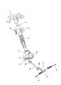
- the rotation of the steering wheel 1 is transmitted to the input shaft 3 of the steering gear unit 2, and the pair of left and right tie rods 4, 4 are pushed and pulled along with the rotation of the input shaft 3.
- the steering angle is given to the front wheels.
- the steering wheel 1 is supported and fixed to the rear end portion of the steering shaft 5.
- the steering shaft 5 is rotatably supported by the steering column 6 while being inserted through the cylindrical steering column 6 in the axial direction.
- a front end portion of the steering column 6 is connected and fixed to a rear end portion of a housing 9 that houses a worm speed reducer 7 and a torque measuring device 8 (see FIG. 21) constituting an electric power steering apparatus.
- An electric motor 10 that is a power source of the electric power steering device is supported and fixed to the housing 9.
- the torque measuring device 8 includes an input shaft 12, an output shaft 13, a displacement measuring device 14 (see FIG. 21) configured to measure a relative displacement amount in the rotational direction of the input shaft 12 and the output shaft 13. Is provided.
- the input shaft 12 and the output shaft 13 are rotatably supported in the housing 9 and are coupled to each other by a torsion bar 11. Since the configuration and operation of such a torque measuring device 8 are conventionally known, detailed description thereof will be omitted.
- the electric motor 10 Based on the measurement result of the torque measuring device 8, the electric motor 10 gives auxiliary torque in the same direction as the operation direction of the steering wheel 1 to the output shaft 13, and the output shaft 13 is input from the steering shaft 5 to the input shaft 12. The motor is rotated with a torque larger than the generated torque.
- the front end portion of the output shaft 13 is connected to the rear end portion of the intermediate shaft 16 via a universal joint 15a, and the front end portion of the intermediate shaft 16 is connected to the input shaft 3 via another universal joint 15b.
- the front-rear direction is the front-rear direction in a state where the electric power steering apparatus is incorporated in a vehicle, and includes a case where the front-rear direction is inclined with respect to the horizontal direction.
- the automobile steering device shown in FIG. 20 incorporates a tilt mechanism configured to adjust the vertical position of the steering wheel 1 and a telescopic mechanism configured to adjust the front-rear position.
- An intermediate portion of the steering column 6 is supported by a support bracket 18 supported by the vehicle body 17 so that the vertical position and the front-back position can be adjusted.
- the support cylinder 19 is provided at the front upper end portion of the housing 9 and is supported by the vehicle body 17 so as to be capable of swinging displacement about the horizontal axis.
- the steering shaft 5 has an inner shaft and an outer shaft which are combined to be able to transmit torque and extend and retract
- the steering column 6 is an outer column and inner column which are combined to expand and contract. And have.
- FIG. 21 shows a structure described in Patent Document 1
- FIG. 22 shows a structure described in Patent Document 2.
- a housing 9 a for housing components other than the electric motor 10 (see FIG. 20) of the electric power steering apparatus is configured by combining the gear housing 20 and the housing cover 21. Yes.
- the output shaft 13 is rotated inside the housing 9 a by a front side rolling bearing 22 held on the inner peripheral surface of the front end portion of the gear housing 20 and a rear side rolling bearing 23 held on the inner peripheral surface of the front end portion of the housing cover 21. It is supported freely.
- the input shaft 12 is rotatably supported inside the housing cover 21 by another rolling bearing 24 (radial needle bearing) held on the inner peripheral surface of the intermediate portion of the housing cover 21.
- a partition plate 25 is fitted in a portion near the rear end inside the gear housing 20a.
- An elastic material 26 is sandwiched between the outer peripheral surface of the partition plate 25 and the inner peripheral surface of the gear housing 20a.
- the output shaft 13a is freely rotatable inside the housing 9b by a front rolling bearing 22a held on the inner peripheral surface of the front end portion of the gear housing 20a and a rear rolling bearing 23a held on the inner peripheral surface of the partition plate 25. It is supported by.
- the input shaft 12a is rotatably supported inside the housing cover 21a by another rolling bearing 24a. Since the structure shown in FIG. 22 does not have a telescopic mechanism, neither the steering shaft 5a nor the steering column 6a is telescopic.
- the housing 9a is configured by combining the gear housing 20 and the housing cover 21, and the output shaft 13 is rotatably supported in the housing 9a by the front and rear rolling bearings 22 and 23. Let Such work is troublesome and reduces the manufacturing efficiency of the electric power steering apparatus.
- An object of the present invention is to provide an electric power steering device that can be easily assembled and can maintain sufficient performance over a long period of time.
- an electric power steering apparatus includes an output shaft, a gear housing, a first rolling bearing and a rolling bearing, a housing cover, and an “intermediate plate”.
- the output shaft rotates to give a steering angle to the wheels.
- the gear housing has a through hole that rotatably supports the output shaft on the inside, and is configured to house a speed reducer for decelerating the rotation of the drive shaft of the electric motor and transmitting it to the output shaft. .
- the first rolling bearing and the second rolling bearing are provided apart from each other in the axial direction of the output shaft in order to rotatably support the output shaft with respect to the gear housing.
- the housing cover is coupled and fixed to the gear housing, and is configured such that an input shaft that is rotationally driven by a steering shaft that is rotationally driven based on an operation of the steering wheel is inserted.
- the first rolling bearing is provided between the inner peripheral surface of the through hole and the outer peripheral surface of the output shaft.
- the second rolling bearing is provided between an inner peripheral surface of an intermediate plate provided in the gear housing and an outer peripheral surface of the output shaft.
- the intermediate plate includes a plurality of large diameter portions and a plurality of small diameter portions, and the large diameter portions and the small diameter portions are alternately provided on the outer peripheral edge portion of the intermediate plate in the circumferential direction.
- the large-diameter portion is press-fitted into the rear portion of the inner peripheral surface of the gear housing with an interference fit so that the intermediate plate is supported and fixed in the gear housing.
- a stepped surface facing backward is provided at the rear of the inner peripheral surface of the gear housing, and the front surface of the outer peripheral edge of the intermediate plate is a stepped surface so that the intermediate plate is positioned relative to the gear housing with respect to the axial direction of the output shaft. You may be faced.
- the front end surface of the housing cover may be abutted against the rear surface of the outer peripheral edge of the intermediate plate.
- a protrusion may be formed in the circumferential direction on the rear surface of the outer peripheral edge of the intermediate plate, and the protrusion may be crushed by the front end surface of the housing cover.
- a plurality of protrusions may be formed along the circumferential direction on the rear surface of the outer peripheral edge of the intermediate plate, and the protrusions may be crushed by the front end surface of the housing cover.
- a step surface facing rearward is provided at the rear part of the inner peripheral surface of the gear housing, and a protrusion is provided on a portion of the front side surface of the intermediate plate facing the step surface, and the protrusion protrudes into the step surface. It may be applied and crushed.
- the front end surface of the housing cover may be abutted against the rear surface of the outer peripheral edge of the intermediate plate.
- the first rolling bearing may be provided in an intermediate portion of the output shaft, and the second rolling bearing may be provided in a portion of the output shaft closer to the rear end of the output shaft than the intermediate portion.
- the intermediate plate may be made by injection molding of a thermoplastic resin containing a thermosetting resin or glass fiber.
- One of the two rolling bearings that rotatably support the output shaft with respect to the gear housing is provided between the inner peripheral surface of the intermediate plate and the outer peripheral surface of the output shaft. Since the intermediate plate is assembled in a state in which the rolling bearing can be seen before the housing cover is assembled, the assembly work of the electric power steering apparatus can be facilitated.
- the large-diameter portion and small-diameter portion of the intermediate plate are alternately provided on the outer peripheral edge of the intermediate plate with respect to the circumferential direction, and the large-diameter portion is press-fitted into the rear portion of the inner peripheral surface of the gear housing. It can be done. That is, the intermediate plate can be press-fitted into the rear part of the gear housing without restricting the difference (tightening allowance) in the free state between the inner diameter of the rear part of the gear housing and the outer diameter of the intermediate plate. Can be held firmly (can improve robustness).
- the intermediate plate is press-fitted and fixed to the rear inner peripheral surface of the gear housing with an interference fit.
- the performance of the electric power steering apparatus can be maintained over a long period of time. That is, since the intermediate plate is press-fitted and fixed to the gear housing, the posture of the rolling bearing held on the inner peripheral surface of the intermediate plate does not change after use for a long period of time. For this reason, the attitude of the output shaft that is rotatably supported by the rolling bearing does not change, and the meshing state of the speed reducer does not become poor, and the measurement accuracy of the torque measuring device does not deteriorate.
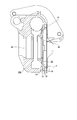
- FIG. 1 is a partial cross-sectional view of an electric power steering apparatus according to a first embodiment of the present invention.
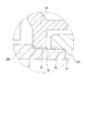
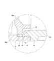
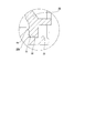
- the enlarged view of the X section of FIG. The rear view which abbreviate
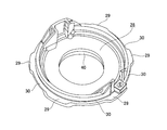
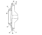
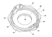
- the gear housing is a front perspective view.
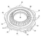
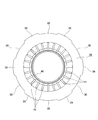
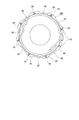
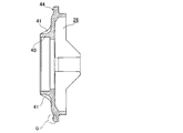
- middle plate which concerns on 4th Embodiment of this invention.
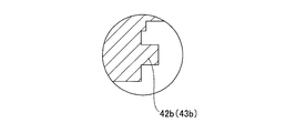
- the partial expanded sectional view which shows the other example of the cross-sectional shape of a rear protrusion or a rear protrusion.
- the partial expanded sectional view which shows the further another example of the cross-sectional shape of a rear protrusion or a rear protrusion.
- Sectional drawing of the one part of the electrically driven power steering apparatus which concerns on 5th Embodiment of this invention The enlarged view of the P section of FIG.
- the partial expanded sectional view which shows the other example of the cross-sectional shape of a front side protrusion.
- the partial expanded sectional view which shows the further another example of the cross-sectional shape of a front side protrusion.
- the partial expanded sectional view which shows the further another example of the cross-sectional shape of a front side protrusion.
- the partial cutting side view which shows an example of an electric power steering device. 1 is a cross-sectional view of a part of an electric power steering device according to a first conventional technique. Sectional drawing of a part of electric power steering device concerning the 2nd prior art.
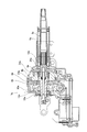
- the electric power steering apparatus includes an input shaft 12b, an output shaft 13b, and a housing 9 that rotatably supports the input shaft 12b and the output shaft 13b.
- the housing 9 is configured by combining a gear housing 20b and a housing cover 21b.
- Each of the gear housing 20b and the housing cover 21b is formed by, for example, die casting using an aluminum alloy or injection molding using a high-functional resin.
- the input shaft 12b and the output shaft 13b are formed in a hollow circular tube, and are connected by the torsion bar 11 in a state of being arranged concentrically with each other.
- the output shaft 13b is connected to the input shaft 3 (see FIG. 20) of the steering gear unit 2 through the universal joints 15a and 15b and the intermediate shaft 16, and the input shaft 3 is rotated by a predetermined amount in a predetermined direction so that A predetermined rudder angle is provided.
- the input shaft 12b can be driven to rotate by the steering shaft 5.
- the input shaft 12b and the output shaft 13b elastically deform the torsion bar 11 in the twisting direction by the steering torque applied to the input shaft 12b and the resistance against the rotation of the output shaft 13b.
- This relative displacement amount can be measured by a torque measuring device 8b provided between the outer peripheral surface of the intermediate portion of the input shaft 12b and the outer peripheral surface of the rear end portion of the output shaft 13b.
- the measurement signal of the torque measuring device 8b is sent to a controller for controlling the energization to the electric motor 10 (see FIG. 20), and the controller controls the energizing direction and the energizing amount to the electric motor 10, and the worm deceleration.
- the auxiliary steering force of the output shaft 13b is applied through the machine 7a.
- a radial needle bearing 27 is provided between the outer peripheral surface of the front end portion of the input shaft 12b and the rear end portion of the inner peripheral surface of the output shaft 13b to ensure the concentricity of both the shafts 12b and 13b.
- An intermediate plate 28 made in the same manner as the gear housing 20b and the housing cover 21b is press-fitted and fixed in the housing 9c by an interference fit.
- the intermediate plate 28 is used to support a portion near the rear end of the intermediate portion of the output shaft 13b.
- the intermediate plate 28 has a plurality of large diameter portions 29 and a plurality of small diameter portions 30.
- the large diameter portion 29 and the small diameter portion 30 are alternately provided on the outer peripheral edge portion of the intermediate plate 28 in the circumferential direction. In the illustrated example, six large diameter portions 29 and six small diameter portions 30 are provided.
- Each large-diameter portion 29 is supported and fixed in the gear housing 20b by press-fitting into the inner peripheral surface of the rear portion of the gear housing 20b with an interference fit.
- a stepped surface 31 facing rearward is provided at a portion near the rear end opening of the inner peripheral surface of the gear housing 20b.
- the rear side portion of the inner peripheral surface of the gear housing 20b from the step surface 31 is continuously connected by the small step portion with the small-diameter cylindrical surface portion 32 near the step surface 31 and the large-diameter cylindrical surface portion 33 far from the step surface 31 on the opening side.
- a stepped cylindrical surface is used.
- the outer diameter in the free state of each large diameter portion 29 at the outer peripheral edge of the intermediate plate 28 is slightly larger than the inner diameter in the free state of the small diameter cylindrical surface portion 32.
- the inner diameter of the large-diameter cylindrical surface portion 33 in the free state is slightly larger than the outer diameter of each large-diameter portion 29 in the free state.
- the intermediate plate 28 is press-fitted into the small-diameter cylindrical surface portion 32 at the large-diameter portion 29, and the front surface of the outer peripheral edge of the intermediate plate 28 is abutted against the stepped surface 31 to press-fit and fix the intermediate plate 28 at a predetermined position in the housing 9c is doing.
- the rear end opening of the gear housing 20b is closed by the housing cover 21b.
- Coupling flanges 34a and 34b are provided at portions where the outer peripheral surface of the gear housing 20b and the outer peripheral surface of the housing cover 21b are engaged with each other at two positions opposite to each other in the diameter direction.
- the intermediate plate 28 is press-fitted and fixed in the gear housing 20b, and the front end portion of the housing cover 21b is fitted into the large-diameter cylindrical surface portion 33 of the rear end opening of the gear housing 20b without rattling.
- the front side surface of the flange portion 35 formed on the end surface near the front end of the outer peripheral surface of the housing cover 21b is abutted against the end surface.
- the output shaft 13b is assembled to each other in this manner, and is rotatably supported by front and rear rolling bearings 22b and 23b in a gear housing 20b in which an intermediate plate 28 is press-fitted and fixed.
- the outer ring of the front rolling bearing 22b is placed on the inner side of the through hole 36 formed in the center portion of the gear housing 20b along the front-rear direction and having a stepped surface facing the rear in the middle portion of the inner peripheral surface. And is retained by a radially outer retaining ring 37.
- the inner ring of the front rolling bearing 22b is externally fitted to the output shaft 13b together with the worm wheel 38 of the worm reduction gear 7a from the front, and the rear inner peripheral edge of the worm wheel 38 is formed on the outer peripheral surface of the output shaft 13b. While abutting against the stepped surface that faces, it is prevented from coming off by a radially inner retaining ring 39.
- the outer ring of the rear side rolling bearing 23b is internally fitted and fixed to the cylindrical portion 40 formed at the center of the intermediate plate 28 by an interference fit.
- a plurality of reinforcing ribs 41 arranged in the circumferential direction are formed between the outer peripheral surface of the cylindrical portion 40 and the front side surface of the intermediate plate 28, and the rigidity of the cylindrical portion 40, and thus the rear rolling bearing 23 b. Support rigidity is ensured.
- Each of the reinforcing ribs 41 extends in the radial direction and protrudes in the axial direction.
- the inner ring of the rear rolling bearing 23b is externally fixed to the large-diameter portion formed near the rear end of the intermediate portion of the output shaft 13b and having a larger outer diameter than both the front and rear side portions by an interference fit.
- the rear surface of the inner peripheral edge of the worm wheel 38 is abutted against the stepped surface that continues from the front edge of the large diameter portion.
- the position of the cylindrical portion 40 of the intermediate plate 28 and the position of the outer peripheral edge of the intermediate plate 28 are shifted in the axial direction.
- the inner ring of the rear side rolling bearing 23b may be fitted on the output shaft 13b by gap fitting. This gap fitting absorbs thermal deformation in the axial direction of the intermediate plate 28. That is, the rear side rolling bearing 23 b is not affected by the axial thermal deformation of the intermediate plate 28. Therefore, the performance of the electric power steering apparatus is not affected by the axial thermal deformation of the intermediate plate 28.
- the front rolling bearing 22b is held inside the through hole 36 of the gear housing 20b. deep. In this state, the radially outer retaining ring 37 is also attached. Since this operation is performed before other members are assembled in the gear housing 20b, it can be easily performed.
- the worm wheel 38, the rear rolling bearing 23b, and the intermediate plate 28 are attached to the portion near the rear end of the outer peripheral surface of the output shaft 13b.
- the input shaft 12b is also coupled to the output shaft 13b via the torsion bar 11, and the torque measuring device 8b is also assembled. Further, the input shaft 12b and the steering shaft 5 are coupled as necessary. Since these operations are also performed before the output shaft 13b is assembled in the gear housing 20b, it can be easily performed.
- the housing cover 21b is loosely fitted to the steering shaft 5 in advance as required, and is moved rearward so as not to hinder the assembly work of other members.
- the output shaft 13b is inserted into the inner ring of the front rolling bearing 22b from the rear to the front. Then, the rear end surface of the inner ring is brought into contact with the front end surface of the radially inner end portion of the worm wheel 38.
- Each large-diameter portion 29 and small-diameter cylindrical surface portion 32 are fitted in only a part of the circumferential direction (in the illustrated example, a range less than 1 ⁇ 2 of the entire circumference), so that the intermediate plate 28 to the small-diameter cylindrical surface portion 32 is fitted. Can be easily press-fitted.
- the intermediate plate 28 can be easily press-fitted into the small-diameter cylindrical surface portion 32 without particularly restricting the tightening allowance that is the difference between the inner diameter of the small-diameter cylindrical surface portion 32 and the outer diameter of each large-diameter portion 29.
- the support strength of the intermediate plate 28 with respect to the gear housing 20b can be sufficiently secured.
- the output shaft 13b projects sufficiently forward from the inner ring of the front rolling bearing 22b.
- a radially inner retaining ring 39 is attached.
- the housing cover 21b is moved forward so that the front end portion of the housing cover 21b is fitted into the large-diameter cylindrical surface portion 33 on the inner peripheral surface of the rear end portion of the gear housing 20b, and the front side surface of the flange portion 35 is fitted to the gear housing 20b. It hits the rear end face.
- each coupling flange 34a, 34b is adjusted, and each coupling flange 34a, 34b is bolted with a bolt and a nut, or a bolt inserted through a through hole formed in one coupling flange 34b, 34b,
- the other coupling flanges 34a, 34a are coupled and fixed by being screwed into screw holes formed therein and further tightened. Since a series of these operations can be performed with visual confirmation, it is easy.
- the worm wheel 38 and the worm constituting the worm speed reducer 7a mesh with each other while rotating the worm when the electric motor 10 is assembled to the gear housing 20b. This is the same as the conventional structure.
- the intermediate plate 28 is firmly supported and fixed inside the housing 9c including the gear housing 20b and the housing cover 21b. Accordingly, the posture of the rear rolling bearing 23b held on the inner peripheral surface of the cylindrical portion 40 of the intermediate plate 28 does not change even after use for a long period of time. For this reason, even if it is used over a long period of time, the posture of the output shaft 13b that is rotatably supported by the rear side rolling bearing 23b and the front side rolling bearing 22b does not change. As a result, the meshing state of the worm speed reducer 7a does not become defective, and the measurement accuracy of the torque measuring device 8b does not deteriorate.
- the intermediate plate 28 can be made by injection molding of synthetic resin.
- synthetic resin that can be preferably used include a thermosetting resin or a thermoplastic resin containing about 20 to 60% by volume of reinforcing fibers.
- this resin is made of a resin composition that can be used continuously even in a temperature environment of ⁇ 40 ° C. to 85 ° C., which is the operating environment temperature in the column portion of the electric power steering device, and can be used continuously.
- the linear expansion coefficient is 1.2 ⁇ 10 ⁇ 5 in both the fiber direction and the fiber perpendicular direction in the temperature range of 23 ° C. to 80 ° C. It is preferably in the range of 5.5 ⁇ 10 ⁇ 5 (1 / ° C.), and the water absorption when left in water at 23 ° C. for 24 hours is preferably 4% or less.
- the resin portion when exposed to a high temperature and high humidity environment for a long time during transportation or the like, the resin portion may be damaged due to a decrease in mechanical properties due to moisture absorption deterioration of the intermediate plate formed of resin. Therefore, the resin preferably has a tensile strength retention of 70% or more after being left in an environment of 85 ° C. and 85% RH for 500 hours.
- the resin composition that can be continuously used in a temperature environment of ⁇ 40 ° C. to 85 ° C. is not particularly limited, but includes polyethylene terephthalate (PET), polybutylene terephthalate (PBT), polyamide (PA) 6, polyamide 11, So-called engineering plastics such as polyamide 12, polyamide 66, polyamide 610, polyamide 612, polyamide 46, polyamide 410, modified polyamide 6T, polyamide 9T, fluororesin, polyphenylene sulfide (PPS), polyethersulfone (PES), polyetherimide (PEI), polyamideimide (PAI), thermoplastic polyimide, polyetheretherketone (PEEK), so-called super engineering plastics such as polyethernitrile (PEN) Can be exemplified fat, it may be used alone or in combination.
- PPS polyethersulfide
- PES polyethersulfone
- PAI polyetherimide
- PEEK polyetheretherketone
- super engineering plastics such as
- polyethylene terephthalate (PET), polyamide 66, polyamide 46, and polyphenylene sulfide have a good balance between cost and performance, and can be suitably used.
- thermosetting resins such as phenol resins, urea resins, unsaturated polyester resins, and polyurethane resins can be suitably used for applications requiring heat resistance and dimensional stability.
- the linear expansion coefficient should be in the range of 1.2 ⁇ 10 ⁇ 5 to 5.5 ⁇ 10 ⁇ 5 (1 / ° C.) in the fiber direction and in the direction perpendicular to the fiber in the temperature range of 23 ° C. to 80 ° C. Is preferred.
- the linear expansion coefficient is smaller than 1.2 ⁇ 10 ⁇ 5 (1 / ° C.)
- the linear expansion coefficient of the rear side rolling bearing 23 press-fitted radially inward of the intermediate plate 28 is 1.2 ⁇ 10 ⁇ 5 (1 Therefore, there is a difference between the linear expansion coefficient of the intermediate plate 28 and the linear expansion coefficient of the rear side rolling bearing 23, and a gap is formed between the cylindrical portion 40 and the outer diameter surface of the rear side rolling bearing 23.
- the fibrous filler is not particularly limited, and examples thereof include glass fiber, carbon fiber, metal fiber, aramid fiber, aromatic polyimide fiber, liquid crystal polyester fiber, silicon carbide fiber, alumina fiber, and boron fiber. It can. Among these, glass fiber and carbon fiber are preferable because of their good reinforcement. As the glass fiber, an insulating glass fiber that has little influence on the electromagnetic induction of the torque measuring device 8 is more preferable.
- the content of the fibrous filler in the total composition is preferably 30 to 55% by mass, more preferably 35 to 55% by mass. Even if the fibrous filler exceeds 55% by mass, not only the melt fluidity of the resin composition is remarkably lowered and the moldability is deteriorated, but further improvement in mechanical properties and dimensional stability is expected. On the other hand, since the deformability of the material becomes extremely small, the intermediate plate 28 may be damaged when the intermediate plate 28 is molded or assembled. Conversely, if the content of the fibrous filler in the entire composition is less than 30% by mass, the reinforcing effect of mechanical properties is small, and the dimensional stability is insufficient.
- the dimensional stability means that the linear expansion coefficient is 1.2 ⁇ 10 ⁇ 5 to 5.5 ⁇ 10 ⁇ 5 (1 / ° C), which means that the water absorption when left in water at 23 ° C for 24 hours is in the range of 4% or less.
- the resin forming the intermediate plate 28 is made of a silane-based fibrous filler so as to improve the adhesion and dispersibility between the resin and the fibrous filler by giving affinity between the resin and the fibrous filler.
- a silane-based fibrous filler so as to improve the adhesion and dispersibility between the resin and the fibrous filler by giving affinity between the resin and the fibrous filler.
- it can treat with coupling agents, such as a coupling agent and a titanate coupling agent, and the surface treatment agent according to the other objective, it is not limited to these.
- additives may be added within the range not impairing the object of the present invention, such as graphite, hexagonal boron nitride, fluorine mica, tetrafluoroethylene resin powder, tungsten disulfide, molybdenum disulfide, etc.
- a functional epoxy compound, a piperidine derivative, a piperazinone derivative, or the like can be preferably used.
- the hydrolysis inhibitor may be added in an amount of 0.01 to 5% by mass, preferably 0.05 to 2% by mass, based on the polyester resin.
- the temperature at the time of melt impregnation is not particularly limited, but may be appropriately selected within a temperature range in which the melting of the resin as the base material sufficiently proceeds and does not deteriorate.
- the method for manufacturing the intermediate plate 28 is not particularly limited.
- the intermediate plate 28 can be formed by an ordinary method such as injection molding, compression molding, transfer molding, or the like.
- the injection molding method is preferable because it is excellent in productivity and can provide an inexpensive intermediate plate 28.
- the intermediate plate 28 can also be made by die casting of a light alloy such as an aluminum alloy.
- FIG. 9 shows a second embodiment of the present invention.
- the front end surface of the housing cover 21 c is abutted against the outer peripheral edge of the rear surface of the intermediate plate 28. Therefore, in the case of this example, the fixing force of the intermediate plate 28 with respect to the housing 9d is based on press fitting, the outer peripheral surface of each large diameter portion 29 (see FIGS. 3 and 8) formed on the outer peripheral edge of the intermediate plate 28, and the gear. This is the sum of the frictional force acting between the small diameter cylindrical surface portion 32 of the housing 20b and the clamping force caused by the step surface 31 of the gear housing 20b and the front end surface of the housing cover 21c. Therefore, the fixing strength of the intermediate plate 28 with respect to the housing 9d becomes higher. Since the configuration and operation of the other parts are the same as those of the first embodiment described above, the same parts are denoted by the same reference numerals, and redundant description is omitted.
- a rear ridge 42 is formed over the entire circumference with a triangular cross-sectional shape that decreases in width in the radial direction toward the tip.
- the rear protrusion 42 is formed in the process of screwing and tightening a bolt and a nut (or screw hole) in order to couple and fix the gear housing 20b and the housing cover 21b. It is crushed. For this reason, it is possible to prevent the bolt from loosening while keeping the force required for tightening the bolt low (reducing the loss of axial force). Since the configuration and operation of the other parts are the same as those of the second embodiment described above, the illustration and description regarding the equivalent parts are omitted.
- FIG. 12 shows a fourth embodiment of the present invention.
- rear projections 43, 43 each having a triangular pyramid shape are formed at a plurality of circumferentially equidistant positions on the outer peripheral edge of the rear surface of the intermediate plate 28b. Then, in the process of coupling and fixing the gear housing 20b and the housing cover 21b (see FIG. 10), the front end surface of the housing cover 21b is squeezed while the rear projections 43 and 43 are crushed by the front end surface of the housing cover 21b. It abuts on the outer peripheral edge of the rear surface 28b.
- the rear protrusions 43 and 43 are formed in the process of screwing and further tightening bolts and nuts (or screw holes) in order to couple and fix the gear housing 20b and the housing cover 21b. Is crushed. For this reason, as in the case of the third embodiment described above, it is possible to prevent the bolt from loosening while keeping the force required for tightening the bolt low. Since the configuration and operation of the other parts are the same as those of the second embodiment described above, the illustration and description regarding the equivalent parts are omitted.
- the cross-sectional shape of the rear protrusion 42 or the rear protrusion 43 is not limited to a triangle. If the shape is crushed by an appropriate amount by tightening the bolt, the cross-sectional shape as shown in FIG. 13A is the trapezoidal rear protrusion 42a (or the truncated conical rear protrusion 43a), and the cross-section as shown in FIG. 13B.
- the shape of the rear protrusion 42b (or columnar rear protrusion 43b) is quadrangular, and the shape of the cross section as shown in FIG. 13C is the semicircular rear protrusion 42c (or hemispherical rear protrusion 43c). You can also do things.
- an intermediate plate 28 made in the same manner as the gear housing 20b and the housing cover 21b is press-fitted and fixed in the housing 9c by an interference fit.
- the intermediate plate 28 is used to support a portion near the rear end of the intermediate portion of the output shaft 13b.
- the intermediate plate 28 is formed by alternately providing a plurality of large-diameter portions 29 and small-diameter portions 30 (6 in the illustrated example) on the outer peripheral edge portion in the circumferential direction. Each large-diameter portion 29 is supported and fixed in the gear housing 20b by press-fitting into the rear inner peripheral surface of the gear housing 20b with an interference fit.
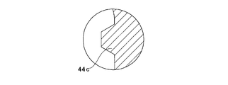
- a front protrusion that has a triangular cross-sectional shape at a portion closer to the outer diameter of the front surface of the intermediate plate 28 (portion closer to the inner diameter than the periphery of each small diameter portion 30), and the width in the radial direction becomes narrower toward the tip edge. 44 is formed over the entire circumference.
- a stepped surface facing rearward at a portion near the rear end opening of the inner peripheral surface of the gear housing 20b. 31 is provided.
- the rear side portion of the inner peripheral surface of the gear housing 20b from the step surface 31 is continuously connected by the small step portion with the small-diameter cylindrical surface portion 32 near the step surface 31 and the large-diameter cylindrical surface portion 33 far from the step surface 31 on the opening side.
- a stepped cylindrical surface is used.
- the outer diameter in the free state of each large diameter portion 29 at the outer peripheral edge of the intermediate plate 28 is slightly larger than the inner diameter in the free state of the small diameter cylindrical surface portion 32.
- the inner diameter of the large-diameter cylindrical surface portion 33 in the free state is slightly larger than the outer diameter of each large-diameter portion 29 in the free state. Then, the intermediate plate 28 is press-fitted into the small-diameter cylindrical surface portion 32 at each of the large-diameter portions 29, and the front protrusion 44 formed on the front surface of the intermediate plate 28 is abutted against the step surface 31, so that the intermediate plate 28 is attached to the housing 9c. It is press-fitted and fixed at a predetermined position. In this state, the front end of the front protrusion 44 is crushed by the step surface 31. Then, a portion between the step surface 31 and the front side surface of the intermediate plate 28 is sealed.
- the rear end opening of the gear housing 20b is closed by the housing cover 21b.
- Coupling flanges 34a and 34b are provided at portions where the outer peripheral surface of the gear housing 20b and the outer peripheral surface of the housing cover 21b are engaged with each other at two positions opposite to each other in the diameter direction.
- the front end portion of the housing cover 21b is fitted into the large-diameter cylindrical surface portion 33 of the rear end opening of the gear housing 20b without rattling, and further, on the rear end surface of the gear housing 20b, near the front end portion of the outer peripheral surface of the housing cover 21b.
- the front side of the formed collar part 35 is abutted. From this state, bolts and nuts (not shown) inserted through the through holes formed in the respective coupling flanges 34a and 34b are screwed and further tightened, and the gear housing 20b and the housing cover 21b are coupled and fixed to fix the housing 9c. Constitute.
- the large-diameter portion 29 formed on the outer peripheral edge of the intermediate plate 28 is press-fitted into the small-diameter cylindrical surface portion 32 of the gear housing 20b, while the output shaft 13b is
- the inner ring of the front rolling bearing 22b is inserted from the rear to the front, and the rear end surface of the inner ring and the front end surface of the radially inner end of the worm wheel 38 are abutted against each other.
- Each large-diameter portion 29 and small-diameter cylindrical surface portion 32 are fitted in only a part of the circumferential direction (in the illustrated example, a range less than 1 ⁇ 2 of the entire circumference), so that the intermediate plate 28 to the small-diameter cylindrical surface portion 32 is fitted.
- the intermediate plate 28 can be easily press-fitted into the small-diameter cylindrical surface portion 32 without particularly restricting the tightening allowance that is the difference between the inner diameter of the small-diameter cylindrical surface portion 32 and the outer diameter of each large-diameter portion 29.
- the support strength of the intermediate plate 28 with respect to the gear housing 20b can be sufficiently secured.
- the lubricant in the portion where the worm reduction gear 7a is installed is installed in the installation space of the torque measuring device 8b without providing a separate sealing material. Since leakage to the side can be prevented, a structure capable of preventing malfunction of the worm speed reducer 7a and the torque measuring device 8b can be configured at low cost.
- the cross-sectional shape of the front protrusion 44 is not limited to a triangle. If the shape is crushed by an appropriate amount by tightening the bolt, the cross-sectional shape as shown in FIG. 19A is a trapezoidal front ridge 44a, and the cross-sectional shape as shown in FIG. 19B is a square front ridge 44b.
- the cross-sectional shape as shown in (2) can be a semicircular front protrusion 44c. Since the configuration and operation of the other parts are the same as those in the first embodiment described above, illustration and explanation regarding the equivalent parts are omitted.
Abstract
Description
そこで、樹脂は、85℃、85%RHの環境下に500時間放置した後の引張強度保持率が70%以上であることが好ましい。 In addition, when exposed to a high temperature and high humidity environment for a long time during transportation or the like, the resin portion may be damaged due to a decrease in mechanical properties due to moisture absorption deterioration of the intermediate plate formed of resin.
Therefore, the resin preferably has a tensile strength retention of 70% or more after being left in an environment of 85 ° C. and 85% RH for 500 hours.
5、5a ステアリングシャフト
7、7a ウォーム減速機
10 電動モータ
12、12a、12b 入力軸
13、13a、13b 出力軸
17 車体
20、20a、20b ギヤハウジング
21、21a、21b、21c ハウジングカバー
22、22a、22b 第1転がり軸受
23、23a、23b 第2転がり軸受
28、28a、28b 中間プレート
29 大径部
30 小径部
31 段差面
36 貫通孔
38 ウォームホイール
42、42a、42b、42c 後側突条
43、43a、43b、43c 後側突起
44、44a、44b、44c 前側突条 DESCRIPTION OF
Claims (9)
- 回転して車輪に舵角を付与する出力軸と、
内側に前記出力軸を回転自在に支持する貫通孔を有し、電動モータの駆動軸の回転を減速して前記出力軸に伝達する為の減速機が収納されるように構成されたギヤハウジングと、
前記ギヤハウジングに対して前記出力軸を回転自在に支持する為、前記出力軸の軸方向に離隔して設けられた第1転がり軸受と第2転がり軸受と、
前記ギヤハウジングに結合固定され、ステアリングホイールの操作に基づいて回転駆動されるステアリングシャフトにより回転駆動される入力軸が挿通されるように構成されたハウジングカバーと、
前記ギヤハウジング内に設けられた中間プレートと、を備えた電動式パワーステアリング装置であって、
前記第1転がり軸受は、前記貫通孔の内周面と前記出力軸の外周面との間に設けられ、
前記第2転がり軸受は、中間プレートの内周面と、前記出力軸の外周面との間に設けられ、
前記中間プレートは、複数の大径部と複数の小径部とを備え、大径部と小径部は、中間プレートの外周縁部に円周方向に関して交互に設けられ、
前記中間プレートがギヤハウジング内に支持固定されるように、前記大径部が前記ギヤハウジングの内周面の後部に締り嵌めで圧入されている、電動式パワーステアリング装置。 An output shaft that rotates and imparts a steering angle to the wheels;
A gear housing having a through hole for rotatably supporting the output shaft on the inside, and configured to house a speed reducer for decelerating and transmitting the rotation of the drive shaft of the electric motor to the output shaft; ,
A first rolling bearing and a second rolling bearing provided to be spaced apart in the axial direction of the output shaft in order to rotatably support the output shaft with respect to the gear housing;
A housing cover that is coupled and fixed to the gear housing, and is configured to pass through an input shaft that is rotationally driven by a steering shaft that is rotationally driven based on an operation of a steering wheel;
An electric power steering device comprising an intermediate plate provided in the gear housing,
The first rolling bearing is provided between an inner peripheral surface of the through hole and an outer peripheral surface of the output shaft,
The second rolling bearing is provided between an inner peripheral surface of the intermediate plate and an outer peripheral surface of the output shaft,
The intermediate plate includes a plurality of large-diameter portions and a plurality of small-diameter portions, and the large-diameter portions and the small-diameter portions are alternately provided in the circumferential direction on the outer peripheral edge portion of the intermediate plate,
The electric power steering apparatus, wherein the large-diameter portion is press-fitted into the rear portion of the inner peripheral surface of the gear housing with an interference fit so that the intermediate plate is supported and fixed in the gear housing. - 前記ギヤハウジングの内周面の後部に、後方を向いた段差面が設けてられ、
前記中間プレートが前記ギヤハウジングに対して前記出力軸の軸方向に関して位置決めされるように、前記中間プレートの外周縁部の前面が段差面に突き当てられている、請求項1に記載した電動式パワーステアリング装置。 On the rear part of the inner peripheral surface of the gear housing, a step surface facing backward is provided,
The electric type according to claim 1, wherein a front surface of an outer peripheral edge portion of the intermediate plate is abutted against a step surface so that the intermediate plate is positioned with respect to the gear housing with respect to an axial direction of the output shaft. Power steering device. - 前記中間プレートの外周縁部の後面に前記ハウジングカバーの前端面が突き当てられている、請求項2に記載した電動式パワーステアリング装置。 The electric power steering apparatus according to claim 2, wherein a front end surface of the housing cover is abutted against a rear surface of an outer peripheral edge portion of the intermediate plate.
- 前記中間プレートの外周縁部の後面には、突条が周方向に形成され、
前記突条は、前記ハウジングカバーの前端面により押し潰されている、請求項3に記載した電動式パワーステアリング装置。 On the rear surface of the outer peripheral edge of the intermediate plate, a protrusion is formed in the circumferential direction,
The electric power steering apparatus according to claim 3, wherein the protrusion is crushed by a front end surface of the housing cover. - 前記中間プレートの外周縁部の後面には、複数の突起が周方向に形成され、
前記突起は、前記ハウジングカバーの前端面により押し潰されている、請求項3に記載した電動式パワーステアリング装置。 A plurality of protrusions are formed in the circumferential direction on the rear surface of the outer peripheral edge of the intermediate plate,
The electric power steering apparatus according to claim 3, wherein the protrusion is crushed by a front end surface of the housing cover. - 前記ギヤハウジングの内周面の後部に、後方を向いた段差面が設けられ、
前記中間プレートの前側面の、前記段差面に対向する部分に、突条が設けられ、
前記突条は、前記段差面に突き当てられて押し潰されている、請求項1に記載した電動式パワーステアリング装置。 On the rear part of the inner peripheral surface of the gear housing, a step surface facing backward is provided,
On the front side surface of the intermediate plate, a protrusion is provided on a portion facing the step surface,
The electric power steering apparatus according to claim 1, wherein the protrusion is pressed against the stepped surface and crushed. - 前記中間プレートの外周縁部の後面には、前記ハウジングカバーの前端面が突き当てられている、請求項6に記載した電動式パワーステアリング装置。 The electric power steering apparatus according to claim 6, wherein a front end surface of the housing cover is abutted against a rear surface of an outer peripheral edge portion of the intermediate plate.
- 前記第1転がり軸受は、前記出力軸の中間部に設けられ、
前記第2転がり軸受は、前記中間部よりも前記出力軸の後端寄りの出力軸の部分に設けられている、請求項1に記載した電動式パワーステアリング装置。 The first rolling bearing is provided at an intermediate portion of the output shaft,
2. The electric power steering apparatus according to claim 1, wherein the second rolling bearing is provided in a portion of the output shaft closer to a rear end of the output shaft than the intermediate portion. - 前記中間プレートは、熱硬化性樹脂又はガラス繊維を含有する熱可塑性樹脂の射出成形により造られている、請求項1~8のうちの何れか1項に記載した電動式パワーステアリング装置。 The electric power steering apparatus according to any one of claims 1 to 8, wherein the intermediate plate is made by injection molding of a thermosetting resin or a thermoplastic resin containing glass fibers.
Priority Applications (4)
| Application Number | Priority Date | Filing Date | Title |
|---|---|---|---|
| CN201380001894.XA CN103906670B (en) | 2012-10-29 | 2013-10-28 | Electric type power steering device |
| JP2013556697A JP6024672B2 (en) | 2012-10-29 | 2013-10-28 | Electric power steering device |
| EP13851138.1A EP2913246B1 (en) | 2012-10-29 | 2013-10-28 | Electric power-steering device |
| US14/388,024 US9233709B2 (en) | 2012-10-29 | 2013-10-28 | Electric power steering apparatus |
Applications Claiming Priority (4)
| Application Number | Priority Date | Filing Date | Title |
|---|---|---|---|
| JP2012237788 | 2012-10-29 | ||
| JP2012237789 | 2012-10-29 | ||
| JP2012-237788 | 2012-10-29 | ||
| JP2012-237789 | 2012-10-29 |
Publications (1)
| Publication Number | Publication Date |
|---|---|
| WO2014069423A1 true WO2014069423A1 (en) | 2014-05-08 |
Family
ID=50627328
Family Applications (1)
| Application Number | Title | Priority Date | Filing Date |
|---|---|---|---|
| PCT/JP2013/079178 WO2014069423A1 (en) | 2012-10-29 | 2013-10-28 | Electric power-steering device |
Country Status (5)
| Country | Link |
|---|---|
| US (1) | US9233709B2 (en) |
| EP (1) | EP2913246B1 (en) |
| JP (1) | JP6024672B2 (en) |
| CN (1) | CN103906670B (en) |
| WO (1) | WO2014069423A1 (en) |
Cited By (4)
| Publication number | Priority date | Publication date | Assignee | Title |
|---|---|---|---|---|
| WO2017169523A1 (en) * | 2016-03-29 | 2017-10-05 | サンデン・オートモーティブコンポーネント株式会社 | Case-sealing structure and compressor provided with same |
| WO2022269900A1 (en) * | 2021-06-25 | 2022-12-29 | 株式会社ジェイテクト | Steering device |
| WO2022269899A1 (en) * | 2021-06-25 | 2022-12-29 | 株式会社ジェイテクト | Steering device |
| WO2023170957A1 (en) * | 2022-03-11 | 2023-09-14 | 株式会社ジェイテクト | Steering device |
Families Citing this family (7)
| Publication number | Priority date | Publication date | Assignee | Title |
|---|---|---|---|---|
| JP6198763B2 (en) | 2015-03-10 | 2017-09-20 | 株式会社ショーワ | Housing structure and power steering device |
| US10845257B2 (en) * | 2015-11-03 | 2020-11-24 | Basf Se | Device and method for sensing torques, torsional natural frequencies, and/or torsional oscillations without contact |
| JP6616670B2 (en) * | 2015-11-18 | 2019-12-04 | Kyb株式会社 | Power steering apparatus and steering apparatus including the same |
| KR101916689B1 (en) * | 2016-10-19 | 2018-11-09 | 고학석 | Drying system for coating device using air knife coating |
| US11001294B2 (en) * | 2017-08-23 | 2021-05-11 | Steering Solutions Ip Holding Corporation | Steering column power assist assembly housing |
| CN111683859B (en) * | 2018-01-15 | 2022-07-29 | 日本精工株式会社 | Gear housing for electric power steering device |
| JP7043972B2 (en) | 2018-05-23 | 2022-03-30 | マツダ株式会社 | Vehicle body structure |
Citations (9)
| Publication number | Priority date | Publication date | Assignee | Title |
|---|---|---|---|---|
| JPH1035525A (en) * | 1996-07-24 | 1998-02-10 | Kayaba Ind Co Ltd | Power steering device |
| JP2001138930A (en) * | 1999-11-16 | 2001-05-22 | Aisin Seiki Co Ltd | Steering wheel steering device |
| JP2002518242A (en) | 1998-06-16 | 2002-06-25 | ティーアールダブリュー・ルーカス・ヴァリティ・エレクトリック・ステアリング・リミテッド | Improvements on power assisted steering |
| JP2003172332A (en) * | 2001-12-06 | 2003-06-20 | Toyo Hatsujo Kogyo Kk | Washer |
| JP2006256499A (en) * | 2005-03-17 | 2006-09-28 | Showa Corp | Steering device |
| JP2007223501A (en) * | 2006-02-24 | 2007-09-06 | Nsk Ltd | Electric power steering device |
| JP2008213674A (en) * | 2007-03-05 | 2008-09-18 | Jtekt Corp | Electric power steering device and assembling method for electric power steering device |
| JP2009298246A (en) | 2008-06-11 | 2009-12-24 | Jtekt Corp | Electric power steering device |
| JP2010247790A (en) * | 2009-04-20 | 2010-11-04 | Jtekt Corp | Electric power steering device |
Family Cites Families (12)
| Publication number | Priority date | Publication date | Assignee | Title |
|---|---|---|---|---|
| JPS59107560U (en) * | 1983-01-07 | 1984-07-19 | 株式会社東芝 | Bearing bracket for vertical rotating electric machine |
| DE60310782T2 (en) * | 2002-02-04 | 2007-10-11 | Jtekt Corp., Osaka | Electric power steering |
| JP4671605B2 (en) * | 2004-01-13 | 2011-04-20 | 株式会社ジェイテクト | Torque detection device |
| JP4389616B2 (en) * | 2004-03-15 | 2009-12-24 | 日本精工株式会社 | Electric power steering device |
| WO2006080529A1 (en) * | 2005-01-31 | 2006-08-03 | Nsk Ltd. | Electric power steering device |
| EP1879963B1 (en) * | 2005-05-12 | 2018-01-03 | JTEKT Corporation | Polyamide resin composition |
| JP2007223684A (en) * | 2006-02-21 | 2007-09-06 | Okabe Kikai Kogyo Kk | Mounting structure of housing of roller for belt conveyor |
| JP2009001242A (en) * | 2007-06-25 | 2009-01-08 | Nsk Ltd | Electric power steering device |
| JP2009126252A (en) * | 2007-11-21 | 2009-06-11 | Hitachi Ltd | Electric power steering device, and its assembling method |
| JP5181863B2 (en) * | 2008-06-20 | 2013-04-10 | 日本精工株式会社 | Output shaft structure of electric power steering device |
| EP2308743B1 (en) | 2008-08-01 | 2013-07-24 | JTEKT Corporation | Electric power steering device |
| JP5607463B2 (en) * | 2010-09-02 | 2014-10-15 | 株式会社ショーワ | Electric power steering device |
-
2013
- 2013-10-28 EP EP13851138.1A patent/EP2913246B1/en active Active
- 2013-10-28 US US14/388,024 patent/US9233709B2/en active Active
- 2013-10-28 JP JP2013556697A patent/JP6024672B2/en not_active Expired - Fee Related
- 2013-10-28 CN CN201380001894.XA patent/CN103906670B/en not_active Expired - Fee Related
- 2013-10-28 WO PCT/JP2013/079178 patent/WO2014069423A1/en active Application Filing
Patent Citations (9)
| Publication number | Priority date | Publication date | Assignee | Title |
|---|---|---|---|---|
| JPH1035525A (en) * | 1996-07-24 | 1998-02-10 | Kayaba Ind Co Ltd | Power steering device |
| JP2002518242A (en) | 1998-06-16 | 2002-06-25 | ティーアールダブリュー・ルーカス・ヴァリティ・エレクトリック・ステアリング・リミテッド | Improvements on power assisted steering |
| JP2001138930A (en) * | 1999-11-16 | 2001-05-22 | Aisin Seiki Co Ltd | Steering wheel steering device |
| JP2003172332A (en) * | 2001-12-06 | 2003-06-20 | Toyo Hatsujo Kogyo Kk | Washer |
| JP2006256499A (en) * | 2005-03-17 | 2006-09-28 | Showa Corp | Steering device |
| JP2007223501A (en) * | 2006-02-24 | 2007-09-06 | Nsk Ltd | Electric power steering device |
| JP2008213674A (en) * | 2007-03-05 | 2008-09-18 | Jtekt Corp | Electric power steering device and assembling method for electric power steering device |
| JP2009298246A (en) | 2008-06-11 | 2009-12-24 | Jtekt Corp | Electric power steering device |
| JP2010247790A (en) * | 2009-04-20 | 2010-11-04 | Jtekt Corp | Electric power steering device |
Cited By (5)
| Publication number | Priority date | Publication date | Assignee | Title |
|---|---|---|---|---|
| WO2017169523A1 (en) * | 2016-03-29 | 2017-10-05 | サンデン・オートモーティブコンポーネント株式会社 | Case-sealing structure and compressor provided with same |
| WO2022269900A1 (en) * | 2021-06-25 | 2022-12-29 | 株式会社ジェイテクト | Steering device |
| WO2022269899A1 (en) * | 2021-06-25 | 2022-12-29 | 株式会社ジェイテクト | Steering device |
| WO2022269986A1 (en) * | 2021-06-25 | 2022-12-29 | 株式会社ジェイテクト | Steering device |
| WO2023170957A1 (en) * | 2022-03-11 | 2023-09-14 | 株式会社ジェイテクト | Steering device |
Also Published As
| Publication number | Publication date |
|---|---|
| CN103906670A (en) | 2014-07-02 |
| US9233709B2 (en) | 2016-01-12 |
| JPWO2014069423A1 (en) | 2016-09-08 |
| US20150225011A1 (en) | 2015-08-13 |
| EP2913246A4 (en) | 2015-11-04 |
| EP2913246A1 (en) | 2015-09-02 |
| JP6024672B2 (en) | 2016-11-16 |
| EP2913246B1 (en) | 2019-03-27 |
| CN103906670B (en) | 2017-06-30 |
Similar Documents
| Publication | Publication Date | Title |
|---|---|---|
| JP6024672B2 (en) | Electric power steering device | |
| JP6024673B2 (en) | Electric power steering device | |
| US20110147113A1 (en) | Reducer of electric power steering apparatus | |
| JP5614391B2 (en) | Electric assist device | |
| KR100646406B1 (en) | Electric power steering apparatus for automotive vehicle equipped with belt-type transmission mechanism | |
| US20110067946A1 (en) | Reducer of electric power steering apparatus | |
| US20170166239A1 (en) | Reducer of electric power steering apparatus | |
| JP6490718B2 (en) | Steering gear | |
| US9086090B2 (en) | Device for the positional securing of a unit | |
| KR102582282B1 (en) | Power Transmission Device of Steering Apparatus | |
| WO2014077006A1 (en) | Electric power steering system | |
| KR101405766B1 (en) | Reducer of Electronic Power Steering Apparatus and Electronic Power Steering Apparatus using The Same | |
| KR102569198B1 (en) | Power Transmission Device of Steering Apparatus | |
| US8974310B2 (en) | Intermediate shaft of vehicle steering apparatus | |
| JP2013144497A (en) | Column type electric power steering device | |
| US20170241541A1 (en) | Reducer of electronic power steering apparatus | |
| JP2019209935A (en) | Steering shaft support structure | |
| KR102421439B1 (en) | Reducer of Electric Power Steering Apparatus | |
| KR101450321B1 (en) | Reducer of Electric Power Steering Apparatus | |
| JP2002211414A (en) | Motor-driven power steering device | |
| CN105691439A (en) | Hinging assembly used for connecting lower support of EPS steering column with instrument crossbeam | |
| JP2007203868A (en) | Center mount structure of vehicular propeller shaft | |
| KR20140015066A (en) | Reducer of electric power steering apparatus |
Legal Events
| Date | Code | Title | Description |
|---|---|---|---|
| ENP | Entry into the national phase |
Ref document number: 2013556697 Country of ref document: JP Kind code of ref document: A |
|
| 121 | Ep: the epo has been informed by wipo that ep was designated in this application |
Ref document number: 13851138 Country of ref document: EP Kind code of ref document: A1 |
|
| WWE | Wipo information: entry into national phase |
Ref document number: 14388024 Country of ref document: US |
|
| WWE | Wipo information: entry into national phase |
Ref document number: 2013851138 Country of ref document: EP |
|
| NENP | Non-entry into the national phase |
Ref country code: DE |