WO2014068869A1 - 蓄電池モジュール - Google Patents
蓄電池モジュール Download PDFInfo
- Publication number
- WO2014068869A1 WO2014068869A1 PCT/JP2013/006086 JP2013006086W WO2014068869A1 WO 2014068869 A1 WO2014068869 A1 WO 2014068869A1 JP 2013006086 W JP2013006086 W JP 2013006086W WO 2014068869 A1 WO2014068869 A1 WO 2014068869A1
- Authority
- WO
- WIPO (PCT)
- Prior art keywords
- storage battery
- welded
- current collector
- cylindrical
- sealing body
- Prior art date
- Legal status (The legal status is an assumption and is not a legal conclusion. Google has not performed a legal analysis and makes no representation as to the accuracy of the status listed.)
- Ceased
Links
Images




Classifications
-
- H—ELECTRICITY
- H01—ELECTRIC ELEMENTS
- H01M—PROCESSES OR MEANS, e.g. BATTERIES, FOR THE DIRECT CONVERSION OF CHEMICAL ENERGY INTO ELECTRICAL ENERGY
- H01M10/00—Secondary cells; Manufacture thereof
- H01M10/24—Alkaline accumulators
- H01M10/28—Construction or manufacture
- H01M10/286—Cells or batteries with wound or folded electrodes
-
- H—ELECTRICITY
- H01—ELECTRIC ELEMENTS
- H01M—PROCESSES OR MEANS, e.g. BATTERIES, FOR THE DIRECT CONVERSION OF CHEMICAL ENERGY INTO ELECTRICAL ENERGY
- H01M50/00—Constructional details or processes of manufacture of the non-active parts of electrochemical cells other than fuel cells, e.g. hybrid cells
- H01M50/50—Current conducting connections for cells or batteries
- H01M50/531—Electrode connections inside a battery casing
- H01M50/538—Connection of several leads or tabs of wound or folded electrode stacks
-
- H—ELECTRICITY
- H01—ELECTRIC ELEMENTS
- H01M—PROCESSES OR MEANS, e.g. BATTERIES, FOR THE DIRECT CONVERSION OF CHEMICAL ENERGY INTO ELECTRICAL ENERGY
- H01M10/00—Secondary cells; Manufacture thereof
- H01M10/04—Construction or manufacture in general
- H01M10/0413—Large-sized flat cells or batteries for motive or stationary systems with plate-like electrodes
-
- H—ELECTRICITY
- H01—ELECTRIC ELEMENTS
- H01M—PROCESSES OR MEANS, e.g. BATTERIES, FOR THE DIRECT CONVERSION OF CHEMICAL ENERGY INTO ELECTRICAL ENERGY
- H01M10/00—Secondary cells; Manufacture thereof
- H01M10/04—Construction or manufacture in general
- H01M10/0422—Cells or battery with cylindrical casing
-
- H—ELECTRICITY
- H01—ELECTRIC ELEMENTS
- H01M—PROCESSES OR MEANS, e.g. BATTERIES, FOR THE DIRECT CONVERSION OF CHEMICAL ENERGY INTO ELECTRICAL ENERGY
- H01M10/00—Secondary cells; Manufacture thereof
- H01M10/04—Construction or manufacture in general
- H01M10/0431—Cells with wound or folded electrodes
-
- H—ELECTRICITY
- H01—ELECTRIC ELEMENTS
- H01M—PROCESSES OR MEANS, e.g. BATTERIES, FOR THE DIRECT CONVERSION OF CHEMICAL ENERGY INTO ELECTRICAL ENERGY
- H01M50/00—Constructional details or processes of manufacture of the non-active parts of electrochemical cells other than fuel cells, e.g. hybrid cells
- H01M50/50—Current conducting connections for cells or batteries
- H01M50/502—Interconnectors for connecting terminals of adjacent batteries; Interconnectors for connecting cells outside a battery casing
- H01M50/503—Interconnectors for connecting terminals of adjacent batteries; Interconnectors for connecting cells outside a battery casing characterised by the shape of the interconnectors
-
- H—ELECTRICITY
- H01—ELECTRIC ELEMENTS
- H01M—PROCESSES OR MEANS, e.g. BATTERIES, FOR THE DIRECT CONVERSION OF CHEMICAL ENERGY INTO ELECTRICAL ENERGY
- H01M50/00—Constructional details or processes of manufacture of the non-active parts of electrochemical cells other than fuel cells, e.g. hybrid cells
- H01M50/50—Current conducting connections for cells or batteries
- H01M50/502—Interconnectors for connecting terminals of adjacent batteries; Interconnectors for connecting cells outside a battery casing
- H01M50/509—Interconnectors for connecting terminals of adjacent batteries; Interconnectors for connecting cells outside a battery casing characterised by the type of connection, e.g. mixed connections
- H01M50/51—Connection only in series
-
- H—ELECTRICITY
- H01—ELECTRIC ELEMENTS
- H01M—PROCESSES OR MEANS, e.g. BATTERIES, FOR THE DIRECT CONVERSION OF CHEMICAL ENERGY INTO ELECTRICAL ENERGY
- H01M50/00—Constructional details or processes of manufacture of the non-active parts of electrochemical cells other than fuel cells, e.g. hybrid cells
- H01M50/50—Current conducting connections for cells or batteries
- H01M50/502—Interconnectors for connecting terminals of adjacent batteries; Interconnectors for connecting cells outside a battery casing
- H01M50/514—Methods for interconnecting adjacent batteries or cells
- H01M50/516—Methods for interconnecting adjacent batteries or cells by welding, soldering or brazing
-
- H—ELECTRICITY
- H01—ELECTRIC ELEMENTS
- H01M—PROCESSES OR MEANS, e.g. BATTERIES, FOR THE DIRECT CONVERSION OF CHEMICAL ENERGY INTO ELECTRICAL ENERGY
- H01M50/00—Constructional details or processes of manufacture of the non-active parts of electrochemical cells other than fuel cells, e.g. hybrid cells
- H01M50/50—Current conducting connections for cells or batteries
- H01M50/502—Interconnectors for connecting terminals of adjacent batteries; Interconnectors for connecting cells outside a battery casing
- H01M50/521—Interconnectors for connecting terminals of adjacent batteries; Interconnectors for connecting cells outside a battery casing characterised by the material
- H01M50/522—Inorganic material
-
- H—ELECTRICITY
- H01—ELECTRIC ELEMENTS
- H01M—PROCESSES OR MEANS, e.g. BATTERIES, FOR THE DIRECT CONVERSION OF CHEMICAL ENERGY INTO ELECTRICAL ENERGY
- H01M50/00—Constructional details or processes of manufacture of the non-active parts of electrochemical cells other than fuel cells, e.g. hybrid cells
- H01M50/50—Current conducting connections for cells or batteries
- H01M50/502—Interconnectors for connecting terminals of adjacent batteries; Interconnectors for connecting cells outside a battery casing
- H01M50/521—Interconnectors for connecting terminals of adjacent batteries; Interconnectors for connecting cells outside a battery casing characterised by the material
- H01M50/526—Interconnectors for connecting terminals of adjacent batteries; Interconnectors for connecting cells outside a battery casing characterised by the material having a layered structure
-
- H—ELECTRICITY
- H01—ELECTRIC ELEMENTS
- H01M—PROCESSES OR MEANS, e.g. BATTERIES, FOR THE DIRECT CONVERSION OF CHEMICAL ENERGY INTO ELECTRICAL ENERGY
- H01M50/00—Constructional details or processes of manufacture of the non-active parts of electrochemical cells other than fuel cells, e.g. hybrid cells
- H01M50/50—Current conducting connections for cells or batteries
- H01M50/531—Electrode connections inside a battery casing
- H01M50/533—Electrode connections inside a battery casing characterised by the shape of the leads or tabs
-
- H—ELECTRICITY
- H01—ELECTRIC ELEMENTS
- H01M—PROCESSES OR MEANS, e.g. BATTERIES, FOR THE DIRECT CONVERSION OF CHEMICAL ENERGY INTO ELECTRICAL ENERGY
- H01M50/00—Constructional details or processes of manufacture of the non-active parts of electrochemical cells other than fuel cells, e.g. hybrid cells
- H01M50/50—Current conducting connections for cells or batteries
- H01M50/531—Electrode connections inside a battery casing
- H01M50/536—Electrode connections inside a battery casing characterised by the method of fixing the leads to the electrodes, e.g. by welding
-
- H—ELECTRICITY
- H01—ELECTRIC ELEMENTS
- H01M—PROCESSES OR MEANS, e.g. BATTERIES, FOR THE DIRECT CONVERSION OF CHEMICAL ENERGY INTO ELECTRICAL ENERGY
- H01M10/00—Secondary cells; Manufacture thereof
- H01M10/34—Gastight accumulators
- H01M10/345—Gastight metal hydride accumulators
-
- H—ELECTRICITY
- H01—ELECTRIC ELEMENTS
- H01M—PROCESSES OR MEANS, e.g. BATTERIES, FOR THE DIRECT CONVERSION OF CHEMICAL ENERGY INTO ELECTRICAL ENERGY
- H01M2220/00—Batteries for particular applications
- H01M2220/20—Batteries in motive systems, e.g. vehicle, ship, plane
-
- Y—GENERAL TAGGING OF NEW TECHNOLOGICAL DEVELOPMENTS; GENERAL TAGGING OF CROSS-SECTIONAL TECHNOLOGIES SPANNING OVER SEVERAL SECTIONS OF THE IPC; TECHNICAL SUBJECTS COVERED BY FORMER USPC CROSS-REFERENCE ART COLLECTIONS [XRACs] AND DIGESTS
- Y02—TECHNOLOGIES OR APPLICATIONS FOR MITIGATION OR ADAPTATION AGAINST CLIMATE CHANGE
- Y02E—REDUCTION OF GREENHOUSE GAS [GHG] EMISSIONS, RELATED TO ENERGY GENERATION, TRANSMISSION OR DISTRIBUTION
- Y02E60/00—Enabling technologies; Technologies with a potential or indirect contribution to GHG emissions mitigation
- Y02E60/10—Energy storage using batteries
Definitions
- the present invention relates to a storage battery module in which a plurality of cylindrical storage batteries are connected in series.
- HEV Hybrid Electric Vehicle
- PHEV plug-in hybrid electric vehicles
- EV Electric Vehicle
- lead-acid batteries In vehicles with an idle stop function and a deceleration energy regeneration system that recovers energy during deceleration as electrical energy, there are many nickel-metal hydride batteries and lithium secondary batteries, as well as lead-acid batteries that are widely used as power sources for general vehicles. in use.
- a large number of nickel-metal hydride storage batteries or lithium secondary batteries are connected in series to form a storage battery module.
- a plurality of storage battery modules are connected in parallel.
- a large current can be supplied at a predetermined high voltage.
- Nickel metal hydride storage batteries and lithium ion secondary batteries are available in either rectangular shapes with a metal outer case or thin plate types with a laminated outer case, but with a cylindrical shape with a metal cylindrical outer case. Is often used. In order to connect a large number of these cylindrical storage batteries in series, the expansion and contraction of each battery during charging and discharging is followed, and the safety valve provided in each battery can be accurately operated at a predetermined pressure. It is necessary to do so. Therefore, various connection methods have been developed in order to connect a large number of cylindrical storage batteries into a module.
- Patent Document 1 a set in which a connection member is provided so that a constant interval is formed between the tip of the sealing body of one battery and the bottom of the metal outer can of the other battery.
- a battery invention is disclosed.
- the connecting member has an outer peripheral side welded to the outer peripheral side of the bottom of the outer can of the other battery, and an inner peripheral side welded to the tip of the sealing body of one battery.
- the outer peripheral side of the connecting member is welded to the outer peripheral side of the bottom of the outer can of the other battery, the outer diameter increases accordingly.
- the increase value of the outer shape is small.
- the size of the connecting member may be made smaller than the outer shape of the storage battery, and the connecting member may be welded to the bottom of the outer can of the other battery.
- the main cause was that the sputtered metal particles entered the inside of the wound electrode body and caused an internal short circuit.
- the welded portion is shielded by the resistance welding electrode inserted into the outer can, so that the sputtered metal particles are wound. It is difficult to enter the electrode body. Then, it is considered that sputtered metal particles that cause an internal short circuit are generated when the connection member is welded to the bottom outer surface of the outer can of the storage battery.
- the storage battery module when welding the connection member to the bottom outer surface of the outer can of the storage battery, the storage battery module is less likely to generate metal particles sputtered inside the storage battery and is less likely to generate an internal short circuit during use. Can be provided.
- a plurality of cylindrical storage batteries are connected in series with each other via a connecting member,
- the cylindrical storage battery is A wound electrode body wound in a state where the positive electrode plate and the negative electrode plate are insulated from each other via a separator;
- a sealing body that is attached in an electrically insulated state to the opening of the cylindrical outer can, and also serves as a terminal of the other electrode,
- a first current collector is welded to the positive electrode plate at one end of the winding shaft, and a second current collector is welded to the negative electrode at the other end.
- the first current collector is electrically connected to the sealing body;
- the second current collector has a flat plate shape with slits formed in the periphery, and the center is welded to the bottom inner surface of the cylindrical outer can,
- the connecting member has one surface welded to the bottom outer surface of the cylindrical storage battery at a position that does not overlap the slit position of the second current collector, and the other surface of the other cylindrical storage battery.
- the welding position of the connecting member and the bottom outer surface of the cylindrical storage battery overlaps the position of the slit of the second current collector, the slit edge portion of the second current collector on the current path of the welding current
- the metal particles are likely to be sputtered where the contact of the inner surface of the bottom is unstable.
- the welding position of the connecting member and the bottom outer surface of the cylindrical storage battery is different from the slit position of the second current collector, so that the flat plate part of the second current collector and the inner surface of the can part are in contact with each other
- the energization path of the welding current is stabilized, so that the metal particles are hardly sputtered. Therefore, according to the storage battery module of one embodiment of the present invention, an internal short circuit hardly occurs during use, and a storage battery module with high reliability can be obtained.
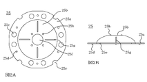
- FIG. 2A is a plan view of the positive electrode lead
- FIG. 2B is a front view
- FIG. 3A is a plan view of the positive electrode current collector
- FIG. 3B is a plan view of a state in which the positive electrode current collector and the positive electrode lead are coupled.
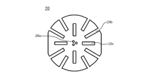
- It is a top view of a negative electrode collector.
- FIG. 5A is a plan view of the connection member of the embodiment
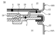
- FIG. 6A is a front view. In the storage battery module of embodiment, it is the front view which showed the connection member in the cross section. It is an expanded sectional view of the VII part of FIG.
- the cylindrical nickel-metal hydride storage battery 10 used in the storage battery module of the embodiment includes a wound electrode body 14 wound with a nickel positive electrode 11 and a hydrogen storage alloy negative electrode 12 insulated from each other via a separator 13. Have.
- the nickel positive electrode 11 is mainly composed of nickel hydroxide in a porous nickel sintered body 16 formed on both surfaces of a positive electrode core 15 made of a nickel-plated steel sheet punching metal, and is composed of zinc hydroxide and cobalt hydroxide.
- the positive electrode active material 17 added from any of the selected compounds is filled.
- a negative electrode mixture layer 19 having a hydrogen storage alloy powder as a negative electrode active material is formed on both surfaces of a negative electrode core 18 made of a nickel-plated mild steel punching metal.
- a negative electrode current collector 20 is resistance-welded to the negative electrode core 18 at the lower part of the wound electrode body 14, and a positive electrode current collector 21 is resistance-welded to the positive electrode core 15 at the upper part of the wound electrode body 14. Yes.
- the wound electrode body 14 is inserted into a metal bottomed cylindrical outer can 22 in which iron is nickel-plated, and the gap between the negative electrode current collector 20 and the bottom of the outer can 22 is a central portion. Spot welded.
- the detailed configuration of the negative electrode current collector 20 will be described later.
- a sealing body 23 in which iron is plated with nickel is caulked and fixed with a gasket 24 being electrically insulated from the outer can 22.
- the positive electrode current collector 21 is integrated by welding a positive electrode current collector lead 25 on the upper surface side, and the positive electrode current collector lead 25 is welded to the sealing body 23 and electrically connected thereto. Detailed configurations of the positive electrode current collector 21 and the positive electrode current collector lead 25 will be described later.
- An opening 26 is provided at the center of the positive electrode current collector 21, and a valve body 27 is disposed in the opening 26 so as to block the opening 26.
- a positive electrode cap 28 is provided on the upper surface of the sealing body 23 so as to cover the periphery of the opening 26 and to be separated from the valve body 27 by a certain distance.
- the positive electrode cap 28 is appropriately provided with a gas vent hole (not shown).
- a spring 29 is provided between the inner surface of the positive electrode cap 28 and the valve body 27, and the valve body 27 is pressed by the spring 29 so as to close the opening 26 of the sealing body 23.
- the valve body 27 has a function as a safety valve for releasing the internal pressure when the internal pressure of the outer can 22 becomes high.
- the positive electrode current collector 21 is formed in a substantially circular shape, and a central opening 21a for inserting a resistance welding electrode is formed at the center, and the end from the periphery of the central opening 21a is formed.
- a large number of burring holes (for example, a diameter of 2 mm, a burring height of 0.4 mm, and a burring thickness of 0.1 mm) 21 b are formed toward the portion.
- a pair of slits 21c opened toward the edge and two pairs of semicircular shapes are provided on the outer peripheral portion of the positive electrode current collector 21. Burring hole 21d is formed.
- the positive electrode current collector lead 25 is formed by pressing so that a nickel-plated steel plate has a predetermined dome shape, and is welded to the positive electrode current collector 21 as shown in FIG. 2A.
- a flat portion 25a formed in a substantially ring shape, and a head portion 25b that is curved from the flat portion 25a and protrudes in a substantially dome shape and is welded to the sealing body 23.
- An opening 25c having the same shape is formed.
- First projection protrusions welded to the positive electrode current collector 21 at substantially equal intervals on the circumference of the substantially center line of the flat portion 25a formed in a substantially ring shape and at positions where the openings 25c are not disposed. 25 d is formed so as to protrude toward the positive electrode current collector 21.
- a semicircular opening 25e having the same shape as the burring hole 21d is formed in the outer peripheral portion of the flat portion 25a at a position corresponding to the semicircular burring hole 21d formed in the outer peripheral portion of the positive electrode current collector 21.
- the opening 25c and the burring hole 21b of the positive electrode current collector 21 communicate with each other to perform the function of an electrolyte injection port, and are positioned when the positive current collector lead 25 is disposed on the positive electrode current collector 21. It is provided to facilitate the process.
- a plurality of slits 25g are radially formed at equal intervals on the top 25b from a position separated from the central opening 25f by a predetermined distance.
- a central opening 25f is formed at the center of the top 25b, and a plurality of second projection protrusions 25h welded to the sealing body 23 at substantially equal intervals around the central opening 25f are formed on the sealing body 23. It is formed so as to protrude toward the surface.
- the negative electrode current collector 20 is formed in a substantially circular shape, and has a plurality of projection protrusions protruding toward the inner surface of the bottom of the outer can 22 (see FIG. 1) at the center. 20a is formed.
- a plurality of slits 20 b that open toward the edge and a position spaced a predetermined distance from the center side in order to reduce the invalid welding current and increase the effective welding current
- a plurality of slits 20c are formed between the first and second edges.
- FIG. A method for producing a cylindrical nickel-metal hydride storage battery 10 using the wound electrode body 14, the positive electrode current collector 21 and the positive electrode current collector lead 25, and the negative electrode current collector 20 configured as described above is shown in FIG. Will be described with reference to FIG.
- the negative electrode current collector 20 is welded to the exposed portion of the negative electrode core 18 of the hydrogen storage alloy negative electrode 12 exposed at the lower end surface of the wound electrode body 14.
- the positive electrode current collector 21 is welded to the exposed portion of the positive electrode core 15 of the nickel positive electrode 11 exposed at the upper end surface of the wound electrode body 14.
- the resistance welding electrode is pressed against the upper surface portion of the first projection protrusion 25d, and the positive electrode current collector lead 25 is attached to the positive electrode current collector 21. Spot weld.
- the positive electrode current collector 21 corresponds to the first current collector in one embodiment of the present invention
- the negative electrode current collector 20 similarly corresponds to the second current collector.
- the wound electrode body 14 to which the negative electrode current collector 20, the positive electrode current collector 21, and the positive electrode current collector lead 25 are welded is housed in a bottomed cylindrical outer can 22 in which nickel is plated on iron.
- a resistance welding electrode is inserted into the space formed at the center of the spirally wound electrode body 14, and abuts on the position where the projection protrusion 20a of the negative electrode current collector 20 is formed, so that the negative electrode current collector 20 is packaged. Spot welding is performed on the inner bottom surface of the can 22.
- a welding mark X (see FIG. 7) is formed between the inner bottom surface of the outer can 22 and the central portion of the negative electrode current collector 20.
- grooving is performed on the outer periphery of the upper portion of the outer can 22 to form an annular recess 22 a at the upper end of the outer can 22.
- an electrolytic solution made of an alkaline aqueous solution containing 7N potassium hydroxide (KOH) is injected into the outer can 22.
- the sealing body 23 is disposed on the positive electrode current collecting lead 25.
- a positive electrode cap 28 serving as a positive electrode external terminal is fixed to the sealing body 23, and a valve element 27 is provided in the positive electrode cap 28.
- An opening 26 for venting gas is formed in the center of the sealing body 23, and a gasket 24 is fitted in advance on the periphery thereof.
- the nickel hydride storage battery 10 as shown in FIG. 1 is obtained by caulking and sealing the opening edge of the outer can 22 inward.
- the storage battery module 50 includes a plurality of nickel metal hydride storage batteries 10 ⁇ / b> A, 10 ⁇ / b> B... Connected in series, and each cylindrical nickel metal hydride storage battery 10 ⁇ / b> A, 10 ⁇ / b> B.
- a connecting member 30 is disposed between them.
- the connecting member 30 is formed by, for example, pressing so that a nickel-plated steel plate has a predetermined dish shape.
- a flat portion 30a formed in a substantially ring shape that is welded to the outer surface of the bottom portion, and a bottom portion 30b that is curved from the flat portion 30a and has a dish-like shape and is welded to the upper surface of the sealing body 23. ing.
- An opening 30c is formed at the center of the bottom 30b, and a plurality of slits 30d are formed at equal intervals so as to extend radially from the opening 30c.
- the opening 30 c is sized so that the positive electrode cap 28 can protrude so that the outer surface of the bottom 30 b can come into contact with the surface of the sealing body 23 when the bottom 30 b of the connecting member 30 is covered from the surface side of the sealing body 23. Is formed.
- the height between the flat portion 30a and the bottom portion 30b of the connecting member 30 is larger than the height of the positive electrode cap 28, and charging / discharging is performed on the storage battery module 50, whereby each of the nickel hydrogen storage batteries 10A, 10B... Height that does not contact the bottom outer surface of the cylindrical outer can 22 of the counterpart nickel-metal hydride storage battery 10A, 10B. 7).
- a plurality of first projection protrusions 30e projecting toward the outer surface of the bottom of the cylindrical outer can 22 are formed on the flat portion 30a, and a plurality of second projections projecting toward the sealing body 23 are formed on the bottom portion 30b.
- a protrusion 30f is formed.
- a plurality of semi-circular openings 30g are formed on the outer periphery of the flat portion 30a.
- the openings 30g and the radially formed slits 30d reduce the reactive current during resistance welding so that the resistance welding current flows in a concentrated manner in the first projection protrusion 30e or the second projection protrusion 30f. Is provided.
- the slits 30d formed radially are charged and discharged with respect to the storage battery module 50, so that when the nickel hydride storage battery 10 expands and contracts, the bottom 30b is easily deformed.
- the connecting member 30 has a function of increasing the thickness of the connecting member 30 so that the connecting member 30 can have a low resistance.
- a method for welding the connecting member 30 will be described. First, the positive electrode cap 28 of the first nickel metal hydride storage battery 10A is inserted into the opening 30c from the dish-shaped bottom side of the connection member 30, and the second projection protrusion 30f of the connection member 30 is brought into contact with the outer surface of the sealing body 23. Let In this state, a resistance welding electrode (not shown) is contacted from the back side of the second projection protrusion 30f, and a predetermined resistance welding current is applied between the sealing body 23 and the resistance welding electrode while applying a predetermined pressing force. And spot welding is performed. As a result, a welding mark Y is formed between the connecting member 30 and the sealing body 23 at the position where the second projection protrusion 30 f is formed.
- the first projection protrusion 30e formed on the flat portion 30a of the connection member 30 is brought into contact with the outer surface of the bottom of the outer can 22 of the second nickel metal hydride storage battery 10B to be connected in series. Then, while applying a predetermined pressing force between the first nickel metal hydride storage battery 10A and the second nickel metal hydride storage battery 10B, the sealing body 23 of the first nickel metal hydride storage battery and the exterior of the second nickel metal hydride storage battery 10B A predetermined resistance welding current is applied to the can 22 to perform spot welding.
- an insulating member is disposed between them.
- a welding mark Z is formed between the outer surface of the bottom of the outer can 22 of the second nickel metal hydride storage battery 10B and the connection member 30 at the position where the first projection protrusion 30e is formed.
- this welding mark Z does not overlap with the position of the slits (20b, 20c) of the negative electrode current collector 20 of the nickel hydrogen battery 10B, there is a place where the contact is unstable on the energized current path at the time of welding the connecting parts. Even if a large current flows without being present, sputtered metal particles are hardly generated, and an internal short circuit of the wound electrode body 14 disposed in the outer can 22 of the second nickel metal hydride storage battery 10B is less likely to occur. . By repeating such an operation, a predetermined number of nickel-metal hydride storage batteries can be connected in series.
- the present invention can also be applied to a case where the outer can side is a positive electrode.
- cylindrical nickel hydride storage battery such as a cylindrical lithium ion secondary battery and a cylindrical nickel cadmium storage battery. Even if applied, the same effects can be obtained.
Landscapes
- Chemical & Material Sciences (AREA)
- Chemical Kinetics & Catalysis (AREA)
- Electrochemistry (AREA)
- General Chemical & Material Sciences (AREA)
- Engineering & Computer Science (AREA)
- Manufacturing & Machinery (AREA)
- Inorganic Chemistry (AREA)
- Connection Of Batteries Or Terminals (AREA)
- Battery Mounting, Suspending (AREA)
Abstract
使用時に内部短絡が発生し難く、信頼性が高い蓄電池モジュールを提供する。 本発明の蓄電池モジュール(50)は、複数の円筒形蓄電池(10A、10B)が接続部材(30)を介して互いに直列に接続され、巻回電極体(14)には、巻回軸の一方側の端部に第1の集電体が正極板及び負極板の一方に溶接され、他方側の端部に第2の集電体(20)が正極板及び負極板の他方に溶接され、第1の集電体は封口体に電気的に接続され、第2の集電体(20)は、周辺にスリットが形成された平板状であり、中心部が円筒状の外装缶(22)の底部内面に溶接されており、接続部材(30)は、一方の面が円筒形蓄電池(10B)の底部外面に、第2の集電体(20)のスリットの位置とは重ならない位置で溶接されており、他方の面が他の円筒形蓄電池(10A)の封口体に溶接されている。
Description
本発明は、複数の円筒状の蓄電池を直列に接続した蓄電池モジュールに関する。
ハイブリッド電気自動車(HEV:Hybrid Electric Vehicle)、プラグインハイブリッド電気自動車(PHEV:Plug-in Hybrid Electric Vehicle)、電気自動車(EV:Electric Vehicle)等の大電流充放電を必要とする用途、又は鉛蓄電池をアイドルストップ機能や減速時のエネルギーを電気エネルギーとして回収する減速エネルギー回生システムを有する車両では、一般的な車両用の電源として汎用されている鉛蓄電池と共に、ニッケル水素蓄電池やリチウム二次電池が多く使用されている。これらの用途は、大電力用のモーターを駆動するため、ニッケル水素蓄電池やリチウム二次電池を多数個直列に接続して蓄電池モジュールを形成し、場合によってはさらにこの蓄電池モジュールを複数個並列に接続し、所定の高電圧で大電流を供給することができるようにしている。
ニッケル水素蓄電池やリチウムイオン二次電池は、金属製の外装体を備える角形のものやラミネート外装体を備える薄板状のものも存在するが、金属製の円筒状外装体を備えた円筒状のものが多く使用されている。これらの円筒状の蓄電池を多数個直列に接続するには、充放電時のそれぞれの電池の膨張・収縮に追従し、さらにそれぞれの電池に設けられている安全弁が所定の圧力で正確に作動できるようにする必要がある。そのため、円筒状の蓄電池を多数個接続してモジュール化するために、種々の接続方法が開発されている。
例えば、下記特許文献1には、一方の電池の封口体の先端部と他方の電池の金属製の外装缶の底部との間に一定の間隔が形成されるように、接続部材を設けた組電池の発明が開示されている。この接続部材は、外周側が他方の電池の外装缶の底部外周側に溶接されているとともに、内周側が一方の電池の封口体の先端に溶接されている。これにより、一方の電池の封口体の先端が他方の電池の外装缶の底部に接触しないようになされているとともに、一方の電池と他方の電池とが直列に接続されている状態となされている。
上記特許文献1に開示されている組電池では、接続部材の外周側が他方の電池の外装缶の底部外周側に溶接されているので、その分だけ外径が増大する。個々の蓄電池でみれば外形の増大値は小さいが、これらの用途では、多数の電池が組み合わされて蓄電池モジュールが形成されているため、無視できない大きさとなる。このような外形の増大化を抑制するには、接続部材のサイズを蓄電池の外形よりも小さくして、接続部材を他方の電池の外装缶の底部に溶接すればよい。
しかしながら、単純に接続部材を他方の電池の外装缶の底部外面に溶接することによって蓄電池モジュールを形成すると、使用中に蓄電池モジュールの電圧が低下しているものが見出された。蓄電池の市場のおける不具合の多くは、電池電圧が低下するいわゆるショートによるものであり、これらの用途などに用いられる多数の蓄電池を直列接続した蓄電池モジュールでは、1セルの蓄電池のショートでも高額な交換費用が必要となる。個々の蓄電池の出荷時には品質チェックが入念に行なわれているが、出荷時の検査のみでは軽微なショートが発生した蓄電池を拭いきることは困難であり、蓄電池モジュールが市場で使用されている間にショートに至ることが大半であった。そのため、多数の蓄電池を直列接続した蓄電池モジュールにおいて、蓄電池のショートに対する本質的な対策が望まれている。
発明者等が蓄電池モジュールのショートを起こした蓄電池を分解して調べたところ、スパッタされた金属粒子が巻回電極体の内部に侵入して内部短絡を起こしていることが主原因であることが分かった。外装缶の底部内面に巻回電極体の集電体を溶接する際には、溶接部は外装缶の内部に挿入される抵抗溶接用電極によって遮蔽されるため、スパッタされた金属粒子は巻回電極体の内部に侵入し難い。そうすると、内部短絡を起こす原因となるスパッタされた金属粒子は、接続部材を蓄電池の外装缶の底部外面に溶接する際に生成するものと考えられる。
本発明の一態様によれば、接続部材を蓄電池の外装缶の底部外面に溶接する際に、蓄電池の内部でスパッタされた金属粒子が発生し難く、使用時に内部短絡が生成し難い蓄電池モジュールを提供することができる。
本発明の一態様によれば、
複数の円筒形蓄電池が接続部材を介して互いに直列に接続され、
前記円筒形蓄電池は、
正極板と負極板とがセパレータを介して互いに絶縁された状態で巻き回された巻回電極体と、
前記巻回電極体及び電解液を収納する、一方極の端子を兼ねる金属製の円筒状外装缶と、
前記円筒状外装缶の開口部に電気的に絶縁された状態で取り付けられた、他方極の端子を兼ねる封口体とを備え、
前記巻回電極体には、巻回軸の一方側の端部に第1の集電体が正極板に溶接され、他方側の端部に第2の集電体が負極板に溶接され、
前記第1の集電体は前記封口体に電気的に接続され、
前記第2の集電体は、周辺にスリットが形成された平板状であり、中心部が前記円筒状外装缶の底部内面に溶接されており、
前記接続部材は、一方の面が前記円筒形蓄電池の底部外面に、前記第2の集電体のスリット位置とは重ならない位置で溶接されており、他方の面が前記他の円筒形蓄電池の前記封口体に溶接されている、
蓄電池モジュール、が提供される。
接続部材と円筒形蓄電池の底部外面への溶接位置が、第2の集電体のスリットの位置と重なっていると、溶接電流の通電経路上に、第2の集電体のスリットエッジ部と、底部内面の接触が不安定な箇所で、金属粒子がスパッタされやすくなる。それに対して、接続部材と円筒形蓄電池の底部外面への溶接位置が、第2の集電体のスリット位置が異なることで、第2の集電体の平板部と、缶部内面が接触状態となり、溶接電流の通電経路が安定するため、金属粒子がスパッタされ難くなる。そのため、本発明の一態様の蓄電池モジュールによれば、使用時に内部短絡が発生し難く、信頼性が高い蓄電池モジュールが得られる。
以下、本発明を実施するための形態について詳細に説明する。ただし、以下に示す実施形態は、本発明の技術思想を理解するために例示するものであって、本発明をこの実施形態に特定することを意図するものではなく、本発明は特許請求の範囲に示した技術思想を逸脱することなく種々の変更を行ったものにも均しく適用し得るものである。
[ニッケル水素蓄電池]
実施形態の蓄電池モジュールで使用した円筒状のニッケル水素蓄電池10は、ニッケル正極11と、水素吸蔵合金負極12とがセパレータ13を介して互いに絶縁された状態で巻き回された巻回電極体14を有している。
実施形態の蓄電池モジュールで使用した円筒状のニッケル水素蓄電池10は、ニッケル正極11と、水素吸蔵合金負極12とがセパレータ13を介して互いに絶縁された状態で巻き回された巻回電極体14を有している。
ニッケル正極11は、ニッケルめっき鋼板製のパンチングメタルからなる正極芯体15の両面に形成された多孔質ニッケル焼結体16内に、水酸化ニッケルを主成分とし、水酸化亜鉛、水酸化コバルトから選択したいずれかの化合物から添加された正極活物質17が充填された構成を有している。水素吸蔵合金負極12は、ニッケルめっきした軟鋼材製のパンチングメタルからなる負極芯体18の両面に負極活物質としての水素吸蔵合金粉末を有する負極合剤層19が形成されている。
巻回電極体14の下部には負極芯体18に負極集電体20が抵抗溶接されており、巻回電極体14の上部には正極芯体15に正極集電体21が抵抗溶接されている。巻回電極体14は、鉄にニッケルめっきを施した金属製の有底円筒状の外装缶22内に挿入されており、負極集電体20と外装缶22の底部との間は中央部でスポット溶接されている。負極集電体20の詳細な構成については後述する。
外装缶22の開放端側には、鉄にニッケルめっきを施した封口体23が、ガスケット24を介して外装缶22とは電気的に絶縁された状態で、カシメ固定されている。正極集電体21は、上面側に正極集電リード25が溶接されて一体化されており、正極集電リード25が封口体23に溶接されて電気的に接続されている。正極集電体21及び正極集電リード25の詳細な構成については後述する。正極集電体21の中央部には開口26が設けられており、この開口26には弁体27が開口26を塞ぐように配置されている。
また、封口体23の上面には、開口26の周囲を覆い、かつ、弁体27とは一定距離だけ隔てた状態となるように、正極キャップ28が設けられている。正極キャップ28には、適宜ガス抜き孔(図示省略)が設けられている。正極キャップ28の内面と弁体27との間にはバネ29が設けられており、弁体27はバネ29によって封口体23の開口26を塞ぐように押圧されている。この弁体27は外装缶22の内部の圧力が高くなった際に、内部の圧力を逃がす安全弁としての機能を有している。
[正極集電体及び正極集電リード]
正極集電体21は、図3Aに示すように、略円形に形成されており、中心部に抵抗溶接用電極挿入用の中心開口21aが形成されているとともに、この中心開口21aの周囲から端部に向けて多数のバーリング孔(例えば、直径2mm、バーリング高さ0.4mm、バーリング厚み0.1mm)21bが形成されている。また、正極集電体21の外周部には、無効な溶接電流を減少させ、有効な溶接電流を増大させるために、端縁に向けて開口する一対のスリット21cと、2対の半円形状のバーリング孔21dが形成されている。
正極集電体21は、図3Aに示すように、略円形に形成されており、中心部に抵抗溶接用電極挿入用の中心開口21aが形成されているとともに、この中心開口21aの周囲から端部に向けて多数のバーリング孔(例えば、直径2mm、バーリング高さ0.4mm、バーリング厚み0.1mm)21bが形成されている。また、正極集電体21の外周部には、無効な溶接電流を減少させ、有効な溶接電流を増大させるために、端縁に向けて開口する一対のスリット21cと、2対の半円形状のバーリング孔21dが形成されている。
正極集電リード25はニッケルめっきが施された鋼板が所定のドーム形状になるように、プレス加工することにより形成されたものであり、図2Aに示すように、正極集電体21に溶接される略リング状に形成された平面部25aと、この平面部25aより湾曲して略ドーム状に突出して形成され、封口体23に溶接される頭頂部25bとを備えている。略リング状に形成された平面部25aの略中心線の円周上で、かつ図3Aに示した正極集電体21に形成された円形のバーリング孔21bに一致する位置に、バーリング孔21bと同形状の開孔25cが形成されている。略リング状に形成された平面部25aの略中心線の円周上で、かつ開孔25cが配置されていない位置には、略等間隔に正極集電体21に溶接される第1プロジェクション突起25dが正極集電体21に向けて突出するように形成されている。
平面部25aの外周部には、正極集電体21の外周部に形成された半円形状のバーリング孔21dに一致する位置に、バーリング孔21dと同形状の半円形状の開孔25eが形成されている。この開孔25cと正極集電体21のバーリング孔21bとは、互いに連通して電解液の注液口の機能を奏するとともに、正極集電リード25を正極集電体21に配置する際の位置決めを容易にするために設けられるものである。
また、頭頂部25bには、中心開口25fから所定の距離だけ離間した位置から放射状に複数のスリット25gが等間隔に形成されている。また、頭頂部25bの中心部には中心開口25fが形成されているとともに、この中心開口25fの周囲に略等間隔に封口体23に溶接される複数の第2プロジェクション突起25hが封口体23に向けて突出するように形成されている。これらの複数のスリット25gを形成すると、電池の封口時の封口体23からの押圧力によりドーム状の頭頂部25bが変形しやすくなるので、正極集電リード25の板厚を厚くして低抵抗の正極集電リード25とすることが可能となる。
[負極集電体]
また、負極集電体20は、図4に示したように、略円形に形成されており、中心部に外装缶22(図1参照)の底部内面側に向かって突出する複数個のプロジェクション突起20aが形成されている。負極集電体20の外周部には、無効な溶接電流を減少させ、有効な溶接電流を増大させるために、端縁に向けて開口する複数のスリット20bと、中心側から所定距離離間した位置から端縁との間に開口する複数のスリット20cとが形成されている。
また、負極集電体20は、図4に示したように、略円形に形成されており、中心部に外装缶22(図1参照)の底部内面側に向かって突出する複数個のプロジェクション突起20aが形成されている。負極集電体20の外周部には、無効な溶接電流を減少させ、有効な溶接電流を増大させるために、端縁に向けて開口する複数のスリット20bと、中心側から所定距離離間した位置から端縁との間に開口する複数のスリット20cとが形成されている。
[ニッケル水素蓄電池の組み立て]
上述のような構成の巻回電極体14と、正極集電体21及び正極集電リード25と、負極集電体20とを用いて、円筒状のニッケル水素蓄電池10を作製する方法について図1を参照しながら説明する。まず、巻回電極体14の下端面に露出する水素吸蔵合金負極12の負極芯体18の露出部に負極集電体20を溶接する。また、巻回電極体14の上端面に露出するニッケル正極11の正極芯体15の露出部に正極集電体21を溶接する。その後、正極集電体21の上に正極集電リード25を配置した後、第1プロジェクション突起25dの上面部に抵抗溶接用電極を押し当てて、正極集電体21に正極集電リード25をスポット溶接する。ここでは、正極集電体21が本発明の一態様における第1の集電体に対応し、同じく負極集電体20が第2の集電体に対応する。
上述のような構成の巻回電極体14と、正極集電体21及び正極集電リード25と、負極集電体20とを用いて、円筒状のニッケル水素蓄電池10を作製する方法について図1を参照しながら説明する。まず、巻回電極体14の下端面に露出する水素吸蔵合金負極12の負極芯体18の露出部に負極集電体20を溶接する。また、巻回電極体14の上端面に露出するニッケル正極11の正極芯体15の露出部に正極集電体21を溶接する。その後、正極集電体21の上に正極集電リード25を配置した後、第1プロジェクション突起25dの上面部に抵抗溶接用電極を押し当てて、正極集電体21に正極集電リード25をスポット溶接する。ここでは、正極集電体21が本発明の一態様における第1の集電体に対応し、同じく負極集電体20が第2の集電体に対応する。
この後、負極集電体20、正極集電体21及び正極集電リード25が溶接された巻回電極体14を鉄にニッケルめっきを施した有底筒状の外装缶22内に収納する。そして、巻回電極体14の中心部に形成された空間部に抵抗溶接用電極を挿入し、負極集電体20のプロジェクション突起20aが形成された位置に当接し、負極集電体20を外装缶22の内底面にスポット溶接する。これにより負極集電体20の中央部には、外装缶22の内底面との間に溶接痕X(図7参照)が形成される。
次いで、外装缶22の上部外周側に溝入れ加工を施し、外装缶22の上端部に環状凹部22aを形成する。この後、外装缶22内に7Nの水酸化カリウム(KOH)を含むアルカリ水溶液からなる電解液を注入する。この後、正極集電リード25上に封口体23を配置する。ここで、封口体23には、正極外部端子となる正極キャップ28が固定されており、正極キャップ28内には弁体27とが設けられている。封口体23の中央にはガス抜き用の開口26が形成されているとともに、その周縁には予めガスケット24が嵌着されている。
次いで、封口体23の上部と外装缶22の下部に一対の溶接電極を配置した後、一対の溶接電極間に予め定めた圧力を負荷しながら抵抗溶接を行う。これにより、正極集電リード25の頭頂部25bに形成された第2プロジェクション突起25hが溶接点となって、封口体23が正極集電リード25に溶接される。この後、外装缶22の開口端縁を内方にかしめて封口することにより、図1に示すようなニッケル水素蓄電池10が得られる。
[蓄電池モジュールの作製]
次に上述の円筒状のニッケル水素蓄電池を複数個直列に接続した蓄電池モジュールについて図5~図7を用いて説明する。この蓄電池モジュール50は、例えば図6に示したように、複数個のニッケル水素蓄電池10A、10B・・・が直列接続されたものであり、それぞれの円筒状のニッケル水素蓄電池10A、10B・・・の間には接続部材30が配置されている。
次に上述の円筒状のニッケル水素蓄電池を複数個直列に接続した蓄電池モジュールについて図5~図7を用いて説明する。この蓄電池モジュール50は、例えば図6に示したように、複数個のニッケル水素蓄電池10A、10B・・・が直列接続されたものであり、それぞれの円筒状のニッケル水素蓄電池10A、10B・・・の間には接続部材30が配置されている。
接続部材30は、図5に示したように、例えばニッケルめっきが施された鋼板が所定の皿状になるように、プレス加工することにより形成されたものであり、円筒状の外装缶22の底部外面に溶接される略リング状に形成された平面部30aと、この平面部30aより湾曲して皿状に窪んだ形状を有し、封口体23の上面に溶接される底部30bとを備えている。底部30bの中央部には開口30cが形成されており、この開口30cからは放射状に部分的に延在するように複数のスリット30dが等間隔に形成されている。
開口30cは、接続部材30の底部30bを封口体23の表面側からかぶせた際に、底部30bの外面が封口体23の表面に接触することができるように、正極キャップ28が突出できる大きさに形成されているものである。接続部材30の平面部30aと底部30bとの間の高さは、正極キャップ28の高さよりも大きく、かつ、蓄電池モジュール50に対して充放電が行われることにより、それぞれのニッケル水素蓄電池10A、10B・・・に膨張・収縮が生じても、正極キャップ28の先端が直列接続される相手方のニッケル水素蓄電池10A、10B・・・の円筒状の外装缶22の底部外面に接触しない高さ(図7参照)とされている。
平坦部30aには円筒状の外装缶22の底部外面に向かって突出する複数の第1プロジェクション突起30eが形成されており、底部30bには封口体23側に向かって突出する複数の第2プロジェクション突起30fが形成されている。
平面部30aの外周部には、正複数個の半円形状の開孔30gが形成されている。この開孔30g及び放射状に形成されたスリット30dは、抵抗溶接時の無効電流を減らして、抵抗溶接用電流が第1プロジェクション突起30eないし第2プロジェクション突起30fに集中して流れるようにするために設けられている。また、放射状に形成されたスリット30dは、蓄電池モジュール50に対して充放電が行われることにより、それぞれのニッケル水素蓄電池10に膨張・収縮が生じた際に、底部30bが変形しやすくなるので、接続部材30の板厚を厚くして低抵抗の接続部材30とすることを可能とする機能をも有している。
この接続部材30の溶接方法を説明する。最初に第1のニッケル水素蓄電池10Aの正極キャップ28を接続部材30の皿状の底部側から開口30c内に挿通し、接続部材30の第2プロジェクション突起30fを封口体23の外表面に当接させる。この状態で第2プロジェクション突起30fの裏側から抵抗溶接用電極(図示省略)を当接させ、所定の押圧力を印加しながら封口体23と抵抗溶接用電極との間に所定の抵抗溶接用電流を印加し、スポット溶接を行う。これにより第2プロジェクション突起30fが形成されていた位置において、接続部材30と封口体23との間に溶接痕Yが形成される。
次いで、直列に接続させる第2のニッケル水素蓄電池10Bの外装缶22の底部外面に接続部材30の平坦部30aに形成されている第1プロジェクション突起30eを当接させる。そして、第1のニッケル水素蓄電池10Aと第2のニッケル水素蓄電池10Bとの間に所定の押圧力を印加しながら、第1のニッケル水素蓄電池の封口体23と第2のニッケル水素蓄電池10Bの外装缶22との間に所定の抵抗溶接用電流を印加し、スポット溶接を行う。この際、第1のニッケル水素蓄電池10Aの封口体23と第2のニッケル水素蓄電池10Bの外装缶22との間の短絡を防止する目的で、両者の間に絶縁部材を配置しておく。これにより第1プロジェクション突起30eが形成されていた位置において、第2のニッケル水素蓄電池10Bの外装缶22の底部外面と接続部材30との間に溶接痕Zが形成される。
この溶接痕Zは、ニッケル水素電池の10Bの負極集電体20のスリット(20b、20c)の位置と重なっていないので、接続部品溶接時の通電電流経路上に、接触が不安定な箇所が存在せず、大電流が流れても、スパッタされた金属粒子が発生し難く、第2のニッケル水素蓄電池10Bの外装缶22内に配置されている巻回電極体14の内部短絡が生じ難くなる。このような操作を繰り返すことにより、所定数のニッケル水素蓄電池を直列接続することができる。
なお、上記実施形態では、外装缶側が負極となるようにした例を示したが、逆に外装缶側が正極となるようにした場合においても適用可能である。また、上記実施形態では、円筒状のニッケル水素蓄電池の場合について適用した場合を示したが、円筒状のリチウムイオン二次電池や円筒状のニッケルカドミウム蓄電池等、円筒状の蓄電池の場合に対して適用しても、同様の作用効果を奏する。
10、10A、10B…ニッケル水素蓄電池
11…ニッケル正極
12…水素吸蔵合金負極
13…セパレータ
14…巻回電極体
15…正極芯体
16…多孔質ニッケル焼結体
17…正極活物質
18…負極芯体
19…負極合剤層
20…負極集電体
20a…プロジェクション突起
20b、20c…スリット
21…正極集電体
21…正極集電体
21a…中心開口
21b、21d…バーリング孔
21c…スリット
22…外装缶
22a…環状凹部
23…封口体
24…ガスケット
25…正極集電リード
25a…平面部
25b…頭頂部
25c、25e…開孔
25d、25h…プロジェクション突起
25f…中心開口
25g…スリット
26…開口
27…弁体
28…正極キャップ
29…バネ
30…接続部材
30a…平面部
30b…底部
30c…開口
30d…スリット
30e、30f…プロジェクション突起
30g…半円形状の開孔
30a…平坦部
50…蓄電池モジュール
X、Y、Z…溶接痕
Claims (4)
- 複数の円筒形蓄電池が接続部材を介して互いに直列に接続され、
前記円筒形蓄電池は、
正極板と負極板とがセパレータを介して互いに絶縁された状態で巻き回された巻回電極体と、
前記巻回電極体及び電解液を収納する、一方極の端子を兼ねる金属製の円筒状外装缶と、
前記円筒状外装缶の開口部に電気的に絶縁された状態で取り付けられた、他方極の端子を兼ねる封口体とを備え、
前記巻回電極体には、巻回軸の一方側の端部に第1の集電体が正極板及び負極板の一方に溶接され、他方側の端部に第2の集電体が正極板及び負極板の他方に溶接され、
前記第1の集電体は前記封口体に電気的に接続され、
前記第2の集電体は、周辺にスリットが形成された平板状であり、中心部が前記円筒状外装缶の底部内面に溶接されており、
前記接続部材は、一方の面が前記円筒形蓄電池の底部外面に、前記第2の集電体のスリット位置とは重ならない位置で溶接されており、他方の面が他の円筒形蓄電池の前記封口体に溶接されている、
蓄電池モジュール。 - 前記接続部材は、前記一方の円筒形蓄電池の円筒状外装缶の底部外面と前記他方の円筒形蓄電池の封口体との間に、予め定めた一定距離の隙間が形成されるように、皿状とされている、請求項1に記載の蓄電池モジュール。
- 前記接続部材には中心部に開口が形成されており、
前記封口体には一方極の端子となる突起が形成されており、
前記接続部材は、
前記皿状の底部から前記突起が突出するように、前記開口に前記突起が挿入され、前記突起の周囲で前記他方の円筒形蓄電池の前記封口体に溶接されているとともに、前記皿状の縁側で前記一方の円筒形蓄電池の底部外面に溶接されている、請求項2に記載の蓄電池モジュール。 - 前記接続部材は、
前記他方の円筒形蓄電池の封口体との間の溶接部に前記封口体側に向かって突出する凸部と、前記一方の円筒形蓄電池の底部外面側に向かって突出する凸部とが形成されており、前記凸部でそれぞれ前記他方の円筒形蓄電池の封口体及び前記一方の円筒形蓄電池の底部外面と溶接されている、請求項1~3のいずれかに記載の蓄電池モジュール。
Applications Claiming Priority (2)
| Application Number | Priority Date | Filing Date | Title |
|---|---|---|---|
| JP2012239414A JP2016012393A (ja) | 2012-10-30 | 2012-10-30 | 蓄電池モジュール |
| JP2012-239414 | 2012-10-30 |
Publications (1)
| Publication Number | Publication Date |
|---|---|
| WO2014068869A1 true WO2014068869A1 (ja) | 2014-05-08 |
Family
ID=50626822
Family Applications (1)
| Application Number | Title | Priority Date | Filing Date |
|---|---|---|---|
| PCT/JP2013/006086 Ceased WO2014068869A1 (ja) | 2012-10-30 | 2013-10-11 | 蓄電池モジュール |
Country Status (2)
| Country | Link |
|---|---|
| JP (1) | JP2016012393A (ja) |
| WO (1) | WO2014068869A1 (ja) |
Cited By (2)
| Publication number | Priority date | Publication date | Assignee | Title |
|---|---|---|---|---|
| CN113363635A (zh) * | 2019-05-15 | 2021-09-07 | 广东微电新能源有限公司 | 纽扣型电池及其制造方法 |
| CN116845441A (zh) * | 2023-07-03 | 2023-10-03 | 蜂巢能源科技股份有限公司 | 电池及电池包 |
Families Citing this family (1)
| Publication number | Priority date | Publication date | Assignee | Title |
|---|---|---|---|---|
| WO2023047925A1 (ja) * | 2021-09-22 | 2023-03-30 | パナソニックIpマネジメント株式会社 | 蓄電デバイス用の集電板、蓄電デバイス、および蓄電デバイスの製造方法 |
Citations (5)
| Publication number | Priority date | Publication date | Assignee | Title |
|---|---|---|---|---|
| JP2006156135A (ja) * | 2004-11-30 | 2006-06-15 | Gs Yuasa Corporation:Kk | 密閉形電池とその製造方法及び密閉形電池の複数個で構成した組電池 |
| JP2007066604A (ja) * | 2005-08-30 | 2007-03-15 | Sanyo Electric Co Ltd | 二次電池および電池モジュール |
| JP2009206024A (ja) * | 2008-02-29 | 2009-09-10 | Sanyo Electric Co Ltd | 組電池 |
| JP2009245733A (ja) * | 2008-03-31 | 2009-10-22 | Sanyo Electric Co Ltd | モジュール電池 |
| JP2011100661A (ja) * | 2009-11-06 | 2011-05-19 | Toyota Motor Corp | 組電池 |
-
2012
- 2012-10-30 JP JP2012239414A patent/JP2016012393A/ja active Pending
-
2013
- 2013-10-11 WO PCT/JP2013/006086 patent/WO2014068869A1/ja not_active Ceased
Patent Citations (5)
| Publication number | Priority date | Publication date | Assignee | Title |
|---|---|---|---|---|
| JP2006156135A (ja) * | 2004-11-30 | 2006-06-15 | Gs Yuasa Corporation:Kk | 密閉形電池とその製造方法及び密閉形電池の複数個で構成した組電池 |
| JP2007066604A (ja) * | 2005-08-30 | 2007-03-15 | Sanyo Electric Co Ltd | 二次電池および電池モジュール |
| JP2009206024A (ja) * | 2008-02-29 | 2009-09-10 | Sanyo Electric Co Ltd | 組電池 |
| JP2009245733A (ja) * | 2008-03-31 | 2009-10-22 | Sanyo Electric Co Ltd | モジュール電池 |
| JP2011100661A (ja) * | 2009-11-06 | 2011-05-19 | Toyota Motor Corp | 組電池 |
Cited By (2)
| Publication number | Priority date | Publication date | Assignee | Title |
|---|---|---|---|---|
| CN113363635A (zh) * | 2019-05-15 | 2021-09-07 | 广东微电新能源有限公司 | 纽扣型电池及其制造方法 |
| CN116845441A (zh) * | 2023-07-03 | 2023-10-03 | 蜂巢能源科技股份有限公司 | 电池及电池包 |
Also Published As
| Publication number | Publication date |
|---|---|
| JP2016012393A (ja) | 2016-01-21 |
Similar Documents
| Publication | Publication Date | Title |
|---|---|---|
| JP6228127B2 (ja) | 円筒形蓄電池及び蓄電池モジュール | |
| JP6208687B2 (ja) | 円筒形二次電池及びその製造方法 | |
| CN111213257A (zh) | 能量储存装置和能量储存模块 | |
| US20110206958A1 (en) | Sealed battery | |
| JP5342090B1 (ja) | 蓄電素子 | |
| JP2008243811A (ja) | 電池 | |
| JP2009110885A (ja) | 密閉電池及びその製造方法 | |
| JP5018087B2 (ja) | 密閉形電池、密閉形電池用リード、及び密閉形電池の複数個で構成した組電池 | |
| KR20220155017A (ko) | 이차 전지 | |
| CN114175391B (zh) | 电池 | |
| CN111183536A (zh) | 能量储存装置和制造能量储存装置的方法 | |
| US20090029244A1 (en) | Battery, and battery manufacturing method | |
| JP2008192321A (ja) | 円筒型蓄電池およびその製造方法 | |
| JP2016012393A (ja) | 蓄電池モジュール | |
| JP5183251B2 (ja) | 組電池 | |
| JP4251829B2 (ja) | 電池およびその製造方法 | |
| JP4465754B2 (ja) | 密閉型電池 | |
| JP4079563B2 (ja) | 蓄電池およびその製造方法 | |
| JP2019200859A (ja) | 密閉型電池 | |
| JP2014150047A (ja) | 蓄電素子 | |
| JP5159076B2 (ja) | 円筒型蓄電池およびその製造方法 | |
| KR101453782B1 (ko) | 이차 전지 및 이를 제조하는 방법 | |
| JP2005285514A (ja) | 円筒型電池およびその製造方法 | |
| JP2007066604A (ja) | 二次電池および電池モジュール | |
| CN119856335A (zh) | 电池 |
Legal Events
| Date | Code | Title | Description |
|---|---|---|---|
| 121 | Ep: the epo has been informed by wipo that ep was designated in this application |
Ref document number: 13851059 Country of ref document: EP Kind code of ref document: A1 |
|
| NENP | Non-entry into the national phase |
Ref country code: DE |
|
| 122 | Ep: pct application non-entry in european phase |
Ref document number: 13851059 Country of ref document: EP Kind code of ref document: A1 |
|
| NENP | Non-entry into the national phase |
Ref country code: JP |