WO2014068757A1 - 情報処理システム、データ管理方法及びプログラム - Google Patents
情報処理システム、データ管理方法及びプログラム Download PDFInfo
- Publication number
- WO2014068757A1 WO2014068757A1 PCT/JP2012/078383 JP2012078383W WO2014068757A1 WO 2014068757 A1 WO2014068757 A1 WO 2014068757A1 JP 2012078383 W JP2012078383 W JP 2012078383W WO 2014068757 A1 WO2014068757 A1 WO 2014068757A1
- Authority
- WO
- WIPO (PCT)
- Prior art keywords
- server
- data
- service
- program
- user terminal
- Prior art date
- Legal status (The legal status is an assumption and is not a legal conclusion. Google has not performed a legal analysis and makes no representation as to the accuracy of the status listed.)
- Ceased
Links
Images









Classifications
-
- H—ELECTRICITY
- H04—ELECTRIC COMMUNICATION TECHNIQUE
- H04L—TRANSMISSION OF DIGITAL INFORMATION, e.g. TELEGRAPHIC COMMUNICATION
- H04L67/00—Network arrangements or protocols for supporting network services or applications
- H04L67/01—Protocols
- H04L67/12—Protocols specially adapted for proprietary or special-purpose networking environments, e.g. medical networks, sensor networks, networks in vehicles or remote metering networks
-
- H—ELECTRICITY
- H04—ELECTRIC COMMUNICATION TECHNIQUE
- H04L—TRANSMISSION OF DIGITAL INFORMATION, e.g. TELEGRAPHIC COMMUNICATION
- H04L67/00—Network arrangements or protocols for supporting network services or applications
- H04L67/50—Network services
- H04L67/52—Network services specially adapted for the location of the user terminal
Definitions
- the present invention relates to an information processing system and a data management method, and is preferably applied to an information processing system, a data management method, and a program that provide a user with high service response performance using a plurality of distributed servers. It will be.
- a form in which a processing result is transmitted to a terminal device by using a processing function of an information processing device disposed in a central data center has become common.
- the processing is concentrated on information processing devices such as servers and storages in the data center, and the information processing device is operated from an external computer in which the user is connected to the data center via a network. It is common to use With cloud computing, it is possible to reduce system construction costs and running costs by concentrating information processing on the data center.
- the quality of a response to an information processing request means so-called data throughput or response time.
- data center operators and operators who borrow equipment from data center operators and use them for hosting businesses or use them in-house are distributed information processing devices on a wide-area network.
- Is used for load balancing Specifically, the operator distributes applications and data copies on a plurality of distributed information processing devices, and takes load balancing measures by reducing the frequency of use of information processing devices in the central data center. Yes. Thereby, the quality of the response to the information processing request is maintained.
- a load balancing technique for example, a content delivery network (CDN) disclosed in Patent Document 1 can be cited.
- the CDN technology described in Patent Document 1 is mainly intended to distribute data such as digital contents such as music and moving pictures to the vicinity of users.
- content distribution bases servers
- servers are prepared at various locations on the network close to users who use the content. Then, by instructing access to an appropriate distribution base according to the position of the user, a large amount of content can be smoothly distributed to the user. In this way, the distribution load is distributed from the central data center or the server that owns the original content, thereby reducing the network load.
- the present invention has been made in consideration of the above points.
- the present invention provides an information processing system in which one or more servers and one or more sensors are distributed and connected via a network, and the servers collect from the sensors.
- a storage unit that stores the sensor data
- a control unit that controls execution of a service program that provides a predetermined service based on the sensor data in response to a request from a user terminal.
- An information processing system for transmitting the sensor data to a server in the vicinity of the requested user terminal, connecting the user terminal to the server, and executing the service program on the server Is provided.
- a service requested by the user on a server near the user terminal used by the user is provided.
- the corresponding service program is executed. Accordingly, it is possible to process and distribute sensor information in consideration of user convenience while suppressing waste of network and server resources.
- FIG. 3 is a block diagram showing a configuration of software according to the embodiment. It is a chart showing an example of a server table concerning the embodiment. It is a chart showing an example of an area table concerning the embodiment. It is a chart which shows an example of the unprocessed data table concerning the embodiment. It is a chart which shows an example of the processing data table concerning the embodiment. It is a chart which shows an example of the data replication table concerning the embodiment. It is a chart which shows an example of the service program table concerning the embodiment. It is a chart which shows an example of the service utilization condition table concerning the embodiment.
- program is used as the subject.
- the program performs processing determined by being executed by the processor using the memory and the communication port (communication control device)
- the processor is used as the subject.
- the explanation may be as follows. Further, the processing disclosed with the program as the subject may be processing performed by a computer such as a management server or an information processing apparatus. Further, part or all of the program may be realized by dedicated hardware.
- Various programs may be installed in each computer by a program distribution server or a storage medium that can be read by the computer.
- the servers are distributed. Since data is uniformly distributed to each server, content distribution to an unused area occurs. As a result, the server capacity is wasted and the network load accompanying data transmission to the entire distributed system increases or the response performance decreases.
- a service desired by the user cannot be provided simply by caching the data in the server.
- simply providing data to the server can provide necessary information to the user.
- FIG. 1 shows the configuration of the information processing system according to this embodiment.
- the information processing system according to this embodiment includes a plurality of areas 101 of area A, area B, area C, area D, and area E.
- Each area includes a server 103, a sensor 102, and a terminal device 106 that uses a service provided by the server 103.
- Various devices are connected via the network 104.
- the area 101 a sensor 102, a server 103, and a management server 105 are installed.
- the area is a predetermined specific area such as a geographical division such as a town, city, prefecture, region, or country, or a data center, a server room, or an in-house building.
- each area may overlap.
- an area AB including area A and area B may be defined as one area.
- the sensor 102 is a device for measuring and collecting various information such as a moving image, a still image, sound, and temperature, and a sensor corresponding to a service provided to the user is arranged.
- One service may use a plurality of sensors 102.
- the sensor 102 is connected to the server 103 via the network 104, and data collected by the sensor 102 is stored in a storage included in the server 103.
- the server 103 is an application server that collects and accumulates sensor information and performs information processing for providing services to users.
- the server 103 collects and accumulates information of the sensor 102, processes information collected from the sensor 102, executes a service program that uses the processed data, and transmits, copies, and references data between servers in cooperation with other servers. Perform each process.
- the server 103 may collect information from a plurality of sensors 102 or may collect information from a plurality of different types of sensors 102. The configuration of the server 103 will be described later in detail.
- the network 104 is a network for connecting the sensor 102, the server 103, the management server 105, and the terminal device 106 to transmit / receive data between the components.
- the network 104 can be exemplified by a LAN, a WAN, a wireless LAN, or the like, but may take other forms as long as data can be transmitted and received.
- the management server 105 is a server for monitoring and controlling each device in the area.
- the service program is arranged and started, and data transmission and replication with other servers are executed.
- the overall management server 107 is a server for managing the entire information processing system.
- the overall management server 107 manages the status of services operating in the information processing system, manages the service usage status of the terminal device 106, manages each data stored in the server 103, and the like.
- the terminal device 106 is a PC (Personal Computer) or a smart terminal used by a user to connect to the service and use the service.
- the terminal device 106 is connected to the server 103, the management server 105, and the overall management server 107 via a wired or wireless network 104.
- the terminal device 106 is illustrated in each area 101. However, when the terminal device 106 is a mobile terminal, the terminal device 106 moves together with the movement of the user of the terminal device 106, and the previous service is provided. You may connect to the server from an area that is different from the area that uses.
- Each area 101 includes the sensors 102, the server 103, the management server 105, and the terminal device 106, but depending on the form of the information processing system, only the service is provided and the sensor 102 does not exist. There may be an area where the terminal device 106 does not exist.
- FIG. 2 shows a hardware configuration of a computer that realizes the server 103.
- the server 103 includes a CPU 201, a memory 202, a storage 203, an input / output device 204, and a network interface 205.
- the CPU 201 functions as an arithmetic processing unit and a control unit, and controls the overall operation in the server 103 according to various programs. Further, the CPU 201 may be a microprocessor.
- the memory 202 temporarily stores programs used in the execution of the CPU 201, parameters that change as appropriate during the execution, and the like.
- the storage 203 is a device that stores a program and data used by the program, and can be exemplified by an HDD or an SSD.
- the input / output device 204 includes an input device that inputs a program that runs on the server, and an output device that outputs the program.
- the input device is, for example, an input means for a user to input information, such as a mouse, keyboard, touch panel, button, microphone, switch, and lever, and input control that generates an input signal based on the input by the user and outputs it to the CPU 201 It consists of a circuit.
- the output device includes, for example, a display device such as a CRT (Cathode Ray Tube) display device, a liquid crystal display (LCD) device, an OLED (Organic Light Emitting Display) device and a lamp, and an audio output device such as a speaker and headphones.
- CTR Cathode Ray Tube
- LCD liquid crystal display
- OLED Organic Light Emitting Display
- the network interface 205 is an interface for the server 103 to connect to an external computer, and provides a function of connecting by wire or wireless depending on the network configuration.
- Each program may be stored in the storage 203 in advance, or may be acquired from another server via the network 104 as necessary.
- the storage 203 may be arranged in the server, or arranged in a device outside the server connected via the network interface 205, the network 104, LAN, SAN, IP-SAN, or the like. Also good.
- the management server 105, the terminal device 106, and the overall management server 107 have the same hardware configuration except that the program operating on the memory 202 and the data stored in the storage 203 are different. Omitted.
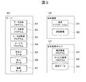
- FIG. 3 shows the configuration of software that runs on the server 103, the management server 105, and the terminal device 106.
- the software of the server 103 includes a data collection program 301, a data processing program 302, a data transmission / reception program 303, a service program 304, raw data 305, processed data 306, and replicated data 307.
- the data collection program 301 is a program that receives data transmitted from the sensor 102 and stores the data as raw data 305.
- the data collection program 301 performs processing according to the type of the sensor 102. For example, in the case of a server to which a monitoring camera is connected as the sensor 102, moving image or still image data transmitted from the monitoring camera is stored in an appropriate format.
- the data processing program 302 refers to the raw data 305 collected and accumulated from the sensor and is processed into a format, size, and content suitable for the service program 304.
- the data processing program 302 is a program that operates according to the sensor 102 connected to the server 103 and the service program 304. For example, in the case of a service that provides an image of a remote monitoring camera to a user, the data processing program 302 reduces the frame rate of the raw data 305 having a large size and high resolution acquired from the sensor 102, thereby suppressing the network load. Perform processing to an appropriate size.
- the data processing program 302 includes feature points extracted by analyzing the raw data 305. Data is generated as processed data 306.
- the data transmission / reception program 303 is a program that refers to the raw data 305 and the processed data 306, transmits data to the other server 103, copies it, or receives and copies the data from another server.
- data is transmitted / received in cooperation with the data transmission / reception program 303 of the other server 103, and is stored as the replicated data 307.
- Data transmission, replication destination and transmission, and replication timing are executed in response to instructions from the overall management server 107 described later.
- the service program 304 when the service program 304 is not arranged, it also has a function of acquiring and arranging a service program from another server.
- the service program 304 is a program that provides a service to the user by using various data stored in the information processing system.
- the service program 304 receives a request from the terminal device 106 used by the user, the service program 304 returns a response with reference to the processing data 306 used by the own service.
- the service is provided by referring to the processed data or the replicated data stored in another server.
- the server 103 when the server 103 does not have the sensor 102 and is a server that provides only the service, the server 103 includes only the data transmission / reception program 303, the service program 304, and the replicated data 307.
- the software of the terminal device 106 includes a terminal application 321 and connection information 322.
- the terminal application 321 is an application program directly used by the user, and provides a service to the user in cooperation with the service program 304 operating on the server 103.
- the connection information 322 is information indicating the location of a server on which a service program accessed by the terminal application 321 operates, and includes a service URL, a server IP address, or a port number.
- the software of the overall management server 107 includes a configuration management program 331, a service management program 332, and management data 333.
- the configuration management program 331 is a program for managing the association, system configuration, and data arrangement of devices, programs, and data in the information processing system, collecting configuration information from information devices in each area, A function for notifying the server of configuration information and a program for acquiring the configuration information.
- the service management program 332 is a program for managing the usage status of the user's service, and is a program for managing which service the user uses and from which area the user uses the service.
- Management data 333 Information managed by the configuration management program 331 and the service management program 332 is stored in the storage as management data 333.
- the configuration management program 331 and the service management program 332 have a function of communicating with an external program. For notification and acquisition of configuration information and information related to services, for example, information is transmitted in XML or REST format on a protocol such as HTTP / HTTPS. Sent and received.
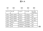
- FIG. 4A is a server table 400 that manages the relationship between the area 101 in which the server 103 is arranged, the sensor 102 that transmits data to the server 103, and the service program 304 that operates on the server 103.
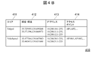
- FIG. 4B is an area table 410 indicating the area to which the server 103 belongs.
- the server table 400 is defined by the system administrator and stored as a part of the management data 333 of the overall management server 107 when there is a change in the system configuration or service configuration, such as when the server is installed or when the service program is registered.
- the server table 400 includes a server column 401, a sensor column 402, an area 1 column 403, an area 2 column 404, and a service program column 405.
- an ID indicating the server 103 is stored in the server column 401.
- the ID indicating the server 103 is a host name and an IP address of the server 103 and is a unique value in the server 103 connected to the information processing system.
- the sensor column 402 stores an ID indicating the sensor 102 that is connected to the server 103 and collects the raw data 305 stored in the server 103.
- the ID indicating the sensor 102 is a value that can uniquely identify the sensor 102 in the information processing system.
- a plurality of sensors 102 are connected to the server 103, a plurality of values are concatenated and stored with commas. When there is no sensor 102, “null” is set. When there are a plurality of sensors 102, a value obtained by connecting IDs of the sensors 102 with commas is set.
- the area 1 column 403 stores an area 101 where the server 103 or the sensor 102 is arranged, and an ID for identifying a narrow area such as a city or prefecture.
- the area 2 column 404 is an area 101 in which servers or sensors are arranged, and stores IDs for identifying wide areas such as regions and countries.
- area 1 and area 2 are defined based on geographical distances, but facilities such as data centers and stores may be used as units. Further, delay and throughput may be ranked as network characteristics, and each rank may be defined as an area.
- the area where the business unit server is arranged is managed in two stages, a near area and a wide area, it may be managed in three or more stages.
- the servers and sensors included in each area may overlap. Moreover, you may define the area of only the server which does not have a sensor.
- an ID for identifying the service program 304 operating on the server 103 is stored. If no service is arranged, “null” is set. When a plurality of services operate, a value obtained by separating the service IDs with commas such as “SP-1, SP-2” is set. The value in the service program column 405 is updated to a value related to the server in the area near the user according to the user's usage pattern.
- the sensors “SEN-1” and “SEN-2” are connected to the server “SVR-1”, and the server “SVR-1” belongs to the “Tokyo1” area and the “EastJapan” area. It can be seen that the service program providing the service “SP-1” is operating.
- the area table 410 is displayed by the system administrator when adding or changing / deleting an area definition when there is a change in the system configuration or service configuration, such as server installation, sensor installation, or service program registration. It is updated and stored as a part of the management data 333 of the overall management server 107.
- the area table 410 includes an area column 411, a latitude / longitude column 412, an IP address column 413, and an access point column 414.
- the latitude / longitude column 412 stores a value indicating the geographical range of the area column 411.
- the format of the value is set in the format of x1, y1-x2, y2 for the latitude point x1 and longitude y1 for the northwest point and the latitude x2 and longitude y2 for the southeast point for a rectangular area that cuts out a range on the map Is done.
- IP addresses assigned to servers, sensors, or terminal devices in the area 411 are set. When there are a plurality of IP addresses, they are set by separating them with commas. When the range of IP addresses is specified collectively, the start address and the end address are connected by a hyphen as in 10.208.10.1-255. For example, when the IP address 10.208.10.1-255 is set for the area “Tokyo 1”, the terminal device 106 having the IP address 10.208. Belongs to the area “Tokyo1”.
- the access point column 414 stores a value for identifying an access point such as a wireless LAN device included in the area.
- an access point such as a wireless LAN device included in the area.
- At least one value may be set in the latitude / longitude column 412, the IP address column 413, and the access point column 414.
- FIG. 5 is a raw data management table for managing information on raw data (raw data) collected from sensors. It is managed by the configuration management program 331 when data is generated, deleted, or updated.
- the raw data management table includes a sensor column 501, a raw data column 502, a start time column 503, an end time column 504, and a server column 505.
- the sensor column 501 stores an ID for identifying the sensor that collected the data.
- the raw data column 502 stores a value representing the path of raw data.
- the data path is a unique value within the information processing system.
- the start time column 503 stores the time when the raw data collection is started. For example, when the raw data is a video of a surveillance camera, it is the shooting start time of the data. Further, when the raw data is data such as temperature, it is the time when the temperature is measured.
- the end time column 504 stores the time when collection of raw data is completed. For example, when the raw data is a video of a surveillance camera, it is the shooting end time of the data. When the raw data is data such as temperature, the same value as the time when the temperature is measured, that is, the start time is entered.
- an ID indicating a server in which raw data is stored is set. Immediately after collecting raw data from the sensor, only the value of the collected server is set, but if the raw data is duplicated in the information processing system, the server ID of the server that stores the duplicate data Is also set.
- the machining data management table 600 is a table for managing information on machining data generated by the data processing program 302 processing raw data.
- the processing data management table 600 is managed by the configuration management program 331 when data is generated, deleted, or updated.
- the machining data management table 600 includes a data processing program column 601, a sensor column 602, a machining data column 603, a start time column 604, an end time column 605, a storage destination server column 606, and a generation source server column. 607.
- an ID indicating the data processing program 302 that has generated the machining data is stored.
- the sensor column 602 stores an ID for identifying a sensor that has collected raw data that is a processing data generation source.
- a value representing a machining data path is stored.
- the processing data path is a unique value within the information processing system.
- the time when the collection of the corresponding raw data is started is stored.
- the raw data is a video of a surveillance camera, it is the shooting start time of the data.
- the raw data is data such as temperature, it is the time when the temperature is measured.
- the end time column 605 stores the time when the corresponding raw data has been collected. For example, when the raw data is a video of a surveillance camera, it is the shooting end time of the data. When the raw data is data such as temperature, the same value as the time when the temperature is measured, that is, the start time is entered.
- an ID indicating a server in which the machining data is stored is stored. Immediately after generating the processed data, only the value of the server that generated the processed data is stored. However, when the processed data is copied in the information processing system, the server ID of the server that stores the copied data is also set. Stored.
- the generation server column 607 stores the server ID of the server that generated the processing data.
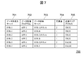
- the data replication table 700 is a table for managing a data replication destination.
- the data transmission / reception program 303 described above transmits or replicates data, it refers to the data replication table 700 and determines the data transmission destination or replication destination. Processing at the time of data replication will be described later.
- the data replication table 700 includes a data generation server column 701, a data processing program column 702, a data storage server column 703, a redundancy column 704, and a proximity area access column 705.
- the data generation source server column 701 an ID indicating a server that generates processing data is stored.
- the data processing program column 702 stores an ID indicating a data processing program 302 that operates on the data generation source server and generates machining data.
- an ID indicating a server that stores processing data generated by the data generation source server is stored.
- a plurality of IDs are stored in a comma-separated manner such as “SVR-1, SVR-A”.
- SVR-1, SVR-A comma-separated manner
- the redundancy column 704 is a value that defines how many copies of the machining data, including the original machining data, are required in the information processing system.
- the redundancy is 1, the processed data is deleted from the transmission source server after the data transmission is completed.
- the redundancy is 2 or more, the data is stored in the server that generates the data and the other servers. However, if there are a number of duplicates of data other than the data source server that satisfy the redundancy, the data source Processing data is deleted from the server.
- the initial value of redundancy is set to 2, but may be changed according to the quality required for the service using the data processing program, the server for storing data, and the storage quality.
- the proximity area access column 705 is a value indicating whether the data storage server can be changed to a server in the area connected by the user when the server is changed to a server suitable for the use location of the user, and TRUE or FALSE is set.
- the processed data generated by the data processing program “APP-1” on the server “SVR-1” is stored in the server “SVR-1” as it is, and is also copied to “SVR-A”. You can see that Further, the processed data generated by “APP-2” on the server “SVR-1” is copied to the server “SVR-B” and then sent from the server “SVR-1” that is the generation server at some timing. You can see that it has been deleted.
- the replication destination is defined for the data processing program, not the machining data.
- sensor data may be generated and stored in real time, and new files may be frequently generated.
- a processing data replication destination is defined for each data processing program for the purpose of facilitating table maintenance.
- the data generation source server and the storage destination server may be managed in units of data.
- the service program table 800 is an example of a table indicating the relationship between the sensors 102 used by the service program 304 and the data processing program 302 that processes the data acquired from the sensors 102 and generates the processed data 306.
- the service program table 800 is defined when the system administrator registers a service in the information processing system, and is stored as part of the management data 133 included in the overall management server 107.
- the service program table 800 includes a service program column 801, a sensor column 802, a data processing program column 803, and a proximity area access column 804.
- an ID for identifying the service program 304 is stored in the service program column 801.
- the sensor column 802 stores a value indicating one or more areas 101 in which sensors used by the service program 304 are arranged, or a value indicating one or more sensors 102.
- an area is designated, it is equivalent to setting all sensors related to the area defined in the server table 400.
- a value concatenated with commas is set.
- the data processing program column 803 stores an ID indicating the data processing program 302 that processes sensor data used by the service program.
- the proximity area access column 804 is a value indicating whether the service program connected by the user can use the area connected by the user or the processing data copied in the proximity area, and TRUE or FALSE indicates Is set.
- the service accesses the data stored in the data generation source server. This attribute is used to rank service quality, such as services that can be accessed at high speed by accessing data in the vicinity of the user, even if the service uses the same data, and services that do not.
- the service usage status table 900 is an example of a table that manages the relationship between the area 101 where the user connects to the service program 304 and the usage scale of the service program.
- service usage status table 900 records are automatically generated for the combination of the service program 304 operating on the system and the area defined in the server table 400, and the service management program 332 every time the user uses the service program. Usage status is updated.
- the service usage status table 900 includes a service program column 901, a user area column 902, a service user number column 903, and a threshold column 904.
- the service program column 901 stores the ID of the service program 304 used by the user.
- the user area column 902 stores an area where the user connects to the service. For example, when a user at a point included in “Yokohama1” uses a service from a mobile terminal, “Yokohama1” is stored in the “user area”.
- the service user number column 903 stores the number of users using the service.
- the number of users is the number of users in a certain period, for example, the number of users per day.
- the threshold value column 904 is a threshold value for changing a server that executes a service program and a data copy destination, and stores a value for the number of service users. For example, when the threshold value is “10000” and an area where the service users per day exceed 10,000, the service is executed in that area, and the data replication destination is switched to that area.
- the service program “SP-1” has 12000 accesses from the user area “Tokyo1” area, 1000 accesses from the “Yokohama1” area, and no access from the “Fukuoka1” area. I understand that.
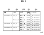
- FIG. 10 is an example of the data arrangement list 1000 generated by the service management program 1504.
- the data arrangement list 100 illustrated in FIG. 10 when the sensor 102 is a monitoring camera, the acquisition time of data acquired by the monitoring camera, the data storage destination, and the like are stored.
- the data arrangement list 1000 includes a time column 1001, an area column 1002, a data column 1003, a storage destination server column 1004, and a data bus column 1005.
- the time column 1001 stores the time when the data was acquired.
- the area column 1002 stores the area from which the data was acquired and is sorted based on the start time column 604 of the machining data management table 600.
- the data column 1003 stores the contents of the data, and the value in the sensor column 602 of the machining data management table 600 is converted into a name that can be easily understood by the user.
- the storage destination server column 1004 stores data storage destination information.
- the data path column 1005 stores the data path name.
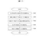
- the data collection program 301 of the server 103 receives information from the sensor 102 connected to the server (S1101). Then, the data collection program 301 stores the data (raw data 305) received in step S1101 in the storage 203 (S1102).
- the server 103 calls the data processing program 302, reads the raw data 305, processes it into data suitable for the service (S1103), and stores the processed data 306 in the storage 203 (S1104).
- the server 103 executes the data transmission / reception program 303, determines whether or not the data transmission / reception program 303 copies the processed data 306 to the other server 103, and when it is necessary to copy, the processed data 306 is transferred to the other server. (S1105).
- the data collected from the sensor 102 is processed into data suitable for the service on the server 103 side close to the sensor 102, and the processed data is stored in the server 103 suitable for use by the user. .
- FIG. 12 is a sequence diagram showing the processing until the data collected from the sensor 102 is processed and stored in the server 103.
- the sensor 102 transmits its own sensor ID and sensor data (raw data 1) to the data collection program 301 operating on the server 103 (S1211).
- the data collection program 301 that has received the data from the sensor 102 stores the data in the storage 203 (S1212), and returns a reception completion to the sensor 102 (S1213). If the sensor 102 does not need to consider the transmission / reception result, step S1213 may be omitted.
- the data collection program 301 storing the data in step S1211 transmits a data storage completion notification to the configuration management program 331 operating on the overall management server 107 that the data has been stored (S1214).
- the data storage completion notification transmitted in step S1214 includes the server ID of the server 103, the data path, the ID of the sensor 102 that transmitted the sensor data, and the start time and end time of the sensor data as parameters.
- step S1214 the configuration management program 331 that has received the data storage completion notification registers the received data as row data of the raw data management table 500. If there is a row in the raw data management table 500 that has the same sensor 102 and raw data values as the already received data, the row is updated.
- data update processing is processing that occurs in the case of an application that overwrites an old file every three months, for example.
- the configuration management program 331 updates the raw data management table 500
- the configuration management program 331 next refers to the sensor column 802 of the service program table 800, and acquires the value of the data processing program column 803 in the row including the acquired sensor ID. Then, the data is returned to the data collection program 1202 (S1215).
- the data collection program 301 requests the data processing program 302 corresponding to the acquired ID of the data processing program to process the raw data 1 (S1216).
- the data processing program 302 processes the data and stores it in the storage 203 (S1217), and then returns a completion notification and a processed data path as a return value (S1218).
- the data collection program 301 that received the completion notification in step S1218 transmits a processing data storage notification to the configuration management program 331 (S1219).
- the processed data storage notification includes the ID of the data processing program that processed the data, the sensor ID of the transmission source of the raw data 1, the path of the processed data, the start time and the end time of the raw data 1, and the server ID of the own server. Is included as a parameter.
- step S1219 the configuration management program 331 that has received the machining data storage notification adds the acquired parameter to the machining data management table 600 and notifies the completion (S1220).
- step S1220 the data collection program 301 that receives the completion notification calls a data replication process to replicate the data to another server (S1221). If there are a plurality of data processing programs for processing the raw data 1 in the return value of step S1215, the processing from step S1216 to step S1221 is repeated a plurality of times.
- the server 103 to which the sensor 102 is connected stores the raw data 305 and the processed data 306 collected from the sensor 102 in the storage 203 of its own server, and notifies the overall management server 107 of the result. Complete.
- FIG. 13 is a sequence diagram showing a process in which the data collection program 301 replicates the machining data 306 stored in its own server to another server.
- the data collection program 301 performs data replication with respect to the configuration management program 331 on the overall management server 107 using the server ID of the server itself, the ID of the data processing program that processed the processing data, and the data path of the processing data as parameters. A request is made (S1311).
- the configuration management program 331 refers to the record in which the server ID and the data processing program match in the data replication table 700, acquires the value of the data storage server 703, and notifies it as a replication destination (replication destination list) (S1313).
- the data transmission / reception program 303 notifies the completion of the process by skipping step S1314 and subsequent steps when a server other than the server itself is not included in the replication destination list (S1322). On the other hand, when a server other than the local server is included in the replication destination list, the processed data is transmitted to the data transmission / reception program 303 operating in the replication destination server acquired in S1313 (S1314).
- the data transmission / reception program 303 that has received the data in step S1314 stores the data in the storage of its own server (S1315), and notifies the data transmission / reception program 303 of the data transmission source server that the data storage is complete (S1316).
- the data transmission / reception program 303 confirms that the data replication has been completed with respect to the configuration management program 331 by using the copied processing data path and the ID of the replication destination server as parameters. Is notified (S1317).
- step S1317 the configuration management program 331 that has received the notification of completion of replication sets the acquired server ID as the value in the storage destination server column 606 for the record that matches the processing data column 603 of the processing data management table 600. Add and update values.
- the completion is notified to the data transmission / reception program 303 of the data generation source server (S1318). For example, if the value in the storage destination server column 606 of the processed data management table 600 is “SVR-1” and “SVR-A” is sent as the replication destination server ID, the value in the storage destination server column 606 is The values are updated to “SVR-1, SVR-A”.
- the local server is not included in the replication destination list acquired in step S1316, it means that there are a number of replicas of data satisfying the redundancy other than the local server.
- the target machining data is deleted from the server (S1319). Then, the configuration management program 1304 is notified of the deletion completion using the machining data path and the server ID of the server as parameters (S1320).
- step S1320 the configuration management program 331 that has received the notification of the completion of deletion selects a record with a matching path in the machining data column 603 from the machining data management table 600, and the server ID specified from the value in the storage destination server column 606. Delete the value of. For example, when the value “SVR-1, SVR-A” is stored in the storage destination server column 606 and the server ID “SVR-1” is specified as the parameter of the deletion completion notification, “SVR” Only the value -A "will be stored.
- the data collected from the sensor 102 is sequentially processed by the data processing program 302 on each server 103, and a copy is made on another server.
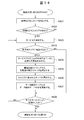
- the replication destination switching process shown in FIG. 14 is a process executed periodically (for example, once every hour) in the overall management server 107.
- the service management program 332 refers to the service usage status table 900 and extracts a record in which the value in the service user number column 903 exceeds the value in the threshold value column 904 (S1401).
- the service management program 332 determines whether there is a record exceeding the threshold in the extraction process of step S1401 (S1402).
- step S1402 If it is determined in step S1402 that there is no record that exceeds the threshold, the service management program 332 ends the process. On the other hand, if it is determined in step S1402 that there is a record exceeding the threshold, the service management program 332 selects one service program from the service programs included in the record (S1403). At this time, a plurality of records, that is, a record having a user area column 902 in which different values are stored may hit a plurality.
- the service management program 332 determines whether or not the processing data used by the selected service program is copied to the area where the user uses the service (S1410). Specifically, the service management program 332 compares the value of the service program selected in step S1403 with the service program column 801 of the service program table 800, and selects a record that matches the value. Then, the service management program 332 confirms whether the value of the proximity area access field 804 corresponding to the selected service program is TRUE or FALSE.
- step S1410 if the value of the proximity area access field 804 is TRUE, that is, if it is determined that the data needs to be duplicated, the process proceeds to steps after step S1404. On the other hand, if the value of the proximity area access field 804 is FALSE, that is, if it is determined not to copy the data, the data of the service program does not need to be copied to the area near the user. Moves to the next service program without updating.
- the service management program 332 obtains the redundancy necessary for the machining data used by the service program for the selected service program (S1404). Specifically, a record in which the value of the service program column 801 of the service program table 800 matches the value of the service program selected in step S1403 is selected, and the value of the data processing program column 803 of that record is acquired. Then, by referring to the data replication table 700, selecting a record in which the value of the acquired data processing program matches the value of the data processing program column 702 of the data replication table 700, and acquiring the value of the redundancy column 704, Determine redundancy. The record acquired at this time is referred to as a record A. When multiple redundancy levels are acquired, the maximum redundancy level is used.
- the service management program 332 obtains the redundancy in step S1404, and then, for the record in the service usage status table 900 selected in S1403, the areas corresponding to the number of redundancy in order from the area having the largest value in the service user number column 903 Is selected (S1405).
- the service management program 332 refers to the server table 400 and selects one server from each area. If the number of areas selected in step S1405 is less than the redundancy level, servers that are insufficient in redundancy level are further selected from any area (S1406).
- the server set selected here is referred to as a server set A.
- the service management program 332 updates the value of the data storage server column 703 with the value of the server set A for the record A of the data replication table 700 acquired in step S1404 (S1407). That is, a storage server that stores processing data used by the service program is set as a server included in the server set A. At this time, if the number of servers included in the server set A does not satisfy the redundancy, the insufficient servers are selected from the values of the data storage server 703 before the update and registered in addition to the server set A.
- the value of the data generation source 701 is included in the data storage server 703, that server is used with priority. This is because when the redundancy is satisfied, the network load can be suppressed when the data generation source server is included in the data storage destination. If the redundancy cannot still be satisfied, select the insufficient servers from the area including the data generation source server and register them. Similarly, since replication occurs in the data generation source area, there is an effect of minimizing the influence on the network load.
- the service management program 332 determines whether the processes from S1403 to S1407 have been executed for all the services included in the record selected in step S1401 (S1408). If it is determined in step S1408 that processing has been executed for all services, this processing ends. On the other hand, if it is determined in step S1408 that there is an unprocessed service, an unprocessed service is selected and the processing from step S1403 to step S1407 is repeated.
- the replica of the processed data is arranged on the server in the area where the user is present according to the number of users, so that the data redundancy is increased. While maintaining, the performance when the user accesses the machining data through the service program can be improved. In addition, it is possible to reduce the network load in order to prevent unnecessary duplication from occurring in an area where there is no user.
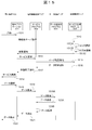
- the terminal application 321 of the terminal device 106 communicates with the service management program 332 to determine the connection destination server 103 and connects to the connection destination service program 304 to provide the service. Further, the service program 304 acquires the arrangement of data necessary for the service from the service management program 332, acquires and returns data in response to a request from the terminal device 106. It is assumed that the terminal application 321 and the service program 304 are arranged in advance on each device.
- the terminal application 321 uses the service ID of the service connected to the location information of the terminal application 321 as a parameter to the service management program 332 as a parameter.
- the location information is geographical location information by GPS provided in the terminal device 106, location information that can be specified from the IP address of the terminal device, information determined by a frequently used area designated by the user, etc. It is.
- the service management program 332 that has received the request from the terminal application 321 determines the optimum area “area” from the area 1 column 403 and the area 2 column 404 registered in the server table 400 based on the location information specified by the input parameter. A ”is selected (S1513A).
- a method for selecting the area A in the case where the position information acquired from the terminal application 321 is GPS information, a method for selecting the area including the GPS position information by defining the geographical range of each area in advance. There is. Further, when the position information is an IP address, a terminal device connected from a specific area is assigned a specific range of IP addresses in advance, and the IP address range and the area are associated with each other. Thus, a method of selecting an area may be used.
- the area registered in the server table 400 is disclosed to the user so that the user can designate the value of the area as an area where the service is frequently used, so that the area value can be directly transmitted as position information. It may be the method that comes. Through these processes, the service management program 332 selects an area corresponding to the transmitted position information.
- the value in the service user number column 903 of the service usage status table 900 corresponding to the value is increased by 1 (S1513B).
- the number of users in the area where the user is connected to the service is counted.
- the service management program 332 lists servers having values in the area 1 column 403 and area 2 column 404 of the server table 400 as the area selected in step S1513A, and selects an arbitrary server from the list. The selected result is returned as the connection destination of the terminal application 321 (S1513C).
- the terminal application 321 that has acquired the connection destination server in step S1513C requests a service from the service program 304 of the server 103 (S1519).
- Access to the service is an access point suitable for the form of providing the service program.
- the service point may be accessed by specifying a URL, or may be accessed by a host name and a port number.
- step S1519 the service program 304 that has received the service request requests the service management program 332 to acquire data arrangement using the server ID of the server as a parameter (S1515).
- step S1519 the service management program 332 that has received the data arrangement acquisition request refers to the server table 400, the processing data management table 600, and the service program table 800 to determine a data arrangement destination suitable for the service program 304.
- the sensor 102 and the data processing program 302 corresponding to the service program 304 are acquired from the sensor column 802 and the data processing program column 803 of the service program table 800. Also, records that match or are included in the data processing program column 601 and the sensor column 602 from the machining data management table 600 are listed. As a result, a list of processing data used by the service program 304 and a server pair storing the data is generated.
- the service program 304 When the service program 304 is not permitted to access the proximity area, specifically, when the value of the proximity area access field 804 of the service program table 800 is FALSE, the value of the storage destination server field 606 when the server is selected as described above. If the server in the source server column 607 is included in the list, that server is selected. As a result, it is possible to provide a quality of service such as a high-quality service that can access data close to the position of the service program 304 and a low-quality service that is not.
- a quality of service such as a high-quality service that can access data close to the position of the service program 304 and a low-quality service that is not.
- the service management program 332 generates a data arrangement list for the service program 304 and returns it as a result (S1516).
- the service program 304 that has received the data arrangement in step S1516 notifies that the service can be provided (S1517), and the terminal application 321 displays a service screen to the user (S1518).
- the service screen presented to the user in step S1518 is the list shown in FIG.
- This list displays what data can be referenced in each area for each time.
- the user is directly aware of the time 1001, the area 1002, and the data 1003.
- the storage destination server 1004 and the data path 1005 are internal parameters and the user is not directly aware of them.
- Time 1001 and area 1002 are sorted and displayed based on the start time column 604 of the machining data management table 600. Further, the data 1003 is displayed by converting the value in the sensor column 602 of the machining data management table 600 into a name that can be easily understood by the user.
- the service program 304 requests the requested data from the data transmission / reception program 1503 of the server storing the data based on the data arrangement list acquired in step S1516 (S1519A), and acquires the data ( S1520A).
- the data storage destination is the local server
- the data is acquired from the storage 203 of the local server (S1519B).
- the service program 304 When the service program 304 acquires data, the service program 304 transmits the data to the terminal application 321 (S1521), and the terminal application 321 presents the transmitted data to the user (S1522).
- each of the processes described in FIG. 11 to FIG. 15 operates, so that the terminal application is connected to the service program that operates on the server in the area near the user and Will behave as if they are replicated.
- the processing data of the service used by the user is arranged in the area near the user, and the user can access the data smoothly.
- each server behaves so as to replicate processed data in the vicinity of the user, and by dynamically managing the arrangement of data accessed by the service program on the system side, The convenience of the user is improved because the data can be used without making the user directly aware of the location of the processed data.
- the terminal application 321 detects a communication failure (S1613), it requests acquisition of an alternative server using the server ID of the server connected so far as a parameter (S1614).
- the service management program 1604 that has received the substitute server acquisition request selects a server other than the server ID acquired as a parameter and notifies it as an alternative server (S1615).
- the alternative server selected in step S1615 may be a server in an area including a server in which the terminal application 321 failed to communicate, or a server in which a copy of data requested by the terminal application 321 is stored.
- the service program 304 since the service program 304 operates in the area near the user, it is possible to maintain high service response performance.
- the service quality is higher than usual. However, the amount of data flowing through the network can be reduced.
- step S1615 when the terminal application 321 receives the alternative server, it connects to the service program 304 operating on the alternative server (S1616).
- step S1616 the service program 1603 that has received the connection request from the terminal application 321 requests the service management program 332 to acquire data arrangement (S1617).
- step S1617 the service management program 332 that has received the data allocation acquisition request from the service program 304 of the alternative server notifies the service program 304 of the result (S1618). Since S1617 to S1618 are the same processes as S1515 and S1516 of FIG. 15, detailed description thereof will be omitted.
- the service program 304 of the alternative server receives the data arrangement in step S1618, acquires data corresponding to the data arrangement (S1619), and transmits the data to the terminal application 321 (S1620). Then, the terminal application 321 that has received the data in step S1620 displays the received data on the display screen (1621).
- failures include not only hardware server failures and network failures, but also response degradation due to concentration of access, and response degradation due to lack of resources such as server CPU and memory.
- FIG. 17 is an example of a management screen for defining the server table 400 and the area table 410.
- the server addition screen 1701 is a screen for the system administrator to register the association of the server, the sensor, and the area to which the server belongs.
- the server input field 1702 is a field for inputting an ID for identifying a server.
- the sensor input field 1703 is a field for inputting a sensor for storing data in the server input in the server input field 1702. If there are multiple sensors, enter them separated by commas.
- the area 1 input field 1704 is a first field for inputting an area to which the server belongs.
- the value to be input is a value indicating an area defined on an area addition screen 1721 described later.
- An area 2 input field 1705 is a second field for inputting an area to which the server belongs.
- the value to be input is a value indicating an area defined on an area addition screen 1721 described later.
- the service program input field 1706 is a field for inputting a value for identifying a service program installed in the server.
- the value to be input is a value indicating a service program defined on a service addition screen 1801 described later.
- the execute button 1707 is a button for registering a server having a value input in each input field in the system.
- the value input in each input field is transmitted to the configuration management program 331 on the overall management server 107, and the management data 333 is updated.
- the configuration management program 331 stores the value input in the server input field 1702 in the server column 401 and the value input in the sensor input field 703 in the sensor column 402 for the server table 400.
- the value input in the area 1 input field 1704 is stored in the area 1 column 403, the value input in the area 2 input field 1705 is stored in the area 2 column 404, and the value input in the service program input field 1706 is stored.
- the area addition screen 1721 is a screen for the system administrator to define an area to which a server, a sensor, a terminal device, and the like belong.
- the area input field 1722 is a field for inputting an area name.
- a longitude / latitude input field 1723, an IP address input field 1724, and an access point 1725 are input fields for defining position information for specifying an area. At least one input field must be entered.
- the longitude / latitude input field 1723 is a field for inputting a value indicating the range of longitude / latitude of the area.
- the range specifies the northwest and southeast points of the rectangular area, such as x1, y1-x2, y2.
- GPS information is sent from the terminal device, the device located in this rectangular area is interpreted on the system side as belonging to the area defined in the area input field 1722.
- the IP address input field 1724 is a field for inputting an IP address assigned to a device belonging to the area.
- the system side interprets that the device having this IP address belongs to the area defined in the area input field 1722.
- the access point input field 1725 is a field for inputting a value for identifying an access point through which the terminal device accesses the service program.
- the system interprets that the device belongs to the area defined in the area input field 1722.
- Execute button 1726 is a button for registering an area having a value input in each input field in the system. When the execute button 1726 is pressed, the value input in each input field is transmitted to the configuration management program 331 on the overall management server 107 and the management data 333 is updated.
- the configuration management program 331 stores the value input in the area input field 1722 in the area column 411 and stores the value input in the longitude / latitude input field 1723 in the longitude / latitude column for the area table 410.
- the value input in the IP address input field 1724 is stored in the IP address column 413, and the value input in the access point input field 1724 is stored in the access point column 414.
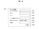
- FIG. 18 shows an example of a service addition screen 1801 in which the system administrator defines the service program configuration and the service program requirements.
- the service program input field 1802 is a field for inputting an ID for identifying a service program.
- the sensor input field 1803 is an input field for designating a sensor used by the service.
- the area name of the area registered on the area addition screen 1721 can be input.
- the area name is input, it means that all the sensors included in the area are specified.
- the server input field 1804 is an input field for designating a server that performs processing of sensor data used by the service program.
- the data processing program input field 1805 is an input field for designating a data processing program for processing sensor data.
- the proximity area access radio button 1806 is a radio button for designating whether access from the proximity area is valid or invalid for the service.
- the redundancy level input field 1807 is a value for designating the redundancy level of machining data used by the service program.
- the execution button 1808 is a button for registering in the system a service composed of values input in the respective input fields.
- the value input in each input field is transmitted to the service management program 332 on the overall management server 107 and the management data 333 is updated.
- the service management program 332 stores the value input in the service program input field 1802 in the service program column 801 and stores the value input in the sensor input field 1803 in the sensor column 802 with respect to the service program table 800.
- the value input to the data processing program 1805 is stored in the data processing program column 803. If the proximity area access radio button 1735 is valid, TRUE is indicated, and if the proximity area access radio button 1735 is invalid, the value FALSE is indicated. To store.
- the service management program 332 stores, in the data replication table 700, the value input in the server input field 1804 in the data generation server column 701, and the value input in the data processing program 1805 as the data processing program column.
- the value input in the redundancy input field 1807 is stored in the redundancy column 704.
- the value of the data generation source server column 701 and the server ID of another server included in the area to which the server identified by the value belongs are added by the amount of redundancy.
- Register in the storage server column 703. For example, when the redundancy is “2”, the data generation server is “SVR-1”, and the area “EastJapan” to which the server “SVR-1” belongs includes “SVR-2”, “SVR-1” , SVR-2 ”is set.
- the present invention is not limited to the above-described embodiment as it is, and can be embodied by modifying the constituent elements without departing from the scope of the invention in the implementation stage.
- various inventions can be formed by appropriately combining a plurality of constituent elements disclosed in the above embodiments. For example, some components may be deleted from all the components shown in the embodiment. Furthermore, constituent elements over different embodiments may be appropriately combined.
Landscapes
- Engineering & Computer Science (AREA)
- Computer Networks & Wireless Communication (AREA)
- Signal Processing (AREA)
- Health & Medical Sciences (AREA)
- Computing Systems (AREA)
- General Health & Medical Sciences (AREA)
- Medical Informatics (AREA)
- Information Transfer Between Computers (AREA)
Abstract
【課題】複数のサーバが分散配置されている場合に、ユーザの位置するエリアを考慮してデータを配信する。 【解決手段】一つ以上のサーバ、一つ以上のセンサが分散配置されネットワークを介して接続されている情報処理システムであって、前記サーバは、前記センサから収集したセンサデータを格納する記憶部と、ユーザ端末からの要求に応じて、前記センサデータをもとに所定のサービスを提供するサービスプログラムの実行を制御する制御部と、を備え、前記制御部は、前記要求のあったユーザ端末の近傍のサーバに前記センサデータを送信し、該サーバに前記ユーザ端末を接続させて、該サーバ上で前記サービスプログラムを実行させる。
Description
本発明は、情報処理システム及びデータ管理方法に関し、分散配置される複数のサーバを利用して利用者にサービス応答性能の高いサービスを提供する情報処理システム、データ管理方法及びプログラムに適用して好適なるものである。
広域のコンピュータネットワークに接続された情報処理システムでは、中央のデータセンタに配置された情報処理装置の処理機能を使用して、端末装置に対して処理結果を送信する形態が一般的になっている。特に、クラウドコンピューティングと呼ばれる情報処理システムの利用形態では、データセンタ上のサーバやストレージなどの情報処理装置へ処理を集中させ、利用者がデータセンタとネットワークで接続された外部計算機から情報処理装置を利用するのが一般的である。クラウドコンピューティングにより、データセンタ上へ情報処理を集中させることにより、システム構築コストやランニングコストを低減させることができる。
上記したように、クラウドコンピューティングでは、データセンタ上の情報処理装置に処理を集中させている。このため、システムの利用者が増加し、多数の端末から、データセンタ上の情報処理装置に対して情報処理の要求があると、情報処理要求への返答の品質が低下する。ここで、情報処理要求への返答の品質とは、いわゆるデータのスループットや応答時間などを意味する。
この要求に対する返答の品質を保持するためには、接続回線の増強が必要となる。データセンタ上にて情報処理装置を提供する企業としては、この回線増強のコスト増が事業運営での課題となる。これまで、利用者の端末の処理性能が高くないか、または、利用者の端末が基幹ネットワークへ接続するための無線アクセス網のアクセススピードが遅いため、要求に対する品質が大きな問題とならなかった。しかし、近年、処理時間に対する品質の要求が高まっており、さらなる回線品質の確保が課題となっている。
このため、データセンタ事業者や、データセンタ事業者から設備を借り入れ、ホスティング事業に利用したり、自社利用したりしている事業者は、広域のネットワーク上に分散して配置された情報処理装置を用いて負荷分散を図っている。具体的に、事業者は、分散された複数の情報処理装置上に、アプリケーションやデータの複製を配布し、中央のデータセンタの情報処理装置の利用頻度を下げるなどして負荷分散措置を取っている。これにより、情報処理要求への返答の品質を維持している。このような負荷分散の技術として、例えば、特許文献1に開示されているコンテンツデリバリネットワーク(CDN)が挙げられる。
特許文献1に記載されているCDN技術では、主に音楽や動画といったデジタルコンテンツのようなデータを、ユーザ近傍に配布することを目的としている。CDN技術では、コンテンツを利用するユーザに近いネットワーク上のさまざまな場所にコンテンツの配布拠点(サーバ)を用意している。そして、利用者の位置に応じて適切な配布拠点へのアクセスを指示することにより、大量のコンテンツをスムーズに利用者に配信できるようにしている。このように、配布対象のデータを中央のデータセンタ、または、オリジナルコンテンツを所有するサーバから配信することで、ネットワーク負荷を減少させている。
ここで、複数のサーバが分散配置され、各サーバには種々のデータを収集するための一つ以上のセンサが接続されている情報処理システムに上記したCDN技術を適用することが考えられる。上記したCDN技術では、地域毎やユーザ毎に利用されるデータに差がある場合でも、分散している各サーバに一律にデータを配布(キャッシュ)してしまう。したがって、サーバが分散配置された情報処理システムにCDN技術を適用すると、利用者がデータを参照するときのアクセス性能が高くなる一方で、情報処理システム全体としては、利用されないエリアへのコンテンツ配布(データ送信)が発生してしまい、サーバ容量の無駄な消費や分散システム全域に対するデータ送信に伴うネットワークの負荷が増大したり応答性能が低下したりしてしまうという問題があった。
本発明は以上の点を考慮してなされたもので、複数のサーバが分散配置されている場合に、ユーザの位置するエリアを考慮してデータを配信する情報処理システム、データ管理方法及びプログラムを提案しようとするものである。
かかる課題を解決するために本発明においては、一つ以上のサーバ、一つ以上のセンサが分散配置されネットワークを介して接続されている情報処理システムであって、前記サーバは、前記センサから収集したセンサデータを格納する記憶部と、ユーザ端末からの要求に応じて、前記センサデータをもとに所定のサービスを提供するサービスプログラムの実行を制御する制御部と、を備え、前記制御部は、前記要求のあったユーザ端末の近傍のサーバに前記センサデータを送信し、該サーバに前記ユーザ端末を接続させて、該サーバ上で前記サービスプログラムを実行させることを特徴とする、情報処理システムが提供される。
かかる構成によれば、広域に複数のサーバやセンサが分散配置され、利用者がそれらのデータを利用する情報処理システムにおいて、ユーザが利用するユーザ端末の近傍のサーバ上でユーザが要求するサービスに対応するサービスプログラムが実行される。これにより、ネットワークやサーバのリソースの無駄を抑えつつ、ユーザの利便性を考慮してセンサ情報を処理したり配布したりすることが可能となる。
本発明によれば、ネットワークやサーバのリソースの無駄を低減しつつ、ユーザの利便性を向上させることができる。
以下図面について、本発明の一実施の形態を詳述する。
なお、以後の説明では「aaaテーブル」、「aaaリスト」、「aaaDB」、「aaaキュー」等の表現にて本発明の情報を説明するが、これら情報は必ずしもテーブル、リスト、DB、キュー、等のデータ構造以外で表現されていてもよい。そのため、データ構造に依存しないことを示すために「aaaテーブル」、「aaaリスト」、「aaaDB」、「aaaキュー」等について「aaa情報」と呼ぶことがある。さらに、各情報の内容を説明する際に、「識別情報」、「識別子」、「名」、「名前」、「ID」という表現を用いるが、これらについてはお互いに置換が可能である。
以後の説明では「プログラム」を主語として説明を行う場合があるが、プログラムはプロセッサによって実行されることで定められた処理をメモリ及び通信ポート(通信制御デバイス)を用いながら行うため、プロセッサを主語とした説明としてもよい。また、プログラムを主語として開示された処理は管理サーバ等の計算機、情報処理装置が行う処理としてもよい。また、プログラムの一部または全ては専用ハードウェアによって実現されてもよい。
また、各種プログラムはプログラム配布サーバや、計算機が読み取り可能な記憶メディアによって各計算機にインストールされてもよい。
(1)本実施の形態の概要
まず、本実施の形態の概要について説明する。以下では、複数のサーバがネットワーク上に分散配置されている場合に、利用者がサーバ上のデータを利用する情報処理システムについて説明する。
まず、本実施の形態の概要について説明する。以下では、複数のサーバがネットワーク上に分散配置されている場合に、利用者がサーバ上のデータを利用する情報処理システムについて説明する。
上記したように、複数のサーバが分散配置され、各サーバには種々のデータを収集するための一つ以上のセンサが接続されている情報システムにCDN技術を適用した場合には、分散している各サーバに一律にデータを配布するため、利用されないエリアへのコンテンツ配布が発生してしまう。これにより、サーバ容量の無駄な消費や分散システム全域に対するデータ送信に伴うネットワークの負荷が増大したり応答性能が低下したりする。
また、一度アップロードされたら変更されない音楽や動画などの静的なコンテンツではない場合には、予めコンテンツを配布しておくことができない。静的なコンテンツではない情報とは、例えば、監視カメラのようなセンサから毎秒新しいデータが収集・蓄積されるシステムなどを例示できる。また、上記したように、一部の利用者のみがそのセンサデータを利用する場合には、利用者が利用しないサーバにデータを配布してデータ転送に無駄なコストが発生してしまう。
また、ネットワーク上に分散された各サーバに接続されているセンサから収集したデータを扱うサービスでは、それらのデータを単にサーバにキャッシュするだけでは利用者が所望するサービスを提供することができない。例えば、監視カメラの映像をほぼリアルタイムで遠隔地から確認することができるサービスを提供する場合には、単に、サーバにデータがキャッシュされているだけでは、利用者に必要な情報を提供することができない。このようなサービスでは、利用者に、監視カメラの映像データがどこのセンサでいつ収集されたデータかというデータの位置や時系列の情報も提供する必要がある。したがって、単にデータをユーザ近傍のサーバにキャッシュするだけでは、ユーザが必要とする情報を提供することができず、サービス全体としては、ユーザの利便性が改善されないという問題があった。これは、サーバ及びセンサが、広域に多量に分散して配置されればされるほど顕著となる。
そこで、本実施の形態では、広域に複数のサーバやセンサが分散配置され、利用者がそれらのデータを利用する情報処理システムにおいて、ネットワークやサーバのリソースの無駄を抑えつつ、ユーザの利便性を考慮してセンサ情報を処理したり配布したりすることを可能としている。
(2)情報処理システムの概要
図1に、本実施の形態にかかる情報処理システムの構成を示す。本実施形態の情報処理システムは、エリアA、エリアB、エリアC、エリアD及びエリアEの複数のエリア101から構成される。各エリアは、サーバ103、センサ102及びサーバ103が提供するサービスを利用する端末機器106から構成されている。また、各種機器はネットワーク104を介して接続されている。
図1に、本実施の形態にかかる情報処理システムの構成を示す。本実施形態の情報処理システムは、エリアA、エリアB、エリアC、エリアD及びエリアEの複数のエリア101から構成される。各エリアは、サーバ103、センサ102及びサーバ103が提供するサービスを利用する端末機器106から構成されている。また、各種機器はネットワーク104を介して接続されている。
エリア101には、センサ102、サーバ103及び管理サーバ105が設置される。ここで、エリアとは、町、市、県、地方、国などの地理的な区分や、データセンタやサーバルーム、社内の各建物のようなあらかじめ定められた特定の領域である。エリア101は、各エリアが重複してもよい。例えば、エリアAとエリアBを含むエリアABを1つのエリアとして定義してもよい。
センサ102は、動画、静止画、音声、温度など種々の情報を計測、収集するための機器であり、ユーザに提供するサービスに応じたセンサが配置される。一つのサービスが複数のセンサ102を使用してもよい。センサ102は、ネットワーク104を介してサーバ103と接続されており、センサ102が収集したデータはサーバ103が有するストレージに格納される。
サーバ103は、センサ情報の収集及び蓄積と、利用者に対しサービスを提供するための情報処理を行うアプリケーションサーバである。サーバ103は、センサ102の情報の収集と蓄積、センサ102から収集した情報の加工、加工したデータを利用するサービスプログラムの実行、他サーバと連携しサーバ間でデータの送信、複製、参照などの各処理を行う。また、サーバ103は、複数のセンサ102から情報を収集する場合や、複数の異なる種類のセンサ102からの情報を収集する場合もある。サーバ103の構成については後で詳細に説明する。
ネットワーク104は、センサ102、サーバ103、管理サーバ105、端末機器106を接続し、各コンポーネント間でデータを送受信するためのネットワークである。ネットワーク104は、LAN、WAN、無線LANなどを例示できるが、データを送受信可能ならば他の形態でもよい。
管理サーバ105は、エリア内の各機器を監視、制御するためのサーバである。また、全体管理サーバ107からの要求を受け、サービスプログラムの配置や起動、他のサーバとのデータの送信や複製を実行する。
全体管理サーバ107は、情報処理システム全体を管理するためのサーバである。全体管理サーバ107は、情報処理システム内で動作するサービスの状態管理や、端末機器106のサービス利用状況の管理、サーバ103に蓄積されている各データの管理などを行う。
端末機器106は、ユーザがサービスに接続しサービスを利用するために使用するPC(Personal Computer)やスマート端末である。端末機器106は、有線または無線ネットワーク104を介してサーバ103、管理サーバ105及び全体管理サーバ107と接続される。図1では、端末機器106は各エリア101内に図示しているが、端末機器106が携帯端末の場合、端末機器106の利用者が移動することにより端末機器106も合わせて移動し、前回サービスを利用したエリアとは異なるエリアからサーバに接続することもある。
また、各エリア101には、センサ102、サーバ103、管理サーバ105及び端末機器106の各機器が含まれるが、情報処理システムの形態によっては、サービスのみを提供し、センサ102が存在しないエリアや、端末機器106が存在しないエリアがあってもよい。
図2に、サーバ103を実現する計算機のハードウェア構成を示す。図2に示すように、サーバ103は、CPU201、メモリ202、ストレージ203、入出力装置204及びネットワークインタフェース205から構成される。
CPU201は、演算処理装置および制御装置として機能し、各種プログラムに従ってサーバ103内の動作全般を制御する。また、CPU201は、マイクロプロセッサであってもよい。
メモリ202は、CPU201の実行において使用するプログラムや、その実行において適宜変化するパラメータ等を一次記憶する。ストレージ203はプログラム及びプログラムが利用するデータを格納する装置であり、HDDやSSDなどを例示できる。
入出力装置204は、サーバで動作するプログラムに対して入力を行う入力装置と、出力を行う出力装置から構成される。入力装置は、例えば、マウス、キーボード、タッチパネル、ボタン、マイク、スイッチおよびレバーなどユーザが情報を入力するための入力手段と、ユーザによる入力に基づいて入力信号を生成し、CPU201に出力する入力制御回路などから構成されている。出力装置は、例えば、CRT(Cathode Ray Tube)ディスプレイ装置、液晶ディスプレイ(LCD)装置、OLED(Organic Light Emitting Display)装置およびランプなどの表示装置と、スピーカおよびヘッドホンなどの音声出力装置で構成される。
ネットワークインタフェース205は、サーバ103が外部計算機に接続するためのインタフェースであり、ネットワーク構成に応じて、有線または無線により接続する機能を提供する。
各種処理は、ストレージ203に格納されたプログラムをCPU201が読み出し、メモリ202上で実行することにより実現される。各プログラムはあらかじめストレージ203に格納されていてもよいし、必要に応じてネットワーク104を介して他のサーバから取得してもよい。また、ストレージ203はサーバ内に配置されていても良いし、ネットワークインタフェース205、ネットワーク104によって実現されるLAN、SAN、IP-SANなどを介して接続されているサーバ外の機器に配置されていてもよい。
また、管理サーバ105、端末機器106、全体管理サーバ107も同様に、メモリ202上で動作するプログラムとストレージ203に格納されるデータが異なるだけで同様のハードウェア構成を有するため、詳細な説明は省略する。
図3に、サーバ103、管理サーバ105及び端末機器106で動作するソフトウェアの構成を示す。図3に示すように、サーバ103のソフトウェアは、データ収集プログラム301、データ処理プログラム302、データ送受信プログラム303、サービスプログラム304、未加工データ305、加工データ306及び複製データ307などから構成される。
データ収集プログラム301は、センサ102から送信されるデータを受信し、未加工データ305としてデータを保存するプログラムである。データ収集プログラム301は、センサ102の種類に応じた処理を行う。例えば、センサ102として監視カメラが接続されているサーバの場合、監視カメラから送信されてくる動画または静止画データを適切なフォーマットで保存する。
データ処理プログラム302は、センサから収集し蓄積されている未加工データ305を参照し、サービスプログラム304に適した形式、サイズ、内容に加工するプログラムである。データ処理プログラム302は、サーバ103に接続されているセンサ102、及び、サービスプログラム304に応じて動作するプログラムである。例えば、リモートの監視カメラの画像をユーザに提供するサービスの場合、データ処理プログラム302は、センサ102から取得した高解像度でサイズが大きい未加工データ305のフレームレートを落とし、ネットワーク負荷を抑えるような適当なサイズにする処理を行う。また、センサ102から収集して蓄積された画像の中から類似画像を検索して表示するようなサービスの場合、データ処理プログラム302は、未加工データ305を解析して抽出された特徴点から成るデータを加工データ306として生成する。
データ送受信プログラム303は、未加工データ305、加工データ306を参照し、他のサーバ103にデータを送信、複製、または、他のサーバからデータを受信、複製するプログラムである。また、他のサーバ103のデータ送受信プログラム303と連携しデータを送受信し、複製データ307として保存する。データの送信、複製先や送信、複製タイミングについては後述の全体管理サーバ107から指示を受けて実行する。また、サービスプログラム304が配置されていない場合に、他のサーバからサービスプログラムを取得し配置する機能も有する。
サービスプログラム304は、情報処理システム内に格納されている種々のデータを利用して、ユーザにサービスを提供するプログラムである。サービスプログラム304は、ユーザが利用する端末機器106からの要求を受けると、自サービスで利用する加工データ306を参照して応答を返す。また、必要な加工データ306、及び、複製データ307がサーバ内に存在しない場合は、他のサーバに格納されている加工データまたは複製データを参照してサービスを提供する。
また、サーバ103がセンサ102を有さず、サービスのみ提供するサーバである場合は、データ送受信プログラム303、サービスプログラム304、複製データ307のみで構成される。
次に、端末機器106のソフトウェア構成を示す。端末機器106のソフトウェアは、端末アプリケーション321及び接続情報322などから構成される。
端末アプリケーション321は、ユーザが直接利用するアプリケーションプログラムであり、サーバ103で動作するサービスプログラム304と連携してユーザにサービスを提供する。接続情報322は端末アプリケーション321がアクセスするサービスプログラムが動作するサーバの場所を示す情報であり、サービスのURL、サーバのIPアドレスまたはポート番号などである。
次に、全体管理サーバ107のソフトウェア構成を示す。全体管理サーバ107のソフトウェアは、構成管理プログラム331、サービス管理プログラム332及び管理データ333から構成される。
構成管理プログラム331は、情報処理システム内の機器、プログラム、及び、データの関連とシステム構成、データ配置を管理するプログラムであり、各エリアの情報機器からの構成情報の収集、及び、各エリアのサーバに構成情報を通知する機能、及び、構成情報を取得するプログラムである。
サービス管理プログラム332は、ユーザのサービスの利用状況を管理するプログラムであり、ユーザがどのサービスを利用するか、どのエリアからユーザがサービスを利用しているかを管理するプログラムである。
構成管理プログラム331及びサービス管理プログラム332が管理する情報は管理データ333としてストレージに格納される。
構成管理プログラム331、サービス管理プログラム332は外部プログラムと通信する機能を持ち、構成情報やサービスに関する情報の通知及び取得には、例えばHTTP/HTTPSのようなプロトコル上で、XMLやREST形式で情報が送受信される。
(3)データ構成
次に、本実施形態でサーバ103等が用いるテーブル及びデータの例について説明する。
次に、本実施形態でサーバ103等が用いるテーブル及びデータの例について説明する。
図4Aは、サーバ103が配置されるエリア101とサーバ103にデータ送信するセンサ102とサーバ103上で動作するサービスプログラム304の関連を管理するサーバテーブル400である。また、図4Bは、サーバ103が属するエリアを示すエリアテーブル410である。
サーバテーブル400は、サーバ設置時やサービスプログラム登録時など、システム構成やサービス構成に変更がある場合に、システム管理者により定義され、全体管理サーバ107の管理データ333の一部として格納される。
図4Aに示すように、サーバテーブル400は、サーバ欄401、センサ欄402、エリア1欄403、エリア2欄404及びサービスプログラム欄405から構成される。
サーバ欄401には、サーバ103を示すIDが格納される。サーバ103を示すIDとはサーバ103のホスト名、IPアドレスであり情報処理システムに接続されているサーバ103内で一意な値である。センサ欄402には、サーバ103に接続されており、サーバ103に格納される未加工データ305を収集するセンサ102を示すIDが格納される。センサ102を示すIDは、情報処理システム内のセンサ102を一意に識別できる値である。サーバ103に複数のセンサ102が接続されている場合は、複数の値がカンマで連結して格納される。センサ102が無い場合は“null”が設定される。センサ102が複数ある場合には、各センサ102のIDをカンマで連結した値が設定される。
エリア1欄403には、サーバ103またはセンサ102が配置されるエリア101であり、市、県など狭いエリアを識別するIDが格納される。エリア2欄404には、サーバまたはセンサが配置されるエリア101であり、地域、国など広いエリアを識別するIDが格納される。本実施の形態では、エリア1及びエリア2は、地理的な距離をもとに定義しているが、データセンタ、店舗などの施設を単位としても良い。また、ネットワーク特性として遅延やスループットをランク付けしてその個々のランクをエリアとして定義してもよい。また、ビジネス的な単位サーバが配置されるエリアを近いエリアと広いエリアの2段階で管理しているが、3段階以上で管理してもよい。また、各エリアに含まれるサーバ及びセンサは重複してもよい。また、センサを有さないサーバのみのエリアを定義してもよい。
サービスプログラム欄405には、サーバ103上で動作しているサービスプログラム304を識別するIDが格納される。サービスがいずれも配置されていない場合は「null」が設定される。複数のサービスが動作する場合は、「SP-1、SP-2」のようにサービスのIDをカンマで区切った値が設定される。サービスプログラム欄405の値は、ユーザの利用形態に合わせ、ユーザ近傍のエリアのサーバに関連づく値に更新される。
図4Aでは、例えば、サーバ「SVR-1」にセンサ「SEN-1」と「SEN-2」が接続されており、サーバ「SVR-1」は、「Tokyo1」エリアと「EastJapan」エリアに属しており、サービス「SP-1」を提供するサービスプログラムが動作していることがわかる。
次に、エリアテーブル410について説明する。エリアテーブル410は、サーバ設置時、センサ設置時、サービスプログラム登録時など、システム構成、サービス構成に変更がある場合に、エリアの定義を新しく追加する場合や変更・削除する場合にシステム管理者により更新され、全体管理サーバ107の管理データ333の一部として格納される。
図4Bに示すように、エリアテーブル410は、エリア欄411、緯度・経度欄412、IPアドレス欄413及びアクセスポイント欄414から構成される。
エリア欄411には、エリアを識別するIDが格納される。緯度・経度欄412には、エリア欄411の地理的な範囲を示す値が格納される。値の形式は、地図上のある範囲を切り出した矩形領域に対し、北西のポイント緯度x1、経度y1、南東のポイントが緯度x2、経度y2に対し、x1,y1-x2,y2という形式で設定される。
IPアドレス欄413には、エリア411内にあるサーバ、センサ、または端末機器に付与されるIPアドレスが設定される。IPアドレスが複数ある場合はカンマ区切りで設定される。また、IPアドレスの範囲を一括指定する場合には、10.208.10.1-255のように開始アドレスと終了アドレスをハイフンで連結して設定する。例えば、エリア「Tokyo1」に対して、IPアドレス10.208.10.1-255が設定されている場合、IPアドレス10.208.10.2を持つ端末機器106は、本情報処理システムにおいては、エリア“Tokyo1”に属することになる。
アクセスポイント欄414には、そのエリアに含まれる無線LAN機器などのアクセスポイントを識別する値が格納される。エリア「Tokyo1」に対してアクセスポイント「AP1」が定義されており、端末機器106がサービスプログラムにアクセスする際に「AP1」を経由してきた場合には、その端末機器106は「Tokyo1」に属することがわかる。
なお、緯度・経度欄412、IPアドレス欄413、アクセスポイント欄414には、少なくとも一つの値が設定されていればよい。
図5は、センサから収集した未加工データ(生データ)の情報を管理する未加工データ管理テーブルである。データの生成、削除、更新時に構成管理プログラム331によって管理される。
図5に示すように、未加工データ管理テーブルは、センサ欄501、未加工データ欄502、開始時刻欄503、終了時刻欄504及びサーバ欄505から構成される。
センサ欄501には、データを収集したセンサを識別するためのIDが格納される。未加工データ欄502には、未加工データのパスを表す値が格納される。データのパスは、情報処理システム内で一意な値である。
開始時刻欄503には、未加工データの収集が開始された時刻が格納される。例えば、未加工データが監視カメラの映像である場合には、当該データの撮影開始時刻である。また、未加工データが気温のようなデータの場合は、その気温を測定した時刻である。終了時刻欄504には、未加工データの収集が完了した時刻が格納される。例えば、未加工データが監視カメラの映像である場合には、当該データの撮影終了時刻である。また、未加工データが気温のようなデータの場合は、その気温を測定した時刻、つまり開始時刻と同一の値が入る。
サーバ欄505には、未加工データが格納されているサーバを示すIDが設定される。センサから未加工データを収集した直後は、収集したサーバの値のみが設定されるが、情報処理システム内で未加工データの複製がとられた場合には、複製データを格納するサーバのサーバIDも設定される。
次に、加工データ管理テーブル600について説明する。加工データ管理テーブル600は、データ処理プログラム302が未加工データを処理して生成された加工データの情報を管理するテーブルである。加工データ管理テーブル600は、データの生成、削除、更新時に構成管理プログラム331によって管理される。図6に示すように、加工データ管理テーブル600には、データ処理プログラム欄601、センサ欄602、加工データ欄603、開始時刻欄604、終了時刻欄605、格納先サーバ欄606及び生成元サーバ欄607から構成される。
データ処理プログラム欄601には、加工データを生成したデータ処理プログラム302を示すIDが格納される。センサ欄602には、加工データの生成元となる未加工データを収集したセンサを識別するためのIDが格納される。加工データ欄603には、加工データのパスを表す値が格納される。加工データのパスは、情報処理システム内で一意な値である。
開始時刻欄604には、対応する未加工データの収集が開始された時刻が格納される。例えば、未加工データが監視カメラの映像である場合には、当該データの撮影開始時刻である。また、未加工データが気温のようなデータの場合は、その気温を測定した時刻である。
終了時刻欄605には、対応する未加工データの収集が完了した時刻が格納される。例えば、未加工データが監視カメラの映像である場合には、当該データの撮影終了時刻である。また、未加工データが気温のようなデータの場合は、その気温を測定した時刻、つまり開始時刻と同一の値が入る。
格納先サーバ欄606には、加工データが格納されているサーバを示すIDが格納される。加工データを生成した直後は、加工データを生成したサーバの値のみが格納されるが、情報処理システム内で加工データの複製がとられた場合には、複製データを格納するサーバのサーバIDも格納される。
生成元サーバ欄607には、加工データを生成したサーバのサーバIDが格納される。
次に、データ複製テーブル700について説明する。データ複製テーブル700は、データの複製先を管理するテーブルである。上記したデータ送受信プログラム303が、データを送信または複製するときに、データ複製テーブル700を参照して、データの送信先、または、複製先を決定する。データ複製時の処理については後述する。
図7に示すように、データ複製テーブル700は、データ生成元サーバ欄701、データ処理プログラム欄702、データ格納サーバ欄703、冗長度欄704、近接エリアアクセス欄705から構成される。
データ生成元サーバ欄701には、加工データを生成するサーバを示すIDが格納される。データ処理プログラム欄702には、データ生成元サーバ上で動作して加工データを生成するデータ処理プログラム302を示すIDが格納される。
データ格納サーバ欄703には、データ生成元サーバで生成された加工データを格納するサーバを示すIDが格納される。データが複製されて複数のサーバに格納される場合には、「SVR-1,SVR-A」のように複数のIDがカンマ区切りで格納される。初期値はデータ生成元サーバとデータ生成元サーバが属するエリアにある他のサーバが設定されるが、ユーザのサービス利用が進むにつれ、ユーザの利用場所に適したサーバに変更される。データ格納サーバが変更される処理については後述する。
冗長度欄704には、加工データの複製をオリジナルの加工データを含めて情報処理システム内にいくつ持つ必要があるか定義する値である。冗長度が1の場合は、データ送信完了後、送信元サーバから加工データが削除される。冗長度が2以上の場合は、データ生成元のサーバとそれ以外のサーバに格納されるが、データの複製がデータ生成元サーバ以外に冗長度を満たす数だけ存在する場合には、データ生成元サーバから加工データが削除される。冗長度の初期値は、2が設定されているが、データ処理プログラムを利用するサービスに求められる品質や、データを格納するサーバ、及び、ストレージの品質に応じて変更してもよい。
近接エリアアクセス欄705には、データ格納サーバがユーザの利用場所に適したサーバに変更される際に、ユーザが接続したエリアのサーバに変更可能かを示す値であり、TRUEまたはFALSEが設定される。
図7では、サーバ「SVR-1」上のデータ処理プログラム「APP-1」が生成した加工データは、サーバ「SVR-1」にそのまま格納されており、また、「SVR-A」に複製されていることがわかる。また、サーバ「SVR-1」上の「APP-2」が生成した加工データは、サーバ「SVR-B」に複製されたのち、何らかのタイミングで生成元のサーバであるサーバ「SVR-1」から削除されていることがわかる。
また、本実施の形態では、加工データではなくデータ処理プログラムに対して複製先を定義しているが、センサデータはリアルタイムでデータが生成、蓄積され、新しいファイルが頻繁に生成される可能性があるため、テーブルのメンテナンスを容易にすることを目的に、データ処理プログラム単位に加工データの複製先を定義している。但し、ファイルの生成頻度が少ない場合や、常に同じファイルが利用されるようなシステムの場合には、データ単位にデータ生成元サーバと格納先サーバを管理してもよい。
次に、サービスプログラムテーブル800について説明する。サービスプログラムテーブル800は、サービスプログラム304が利用するセンサ102と、それらのセンサ102から取得したデータを処理して加工データ306を生成するデータ処理プログラム302との関連を示すテーブルの一例である。また、サービスプログラムテーブル800は、システム管理者が情報処理システムにサービスを登録するときに定義され、全体管理サーバ107が有する管理データ133の一部として格納される。図8に示すように、サービスプログラムテーブル800は、サービスプログラム欄801、センサ欄802、データ処理プログラム欄803及び近接エリアアクセス欄804から構成される。
サービスプログラム欄801には、サービスプログラム304を識別するためのIDが格納される。センサ欄802には、サービスプログラム304が利用するセンサが配置される一つ以上のエリア101を示す値、または、一つ以上のセンサ102を示す値が格納される。エリアが指定された場合は、サーバテーブル400に定義されている該当エリアに関連する全てのセンサを設定したのと同等である。複数の値が設定される場合は、カンマで連結した値が設定される。
データ処理プログラム欄803には、サービスプログラムが利用するセンサのデータを処理するデータ処理プログラム302を示すIDが格納される。
近接エリアアクセス欄804には、ユーザが接続したサービスプログラムが、ユーザが接続したエリア、または、その近接エリアに複製されている加工データを利用することが可能か示す値であり、TRUEまたはFALSEが設定される。値がFALSEの場合は、データ生成元のサーバに格納されているデータにサービスがアクセスするようになる。この属性は、同一データを利用するサービスであっても、ユーザ近傍のデータにアクセスすることにより高速アクセスが可能なサービスと、そうではないサービスのように、サービスの品質にランクを設ける場合に使用する値である。
次に、サービス利用状況テーブル900について説明する。サービス利用状況テーブル900は、ユーザがサービスプログラム304に接続するエリア101とサービスプログラムの利用規模の関係を管理するテーブルの一例である。
サービス利用状況テーブル900は、システム上で動作するサービスプログラム304とサーバテーブル400に定義されているエリアの組み合わせの分だけレコードが自動生成され、ユーザがサービスプログラムを利用するたびにサービス管理プログラム332によって利用状況が更新される。
図9に示すように、サービス利用状況テーブル900は、サービスプログラム欄901、ユーザエリア欄902、サービス利用者数欄903及び閾値欄904から構成される。サービスプログラム欄901には、ユーザが利用するサービスプログラム304のIDが格納される。ユーザエリア欄902には、ユーザがサービスに接続するエリアが格納される。例えば、「Yokohama1」に含まれる地点にいるユーザが携帯端末からサービスを利用している場合、「ユーザエリア」には「Yokohama1」が格納される。
サービス利用者数欄903には、サービスを利用している利用者数が格納される。利用者数はある期間の利用者数であり、例えば1日あたりの利用者数である。閾値欄904には、サービスプログラムを実行するサーバ、及び、データの複製先を変更する閾値であり、サービス利用者数に対する値が格納される。例えば、閾値が「10000」で、1日あたりのサービス利用者が10000を超えるエリアが出てきた場合には、そのエリアでサービスを実行し、データの複製先をそのエリアに切り替えるように振る舞う。
例えば、図9では、サービスプログラム「SP-1」は、ユーザエリア「Tokyo1」のエリアから12000のアクセスがあり、「Yokohama1」のエリアから1000のアクセスがあり、「Fukuoka1」のエリアからアクセスが無いことがわかる。
図10は、サービス管理プログラム1504により生成されるデータ配置リスト1000の一例である。例えば、図10に示すデータ配置リスト100では、センサ102が監視カメラの場合に、監視カメラによって取得されたデータの取得時刻やデータの格納先などが格納される。図10に示すように、データ配置リスト1000は、時刻欄1001、エリア欄1002、データ欄1003、格納先サーバ欄1004及びデータバス欄1005から構成される。
時刻欄1001には、データが取得された時刻が格納される。エリア欄1002には、データが取得されたエリアが格納され、加工データ管理テーブル600の開始時刻欄604をもとにソートされる。データ欄1003には、データの内容が格納され、加工データ管理テーブル600のセンサ欄602の値をユーザに理解しやすい名称に変換される。格納先サーバ欄1004には、データの格納先の情報が格納される。データパス欄1005には、データパス名が格納される。
(4)各プログラムの動作の詳細
次に、本実施の形態におけるサーバ103、全体管理サーバ107及び端末機器106で動作する各プログラムの動作の詳細について説明する。なお、各フローの処理ステップは、接頭辞にSを付けて表記する。
次に、本実施の形態におけるサーバ103、全体管理サーバ107及び端末機器106で動作する各プログラムの動作の詳細について説明する。なお、各フローの処理ステップは、接頭辞にSを付けて表記する。
まず、図11を参照して、サーバ103がセンサ102から収集したデータを処理する際の処理の概要について説明する。
図11に示すように、サーバ103のデータ収集プログラム301は、サーバに接続されているセンサ102から情報を受信する(S1101)。そして、データ収集プログラム301は、ステップS1101において受信したデータ(未加工データ305)をストレージ203に格納する(S1102)。
次に、サーバ103は、データ処理プログラム302を呼び出し、未加工データ305を読み出して、サービスに適したデータに加工し(S1103)、加工データ306をストレージ203に格納する(S1104)。
最後に、サーバ103は、データ送受信プログラム303を実行し、データ送受信プログラム303が加工データ306を他のサーバ103に複製するかどうか判定し、複製する必要がある場合に加工データ306を他のサーバに複製する(S1105)。
以上の処理により、センサ102から収集したデータは、センサ102に近いサーバ103側でサービスに適したデータに加工され、加工されたデータがユーザの利用に適したサーバ103に格納されることになる。
次に、図12を参照して、センサ102から収集したデータを加工してストレージ203に格納するまでを説明する。図12は、センサ102から収集したデータを加工してサーバ103に格納するまでを示すシーケンス図である。
図12に示すように、センサ102は、サーバ103上で動作するデータ収集プログラム301に自身のセンサIDとセンサデータ(未加工データ1)を送信する(S1211)。そして、センサ102からデータを受信したデータ収集プログラム301は、データをストレージ203に格納し(S1212)、受信完了をセンサ102に返す(S1213)。センサ102が送受信の結果を考慮しなくてもよい場合は、ステップS1213は省略してもよい。
そして、ステップS1211でデータを格納したデータ収集プログラム301は、データを格納したことを、全体管理サーバ107上で動作する構成管理プログラム331にデータ格納完了通知を送信する(S1214)。ステップS1214において送信されるデータ格納完了通知には、サーバ103のサーバIDとデータパスとセンサデータを送信したセンサ102のIDとセンサデータの開始時間と終了時間がパラメータとして含まれる。
ステップS1214においてデータ格納完了通知を受信した構成管理プログラム331は、受信したデータを未加工データ管理テーブル500の行データとして登録する。未加工データ管理テーブル500に、既に受信したデータと同じセンサ102及び未加工データの値を持つ行がある場合には当該行を更新する。このようなデータの更新処理は、例えば3か月ごとに古いファイルを上書きするようなアプリケーションの場合に生じる処理である。
構成管理プログラム331は、未加工データ管理テーブル500を更新すると、次に、サービスプログラムテーブル800のセンサ欄802を参照し、取得したセンサのIDが含まれる行のデータ処理プログラム欄803の値を取得して、データ収集プログラム1202に返す(S1215)。
データ収集プログラム301は、取得したデータ処理プログラムのIDに対応するデータ処理プログラム302に対し、未加工データ1の加工を要求する(S1216)。データ処理プログラム302は、データを加工してストレージ203に格納した後(S1217)、戻り値として完了通知及び加工データのパスを返す(S1218)。
ステップS1218において完了通知を受け取ったデータ収集プログラム301は、構成管理プログラム331に対して、加工データ格納通知を送信する(S1219)。加工データ格納通知には、データを加工したデータ処理プログラムのIDと未加工データ1の送信元のセンサIDと加工データのパスと未加工データ1の開始時刻と終了時刻と、自サーバのサーバIDがパラメータとして含まれる。
ステップS1219において、加工データ格納通知を受信した構成管理プログラム331は、取得したパラメータを加工データ管理テーブル600に追加し、完了を通知する(S1220)。
ステップS1220において完了通知を受け取ったデータ収集プログラム301は、他サーバにデータを複製するためにデータ複製処理を呼び出す(S1221)。ステップS1215の戻り値において、未加工データ1を加工するデータ処理プログラムが複数ある場合には、ステップS1216からステップS1221の処理を複数回繰り返す。
上記処理により、センサ102が接続されているサーバ103において、センサ102から収集した未加工データ305と加工データ306を自サーバのストレージ203に格納し、その結果を全体管理サーバ107に通知する処理が完了する。
次に、加工データを複製する処理について説明する。図13は、データ収集プログラム301が、自サーバに格納された加工データ306を他サーバに複製する処理を示すシーケンス図である。
データ収集プログラム301は、全体管理サーバ107上の構成管理プログラム331に対して、自サーバのサーバIDと、加工データを加工したデータ処理プログラムのIDと、加工データのデータパスをパラメータとしてデータ複製を要求する(S1311)。
構成管理プログラム331は、データ複製テーブル700において、サーバID、データ処理プログラムが一致するレコードを参照し、データ格納サーバ703の値を取得して複製先(複製先リスト)として通知する(S1313)。
データ送受信プログラム303は、複製先リストに自サーバ以外のサーバが含まれない場合には、ステップS1314以後をスキップして処理の完了を通知する(S1322)。一方、複製先リストに自サーバ以外のサーバが含まれる場合は、S1313で取得した複製先のサーバで動作するデータ送受信プログラム303に対し、加工データを送信する(S1314)。
ステップS1314においてデータを受信したデータ送受信プログラム303は、データを自サーバのストレージに格納し(S1315)、データの格納が完了したことをデータ送信元サーバのデータ送受信プログラム303に通知する(S1316)。
全てのデータ複製先に対して同様の処理を終えたら、データ送受信プログラム303は、構成管理プログラム331に対し、複製した加工データのパスと複製先サーバのIDをパラメータとして、データ複製が完了したことを通知する(S1317)。
ステップS1317において、複製完了の通知を受けた構成管理プログラム331は、加工データ管理テーブル600の加工データ欄603が一致するレコードに対して、格納先サーバ欄606欄の値に、取得したサーバIDを追加して値を更新する。加工データ管理テーブル600の更新が終了すると、データ生成元サーバのデータ送受信プログラム303に完了を通知する(S1318)。例えば、加工データ管理テーブル600の格納先サーバ欄606の値が「SVR-1」で、複製先のサーバIDとして「SVR-A」が送られてきた場合は、格納先サーバ欄606の値が「SVR-1,SVR-A」という値に更新される。
ここで、S1316で取得した複製先リストに自サーバが含まれていない場合は、自サーバ以外に冗長度を満たす数のデータの複製が存在することを意味するので、データ送受信プログラム303は、自サーバから対象の加工データを削除する(S1319)。そして、構成管理プログラム1304に対して、加工データのパスと、自サーバのサーバIDをパラメータとして削除完了を通知する(S1320)。
ステップS1320において、削除完了の通知を受けた構成管理プログラム331は、加工データ管理テーブル600から加工データ欄603のパスが一致するレコードを選択し、格納先サーバ欄606の値から指定されたサーバIDの値を削除する。例えば、格納先サーバ欄606に「SVR-1,SVR-A」という値が格納されており、「SVR-1」というサーバIDが削除完了通知のパラメータに指定されている場合には、「SVR-A」という値のみが格納されることとなる。
全ての処理が完了すると、複製要求元のサーバ103のデータ収集プログラム301に対して処理の完了を通知する(S1321、S1322)。
以上の処理により、センサ102から収集したデータが各サーバ103上のデータ処理プログラム302により逐次加工され、他サーバに複製が作られる。
次に、図14を参照して、ユーザの利用形態に合わせて、加工データの複製先を切り替える複製先切り替え処理について説明する。図14に示す複製先切り替え処理は、全体管理サーバ107において、定期的(例えば、1時間に1回など)に実行される処理である。
図14に示すように、サービス管理プログラム332は、サービス利用状況テーブル900を参照して、サービス利用者数欄903の値が閾値欄904の値を超えているレコードを抽出する(S1401)。
そして、サービス管理プログラム332は、ステップS1401の抽出処理において、閾値を超えたレコードがあるかを判定する(S1402)。
ステップS1402において、閾値を超えたレコードがないと判定された場合には、サービス管理プログラム332は、処理を終了する。一方、ステップS1402において、閾値を超えたレコードがあると判定された場合には、サービス管理プログラム332は、当該レコードに含まれるサービスプログラムから一つのサービスプログラムを選択する(S1403)。このとき複数のレコード、つまり、異なる値が格納されたユーザエリア欄902を持つレコードが複数ヒットする場合もある。
次に、サービス管理プログラム332は、選択したサービスプログラムが利用する加工データを利用者がサービスを利用するエリアに複製するか否かを判定する(S1410)。具体的に、サービス管理プログラム332は、ステップS1403において選択したサービスプログラムの値とサービスプログラムテーブル800のサービスプログラム欄801とを比較して、値が一致するレコードを選択する。そして、サービス管理プログラム332は、選択したサービスプログラムに対応する近接エリアアクセス欄804の値がTRUEかFALSEかを確認する。
ステップS1410において、近接エリアアクセス欄804の値がTRUEの場合、すなわち、データを複製する必要があると判断された場合には、ステップS1404以降のステップに進む。一方、近接エリアアクセス欄804の値がFALSEの場合、すなわちデータを複製しない判断された場合には、当該サービスプログラムのデータは利用者近傍のエリアにデータを複製する必要がないため、複製先を更新せずに次のサービスプログラムに処理を移す。
次に、サービス管理プログラム332は、選択したサービスプログラムについて、そのサービスプログラムが利用する加工データに必要な冗長度を求める(S1404)。具体的には、サービスプログラムテーブル800のサービスプログラム欄801の値とステップS1403において選択されたサービスプログラムの値が一致するレコードを選択し、そのレコードのデータ処理プログラム欄803の値を取得する。そして、データ複製テーブル700を参照し、取得したデータ処理プログラムの値とデータ複製テーブル700のデータ処理プログラム欄702の値が一致するレコードを選択し、冗長度欄704の値を取得することによって、冗長度を決定する。このとき取得したレコードをレコードAとする。複数の冗長度を取得した場合には、冗長度の最大値を使用する。
サービス管理プログラム332は、ステップS1404において冗長度を求めた後、S1403で選択されたサービス利用状況テーブル900のレコードに対し、サービス利用者数欄903の値が大きいエリアから順に冗長度の数だけエリアを選択する(S1405)。
次に、サービス管理プログラム332は、サーバテーブル400を参照し、各エリアからサーバを1台選択する。ステップS1405で選択したエリア数が冗長度未満の場合には、いずれかのエリアから冗長度に不足する分のサーバをさらに選択する(S1406)。ここで選択されたサーバの組をサーバセットAとする。
そして、サービス管理プログラム332は、ステップS1404で取得したデータ複製テーブル700のレコードAに対し、データ格納サーバ欄703の値をサーバセットAの値で更新する(S1407)。つまり、サービスプログラムが利用する加工データを格納する格納サーバを、サーバセットAに含まれるサーバに設定する。このとき、サーバセットAに含まれるサーバの数が冗長度を満たさない場合には、更新前のデータ格納サーバ703の値から不足分のサーバを選択してサーバセットAに加えて登録する。
また、データ生成元701の値がデータ格納サーバ703に含まれる場合は、そのサーバを優先して使用する。これは、冗長度を満たしている場合は、データ格納先にデータ生成元サーバが含まれる方がネットワーク負荷を抑えられるためである。それでも冗長度を満たせない場合には、データ生成元サーバが含まれるエリアから不足分のサーバを選択して登録する。これも同様に、データ生成元エリア内で複製が起きるため、ネットワーク負荷への影響を最小限にする効果がある。
そして、サービス管理プログラム332は、ステップS1401で選択したレコードに含まれる全てのサービスに対してS1403からS1407の処理を実行したかを判定する(S1408)。ステップS1408において、全てのサービスに対して処理を実行したと判定された場合には、本処理を終了する。一方、ステップS1408において、未処理のサービスがあると判定された場合には、未処理のサービスを選択して、ステップS1403からステップS1407の処理を繰り返す。
上記処理が定期的に実行されることにより、図13で説明したデータ複製処理において、ユーザ利用数に応じてユーザのいるエリアのサーバに加工データの複製が配置されるため、データの冗長度を保ちつつ、ユーザがサービスプログラムを通して加工データにアクセスするときの性能を改善できる。また、利用者のいないエリアに対して無駄な複製が発生することを防ぐため、ネットワーク負荷を低減することも可能となる。
次に、図15を参照して、ユーザが、端末機器106で動作する端末アプリケーション321を起動し、サービスが提供するデータにアクセスする迄の処理について説明する。端末機器106の端末アプリケーション321は、サービス管理プログラム332と通信して接続先のサーバ103を決定し、接続先のサービスプログラム304に接続してサービスを提供する。また、サービスプログラム304は、サービス管理プログラム332からサービスに必要なデータの配置を取得し、端末機器106からの要求に応じてデータを取得して返す。端末アプリケーション321とサービスプログラム304は、それぞれの機器にあらかじめ配置されているものとする。
まず、ユーザが端末アプリケーション321を起動すると(S1511)、端末アプリケーション321は、サービス管理プログラム332に対して、端末アプリケーション321の位置情報と接続するサービスのサービスIDをパラメータとして、接続先サーバの情報を取得する(S1512)。ここで、位置情報とは、端末機器106に備え付けられているGPSによる地理的な位置情報、端末機器のIPアドレスから特定できる位置情報、ユーザが指定したよく利用するエリアなどによる決定される情報などである。
端末アプリケーション321から要求を受けたサービス管理プログラム332は、入力パラメータに指定された位置情報をもとに、サーバテーブル400に登録されているエリア1欄403及びエリア2欄404から最適なエリア「エリアA」を選択する(S1513A)。
エリアAの選択方法としては、端末アプリケーション321から取得した位置情報がGPS情報の場合には、各エリアの地理的範囲を事前に定義しておき、GPSの位置情報が含まれるエリアを選択する方法がある。また、位置情報がIPアドレスの場合には、あらかじめ特定のエリアから接続する端末機器には、特定の範囲のIPアドレスが振られるようにしておき、そのIPアドレスの範囲とエリアを紐づけておくことで、エリアを選択する方法でもよい。また、ユーザに対してサーバテーブル400に登録されているエリアを公開し、ユーザがよくサービスを利用するエリアとしてそのエリアの値を指定できるようにすることで、位置情報としてエリアの値が直接送られてくる方法でもよい。これらの処理により、サービス管理プログラム332は、送信されてきた位置情報に対応したエリアを選択する。
次に、入力パラメータから取得したサービスIDの値と選択したエリアを元に、それらの値に対応するサービス利用状況テーブル900のサービス利用者数欄903の値を1増やす(S1513B)。この処理により、ユーザがサービスに接続したエリアにおける利用者数がカウントされる。
以上の処理が終わると、サービス管理プログラム332は、ステップS1513Aで選択したエリアをサーバテーブル400のエリア1欄403、エリア2欄404の値を有するサーバをリストアップし、そのリストから任意のサーバを選択して端末アプリケーション321の接続先として結果を返す(S1513C)。
そして、ステップS1513Cにおいて接続先サーバを取得した端末アプリケーション321は、そのサーバ103のサービスプログラム304に対してサービスを要求する(S1519)。サービスへのアクセスはサービスプログラムの提供形態に適したアクセスポイントであり、例えばURLを指定することでアクセスしてもよいし、ホスト名とポート番号によるアクセスでもよい。
ステップS1519において、サービス要求を受けたサービスプログラム304は、サービス管理プログラム332に対して、自サーバのサーバIDをパラメータとして、データ配置の取得を要求する(S1515)。
ステップS1519において、データ配置取得要求を受け取ったサービス管理プログラム332は、サーバテーブル400、加工データ管理テーブル600及びサービスプログラムテーブル800を参照して、サービスプログラム304に適したデータ配置先を決定する。
具体的には、サービスプログラム304に対応するセンサ102とデータ処理プログラム302をサービスプログラムテーブル800のセンサ欄802及びデータ処理プログラム欄803から取得する。また、加工データ管理テーブル600からデータ処理プログラム欄601及びセンサ欄602の値が一致、または、含まれるレコードをリストアップする。これにより、サービスプログラム304が利用する、加工データとそのデータが格納されるサーバのペアのリストが生成される。
但し、このリストのサーバの値に複数のサーバが入っている場合には、例えば、(pdata-1-12072600、“SVR-1,SVR-2”)、(pdata-1-12072601、“SVR-1,SVR-2”)、(pdata-1-12072602、“SVR-1,SVR-3”)というペアのリストが生成されるため、サービスプログラム304が動作するサーバが属するエリアに含まれるサーバを一つ選び最終的なリストを作成する。例えば、(pdata-1-12072600、“SVR-2”)、(pdata-1-12072601、“SVR-2”)、(pdata-1-12072602、“SVR-3”)というペアのリストが生成される。サーバが属するエリアに含まれるサーバが一つもない場合には、いずれかのサーバを一つ選び最終的なリストを生成する。
尚、サービスプログラム304が近接エリアアクセスを許可されていない場合、具体的には、サービスプログラムテーブル800の近接エリアアクセス欄804の値がFALSEの場合、上記したサーバ選択時に格納先サーバ欄606の値に生成元サーバ欄607のサーバが含まれていれば、そのサーバを選択する。これにより、サービスプログラム304の位置に近いデータにアクセスできる高品質サービスと、そうではない低品質サービスのようなサービス品質を提供することが可能となる。
以上の処理により、サービス管理プログラム332は、サービスプログラム304に対するデータ配置のリストを生成し、それを結果として返す(S1516)。
ステップS1516においてデータ配置を受け取ったサービスプログラム304は、サービスが提供できることを通知し(S1517)、端末アプリケーション321はユーザにサービス画面を表示する(S1518)。ステップS1518においてユーザに提示されるサービス画面は上記した図10に示すリストである。
当該リストでは、ユーザに対して、時刻ごとに各エリアでどんなデータが参照可能か表示する。ユーザが直接意識するのは時刻1001、エリア1002、データ1003であり、格納先サーバ1004やデータパス1005は内部パラメータでありユーザは直接意識しない。時刻1001、エリア1002は加工データ管理テーブル600の開始時刻欄604をもとにソートされ表示する。またデータ1003は、加工データ管理テーブル600のセンサ欄602の値をユーザに理解しやすい名称に変換して表示する。
そして、ユーザが提供されたサービスから目的のデータを選択すると、加工データのデータパスをパラメータとして指定されたデータ取得要求がサービスプログラム304に送信される(S1519)。
サービスプログラム304は、ステップS1516で取得したデータ配置のリストをもとに、要求のあったデータを、そのデータを格納するサーバのデータ送受信プログラム1503に対し要求し(S1519A)、データを取得する(S1520A)。データの格納先が自サーバの場合は、自サーバのストレージ203からデータを取得する(S1519B)。
サービスプログラム304は、データを取得するとデータを端末アプリケーション321に送信し(S1521)、端末アプリケーション321において、送信されたデータがユーザに提示される(S1522)。
以上、図11から図15までに説明した処理が各々動作することにより、端末アプリケーションがユーザ近傍のエリアのサーバ上で動作するサービスプログラムに接続され、その利用者の数に応じて近傍エリアにデータが複製されるよう振る舞うことになる。その結果、ユーザ近傍のエリアにユーザが利用するサービスの加工データが配置されることになり、ユーザはスムーズにデータにアクセスすることが可能となる。
また、センサやサーバが複数分散していても各々のサーバがユーザ近傍に加工データを複製するように振る舞い、かつ、サービスプログラムがアクセスするデータの配置をシステム側で動的に管理することにより、ユーザに各加工データの配置先を直接意識させることなくデータの利用が可能なることでユーザの利便性も向上する。
また、同一データを利用する複数のサービスがあるような場合に各サービスでサービスの品質に差を設けることも可能であり、サービス品質の異なるサービスを扱うことも可能となる。
次に、図16を参照して、端末アプリケーションからデータ取得中にサービスプログラムに障害が発生した場合の処理について説明する。
まず、ユーザが端末アプリケーション321上で目的のデータを選択すると(S1611)、加工データのデータパスをパラメータとして指定されたデータ取得要求がサービスプログラム304に送信される(S1612)。
次に、端末アプリケーション321が通信失敗を検知すると(S1613)、これまで接続していたサーバのサーバIDをパラメータとして、代替サーバ取得を要求する(S1614)。
代替サーバ取得要求を受信したサービス管理プログラム1604は、パラメータとして取得したサーバID以外のサーバを選択して代替サーバとして通知する(S1615)。尚、ステップS1615において選択する代替サーバは、端末アプリケーション321が通信失敗したサーバが含まれるエリアのサーバでもよいし、端末アプリケーション321が取得要求をしてきたデータの複製が格納されているサーバでもよい。前者の場合は、ユーザの近傍エリアでサービスプログラム304が動作するため高いサービス応答性能を維持することが可能である。また、後者の場合は、サービスプログラム304が端末アプリケーション321に返すデータ量が、サービスプログラム304が取得する加工データの量よりも小さくなるようなサービスを提供している場合に、通常よりもサービス品質は低下するがネットワークに流れるデータ量を減らすことが可能である。
そして、ステップS1615において、端末アプリケーション321が代替サーバを受け取ると、代替サーバ上で動作するサービスプログラム304に接続する(S1616)。
ステップS1616において端末アプリケーション321から接続要求を受けたサービスプログラム1603は、サービス管理プログラム332にデータ配置の取得を要求する(S1617)。
ステップS1617において代替サーバのサービスプログラム304からデータ配置の取得要求を受けたサービス管理プログラム332は、その結果をサービスプログラム304に通知する(S1618)。S1617~S1618は、図15のS1515とS1516と同様の処理であるため詳細な説明は省略する。
そして、代替サーバのサービスプログラム304は、ステップS1618においてデータ配置を受け取ると、データ配置に対応するデータを取得し(S1619)、端末アプリケーション321にデータを送信する(S1620)。そして、ステップS1620においてデータを受信した端末アプリケーション321は、受信したデータを表示画面に表示させる(1621)。
以上の処理により、データ取得中にサーバ、ネットワークダウンなどによりデータ取得に失敗した場合でも、他のサーバでサービスを利用してデータを取得することが可能となる。
尚、上記の障害には、ハードウェア的なサーバ障害、ネットワーク障害だけではなく、アクセス集中によるレスポンスの低下や、サーバのCPU,メモリなどのリソース不足が原因によるレスポンスの低下なども含まれる。
(5)管理画面
次に、サーバ103のシステム管理者に提示される管理画面について説明する。図17は、サーバテーブル400とエリアテーブル410を定義するための管理画面の一例である。
次に、サーバ103のシステム管理者に提示される管理画面について説明する。図17は、サーバテーブル400とエリアテーブル410を定義するための管理画面の一例である。
図17に示すように、サーバ追加画面1701は、システム管理者が、サーバ、センサ及びサーバが属するエリアの関連を登録するための画面である。
サーバ入力フィールド1702は、サーバを識別するIDを入力するフィールドである。センサ入力フィールド1703は、サーバ入力フィールド1702に入力されたサーバにデータを蓄積するセンサを入力するフィールドである。センサが複数ある場合にはカンマ区切りで入力する。
エリア1入力フィールド1704は、サーバが属するエリアを入力する第一のフィールドである。入力する値は、後述するエリア追加画面1721で定義されたエリアを示す値である。エリア2入力フィールド1705は、サーバが属するエリアを入力する第二のフィールドである。入力する値は、後述するエリア追加画面1721で定義されたエリアを示す値である。
サービスプログラム入力フィールド1706は、サーバにインストールされているサービスプログラムを識別する値を入力するフィールドである。入力する値は、後述するサービス追加画面1801で定義されるサービスプログラムを示す値である。
実行ボタン1707は、各入力フィールドに入力された値を持つサーバをシステムに登録するボタンである。実行ボタン1707が押下されると、各入力フィールドに入力された値は、全体管理サーバ107上の構成管理プログラム331に送信され、管理データ333が更新される。
具体的には、構成管理プログラム331は、サーバテーブル400に対し、サーバ入力フィールド1702に入力された値をサーバ欄401に格納し、センサ入力フィールド703に入力された値をセンサ欄402に格納し、エリア1入力フィールド1704に入力された値をエリア1欄403に格納し、エリア2入力フィールド1705に入力された値をエリア2欄404に格納し、サービスプログラム入力フィールド1706に入力された値をサービスプログラム欄405に格納する。同一サーバの情報が既に登録されている場合に各欄の値が上書きされる。
また、エリア追加画面1721は、システム管理者が、サーバ、センサ、端末機器などが属するエリアを定義するための画面である。
エリア入力フィールド1722は、エリア名を入力するフィールドである。経度・緯度入力フィールド1723、IPアドレス入力フィールド1724、アクセスポイント1725はエリアを特定するための位置情報を定義するための入力フィールドである。少なくとも一つの入力フィールドを入力しなければならない。
経度・緯度入力フィールド1723は、エリアの経度・緯度の範囲を示す値を入力するフィールドである。範囲は、x1,y1-x2,y2のように矩形エリアの北西と南東のポイントを指定する。端末機器からGPS情報が送られてきた場合、この矩形エリア内に位置する機器は、エリア入力フィールド1722に定義されたエリアに属するとシステム側では解釈される。
IPアドレス入力フィールド1724は、エリアに属する機器に付与されるIPアドレスを入力するフィールドである。端末機器からIPアドレスが送られてきた場合、このIPアドレスを持つ機器はエリア入力フィールド1722に定義されたエリアに属するとシステム側では解釈される。
アクセスポイント入力フィールド1725は、端末機器がサービスプログラムにアクセスする際に経由するアクセスポイントを識別する値を入力するフィールドである。端末機器からこのアクセスポイントの値が送られてきた場合、その機器はエリア入力フィールド1722に定義されたエリアに属するとシステム側では解釈される。
実行ボタン1726は、各入力フィールドに入力された値を持つエリアをシステムに登録するボタンである。実行ボタン1726が押下されると、各入力フィールドに入力された値は、全体管理サーバ107上の構成管理プログラム331に送信され管理データ333が更新される。
具体的には、構成管理プログラム331は、エリアテーブル410に対し、エリア入力フィールド1722に入力された値をエリア欄411に格納し、経度・緯度入力フィールド1723に入力された値を経度・緯度欄412に格納し、IPアドレス入力フィールド1724に入力された値をIPアドレス欄413に格納し、アクセスポイント入力フィールド1724に入力された値をアクセスポイント欄414に格納する。
図18は、システム管理者が、サービスプログラムの構成、及び、サービスプログラムの要件を定義するサービス追加画面1801の一例である。
サービスプログラム入力フィールド1802は、サービスプログラムを識別するIDを入力するフィールドである。
センサ入力フィールド1803は、サービスが利用するセンサを指定する入力フィールドである。この入力フィールドはエリア追加画面1721で登録されたエリアのエリア名を入力することも可能であり、エリア名を入力した場合にはそのエリアに含まれる全センサを指定したことを意味する。
サーバ入力フィールド1804は、サービスプログラムが利用するセンサのデータの加工処理を行うサーバを指定する入力フィールドである。
データ処理プログラム入力フィールド1805は、センサのデータを加工するデータ処理プログラムを指定する入力フィールドである。
近接エリアアクセスラジオボタン1806は、そのサービスが近接エリアからのアクセスが有効か無効か指定するラジオボタンである。
冗長度入力フィールド1807は、サービスプログラムが利用する加工データの冗長度を指定する値である。
実行ボタン1808は、各入力フィールドに入力された値によって構成されるサービスをシステムに登録するボタンである。実行ボタン1808が押下されると、各入力フィールドに入力された値は、全体管理サーバ107上のサービス管理プログラム332に送信され管理データ333が更新される。
具体的には、サービス管理プログラム332は、サービスプログラムテーブル800に対し、サービスプログラム入力フィールド1802に入力された値をサービスプログラム欄801に格納し、センサ入力フィールド1803に入力された値をセンサ欄802に格納し、データ処理プログラム1805に入力された値をデータ処理プログラム欄803に格納し、近接エリアアクセスラジオボタン1735が有効の場合はTRUEを、無効の場合はFALSEの値を近接エリアアクセス欄805に格納する。
次に、サービス管理プログラム332は、データ複製テーブル700に対し、サーバ入力フィールド1804に入力された値をデータ生成元サーバ欄701に格納し、データ処理プログラム1805に入力された値をデータ処理プログラム欄702に格納し、冗長度入力フィールド1807に入力された値を冗長度欄704に格納する。
サービス管理プログラム332は、
サービス管理プログラム332は、
最後に、冗長度の値に応じて、データ生成元サーバ欄701の値と、その値で識別されるサーバが属するエリアに含まれる他のサーバのサーバIDを冗長度の分だけ追加してデータ格納サーバ欄703に登録する。例えば、冗長度が「2」、データ生成元サーバが「SVR-1」で、サーバ「SVR-1」が属するエリア「EastJapan」に「SVR-2」が含まれている場合、「SVR-1,SVR-2」が設定される。
なお、本発明は、上記実施の形態そのままに限定されるものではなく、実施段階ではその要旨を逸脱しない範囲で構成要素を変形して具体化することができる。また、上記実施の形態に開示されている複数の構成要素の適宜な組み合わせにより、種々の発明を形成することができる。例えば、実施の形態に示される全構成要素からいくつかの構成要素を削除してもよい。さらに、異なる実施の形態にわたる構成要素を適宜組み合わせても良い。
以上、本発明を実施するための最良の形態などについて具体的に説明したが、本発明はこれに限定されるものではなく、その要旨を逸脱しない範囲で種々変更可能である。
101 エリア
102 センサ
103 サーバ
104 ネットワーク
105 管理サーバ
106 端末機器
107 全体管理サーバ
301 データ収集プログラム
302 データ処理プログラム
303 データ送受信プログラム
304 サービスプログラム
305 未加工データ
306 加工データ
307 複製データ
102 センサ
103 サーバ
104 ネットワーク
105 管理サーバ
106 端末機器
107 全体管理サーバ
301 データ収集プログラム
302 データ処理プログラム
303 データ送受信プログラム
304 サービスプログラム
305 未加工データ
306 加工データ
307 複製データ
Claims (11)
- 一つ以上のサーバ、一つ以上のセンサが分散配置されネットワークを介して接続されている情報処理システムであって、
前記サーバは、
前記センサから収集したセンサデータを格納する記憶部と、
ユーザ端末からの要求に応じて、前記センサデータをもとに所定のサービスを提供するサービスプログラムの実行を制御する制御部と、
を備え、
前記制御部は、前記要求のあったユーザ端末の近傍のサーバに前記センサデータを送信し、該サーバに前記ユーザ端末を接続させて、該サーバ上で前記サービスプログラムを実行させる
ことを特徴とする、情報処理システム。 - 前記制御部は、
前記センサデータを加工し、加工処理によって生成された加工データを前記記憶部に記憶し、前記加工データをもとに前記ユーザ端末に所定のサービスを提供するサービスプログラムを実行する
ことを特徴とする、請求項1に記載の情報処理システム。 - 前記ユーザ端末に所定のサービスを提供する一つ以上の前記サーバを管理する管理サーバを備え、
前記管理サーバは、
前記加工データと、該加工データを格納している前記サーバの識別情報とを対応付けて管理する
ことを特徴とする、請求項2に記載の情報処理システム。 - 前記管理サーバは、
一つ以上のサーバから送信された前記加工データを時系列順に並べ、前記加工データのアクセス先を提供する
ことを特徴とする、請求項3に記載の情報処理システム。 - 前記情報処理システムには、少なくとも一つの前記サーバを含む複数のエリアが含まれ、前記ユーザ端末の近傍の前記サーバを含むエリアを前記ユーザ端末の利用エリアとし、
前記管理サーバは、
前記サーバと前記サーバの属するエリアと前記サーバが提供するサービスとを対応付けて管理し、
前記ユーザ端末が前記利用エリアの前記サーバが前記ユーザ端末の要求するサービスを提供できない場合に、該サーバに代わって該サービスを提供する代替サーバへの接続情報を通知する
ことを特徴とする、請求項3に記載の情報処理システム。 - 前記サーバが前記ユーザ端末の要求するサービスを提供できない場合とは、サーバ障害、ネットワーク障害、サーバ高負荷またはネットワーク高負荷を含むシステム障害により前記ユーザ端末が前記サーバに接続できない場合である
ことを特徴とする、請求項3記載の情報処理システム。 - 前記管理サーバは、
前記ユーザ端末の利用エリアごとの前記サーバにより実行される前記サービスプログラムの利用者数を管理し、
前記利用エリアにおける前記利用者数が所定の閾値を超えた場合に、該利用エリアに属する前記サーバの前記記憶部に前記加工データの複製を格納する
ことを特徴とする、請求項5に記載の情報処理システム。 - 前記管理サーバは、
前記加工データと複数のサーバ上での前記加工データの複製数を示す冗長度とを対応付けて管理し、
該冗長度を満たすように前記利用エリアに属する前記サーバに前記加工データを配置する
ことを特徴とする、請求項7に記載の情報処理システム。 - 前記ユーザ端末に高いサービス品質が提供される場合に、前記サービスプログラムは、前記ユーザ端末近傍の前記利用エリアに属する前記サーバの前記加工データにアクセスし、
前記ユーザ端末に高いサービス品質が提供されない場合に、前記サービスプログラムは、前記ユーザ端末近傍の前記加工データ以外に前記加工データの複製がある場合に、前記ユーザ端末近傍の前記利用エリアに属する前記サーバの前記加工データにアクセスできない
ことを特徴とする、請求項7に記載の情報処理システム。 - 一つ以上のサーバ、一つ以上のセンサが分散配置されネットワークを介して接続されている情報処理システムにおけるデータ管理方法であって、
前記サーバは、前記センサから収集したセンサデータを格納する記憶部と、
ユーザ端末からの要求に応じて、前記センサデータをもとに所定のサービスを提供するサービスプログラムの実行を制御する制御部と、を備え、
前記制御部が、前記要求のあったユーザ端末の近傍のサーバに前記センサデータを送信する第1のステップと、
前記ユーザ端末が前記ユーザ端末の近傍のサーバに接続する第2のステップと、
前記ユーザ端末の近傍のサーバが、前記センサデータをもとに前記サービスプログラムを実行させる第3のステップと
を含むことを特徴とする、データ管理方法。 - コンピュータを、
一つ以上のセンサとネットワークを介して接続されたサーバであって、
前記センサから収集したセンサデータを格納する記憶部と、ユーザ端末からの要求に応じて、前記センサデータをもとに所定のサービスを提供するサービスプログラムの実行を制御する制御部と、を備え、
前記制御部は、前記要求のあったユーザ端末の近傍のサーバに前記センサデータを送信し、該サーバに前記ユーザ端末を接続させて、該サーバ上で前記サービスプログラムを実行させる
サーバとして機能させるための、プログラム。
Priority Applications (1)
| Application Number | Priority Date | Filing Date | Title |
|---|---|---|---|
| PCT/JP2012/078383 WO2014068757A1 (ja) | 2012-11-01 | 2012-11-01 | 情報処理システム、データ管理方法及びプログラム |
Applications Claiming Priority (1)
| Application Number | Priority Date | Filing Date | Title |
|---|---|---|---|
| PCT/JP2012/078383 WO2014068757A1 (ja) | 2012-11-01 | 2012-11-01 | 情報処理システム、データ管理方法及びプログラム |
Publications (1)
| Publication Number | Publication Date |
|---|---|
| WO2014068757A1 true WO2014068757A1 (ja) | 2014-05-08 |
Family
ID=50626721
Family Applications (1)
| Application Number | Title | Priority Date | Filing Date |
|---|---|---|---|
| PCT/JP2012/078383 Ceased WO2014068757A1 (ja) | 2012-11-01 | 2012-11-01 | 情報処理システム、データ管理方法及びプログラム |
Country Status (1)
| Country | Link |
|---|---|
| WO (1) | WO2014068757A1 (ja) |
Cited By (3)
| Publication number | Priority date | Publication date | Assignee | Title |
|---|---|---|---|---|
| CN109089301A (zh) * | 2018-07-19 | 2018-12-25 | 深圳云盈网络科技有限公司 | 网络数据处理系统及方法 |
| WO2020153021A1 (ja) * | 2019-01-24 | 2020-07-30 | 株式会社村田製作所 | サーバ装置及びプログラム配信方法 |
| JP2022137138A (ja) * | 2019-04-01 | 2022-09-21 | グーグル エルエルシー | マルチクラスタイングレス |
Citations (4)
| Publication number | Priority date | Publication date | Assignee | Title |
|---|---|---|---|---|
| JP2002198997A (ja) * | 2000-12-26 | 2002-07-12 | Keisuke Yamamoto | Ipアドレス取得分類システム、ipアドレス取得分類システムを用いた情報送信システム、及びipアドレス取得分類システムを用いた地域別アクセス統計集計システム、並びに地域別アクセス統計集計システムを用いたデータの再配置処理システム |
| JP2008217453A (ja) * | 2007-03-05 | 2008-09-18 | Casio Comput Co Ltd | 負荷分散システム、接続先決定装置、クライアント装置、および、サービス提供装置 |
| JP2009223821A (ja) * | 2008-03-18 | 2009-10-01 | Docomo Technology Inc | センサーネットワーク用統合処理システム |
| WO2012077303A1 (ja) * | 2010-12-08 | 2012-06-14 | 日本電気株式会社 | 通信サービス提供システム、通信サービス提供方法およびデータセンタ管理システム |
-
2012
- 2012-11-01 WO PCT/JP2012/078383 patent/WO2014068757A1/ja not_active Ceased
Patent Citations (4)
| Publication number | Priority date | Publication date | Assignee | Title |
|---|---|---|---|---|
| JP2002198997A (ja) * | 2000-12-26 | 2002-07-12 | Keisuke Yamamoto | Ipアドレス取得分類システム、ipアドレス取得分類システムを用いた情報送信システム、及びipアドレス取得分類システムを用いた地域別アクセス統計集計システム、並びに地域別アクセス統計集計システムを用いたデータの再配置処理システム |
| JP2008217453A (ja) * | 2007-03-05 | 2008-09-18 | Casio Comput Co Ltd | 負荷分散システム、接続先決定装置、クライアント装置、および、サービス提供装置 |
| JP2009223821A (ja) * | 2008-03-18 | 2009-10-01 | Docomo Technology Inc | センサーネットワーク用統合処理システム |
| WO2012077303A1 (ja) * | 2010-12-08 | 2012-06-14 | 日本電気株式会社 | 通信サービス提供システム、通信サービス提供方法およびデータセンタ管理システム |
Cited By (9)
| Publication number | Priority date | Publication date | Assignee | Title |
|---|---|---|---|---|
| CN109089301A (zh) * | 2018-07-19 | 2018-12-25 | 深圳云盈网络科技有限公司 | 网络数据处理系统及方法 |
| CN109089301B (zh) * | 2018-07-19 | 2021-01-15 | 深圳云盈网络科技有限公司 | 网络数据处理系统及方法 |
| WO2020153021A1 (ja) * | 2019-01-24 | 2020-07-30 | 株式会社村田製作所 | サーバ装置及びプログラム配信方法 |
| JP2022137138A (ja) * | 2019-04-01 | 2022-09-21 | グーグル エルエルシー | マルチクラスタイングレス |
| JP7411735B2 (ja) | 2019-04-01 | 2024-01-11 | グーグル エルエルシー | マルチクラスタイングレス |
| JP2024041790A (ja) * | 2019-04-01 | 2024-03-27 | グーグル エルエルシー | マルチクラスタイングレス |
| US12047441B2 (en) | 2019-04-01 | 2024-07-23 | Google Llc | Multi-cluster ingress |
| JP7679446B2 (ja) | 2019-04-01 | 2025-05-19 | グーグル エルエルシー | マルチクラスタイングレス |
| US12579005B2 (en) | 2019-04-01 | 2026-03-17 | Google Llc | Multi-cluster ingress |
Similar Documents
| Publication | Publication Date | Title |
|---|---|---|
| CN112087312B (zh) | 一种提供边缘服务的方法、装置和设备 | |
| JP5288334B2 (ja) | 仮想アプライアンス配備システム | |
| CN107944039B (zh) | 机票数据的调取方法、系统、存储介质和电子设备 | |
| JP6835968B2 (ja) | スタビングによるコンテンツ記憶の最適化 | |
| JP5970541B2 (ja) | 情報処理システム、管理サーバ群、および、サーバ管理プログラム | |
| US20130144921A1 (en) | Root node for file level virtualization | |
| JP2012038152A (ja) | 接続管理システム、及びシンクライアントシステムにおける接続管理サーバの連携方法 | |
| CN102984278A (zh) | 实现浏览器数据同步的系统和方法 | |
| JP2014508350A (ja) | 企業ネットワークの外部から分散ファイルシステムへのサイト認識アクセス | |
| WO2023040504A1 (zh) | 数据处理系统、数据处理方法及相关装置 | |
| JP5729003B2 (ja) | シンクライアントシステム、位置情報管理サーバ、マイグレーション方法、及びプログラム | |
| CN116233115A (zh) | 一种海量数据文件高效持续受控共享分发方法及系统 | |
| WO2014068757A1 (ja) | 情報処理システム、データ管理方法及びプログラム | |
| CN101179475B (zh) | 一种以对等网络方式下载地图数据的方法 | |
| CN101009567A (zh) | 一种利用对等网络实体提供网络服务的方法及系统 | |
| CN101873342A (zh) | 数据访问方法、数据访问系统及磁盘阵列存储系统 | |
| JP2016144186A (ja) | 通信情報制御装置、中継システム、通信情報制御方法、および、通信情報制御プログラム | |
| JP5445138B2 (ja) | データ分散格納方法およびデータ分散格納システム | |
| US9015371B1 (en) | Method to discover multiple paths to disk devices cluster wide | |
| CN111913732B (zh) | 一种服务更新方法、装置及管理服务器、存储介质 | |
| JP2020057376A (ja) | インタフェースによるユーザインタラクションに基づく動的オブジェクトアップデートサブスクリプション | |
| CN112910796A (zh) | 流量管理方法、装置、设备、存储介质以及程序产品 | |
| JP4129353B2 (ja) | 分散データ管理システム、分散データ管理方法及び分散データ管理プログラム | |
| JP2001216224A (ja) | ネットワーク管理システムおよび方法 | |
| JP2000089996A (ja) | 情報処理装置およびデータベースシステム |
Legal Events
| Date | Code | Title | Description |
|---|---|---|---|
| 121 | Ep: the epo has been informed by wipo that ep was designated in this application |
Ref document number: 12887732 Country of ref document: EP Kind code of ref document: A1 |
|
| NENP | Non-entry into the national phase |
Ref country code: DE |
|
| 122 | Ep: pct application non-entry in european phase |
Ref document number: 12887732 Country of ref document: EP Kind code of ref document: A1 |
|
| NENP | Non-entry into the national phase |
Ref country code: JP |