WO2014068685A1 - Display control device, server device, display control method, display control program and recording medium - Google Patents
Display control device, server device, display control method, display control program and recording medium Download PDFInfo
- Publication number
- WO2014068685A1 WO2014068685A1 PCT/JP2012/078076 JP2012078076W WO2014068685A1 WO 2014068685 A1 WO2014068685 A1 WO 2014068685A1 JP 2012078076 W JP2012078076 W JP 2012078076W WO 2014068685 A1 WO2014068685 A1 WO 2014068685A1
- Authority
- WO
- WIPO (PCT)
- Prior art keywords
- display control
- map
- reachable
- display
- information
- Prior art date
Links
Images


Classifications
-
- G—PHYSICS
- G01—MEASURING; TESTING
- G01C—MEASURING DISTANCES, LEVELS OR BEARINGS; SURVEYING; NAVIGATION; GYROSCOPIC INSTRUMENTS; PHOTOGRAMMETRY OR VIDEOGRAMMETRY
- G01C21/00—Navigation; Navigational instruments not provided for in groups G01C1/00 - G01C19/00
- G01C21/26—Navigation; Navigational instruments not provided for in groups G01C1/00 - G01C19/00 specially adapted for navigation in a road network
- G01C21/34—Route searching; Route guidance
- G01C21/36—Input/output arrangements for on-board computers
- G01C21/3697—Output of additional, non-guidance related information, e.g. low fuel level
-
- B—PERFORMING OPERATIONS; TRANSPORTING
- B60—VEHICLES IN GENERAL
- B60L—PROPULSION OF ELECTRICALLY-PROPELLED VEHICLES; SUPPLYING ELECTRIC POWER FOR AUXILIARY EQUIPMENT OF ELECTRICALLY-PROPELLED VEHICLES; ELECTRODYNAMIC BRAKE SYSTEMS FOR VEHICLES IN GENERAL; MAGNETIC SUSPENSION OR LEVITATION FOR VEHICLES; MONITORING OPERATING VARIABLES OF ELECTRICALLY-PROPELLED VEHICLES; ELECTRIC SAFETY DEVICES FOR ELECTRICALLY-PROPELLED VEHICLES
- B60L15/00—Methods, circuits, or devices for controlling the traction-motor speed of electrically-propelled vehicles
- B60L15/20—Methods, circuits, or devices for controlling the traction-motor speed of electrically-propelled vehicles for control of the vehicle or its driving motor to achieve a desired performance, e.g. speed, torque, programmed variation of speed
- B60L15/2045—Methods, circuits, or devices for controlling the traction-motor speed of electrically-propelled vehicles for control of the vehicle or its driving motor to achieve a desired performance, e.g. speed, torque, programmed variation of speed for optimising the use of energy
-
- G—PHYSICS
- G01—MEASURING; TESTING
- G01C—MEASURING DISTANCES, LEVELS OR BEARINGS; SURVEYING; NAVIGATION; GYROSCOPIC INSTRUMENTS; PHOTOGRAMMETRY OR VIDEOGRAMMETRY
- G01C21/00—Navigation; Navigational instruments not provided for in groups G01C1/00 - G01C19/00
- G01C21/26—Navigation; Navigational instruments not provided for in groups G01C1/00 - G01C19/00 specially adapted for navigation in a road network
- G01C21/34—Route searching; Route guidance
- G01C21/3453—Special cost functions, i.e. other than distance or default speed limit of road segments
- G01C21/3469—Fuel consumption; Energy use; Emission aspects
-
- G—PHYSICS
- G01—MEASURING; TESTING
- G01C—MEASURING DISTANCES, LEVELS OR BEARINGS; SURVEYING; NAVIGATION; GYROSCOPIC INSTRUMENTS; PHOTOGRAMMETRY OR VIDEOGRAMMETRY
- G01C21/00—Navigation; Navigational instruments not provided for in groups G01C1/00 - G01C19/00
- G01C21/26—Navigation; Navigational instruments not provided for in groups G01C1/00 - G01C19/00 specially adapted for navigation in a road network
- G01C21/34—Route searching; Route guidance
- G01C21/36—Input/output arrangements for on-board computers
- G01C21/3667—Display of a road map
- G01C21/367—Details, e.g. road map scale, orientation, zooming, illumination, level of detail, scrolling of road map or positioning of current position marker
-
- B—PERFORMING OPERATIONS; TRANSPORTING
- B60—VEHICLES IN GENERAL
- B60L—PROPULSION OF ELECTRICALLY-PROPELLED VEHICLES; SUPPLYING ELECTRIC POWER FOR AUXILIARY EQUIPMENT OF ELECTRICALLY-PROPELLED VEHICLES; ELECTRODYNAMIC BRAKE SYSTEMS FOR VEHICLES IN GENERAL; MAGNETIC SUSPENSION OR LEVITATION FOR VEHICLES; MONITORING OPERATING VARIABLES OF ELECTRICALLY-PROPELLED VEHICLES; ELECTRIC SAFETY DEVICES FOR ELECTRICALLY-PROPELLED VEHICLES
- B60L2240/00—Control parameters of input or output; Target parameters
- B60L2240/40—Drive Train control parameters
- B60L2240/42—Drive Train control parameters related to electric machines
- B60L2240/421—Speed
-
- B—PERFORMING OPERATIONS; TRANSPORTING
- B60—VEHICLES IN GENERAL
- B60L—PROPULSION OF ELECTRICALLY-PROPELLED VEHICLES; SUPPLYING ELECTRIC POWER FOR AUXILIARY EQUIPMENT OF ELECTRICALLY-PROPELLED VEHICLES; ELECTRODYNAMIC BRAKE SYSTEMS FOR VEHICLES IN GENERAL; MAGNETIC SUSPENSION OR LEVITATION FOR VEHICLES; MONITORING OPERATING VARIABLES OF ELECTRICALLY-PROPELLED VEHICLES; ELECTRIC SAFETY DEVICES FOR ELECTRICALLY-PROPELLED VEHICLES
- B60L2240/00—Control parameters of input or output; Target parameters
- B60L2240/40—Drive Train control parameters
- B60L2240/42—Drive Train control parameters related to electric machines
- B60L2240/423—Torque
-
- B—PERFORMING OPERATIONS; TRANSPORTING
- B60—VEHICLES IN GENERAL
- B60L—PROPULSION OF ELECTRICALLY-PROPELLED VEHICLES; SUPPLYING ELECTRIC POWER FOR AUXILIARY EQUIPMENT OF ELECTRICALLY-PROPELLED VEHICLES; ELECTRODYNAMIC BRAKE SYSTEMS FOR VEHICLES IN GENERAL; MAGNETIC SUSPENSION OR LEVITATION FOR VEHICLES; MONITORING OPERATING VARIABLES OF ELECTRICALLY-PROPELLED VEHICLES; ELECTRIC SAFETY DEVICES FOR ELECTRICALLY-PROPELLED VEHICLES
- B60L2240/00—Control parameters of input or output; Target parameters
- B60L2240/60—Navigation input
- B60L2240/62—Vehicle position
- B60L2240/622—Vehicle position by satellite navigation
-
- B—PERFORMING OPERATIONS; TRANSPORTING
- B60—VEHICLES IN GENERAL
- B60L—PROPULSION OF ELECTRICALLY-PROPELLED VEHICLES; SUPPLYING ELECTRIC POWER FOR AUXILIARY EQUIPMENT OF ELECTRICALLY-PROPELLED VEHICLES; ELECTRODYNAMIC BRAKE SYSTEMS FOR VEHICLES IN GENERAL; MAGNETIC SUSPENSION OR LEVITATION FOR VEHICLES; MONITORING OPERATING VARIABLES OF ELECTRICALLY-PROPELLED VEHICLES; ELECTRIC SAFETY DEVICES FOR ELECTRICALLY-PROPELLED VEHICLES
- B60L2240/00—Control parameters of input or output; Target parameters
- B60L2240/70—Interactions with external data bases, e.g. traffic centres
- B60L2240/72—Charging station selection relying on external data
-
- B—PERFORMING OPERATIONS; TRANSPORTING
- B60—VEHICLES IN GENERAL
- B60L—PROPULSION OF ELECTRICALLY-PROPELLED VEHICLES; SUPPLYING ELECTRIC POWER FOR AUXILIARY EQUIPMENT OF ELECTRICALLY-PROPELLED VEHICLES; ELECTRODYNAMIC BRAKE SYSTEMS FOR VEHICLES IN GENERAL; MAGNETIC SUSPENSION OR LEVITATION FOR VEHICLES; MONITORING OPERATING VARIABLES OF ELECTRICALLY-PROPELLED VEHICLES; ELECTRIC SAFETY DEVICES FOR ELECTRICALLY-PROPELLED VEHICLES
- B60L2250/00—Driver interactions
- B60L2250/16—Driver interactions by display
-
- B—PERFORMING OPERATIONS; TRANSPORTING
- B60—VEHICLES IN GENERAL
- B60L—PROPULSION OF ELECTRICALLY-PROPELLED VEHICLES; SUPPLYING ELECTRIC POWER FOR AUXILIARY EQUIPMENT OF ELECTRICALLY-PROPELLED VEHICLES; ELECTRODYNAMIC BRAKE SYSTEMS FOR VEHICLES IN GENERAL; MAGNETIC SUSPENSION OR LEVITATION FOR VEHICLES; MONITORING OPERATING VARIABLES OF ELECTRICALLY-PROPELLED VEHICLES; ELECTRIC SAFETY DEVICES FOR ELECTRICALLY-PROPELLED VEHICLES
- B60L2260/00—Operating Modes
- B60L2260/40—Control modes
- B60L2260/50—Control modes by future state prediction
- B60L2260/52—Control modes by future state prediction drive range estimation, e.g. of estimation of available travel distance
-
- B—PERFORMING OPERATIONS; TRANSPORTING
- B60—VEHICLES IN GENERAL
- B60L—PROPULSION OF ELECTRICALLY-PROPELLED VEHICLES; SUPPLYING ELECTRIC POWER FOR AUXILIARY EQUIPMENT OF ELECTRICALLY-PROPELLED VEHICLES; ELECTRODYNAMIC BRAKE SYSTEMS FOR VEHICLES IN GENERAL; MAGNETIC SUSPENSION OR LEVITATION FOR VEHICLES; MONITORING OPERATING VARIABLES OF ELECTRICALLY-PROPELLED VEHICLES; ELECTRIC SAFETY DEVICES FOR ELECTRICALLY-PROPELLED VEHICLES
- B60L2260/00—Operating Modes
- B60L2260/40—Control modes
- B60L2260/50—Control modes by future state prediction
- B60L2260/54—Energy consumption estimation
-
- Y—GENERAL TAGGING OF NEW TECHNOLOGICAL DEVELOPMENTS; GENERAL TAGGING OF CROSS-SECTIONAL TECHNOLOGIES SPANNING OVER SEVERAL SECTIONS OF THE IPC; TECHNICAL SUBJECTS COVERED BY FORMER USPC CROSS-REFERENCE ART COLLECTIONS [XRACs] AND DIGESTS
- Y02—TECHNOLOGIES OR APPLICATIONS FOR MITIGATION OR ADAPTATION AGAINST CLIMATE CHANGE
- Y02T—CLIMATE CHANGE MITIGATION TECHNOLOGIES RELATED TO TRANSPORTATION
- Y02T10/00—Road transport of goods or passengers
- Y02T10/60—Other road transportation technologies with climate change mitigation effect
- Y02T10/64—Electric machine technologies in electromobility
-
- Y—GENERAL TAGGING OF NEW TECHNOLOGICAL DEVELOPMENTS; GENERAL TAGGING OF CROSS-SECTIONAL TECHNOLOGIES SPANNING OVER SEVERAL SECTIONS OF THE IPC; TECHNICAL SUBJECTS COVERED BY FORMER USPC CROSS-REFERENCE ART COLLECTIONS [XRACs] AND DIGESTS
- Y02—TECHNOLOGIES OR APPLICATIONS FOR MITIGATION OR ADAPTATION AGAINST CLIMATE CHANGE
- Y02T—CLIMATE CHANGE MITIGATION TECHNOLOGIES RELATED TO TRANSPORTATION
- Y02T10/00—Road transport of goods or passengers
- Y02T10/60—Other road transportation technologies with climate change mitigation effect
- Y02T10/72—Electric energy management in electromobility
-
- Y—GENERAL TAGGING OF NEW TECHNOLOGICAL DEVELOPMENTS; GENERAL TAGGING OF CROSS-SECTIONAL TECHNOLOGIES SPANNING OVER SEVERAL SECTIONS OF THE IPC; TECHNICAL SUBJECTS COVERED BY FORMER USPC CROSS-REFERENCE ART COLLECTIONS [XRACs] AND DIGESTS
- Y02—TECHNOLOGIES OR APPLICATIONS FOR MITIGATION OR ADAPTATION AGAINST CLIMATE CHANGE
- Y02T—CLIMATE CHANGE MITIGATION TECHNOLOGIES RELATED TO TRANSPORTATION
- Y02T90/00—Enabling technologies or technologies with a potential or indirect contribution to GHG emissions mitigation
- Y02T90/10—Technologies relating to charging of electric vehicles
- Y02T90/16—Information or communication technologies improving the operation of electric vehicles
Definitions
- the present invention relates to a display control device, a server device, a display control method, a display control program, and a recording medium.
- a technique in which a reachable range estimated to be reachable by energy currently held by a vehicle (for example, energy based on gasoline or electricity) is displayed on a display and the reachable range is guided to a user.
- a mesh with a color is displayed in an area that is a travelable range of the host vehicle on a map (see, for example, Patent Document 1 below).
- a display control apparatus includes a display control unit that displays a reachable range of a moving object on a map, and a map within a predetermined range from an outline of the reachable range.
- a server apparatus comprising: a current position acquisition unit that acquires a current position of a moving body; an estimation unit that estimates a reachable range of the moving body; A specified position acquisition unit that acquires information on a position within a predetermined range from an outline of the possible range, and region information corresponding to the position acquired by the specified position acquisition unit is extracted, and the region information is stored in the terminal device. Transmitting means for transmitting.
- the display control method according to the invention of claim 5 is a display control method performed by a display control device, wherein a first display step of displaying a reachable range of a mobile object on a map, and an outline of the reachable range A reception step of receiving designation of a position on a map within a predetermined range from the line, and a second display step of displaying regional information corresponding to the position when the designation of the position is received in the reception step It is characterized by that.
- the display control program according to the invention of claim 6 causes a computer to execute the display control method according to claim 5.
- a recording medium according to the invention of claim 7 is characterized in that the display control program according to claim 6 is recorded.
- FIG. 1-1 is a block diagram of a functional configuration of the display control apparatus according to the first embodiment of the present invention.
- FIG. 1-2 is an explanatory diagram illustrating an example of display contents and a specified reception range by the display control apparatus according to the first embodiment.
- FIG. 2 is a flowchart illustrating an example of processing performed by the display control apparatus according to the first embodiment.
- FIG. 3 is a block diagram illustrating a hardware configuration of the navigation apparatus according to the present embodiment.
- FIG. 4A is an explanatory diagram (part 1) schematically illustrating an example of a reachable position search by the navigation device of the present embodiment.
- FIG. 4B is an explanatory diagram (part 2) schematically illustrating an example of a reachable position search by the navigation device of the present embodiment.
- FIG. 1-1 is a block diagram of a functional configuration of the display control apparatus according to the first embodiment of the present invention.
- FIG. 1-2 is an explanatory diagram illustrating an example of display contents and a specified reception range by the display control
- FIG. 4-3 is an explanatory diagram (part 3) schematically illustrating an example of a reachable position search by the navigation device of the present embodiment.
- FIG. 4-4 is an explanatory diagram (part 4) schematically illustrating an example of the reachable position search by the navigation device of the present embodiment.
- FIG. 5A is an explanatory diagram of an example of a reachable position search by the navigation device of the present embodiment.
- FIG. 5B is an explanatory diagram of another example of the reachable position search by the navigation device of the present embodiment.
- FIG. 6 is an explanatory diagram of an example showing the reachable position by longitude-latitude by the navigation device of the present embodiment.
- FIG. 7 is an explanatory diagram of an example showing the reachable position by the navigation device of the present embodiment as mesh data.
- FIG. 8 is an explanatory diagram illustrating an example of a closing process performed by the navigation device according to the present embodiment.
- FIG. 9 is an explanatory diagram schematically showing an example of the closing process by the navigation device of the present embodiment.
- FIG. 10 is an explanatory diagram illustrating an example of an opening process performed by the navigation device according to the present embodiment.
- FIG. 11 is an explanatory diagram schematically illustrating an example of vehicle reachable range extraction by the navigation device of the present embodiment.
- FIG. 12 is an explanatory diagram schematically illustrating an example of mesh data after the reachable range of the vehicle is extracted by the navigation device of the present embodiment.
- FIG. 13 is an explanatory diagram schematically illustrating another example of vehicle reachable range extraction by the navigation device of the present embodiment.
- FIG. 14 is a flowchart illustrating an example of processing performed by the navigation device of the present embodiment.
- FIG. 15A is an explanatory diagram (part 1) of an example of a specific display by the navigation device of the present embodiment.
- FIG. 15-2 is an explanatory diagram (part 2) of an example of specific display by the navigation device of the present embodiment.
- FIG. 15C is an explanatory diagram (part 3) of an example of specific display by the navigation device of the present embodiment.
- FIG. 16 is a block diagram illustrating an example of a functional configuration of the display control system according to the second embodiment of the present invention.
- FIG. 1-1 is a block diagram of a functional configuration of the display control apparatus according to the first embodiment of the present invention.
- the display control apparatus 100 shown in FIG. 1-1 controls the display content of the display unit 110.
- FIG. 1-1 shows an example in which the display unit 110 is provided outside the display control device 100, but the display unit 110 may be provided integrally with the display control device 100.
- the display control device 100 is connected to the display unit 110 by wire or wireless.
- the display control apparatus 100 controls the display content of the display unit 110 by outputting a display control signal to the display unit 110 via this connection.
- the display control device 100 and the display unit 110 are used by being mounted on a moving body such as a vehicle.
- a moving body on which the display control device 100 and the display unit 110 are mounted is simply referred to as a “moving body”.
- the display control apparatus 100 includes a display control unit 101 and a reception unit 102.
- the display control unit 101 has a function of displaying the reachable range of the moving object on the map.
- the display control unit 101 uses the various types of information received from the acquisition unit 103 and the estimation unit 104 provided in the display control device 100 to display a map in a predetermined range centered on the current position of the moving object on the display unit 110.
- this map an image indicating the reachable range is displayed in an area that is the reachable range of the moving object.
- the reachable range of the mobile body is, for example, a range on the map that can be reached when the mobile body has moved until it has consumed the energy it currently holds.
- the energy held by the mobile body includes energy based on electricity, energy based on gasoline, light oil, gas, and the like.
- the energy held by the moving body is energy based on electricity when the moving body is an EV (Electric Vehicle) vehicle.
- the energy held by the mobile body is energy based on electricity and energy based on gasoline, light oil, gas, etc. .
- the energy held by the moving body becomes energy based on electricity and fossil fuel that becomes a raw material of hydrogen or hydrogen.
- the mobile body holds each energy described above by storing electricity in the battery of the mobile body, storing gasoline or light oil in the fuel tank of the mobile body, or storing gas in the high-pressure tank of the mobile body. can do.
- the acquisition unit 103 has a function of acquiring various types of information used by the display control unit 101 for display control from the inside or the outside of the display control device 100 and outputting the acquired information to the display control unit 101.
- information acquired by the acquisition unit 103 can include current position information and map data.
- the current position information is information indicating the current position of the moving object.
- a GPS (Global Positioning System) unit is mounted on the moving body. Since GPS is a well-known technology, detailed description is omitted, but the GPS unit receives the GPS signals (radio waves) from a plurality of GPS satellites to determine the current position of the moving object, and displays the positioning result.
- the data is output to the acquisition unit 103. Thereby, the acquisition unit 103 can acquire current position information.
- map data is data composed of background data representing features (features) such as buildings, rivers, and the ground surface, and road shape data representing road shapes with links and nodes.
- the map data includes information indicating addresses for each position on the map.
- the map data may include information used for estimating the reachable range of the mobile object.
- the information used for estimating the reachable range may include information representing the amount of energy estimated to be consumed when the mobile body moves on each link (hereinafter referred to as “consumed energy consumption amount”). .
- the map data is stored in advance in a predetermined storage area of the display control apparatus 100 by the manufacturer of the display control apparatus 100, and the acquisition unit 103 acquires the map data by reading the map data from this storage area.
- the map data may be stored in a device (external) different from the display control device 100.
- the display control device 100 and the device storing the map data are connected by wire or wireless, and the acquisition unit 103 acquires the map data from the device storing the map data via this connection.
- the estimation unit 104 has a function of estimating the reachable range of the moving object and outputting information indicating the estimated reachable range of the moving object to the display control unit 101.
- the estimation unit 104 may estimate the reachable range of the moving object using any estimation method. If an example of the reachable range estimation method by the estimation unit 104 is given, there is an estimation based on the initial stored energy amount and the estimated consumption energy amount that the mobile body holds at the current position.
- the estimation unit 104 acquires the current position information and map data via the acquisition unit 103.
- the estimation unit 104 acquires an initial amount of energy held by a mobile body managed by an electronic control unit (ECU) via an in-vehicle communication network that operates according to a communication protocol such as CAN (Controller Area Network).
- ECU electronice control unit
- CAN Controller Area Network
- the estimation part 104 acquires the consumption estimated energy amount of the link which connects the node corresponding to a present position, and the other node adjacent to this node from map data. Subsequently, the estimation unit 104 acquires the estimated energy consumption of a link connecting the other node and a node adjacent to this node (a node not corresponding to the current position) from the map data. In this way, the estimation unit 104 extends a link from the node corresponding to the current position in a tree shape, and calculates the cumulative value of the estimated energy consumption of this link group.
- the estimation unit 104 identifies the previous node where the accumulated value of the estimated consumption energy amount is larger than the initial stored energy amount as the reachable position of the mobile object.
- a plurality of reachable positions are specified.
- the estimation unit 104 derives, for example, a Pezier curve or a spline curve from the plurality of specified reachable positions, and sets a range on the map included in the curve as the reachable range.
- the estimation unit 104 outputs a position coordinate (for example, latitude and longitude) group of each position on the map included in the reachable range to the display control unit 101 as information indicating the reachable range.
- the display control unit 101 uses the current position information and map data received from the acquisition unit 103, and information indicating the reachable range received from the estimation unit 104, so that a predetermined range centered on the current position of the moving object (for example, display A map corresponding to the scale of the map to be displayed) is displayed on the display unit 110, and an image indicating the reachable range can be displayed in the area that is the reachable range of the moving object on the map.
- a predetermined range centered on the current position of the moving object for example, display A map corresponding to the scale of the map to be displayed
- the display control unit 101 can display a map using a plurality of scales.
- the display control unit 101 displays a map using any one of a plurality of scales provided in advance such as a scale of 1 / 10,000, a scale of 1 / 100,000, or a scale of 1 / 1,000,000. Can be made.
- An actual distance of 100 m is displayed at a display size of 1 cm at a scale of 1/10000, and an actual distance of 10 km is displayed at a display size of 1 cm at a scale of 1/1000.
- the display control unit 101 When displaying a map, the display control unit 101 varies the information displayed on the map according to the scale. That is, for example, an actual distance of 10 km is displayed with a display size of 1 cm at a scale of 1 / 1,000,000. Detailed information about each position on the map is displayed on such a map for wide area display. The information becomes too dense and difficult for the user to see.
- the display control unit 101 when displaying a map for wide area display (for example, a map with a scale of 1 / 1,000,000), the display control unit 101 is more simplified than a map for detailed display (for example, a map with a scale of 1 / 10,000). Displayed information. More specifically, for example, when the display control unit 101 displays a map with a scale of 1 / 1,000,000, the display control unit 101 displays only a prefecture name on the map and displays a map with a scale of 1 / 10,000. Displays the prefecture name, city name, road name, and intersection name on the map. Thereby, the display control part 101 can ensure the visibility of a map irrespective of the reduced scale at the time of a display.
- the display control unit 101 when displaying the estimated reachable range, has a plurality of scales prepared in advance so that the entire reachable range is within the display screen of the display unit 110.
- a map of the selected scale is selected and displayed on the display unit 110 (see, for example, FIG. 1-2 described later).
- the display control unit 101 may simplify or detail the information to be displayed on the map according to the size of the display screen of the display unit 110 and the screen resolution. For example, in this case, the display control unit 101 acquires information indicating the size and screen resolution of the display screen of the display unit 110 from the display unit 110 via the acquisition unit 103. And the display control part 101 simplifies the information displayed on a map, so that the magnitude
- the reception unit 102 has a function of outputting information related to the position designated by the user to the display control unit 101.
- the information regarding the position can be information indicating the position coordinates (for example, latitude and longitude) of the position on the map designated by the user. More specifically, when the display screen of the display unit 110 is a touch panel, the reception unit 102 first determines which position on the display screen the user has specified (touched) from the pressure generated on the surface of the touch panel. Is identified. Next, the receiving unit 102 receives information indicating the map displayed on the display unit 110 from the display control unit 101, and specifies the position on the map displayed at the position on the display screen designated by the user. Then, information regarding this position is output to the display control unit 101.
- the reception unit 102 converts the position on the display screen designated by the user into a position on the map, and outputs information about the position to the display control unit 101.
- the present invention is not limited thereto. Absent.
- the information indicating the position on the display screen specified by the user is output to the display control unit 101 by the reception unit 102, and the map displayed on the display screen specified by the user on the display screen is displayed on the map.
- the position may be specified.
- the accepting unit 102 accepts designation of a position on a map within a predetermined range from the outline of the reachable range displayed on the display unit 110.
- the predetermined range from the outline of the reachable range may be a predetermined range determined in advance by the manufacturer of the display control apparatus 100, or may be a range that varies depending on conditions. The details will be described later with reference to FIG. 1-2 and the like.
- the predetermined range from the outline of the reachable range varies according to the scale of the displayed map.
- the predetermined range from the outline of the reachable range is referred to as “designated reception range”.
- the display control unit 101 causes the display unit 110 to display area information corresponding to the specified position when the reception unit 102 receives the designation of the position on the map within the designated reception range.
- the area information can be information indicating the name of a municipality at a certain position (that is, a part of an address) or information indicating a facility existing in an area to which a certain position belongs.
- the regional information may be a map centered on a certain position.
- the area information corresponding to the designated position may be area information of the designated position, or may be area information of other positions around the designated position.
- the area information corresponding to the designated position is the area information of the position on the outline of the reachable range closest to the designated position.
- the display control unit 101 extracts region information corresponding to the designated position from the map data, and causes the display unit 110 to display the extracted region information.
- the display control unit 101 may display the reachable range and the region information in association with each other at the same time. For example, as described above, the display control unit 101 displays the area information of the position on the outline of the latest reachable range at the designated position, and in this case, any position (that is, the position on the outline) It is made to display so that it may be clearly shown to the user whether the local information of is displayed.
- FIG. 1-2 is an explanatory diagram illustrating an example of display contents and a specified reception range by the display control apparatus according to the first embodiment.
- the display control apparatus 100 displays a map 120 on the display screen of the display unit 110, and a reachable range (image) 130 is displayed in an area that is a reachable range of the moving object on the map 120. Display.
- the display control apparatus 100 displays on the display screen of the display unit 110 a scaled map 120 centered on the current position 121 of the moving object and the reachable range 130 within the display screen of the display unit 110.
- the horizontal display size (length) of the reachable range 130 is W1
- the vertical display size (length) is H1.
- the horizontal length of the display screen of the display unit 110 is W2, and the vertical length is H2.
- the display control apparatus 100 displays a map 120 with a scale that satisfies W1 ⁇ W2 and H1 ⁇ H2 by setting the scale to be smaller as the reachable range of the moving object estimated by the estimation unit 104 is wider. .
- the display control apparatus 100 can display the reachable range 130 so as to be within the display screen of the display unit 110. Then, the display control apparatus 100 can show the entire reachable range estimated by the estimation unit 104 to the user on one screen.
- the display control device 100 can guide the reachable position in this direction on the screen of the display unit 110 regardless of which direction the user proceeds. Therefore, the display control apparatus 100 supports the planning of a movement plan based on the reachable range of the user (for example, whether it is necessary to replenish energy to move to a desired position, or which area should be replenished with energy). It is possible to improve user convenience. This also allows the user to determine the destination after confirming the entire reachable range.
- the display control device 100 may display the largest scale map 120 that satisfies W1 ⁇ W2 and H1 ⁇ H2.
- the display control unit 101 can display the map at a plurality of scales such as a scale of 1 / 10,000, a scale of 1 / 100,000, and a scale of 1 / 1,000,000.
- the display control unit 101 determines whether or not W1 ⁇ W2 and H1 ⁇ H2 are satisfied when displaying the reachable range estimated by the estimation unit 104 at each scale, and W1 ⁇ W2 and H1 ⁇ H2 The map with the largest scale among the scales that satisfy the condition is displayed.
- the display control unit 101 simplifies information to be displayed on the map as the map scale is smaller from the viewpoint of ensuring the visibility of the map.
- the display control apparatus 100 can display more information (detailed information) on the map and guide the information to the user as the scale of the map is larger. For this reason, the display control unit 101 displays the largest scale map satisfying W1 ⁇ W2 and H1 ⁇ H2, thereby guiding the user to more information while guiding the entire reachable range to the user. As a result, the convenience of the user can be improved.
- the map 120 shown in FIG. 1-2 is a map for wide-area display with a scale of 1 / 1,000,000, and on the map 120, “A prefecture”, “B prefecture”, “C prefecture”, etc. Only the prefecture name is displayed.
- the display control device 100 sets a designated reception range for displaying the area information.
- the display control apparatus 100 sets the designated reception range based on the outline 131 of the reachable range 130. In the example shown in FIG. 1-2, the display control apparatus 100 sets each position on the map included in the area included in the dotted line 141 as the designated reception range.
- the dotted line 141 is a line obtained by extending the outline 131 in the direction away from the current position 121 by the length L1 in the display size of the display unit 110.
- the designated reception range is a position included in an area on the map that is extended by 10 km in each direction away from the current position 121. Become.
- the display control apparatus 100 sets the designated reception range according to the scale of the map displayed on the display unit 110. More specifically, the display control apparatus 100 sets a larger number of map positions as the designated reception range when displaying a smaller scale map. Thereby, the display control apparatus 100 can suppress that the designation
- the display control apparatus 100 may set the boundary of the designated reception range not only on the outer side of the outline 131 but also on the inner side as indicated by the dotted line 142.
- the dotted line 142 is a line obtained by reducing the outline 131 in the direction toward the current position 121 by the length L1 in the display size of the display unit 110.
- the designated reception range is a position on the map included in the area between the dotted line 141 and the dotted line 142.
- the display control apparatus 100 displays the area information 150 corresponding to the position 122 on the display part 110, when the position 122 in the designation
- the location 123 is a location included in XX city, and therefore indicates the name of a municipality “XX city”. Further, the display control unit 101 issues a “speech balloon” from the position 123 in order to clearly indicate to the user which location information is displayed, and a municipality “XX city” is included in this “speech balloon”. The area information 150 displays the name.
- FIG. 2 is a flowchart illustrating an example of processing performed by the display control apparatus according to the first embodiment. For example, when the display control apparatus 100 is instructed by the user to display the reachable range, the display control apparatus 100 performs the process shown in the flowchart of FIG.
- the display control apparatus 100 displays the reachable range on the display screen of the display unit 110 (step S201).
- the display control apparatus 100 determines whether designation of a position on the map has been received from the user (step S202). If the designation of the position on the map is not received from the user (step S202: No), the display control apparatus 100 stands by until the designation of the position is accepted.
- step S202 When designation of a position on the map is received from the user (step S202: Yes), the display control device 100 determines that the position on the map designated by the user is within a predetermined range (designated acceptance range) from the outline of the reachable range. It is determined whether it is a position (step S203). For example, when the designated reception range is set, the display control apparatus 100 extracts each position on the map included in the designated reception range, and stores a position coordinate group representing these position coordinates in a predetermined storage area. In step S203, the display control apparatus 100 determines whether the position coordinates of the position on the map designated by the user are the position coordinates included in the position coordinate group. Then, the display control device 100 determines that the position within the designated reception range is designated if the position coordinates on the map designated by the user are the position coordinates included in the position coordinate group.
- a predetermined range designated acceptance range
- step S203 if it is determined that the position on the specified map is within a predetermined range from the outline of the reachable range (step S203: Yes), the display control device 100 displays the area corresponding to the specified position. The information is displayed on the display unit 110 (step S204), and the process shown in the flowchart of FIG.
- step S203: No the display control apparatus 100 performs the processing shown in the flowchart of FIG. finish.
- the processing is terminated as it is when the position on the map designated by the user is not within the predetermined range from the outline of the reachable range, but the present invention is not limited to this.
- the display control apparatus 100 causes the display unit 110 to display a map centered on the position on the specified map. You may do it.
- the display control device 100 when the display control device 100 receives designation of a position on the map from the user, if the position is within the designated reception range, the display control device 100 displays the area information corresponding to this position on the display unit 110. Can be made. As a result, the display control apparatus 100 can guide the user in the vicinity of the outline desired by the user (that is, near the reachable position of the moving object), and assists the user in planning the movement plan based on the reachable range. Thus, the convenience for the user can be improved.
- FIG. 3 is a block diagram illustrating a hardware configuration of the navigation apparatus according to the present embodiment.
- a navigation device 300 includes a CPU 301, ROM 302, RAM 303, magnetic disk drive 304, magnetic disk 305, optical disk drive 306, optical disk 307, audio I / F (interface) 308, microphone 309, speaker 310, input device 311, A video I / F 312, a display 313, a camera 314, a communication I / F 315, a GPS unit 316, and various sensors 317 are provided.
- Each component 301 to 317 is connected by a bus 320.
- the CPU 301 governs overall control of navigation device 300.
- the ROM 302 stores programs such as a boot program, an estimated energy consumption calculation program, a reachable position search program, an identification information addition program, and a map data display program.
- the RAM 303 is used as a work area for the CPU 301. That is, the CPU 301 controls the entire navigation device 300 by executing various programs recorded in the ROM 302 while using the RAM 303 as a work area.
- an estimated energy consumption in a link connecting one node and an adjacent node is calculated based on an energy consumption estimation formula for calculating an estimated energy consumption of the vehicle.
- the reachable position search program a plurality of positions (nodes) on the map that can be reached with the remaining energy amount at the current position of the vehicle are searched based on the estimated energy consumption calculated by the estimation program.
- identification information addition program identification information for identifying whether the vehicle is reachable or unreachable is assigned to a plurality of areas obtained by dividing the map information based on the plurality of reachable positions searched in the search program.
- the In the map data display program the reachable range of the vehicle is displayed on the display 313 based on the plurality of areas to which the identification information is given by the identification information giving program.
- the magnetic disk drive 304 controls the reading / writing of the data with respect to the magnetic disk 305 according to control of CPU301.
- the magnetic disk 305 records data written under the control of the magnetic disk drive 304.
- an HD hard disk
- FD flexible disk
- the optical disk drive 306 controls reading / writing of data with respect to the optical disk 307 according to the control of the CPU 301.
- the optical disk 307 is a detachable recording medium from which data is read according to the control of the optical disk drive 306.
- a writable recording medium can be used as the optical disc 307.
- an MO, a memory card, or the like can be used as a removable recording medium.
- Examples of information recorded on the magnetic disk 305 and the optical disk 307 include map data, vehicle information, road information, travel history, and the like. Map data is used when searching for the reachable position of a vehicle in a car navigation system or when displaying the reachable range of a vehicle. Background data representing features (features) such as buildings, rivers, and the ground surface, This is vector data including road shape data that expresses the shape of the road with links and nodes.
- the voice I / F 308 is connected to a microphone 309 for voice input and a speaker 310 for voice output.
- the sound received by the microphone 309 is A / D converted in the sound I / F 308.
- the microphone 309 is installed in a dashboard portion of a vehicle, and the number thereof may be one or more. From the speaker 310, a sound obtained by D / A converting a predetermined sound signal in the sound I / F 308 is output.
- the input device 311 includes a remote controller, a keyboard, a touch panel, and the like provided with a plurality of keys for inputting characters, numerical values, various instructions, and the like.
- the input device 311 may be realized by any one form of a remote control, a keyboard, and a touch panel, but can also be realized by a plurality of forms.
- the video I / F 312 is connected to the display 313. Specifically, the video I / F 312 is output from, for example, a graphic controller that controls the entire display 313, a buffer memory such as a VRAM (Video RAM) that temporarily records image information that can be displayed immediately, and a graphic controller. And a control IC for controlling the display 313 based on the image data to be processed.
- a graphic controller that controls the entire display 313, a buffer memory such as a VRAM (Video RAM) that temporarily records image information that can be displayed immediately, and a graphic controller.
- VRAM Video RAM
- the display 313 displays icons, cursors, menus, windows, or various data such as characters and images.
- a TFT liquid crystal display, an organic EL display, or the like can be used as the display 313, for example.
- the camera 314 captures images inside or outside the vehicle.
- the image may be either a still image or a moving image.
- the outside of the vehicle is photographed by the camera 314, and the photographed image is analyzed by the CPU 301, or a recording medium such as the magnetic disk 305 or the optical disk 307 via the video I / F 312. Or output to
- the communication I / F 315 is connected to a network via wireless and functions as an interface between the navigation device 300 and the CPU 301.
- Communication networks that function as networks include in-vehicle communication networks such as CAN and LIN (Local Interconnect Network), public line networks and mobile phone networks, DSRC (Dedicated Short Range Communication), LAN, and WAN.
- the communication I / F 315 is, for example, a public line connection module, an ETC (non-stop automatic fee payment system) unit, an FM tuner, a VICS (Vehicle Information and Communication System) / beacon receiver, or the like.
- VICS is a registered trademark.
- the GPS unit 316 receives radio waves from GPS satellites and outputs information indicating the current position of the vehicle.
- the output information of the GPS unit 316 is used when the CPU 301 calculates the current position of the vehicle together with output values of various sensors 317 described later.
- the information indicating the current position is information for specifying one point on the map data such as latitude / longitude and altitude.
- Various sensors 317 output information for determining the position and behavior of the vehicle, such as a vehicle speed sensor, an acceleration sensor, an angular velocity sensor, and a tilt sensor.
- the output values of the various sensors 317 are used by the CPU 301 to calculate the current position of the vehicle and the amount of change in speed and direction.
- the display control unit 101 and the receiving unit 102 of the display control apparatus 100 shown in FIG. 1-1 use programs and data recorded in the ROM 302, RAM 303, magnetic disk 305, optical disk 307, etc. in the navigation apparatus 300 described above.
- the CPU 301 executes a predetermined program and controls each part in the navigation device 300 to realize its function.
- the navigation device 300 calculates the estimated energy consumption of the vehicle on which the device itself is mounted. Specifically, the navigation device 300 is based on, for example, speed, acceleration, and vehicle gradient, and includes at least one of energy consumption estimation formulas including first information, second information, and third information. Is used to calculate the estimated energy consumption of the vehicle in a predetermined section.
- the predetermined section is a link that connects one node (for example, an intersection) on the road and another node adjacent to the one node.
- the navigation device 300 determines whether the vehicle is linked based on the traffic jam information provided by the probe, the traffic jam prediction data acquired through the server, the link length or road type stored in the storage device, and the like. The travel time required to finish driving is calculated. Then, navigation device 300 calculates an estimated energy consumption amount per unit time using any one of the following energy consumption estimation formulas (1) to (4), and the vehicle travels on the link during the travel time. Calculate the estimated energy consumption when finishing.
- the energy consumption estimation formula shown in the above equation (1) is a theoretical formula for estimating the energy consumption per unit time during acceleration and traveling.
- ⁇ is the net thermal efficiency and ⁇ is the total transmission efficiency.
- is negative is expressed by the above equation (2).
- the energy consumption estimation formula shown in the above equation (2) is a theoretical formula for estimating the energy consumption per unit time during deceleration.
- the energy consumption estimation formula per unit time during acceleration / deceleration and travel is expressed by the product of travel resistance, travel distance, net motor efficiency, and transmission efficiency.
- the first term on the right side is the energy consumption (first information) during idling.
- the second term on the right side is the energy consumption (fourth information) due to the gradient component and the energy consumption (third information) due to the rolling resistance component.
- the third term on the right side is energy consumption (third information) due to the air resistance component.
- the fourth term on the right side of the equation (1) is the energy consumption (second information) by the acceleration component.
- the fourth term on the right side of equation (2) is the energy consumption (second information) due to the deceleration component.
- is positive, that is, the empirical formula for calculating the estimated energy consumption per unit time during acceleration and traveling is expressed by the following equation (3). It is.
- is negative, that is, the empirical formula for calculating the estimated energy consumption per unit time during deceleration is the following formula (4): It is represented by
- the coefficients a1 and a2 are constants set according to the vehicle situation.
- the coefficients k1, k2, and k3 are variables based on energy consumption during acceleration. Further, the speed V and the acceleration ⁇ are set, and other variables are the same as the above formulas (1) and (2).
- the first term on the right side corresponds to the first term on the right side of the above equations (1) and (2).
- the second term on the right side is the energy of the gradient resistance component in the second term on the right side and the acceleration in the fourth term on the right side in the formulas (1) and (2). It corresponds to the energy of the resistance component.
- the third term on the right side corresponds to the energy of the rolling resistance component in the second term on the right side and the energy of the air resistance component in the third term on the right side in the above equations (1) and (2).
- ⁇ in the second term on the right side of the equation (4) is the amount of potential energy and kinetic energy recovered (hereinafter referred to as “recovery rate”).
- the navigation device 300 calculates the travel time required for the vehicle to travel the link, and calculates the average speed and average acceleration when the vehicle travels the link. Then, the navigation device 300 uses the average speed and average acceleration of the vehicle at the link, and the vehicle travels on the link in the travel time based on the consumption energy estimation formula shown in the following equation (5) or (6). You may calculate the estimated energy consumption at the time of finishing.
- the energy consumption estimation formula shown in the above equation (5) is a theoretical formula for calculating the estimated energy consumption at the link when the altitude difference ⁇ h of the link on which the vehicle travels is positive.
- the case where the altitude difference ⁇ h is positive is a case where the vehicle is traveling uphill.
- the consumption energy estimation formula shown in the above equation (6) is a theoretical formula for calculating the estimated energy consumption amount in the link when the altitude difference ⁇ h of the link on which the vehicle travels is negative.
- the case where the altitude difference ⁇ h is negative is a case where the vehicle is traveling downhill.
- the first term on the right side is the energy consumption (first information) during idling.
- the second term on the right side is the energy consumption (second information) by the acceleration resistance.
- the third term on the right side is energy consumption consumed as potential energy (fourth information).
- the fourth term on the right side is the energy consumption (third information) due to the air resistance and rolling resistance (running resistance) received per unit area.
- the recovery rate ⁇ used in the above equations (1) to (6) will be described.
- the energy consumption P acc of the acceleration component is calculated from the total energy consumption (left side) of the link from the energy at idling. This is a value obtained by subtracting the consumption (first term on the right side) and the energy consumption (fourth term on the right side) due to running resistance, and is expressed by the following equation (7).
- the recovery rate ⁇ is about 0.7 to 0.9 for EV vehicles, about 0.6 to 0.8 for HV vehicles, and about 0.2 to 0.3 for gasoline vehicles.
- the recovery rate of the gasoline vehicle is a ratio of energy required for acceleration and energy recovered for deceleration.
- the navigation device 300 searches a plurality of nodes that can be reached from the current position of the vehicle on which the device is mounted as reachable positions of the vehicle. Specifically, the navigation apparatus 300 calculates the estimated energy consumption amount in the link using any one or more of the energy consumption estimation expressions shown in the above expressions (1) to (6). Then, the navigation device 300 searches for a reachable node of the vehicle so as to minimize the cumulative estimated energy consumption in the link and sets it as a reachable position. Below, an example of the reachable position search by the navigation apparatus 300 is demonstrated.
- FIGS. 4-1 to 4-4 are explanatory diagrams schematically showing an example of reachable position search by the navigation device of the present embodiment.
- nodes for example, intersections
- links predetermined sections on the road connecting adjacent nodes are indicated by line segments (FIGS. 5-1, 5).
- nodes and links are shown for 2).
- the navigation device 300 first searches for the link L1_1 closest to the current position 400 of the vehicle. Then, navigation device 300 searches for node N1_1 connected to link L1_1 and adds it to a node candidate for searching for a reachable position (hereinafter simply referred to as “node candidate”).
- the navigation apparatus 300 calculates an estimated energy consumption amount in the link L1_1 that connects the current position 400 of the vehicle and the node N1_1 that is a node candidate using the energy consumption estimation formula. Then, the navigation device 300 writes the estimated energy consumption 3wh in the link L1_1 to the storage device (the magnetic disk 305 or the optical disk 307) in association with the node N1_1, for example.
- the navigation apparatus 300 searches for all links L2_1, L2_2, and L2_3 connected to the node N1_1 and searches for reachable positions (hereinafter simply referred to as “links”). "Candidate”).
- the navigation apparatus 300 calculates the estimated energy consumption in the link L2_1 using the consumption energy estimation formula.
- the navigation device 300 associates the accumulated energy amount 7wh obtained by accumulating the estimated energy consumption amount 4wh in the link L2_1 and the estimated energy consumption amount 3wh in the link L1_1 with the node N2_1 connected to the link L2_1, and stores the storage device (magnetic disk 305). Or the optical disc 307) (hereinafter referred to as “set cumulative energy amount to node”).
- the navigation apparatus 300 calculates the estimated energy consumption in the links L2_2 and L2_3, respectively, using the energy consumption estimation formula as in the case of the link L2_1. Then, the navigation apparatus 300 sets the accumulated energy amount 8wh obtained by accumulating the estimated energy consumption amount 5wh in the link L2_2 and the estimated energy consumption amount 3wh in the link L1_1 to the node N2_2 connected to the link L2_2.
- the navigation device 300 sets the accumulated energy amount 6wh obtained by accumulating the estimated energy consumption amount 3wh in the link L2_3 and the estimated energy consumption amount 3wh in the link L1_1 to the node N2_3 connected to the link L2_3. At this time, if the node for which the cumulative energy amount is set is not a node candidate, navigation device 300 adds the node to the node candidate.
- the navigation device 300 includes all links L3_1 and L3_2_1 connected to the node N2_1, all links L3_2_2, L3_3 and L3_4 connected to the node N2_2, and links connected to the node N2_3.
- L3_5 is searched for as a link candidate.
- the navigation apparatus 300 calculates the estimated energy consumption in the links L3_1 to L3_5 using the consumption energy estimation formula.
- the navigation apparatus 300 accumulates the estimated energy consumption 4wh in the link L3_1 to the accumulated energy amount 7wh set in the node N2_1, and sets the accumulated energy amount 11wh in the node N3_1 connected to the link L3_1.
- the navigation apparatus 300 sets the cumulative energy amounts 13wh, 12wh, and 10wh in the nodes N3_3 to N3_5 connected to the links L3_3 to L3_5, respectively, in the links L3_3 to L3_5 as in the case of the link L3_1.
- the navigation apparatus 300 accumulates the estimated energy consumption 5wh in the link L3_3 to the accumulated energy amount 8wh set in the node N2_2, and sets the accumulated energy amount 13wh in the node N3_3.
- the navigation apparatus 300 accumulates the estimated energy consumption 4wh in the link L3_4 to the accumulated energy amount 8wh set in the node N2_2, and sets the accumulated energy amount 12wh in the node N3_4.
- the navigation device 300 accumulates the estimated energy consumption 4wh in the link L3_5 to the accumulated energy amount 6wh set in the node N2_3, and sets the accumulated energy amount 10wh in the node N3_5.
- the navigation device 300 includes a cumulative energy amount in a plurality of routes from the current position 400 of the vehicle to the one node N3_2.
- the minimum accumulated energy amount 10wh is set in the one node N3_2.
- the navigation device 300 When there are a plurality of nodes in the same hierarchy from the current position 400 of the vehicle, such as the above-described nodes N2_1 to N2_3, the navigation device 300, for example, from a link connected to a node having a low cumulative energy amount among the nodes at the same level.
- the estimated energy consumption and the cumulative energy amount are calculated in order.
- the navigation apparatus 300 calculates the estimated energy consumption amount in the link connected to each node in the order of the node N2_3, the node N2_1, and the node N2_2, and accumulates the accumulated energy amount in each node.
- the navigation apparatus 300 continues to accumulate the accumulated energy amount as described above from the nodes N3_1 to N3_5 to the deeper level nodes. Then, the navigation apparatus 300 extracts all nodes set with a cumulative energy amount equal to or less than a preset designated energy amount as reachable positions of the vehicle, and obtains longitude / latitude information of the nodes extracted as reachable positions. Write to the storage device in association with each node.
- the navigation device 300 when the designated energy amount is 10wh, the navigation device 300, as shown by a hatched circle in FIG. 4-4, is the node N1_1, for which the accumulated energy amount of 10wh or less is set. N2_1, N2_2, N2_3, N3_2, and N3_5 are extracted as reachable positions of the vehicle.
- the designated energy amount set in advance is, for example, the remaining energy amount (initial stored energy amount) at the current position 400 of the vehicle.
- the map data 440 composed of the current position 400 of the vehicle and a plurality of nodes and links shown in FIG. 4-4 is an example for explaining the reachable position search, and the navigation device 300 is actually used in FIG. As shown in FIG. 1, more nodes and links are searched in a wider range than the map data 440 shown in FIG. 4-4.
- FIG. 5-1 is an explanatory diagram showing an example of reachable position search by the navigation device of the present embodiment.
- search the total energy amount in all nodes on each road in detail. can do.
- the estimated energy consumption of about 2 million links in Japan is calculated and accumulated, and the information processing amount of the navigation device 300 becomes enormous.
- the navigation apparatus 300 may narrow down the road which searches the reachable position of a mobile body based on the importance of a link etc., for example.
- FIG. 5-2 is an explanatory diagram showing another example of the reachable position search by the navigation device of the present embodiment.
- the navigation device 300 calculates the cumulative energy amount on all roads (excluding narrow streets) around the current position 400 of the vehicle, and only high-importance roads are within a certain distance away. To calculate the total energy. Accordingly, as shown in FIG. 5B, the number of nodes and the number of links searched by the navigation device 300 can be reduced, and the information processing amount of the navigation device 300 can be reduced. Therefore, the processing speed of the navigation device 300 can be improved.
- the navigation device 300 divides the map data stored in the storage device based on the reachable position searched as described above. Specifically, the navigation device 300 converts map data composed of vector data into, for example, 64 ⁇ 64 dot mesh data (X, Y), and converts the map data into raster data (image data).
- FIG. 6 is an explanatory diagram illustrating an example of the reachable position by the navigation device of the present embodiment in terms of longitude-latitude.
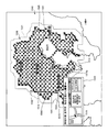
- FIG. 7 is explanatory drawing of an example which shows the reachable position by the navigation apparatus of a present Example by mesh data.
- longitude and latitude information (x, y) of reachable positions searched as shown in FIGS. 5-1 and 5-2 are illustrated in absolute coordinates.
- FIG. 7 illustrates screen data of 64 ⁇ 64 dot mesh data (X, Y) to which identification information is assigned based on the reachable position.
- the navigation apparatus 300 first generates longitude / latitude information (x, y) having a point group 600 in absolute coordinates based on the longitude x and latitude y of each of a plurality of reachable positions. .
- the origin (0, 0) of the longitude / latitude information (x, y) is at the lower left of FIG.
- the navigation device 300 calculates distances w1 and w2 from the longitude ofx of the current position 400 of the vehicle to the maximum longitude x_max and the minimum longitude x_min of the reachable position furthest away in the longitude x direction. Further, the navigation device 300 calculates distances w3 and w4 from the latitude of the current position 400 of the vehicle to the maximum latitude y_max and the minimum latitude y_min of the reachable position farthest in the latitude y direction.
- the current position 400 of the vehicle is composed of mesh data (X, Y) of m ⁇ m dots.
- the navigation device 300 converts the longitude / latitude information (x, y) into mesh data (X, Y), it gives identification information to each area of the mesh data (X, Y), and m rows m It is converted into mesh data of two-dimensional matrix data (Y, X) of columns.
- the navigation device 300 can be used to identify that the vehicle can reach the one area. For example, “1” is given as the identification information (in FIG. 7, one dot is drawn in black, for example).
- the navigation device 300 cannot reach that one vehicle cannot reach the one area. For example, “0” is given as the identification information (in FIG. 7, one dot is drawn in white, for example).
- the navigation device 300 converts the map data into binarized map data of m rows and m columns of two-dimensional matrix data (Y, X) obtained by adding identification information to each area obtained by dividing the map data. Treated as raster data.
- Each area of the mesh data is represented by a rectangular area within a certain range. Specifically, as shown in FIG. 7, for example, m ⁇ m dot mesh data (X, Y) in which a plurality of reachable position point groups 700 are drawn in black is generated. The origin (0, 0) of the mesh data (X, Y) is at the upper left.
- the navigation apparatus 300 changes the identification information given to each area of the m ⁇ m dot mesh data (X, Y) divided as described above. Specifically, the navigation apparatus 300 performs a closing process (a process for performing a reduction process after the expansion process) on mesh data of two-dimensional matrix data (Y, X) of m rows and m columns.
- FIG. 8 is an explanatory diagram showing an example of the closing process by the navigation device of the present embodiment.
- FIGS. 8A to 8C are mesh data of two-dimensional matrix data (Y, X) of m rows and m columns in which identification information is assigned to each region.
- FIG. 8A shows mesh data 800 to which identification information is given for the first time after map data division processing. That is, the mesh data 800 shown in FIG. 8A is the same as the mesh data shown in FIG.
- FIG. 8B shows mesh data 810 after the closing process (expansion) is performed on the mesh data 800 shown in FIG. 8A.
- FIG. 8C shows mesh data 820 after the closing process (reduction) is performed on the mesh data 810 shown in FIG. 8B.
- the vehicle reachable ranges 801, 811 and 821 generated by a plurality of regions to which reachable identification information is assigned are blackened. Shown in a filled state.
- a missing point 802 in the reachable range 801 that is hatched
- the missing point 802 is a node that becomes a reachable position when narrowing down roads for searching for nodes and links in order to reduce the load of the reachable position search processing by the navigation device 300. This occurs when the number is reduced.
- the navigation device 300 performs a closing expansion process on the mesh data 800 after the identification information is added.
- the closing expansion process the identification information of one area adjacent to the area to which the reachable identification information is added in the mesh data 800 after the identification information is added is changed to the reachable identification information.
- the identification information of all the areas adjacent to the outermost area of the reachable range 801 of the vehicle before the expansion process is changed to the reachable identification information.
- the outer periphery of the reachable range 811 of the vehicle after the expansion process is one dot at a time so as to surround the outer periphery of each outermost region of the reachable range 801 of the vehicle before the expansion process every time the expansion process is performed. spread.
- the navigation apparatus 300 performs closing reduction processing on the mesh data 810.
- the closing reduction process the identification information of one area adjacent to the area to which the unreachable identification information is assigned in the mesh data 810 after the expansion process is changed to the unreachable identification information.
- each area on the outermost periphery of the reachable range 811 of the vehicle after the expansion process becomes an area that cannot be reached by one dot every time the reduction process is performed, and the reachable range 811 of the vehicle after the expansion process is reached.
- the outer circumference shrinks.
- the outer periphery of the reachable range 821 of the vehicle after the reduction process is substantially the same as the outer periphery of the reachable range 801 of the vehicle before the expansion process.
- Navigation device 300 performs the above-described expansion process and reduction process the same number of times. Specifically, when the expansion process is performed twice, the subsequent reduction process is also performed twice. By equalizing the number of times of the expansion process and the reduction process, the identification information of almost all areas in the outer periphery of the reachable range of the vehicle that has been changed to the identification information that can be reached by the expansion process is restored to the original information by the reduction process. It can be changed to unreachable identification information. In this way, the navigation device 300 can remove the missing point 802 in the reachable range of the vehicle and generate the reachable range 821 of the vehicle that can clearly display the outer periphery.
- FIG. 9 is an explanatory diagram schematically showing an example of the closing process by the navigation device of the present embodiment.
- FIG. 9A to FIG. 9C show mesh data of two-dimensional matrix data (Y, X) of h rows and h columns in which identification information is assigned to each region as an example.
- FIG. 9A shows the mesh data 900 after the identification information is given.
- FIG. 9B shows mesh data 910 after closing processing (expansion) with respect to FIG.
- FIG. 9C shows mesh data 920 after closing processing (reduction) with respect to FIG.
- areas 901 and 902 to which reachable identification information is assigned are illustrated by different hatchings.
- identification information that can reach the region 901 in the c-row, f-column, f-row, c-column, and g-row, f column is assigned to the mesh data 900 after the identification information is given.
- the regions 901 to which reachable identification information is assigned are arranged apart from each other so that the change in the identification information after the expansion process and the reduction process becomes clear.
- the navigation apparatus 300 performs a closing expansion process on the mesh data 900 having been given such identification information.
- the navigation device 300 includes eight regions adjacent to the lower left, lower, lower right, right, upper right, upper, upper left, and left of the region 901 in the c row and the f column. (B row e column to b row g column, c row e column, c row g column and d row e column to d row g column) 902 identification information is changed from unreachable identification information to reachable identification information change.
- the navigation device 300 can reach the identification information of the eight adjacent regions 902 in the region 901 of the f row c column and the g row f column similarly to the processing performed for the region 901 of the c row f column. Change to the identification information. For this reason, the reachable range 911 of the vehicle is wider than the reachable range of the vehicle in the mesh data 900 after adding the identification information by the amount that the identification information of the area 902 is changed to the reachable identification information.
- the navigation apparatus 300 performs a closing reduction process on the mesh data 910 after the expansion process.
- the navigation device 300 has b rows and e columns adjacent to an area to which unreachable identification information is given (the white background portion of the mesh data 910 after the expansion process).
- the identification information of the eight areas 902 of the b row g column, the c row e column, the c row g column, and the d row e column to the d row g column is changed to unreachable identification information.
- the navigation device 300 is similar to the processing performed on the eight areas 902 of b row e column to b row g column, c row e column, c row g column, and d row e column to d row g column.
- the mesh data 920 after the reduction process is reduced to the three regions 901 to which reachable identification information is added, similarly to the mesh data 900 after the identification information is added.
- a reachable range 921 of the vehicle composed of one region 902 that remains in the state where the reachable identification information is provided even after the processing is generated.
- the region 902 that is provided with the identification information that can be reached during the expansion process and that has been provided with the identification information that can be reached after the reduction process is within the reachable range of the mesh data 900 after the identification information is applied. The missing point that has occurred disappears.
- the navigation device 300 performs an opening process (a process of performing an expansion process after the reduction process) on the mesh data of the two-dimensional matrix data (Y, X), and generates a vehicle reachable range in which the outer periphery can be clearly displayed. May be.
- the navigation apparatus 300 performs an opening process as follows.
- FIG. 10 is an explanatory diagram showing an example of the opening process by the navigation device of the present embodiment.
- FIGS. 10A to 10C are mesh data of two-dimensional matrix data (Y, X) of m rows and m columns in which identification information is assigned to each region.
- FIG. 10A shows mesh data 1000 after identification information is given.
- FIG. 10B shows mesh data 1010 after the opening process (reduction) with respect to FIG.
- FIG. 10C shows mesh data 1020 after the opening process (expansion) with respect to FIG.
- the vehicle reachable ranges 1001, 1011 and 1021 generated by a plurality of regions to which reachable identification information is assigned are blackened. Shown in a filled state.
- the mesh data 1000 after the identification information is added is opened.
- the isolated point 1002 can be removed.
- the navigation device 300 performs an opening reduction process on the mesh data 1000 after the identification information is given.
- the identification information of one area adjacent to the area to which the unreachable identification information is added in the mesh data 1000 after the identification information is added is changed to the unreachable identification information.
- the isolated point 1002 generated in the reachable range 1001 of the vehicle before the reduction process (after the identification information is given) is removed.
- each area on the outermost periphery of the reachable range 1001 of the vehicle after the identification information is added becomes an area that cannot be reached by one dot every time the reduction process is performed, and the reachable range of the vehicle after the identification information is given
- the outer periphery of 1001 shrinks. Further, the isolated point 1002 generated in the reachable range 1001 of the vehicle after the identification information is given is removed.
- the navigation device 300 performs an opening expansion process on the mesh data 1010.
- the identification information of one area adjacent to the area to which the unreachable identification information is added in the mesh data 1010 after the reduction process is changed to the reachable identification information.
- the outer periphery of the reachable range 1021 of the vehicle after the expansion process is one dot at a time so as to surround the outer periphery of each outermost region of the reachable range 1011 of the vehicle after the reduction process every time the expansion process is performed. spread.
- the navigation apparatus 300 performs the expansion process and the reduction process the same number of times in the opening process as in the closing process.
- the outer periphery of the reachable range 1011 of the vehicle shrunk by the reduction process is expanded, and the outer periphery of the vehicle reachable range 1021 after the reduction process is expanded before the reduction process. Can be returned to the outer periphery of the reachable range 1001 of the vehicle.
- the navigation apparatus 300 can generate the vehicle reachable range 1021 in which the isolated point 1002 does not occur and the outer periphery can be clearly displayed.
- the navigation device 300 extracts outlines of the reachable range of the vehicle based on identification information given to mesh data of two-dimensional matrix data (Y, X) of m rows and m columns. Specifically, the navigation apparatus 300 extracts the outline of the reachable range of the vehicle using, for example, a Freeman chain code. More specifically, the navigation apparatus 300 extracts the outline of the reachable range of the vehicle as follows.
- FIG. 11 is an explanatory diagram schematically illustrating an example of vehicle reachable range extraction by the navigation device of the present embodiment.
- FIG. 12 is explanatory drawing which shows typically an example of the mesh data after the vehicle reachable range extraction by the navigation apparatus of a present Example.
- FIG. 11A shows numbers indicating the adjacent directions of the regions 1110 to 1117 adjacent to the region 1100 (hereinafter referred to as “direction index (chain code)”) and eight-direction arrows corresponding to the direction index.
- FIG. 11B shows mesh data 1120 of two-dimensional matrix data (Y, X) of h rows and h columns as an example.
- the areas 1121 to 1134 to which reachable identification information is assigned and the areas to which reachable identification information is enclosed surrounded by the areas 1121 to 1134 are illustrated by hatching.
- the direction index indicates the direction in which the line segment of the unit length is facing.
- the coordinates corresponding to the direction index are (X + dx, Y + dy).
- the direction index in the direction from the region 1100 toward the region 1110 adjacent to the lower left is “0”.
- the direction index in the direction from the region 1100 to the adjacent region 1111 is “1”.
- the direction index in the direction from the region 1100 toward the region 1112 adjacent to the lower right is “2”.
- the direction index in the direction from the region 1100 toward the region 1113 adjacent to the right is “3”.
- the direction index in the direction from the region 1100 toward the region 1114 adjacent to the upper right is “4”.
- the direction index in the direction from the region 1100 toward the adjacent region 1115 is “5”.
- the direction index in the direction from the region 1100 toward the region 1116 adjacent to the upper left is “6”.
- the direction index in the direction from the region 1100 toward the region 1117 adjacent to the left is “7”.
- the navigation device 300 searches the region 1100 adjacent to the region 1100 and provided with the reachable identification information “1” counterclockwise. In addition, the navigation device 300 determines the search start point of the area to which the reachable identification information adjacent to the area 1100 is assigned based on the previous direction index. Specifically, when the direction index from another area toward area 1100 is “0”, navigation apparatus 300 has an area adjacent to the left of area 1100, that is, an area adjacent in the direction of direction index “7”. The search starts from 1117.
- the navigation device 300 is adjacent to the lower left, lower, lower right, right, upper right, upper left of the region 1100.
- the search is started from the matching regions, that is, the regions 1110 to 1116 adjacent in the directions of the direction indices “0”, “1”, “2”, “3”, “4”, “5”, “6”, respectively.
- the navigation apparatus 300 detects the reachable identification information “1” from any one of the areas 1110 to 1117 from the area 1100, the areas 1110 to 1117 in which the reachable identification information “1” is detected.
- the direction indices “0” to “7” corresponding to are written in the storage device in association with the area 1100.
- the navigation device 300 extracts the outline of the reachable range of the vehicle as follows. As shown in FIG. 11 (B), the navigation apparatus 300 first identifies identification that can be reached in units of rows from the region of the a row and the a column of the mesh data 1120 of the two-dimensional matrix data (Y, X) of the h row and the h column. Search for an area to which information is assigned.
- the navigation device 300 Since unreachable identification information is given to all the regions in the a-th row of the mesh data 1120, the navigation device 300 next moves from the region in the b-th row to the b-th column in the mesh data 1120. Search for identification information that can be reached toward the area. Then, after detecting the reachable identification information in the area 1121 in the b row and e column of the mesh data 1120, the navigation apparatus 300 moves counterclockwise from the area 1121 in the b row and e column of the mesh data 1120, and reaches the reachable range of the vehicle. A region having reachable identification information that becomes an outline of the line is searched.
- the navigation device 300 has already searched for the region of b rows and d columns adjacent to the left of the region 1121, and therefore, first, identification is made counterclockwise from the region 1122 adjacent to the lower left of the region 1121. Search whether there is an area having information. Then, the navigation apparatus 300 detects the reachable identification information of the area 1122 and stores the direction index “0” in the direction from the area 1121 to the area 1122 in the storage device in association with the area 1121.
- the navigation apparatus 300 detects the reachable identification information of the area 1123 adjacent to the lower left of the area 1122 and stores the direction index “0” in the direction from the area 1122 to the area 1123 in association with the previous direction index. Store in the device.
- the navigation device 300 determines a search start point based on the previous direction index, and uses the direction index as a process for searching whether there is an area having identification information that can be reached counterclockwise from the search start point. The process is repeated until the corresponding arrow returns to the area 1121. Specifically, navigation device 300 searches whether there is an area having identification information that can be reached counterclockwise from an area adjacent to the left of area 1122, and searches for adjacent area 1124 below area 1123. The reachable identification information is detected, and the direction index “1” is stored in the storage device in association with the previous direction index.
- the navigation device 300 searches for an area having identification information that can be reached counterclockwise from the search start point, and an area having reachable identification information 1124 to 1134 are sequentially detected. Then, every time the navigation device 300 acquires the direction index, the navigation device 300 associates it with the previous direction index and stores it in the storage device.
- navigation device 300 searches counterclockwise from the region of row b and column f adjacent to the upper right of region 1134 to determine whether there is a region having reachable identification information, and adjacent to region 1134.
- the reachable identification information 1121 is detected, and the direction index “5” is stored in the storage device in association with the previous direction index.
- the direction index “0” ⁇ “0” ⁇ “1” ⁇ “0” ⁇ “2” ⁇ “3” ⁇ “4” ⁇ “3” ⁇ “2” ⁇ “5” ⁇ “5” ⁇ “6” ⁇ “6” ⁇ “5” is stored in this order.
- the navigation device 300 sequentially searches the areas 1122 to 1134 having the reachable identification information adjacent to the area 1121 in the counterclockwise direction from the first detected area 1121 to acquire the direction index. Then, the navigation device 300 fills one area in the direction corresponding to the direction index from the area 1121, thereby, as shown in FIG. 12, the part surrounded by the outline 1201 of the reachable range of the vehicle and the outline 1201 Mesh data having a vehicle reachable range of 1202 is generated.
- the navigation device 300 may extract the outline of the reachable range of the vehicle based on the longitude and latitude information of the mesh data of the two-dimensional matrix data (Y, X) to which reachable identification information is assigned. .
- the navigation apparatus 300 extracts the outline of the reachable range of the vehicle as follows.
- FIG. 13 is an explanatory diagram schematically showing another example of vehicle reachable range extraction by the navigation device of the present embodiment.
- the mesh data 1300 of the two-dimensional matrix data (Y, X) of d rows and h columns as shown in FIG. 13 will be described as an example.
- the navigation device 300 searches the mesh data 1300 for the region to which the reachable identification information “1” is assigned. Specifically, the navigation apparatus 300 first searches for identification information “1” that can be reached from the area of the a row and the a column to the area of the a row and the h column.
- the navigation device 300 Since unreachable identification information “0” is assigned to all the regions in the a-th row of the mesh data 1300, the navigation device 300 next moves the region from the b-th row to the b-th column. A region having identification information “1” that can be reached is searched. Then, the navigation apparatus 300 acquires the minimum longitude px1 and the minimum latitude py1 (upper left coordinates of the area 1301) of the area 1301 in the b row and c column having the reachable identification information “1”.
- the navigation device 300 searches for an area having identification information “1” that can be reached from the area of b rows and d columns toward the area of b rows and h columns. Then, the navigation device 300 searches for a boundary between the area having the reachable identification information “1” and the area having the unreachable identification information “0”, and b having the reachable identification information “1”.
- the maximum longitude px2 and the maximum latitude py2 (lower right coordinates of the region 1302) of the region 1302 in the row f column are acquired.
- the navigation device 300 has a rectangular area whose apexes are the upper left coordinates (px1, py1) of the area 1301 of b rows and c columns and the lower right coordinates (px2, py2) of the area 1302 of b rows and f columns. Fill.
- the navigation device 300 searches the mesh data 1300 for the identification information “1” that can be reached from the b row g column to the b row h column area and further from the c row a column to the c row h column.
- the navigation apparatus 300 acquires the minimum longitude px3 and the minimum latitude py3 (upper left coordinates of the area 1303) of the area 1303 in the c row and d column having the reachable identification information “1”.
- the navigation apparatus 300 searches for an area having identification information “1” that can be reached from the area of the c row and the e column toward the area of the c row and the h column. Then, the navigation apparatus 300 searches the boundary between the area having the reachable identification information “1” and the area having the unreachable identification information “0”, and has the reachable identification information “1”.
- the maximum longitude px4 and the maximum latitude py4 (lower right coordinates of the region 1304) of the region 1304 in the row f column are acquired.
- the navigation device 300 has a rectangular area whose apexes are the upper left coordinates (px3, py3) of the area 1303 of c row and d column and the lower right coordinates (px4, py4) of the area 1304 of c row and f column. Fill.
- the navigation device 300 searches for an area having identification information “1” that can be reached from the area of the c row and the g column to the area of the c row and the h column and further from the d row and the a column to the d row and the h column.
- the navigation device 300 ends the process because the unreachable identification information “0” is assigned to all the areas from the c row and g column areas to the d row and h column.
- the navigation apparatus 300 When the navigation device 300 acquires the outline of the reachable range, the navigation apparatus 300 identifies the position on the map that overlaps the outline based on the outline and map data. For example, when the outline line is superimposed on the map, the navigation apparatus 300 acquires the latitude / longitude information of each position on the map located along the outline and stores the latitude / longitude information group in the storage device.
- FIG. 14 is a flowchart illustrating an example of processing performed by the navigation device of the present embodiment.
- the navigation apparatus 300 performs the process shown in the flowchart of FIG. 14 when the user operates the input device 311 and is instructed to display the reachable range.
- the navigation device 300 first acquires the current position (ofx, ofy) of the vehicle on which the device is mounted by the GPS unit 316 or the communication I / F 315 (step S1401).
- the navigation apparatus 300 acquires the initial stored energy amount of the vehicle at the current position (ofx, ofy) of the vehicle through the communication I / F 315 or the like (step S1402).
- the navigation device 300 performs a reachable node search process (step S1403).
- the outline of the reachable node search process is as described with reference to FIGS. 4-1 to 4-4, FIGS. 5-1 and 5-2.
- the navigation apparatus 300 performs mesh data generation and identification information addition processing (step S1404).
- the outline of the mesh data generation and identification information addition processing is as described with reference to FIGS.
- the navigation device 300 extracts the outline of the reachable range of the vehicle (step S1405).
- the outline of the outline extraction of the reachable range is as described with reference to FIGS.
- the navigation apparatus 300 acquires the latitude / longitude information of each position on the map located along the outline when the outline is superimposed on the map, and this latitude / longitude information The group is stored in the storage device.
- the navigation device 300 sets the scale of the map when displaying the reachable range (step S1406).
- step S ⁇ b> 1406 the navigation apparatus 300 sets the entire reachable range among the scales that can be displayed to the largest scale that can be displayed on the display screen of the display 313.
- the navigation device 300 can display the map at a plurality of scales such as a scale of 1/10000, a scale of 1/10000, and a scale of 1 / 1,000,000.
- the navigation device 300 determines whether the reachable range fits within the display screen of the display 313 when the reachable range estimated at the respective scales is displayed, and the scale of the scale determined to fit within the display screen. Set to the largest scale in our house.
- the navigation device 300 sets a designated reception range for displaying regional information based on the outline extracted in step S1405 (step S1407).
- the setting of the designated reception range performed by the navigation device 300 in step S1407 will be described later with reference to FIGS. 15-1 to 15-3.
- the navigation device 300 extracts each position on the map included in the set designated reception range, and stores a longitude / latitude information group representing the position on the map in the storage device.
- the navigation apparatus 300 displays the reachable range on the display 313 (step S1408), and determines whether the designation of the position on the map displayed from the user by the input device 311 or the like has been received (step S1409).
- step S1409 the navigation device 300 determines whether the latitude / longitude of the position on the map designated by the user is the longitude / latitude included in the longitude / latitude information group stored in step S1407. Then, the navigation device 300 determines that the position within the designated reception range has been designated if the latitude and longitude included in the longitude / latitude information group. If the navigation apparatus 300 has not received the designation of the position on the map from the user (step S1409: No), it waits until the designation of the position is accepted.
- step S1409 If the position designation is received from the user (step S1409: YES), the navigation apparatus 300 determines whether the position designated by the user is a position within the designated reception range (step S1410). If it is a position within the designated reception range (step S1410: Yes), the navigation apparatus 300 displays area information corresponding to this position on the display 313 (step S1411), and the process returns to step S1409.
- step S1410 if the position specified by the user is not within the specified reception range (step S1410: No), the navigation apparatus 300 displays a map centered on the position specified by the user on the display 313 (step S1412). ), The process shown in the flowchart of FIG.
- FIG. 15A is an explanatory diagram (part 1) of an example of a specific display by the navigation device of the present embodiment. As illustrated in FIG. 15A, the navigation apparatus 300 displays a map 1510 and a reachable range 1520 on the display 313.
- the map 1510 is a map on a scale that is centered on the current position 1511 of the host vehicle on which the navigation device 300 is mounted and that the reachable range 1520 fits within the display screen of the display 313.
- the navigation apparatus 300 displays a host vehicle icon 1511a indicating the current position of the host vehicle on the current position 1511 in the map 1510.
- the map 1510 is a map for wide area display (for example, a map with a scale of 1 / 1,000,000) based on the reachable range estimated by the navigation device 300.
- the navigation device 300 includes a prefecture name (for example, “Tokyo”, “Kanagawa”, “Saitama”, “Chiba”) and main place names (for example, “Tokyo Bay”, “Sagami”) on the map 1510.
- Bay is displayed, and the name of the municipality is not displayed.
- the boundaries of each prefecture are also displayed in the map for wide area display. In this embodiment, these boundaries are shown in FIG. Not shown.
- the navigation apparatus 300 displays a designated reception range 1530 for displaying regional information based on the outline of the reachable range 1520 (the portion of the reachable range 1520 that is darkly colored) 1521 and the scale of the map 1510. Is set.
- the designated reception range 1530 is a range expanded in each direction away from the current position 1511 than the reachable range 1520 in the map 1510.
- the range included in the dotted line 1531 is the designated acceptance range 1530, and the designated acceptance range 1530 displays the reachable range 1520 in each direction away from the current position 1511.
- This is a range expanded by the length L2 with a display size of 313.
- L2 is predetermined by the manufacturer of the navigation device 300 or the like.
- the designated reception range 1530 moves the reachable range 1520 in each direction away from the current position 1511. The position is included in the area on the map expanded by 10 km.
- the designated reception range 1530 is an area on the map that is extended by 1 km from the reachable range 1520 in each direction away from the current position 1511. It will be included.
- FIG. 15-2 is an explanatory diagram (part 2) illustrating an example of a specific display by the navigation device of the present embodiment.
- the navigation device 300 displays the display screen shown in FIG. 15-2 on the display 313 when the user specifies the position within the specified reception range 1530 while the display screen shown in FIG. To display.
- the navigation apparatus 300 displays the area information 1540 corresponding to the position 1512 on the display 313.
- the area information 1540 is area information of a position 1513 on the outline 1531 that is closest to the position 1512 designated by the user.
- the navigation device 300 displays a map 1541 centered on the position 1513 as the regional information 1540.
- the map 1541 is a map for detailed display than the map 1510, and its scale is larger than that of the map 1510.
- the navigation apparatus 300 can guide a map 1541 including more detailed information than the map 1510 around the position 1513 to the user.
- the navigation device 300 displays the name of the municipality to which the position 1513 belongs and the distance from the current position 1511 to the position 1513 above the map 1541. Thereby, the navigation apparatus 300 can guide the user of the outline of what the position 1513 is.
- the navigation device 300 displays driving support information 1542 as the area information 1540.
- the driving support information 1542 is information that supports a user's driving based on the characteristics around the position 1513. More specifically, in the example shown in FIG. 15B, the navigation apparatus 300 displays a message such as “There is no power supply facility around the specified position” as the driving support information 1542.
- the driving support information 1542 is not limited to the above example, and may be arbitrary information that supports the driving of the user based on the characteristics around the position 1513. Thereby, the navigation apparatus 300 can assist the driving
- the navigation device 300 displays spot information 1543 as the area information 1540.
- the spot information 1543 is information representing facilities existing around the position 1513. For example, in the map data, information indicating whether each facility is a prominent facility is set in advance. Then, the navigation apparatus 300 extracts famous facilities from facilities existing within a predetermined range from the position 1513 (for example, the municipality to which the position 1513 belongs), and displays this list as spot information 1543. Thereby, the navigation apparatus 300 can guide the user to a predetermined facility around the position 1513.
- the navigation apparatus 300 may preferentially display facilities that can supply energy to the own vehicle such as a power supply facility or a gas station in the spot information 1543 to guide the user.
- FIG. 15C is an explanatory diagram (part 3) of an example of a specific display by the navigation device of the present embodiment.
- the navigation device 300 changes the display position and display content of the area information in accordance with this change.
- the position is changed from the position 1512 specified by the user to the position 1514.
- the navigation apparatus 300 displays the area information 1550 on the display 313 as shown in FIG.
- the area information 1550 is area information corresponding to the position 1514.
- the area information 1550 is area information of the position 1515 on the outline 1531 closest to the position 1515. For this reason, as shown in FIG. 15C, the display content of the area information 1550 is different from the area information 1540 at the position 1513 shown in FIG.
- the navigation device 300 displays the area information so as to follow this change. Also good. Specifically, in this case, the navigation apparatus 300 displays a position between the position 1513 and the position 1515 (for example, the position 1516 or the position in FIG. 15-3) after the area information 1540 is displayed and before the area information 1550 is displayed. 1517) is displayed.
- the position on the map 1510 included in the dotted line 1531 is set as the designated reception range, but the present invention is not limited to this. Similar to the example described above with reference to FIG. 1-2, the navigation apparatus 300 sets the boundary line of the designated reception range inside the outline 1531, and the position on the map 1510 between the boundary line and the dotted line 1531 May be set as the designated reception range.
- the navigation device 300 displays the reachable range of the host vehicle on the display 313.
- the navigation device 300 can guide the user how far the vehicle can reach with the energy held by the host vehicle, assisting the user in planning the movement plan based on the reachable range of the host vehicle, Convenience can be improved.
- the navigation apparatus 300 displays the map at a scale that allows the reachable range to fit on one screen of the display 313. Thereby, the navigation apparatus 300 can guide the reachable position in this direction on the display screen 313 of the display 313 regardless of which direction the user proceeds. Therefore, the navigation apparatus 300 can support the planning of the user's movement plan based on the reachable range of the host vehicle, and can improve the convenience for the user. This also allows the user to determine the destination after confirming the entire reachable range.
- the navigation device 300 simplifies information to be displayed on the map, for example, as the map scale is smaller. In other words, the navigation device 300 can display a larger amount of information (detailed information) on the map and guide the information to the user as the scale of the map is larger. Therefore, the navigation apparatus 300 displays a map with the largest scale among the scales that can display the entire reachable range of the host vehicle, thereby guiding the user through the reachable entire area and providing more information to the user. The user can be guided, and the convenience of the user can be improved.
- the navigation device 300 sets the latitude and longitude information of the position on the map included in the designated reception range according to the scale of the map displayed on the display 313. Specifically, the navigation device 300 sets a larger number of latitude / longitude information as the designated reception range when a smaller scale map is displayed. Thereby, the navigation apparatus 300 secures the area of the designation
- the navigation apparatus 300 when the navigation apparatus 300 receives designation of a position on the map displayed on the display 313 from the user, the navigation apparatus 300 can display regional information corresponding to this position if the position is within the designated reception range. . Thereby, the navigation apparatus 300 can guide the user to the area near the outline of the reachable range of the host vehicle desired by the user (that is, near the reachable position of the host vehicle). Thereby, the navigation apparatus 300 can guide the user what area is included in the reachable range even if the map is displayed at a small scale, and the convenience of the user can be improved. . Furthermore, the navigation apparatus 300 may display different regional information depending on the scale of the displayed map when the designation of the position within the designated acceptance range is accepted.
- the navigation apparatus 300 when the navigation apparatus 300 receives a designation of a position within the designated reception range while displaying a map at a scale of 1 million, the navigation apparatus 300 centers the name of the municipality and spot information corresponding to this position and this position. Display a map.
- the navigation apparatus 300 accepts designation of a position within the designated acceptance range while displaying a map at a scale of 10,000, the navigation apparatus 300 displays spot information corresponding to this position and a map centered on this position. (For example, in the case of a scale of 1 in 10,000, the municipality name is already displayed on the map).
- FIG. 16 is a block diagram illustrating an example of a functional configuration of the display control system according to the second embodiment of the present invention.
- the display control system 1600 of the second embodiment is configured by a server 1610 and a terminal 1620, and each of the functional units of the server 1610 and the terminal 1620 includes the display control device 100 described in the first embodiment. Realize the function.
- the server 1610 generates various information used by the terminal 1620 mounted on the moving body for display control of the display unit 110 and transmits the information to the terminal 1620.
- the server 1610 generates information indicating the reachable range of the mobile object and regional information of the position specified by the user, and transmits the information to the terminal 1620.
- the terminal 1620 may be mounted on a mobile body, may be used as a mobile terminal in the mobile body, or may be used outside the mobile body as a mobile terminal.
- the terminal 1620 receives various information used for display control of the display unit 110 from the server 1610.
- the server 1610 includes a server reception unit 1611, an estimation unit 104, and a server transmission unit 1612.
- the terminal 1620 includes a terminal reception unit 1621, a display control unit 101, a reception unit 102, an acquisition unit 103, and a terminal reception unit 1622.
- symbol is attached
- the server reception unit 1611 receives the information transmitted from the terminal 1620. Specifically, for example, the server reception unit 1611 receives information on a mobile body from a terminal 1620 connected to a communication network such as a public line network, a mobile phone network, DSRC, LAN, and WAN via a radio.
- the information related to the moving object can be current position information indicating the current position of the moving object, or information related to the initial amount of energy that is the amount of energy held by the moving object at the current position of the moving object. That is, the information received by the server reception unit 1611 is various information used by the estimation unit 104 to estimate the reachable range.
- the server transmission unit 1612 transmits information indicating the reachable range of the mobile object estimated by the estimation unit 104 to the terminal 1620. Specifically, for example, the server transmission unit 1612 transmits information to a terminal 1620 connected to a communication network such as a public line network, a mobile phone network, a DSRC, a LAN, or a WAN via a radio. In addition, the server transmission unit 1612 may transmit map data necessary for the terminal reception unit 1621 to display the reachable range of the moving object on the display unit 110.
- a communication network such as a public line network, a mobile phone network, a DSRC, a LAN, or a WAN via a radio.
- the server transmission unit 1612 may transmit map data necessary for the terminal reception unit 1621 to display the reachable range of the moving object on the display unit 110.
- the terminal 1620 is connected to the server 1610 in a communicable state via, for example, an information communication network of a mobile terminal or a communication unit (not shown) provided in the own device.
- terminal reception unit 1621 receives information transmitted from server 1610.
- the terminal receiving unit 1621 receives information indicating the reachable range of the mobile object.
- the terminal receiving unit 1621 may receive map data necessary for displaying the reachable range of the moving object on the display unit 110. More specifically, for example, the terminal receiving unit 1621 receives information from a server 1610 that is connected to a communication network such as a public line network, a mobile phone network, DSRC, LAN, and WAN via a wireless connection.
- a communication network such as a public line network, a mobile phone network, DSRC, LAN, and WAN via a wireless connection.
- the terminal transmission unit 1622 transmits the information about the moving object acquired by the acquisition unit 103 to the server 1610. Specifically, for example, the terminal transmission unit 1622 transmits information related to the mobile unit to a server 1610 connected to a communication network such as a public line network, a mobile phone network, DSRC, LAN, and WAN via a wireless connection.
- a communication network such as a public line network, a mobile phone network, DSRC, LAN, and WAN via a wireless connection.
- the same effect as that of the display control device 100 of the first embodiment can be obtained.
- the present invention it is possible to guide the user what kind of area is included in the displayed reachable range, and to create a user movement plan based on the reachable range. To improve user convenience.
- the display control method described in the first and second embodiments is realized by executing a prepared program on a computer such as a personal computer, a workstation, or a mobile terminal (for example, a navigation device or a mobile phone). can do.
- This program is recorded on a computer-readable recording medium such as a hard disk, a flexible disk, a CD-ROM, an MO, and a DVD, and is executed by being read from the recording medium by the computer.
- the program may be a medium that can be distributed via a network such as the Internet.
Abstract
A display control device (100) has a display control section (101) and a reception section (102). The display control section (101) controls the display content of a display section (110) and causes the display section (110) to display a map and the reachable range of a mobile body. The reception section (102) receives designation of a position on the map that is within a prescribed range from the outline of the reachable range. If the reception section (102) received designation of a position on the map that is within a prescribed range from the outline of the reachable range, the display control section (101) causes the display section (110) to display region information corresponding to such position.
Description
本発明は、表示制御装置、サーバ装置、表示制御方法、表示制御プログラムおよび記録媒体に関する。
The present invention relates to a display control device, a server device, a display control method, a display control program, and a recording medium.
従来、車両が現在保有しているエネルギー(例えばガソリンや電気に基づくエネルギー)により到達可能と推定される到達可能範囲をディスプレイに表示させて、ユーザに到達可能範囲を案内する技術が知られている。例えば、このような技術には、地図において自車両の走行可能範囲となる領域に色彩を付したメッシュを表示させるようにしたものがある(例えば、下記特許文献1を参照)。
2. Description of the Related Art Conventionally, a technique is known in which a reachable range estimated to be reachable by energy currently held by a vehicle (for example, energy based on gasoline or electricity) is displayed on a display and the reachable range is guided to a user. . For example, in such a technique, there is a technique in which a mesh with a color is displayed in an area that is a travelable range of the host vehicle on a map (see, for example, Patent Document 1 below).
しかしながら、従来技術にあっては、表示された到達可能範囲にどのような地域が含まれているのかがユーザにとってわかりづらい場合があり、ユーザの利便性の低下につながるという問題が一例として挙げられる。
However, in the prior art, there are cases where it is difficult for the user to understand what kind of area is included in the displayed reachable range, and there is a problem that the user's convenience is reduced as an example. .
上述した課題を解決するため、請求項1の発明にかかる表示制御装置は、移動体の到達可能範囲を地図上に表示させる表示制御手段と、前記到達可能範囲の外郭線から所定範囲内の地図上の位置の指定を受け付ける受付手段と、を備え、前記表示制御手段は、前記受付手段が前記位置の指定を受け付けた場合に、前記位置に対応する地域情報を表示させる、ことを特徴とする。
In order to solve the above-described problem, a display control apparatus according to the invention of claim 1 includes a display control unit that displays a reachable range of a moving object on a map, and a map within a predetermined range from an outline of the reachable range. Receiving means for accepting designation of the upper position, and wherein when the accepting means accepts the designation of the position, the display control means displays area information corresponding to the position. .
また、請求項4の発明にかかるサーバ装置は、移動体の現在位置を取得する現在位置取得手段と、前記移動体の到達可能範囲を推定する推定手段と、受付部により指定された、前記到達可能範囲の外郭線から所定範囲内の位置の情報を取得する指定位置取得手段と、前記指定位置取得手段によって取得された前記位置に対応する地域情報を抽出し、当該地域情報を、端末装置に送信する送信手段と、を備えることを特徴とする。
According to a fourth aspect of the present invention, there is provided a server apparatus comprising: a current position acquisition unit that acquires a current position of a moving body; an estimation unit that estimates a reachable range of the moving body; A specified position acquisition unit that acquires information on a position within a predetermined range from an outline of the possible range, and region information corresponding to the position acquired by the specified position acquisition unit is extracted, and the region information is stored in the terminal device. Transmitting means for transmitting.
また、請求項5の発明にかかる表示制御方法は、表示制御装置が行う表示制御方法であって、移動体の到達可能範囲を地図上に表示させる第1表示工程と、前記到達可能範囲の外郭線から所定範囲内の地図上の位置の指定を受け付ける受付工程と、前記受付工程で前記位置の指定を受け付けた場合に、前記位置に対応する地域情報を表示させる第2表示工程と、を含むことを特徴とする。
The display control method according to the invention of claim 5 is a display control method performed by a display control device, wherein a first display step of displaying a reachable range of a mobile object on a map, and an outline of the reachable range A reception step of receiving designation of a position on a map within a predetermined range from the line, and a second display step of displaying regional information corresponding to the position when the designation of the position is received in the reception step It is characterized by that.
また、請求項6の発明にかかる表示制御プログラムは、請求項5に記載の表示制御方法をコンピュータに実行させることを特徴とする。
The display control program according to the invention of claim 6 causes a computer to execute the display control method according to claim 5.
また、請求項7の発明にかかる記録媒体は、請求項6に記載の表示制御プログラムを記録したことを特徴とする。
Further, a recording medium according to the invention of claim 7 is characterized in that the display control program according to claim 6 is recorded.
以下に添付図面を参照して、本発明にかかる表示制御装置、サーバ装置、表示制御方法、表示制御プログラムおよび記録媒体の好適な実施の形態を詳細に説明する。
Hereinafter, exemplary embodiments of a display control device, a server device, a display control method, a display control program, and a recording medium according to the present invention will be described in detail with reference to the accompanying drawings.
(実施の形態1)
(実施の形態1の表示制御装置の機能的構成)
まず、本発明の実施の形態1について説明する。図1-1は、本発明の実施の形態1にかかる表示制御装置の機能的構成を示すブロック図である。図1-1に示した表示制御装置100は表示部110の表示内容を制御する。図1-1には表示部110が表示制御装置100の外部に設けられた例を示しているが、表示部110は表示制御装置100と一体に設けられていてもよい。 (Embodiment 1)
(Functional Configuration of Display Control Device of Embodiment 1)
First, the first embodiment of the present invention will be described. FIG. 1-1 is a block diagram of a functional configuration of the display control apparatus according to the first embodiment of the present invention. The display control apparatus 100 shown in FIG. 1-1 controls the display content of thedisplay unit 110. FIG. 1-1 shows an example in which the display unit 110 is provided outside the display control device 100, but the display unit 110 may be provided integrally with the display control device 100.
(実施の形態1の表示制御装置の機能的構成)
まず、本発明の実施の形態1について説明する。図1-1は、本発明の実施の形態1にかかる表示制御装置の機能的構成を示すブロック図である。図1-1に示した表示制御装置100は表示部110の表示内容を制御する。図1-1には表示部110が表示制御装置100の外部に設けられた例を示しているが、表示部110は表示制御装置100と一体に設けられていてもよい。 (Embodiment 1)
(Functional Configuration of Display Control Device of Embodiment 1)
First, the first embodiment of the present invention will be described. FIG. 1-1 is a block diagram of a functional configuration of the display control apparatus according to the first embodiment of the present invention. The display control apparatus 100 shown in FIG. 1-1 controls the display content of the
表示制御装置100は表示部110と有線または無線により接続される。表示制御装置100は、この接続を介して表示部110に表示制御信号を出力することにより表示部110の表示内容を制御する。また、例えば、表示制御装置100および表示部110は車両などの移動体に搭載されて用いられる。以下において、表示制御装置100および表示部110を搭載した移動体を単に「移動体」という。
The display control device 100 is connected to the display unit 110 by wire or wireless. The display control apparatus 100 controls the display content of the display unit 110 by outputting a display control signal to the display unit 110 via this connection. Further, for example, the display control device 100 and the display unit 110 are used by being mounted on a moving body such as a vehicle. In the following, a moving body on which the display control device 100 and the display unit 110 are mounted is simply referred to as a “moving body”.
図1-1に示すように、表示制御装置100は、表示制御部101と、受付部102とを含む構成である。表示制御部101は、移動体の到達可能範囲を地図上に表示させる機能を有する。例えば、表示制御部101は、表示制御装置100に設けられた取得部103や推定部104から受け付けた各種情報を用いて、移動体の現在位置を中心とした所定範囲の地図を表示部110に表示させ、この地図で移動体の到達可能範囲となる領域には到達可能範囲であることを示す画像を表示させる。ここで、移動体の到達可能範囲は、例えば移動体が現在保有するエネルギーを消費しきるまで移動した際に到達可能な地図上の範囲である。
As shown in FIG. 1-1, the display control apparatus 100 includes a display control unit 101 and a reception unit 102. The display control unit 101 has a function of displaying the reachable range of the moving object on the map. For example, the display control unit 101 uses the various types of information received from the acquisition unit 103 and the estimation unit 104 provided in the display control device 100 to display a map in a predetermined range centered on the current position of the moving object on the display unit 110. In this map, an image indicating the reachable range is displayed in an area that is the reachable range of the moving object. Here, the reachable range of the mobile body is, for example, a range on the map that can be reached when the mobile body has moved until it has consumed the energy it currently holds.
移動体が保有するエネルギーには、電気に基づくエネルギー、ガソリンや軽油やガスなどに基づくエネルギーなどが挙げられる。具体的に、移動体が保有するエネルギーは、移動体がEV(Electric Vehicle)車の場合には電気に基づくエネルギーとなる。また、移動体が保有するエネルギーは、移動体がHV(Hybrid Vehicle)車やPHV(Plug-in Hybrid Vehicle)車などの場合には電気に基づくエネルギーおよびガソリンや軽油やガスなどに基づくエネルギーとなる。
The energy held by the mobile body includes energy based on electricity, energy based on gasoline, light oil, gas, and the like. Specifically, the energy held by the moving body is energy based on electricity when the moving body is an EV (Electric Vehicle) vehicle. In addition, when the mobile body is an HV (Hybrid Vehicle) vehicle or a PHV (Plug-in Hybrid Vehicle) vehicle, the energy held by the mobile body is energy based on electricity and energy based on gasoline, light oil, gas, etc. .
さらに、移動体が保有するエネルギーは、移動体が燃料電池車の場合には電気に基づくエネルギーおよび水素や水素の原料になる化石燃料となる。例えば、移動体は、移動体のバッテリーに電気を蓄えることにより、移動体の燃料タンクにガソリンや軽油を蓄えることにより、または移動体の高圧タンクにガスを蓄えることにより、上述の各エネルギーを保有することができる。
Furthermore, when the moving body is a fuel cell vehicle, the energy held by the moving body becomes energy based on electricity and fossil fuel that becomes a raw material of hydrogen or hydrogen. For example, the mobile body holds each energy described above by storing electricity in the battery of the mobile body, storing gasoline or light oil in the fuel tank of the mobile body, or storing gas in the high-pressure tank of the mobile body. can do.
取得部103は、表示制御部101が表示制御に用いる各種情報を表示制御装置100の内部または外部から取得して、取得した情報を表示制御部101へ出力する機能を有する。例えば、取得部103が取得する情報としては、現在位置情報や地図データを挙げることができる。
The acquisition unit 103 has a function of acquiring various types of information used by the display control unit 101 for display control from the inside or the outside of the display control device 100 and outputting the acquired information to the display control unit 101. For example, information acquired by the acquisition unit 103 can include current position information and map data.
ここで、現在位置情報は移動体の現在位置を示す情報である。例えば、移動体には、GPS(Global Positioning System)ユニットが搭載される。GPSについては公知の技術であるために詳細な説明を省略するが、GPSユニットは複数のGPS衛星からのGPSシグナル(電波)を受信することにより移動体の現在位置を測位して、測位結果を取得部103へ出力する。これにより、取得部103は現在位置情報を取得することができる。
Here, the current position information is information indicating the current position of the moving object. For example, a GPS (Global Positioning System) unit is mounted on the moving body. Since GPS is a well-known technology, detailed description is omitted, but the GPS unit receives the GPS signals (radio waves) from a plurality of GPS satellites to determine the current position of the moving object, and displays the positioning result. The data is output to the acquisition unit 103. Thereby, the acquisition unit 103 can acquire current position information.
例えば、地図データは、建物、河川、地表面などの地物(フィーチャ)をあらわす背景データや、道路の形状をリンクやノードなどであらわす道路形状データなどから構成されるデータである。また、地図データには、地図上の各位置についての住所を示す情報などが含まれる。さらに、地図データには移動体の到達可能範囲の推定に用いられる情報が含まれていてもよい。例えば、到達可能範囲の推定に用いられる情報には、各リンクを移動体が移動する際に消費すると推定されるエネルギー量(以下「消費推定エネルギー量」という)をあらわす情報などを挙げることができる。
For example, map data is data composed of background data representing features (features) such as buildings, rivers, and the ground surface, and road shape data representing road shapes with links and nodes. Also, the map data includes information indicating addresses for each position on the map. Further, the map data may include information used for estimating the reachable range of the mobile object. For example, the information used for estimating the reachable range may include information representing the amount of energy estimated to be consumed when the mobile body moves on each link (hereinafter referred to as “consumed energy consumption amount”). .
地図データは表示制御装置100の製造者により表示制御装置100の所定の記憶領域に予め記憶されており、取得部103はこの記憶領域から地図データを読み出すことにより地図データを取得する。また、地図データは表示制御装置100とは別の装置(外部)に記憶されていてもよい。この場合、表示制御装置100と地図データを記憶した装置とは有線または無線により接続され、取得部103はこの接続を介して地図データを記憶した装置から地図データを取得する。
The map data is stored in advance in a predetermined storage area of the display control apparatus 100 by the manufacturer of the display control apparatus 100, and the acquisition unit 103 acquires the map data by reading the map data from this storage area. The map data may be stored in a device (external) different from the display control device 100. In this case, the display control device 100 and the device storing the map data are connected by wire or wireless, and the acquisition unit 103 acquires the map data from the device storing the map data via this connection.
推定部104は移動体の到達可能範囲を推定して、推定した移動体の到達可能範囲を示す情報を表示制御部101へ出力する機能を有する。推定部104は任意の推定方法を用いて移動体の到達可能範囲を推定してよい。推定部104による到達可能範囲の推定方法の一例を挙げれば、移動体が現在位置にて保有する初期保有エネルギー量および消費推定エネルギー量に基づく推定がある。
The estimation unit 104 has a function of estimating the reachable range of the moving object and outputting information indicating the estimated reachable range of the moving object to the display control unit 101. The estimation unit 104 may estimate the reachable range of the moving object using any estimation method. If an example of the reachable range estimation method by the estimation unit 104 is given, there is an estimation based on the initial stored energy amount and the estimated consumption energy amount that the mobile body holds at the current position.
この場合、推定部104は取得部103を介して現在位置情報および地図データを取得する。また、推定部104はCAN(Controller Area Network)などの通信プロトコルによって動作する車内通信網を介してエレクトロニックコントロールユニット(ECU:Electronic Control Unit)により管理された移動体の初期保有エネルギー量を取得する。
In this case, the estimation unit 104 acquires the current position information and map data via the acquisition unit 103. In addition, the estimation unit 104 acquires an initial amount of energy held by a mobile body managed by an electronic control unit (ECU) via an in-vehicle communication network that operates according to a communication protocol such as CAN (Controller Area Network).
そして、推定部104は、現在位置に対応するノードと、このノードに隣接する他のノードとを接続するリンクの消費推定エネルギー量を地図データから取得する。つづいて、推定部104は、上記他のノードと、さらにこのノードに隣接するノード(現在位置に対応するノードでないノード)とを接続するリンクの消費推定エネルギー量を地図データから取得する。このように、推定部104は現在位置に対応するノードからツリー状にリンクを伸ばしていき、このリンク群の消費推定エネルギー量の累積値を算出する。
And the estimation part 104 acquires the consumption estimated energy amount of the link which connects the node corresponding to a present position, and the other node adjacent to this node from map data. Subsequently, the estimation unit 104 acquires the estimated energy consumption of a link connecting the other node and a node adjacent to this node (a node not corresponding to the current position) from the map data. In this way, the estimation unit 104 extends a link from the node corresponding to the current position in a tree shape, and calculates the cumulative value of the estimated energy consumption of this link group.
そして、推定部104は、消費推定エネルギー量の累積値が初期保有エネルギー量よりも大きくなった一つ前のノードを移動体の到達可能位置として特定する。一般的には到達可能位置は複数特定されることになる。推定部104は、特定した複数の到達可能位置から、例えばペジェ曲線やスプライン曲線を導き、この曲線に包含される地図上の範囲を到達可能範囲とする。そして、推定部104は到達可能範囲に含まれる地図上の各位置の位置座標(例えば緯度経度)群を、到達可能範囲を示す情報として表示制御部101へ出力する。
Then, the estimation unit 104 identifies the previous node where the accumulated value of the estimated consumption energy amount is larger than the initial stored energy amount as the reachable position of the mobile object. In general, a plurality of reachable positions are specified. The estimation unit 104 derives, for example, a Pezier curve or a spline curve from the plurality of specified reachable positions, and sets a range on the map included in the curve as the reachable range. Then, the estimation unit 104 outputs a position coordinate (for example, latitude and longitude) group of each position on the map included in the reachable range to the display control unit 101 as information indicating the reachable range.
表示制御部101は、取得部103から受け付けた現在位置情報および地図データ、推定部104から受け付けた到達可能範囲を示す情報を用いることにより、移動体の現在位置を中心とした所定範囲(例えば表示させる地図の縮尺に応じた範囲)の地図を表示部110に表示させ、さらにこの地図において移動体の到達可能範囲となる領域には到達可能範囲であることを示す画像を表示させることができる。
The display control unit 101 uses the current position information and map data received from the acquisition unit 103, and information indicating the reachable range received from the estimation unit 104, so that a predetermined range centered on the current position of the moving object (for example, display A map corresponding to the scale of the map to be displayed) is displayed on the display unit 110, and an image indicating the reachable range can be displayed in the area that is the reachable range of the moving object on the map.
また、表示制御部101は複数の縮尺を用いて地図を表示させることができる。例えば、表示制御部101は、1万分の1の縮尺、10万分の1の縮尺、100万分の1の縮尺といったように予め設けられた複数の縮尺の中のいずれか縮尺を用いて地図を表示させることができる。1万分の1の縮尺では100mの実距離が1cmの表示サイズで表示され、100万分の1の縮尺では10kmの実距離が1cmの表示サイズで表示されることになる。
Also, the display control unit 101 can display a map using a plurality of scales. For example, the display control unit 101 displays a map using any one of a plurality of scales provided in advance such as a scale of 1 / 10,000, a scale of 1 / 100,000, or a scale of 1 / 1,000,000. Can be made. An actual distance of 100 m is displayed at a display size of 1 cm at a scale of 1/10000, and an actual distance of 10 km is displayed at a display size of 1 cm at a scale of 1/1000.
地図を表示させる際、表示制御部101はその縮尺に応じて地図に表示させる情報を異ならせる。すなわち、例えば、100万分の1の縮尺では10kmの実距離が1cmの表示サイズで表示されることになるが、このような広域表示用の地図で地図上の各位置について詳細な情報を表示させると、情報が密になり過ぎてユーザにとって見づらいものとなる。
When displaying a map, the display control unit 101 varies the information displayed on the map according to the scale. That is, for example, an actual distance of 10 km is displayed with a display size of 1 cm at a scale of 1 / 1,000,000. Detailed information about each position on the map is displayed on such a map for wide area display. The information becomes too dense and difficult for the user to see.
そこで、表示制御部101は、広域表示用の地図(例えば100万分の1の縮尺の地図)を表示させる場合には詳細表示用の地図(例えば1万分の1の縮尺の地図)よりも簡略化した情報を表示させる。より具体的に、例えば、表示制御部101は、100万分の1の縮尺の地図を表示させる際には都道府県名のみを地図に表示させ、1万分の1の縮尺の地図を表示させる際には都道府県名、市町村名、道路名、交差点名を地図に表示させる。これにより、表示制御部101は表示時の縮尺によらず地図の視認性を担保することができる。
Therefore, when displaying a map for wide area display (for example, a map with a scale of 1 / 1,000,000), the display control unit 101 is more simplified than a map for detailed display (for example, a map with a scale of 1 / 10,000). Displayed information. More specifically, for example, when the display control unit 101 displays a map with a scale of 1 / 1,000,000, the display control unit 101 displays only a prefecture name on the map and displays a map with a scale of 1 / 10,000. Displays the prefecture name, city name, road name, and intersection name on the map. Thereby, the display control part 101 can ensure the visibility of a map irrespective of the reduced scale at the time of a display.
一例として、本実施の形態1では、表示制御部101は推定された到達可能範囲を表示させる際、到達可能範囲全域が表示部110の表示画面内に収まる縮尺を予め用意された複数の縮尺の中から選択し、選択した縮尺の地図を表示部110に表示させる(例えば後述する図1-2を参照)。
As an example, in the first embodiment, when displaying the estimated reachable range, the display control unit 101 has a plurality of scales prepared in advance so that the entire reachable range is within the display screen of the display unit 110. A map of the selected scale is selected and displayed on the display unit 110 (see, for example, FIG. 1-2 described later).
また、表示制御部101は、表示部110の表示画面の大きさや画面解像度に応じて地図に表示させる情報を簡略化したり詳細化したりしてもよい。例えば、この場合、表示制御部101は、取得部103を介して表示部110から表示部110の表示画面の大きさや画面解像度を示す情報を取得する。そして、表示制御部101は、表示部110の表示画面の大きさや画面解像度が小さいほど地図に表示させる情報を簡略化する。これにより、表示制御部101は表示部110のハードウェア性能によらず地図の視認性を担保することができる。
Further, the display control unit 101 may simplify or detail the information to be displayed on the map according to the size of the display screen of the display unit 110 and the screen resolution. For example, in this case, the display control unit 101 acquires information indicating the size and screen resolution of the display screen of the display unit 110 from the display unit 110 via the acquisition unit 103. And the display control part 101 simplifies the information displayed on a map, so that the magnitude | size and screen resolution of the display screen of the display part 110 are small. Thereby, the display control unit 101 can ensure the visibility of the map regardless of the hardware performance of the display unit 110.
受付部102は、ユーザにより指定された位置に関する情報を表示制御部101へ出力する機能を有する。例えば、ここで、位置に関する情報は、ユーザにより指定された地図上の位置の位置座標(例えば緯度・経度)を示す情報とすることができる。より具体的には、表示部110の表示画面がタッチパネルの場合、受付部102は、まず、タッチパネルの表面に生じた圧力などから表示画面上のいずれの位置をユーザが指定したか(触れたか)を特定する。つぎに、受付部102は、表示制御部101から表示部110に表示させている地図を示す情報を受け付けて、ユーザが指定した表示画面上の位置に表示されている地図上の位置を特定し、この位置に関する情報を表示制御部101へ出力する。
The reception unit 102 has a function of outputting information related to the position designated by the user to the display control unit 101. For example, here, the information regarding the position can be information indicating the position coordinates (for example, latitude and longitude) of the position on the map designated by the user. More specifically, when the display screen of the display unit 110 is a touch panel, the reception unit 102 first determines which position on the display screen the user has specified (touched) from the pressure generated on the surface of the touch panel. Is identified. Next, the receiving unit 102 receives information indicating the map displayed on the display unit 110 from the display control unit 101, and specifies the position on the map displayed at the position on the display screen designated by the user. Then, information regarding this position is output to the display control unit 101.
なお、上記の例では、受付部102がユーザにより指定された表示画面上の位置を地図上の位置に変換して、この位置に関する情報を表示制御部101へ出力する構成としたがこれに限らない。例えば、受付部102がユーザにより指定された表示画面上の位置を示す情報を表示制御部101へ出力し、表示制御部101がユーザにより指定された表示画面上の位置に表示させていた地図上の位置を特定するようにしてもよい。
In the above example, the reception unit 102 converts the position on the display screen designated by the user into a position on the map, and outputs information about the position to the display control unit 101. However, the present invention is not limited thereto. Absent. For example, the information indicating the position on the display screen specified by the user is output to the display control unit 101 by the reception unit 102, and the map displayed on the display screen specified by the user on the display screen is displayed on the map. The position may be specified.
特に、本実施の形態1において、受付部102は、表示部110に表示された到達可能範囲の外郭線から所定範囲内の地図上の位置の指定を受け付ける。ここで、到達可能範囲の外郭線からの所定範囲は、表示制御装置100の製造者により予め定められた一定範囲でもよいし、条件により変動する範囲であってもよい。詳細は図1-2などを用いて後述するが、例えば本実施の形態1において、到達可能範囲の外郭線からの所定範囲は表示された地図の縮尺に応じて変動するものとする。また、以下において、到達可能範囲の外郭線からの所定範囲を「指定受付範囲」という。
In particular, in the first embodiment, the accepting unit 102 accepts designation of a position on a map within a predetermined range from the outline of the reachable range displayed on the display unit 110. Here, the predetermined range from the outline of the reachable range may be a predetermined range determined in advance by the manufacturer of the display control apparatus 100, or may be a range that varies depending on conditions. The details will be described later with reference to FIG. 1-2 and the like. For example, in the first embodiment, the predetermined range from the outline of the reachable range varies according to the scale of the displayed map. In the following, the predetermined range from the outline of the reachable range is referred to as “designated reception range”.
表示制御部101は、受付部102が指定受付範囲内の地図上の位置の指定を受け付けた場合に、指定された位置に対応する地域情報を表示部110に表示させる。例えば、ここで、地域情報は、或る位置の市町村名(すなわち住所の一部)をあらわす情報や、或る位置が属する地域に存在する施設をあらわす情報とすることができる。また、地域情報は、或る位置を中心とした地図であってもよい。
The display control unit 101 causes the display unit 110 to display area information corresponding to the specified position when the reception unit 102 receives the designation of the position on the map within the designated reception range. For example, here, the area information can be information indicating the name of a municipality at a certain position (that is, a part of an address) or information indicating a facility existing in an area to which a certain position belongs. The regional information may be a map centered on a certain position.
また、指定された位置に対応する地域情報とは、指定された位置の地域情報であってもよいし、指定された位置周辺の他の位置の地域情報であってもよい。例えば、本実施の形態1において、指定された位置に対応する地域情報は、指定された位置に直近の到達可能範囲の外郭線上の位置の地域情報とする。表示制御部101は、指定された位置に対応する地域情報を地図データから抽出して、抽出した地域情報を表示部110に表示させる。
Further, the area information corresponding to the designated position may be area information of the designated position, or may be area information of other positions around the designated position. For example, in the first embodiment, the area information corresponding to the designated position is the area information of the position on the outline of the reachable range closest to the designated position. The display control unit 101 extracts region information corresponding to the designated position from the map data, and causes the display unit 110 to display the extracted region information.
また、表示制御部101は、地域情報を表示させる場合、到達可能範囲と地域情報を関連付けて同時に表示させてもよい。例えば、上述のように、表示制御部101は指定された位置に直近の到達可能範囲の外郭線上の位置の地域情報を表示させるが、この際にはいずれの位置(すなわち上記外郭線上の位置)の地域情報が表示されているかをユーザに明示するようにして表示させる。
Further, when displaying the region information, the display control unit 101 may display the reachable range and the region information in association with each other at the same time. For example, as described above, the display control unit 101 displays the area information of the position on the outline of the latest reachable range at the designated position, and in this case, any position (that is, the position on the outline) It is made to display so that it may be clearly shown to the user whether the local information of is displayed.
(実施の形態1の表示制御装置による表示内容および指定受付範囲の一例)
ここで、表示制御装置100による表示内容および指定受付範囲の一例について説明する。図1-2は、本実施の形態1の表示制御装置による表示内容および指定受付範囲の一例を示す説明図である。図1-2に示すように、表示制御装置100は表示部110の表示画面に地図120を表示させ、地図120上の移動体の到達可能範囲となる領域には到達可能範囲(画像)130を表示させる。 (Example of display contents and designated reception range by the display control apparatus of the first embodiment)
Here, an example of display contents and a specified reception range by the display control apparatus 100 will be described. FIG. 1-2 is an explanatory diagram illustrating an example of display contents and a specified reception range by the display control apparatus according to the first embodiment. As shown in FIG. 1-2, the display control apparatus 100 displays amap 120 on the display screen of the display unit 110, and a reachable range (image) 130 is displayed in an area that is a reachable range of the moving object on the map 120. Display.
ここで、表示制御装置100による表示内容および指定受付範囲の一例について説明する。図1-2は、本実施の形態1の表示制御装置による表示内容および指定受付範囲の一例を示す説明図である。図1-2に示すように、表示制御装置100は表示部110の表示画面に地図120を表示させ、地図120上の移動体の到達可能範囲となる領域には到達可能範囲(画像)130を表示させる。 (Example of display contents and designated reception range by the display control apparatus of the first embodiment)
Here, an example of display contents and a specified reception range by the display control apparatus 100 will be described. FIG. 1-2 is an explanatory diagram illustrating an example of display contents and a specified reception range by the display control apparatus according to the first embodiment. As shown in FIG. 1-2, the display control apparatus 100 displays a
具体的に、表示制御装置100は移動体の現在位置121を中心とし、且つ、到達可能範囲130が表示部110の表示画面内に収まる縮尺の地図120を表示部110の表示画面に表示させる。例えば、図1-2に示すように、到達可能範囲130の水平方向の表示サイズ(長さ)をW1とし、垂直方向の表示サイズ(長さ)をH1とする。また、表示部110の表示画面の水平方向の長さをW2とし、垂直方向の長さをH2とする。
Specifically, the display control apparatus 100 displays on the display screen of the display unit 110 a scaled map 120 centered on the current position 121 of the moving object and the reachable range 130 within the display screen of the display unit 110. For example, as shown in FIG. 1-2, the horizontal display size (length) of the reachable range 130 is W1, and the vertical display size (length) is H1. Further, the horizontal length of the display screen of the display unit 110 is W2, and the vertical length is H2.
この場合、表示制御装置100は推定部104により推定された移動体の到達可能範囲が広いほど縮尺が小さくなるように設定して、W1<W2且つH1<H2となる縮尺の地図120を表示させる。これにより、表示制御装置100は推定部104により任意の広さの到達可能範囲が推定されても、到達可能範囲130が表示部110の表示画面内に収まるように表示させることができる。そして、表示制御装置100は推定部104により推定された到達可能範囲全域を一画面でユーザに見せることができる。
In this case, the display control apparatus 100 displays a map 120 with a scale that satisfies W1 <W2 and H1 <H2 by setting the scale to be smaller as the reachable range of the moving object estimated by the estimation unit 104 is wider. . Thereby, even if the reachable range of an arbitrary width is estimated by the estimation unit 104, the display control apparatus 100 can display the reachable range 130 so as to be within the display screen of the display unit 110. Then, the display control apparatus 100 can show the entire reachable range estimated by the estimation unit 104 to the user on one screen.
このため、表示制御装置100は、表示部110の表示画面一画面で、ユーザがいずれの方向に進もうとしてもこの方向における到達可能位置を案内することができる。したがって、表示制御装置100はユーザの到達可能範囲に基づく移動計画(例えば所望の位置まで移動するにはエネルギーの補給が必要か、エネルギーの補給はどの辺りでした方がよいか)の立案を支援することができ、ユーザの利便性を向上させることができる。また、これにより、ユーザは到達可能範囲全域を確認した上で目的地を決定することもできるようにもなる。
For this reason, the display control device 100 can guide the reachable position in this direction on the screen of the display unit 110 regardless of which direction the user proceeds. Therefore, the display control apparatus 100 supports the planning of a movement plan based on the reachable range of the user (for example, whether it is necessary to replenish energy to move to a desired position, or which area should be replenished with energy). It is possible to improve user convenience. This also allows the user to determine the destination after confirming the entire reachable range.
また、表示制御装置100は、W1<W2且つH1<H2を満たす最も大きな縮尺の地図120を表示させるようにしてもよい。例えば、上述したように、表示制御部101が1万分の1の縮尺、10万分の1の縮尺、100万分の1の縮尺といった複数の縮尺で地図を表示させることができる。表示制御部101は、それぞれの縮尺で推定部104により推定された到達可能範囲を表示させた場合に、W1<W2且つH1<H2を満たすか否かを判定し、W1<W2且つH1<H2を満たす縮尺のうちで最も大きな縮尺の地図を表示させる。
Further, the display control device 100 may display the largest scale map 120 that satisfies W1 <W2 and H1 <H2. For example, as described above, the display control unit 101 can display the map at a plurality of scales such as a scale of 1 / 10,000, a scale of 1 / 100,000, and a scale of 1 / 1,000,000. The display control unit 101 determines whether or not W1 <W2 and H1 <H2 are satisfied when displaying the reachable range estimated by the estimation unit 104 at each scale, and W1 <W2 and H1 <H2 The map with the largest scale among the scales that satisfy the condition is displayed.
表示制御部101は、地図の視認性を担保する観点から、地図の縮尺が小さいほど地図に表示させる情報を簡略化する。換言すれば、表示制御装置100は、地図の縮尺が大きいほど多くの情報(詳細な情報)を地図に表示させてこれらの情報をユーザに案内することができる。このため、表示制御部101はW1<W2且つH1<H2を満たす最も大きな縮尺の地図を表示させることにより、到達可能範囲全域をユーザに案内しつつも、ユーザにより多くの情報を案内することができるようになり、ユーザの利便性の向上を図ることができる。
The display control unit 101 simplifies information to be displayed on the map as the map scale is smaller from the viewpoint of ensuring the visibility of the map. In other words, the display control apparatus 100 can display more information (detailed information) on the map and guide the information to the user as the scale of the map is larger. For this reason, the display control unit 101 displays the largest scale map satisfying W1 <W2 and H1 <H2, thereby guiding the user to more information while guiding the entire reachable range to the user. As a result, the convenience of the user can be improved.
なお、例えば、図1-2に示す地図120は100万分の1の縮尺の広域表示用の地図となっており、地図120上には「A県」、「B県」、「C県」といった都道府県名のみが表示されている。
Note that, for example, the map 120 shown in FIG. 1-2 is a map for wide-area display with a scale of 1 / 1,000,000, and on the map 120, “A prefecture”, “B prefecture”, “C prefecture”, etc. Only the prefecture name is displayed.
また、表示制御装置100は地域情報を表示させるための指定受付範囲を設定する。表示制御装置100は、到達可能範囲130の外郭線131を基準に指定受付範囲を設定する。図1-2に示す例では、表示制御装置100は点線141に包含される領域に含まれる地図上の各位置を指定受付範囲として設定している。
Further, the display control device 100 sets a designated reception range for displaying the area information. The display control apparatus 100 sets the designated reception range based on the outline 131 of the reachable range 130. In the example shown in FIG. 1-2, the display control apparatus 100 sets each position on the map included in the area included in the dotted line 141 as the designated reception range.
ここで、点線141は外郭線131を表示部110の表示サイズで長さL1分だけ現在位置121から離れる方向に拡張された線である。例えば、縮尺が100万分の1の地図120の場合、L1が1cmだとすると、指定受付範囲は到達可能範囲を現在位置121から離れる各々の方向に10kmずつ拡張された地図上の領域に含まれる位置となる。
Here, the dotted line 141 is a line obtained by extending the outline 131 in the direction away from the current position 121 by the length L1 in the display size of the display unit 110. For example, in the case of a map 120 having a scale of 1 / 1,000,000, if L1 is 1 cm, the designated reception range is a position included in an area on the map that is extended by 10 km in each direction away from the current position 121. Become.
一方、例えば、縮尺が10万分の1の地図の場合には、L1が1cmだとすると、指定受付範囲は到達可能範囲を現在位置121から離れる各々の方向に1kmずつ拡張された地図上の領域に含まれる位置となる。このように、表示制御装置100は表示部110に表示させる地図の縮尺に応じて指定受付範囲を設定する。より具体的には、表示制御装置100は小さな縮尺の地図を表示させるときほど多数の地図上の位置を指定受付範囲として設定する。これにより、表示制御装置100は地図の縮尺を小さくすることに伴って指定受付範囲も狭くなってしまうことを抑止することができ、指定受付範囲内の位置を指定する際のユーザの操作性を向上させて、ユーザの利便性を向上させることができる。
On the other hand, for example, in the case of a map with a scale of 1 / 100,000, if L1 is 1 cm, the designated reception range is included in the area on the map extended by 1 km in each direction away from the current position 121 from the reachable range. It becomes a position to be. Thus, the display control apparatus 100 sets the designated reception range according to the scale of the map displayed on the display unit 110. More specifically, the display control apparatus 100 sets a larger number of map positions as the designated reception range when displaying a smaller scale map. Thereby, the display control apparatus 100 can suppress that the designation | designated reception range also becomes narrow with reducing the scale of a map, and user's operativity at the time of designating the position in a designation | designated reception range is improved. It is possible to improve user convenience.
また、表示制御装置100は、点線142で示すように外郭線131の外側だけでなく内側にも指定受付範囲の境界を設定してもよい。例えば、ここで点線142は外郭線131を表示部110の表示サイズで長さL1分だけ現在位置121へ向かう方向に縮小された線である。例えば、この場合、指定受付範囲は点線141と点線142との間の領域に含まれる地図上の位置となる。
Further, the display control apparatus 100 may set the boundary of the designated reception range not only on the outer side of the outline 131 but also on the inner side as indicated by the dotted line 142. For example, the dotted line 142 is a line obtained by reducing the outline 131 in the direction toward the current position 121 by the length L1 in the display size of the display unit 110. For example, in this case, the designated reception range is a position on the map included in the area between the dotted line 141 and the dotted line 142.
そして、表示制御装置100は、指定受付範囲内の位置122がユーザによって指定された場合、位置122に対応する地域情報150を表示部110に表示させる。例えば、このとき、表示制御装置100は、位置122に直近の外郭線131上の位置である位置123の地域情報150を表示させる。
And the display control apparatus 100 displays the area information 150 corresponding to the position 122 on the display part 110, when the position 122 in the designation | designated reception range is designated by the user. For example, at this time, the display control apparatus 100 displays the area information 150 of the position 123 that is the position on the outer outline 131 nearest to the position 122.
図1-2に例示する地域情報150は、位置123が○○市に含まれる位置であるために「○○市」という市町村名を示すものとなっている。また、表示制御部101は、ユーザにいずれの位置の地域情報が表示されているのかを明示するため、位置123から「吹き出し」を出してこの「吹き出し」の中に「○○市」という市町村名を表示させた地域情報150としている。
In the area information 150 illustrated in FIG. 1-2, the location 123 is a location included in XX city, and therefore indicates the name of a municipality “XX city”. Further, the display control unit 101 issues a “speech balloon” from the position 123 in order to clearly indicate to the user which location information is displayed, and a municipality “XX city” is included in this “speech balloon”. The area information 150 displays the name.
(本実施の形態1の表示制御装置が行う処理の一例)
つぎに、表示制御装置100が行う処理の一例について説明する。図2は、本実施の形態1の表示制御装置が行う処理の一例を示すフローチャートである。例えば、表示制御装置100はユーザから到達可能範囲を表示するよう指示された場合に、図2のフローチャートに示す処理を行う。 (Example of processing performed by the display control apparatus according to the first embodiment)
Next, an example of processing performed by the display control apparatus 100 will be described. FIG. 2 is a flowchart illustrating an example of processing performed by the display control apparatus according to the first embodiment. For example, when the display control apparatus 100 is instructed by the user to display the reachable range, the display control apparatus 100 performs the process shown in the flowchart of FIG.
図2に示すように、まず、表示制御装置100は表示部110の表示画面に到達可能範囲を表示させる(ステップS201)。つぎに、表示制御装置100はユーザから地図上の位置の指定を受け付けたかを判定する(ステップS202)。ユーザから地図上の位置の指定を受け付けていなければ(ステップS202:No)、表示制御装置100は位置の指定を受け付けるまで待機する。
As shown in FIG. 2, first, the display control apparatus 100 displays the reachable range on the display screen of the display unit 110 (step S201). Next, the display control apparatus 100 determines whether designation of a position on the map has been received from the user (step S202). If the designation of the position on the map is not received from the user (step S202: No), the display control apparatus 100 stands by until the designation of the position is accepted.
ユーザから地図上の位置の指定を受け付けた場合(ステップS202:Yes)、表示制御装置100はユーザにより指定された地図上の位置が到達可能範囲の外郭線から所定範囲(指定受付範囲)内の位置であるかを判定する(ステップS203)。例えば、表示制御装置100は指定受付範囲を設定すると、指定受付範囲に含まれる地図上の各位置を抽出し、これらの位置座標をあらわす位置座標群を所定の記憶領域に記憶しておく。ステップS203において、表示制御装置100は、ユーザにより指定された地図上の位置の位置座標が上記位置座標群に含まれた位置座標であるかを判定する。そして、表示制御装置100は、ユーザにより指定された地図上の位置の位置座標が上記位置座標群に含まれた位置座標であれば指定受付範囲内の位置の指定であったと判定する。
When designation of a position on the map is received from the user (step S202: Yes), the display control device 100 determines that the position on the map designated by the user is within a predetermined range (designated acceptance range) from the outline of the reachable range. It is determined whether it is a position (step S203). For example, when the designated reception range is set, the display control apparatus 100 extracts each position on the map included in the designated reception range, and stores a position coordinate group representing these position coordinates in a predetermined storage area. In step S203, the display control apparatus 100 determines whether the position coordinates of the position on the map designated by the user are the position coordinates included in the position coordinate group. Then, the display control device 100 determines that the position within the designated reception range is designated if the position coordinates on the map designated by the user are the position coordinates included in the position coordinate group.
ステップS203において、指定された地図上の位置が到達可能範囲の外郭線から所定範囲内の位置であると判定すれば(ステップS203:Yes)、表示制御装置100は指定された位置に対応する地域情報を表示部110に表示させて(ステップS204)、図2のフローチャートに示す処理を終了する。
In step S203, if it is determined that the position on the specified map is within a predetermined range from the outline of the reachable range (step S203: Yes), the display control device 100 displays the area corresponding to the specified position. The information is displayed on the display unit 110 (step S204), and the process shown in the flowchart of FIG.
一方、ステップS203において、指定された地図上の位置が到達可能範囲の外郭線から所定範囲内の位置でなければ(ステップS203:No)、表示制御装置100はそのまま図2のフローチャートに示す処理を終了する。
On the other hand, if the position on the specified map is not within the predetermined range from the outline of the reachable range in step S203 (step S203: No), the display control apparatus 100 performs the processing shown in the flowchart of FIG. finish.
なお、ここでは、ユーザにより指定された地図上の位置が到達可能範囲の外郭線から所定範囲内の位置でなかった場合にそのまま処理を終了させたが、これに限らない。例えば、表示制御装置100は指定された地図上の位置が到達可能範囲の外郭線から所定範囲内の位置でなければ、指定された地図上の位置を中心とする地図を表示部110に表示させるようにしてもよい。
Note that here, the processing is terminated as it is when the position on the map designated by the user is not within the predetermined range from the outline of the reachable range, but the present invention is not limited to this. For example, if the position on the specified map is not within a predetermined range from the outline of the reachable range, the display control apparatus 100 causes the display unit 110 to display a map centered on the position on the specified map. You may do it.
以上に説明したように、表示制御装置100はユーザから地図上の位置の指定を受け付けた場合、この位置が指定受付範囲内の位置であればこの位置に対応する地域情報を表示部110に表示させることができる。これにより、表示制御装置100は、ユーザが所望した外郭線付近(すなわち移動体の到達可能位置付近)の地域をユーザに案内することができ、到達可能範囲に基づくユーザの移動計画の立案を支援して、ユーザの利便性を向上させることができる。
As described above, when the display control device 100 receives designation of a position on the map from the user, if the position is within the designated reception range, the display control device 100 displays the area information corresponding to this position on the display unit 110. Can be made. As a result, the display control apparatus 100 can guide the user in the vicinity of the outline desired by the user (that is, near the reachable position of the moving object), and assists the user in planning the movement plan based on the reachable range. Thus, the convenience for the user can be improved.
つぎに、本発明の実施例について説明する。以下に説明する本発明の実施例は、車両に搭載されるナビゲーション装置に本発明を適用した場合の例である。
Next, examples of the present invention will be described. The embodiment of the present invention described below is an example when the present invention is applied to a navigation device mounted on a vehicle.
(ナビゲーション装置300のハードウェア構成)
つぎに、ナビゲーション装置300のハードウェア構成について説明する。図3は、本実施例のナビゲーション装置のハードウェア構成を示すブロック図である。図3において、ナビゲーション装置300は、CPU301、ROM302、RAM303、磁気ディスクドライブ304、磁気ディスク305、光ディスクドライブ306、光ディスク307、音声I/F(インターフェース)308、マイク309、スピーカ310、入力デバイス311、映像I/F312、ディスプレイ313、カメラ314、通信I/F315、GPSユニット316、各種センサ317を備えている。各構成部301~317は、バス320によってそれぞれ接続されている。 (Hardware configuration of navigation device 300)
Next, the hardware configuration of thenavigation device 300 will be described. FIG. 3 is a block diagram illustrating a hardware configuration of the navigation apparatus according to the present embodiment. In FIG. 3, a navigation device 300 includes a CPU 301, ROM 302, RAM 303, magnetic disk drive 304, magnetic disk 305, optical disk drive 306, optical disk 307, audio I / F (interface) 308, microphone 309, speaker 310, input device 311, A video I / F 312, a display 313, a camera 314, a communication I / F 315, a GPS unit 316, and various sensors 317 are provided. Each component 301 to 317 is connected by a bus 320.
つぎに、ナビゲーション装置300のハードウェア構成について説明する。図3は、本実施例のナビゲーション装置のハードウェア構成を示すブロック図である。図3において、ナビゲーション装置300は、CPU301、ROM302、RAM303、磁気ディスクドライブ304、磁気ディスク305、光ディスクドライブ306、光ディスク307、音声I/F(インターフェース)308、マイク309、スピーカ310、入力デバイス311、映像I/F312、ディスプレイ313、カメラ314、通信I/F315、GPSユニット316、各種センサ317を備えている。各構成部301~317は、バス320によってそれぞれ接続されている。 (Hardware configuration of navigation device 300)
Next, the hardware configuration of the
CPU301は、ナビゲーション装置300の全体の制御を司る。ROM302は、ブートプログラム、推定エネルギー消費量算出プログラム、到達可能位置探索プログラム、識別情報付与プログラム、地図データ表示プログラムなどのプログラムを記録している。RAM303は、CPU301のワークエリアとして使用される。すなわち、CPU301は、RAM303をワークエリアとして使用しながら、ROM302に記録された各種プログラムを実行することによって、ナビゲーション装置300の全体の制御を司る。
CPU 301 governs overall control of navigation device 300. The ROM 302 stores programs such as a boot program, an estimated energy consumption calculation program, a reachable position search program, an identification information addition program, and a map data display program. The RAM 303 is used as a work area for the CPU 301. That is, the CPU 301 controls the entire navigation device 300 by executing various programs recorded in the ROM 302 while using the RAM 303 as a work area.
推定エネルギー消費量算出プログラムでは、車両の推定エネルギー消費量を算出する消費エネルギー推定式に基づいて、一のノードと隣り合うノードとを結ぶリンクにおける推定エネルギー消費量を算出する。到達可能位置探索プログラムでは、推定プログラムにおいて算出された推定エネルギー消費量に基づいて、車両の現在位置での残存エネルギー量で到達可能な複数の地図上の位置(ノード)が探索される。識別情報付与プログラムでは、探索プログラムにおいて探索された複数の到達可能位置に基づいて、地図情報を分割した複数の領域に、車両が到達可能または到達不可能であることを識別する識別情報が付与される。地図データ表示プログラムでは、識別情報付与プログラムによって識別情報が付与された複数の領域に基づいて、車両の到達可能範囲をディスプレイ313に表示させる。
In the estimated energy consumption calculation program, an estimated energy consumption in a link connecting one node and an adjacent node is calculated based on an energy consumption estimation formula for calculating an estimated energy consumption of the vehicle. In the reachable position search program, a plurality of positions (nodes) on the map that can be reached with the remaining energy amount at the current position of the vehicle are searched based on the estimated energy consumption calculated by the estimation program. In the identification information addition program, identification information for identifying whether the vehicle is reachable or unreachable is assigned to a plurality of areas obtained by dividing the map information based on the plurality of reachable positions searched in the search program. The In the map data display program, the reachable range of the vehicle is displayed on the display 313 based on the plurality of areas to which the identification information is given by the identification information giving program.
磁気ディスクドライブ304は、CPU301の制御にしたがって磁気ディスク305に対するデータの読み取り/書き込みを制御する。磁気ディスク305は、磁気ディスクドライブ304の制御で書き込まれたデータを記録する。磁気ディスク305としては、例えば、HD(ハードディスク)やFD(フレキシブルディスク)を用いることができる。
The magnetic disk drive 304 controls the reading / writing of the data with respect to the magnetic disk 305 according to control of CPU301. The magnetic disk 305 records data written under the control of the magnetic disk drive 304. As the magnetic disk 305, for example, an HD (hard disk) or an FD (flexible disk) can be used.
また、光ディスクドライブ306は、CPU301の制御にしたがって光ディスク307に対するデータの読み取り/書き込みを制御する。光ディスク307は、光ディスクドライブ306の制御にしたがってデータが読み出される着脱自在な記録媒体である。光ディスク307は、書き込み可能な記録媒体を利用することもできる。着脱可能な記録媒体として、光ディスク307のほか、MO、メモリカードなどを用いることができる。
The optical disk drive 306 controls reading / writing of data with respect to the optical disk 307 according to the control of the CPU 301. The optical disk 307 is a detachable recording medium from which data is read according to the control of the optical disk drive 306. As the optical disc 307, a writable recording medium can be used. In addition to the optical disk 307, an MO, a memory card, or the like can be used as a removable recording medium.
磁気ディスク305および光ディスク307に記録される情報の一例としては、地図データ、車両情報、道路情報、走行履歴などが挙げられる。地図データは、カーナビゲーションシステムにおいて車両の到達可能位置を探索するときや、車両の到達可能範囲を表示するときに用いられ、建物、河川、地表面などの地物(フィーチャ)をあらわす背景データ、道路の形状をリンクやノードなどであらわす道路形状データなどを含むベクタデータである。
Examples of information recorded on the magnetic disk 305 and the optical disk 307 include map data, vehicle information, road information, travel history, and the like. Map data is used when searching for the reachable position of a vehicle in a car navigation system or when displaying the reachable range of a vehicle. Background data representing features (features) such as buildings, rivers, and the ground surface, This is vector data including road shape data that expresses the shape of the road with links and nodes.
音声I/F308は、音声入力用のマイク309および音声出力用のスピーカ310に接続される。マイク309に受音された音声は、音声I/F308内でA/D変換される。マイク309は、例えば、車両のダッシュボード部などに設置され、その数は単数でも複数でもよい。スピーカ310からは、所定の音声信号を音声I/F308内でD/A変換した音声が出力される。
The voice I / F 308 is connected to a microphone 309 for voice input and a speaker 310 for voice output. The sound received by the microphone 309 is A / D converted in the sound I / F 308. For example, the microphone 309 is installed in a dashboard portion of a vehicle, and the number thereof may be one or more. From the speaker 310, a sound obtained by D / A converting a predetermined sound signal in the sound I / F 308 is output.
入力デバイス311は、文字、数値、各種指示などの入力のための複数のキーを備えたリモコン、キーボード、タッチパネルなどが挙げられる。入力デバイス311は、リモコン、キーボード、タッチパネルのうちいずれか1つの形態によって実現されてもよいが、複数の形態によって実現することも可能である。
The input device 311 includes a remote controller, a keyboard, a touch panel, and the like provided with a plurality of keys for inputting characters, numerical values, various instructions, and the like. The input device 311 may be realized by any one form of a remote control, a keyboard, and a touch panel, but can also be realized by a plurality of forms.
映像I/F312は、ディスプレイ313に接続される。映像I/F312は、具体的には、例えば、ディスプレイ313全体を制御するグラフィックコントローラと、即時表示可能な画像情報を一時的に記録するVRAM(Video RAM)などのバッファメモリと、グラフィックコントローラから出力される画像データに基づいてディスプレイ313を制御する制御ICなどによって構成される。
The video I / F 312 is connected to the display 313. Specifically, the video I / F 312 is output from, for example, a graphic controller that controls the entire display 313, a buffer memory such as a VRAM (Video RAM) that temporarily records image information that can be displayed immediately, and a graphic controller. And a control IC for controlling the display 313 based on the image data to be processed.
ディスプレイ313には、アイコン、カーソル、メニュー、ウインドウ、あるいは文字や画像などの各種データが表示される。ディスプレイ313としては、例えば、TFT液晶ディスプレイ、有機ELディスプレイなどを用いることができる。
The display 313 displays icons, cursors, menus, windows, or various data such as characters and images. As the display 313, for example, a TFT liquid crystal display, an organic EL display, or the like can be used.
カメラ314は、車両内部あるいは外部の映像を撮影する。映像は静止画あるいは動画のどちらでもよく、例えば、カメラ314によって車両外部を撮影し、撮影した画像をCPU301において画像解析したり、映像I/F312を介して磁気ディスク305や光ディスク307などの記録媒体に出力したりする。
The camera 314 captures images inside or outside the vehicle. The image may be either a still image or a moving image. For example, the outside of the vehicle is photographed by the camera 314, and the photographed image is analyzed by the CPU 301, or a recording medium such as the magnetic disk 305 or the optical disk 307 via the video I / F 312. Or output to
通信I/F315は、無線を介してネットワークに接続され、ナビゲーション装置300およびCPU301のインターフェースとして機能する。ネットワークとして機能する通信網には、CANやLIN(Local Interconnect Network)などの車内通信網や、公衆回線網や携帯電話網、DSRC(Dedicated Short Range Communication)、LAN、WANなどがある。通信I/F315は、例えば、公衆回線用接続モジュールやETC(ノンストップ自動料金支払いシステム)ユニット、FMチューナー、VICS(Vehicle Information and Communication System)/ビーコンレシーバなどである。なお、VICSは登録商標である。
The communication I / F 315 is connected to a network via wireless and functions as an interface between the navigation device 300 and the CPU 301. Communication networks that function as networks include in-vehicle communication networks such as CAN and LIN (Local Interconnect Network), public line networks and mobile phone networks, DSRC (Dedicated Short Range Communication), LAN, and WAN. The communication I / F 315 is, for example, a public line connection module, an ETC (non-stop automatic fee payment system) unit, an FM tuner, a VICS (Vehicle Information and Communication System) / beacon receiver, or the like. VICS is a registered trademark.
GPSユニット316は、GPS衛星からの電波を受信し、車両の現在位置を示す情報を出力する。GPSユニット316の出力情報は、後述する各種センサ317の出力値とともに、CPU301による車両の現在位置の算出に際して利用される。現在位置を示す情報は、例えば、緯度・経度、高度などの、地図データ上の1点を特定する情報である。
The GPS unit 316 receives radio waves from GPS satellites and outputs information indicating the current position of the vehicle. The output information of the GPS unit 316 is used when the CPU 301 calculates the current position of the vehicle together with output values of various sensors 317 described later. The information indicating the current position is information for specifying one point on the map data such as latitude / longitude and altitude.
各種センサ317は、車速センサ、加速度センサ、角速度センサ、傾斜センサなどの、車両の位置や挙動を判断するための情報を出力する。各種センサ317の出力値は、CPU301による車両の現在位置の算出や、速度や方位の変化量の算出に用いられる。
Various sensors 317 output information for determining the position and behavior of the vehicle, such as a vehicle speed sensor, an acceleration sensor, an angular velocity sensor, and a tilt sensor. The output values of the various sensors 317 are used by the CPU 301 to calculate the current position of the vehicle and the amount of change in speed and direction.
なお、図1-1に示した表示制御装置100の表示制御部101、受付部102は、上述したナビゲーション装置300におけるROM302、RAM303、磁気ディスク305、光ディスク307などに記録されたプログラムやデータを用いて、CPU301が所定のプログラムを実行し、ナビゲーション装置300における各部を制御することによってその機能を実現する。
The display control unit 101 and the receiving unit 102 of the display control apparatus 100 shown in FIG. 1-1 use programs and data recorded in the ROM 302, RAM 303, magnetic disk 305, optical disk 307, etc. in the navigation apparatus 300 described above. Thus, the CPU 301 executes a predetermined program and controls each part in the navigation device 300 to realize its function.
(ナビゲーション装置300による推定エネルギー消費量算出の概要)
本実施例のナビゲーション装置300は、自装置が搭載された車両の推定エネルギー消費量を算出する。具体的には、ナビゲーション装置300は、例えば、速度、加速度、車両の勾配に基づいて、第一情報と、第二情報と、第三情報と、からなる消費エネルギー推定式のいずれか一つ以上の式を用いて、所定区間における車両の推定エネルギー消費量を算出する。所定区間とは、道路上の一のノード(例えば交差点)と当該一のノードに隣り合う他のノードとを結ぶリンクである。 (Outline of estimated energy consumption calculation by the navigation device 300)
Thenavigation device 300 according to the present embodiment calculates the estimated energy consumption of the vehicle on which the device itself is mounted. Specifically, the navigation device 300 is based on, for example, speed, acceleration, and vehicle gradient, and includes at least one of energy consumption estimation formulas including first information, second information, and third information. Is used to calculate the estimated energy consumption of the vehicle in a predetermined section. The predetermined section is a link that connects one node (for example, an intersection) on the road and another node adjacent to the one node.
本実施例のナビゲーション装置300は、自装置が搭載された車両の推定エネルギー消費量を算出する。具体的には、ナビゲーション装置300は、例えば、速度、加速度、車両の勾配に基づいて、第一情報と、第二情報と、第三情報と、からなる消費エネルギー推定式のいずれか一つ以上の式を用いて、所定区間における車両の推定エネルギー消費量を算出する。所定区間とは、道路上の一のノード(例えば交差点)と当該一のノードに隣り合う他のノードとを結ぶリンクである。 (Outline of estimated energy consumption calculation by the navigation device 300)
The
より具体的には、ナビゲーション装置300は、プローブで提供される渋滞情報や、サーバを介して取得した渋滞予測データ、記憶装置に記憶されたリンクの長さや道路種別などに基づいて、車両がリンクを走行し終わるのに要する旅行時間を算出する。そして、ナビゲーション装置300は、次の(1)式~(4)式に示す消費エネルギー推定式のいずれかを用いて単位時間当たりの推定エネルギー消費量を算出し、車両がリンクを旅行時間で走行し終える際の推定エネルギー消費量を算出する。
More specifically, the navigation device 300 determines whether the vehicle is linked based on the traffic jam information provided by the probe, the traffic jam prediction data acquired through the server, the link length or road type stored in the storage device, and the like. The travel time required to finish driving is calculated. Then, navigation device 300 calculates an estimated energy consumption amount per unit time using any one of the following energy consumption estimation formulas (1) to (4), and the vehicle travels on the link during the travel time. Calculate the estimated energy consumption when finishing.


上記(1)式に示す消費エネルギー推定式は、加速時および走行時における単位時間当たりの消費エネルギーを推定する理論式である。ここで、εは正味熱効率、ηは総伝達効率である。移動体の加速度αと道路勾配θから重力の加速度gとの合計を合成加速度|α|とすると、合成加速度|α|が負の場合の消費エネルギー推定式は、上記(2)式であらわされる。すなわち、上記(2)式に示す消費エネルギー推定式は、減速時における単位時間当たりの消費エネルギーを推定する理論式である。このように、加減速時および走行時における単位時間当たりの消費エネルギー推定式は、走行抵抗と走行距離と正味モータ効率と伝達効率との積であらわされる。
The energy consumption estimation formula shown in the above equation (1) is a theoretical formula for estimating the energy consumption per unit time during acceleration and traveling. Where ε is the net thermal efficiency and η is the total transmission efficiency. Assuming that the sum of the acceleration α of the moving object and the acceleration of gravity g from the road gradient θ is the combined acceleration | α |, the energy consumption estimation formula when the combined acceleration | α | is negative is expressed by the above equation (2). . That is, the energy consumption estimation formula shown in the above equation (2) is a theoretical formula for estimating the energy consumption per unit time during deceleration. Thus, the energy consumption estimation formula per unit time during acceleration / deceleration and travel is expressed by the product of travel resistance, travel distance, net motor efficiency, and transmission efficiency.
上記(1)式および(2)式において、右辺第1項は、アイドリング時のエネルギー消費量(第一情報)である。右辺第2項は、勾配成分によるエネルギー消費量(第四情報)および転がり抵抗成分によるエネルギー消費量(第三情報)である。右辺第3項は、空気抵抗成分によるエネルギー消費量(第三情報)である。また、(1)式の右辺第4項は、加速成分によるエネルギー消費量(第二情報)である。(2)式の右辺第4項は、減速成分によるエネルギー消費量(第二情報)である。
In the above formulas (1) and (2), the first term on the right side is the energy consumption (first information) during idling. The second term on the right side is the energy consumption (fourth information) due to the gradient component and the energy consumption (third information) due to the rolling resistance component. The third term on the right side is energy consumption (third information) due to the air resistance component. Further, the fourth term on the right side of the equation (1) is the energy consumption (second information) by the acceleration component. The fourth term on the right side of equation (2) is the energy consumption (second information) due to the deceleration component.
上記(1)式および(2)式では、モータ効率と駆動効率は一定と見なしている。しかし、実際には、モータ効率および駆動効率はモータ回転数やトルクの影響により変動する。そこで、次の(3)式および(4)式に単位時間当たりの消費エネルギーを推定する実証式を示す。
In the above formulas (1) and (2), the motor efficiency and drive efficiency are assumed to be constant. However, in practice, the motor efficiency and the driving efficiency vary due to the influence of the motor speed and torque. Therefore, the following equations (3) and (4) show empirical equations for estimating the energy consumption per unit time.
α+g・sinθ|が正の場合の推定エネルギー消費量を算出する実証式、すなわち、加速時および走行時における単位時間当たりの推定エネルギー消費量を算出する実証式は、次の(3)式であらわされる。また、合成加速度|α+g・sinθ|が負の場合の推定エネルギー消費量を算出する実証式、すなわち、減速時における単位時間当たりの推定エネルギー消費量を算出する実証式は、次の(4)式で表される。
The empirical formula for calculating the estimated energy consumption when α + g · sin θ | is positive, that is, the empirical formula for calculating the estimated energy consumption per unit time during acceleration and traveling is expressed by the following equation (3). It is. The empirical formula for calculating the estimated energy consumption when the combined acceleration | α + g · sin θ | is negative, that is, the empirical formula for calculating the estimated energy consumption per unit time during deceleration is the following formula (4): It is represented by

上記(3)式および(4)式において、係数a1,a2は、車両状況などに応じて設定される常数である。係数k1,k2,k3は、加速時におけるエネルギー消費量に基づく変数である。また、速度V、加速度αとしており、その他の変数は、上記(1)式および(2)式と同様である。右辺第1項は、上記(1)式および(2)式の右辺第1項に相当する。
In the above formulas (3) and (4), the coefficients a1 and a2 are constants set according to the vehicle situation. The coefficients k1, k2, and k3 are variables based on energy consumption during acceleration. Further, the speed V and the acceleration α are set, and other variables are the same as the above formulas (1) and (2). The first term on the right side corresponds to the first term on the right side of the above equations (1) and (2).
また、上記(3)式および(4)式において、右辺第2項は、上記(1)式および(2)式の、右辺第2項の勾配抵抗成分のエネルギーと、右辺第4項の加速度抵抗成分のエネルギーとに相当する。右辺第3項は、上記(1)式および(2)式の、右辺第2項の転がり抵抗成分のエネルギーと、右辺第3項の空気抵抗成分のエネルギーに相当する。(4)式の右辺第2項のβは、位置エネルギーと運動エネルギーの回収分(以下、「回収率」とする)である。
In the above formulas (3) and (4), the second term on the right side is the energy of the gradient resistance component in the second term on the right side and the acceleration in the fourth term on the right side in the formulas (1) and (2). It corresponds to the energy of the resistance component. The third term on the right side corresponds to the energy of the rolling resistance component in the second term on the right side and the energy of the air resistance component in the third term on the right side in the above equations (1) and (2). Β in the second term on the right side of the equation (4) is the amount of potential energy and kinetic energy recovered (hereinafter referred to as “recovery rate”).
また、ナビゲーション装置300は、上述したように車両がリンクを走行するのに要する旅行時間を算出し、車両がリンクを走行するときの平均速度および平均加速度を算出する。そして、ナビゲーション装置300は、リンクにおける車両の平均速度および平均加速度を用いて、次の(5)式または(6)式に示す消費エネルギー推定式に基づいて、車両がリンクを旅行時間で走行し終える際の推定エネルギー消費量を算出してもよい。
Also, as described above, the navigation device 300 calculates the travel time required for the vehicle to travel the link, and calculates the average speed and average acceleration when the vehicle travels the link. Then, the navigation device 300 uses the average speed and average acceleration of the vehicle at the link, and the vehicle travels on the link in the travel time based on the consumption energy estimation formula shown in the following equation (5) or (6). You may calculate the estimated energy consumption at the time of finishing.


上記(5)式に示す消費エネルギー推定式は、車両が走行するリンクの高度差Δhが正の場合の、リンクにおける推定エネルギー消費量を算出する理論式である。高度差Δhが正の場合とは、車両が上り坂を走行している場合である。上記(6)式に示す消費エネルギー推定式は、車両が走行するリンクの高度差Δhが負の場合の、リンクにおける推定エネルギー消費量を算出する理論式である。高度差Δhが負の場合とは、車両が下り坂を走行している場合である。高度差がない場合は、上記(5)式に示す消費エネルギー推定式を用いるのが好ましい。
The energy consumption estimation formula shown in the above equation (5) is a theoretical formula for calculating the estimated energy consumption at the link when the altitude difference Δh of the link on which the vehicle travels is positive. The case where the altitude difference Δh is positive is a case where the vehicle is traveling uphill. The consumption energy estimation formula shown in the above equation (6) is a theoretical formula for calculating the estimated energy consumption amount in the link when the altitude difference Δh of the link on which the vehicle travels is negative. The case where the altitude difference Δh is negative is a case where the vehicle is traveling downhill. When there is no difference in altitude, it is preferable to use the energy consumption estimation formula shown in the above formula (5).
上記(5)式および(6)式において、右辺第1項は、アイドリング時のエネルギー消費量(第一情報)である。右辺第2項は、加速抵抗によるエネルギー消費量(第二情報)である。右辺第3項は、位置エネルギーとして消費されるエネルギー消費量である(第四情報)。右辺第4項は、単位面積当たりに受ける空気抵抗および転がり抵抗(走行抵抗)によるエネルギー消費量(第三情報)である。
In the above formulas (5) and (6), the first term on the right side is the energy consumption (first information) during idling. The second term on the right side is the energy consumption (second information) by the acceleration resistance. The third term on the right side is energy consumption consumed as potential energy (fourth information). The fourth term on the right side is the energy consumption (third information) due to the air resistance and rolling resistance (running resistance) received per unit area.
ナビゲーション装置300は、道路勾配が明らかでない場合、上記(1)式~(6)式に示す消費エネルギー推定式の道路勾配θ=0として車両の推定エネルギー消費量を算出してもよい。
The navigation device 300 may calculate the estimated energy consumption amount of the vehicle with the road gradient θ = 0 in the energy consumption estimation formula shown in the above formulas (1) to (6) when the road gradient is not clear.
つぎに、上記(1)式~(6)式で用いる回収率βについて説明する。上記(5)式において、右辺第2項をリンクにおける加速成分のエネルギー消費量Paccとすると、加速成分のエネルギー消費量Paccは、リンクにおける全エネルギー消費量(左辺)から、アイドリング時のエネルギー消費量(右辺第1項)と走行抵抗によるエネルギー消費量(右辺第4項)を減じたものであり、次の(7)式で表される。
Next, the recovery rate β used in the above equations (1) to (6) will be described. In the above equation (5), if the second term on the right side is the energy consumption P acc of the acceleration component in the link, the energy consumption P acc of the acceleration component is calculated from the total energy consumption (left side) of the link from the energy at idling. This is a value obtained by subtracting the consumption (first term on the right side) and the energy consumption (fourth term on the right side) due to running resistance, and is expressed by the following equation (7).

なお、上記(7)式では、車両は道路勾配θの影響を受けていないこととする(θ=0)。すなわち、上記(5)式の右辺第3項をゼロとする。そして、上記(7)式を上記(5)式に代入することで、次の(8)式に示す回収率βの算出式を得ることができる。
In the above equation (7), it is assumed that the vehicle is not affected by the road gradient θ (θ = 0). That is, the third term on the right side of the above equation (5) is set to zero. Then, by substituting the above equation (7) into the above equation (5), the calculation formula for the recovery rate β shown in the following equation (8) can be obtained.

回収率βは、EV車では0.7~0.9程度であり、HV車では0.6~0.8程度であり、ガソリン車では0.2~0.3程度である。なお、ガソリン車の回収率とは、加速時に要するエネルギーと減速時に回収するエネルギーとの割合である。
The recovery rate β is about 0.7 to 0.9 for EV vehicles, about 0.6 to 0.8 for HV vehicles, and about 0.2 to 0.3 for gasoline vehicles. The recovery rate of the gasoline vehicle is a ratio of energy required for acceleration and energy recovered for deceleration.
(ナビゲーション装置300における到達可能位置探索の概要)
本実施例のナビゲーション装置300は、自装置が搭載された車両の現在位置から到達可能な複数のノードを車両の到達可能位置として探索する。具体的には、ナビゲーション装置300は、上記(1)~(6)式に示す消費エネルギー推定式のいずれか1つ以上を用いてリンクにおける推定エネルギー消費量を算出する。そして、ナビゲーション装置300は、リンクにおける推定エネルギー消費量の累計が最小となるように車両の到達可能なノードを探索し到達可能位置とする。以下に、ナビゲーション装置300による到達可能位置探索の一例について説明する。 (Outline of Reachable Position Search in Navigation Device 300)
Thenavigation device 300 according to the present embodiment searches a plurality of nodes that can be reached from the current position of the vehicle on which the device is mounted as reachable positions of the vehicle. Specifically, the navigation apparatus 300 calculates the estimated energy consumption amount in the link using any one or more of the energy consumption estimation expressions shown in the above expressions (1) to (6). Then, the navigation device 300 searches for a reachable node of the vehicle so as to minimize the cumulative estimated energy consumption in the link and sets it as a reachable position. Below, an example of the reachable position search by the navigation apparatus 300 is demonstrated.
本実施例のナビゲーション装置300は、自装置が搭載された車両の現在位置から到達可能な複数のノードを車両の到達可能位置として探索する。具体的には、ナビゲーション装置300は、上記(1)~(6)式に示す消費エネルギー推定式のいずれか1つ以上を用いてリンクにおける推定エネルギー消費量を算出する。そして、ナビゲーション装置300は、リンクにおける推定エネルギー消費量の累計が最小となるように車両の到達可能なノードを探索し到達可能位置とする。以下に、ナビゲーション装置300による到達可能位置探索の一例について説明する。 (Outline of Reachable Position Search in Navigation Device 300)
The
図4-1~4-4は、本実施例のナビゲーション装置による到達可能位置探索の一例について模式的に示す説明図である。図4-1~4-4では、地図データのノード(例えば交差点)を丸印とし、隣り合うノードどうしを結ぶリンク(道路上の所定区間)を線分で示す(図5-1,5-2についても同様にノードおよびリンクを図示)。
FIGS. 4-1 to 4-4 are explanatory diagrams schematically showing an example of reachable position search by the navigation device of the present embodiment. In FIGS. 4-1 to 4-4, nodes (for example, intersections) of map data are indicated by circles, and links (predetermined sections on the road) connecting adjacent nodes are indicated by line segments (FIGS. 5-1, 5). Similarly, nodes and links are shown for 2).
図4-1に示すように、ナビゲーション装置300は、まず、車両の現在位置400から最も近いリンクL1_1を探索する。そして、ナビゲーション装置300は、リンクL1_1に接続するノードN1_1を探索し、到達可能位置を探索するためのノード候補(以下、単に「ノード候補」という)に追加する。
As shown in FIG. 4A, the navigation device 300 first searches for the link L1_1 closest to the current position 400 of the vehicle. Then, navigation device 300 searches for node N1_1 connected to link L1_1 and adds it to a node candidate for searching for a reachable position (hereinafter simply referred to as “node candidate”).
つぎに、ナビゲーション装置300は、消費エネルギー推定式を用いて、車両の現在位置400とノード候補としたノードN1_1とを結ぶリンクL1_1における推定エネルギー消費量を算出する。そして、ナビゲーション装置300は、リンクL1_1における推定エネルギー消費量3whを、例えばノードN1_1に関連付けて記憶装置(磁気ディスク305や光ディスク307)に書き出す。
Next, the navigation apparatus 300 calculates an estimated energy consumption amount in the link L1_1 that connects the current position 400 of the vehicle and the node N1_1 that is a node candidate using the energy consumption estimation formula. Then, the navigation device 300 writes the estimated energy consumption 3wh in the link L1_1 to the storage device (the magnetic disk 305 or the optical disk 307) in association with the node N1_1, for example.
つぎに、図4-2に示すように、ナビゲーション装置300は、ノードN1_1に接続するすべてのリンクL2_1,L2_2,L2_3を探索し、到達可能位置を探索するためのリンク候補(以下、単に「リンク候補」という)とする。つぎに、ナビゲーション装置300は、消費エネルギー推定式を用いて、リンクL2_1における推定エネルギー消費量を算出する。
Next, as shown in FIG. 4B, the navigation apparatus 300 searches for all links L2_1, L2_2, and L2_3 connected to the node N1_1 and searches for reachable positions (hereinafter simply referred to as “links”). "Candidate"). Next, the navigation apparatus 300 calculates the estimated energy consumption in the link L2_1 using the consumption energy estimation formula.
そして、ナビゲーション装置300は、リンクL2_1における推定エネルギー消費量4whとリンクL1_1における推定エネルギー消費量3whとを累計した累計エネルギー量7whを、リンクL2_1に接続するノードN2_1に関連付けて記憶装置(磁気ディスク305や光ディスク307)に書き出す(以下、「累計エネルギー量をノードに設定」とする)。
The navigation device 300 associates the accumulated energy amount 7wh obtained by accumulating the estimated energy consumption amount 4wh in the link L2_1 and the estimated energy consumption amount 3wh in the link L1_1 with the node N2_1 connected to the link L2_1, and stores the storage device (magnetic disk 305). Or the optical disc 307) (hereinafter referred to as “set cumulative energy amount to node”).
さらに、ナビゲーション装置300は、リンクL2_1の場合と同様に、消費エネルギー推定式を用いて、リンクL2_2,L2_3における推定エネルギー消費量をそれぞれ算出する。そして、ナビゲーション装置300は、リンクL2_2における推定エネルギー消費量5whとリンクL1_1における推定エネルギー消費量3whとを累計した累計エネルギー量8whを、リンクL2_2に接続するノードN2_2に設定する。
Furthermore, the navigation apparatus 300 calculates the estimated energy consumption in the links L2_2 and L2_3, respectively, using the energy consumption estimation formula as in the case of the link L2_1. Then, the navigation apparatus 300 sets the accumulated energy amount 8wh obtained by accumulating the estimated energy consumption amount 5wh in the link L2_2 and the estimated energy consumption amount 3wh in the link L1_1 to the node N2_2 connected to the link L2_2.
また、ナビゲーション装置300は、リンクL2_3における推定エネルギー消費量3whとリンクL1_1における推定エネルギー消費量3whとを累計した累計エネルギー量6whを、リンクL2_3に接続するノードN2_3に設定する。このとき、ナビゲーション装置300は、累計エネルギー量を設定したノードがノード候補でない場合には、そのノードをノード候補に追加する。
Also, the navigation device 300 sets the accumulated energy amount 6wh obtained by accumulating the estimated energy consumption amount 3wh in the link L2_3 and the estimated energy consumption amount 3wh in the link L1_1 to the node N2_3 connected to the link L2_3. At this time, if the node for which the cumulative energy amount is set is not a node candidate, navigation device 300 adds the node to the node candidate.
つぎに、図4-3に示すように、ナビゲーション装置300は、ノードN2_1に接続するすべてのリンクL3_1,L3_2_1、ノードN2_2に接続するすべてのリンクL3_2_2,L3_3,L3_4、およびノードN2_3に接続するリンクL3_5を探索し、リンク候補とする。つぎに、ナビゲーション装置300は、消費エネルギー推定式を用いて、リンクL3_1~リンクL3_5における推定エネルギー消費量を算出する。
Next, as illustrated in FIG. 4C, the navigation device 300 includes all links L3_1 and L3_2_1 connected to the node N2_1, all links L3_2_2, L3_3 and L3_4 connected to the node N2_2, and links connected to the node N2_3. L3_5 is searched for as a link candidate. Next, the navigation apparatus 300 calculates the estimated energy consumption in the links L3_1 to L3_5 using the consumption energy estimation formula.
そして、ナビゲーション装置300は、リンクL3_1における推定エネルギー消費量4whをノードN2_1に設定した累計エネルギー量7whに累計し、リンクL3_1に接続するノードN3_1に累計エネルギー量11whを設定する。また、ナビゲーション装置300は、リンクL3_3~L3_5においてもリンクL3_1の場合と同様に、各リンクL3_3~L3_5にそれぞれ接続するノードN3_3~N3_5に累計エネルギー量13wh,12wh,10whを設定する。
Then, the navigation apparatus 300 accumulates the estimated energy consumption 4wh in the link L3_1 to the accumulated energy amount 7wh set in the node N2_1, and sets the accumulated energy amount 11wh in the node N3_1 connected to the link L3_1. In addition, the navigation apparatus 300 sets the cumulative energy amounts 13wh, 12wh, and 10wh in the nodes N3_3 to N3_5 connected to the links L3_3 to L3_5, respectively, in the links L3_3 to L3_5 as in the case of the link L3_1.
具体的には、ナビゲーション装置300は、リンクL3_3における推定エネルギー消費量5whをノードN2_2に設定した累計エネルギー量8whに累計し、ノードN3_3に累計エネルギー量13whを設定する。ナビゲーション装置300は、リンクL3_4における推定エネルギー消費量4whをノードN2_2に設定した累計エネルギー量8whに累計し、ノードN3_4に累計エネルギー量12whを設定する。ナビゲーション装置300は、リンクL3_5における推定エネルギー消費量4whをノードN2_3に設定した累計エネルギー量6whに累計し、ノードN3_5に累計エネルギー量10whを設定する。
Specifically, the navigation apparatus 300 accumulates the estimated energy consumption 5wh in the link L3_3 to the accumulated energy amount 8wh set in the node N2_2, and sets the accumulated energy amount 13wh in the node N3_3. The navigation apparatus 300 accumulates the estimated energy consumption 4wh in the link L3_4 to the accumulated energy amount 8wh set in the node N2_2, and sets the accumulated energy amount 12wh in the node N3_4. The navigation device 300 accumulates the estimated energy consumption 4wh in the link L3_5 to the accumulated energy amount 6wh set in the node N2_3, and sets the accumulated energy amount 10wh in the node N3_5.
一方、ナビゲーション装置300は、ノードN3_2のように一のノードに複数のリンクL3_2_1,L3_2_2が接続する場合には、車両の現在位置400から一のノードN3_2までの複数の経路における累計エネルギー量のうち、最小の累計エネルギー量10whを当該一のノードN3_2に設定する。
On the other hand, in the case where a plurality of links L3_2_1 and L3_2_2 are connected to one node like the node N3_2, the navigation device 300 includes a cumulative energy amount in a plurality of routes from the current position 400 of the vehicle to the one node N3_2. , The minimum accumulated energy amount 10wh is set in the one node N3_2.
具体的には、ナビゲーション装置300は、リンクL3_2_1における推定エネルギー消費量4whをノードN2_1に設定した累計エネルギー量7whに累計し(=累計エネルギー量11wh)、リンクL3_2_2における推定エネルギー消費量2whをノードN2_2に設定した累計エネルギー量8whに累計する(=累計エネルギー量10wh)。そして、ナビゲーション装置300は、車両の現在位置400からリンクL3_2_1までの経路の累計エネルギー量11whと、車両の現在位置400からリンクL3_2_2までの経路の累計エネルギー量10whとを比較し、最小の累計エネルギー量となるリンクL3_2_2側の経路の累計エネルギー量10whをノードN3_2に設定する。
Specifically, the navigation apparatus 300 accumulates the estimated energy consumption amount 4wh in the link L3_2_1 to the cumulative energy amount 7wh set in the node N2_1 (= total energy amount 11wh), and the estimated energy consumption amount 2wh in the link L3_2_2 is set to the node N2_2. Is accumulated in the accumulated energy amount 8wh set to (= total energy amount 10wh). Then, the navigation apparatus 300 compares the cumulative energy amount 11wh of the route from the current position 400 of the vehicle to the link L3_2_1 with the cumulative energy amount 10wh of the route from the current position 400 of the vehicle to the link L3_2_2 to obtain the minimum cumulative energy. The cumulative energy amount 10wh of the path on the link L3_2_2 side that is the amount is set to the node N3_2.
ナビゲーション装置300は、上述したノードN2_1~N2_3のように車両の現在位置400から同一階層のノードが複数存在する場合、例えば、同一レベルのノードのうち、累計エネルギー量が少ないノードに接続するリンクから順に推定エネルギー消費量および累計エネルギー量を算出する。具体的には、ナビゲーション装置300は、ノードN2_3、ノードN2_1、ノードN2_2の順に、各ノードに接続するリンクにおける推定エネルギー消費量をそれぞれ算出し、各ノードにおける累計エネルギー量に累計する。このように、推定エネルギー消費量および累計エネルギー量を算出するノードの順番を特定することにより、残存エネルギー量で到達可能な範囲を効率的に算出することができる。
When there are a plurality of nodes in the same hierarchy from the current position 400 of the vehicle, such as the above-described nodes N2_1 to N2_3, the navigation device 300, for example, from a link connected to a node having a low cumulative energy amount among the nodes at the same level. The estimated energy consumption and the cumulative energy amount are calculated in order. Specifically, the navigation apparatus 300 calculates the estimated energy consumption amount in the link connected to each node in the order of the node N2_3, the node N2_1, and the node N2_2, and accumulates the accumulated energy amount in each node. Thus, by specifying the order of the nodes for calculating the estimated energy consumption amount and the cumulative energy amount, it is possible to efficiently calculate the reachable range with the remaining energy amount.
その後、ナビゲーション装置300は、ノードN3_1~N3_5からさらに深い階層のノードへと、上述したような累計エネルギー量の累計を続けていく。そして、ナビゲーション装置300は、予め設定された指定エネルギー量以下の累計エネルギー量が設定されたすべてのノードを、車両の到達可能位置として抽出し、到達可能位置として抽出されたノードの経度緯度情報をそれぞれのノードに関連付けて記憶装置に書き出す。
Thereafter, the navigation apparatus 300 continues to accumulate the accumulated energy amount as described above from the nodes N3_1 to N3_5 to the deeper level nodes. Then, the navigation apparatus 300 extracts all nodes set with a cumulative energy amount equal to or less than a preset designated energy amount as reachable positions of the vehicle, and obtains longitude / latitude information of the nodes extracted as reachable positions. Write to the storage device in association with each node.
具体的には、例えば指定エネルギー量を10whとした場合、図4-4に斜線で塗りつぶされた丸印で示すように、ナビゲーション装置300は、10wh以下の累計エネルギー量が設定されたノードN1_1,N2_1,N2_2,N2_3,N3_2,N3_5を車両の到達可能位置として抽出する。予め設定された指定エネルギー量とは、例えば、車両の現在位置400での残存エネルギー量(初期保有エネルギー量)である。
Specifically, for example, when the designated energy amount is 10wh, the navigation device 300, as shown by a hatched circle in FIG. 4-4, is the node N1_1, for which the accumulated energy amount of 10wh or less is set. N2_1, N2_2, N2_3, N3_2, and N3_5 are extracted as reachable positions of the vehicle. The designated energy amount set in advance is, for example, the remaining energy amount (initial stored energy amount) at the current position 400 of the vehicle.
図4-4に示す車両の現在位置400と複数のノードおよびリンクとで構成された地図データ440は到達可能位置探索を説明するための一例であり、ナビゲーション装置300は、実際には図5-1に示すように図4-4に示す地図データ440よりも広い範囲でさらに多くのノードおよびリンクを探索する。
The map data 440 composed of the current position 400 of the vehicle and a plurality of nodes and links shown in FIG. 4-4 is an example for explaining the reachable position search, and the navigation device 300 is actually used in FIG. As shown in FIG. 1, more nodes and links are searched in a wider range than the map data 440 shown in FIG. 4-4.
図5-1は、本実施例のナビゲーション装置による到達可能位置探索の一例について示す説明図である。上述したようにすべての道路(細街路を除く)について累計エネルギー量を算出し続けていく場合、図5-1に示すように、各道路のすべてのノードにおける累計エネルギー量を漏れなく詳細に探索することができる。しかし、日本全国で約200万個のリンクにおける推定エネルギー消費量を算出し累計することとなり、ナビゲーション装置300の情報処理量が膨大となる。このため、ナビゲーション装置300は、例えばリンクの重要度などに基づいて、移動体の到達可能位置を探索する道路を絞り込んでもよい。
FIG. 5-1 is an explanatory diagram showing an example of reachable position search by the navigation device of the present embodiment. As described above, when calculating the cumulative energy amount for all roads (excluding narrow streets), as shown in Fig. 5-1, search the total energy amount in all nodes on each road in detail. can do. However, the estimated energy consumption of about 2 million links in Japan is calculated and accumulated, and the information processing amount of the navigation device 300 becomes enormous. For this reason, the navigation apparatus 300 may narrow down the road which searches the reachable position of a mobile body based on the importance of a link etc., for example.
図5-2は、本実施例のナビゲーション装置による到達可能位置探索の別の一例について示す説明図である。具体的には、ナビゲーション装置300は、例えば、車両の現在位置400周辺ではすべての道路(細街路を除く)において累計エネルギー量を算出し、ある一定距離以上離れた範囲では重要度の高い道路のみで累計エネルギー量を算出する。これにより、図5-2に示すように、ナビゲーション装置300によって探索されるノード数およびリンク数を減少させることができ、ナビゲーション装置300の情報処理量を低減させることができる。したがって、ナビゲーション装置300の処理速度を向上することができる。
FIG. 5-2 is an explanatory diagram showing another example of the reachable position search by the navigation device of the present embodiment. Specifically, for example, the navigation device 300 calculates the cumulative energy amount on all roads (excluding narrow streets) around the current position 400 of the vehicle, and only high-importance roads are within a certain distance away. To calculate the total energy. Accordingly, as shown in FIG. 5B, the number of nodes and the number of links searched by the navigation device 300 can be reduced, and the information processing amount of the navigation device 300 can be reduced. Therefore, the processing speed of the navigation device 300 can be improved.
(ナビゲーション装置300における地図データ分割の概要)
本実施例のナビゲーション装置300は、上述したように探索された到達可能位置に基づいて、記憶装置に記憶された地図データを分割する。具体的には、ナビゲーション装置300は、ベクタデータで構成される地図データを、例えば64×64ドットのメッシュデータ(X,Y)に変換し、地図データをラスタデータ(画像データ)にする。 (Outline of map data division in navigation device 300)
Thenavigation device 300 according to the present embodiment divides the map data stored in the storage device based on the reachable position searched as described above. Specifically, the navigation device 300 converts map data composed of vector data into, for example, 64 × 64 dot mesh data (X, Y), and converts the map data into raster data (image data).
本実施例のナビゲーション装置300は、上述したように探索された到達可能位置に基づいて、記憶装置に記憶された地図データを分割する。具体的には、ナビゲーション装置300は、ベクタデータで構成される地図データを、例えば64×64ドットのメッシュデータ(X,Y)に変換し、地図データをラスタデータ(画像データ)にする。 (Outline of map data division in navigation device 300)
The
図6は、本実施例のナビゲーション装置による到達可能位置を経度-緯度で示す一例の説明図である。また、図7は、本実施例のナビゲーション装置による到達可能位置をメッシュデータで示す一例の説明図である。図6には、例えば図5-1,5-2に示すように探索された到達可能位置の経度緯度情報(x,y)を絶対座標で図示している。図7には、到達可能位置に基づいて識別情報が付与された64×64ドットのメッシュデータ(X,Y)をスクリーン座標で図示している。
FIG. 6 is an explanatory diagram illustrating an example of the reachable position by the navigation device of the present embodiment in terms of longitude-latitude. Moreover, FIG. 7 is explanatory drawing of an example which shows the reachable position by the navigation apparatus of a present Example by mesh data. In FIG. 6, for example, longitude and latitude information (x, y) of reachable positions searched as shown in FIGS. 5-1 and 5-2 are illustrated in absolute coordinates. FIG. 7 illustrates screen data of 64 × 64 dot mesh data (X, Y) to which identification information is assigned based on the reachable position.
図6に示すように、ナビゲーション装置300は、まず、複数の到達可能位置のそれぞれの経度x、緯度yに基づいて、絶対座標で点群600を有する経度緯度情報(x,y)を生成する。経度緯度情報(x,y)の原点(0,0)は図6の左下である。そして、ナビゲーション装置300は、車両の現在位置400の経度ofxから経度x方向に最も離れた到達可能位置の最大経度x_max、最小経度x_minまで距離w1,w2を算出する。また、ナビゲーション装置300は、車両の現在位置400の緯度ofyから緯度y方向に最も離れた到達可能位置の最大緯度y_max、最小緯度y_minまで距離w3,w4を算出する。
As shown in FIG. 6, the navigation apparatus 300 first generates longitude / latitude information (x, y) having a point group 600 in absolute coordinates based on the longitude x and latitude y of each of a plurality of reachable positions. . The origin (0, 0) of the longitude / latitude information (x, y) is at the lower left of FIG. Then, the navigation device 300 calculates distances w1 and w2 from the longitude ofx of the current position 400 of the vehicle to the maximum longitude x_max and the minimum longitude x_min of the reachable position furthest away in the longitude x direction. Further, the navigation device 300 calculates distances w3 and w4 from the latitude of the current position 400 of the vehicle to the maximum latitude y_max and the minimum latitude y_min of the reachable position farthest in the latitude y direction.
つぎに、ナビゲーション装置300は、車両の現在位置400からの距離w1~w4のうち、最も距離のある、車両の現在位置400から最小経度x_minまでの距離w2(以下、w5=max(w1,w2,w3,w4)とする)のn分の1の長さがメッシュデータ(X,Y)の矩形状の一要素の1辺の長さとなるように、複数の到達可能位置を含む地図データを、例えばm×mドット(例えば64×64ドット)のメッシュデータ(X,Y)に変換する。
Next, the navigation device 300 has a distance w2 (hereinafter referred to as w5 = max (w1, w2) from the current position 400 of the vehicle to the minimum longitude x_min, which is the longest distance among the distances w1 to w4 from the current position 400 of the vehicle. , W3, w4)) and map data including a plurality of reachable positions so that the length of 1 / n becomes the length of one side of a rectangular element of mesh data (X, Y). For example, it is converted into mesh data (X, Y) of m × m dots (for example, 64 × 64 dots).
具体的には、ナビゲーション装置300は、1メッシュと経度緯度の大きさとの比を倍率mag=w5/nとし、経度緯度情報(x,y)とメッシュデータ(X,Y)とが次の(9)式,(10)式を満たすように、経度緯度情報(x,y)をメッシュデータ(X,Y)に変換する。
Specifically, the navigation apparatus 300 sets the ratio of 1 mesh and the size of longitude and latitude as the magnification mag = w5 / n, and the longitude / latitude information (x, y) and mesh data (X, Y) are the following ( The longitude / latitude information (x, y) is converted into mesh data (X, Y) so as to satisfy the expressions (9) and (10).
X=(x-ofx)/mag ・・・(9)
X = (x-ofx) / mag (9)
Y=(y-ofy)/mag ・・・(10)
Y = (y-ofy) / mag (10)
経度緯度情報(x,y)をメッシュデータ(X,Y)に変換することにより、図7に示すように、車両の現在位置400は、m×mドットのメッシュデータ(X,Y)で構成される矩形状の画像データの中心となり、車両の現在位置400のメッシュデータ(X,Y)はX軸方向、Y軸方向ともに等しく、X=Y=m/2=n+4となる。また、メッシュデータ(X,Y)の周辺の例えば4ドット分を空白にするためにn=(m/2)-4とする。そして、ナビゲーション装置300は、経度緯度情報(x,y)をメッシュデータ(X,Y)に変換するときに、メッシュデータ(X,Y)の各領域にそれぞれ識別情報を付与し、m行m列の2次元行列データ(Y,X)のメッシュデータに変換する。
By converting the longitude / latitude information (x, y) into mesh data (X, Y), as shown in FIG. 7, the current position 400 of the vehicle is composed of mesh data (X, Y) of m × m dots. The mesh data (X, Y) at the current position 400 of the vehicle at the center of the rectangular image data is equal in both the X-axis direction and the Y-axis direction, and X = Y = m / 2 = n + 4. Further, n = (m / 2) −4 is set in order to make, for example, 4 dots around the mesh data (X, Y) blank. Then, when the navigation device 300 converts the longitude / latitude information (x, y) into mesh data (X, Y), it gives identification information to each area of the mesh data (X, Y), and m rows m It is converted into mesh data of two-dimensional matrix data (Y, X) of columns.
具体的には、ナビゲーション装置300は、メッシュデータ(X,Y)の一の領域に車両の到達可能位置が含まれる場合、当該一の領域に車両が到達可能であることを識別する到達可能の識別情報として、例えば「1」を付与する(図7では1ドットを例えば黒色で描画)。一方、ナビゲーション装置300は、メッシュデータ(X,Y)の一の領域に車両の到達可能位置が含まれない場合、当該の一の領域に車両が到達不可能であることを識別する到達不可能の識別情報として、例えば「0」を付与する(図7では1ドットを例えば白色で描画)。
Specifically, when the reachable position of the vehicle is included in one area of the mesh data (X, Y), the navigation device 300 can be used to identify that the vehicle can reach the one area. For example, “1” is given as the identification information (in FIG. 7, one dot is drawn in black, for example). On the other hand, when the reachable position of the vehicle is not included in one area of the mesh data (X, Y), the navigation device 300 cannot reach that one vehicle cannot reach the one area. For example, “0” is given as the identification information (in FIG. 7, one dot is drawn in white, for example).
このように、ナビゲーション装置300は、地図データを分割した各領域にそれぞれ識別情報を付与したm行m列の2次元行列データ(Y,X)のメッシュデータに変換し、地図データを2値化されたラスタデータとして扱う。メッシュデータの各領域は、それぞれ一定範囲の矩形状の領域であらわされる。具体的には、図7に示すように、例えば、複数の到達可能位置の点群700が黒色で描画されたm×mドットのメッシュデータ(X,Y)が生成される。メッシュデータ(X,Y)の原点(0,0)は左上である。
As described above, the navigation device 300 converts the map data into binarized map data of m rows and m columns of two-dimensional matrix data (Y, X) obtained by adding identification information to each area obtained by dividing the map data. Treated as raster data. Each area of the mesh data is represented by a rectangular area within a certain range. Specifically, as shown in FIG. 7, for example, m × m dot mesh data (X, Y) in which a plurality of reachable position point groups 700 are drawn in black is generated. The origin (0, 0) of the mesh data (X, Y) is at the upper left.
(ナビゲーション装置300における識別情報付与の概要・その1)
本実施例のナビゲーション装置300は、上述したように分割されたm×mドットのメッシュデータ(X,Y)のそれぞれの領域に付与された識別情報を変更する。具体的には、ナビゲーション装置300は、m行m列の2次元行列データ(Y,X)のメッシュデータに対してクロージング処理(膨張処理後に縮小処理を行う処理)を行う。 (Outline of identification information assignment in thenavigation device 300, part 1)
Thenavigation apparatus 300 according to the present embodiment changes the identification information given to each area of the m × m dot mesh data (X, Y) divided as described above. Specifically, the navigation apparatus 300 performs a closing process (a process for performing a reduction process after the expansion process) on mesh data of two-dimensional matrix data (Y, X) of m rows and m columns.
本実施例のナビゲーション装置300は、上述したように分割されたm×mドットのメッシュデータ(X,Y)のそれぞれの領域に付与された識別情報を変更する。具体的には、ナビゲーション装置300は、m行m列の2次元行列データ(Y,X)のメッシュデータに対してクロージング処理(膨張処理後に縮小処理を行う処理)を行う。 (Outline of identification information assignment in the
The
図8は、本実施例のナビゲーション装置によるクロージング処理の一例を示す説明図である。図8(A)~図8(C)は、各領域にそれぞれ識別情報が付与されたm行m列の2次元行列データ(Y,X)のメッシュデータである。図8(A)には、地図データの分割処理後、はじめて識別情報が付与されたメッシュデータ800を示す。すなわち、図8(A)に示すメッシュデータ800は、図7に示すメッシュデータと同一である。
FIG. 8 is an explanatory diagram showing an example of the closing process by the navigation device of the present embodiment. FIGS. 8A to 8C are mesh data of two-dimensional matrix data (Y, X) of m rows and m columns in which identification information is assigned to each region. FIG. 8A shows mesh data 800 to which identification information is given for the first time after map data division processing. That is, the mesh data 800 shown in FIG. 8A is the same as the mesh data shown in FIG.
また、図8(B)には、図8(A)に示すメッシュデータ800に対してクロージング処理(膨張)を行った後のメッシュデータ810を示す。図8(C)には、図8(B)に示すメッシュデータ810に対してクロージング処理(縮小)を行った後のメッシュデータ820を示す。図8(A)~図8(C)に示すメッシュデータ800,810,820において、到達可能の識別情報が付与された複数の領域によって生成される車両の到達可能範囲801,811,821を黒く塗りつぶした状態で示す。
8B shows mesh data 810 after the closing process (expansion) is performed on the mesh data 800 shown in FIG. 8A. FIG. 8C shows mesh data 820 after the closing process (reduction) is performed on the mesh data 810 shown in FIG. 8B. In the mesh data 800, 810, and 820 shown in FIGS. 8A to 8C, the vehicle reachable ranges 801, 811 and 821 generated by a plurality of regions to which reachable identification information is assigned are blackened. Shown in a filled state.
図8(A)に示すように、識別情報付与後のメッシュデータ800には、車両の到達可能範囲801内に含まれる到達不可能な領域からなる欠損点802(ハッチングされた到達可能範囲801内の白地部分)が生じている。欠損点802は、例えば、図5-2に示すようにナビゲーション装置300による到達可能位置探索処理の負荷を低減させるためにノードおよびリンクを探索する道路を絞り込んだ場合に、到達可能位置となるノード数が少なくなることにより生じる。
As shown in FIG. 8A, in the mesh data 800 after the identification information is given, a missing point 802 (in the reachable range 801 that is hatched) that is an unreachable area included in the reachable range 801 of the vehicle. White background). For example, as shown in FIG. 5B, the missing point 802 is a node that becomes a reachable position when narrowing down roads for searching for nodes and links in order to reduce the load of the reachable position search processing by the navigation device 300. This occurs when the number is reduced.
つぎに、図8(B)に示すように、ナビゲーション装置300は、識別情報付与後のメッシュデータ800に対してクロージングの膨張処理を行う。クロージングの膨張処理では、識別情報付与後のメッシュデータ800の、到達可能の識別情報が付与されている領域に隣り合う一の領域の識別情報が、到達可能の識別情報に変更される。これにより、膨張処理前(識別情報付与後)の車両の到達可能範囲801内に生じていた欠損点802が消滅する。
Next, as shown in FIG. 8B, the navigation device 300 performs a closing expansion process on the mesh data 800 after the identification information is added. In the closing expansion process, the identification information of one area adjacent to the area to which the reachable identification information is added in the mesh data 800 after the identification information is added is changed to the reachable identification information. As a result, the missing point 802 generated in the reachable range 801 of the vehicle before the expansion process (after the identification information is given) disappears.
また、膨張処理前の車両の到達可能範囲801の最外周の領域に隣り合うすべての領域の識別情報が、到達可能な識別情報に変更される。このため、膨張処理後の車両の到達可能範囲811の外周は、膨張処理を行うごとに、膨張処理前の車両の到達可能範囲801の最外周の各領域の外周を囲むように1ドット分ずつ広がる。
Also, the identification information of all the areas adjacent to the outermost area of the reachable range 801 of the vehicle before the expansion process is changed to the reachable identification information. For this reason, the outer periphery of the reachable range 811 of the vehicle after the expansion process is one dot at a time so as to surround the outer periphery of each outermost region of the reachable range 801 of the vehicle before the expansion process every time the expansion process is performed. spread.
その後、図8(C)に示すように、ナビゲーション装置300は、メッシュデータ810に対してクロージングの縮小処理を行う。クロージングの縮小処理では、膨張処理後のメッシュデータ810の、到達不可能の識別情報が付与されている領域に隣り合う一の領域の識別情報が、到達不可能の識別情報に変更される。
Thereafter, as shown in FIG. 8C, the navigation apparatus 300 performs closing reduction processing on the mesh data 810. In the closing reduction process, the identification information of one area adjacent to the area to which the unreachable identification information is assigned in the mesh data 810 after the expansion process is changed to the unreachable identification information.
このため、膨張処理後の車両の到達可能範囲811の最外周の各領域が、縮小処理が行われるごとに1ドット分ずつ到達不可能な領域となり、膨張処理後の車両の到達可能範囲811の外周が縮まる。これにより、縮小処理後の車両の到達可能範囲821の外周は、膨張処理前の車両の到達可能範囲801の外周とほぼ同様となる。
For this reason, each area on the outermost periphery of the reachable range 811 of the vehicle after the expansion process becomes an area that cannot be reached by one dot every time the reduction process is performed, and the reachable range 811 of the vehicle after the expansion process is reached. The outer circumference shrinks. Thereby, the outer periphery of the reachable range 821 of the vehicle after the reduction process is substantially the same as the outer periphery of the reachable range 801 of the vehicle before the expansion process.
ナビゲーション装置300は、上述した膨張処理および縮小処理は同じ回数ずつ行う。具体的には、膨張処理が2回行われた場合、その後の縮小処理も2回行われる。膨張処理と縮小処理との処理回数を等しくすることで、膨張処理によって到達可能の識別情報に変更された車両の到達可能範囲の外周部分のほぼすべての領域の識別情報を、縮小処理によって元の到達不可能の識別情報に変更することができる。このようにして、ナビゲーション装置300は、車両の到達可能範囲内の欠損点802を除去し、かつ外周を明瞭に表示可能な車両の到達可能範囲821を生成することができる。
Navigation device 300 performs the above-described expansion process and reduction process the same number of times. Specifically, when the expansion process is performed twice, the subsequent reduction process is also performed twice. By equalizing the number of times of the expansion process and the reduction process, the identification information of almost all areas in the outer periphery of the reachable range of the vehicle that has been changed to the identification information that can be reached by the expansion process is restored to the original information by the reduction process. It can be changed to unreachable identification information. In this way, the navigation device 300 can remove the missing point 802 in the reachable range of the vehicle and generate the reachable range 821 of the vehicle that can clearly display the outer periphery.
より具体的には、ナビゲーション装置300は、次のようにクロージング処理を行う。図9は、本実施例のナビゲーション装置によるクロージング処理の一例を模式的に示す説明図である。図9(A)~図9(C)には、各領域にそれぞれ識別情報が付与されたh行h列の2次元行列データ(Y,X)のメッシュデータを一例として示す。
More specifically, the navigation device 300 performs the closing process as follows. FIG. 9 is an explanatory diagram schematically showing an example of the closing process by the navigation device of the present embodiment. FIG. 9A to FIG. 9C show mesh data of two-dimensional matrix data (Y, X) of h rows and h columns in which identification information is assigned to each region as an example.
図9(A)は、識別情報付与後のメッシュデータ900である。図9(B)は、図9(A)に対するクロージング処理(膨張)後のメッシュデータ910である。図9(C)は、図9(B)に対するクロージング処理(縮小)後のメッシュデータ920である。図9(A)~図9(C)のメッシュデータ900,910,920には、到達可能の識別情報が付与された領域901,902をそれぞれ異なるハッチングで図示する。
FIG. 9A shows the mesh data 900 after the identification information is given. FIG. 9B shows mesh data 910 after closing processing (expansion) with respect to FIG. FIG. 9C shows mesh data 920 after closing processing (reduction) with respect to FIG. In mesh data 900, 910, and 920 of FIGS. 9A to 9C, areas 901 and 902 to which reachable identification information is assigned are illustrated by different hatchings.
図9(A)に示すように、識別情報付与後のメッシュデータ900には、c行f列、f行c列およびg行f列の領域901に到達可能の識別情報が付与されている。図9(A)では、膨張処理後および縮小処理後における識別情報の変化が明確となるように、到達可能の識別情報が付与された各領域901を離れた状態で配置している。
As shown in FIG. 9A, identification information that can reach the region 901 in the c-row, f-column, f-row, c-column, and g-row, f column is assigned to the mesh data 900 after the identification information is given. In FIG. 9A, the regions 901 to which reachable identification information is assigned are arranged apart from each other so that the change in the identification information after the expansion process and the reduction process becomes clear.
ナビゲーション装置300は、このような識別情報付与後のメッシュデータ900に対して、クロージングの膨張処理を行う。具体的には、図9(B)に示すように、ナビゲーション装置300は、c行f列の領域901の左下、下、右下、右、右上、上、左上、左に隣り合う8つの領域(b行e列~b行g列、c行e列、c行g列およびd行e列~d行g列)902の識別情報を、到達不可能の識別情報から到達可能の識別情報に変更する。
The navigation apparatus 300 performs a closing expansion process on the mesh data 900 having been given such identification information. Specifically, as illustrated in FIG. 9B, the navigation device 300 includes eight regions adjacent to the lower left, lower, lower right, right, upper right, upper, upper left, and left of the region 901 in the c row and the f column. (B row e column to b row g column, c row e column, c row g column and d row e column to d row g column) 902 identification information is changed from unreachable identification information to reachable identification information change.
また、ナビゲーション装置300は、c行f列の領域901に対して行った処理と同様に、f行c列およびg行f列の領域901においても隣り合う8つの領域902の識別情報を到達可能の識別情報に変更する。このため、車両の到達可能範囲911は、領域902の識別情報が到達可能の識別情報に変更された分だけ、識別情報付与後のメッシュデータ900における車両の到達可能範囲よりも広がる。
Further, the navigation device 300 can reach the identification information of the eight adjacent regions 902 in the region 901 of the f row c column and the g row f column similarly to the processing performed for the region 901 of the c row f column. Change to the identification information. For this reason, the reachable range 911 of the vehicle is wider than the reachable range of the vehicle in the mesh data 900 after adding the identification information by the amount that the identification information of the area 902 is changed to the reachable identification information.
つぎに、ナビゲーション装置300は、膨張処理後のメッシュデータ910に対して、クロージングの縮小処理を行う。具体的には、図9(C)に示すように、ナビゲーション装置300は、到達不可能の識別情報が付与された領域(膨張処理後のメッシュデータ910の白地部分)に隣り合うb行e列~b行g列、c行e列、c行g列およびd行e列~d行g列の8つの領域902の識別情報を到達不可能の識別情報に変更する。
Next, the navigation apparatus 300 performs a closing reduction process on the mesh data 910 after the expansion process. Specifically, as illustrated in FIG. 9C, the navigation device 300 has b rows and e columns adjacent to an area to which unreachable identification information is given (the white background portion of the mesh data 910 after the expansion process). The identification information of the eight areas 902 of the b row g column, the c row e column, the c row g column, and the d row e column to the d row g column is changed to unreachable identification information.
また、ナビゲーション装置300は、b行e列~b行g列、c行e列、c行g列およびd行e列~d行g列の8個の領域902に対して行った処理と同様に、到達不可能の識別情報が付与された領域に隣り合うe行b列~e行d列、f行b列、f行d列~f行g列、g行b列~g行e列、g行g列、h行e列およびh行g列の15個の領域902の識別情報を到達不可能の識別情報に変更する。
In addition, the navigation device 300 is similar to the processing performed on the eight areas 902 of b row e column to b row g column, c row e column, c row g column, and d row e column to d row g column. E row b column to e row d column, f row b column, f row d column to f row g column, g row b column to g row e column adjacent to the region to which the unreachable identification information is given. , G row g column, h row e column and h row g column 15 902 identification information is changed to unreachable identification information.
これにより、図9(C)に示すように、縮小処理後のメッシュデータ920は、識別情報付与後のメッシュデータ900と同様に、到達可能の識別情報が付与された3つの領域901と、縮小処理後においても到達可能の識別情報が付与されたままの状態で残る1つの領域902からなる車両の到達可能範囲921が生成される。このように、膨張処理時に到達可能の識別情報が付与され、かつ縮小処理後に到達可能の識別情報が付与された状態で残る領域902によって、識別情報付与後のメッシュデータ900の到達可能範囲内に生じていた欠損点が消滅する。
As a result, as shown in FIG. 9C, the mesh data 920 after the reduction process is reduced to the three regions 901 to which reachable identification information is added, similarly to the mesh data 900 after the identification information is added. A reachable range 921 of the vehicle composed of one region 902 that remains in the state where the reachable identification information is provided even after the processing is generated. As described above, the region 902 that is provided with the identification information that can be reached during the expansion process and that has been provided with the identification information that can be reached after the reduction process is within the reachable range of the mesh data 900 after the identification information is applied. The missing point that has occurred disappears.
(ナビゲーション装置300における識別情報付与の概要・その2)
ナビゲーション装置300は、2次元行列データ(Y,X)のメッシュデータに対してオープニング処理(縮小処理後に膨張処理を行う処理)をおこない、外周を明瞭に表示可能な車両の到達可能範囲を生成してもよい。具体的には、ナビゲーション装置300は、次のようにオープニング処理を行う。 (Outline of identification information addition in thenavigation device 300, part 2)
Thenavigation device 300 performs an opening process (a process of performing an expansion process after the reduction process) on the mesh data of the two-dimensional matrix data (Y, X), and generates a vehicle reachable range in which the outer periphery can be clearly displayed. May be. Specifically, the navigation apparatus 300 performs an opening process as follows.
ナビゲーション装置300は、2次元行列データ(Y,X)のメッシュデータに対してオープニング処理(縮小処理後に膨張処理を行う処理)をおこない、外周を明瞭に表示可能な車両の到達可能範囲を生成してもよい。具体的には、ナビゲーション装置300は、次のようにオープニング処理を行う。 (Outline of identification information addition in the
The
図10は、本実施例のナビゲーション装置によるオープニング処理の一例を示す説明図である。図10(A)~図10(C)は、各領域にそれぞれ識別情報が付与されたm行m列の2次元行列データ(Y,X)のメッシュデータである。図10(A)には、識別情報付与後のメッシュデータ1000を示す。図10(B)には、図10(A)に対するオープニング処理(縮小)後のメッシュデータ1010を示す。また、図10(C)には、図10(B)に対するオープニング処理(膨張)後のメッシュデータ1020を示す。図10(A)~図10(C)に示すメッシュデータ1000,1010,1020において、到達可能の識別情報が付与された複数の領域によって生成される車両の到達可能範囲1001,1011,1021を黒く塗りつぶした状態で示す。
FIG. 10 is an explanatory diagram showing an example of the opening process by the navigation device of the present embodiment. FIGS. 10A to 10C are mesh data of two-dimensional matrix data (Y, X) of m rows and m columns in which identification information is assigned to each region. FIG. 10A shows mesh data 1000 after identification information is given. FIG. 10B shows mesh data 1010 after the opening process (reduction) with respect to FIG. FIG. 10C shows mesh data 1020 after the opening process (expansion) with respect to FIG. In the mesh data 1000, 1010, and 1020 shown in FIGS. 10A to 10C, the vehicle reachable ranges 1001, 1011 and 1021 generated by a plurality of regions to which reachable identification information is assigned are blackened. Shown in a filled state.
図10(A)に示すように、識別情報付与後のメッシュデータ1000における車両の到達可能範囲1001の外周に孤立点1002が多く生じている場合、識別情報付与後のメッシュデータ1000に対してオープニング処理を行うことで、孤立点1002を除去することができる。具体的には、図10(B)に示すように、ナビゲーション装置300は、識別情報付与後のメッシュデータ1000に対してオープニングの縮小処理を行う。
As shown in FIG. 10A, when many isolated points 1002 are generated on the outer periphery of the reachable range 1001 of the vehicle in the mesh data 1000 after the identification information is added, the mesh data 1000 after the identification information is added is opened. By performing the process, the isolated point 1002 can be removed. Specifically, as shown in FIG. 10B, the navigation device 300 performs an opening reduction process on the mesh data 1000 after the identification information is given.
オープニングの縮小処理では、識別情報付与後のメッシュデータ1000の、到達不可能の識別情報が付与されている領域に隣り合う一の領域の識別情報が、到達不可能の識別情報に変更される。これにより、縮小処理前(識別情報付与後)の車両の到達可能範囲1001内に生じていた孤立点1002が除去される。
In the reduction process of the opening, the identification information of one area adjacent to the area to which the unreachable identification information is added in the mesh data 1000 after the identification information is added is changed to the unreachable identification information. As a result, the isolated point 1002 generated in the reachable range 1001 of the vehicle before the reduction process (after the identification information is given) is removed.
このため、識別情報付与後の車両の到達可能範囲1001の最外周の各領域が、縮小処理が行われるごとに1ドット分ずつ到達不可能な領域となり、識別情報付与後の車両の到達可能範囲1001の外周が縮まる。また、識別情報付与後の車両の到達可能範囲1001に生じていた孤立点1002が除去される。
For this reason, each area on the outermost periphery of the reachable range 1001 of the vehicle after the identification information is added becomes an area that cannot be reached by one dot every time the reduction process is performed, and the reachable range of the vehicle after the identification information is given The outer periphery of 1001 shrinks. Further, the isolated point 1002 generated in the reachable range 1001 of the vehicle after the identification information is given is removed.
その後、図10(C)に示すように、ナビゲーション装置300は、メッシュデータ1010に対してオープニングの膨張処理を行う。オープニングの膨張処理では、縮小処理後のメッシュデータ1010の、到達不可能の識別情報が付与されている領域に隣り合う一の領域の識別情報が、到達可能の識別情報に変更される。このため、膨張処理後の車両の到達可能範囲1021の外周は、膨張処理を行うごとに、縮小処理後の車両の到達可能範囲1011の最外周の各領域の外周を囲むように1ドット分ずつ広がる。
Thereafter, as shown in FIG. 10C, the navigation device 300 performs an opening expansion process on the mesh data 1010. In the opening expansion process, the identification information of one area adjacent to the area to which the unreachable identification information is added in the mesh data 1010 after the reduction process is changed to the reachable identification information. For this reason, the outer periphery of the reachable range 1021 of the vehicle after the expansion process is one dot at a time so as to surround the outer periphery of each outermost region of the reachable range 1011 of the vehicle after the reduction process every time the expansion process is performed. spread.
ナビゲーション装置300は、オープニング処理においても、クロージング処理と同様に膨張処理および縮小処理は同じ回数ずつ行う。このように膨張処理と縮小処理との処理回数を等しくすることで、縮小処理によって縮まった車両の到達可能範囲1011の外周を広げ、縮小処理後の車両の到達可能範囲1021の外周を縮小処理前の車両の到達可能範囲1001の外周に戻すことができる。このようにして、ナビゲーション装置300は、孤立点1002が生じず、かつ外周を明瞭に表示可能な車両の到達可能範囲1021を生成することができる。
The navigation apparatus 300 performs the expansion process and the reduction process the same number of times in the opening process as in the closing process. Thus, by equalizing the number of times of the expansion process and the reduction process, the outer periphery of the reachable range 1011 of the vehicle shrunk by the reduction process is expanded, and the outer periphery of the vehicle reachable range 1021 after the reduction process is expanded before the reduction process. Can be returned to the outer periphery of the reachable range 1001 of the vehicle. In this way, the navigation apparatus 300 can generate the vehicle reachable range 1021 in which the isolated point 1002 does not occur and the outer periphery can be clearly displayed.
(ナビゲーション装置300における到達可能範囲の外郭線抽出の概要・その1)
本実施例のナビゲーション装置300は、m行m列の2次元行列データ(Y,X)のメッシュデータに付与された識別情報に基づいて、車両の到達可能範囲の外郭線を抽出する。具体的には、ナビゲーション装置300は、例えば、フリーマンのチェインコードを用いて車両の到達可能範囲の外郭線を抽出する。より具体的には、ナビゲーション装置300は、次のように車両の到達可能範囲の外郭線を抽出する。 (Outline of outline extraction of reachable range innavigation device 300, part 1)
Thenavigation device 300 according to the present embodiment extracts outlines of the reachable range of the vehicle based on identification information given to mesh data of two-dimensional matrix data (Y, X) of m rows and m columns. Specifically, the navigation apparatus 300 extracts the outline of the reachable range of the vehicle using, for example, a Freeman chain code. More specifically, the navigation apparatus 300 extracts the outline of the reachable range of the vehicle as follows.
本実施例のナビゲーション装置300は、m行m列の2次元行列データ(Y,X)のメッシュデータに付与された識別情報に基づいて、車両の到達可能範囲の外郭線を抽出する。具体的には、ナビゲーション装置300は、例えば、フリーマンのチェインコードを用いて車両の到達可能範囲の外郭線を抽出する。より具体的には、ナビゲーション装置300は、次のように車両の到達可能範囲の外郭線を抽出する。 (Outline of outline extraction of reachable range in
The
図11は、本実施例のナビゲーション装置による車両の到達可能範囲抽出の一例を模式的に示す説明図である。また、図12は、本実施例のナビゲーション装置による車両の到達可能範囲抽出後のメッシュデータの一例を模式的に示す説明図である。
FIG. 11 is an explanatory diagram schematically illustrating an example of vehicle reachable range extraction by the navigation device of the present embodiment. Moreover, FIG. 12 is explanatory drawing which shows typically an example of the mesh data after the vehicle reachable range extraction by the navigation apparatus of a present Example.
図11(A)には、領域1100に隣り合う領域1110~1117の隣接方向を示す数字(以下、「方向指数(チェインコード)」という)と、方向指数に対応する8方向の矢印とを示す。図11(B)には、h行h列の2次元行列データ(Y,X)のメッシュデータ1120を一例として示す。また、図11(B)には、到達可能の識別情報が付与された領域1121~1134および当該領域1121~1134に囲まれた到達可能の識別情報が付与された領域をハッチングで図示する。
FIG. 11A shows numbers indicating the adjacent directions of the regions 1110 to 1117 adjacent to the region 1100 (hereinafter referred to as “direction index (chain code)”) and eight-direction arrows corresponding to the direction index. . FIG. 11B shows mesh data 1120 of two-dimensional matrix data (Y, X) of h rows and h columns as an example. In FIG. 11B, the areas 1121 to 1134 to which reachable identification information is assigned and the areas to which reachable identification information is enclosed surrounded by the areas 1121 to 1134 are illustrated by hatching.
方向指数は、単位長さの線分の向いている方向を示す。メッシュデータ(X,Y)において、方向指数に対応する座標は、(X+dx,Y+dy)となる。具体的には、図11(A)に示すように、領域1100から左下に隣り合う領域1110へ向かう方向の方向指数は「0」である。領域1100から下に隣り合う領域1111へ向かう方向の方向指数は「1」である。領域1100から右下に隣り合う領域1112へ向かう方向の方向指数は「2」である。
The direction index indicates the direction in which the line segment of the unit length is facing. In the mesh data (X, Y), the coordinates corresponding to the direction index are (X + dx, Y + dy). Specifically, as shown in FIG. 11A, the direction index in the direction from the region 1100 toward the region 1110 adjacent to the lower left is “0”. The direction index in the direction from the region 1100 to the adjacent region 1111 is “1”. The direction index in the direction from the region 1100 toward the region 1112 adjacent to the lower right is “2”.
また、領域1100から右に隣り合う領域1113へ向かう方向の方向指数は「3」である。領域1100から右上に隣り合う領域1114へ向かう方向の方向指数は「4」である。領域1100から上に隣り合う領域1115へ向かう方向の方向指数は「5」である。領域1100から左上に隣り合う領域1116へ向かう方向の方向指数は「6」である。領域1100から左に隣り合う領域1117へ向かう方向の方向指数は「7」である。
Also, the direction index in the direction from the region 1100 toward the region 1113 adjacent to the right is “3”. The direction index in the direction from the region 1100 toward the region 1114 adjacent to the upper right is “4”. The direction index in the direction from the region 1100 toward the adjacent region 1115 is “5”. The direction index in the direction from the region 1100 toward the region 1116 adjacent to the upper left is “6”. The direction index in the direction from the region 1100 toward the region 1117 adjacent to the left is “7”.
ナビゲーション装置300は、領域1100に隣り合う到達可能の識別情報「1」が付与された領域を左回りに検索する。また、ナビゲーション装置300は、領域1100に隣り合う到達可能の識別情報が付与された領域の検索開始点を、前回の方向指数に基づいて決定する。具体的には、ナビゲーション装置300は、他の領域から領域1100へ向かう方向指数が「0」であった場合、領域1100の左に隣り合う領域、すなわち方向指数「7」の方向に隣り合う領域1117から検索を開始する。
The navigation device 300 searches the region 1100 adjacent to the region 1100 and provided with the reachable identification information “1” counterclockwise. In addition, the navigation device 300 determines the search start point of the area to which the reachable identification information adjacent to the area 1100 is assigned based on the previous direction index. Specifically, when the direction index from another area toward area 1100 is “0”, navigation apparatus 300 has an area adjacent to the left of area 1100, that is, an area adjacent in the direction of direction index “7”. The search starts from 1117.
同様に、ナビゲーション装置300は、他の領域から領域1100へ向かう方向指数が「1」~「7」であった場合、領域1100の左下、下、右下、右、右上、上、左上に隣り合う領域、すなわちそれぞれ方向指数「0」、「1」、「2」、「3」、「4」、「5」、「6」の方向に隣り合う領域1110~1116から検索を開始する。そして、ナビゲーション装置300は、領域1100から各領域1110~1117のいずれか一の領域から到達可能の識別情報「1」を検出した場合、到達可能の識別情報「1」を検出した領域1110~1117に対応する方向指数「0」~「7」を、領域1100に関連付けて記憶装置に書き込む。
Similarly, when the direction index from another region toward the region 1100 is “1” to “7”, the navigation device 300 is adjacent to the lower left, lower, lower right, right, upper right, upper, upper left of the region 1100. The search is started from the matching regions, that is, the regions 1110 to 1116 adjacent in the directions of the direction indices “0”, “1”, “2”, “3”, “4”, “5”, “6”, respectively. When the navigation apparatus 300 detects the reachable identification information “1” from any one of the areas 1110 to 1117 from the area 1100, the areas 1110 to 1117 in which the reachable identification information “1” is detected. The direction indices “0” to “7” corresponding to are written in the storage device in association with the area 1100.
具体的には、ナビゲーション装置300は、次のように車両の到達可能範囲の外郭線を抽出する。図11(B)に示すように、ナビゲーション装置300は、まず、h行h列の2次元行列データ(Y,X)のメッシュデータ1120のa行a列の領域から行単位で到達可能の識別情報が付与された領域を検索する。
Specifically, the navigation device 300 extracts the outline of the reachable range of the vehicle as follows. As shown in FIG. 11 (B), the navigation apparatus 300 first identifies identification that can be reached in units of rows from the region of the a row and the a column of the mesh data 1120 of the two-dimensional matrix data (Y, X) of the h row and the h column. Search for an area to which information is assigned.
メッシュデータ1120のa行目のすべての領域には到達不可能の識別情報が付与されているので、つぎに、ナビゲーション装置300は、メッシュデータ1120のb行a列の領域からb行h列の領域に向かって到達可能の識別情報を検索する。そして、ナビゲーション装置300は、メッシュデータ1120のb行e列の領域1121において到達可能の識別情報を検出した後、メッシュデータ1120のb行e列の領域1121から左回りに、車両の到達可能範囲の外郭線となる到達可能の識別情報を有する領域を検索する。
Since unreachable identification information is given to all the regions in the a-th row of the mesh data 1120, the navigation device 300 next moves from the region in the b-th row to the b-th column in the mesh data 1120. Search for identification information that can be reached toward the area. Then, after detecting the reachable identification information in the area 1121 in the b row and e column of the mesh data 1120, the navigation apparatus 300 moves counterclockwise from the area 1121 in the b row and e column of the mesh data 1120, and reaches the reachable range of the vehicle. A region having reachable identification information that becomes an outline of the line is searched.
具体的には、ナビゲーション装置300は、領域1121の左に隣り合うb行d列の領域はすでに検索済みのため、まず、領域1121の左下に隣り合う領域1122から左回りに、到達可能の識別情報を有する領域があるか否かを検索する。そして、ナビゲーション装置300は、領域1122の到達可能の識別情報を検出し、領域1121から領域1122へ向かう方向の方向指数「0」を、領域1121に関連付けて記憶装置に記憶する。
Specifically, the navigation device 300 has already searched for the region of b rows and d columns adjacent to the left of the region 1121, and therefore, first, identification is made counterclockwise from the region 1122 adjacent to the lower left of the region 1121. Search whether there is an area having information. Then, the navigation apparatus 300 detects the reachable identification information of the area 1122 and stores the direction index “0” in the direction from the area 1121 to the area 1122 in the storage device in association with the area 1121.
つぎに、ナビゲーション装置300は、前回の方向指数「0」であるため、領域1122の左に隣り合うc行c列の領域から左回りに、到達可能の識別情報を有する領域があるか否かを検索する。そして、ナビゲーション装置300は、領域1122の左下に隣り合う領域1123の到達可能の識別情報を検出し、領域1122から領域1123へ向かう方向の方向指数「0」を、前回の方向指数に関連付けて記憶装置に記憶する。
Next, since the navigation device 300 has the previous direction index “0”, whether or not there is a region having reachable identification information counterclockwise from the region of c rows and c columns adjacent to the left of the region 1122. Search for. The navigation apparatus 300 detects the reachable identification information of the area 1123 adjacent to the lower left of the area 1122 and stores the direction index “0” in the direction from the area 1122 to the area 1123 in association with the previous direction index. Store in the device.
以降、ナビゲーション装置300は、前回の方向指数に基づいて検索開始点を決定し、検索開始点から左回りに到達可能の識別情報を有する領域があるか否かを検索する処理を、方向指数に対応する矢印が領域1121に戻ってくるまで繰り返し行う。具体的には、ナビゲーション装置300は、領域1122の左に隣り合う領域から左回りに、到達可能の識別情報を有する領域があるか否かを検索し、領域1123の下に隣り合う領域1124の到達可能の識別情報を検出して、方向指数「1」を前回の方向指数に関連付けて記憶装置に記憶する。
Thereafter, the navigation device 300 determines a search start point based on the previous direction index, and uses the direction index as a process for searching whether there is an area having identification information that can be reached counterclockwise from the search start point. The process is repeated until the corresponding arrow returns to the area 1121. Specifically, navigation device 300 searches whether there is an area having identification information that can be reached counterclockwise from an area adjacent to the left of area 1122, and searches for adjacent area 1124 below area 1123. The reachable identification information is detected, and the direction index “1” is stored in the storage device in association with the previous direction index.
同様に、ナビゲーション装置300は、前回の方向指数に基づいて検索開始点を決定した後、検索開始点から左回りに到達可能の識別情報を有する領域を検索し、到達可能の識別情報を有する領域1124~1134を順次検出する。そして、ナビゲーション装置300は、方向指数を取得するごとに前回の方向指数に関連付けて記憶装置に記憶する。
Similarly, after determining the search start point based on the previous direction index, the navigation device 300 searches for an area having identification information that can be reached counterclockwise from the search start point, and an area having reachable identification information 1124 to 1134 are sequentially detected. Then, every time the navigation device 300 acquires the direction index, the navigation device 300 associates it with the previous direction index and stores it in the storage device.
その後、ナビゲーション装置300は、領域1134の右上に隣り合うb行f列の領域から左回りに、到達可能の識別情報を有する領域があるか否かを検索し、領域1134の上に隣り合う領域1121の到達可能の識別情報を検出して、方向指数「5」を前回の方向指数に関連付けて記憶装置に記憶する。これにより、記憶装置には、方向指数「0」→「0」→「1」→「0」→「2」→「3」→「4」→「3」→「2」→「5」→「5」→「6」→「6」→「5」がこの順で記憶される。
Thereafter, navigation device 300 searches counterclockwise from the region of row b and column f adjacent to the upper right of region 1134 to determine whether there is a region having reachable identification information, and adjacent to region 1134. The reachable identification information 1121 is detected, and the direction index “5” is stored in the storage device in association with the previous direction index. As a result, the direction index “0” → “0” → “1” → “0” → “2” → “3” → “4” → “3” → “2” → “5” → “5” → “6” → “6” → “5” is stored in this order.
このようにナビゲーション装置300は、最初に検出した領域1121から、当該領域1121に隣り合う到達可能の識別情報を有する領域1122~1134を左回りに順次検索し方向指数を取得する。そして、ナビゲーション装置300は、領域1121から方向指数に対応する方向の一の領域を塗りつぶすことで、図12に示すように、車両の到達可能範囲の外郭線1201および当該輪郭1201に囲まれた部分1202からなる車両の到達可能範囲1200を有するメッシュデータを生成する。
As described above, the navigation device 300 sequentially searches the areas 1122 to 1134 having the reachable identification information adjacent to the area 1121 in the counterclockwise direction from the first detected area 1121 to acquire the direction index. Then, the navigation device 300 fills one area in the direction corresponding to the direction index from the area 1121, thereby, as shown in FIG. 12, the part surrounded by the outline 1201 of the reachable range of the vehicle and the outline 1201 Mesh data having a vehicle reachable range of 1202 is generated.
(ナビゲーション装置300における到達可能範囲の外郭線抽出の概要・その2)
また、ナビゲーション装置300による車両の到達可能範囲抽出の別の一例について説明する。ナビゲーション装置300は、例えば、到達可能の識別情報が付与された2次元行列データ(Y,X)のメッシュデータの経度緯度情報に基づいて、車両の到達可能範囲の外郭線を抽出してもよい。具体的には、ナビゲーション装置300は、次のように車両の到達可能範囲の外郭線を抽出する。 (Outline of outline extraction of reachable range innavigation device 300, part 2)
Another example of vehicle reachable range extraction by thenavigation device 300 will be described. For example, the navigation device 300 may extract the outline of the reachable range of the vehicle based on the longitude and latitude information of the mesh data of the two-dimensional matrix data (Y, X) to which reachable identification information is assigned. . Specifically, the navigation apparatus 300 extracts the outline of the reachable range of the vehicle as follows.
また、ナビゲーション装置300による車両の到達可能範囲抽出の別の一例について説明する。ナビゲーション装置300は、例えば、到達可能の識別情報が付与された2次元行列データ(Y,X)のメッシュデータの経度緯度情報に基づいて、車両の到達可能範囲の外郭線を抽出してもよい。具体的には、ナビゲーション装置300は、次のように車両の到達可能範囲の外郭線を抽出する。 (Outline of outline extraction of reachable range in
Another example of vehicle reachable range extraction by the
図13は、本実施例のナビゲーション装置による車両の到達可能範囲抽出の別の一例について模式的に示す説明図である。図13に示すようなd行h列の2次元行列データ(Y,X)のメッシュデータ1300を例に説明する。ナビゲーション装置300は、メッシュデータ1300の、到達可能の識別情報「1」が付与された領域を検索する。具体的には、ナビゲーション装置300は、まず、a行a列の領域からa行h列の領域に向かって到達可能の識別情報「1」を検索する。
FIG. 13 is an explanatory diagram schematically showing another example of vehicle reachable range extraction by the navigation device of the present embodiment. The mesh data 1300 of the two-dimensional matrix data (Y, X) of d rows and h columns as shown in FIG. 13 will be described as an example. The navigation device 300 searches the mesh data 1300 for the region to which the reachable identification information “1” is assigned. Specifically, the navigation apparatus 300 first searches for identification information “1” that can be reached from the area of the a row and the a column to the area of the a row and the h column.
メッシュデータ1300のa行目のすべての領域には到達不可能の識別情報「0」が付与されているので、つぎに、ナビゲーション装置300は、b行a列の領域からb行h列の領域に向かって到達可能の識別情報「1」を有する領域を検索する。そして、ナビゲーション装置300は、到達可能の識別情報「1」を有するb行c列の領域1301の最小経度px1、最小緯度py1(領域1301の左上座標)を取得する。
Since unreachable identification information “0” is assigned to all the regions in the a-th row of the mesh data 1300, the navigation device 300 next moves the region from the b-th row to the b-th column. A region having identification information “1” that can be reached is searched. Then, the navigation apparatus 300 acquires the minimum longitude px1 and the minimum latitude py1 (upper left coordinates of the area 1301) of the area 1301 in the b row and c column having the reachable identification information “1”.
つぎに、ナビゲーション装置300は、b行d列の領域からb行h列の領域に向かって到達可能の識別情報「1」を有する領域を検索する。そして、ナビゲーション装置300は、到達可能の識別情報「1」を有する領域と、到達不可能の識別情報「0」を有する領域との境界を検索し、到達可能の識別情報「1」を有するb行f列の領域1302の最大経度px2、最大緯度py2(領域1302の右下座標)を取得する。
Next, the navigation device 300 searches for an area having identification information “1” that can be reached from the area of b rows and d columns toward the area of b rows and h columns. Then, the navigation device 300 searches for a boundary between the area having the reachable identification information “1” and the area having the unreachable identification information “0”, and b having the reachable identification information “1”. The maximum longitude px2 and the maximum latitude py2 (lower right coordinates of the region 1302) of the region 1302 in the row f column are acquired.
つぎに、ナビゲーション装置300は、b行c列の領域1301の左上座標(px1,py1)と、b行f列の領域1302の右下座標(px2,py2)とを対向する頂点とする矩形領域を塗りつぶす。
Next, the navigation device 300 has a rectangular area whose apexes are the upper left coordinates (px1, py1) of the area 1301 of b rows and c columns and the lower right coordinates (px2, py2) of the area 1302 of b rows and f columns. Fill.
つぎに、ナビゲーション装置300は、メッシュデータ1300のb行g列からb行h列の領域へ、さらにc行a列からc行h列に向かって到達可能の識別情報「1」を検索する。そして、ナビゲーション装置300は、到達可能の識別情報「1」を有するc行d列の領域1303の最小経度px3、最小緯度py3(領域1303の左上座標)を取得する。
Next, the navigation device 300 searches the mesh data 1300 for the identification information “1” that can be reached from the b row g column to the b row h column area and further from the c row a column to the c row h column. The navigation apparatus 300 acquires the minimum longitude px3 and the minimum latitude py3 (upper left coordinates of the area 1303) of the area 1303 in the c row and d column having the reachable identification information “1”.
つぎに、ナビゲーション装置300は、c行e列の領域からc行h列の領域に向かって到達可能の識別情報「1」を有する領域を検索する。そして、ナビゲーション装置300は、到達可能の識別情報「1」を有する領域と、到達不可能の識別情報「0」を有する領域との境界を検索し、到達可能の識別情報「1」を有するc行f列の領域1304の最大経度px4、最大緯度py4(領域1304の右下座標)を取得する。
Next, the navigation apparatus 300 searches for an area having identification information “1” that can be reached from the area of the c row and the e column toward the area of the c row and the h column. Then, the navigation apparatus 300 searches the boundary between the area having the reachable identification information “1” and the area having the unreachable identification information “0”, and has the reachable identification information “1”. The maximum longitude px4 and the maximum latitude py4 (lower right coordinates of the region 1304) of the region 1304 in the row f column are acquired.
つぎに、ナビゲーション装置300は、c行d列の領域1303の左上座標(px3,py3)と、c行f列の領域1304の右下座標(px4,py4)とを対向する頂点とする矩形領域を塗りつぶす。
Next, the navigation device 300 has a rectangular area whose apexes are the upper left coordinates (px3, py3) of the area 1303 of c row and d column and the lower right coordinates (px4, py4) of the area 1304 of c row and f column. Fill.
その後、ナビゲーション装置300は、c行g列の領域からc行h列の領域へ、さらにd行a列からd行h列に向かって到達可能の識別情報「1」を有する領域を検索する。ナビゲーション装置300は、c行g列の領域からd行h列までのすべての領域には到達不可能の識別情報「0」が付与されているので、処理を終了する。
After that, the navigation device 300 searches for an area having identification information “1” that can be reached from the area of the c row and the g column to the area of the c row and the h column and further from the d row and the a column to the d row and the h column. The navigation device 300 ends the process because the unreachable identification information “0” is assigned to all the areas from the c row and g column areas to the d row and h column.
このように、2次元行列データ(Y,X)のメッシュデータ1300の各行ごとに、到達可能の識別情報「1」を有する領域を塗りつぶすことにより、車両の到達可能範囲および車両の到達可能範囲の外郭線を取得することができる。
In this way, by filling the area having the reachable identification information “1” for each row of the mesh data 1300 of the two-dimensional matrix data (Y, X), the reachable range of the vehicle and the reachable range of the vehicle are set. An outline can be acquired.
ナビゲーション装置300は到達可能範囲の外郭線を取得すると、この外郭線と地図データとに基づいて、外郭線と重なる地図上の位置を特定する。例えば、ナビゲーション装置300は外郭線を地図に重ねた場合にこの外郭線に沿って位置する地図上の各位置の緯度経度情報を取得して、この緯度経度情報群を記憶装置に記憶する。
When the navigation device 300 acquires the outline of the reachable range, the navigation apparatus 300 identifies the position on the map that overlaps the outline based on the outline and map data. For example, when the outline line is superimposed on the map, the navigation apparatus 300 acquires the latitude / longitude information of each position on the map located along the outline and stores the latitude / longitude information group in the storage device.
(ナビゲーション装置が行う処理の一例)
つぎに、ナビゲーション装置300が行う処理の一例について説明する。図14は、本実施例のナビゲーション装置が行う処理の一例を示すフローチャートである。例えば、ナビゲーション装置300はユーザにより入力デバイス311が操作されて到達可能範囲を表示するよう指示された場合に、図14のフローチャートに示す処理を行う。 (Example of processing performed by navigation device)
Next, an example of processing performed by thenavigation device 300 will be described. FIG. 14 is a flowchart illustrating an example of processing performed by the navigation device of the present embodiment. For example, the navigation apparatus 300 performs the process shown in the flowchart of FIG. 14 when the user operates the input device 311 and is instructed to display the reachable range.
つぎに、ナビゲーション装置300が行う処理の一例について説明する。図14は、本実施例のナビゲーション装置が行う処理の一例を示すフローチャートである。例えば、ナビゲーション装置300はユーザにより入力デバイス311が操作されて到達可能範囲を表示するよう指示された場合に、図14のフローチャートに示す処理を行う。 (Example of processing performed by navigation device)
Next, an example of processing performed by the
図14に示すように、ナビゲーション装置300は、まず、GPSユニット316や通信I/F315により自装置が搭載された車両の現在位置(ofx,ofy)を取得する(ステップS1401)。つぎに、ナビゲーション装置300は、通信I/F315などにより車両の現在位置(ofx,ofy)における車両の初期保有エネルギー量を取得する(ステップS1402)。
As shown in FIG. 14, the navigation device 300 first acquires the current position (ofx, ofy) of the vehicle on which the device is mounted by the GPS unit 316 or the communication I / F 315 (step S1401). Next, the navigation apparatus 300 acquires the initial stored energy amount of the vehicle at the current position (ofx, ofy) of the vehicle through the communication I / F 315 or the like (step S1402).
つぎに、ナビゲーション装置300は到達可能ノード探索処理を行う(ステップS1403)。到達可能ノード探索処理の概要については図4-1~図4-4および図5-1,図5-2を用いて説明したとおりである。つぎに、ナビゲーション装置300はメッシュデータ生成および識別情報付与処理を行う(ステップS1404)。メッシュデータ生成および識別情報付与処理の概要については図6~図10を用いて説明したとおりである。
Next, the navigation device 300 performs a reachable node search process (step S1403). The outline of the reachable node search process is as described with reference to FIGS. 4-1 to 4-4, FIGS. 5-1 and 5-2. Next, the navigation apparatus 300 performs mesh data generation and identification information addition processing (step S1404). The outline of the mesh data generation and identification information addition processing is as described with reference to FIGS.
つぎに、ナビゲーション装置300は、車両の到達可能範囲の外郭線を抽出する(ステップS1405)。到達可能範囲の外郭線の抽出の概要については図11~図13を用いて説明したとおりである。ナビゲーション装置300は、到達可能範囲の外郭線を抽出すると、外郭線を地図に重ねた場合にこの外郭線に沿って位置する地図上の各位置の緯度経度情報を取得して、この緯度経度情報群を記憶装置に記憶する。
Next, the navigation device 300 extracts the outline of the reachable range of the vehicle (step S1405). The outline of the outline extraction of the reachable range is as described with reference to FIGS. When the outline of the reachable range is extracted, the navigation apparatus 300 acquires the latitude / longitude information of each position on the map located along the outline when the outline is superimposed on the map, and this latitude / longitude information The group is stored in the storage device.
つぎに、ナビゲーション装置300は到達可能範囲を表示する際の地図の縮尺を設定する(ステップS1406)。ステップS1406において、ナビゲーション装置300は表示可能な縮尺のうち、到達可能範囲全域がディスプレイ313の表示画面内に表示可能な最も大きな縮尺に設定する。例えば、ナビゲーション装置300は、1万分の1の縮尺、10万分の1の縮尺、100万分の1の縮尺といった複数の縮尺で地図を表示させることができる。ナビゲーション装置300は、上記のそれぞれの縮尺で推定した到達可能範囲を表示させた場合に、到達可能範囲がディスプレイ313の表示画面内に収まるかを判定し、表示画面内に収まると判定した縮尺のうちで最も大きな縮尺に設定する。
Next, the navigation device 300 sets the scale of the map when displaying the reachable range (step S1406). In step S <b> 1406, the navigation apparatus 300 sets the entire reachable range among the scales that can be displayed to the largest scale that can be displayed on the display screen of the display 313. For example, the navigation device 300 can display the map at a plurality of scales such as a scale of 1/10000, a scale of 1/10000, and a scale of 1 / 1,000,000. The navigation device 300 determines whether the reachable range fits within the display screen of the display 313 when the reachable range estimated at the respective scales is displayed, and the scale of the scale determined to fit within the display screen. Set to the largest scale in our house.
つぎに、ナビゲーション装置300は、ステップS1405で抽出した外郭線を基準に、地域情報を表示するための指定受付範囲を設定する(ステップS1407)。ステップS1407において、ナビゲーション装置300が行う指定受付範囲の設定については図15-1~図15-3を用いて後述する。ナビゲーション装置300は、指定受付範囲を設定すると、設定した指定受付範囲に含まれる地図上の各位置を抽出し、これらの地図上の位置をあらわす経度緯度情報群を記憶装置に記憶しておく。
Next, the navigation device 300 sets a designated reception range for displaying regional information based on the outline extracted in step S1405 (step S1407). The setting of the designated reception range performed by the navigation device 300 in step S1407 will be described later with reference to FIGS. 15-1 to 15-3. When the designated reception range is set, the navigation device 300 extracts each position on the map included in the set designated reception range, and stores a longitude / latitude information group representing the position on the map in the storage device.
つぎに、ナビゲーション装置300は、ディスプレイ313に到達可能範囲を表示し(ステップS1408)、入力デバイス311などによりユーザから表示させた地図上の位置の指定を受け付けたかを判定する(ステップS1409)。ステップS1409において、ナビゲーション装置300は、ユーザにより指定された地図上の位置の緯度経度がステップS1407で記憶した経度緯度情報群に含まれた経度緯度であるかを判定する。そして、ナビゲーション装置300は、上記経度緯度情報群に含まれた緯度経度であれば指定受付範囲内の位置の指定であったと判定する。ナビゲーション装置300は、ユーザから地図上の位置の指定を受け付けていなければ(ステップS1409:No)、位置の指定を受け付けるまで待機する。
Next, the navigation apparatus 300 displays the reachable range on the display 313 (step S1408), and determines whether the designation of the position on the map displayed from the user by the input device 311 or the like has been received (step S1409). In step S1409, the navigation device 300 determines whether the latitude / longitude of the position on the map designated by the user is the longitude / latitude included in the longitude / latitude information group stored in step S1407. Then, the navigation device 300 determines that the position within the designated reception range has been designated if the latitude and longitude included in the longitude / latitude information group. If the navigation apparatus 300 has not received the designation of the position on the map from the user (step S1409: No), it waits until the designation of the position is accepted.
ユーザから位置の指定を受け付ければ(ステップS1409:Yes)、ナビゲーション装置300は、ユーザから指定された位置が指定受付範囲内の位置であるかを判定する(ステップS1410)。指定受付範囲内の位置であれば(ステップS1410:Yes)、ナビゲーション装置300はこの位置に対応する地域情報をディスプレイ313に表示して(ステップS1411)、ステップS1409へ復帰する。
If the position designation is received from the user (step S1409: YES), the navigation apparatus 300 determines whether the position designated by the user is a position within the designated reception range (step S1410). If it is a position within the designated reception range (step S1410: Yes), the navigation apparatus 300 displays area information corresponding to this position on the display 313 (step S1411), and the process returns to step S1409.
一方、ユーザにより指定された位置が指定受付範囲内の位置でなければ(ステップS1410:No)、ナビゲーション装置300はユーザにより指定された位置を中心とする地図をディスプレイ313に表示して(ステップS1412)、図14のフローチャートに示す処理を終了する。
On the other hand, if the position specified by the user is not within the specified reception range (step S1410: No), the navigation apparatus 300 displays a map centered on the position specified by the user on the display 313 (step S1412). ), The process shown in the flowchart of FIG.
(本実施例のナビゲーション装置による具体的な表示の一例)
つぎに、ナビゲーション装置300による具体的な表示の一例について説明する。図15-1は、本実施例のナビゲーション装置による具体的な表示の一例を示す説明図(その1)である。図15-1に示すように、ナビゲーション装置300はディスプレイ313に地図1510および到達可能範囲1520を表示する。 (Example of specific display by the navigation device of this embodiment)
Next, an example of specific display by thenavigation device 300 will be described. FIG. 15A is an explanatory diagram (part 1) of an example of a specific display by the navigation device of the present embodiment. As illustrated in FIG. 15A, the navigation apparatus 300 displays a map 1510 and a reachable range 1520 on the display 313.
つぎに、ナビゲーション装置300による具体的な表示の一例について説明する。図15-1は、本実施例のナビゲーション装置による具体的な表示の一例を示す説明図(その1)である。図15-1に示すように、ナビゲーション装置300はディスプレイ313に地図1510および到達可能範囲1520を表示する。 (Example of specific display by the navigation device of this embodiment)
Next, an example of specific display by the
ここで、地図1510は、ナビゲーション装置300を搭載した自車両の現在位置1511を中心とし、且つ、到達可能範囲1520がディスプレイ313の表示画面内に収まる縮尺の地図である。ナビゲーション装置300は、地図1510において現在位置1511上には自車両の現在位置であることを示す自車両アイコン1511aを表示する。
Here, the map 1510 is a map on a scale that is centered on the current position 1511 of the host vehicle on which the navigation device 300 is mounted and that the reachable range 1520 fits within the display screen of the display 313. The navigation apparatus 300 displays a host vehicle icon 1511a indicating the current position of the host vehicle on the current position 1511 in the map 1510.
また、地図1510は、ナビゲーション装置300により推定された到達可能範囲の広さから広域表示用の地図(例えば100万分の1の縮尺の地図)となっている。このため、ナビゲーション装置300は、地図1510には都道府県名(例えば「東京都」、「神奈川県」、「埼玉県」、「千葉県」)と主要な地名(例えば「東京湾」、「相模湾」)とを表示しており、市町村名などについては表示していない。なお、例えば、広域表示用の地図でも図1-2に示したように各都道府県の境界線については表示されるが、本実施例では図面を簡潔にするためにこれらの境界線については図示していない。
The map 1510 is a map for wide area display (for example, a map with a scale of 1 / 1,000,000) based on the reachable range estimated by the navigation device 300. For this reason, the navigation device 300 includes a prefecture name (for example, “Tokyo”, “Kanagawa”, “Saitama”, “Chiba”) and main place names (for example, “Tokyo Bay”, “Sagami”) on the map 1510. Bay ”) is displayed, and the name of the municipality is not displayed. For example, as shown in FIG. 1-2, the boundaries of each prefecture are also displayed in the map for wide area display. In this embodiment, these boundaries are shown in FIG. Not shown.
そして、ナビゲーション装置300は、到達可能範囲1520の外郭線(到達可能範囲1520のうち色を濃くあらわした部分)1521と、地図1510の縮尺とに基づき、地域情報を表示するための指定受付範囲1530を設定している。ここで、指定受付範囲1530は、地図1510において到達可能範囲1520よりも現在位置1511から離れる各々の方向に拡張された範囲となっている。
Then, the navigation apparatus 300 displays a designated reception range 1530 for displaying regional information based on the outline of the reachable range 1520 (the portion of the reachable range 1520 that is darkly colored) 1521 and the scale of the map 1510. Is set. Here, the designated reception range 1530 is a range expanded in each direction away from the current position 1511 than the reachable range 1520 in the map 1510.
具体的に、図15-1に示す例では、点線1531に包含される範囲が指定受付範囲1530となっており、指定受付範囲1530は到達可能範囲1520を現在位置1511から離れる各々の方向にディスプレイ313の表示サイズで長さL2分拡張された範囲となっている。ここで、L2はナビゲーション装置300の製造者などにより予め定められている。前述の実施の形態1でも説明したように、例えば、地図1510の縮尺が100万分の1の場合、L2が1cmだとすると、指定受付範囲1530は到達可能範囲1520を現在位置1511から離れる各々の方向に10kmずつ拡張された地図上の領域に含まれる位置となる。一方、例えば、地図1510の縮尺が10万分の1の場合、L2が1cmだとすると、指定受付範囲1530は到達可能範囲1520を現在位置1511から離れる各々の方向に1kmずつ拡張された地図上の領域に含まれる位置となる。
Specifically, in the example shown in FIG. 15A, the range included in the dotted line 1531 is the designated acceptance range 1530, and the designated acceptance range 1530 displays the reachable range 1520 in each direction away from the current position 1511. This is a range expanded by the length L2 with a display size of 313. Here, L2 is predetermined by the manufacturer of the navigation device 300 or the like. As described in the first embodiment, for example, when the scale of the map 1510 is 1 / 1,000,000, and L2 is 1 cm, the designated reception range 1530 moves the reachable range 1520 in each direction away from the current position 1511. The position is included in the area on the map expanded by 10 km. On the other hand, for example, if the scale of the map 1510 is 1 / 100,000 and L2 is 1 cm, the designated reception range 1530 is an area on the map that is extended by 1 km from the reachable range 1520 in each direction away from the current position 1511. It will be included.
図15-2は、本実施例のナビゲーション装置による具体的な表示の一例を示す説明図(その2)である。ナビゲーション装置300は、ディスプレイ313に図15-1で示した表示画面を表示している際に指定受付範囲1530内の位置がユーザにより指定されると、図15-2で示す表示画面をディスプレイ313に表示する。
FIG. 15-2 is an explanatory diagram (part 2) illustrating an example of a specific display by the navigation device of the present embodiment. The navigation device 300 displays the display screen shown in FIG. 15-2 on the display 313 when the user specifies the position within the specified reception range 1530 while the display screen shown in FIG. To display.
図15-2に示す例では、指定受付範囲1530内の位置1512がユーザにより指定された。このため、ナビゲーション装置300は、位置1512に対応する地域情報1540をディスプレイ313に表示する。具体的に、ここで、地域情報1540は、ユーザにより指定された位置1512に直近する外郭線1531上の位置1513の地域情報となっている。
In the example shown in FIG. 15B, the position 1512 within the designated reception range 1530 is designated by the user. For this reason, the navigation apparatus 300 displays the area information 1540 corresponding to the position 1512 on the display 313. Specifically, here, the area information 1540 is area information of a position 1513 on the outline 1531 that is closest to the position 1512 designated by the user.
より具体的に、ナビゲーション装置300は、地域情報1540として位置1513を中心とした地図1541を表示する。ここで地図1541は、地図1510よりも詳細表示用の地図であり、その縮尺は地図1510よりも大きいものとなっている。これにより、ナビゲーション装置300は、位置1513周辺について地図1510よりも詳細な情報が含まれた地図1541をユーザに案内することができる。
More specifically, the navigation device 300 displays a map 1541 centered on the position 1513 as the regional information 1540. Here, the map 1541 is a map for detailed display than the map 1510, and its scale is larger than that of the map 1510. Thereby, the navigation apparatus 300 can guide a map 1541 including more detailed information than the map 1510 around the position 1513 to the user.
また、ナビゲーション装置300は、地図1541の上方には位置1513が属する市町村名および現在位置1511から位置1513までの距離を表示している。これにより、ナビゲーション装置300は、位置1513がおおよそどのような位置であるかの概要をユーザに案内することができる。
Further, the navigation device 300 displays the name of the municipality to which the position 1513 belongs and the distance from the current position 1511 to the position 1513 above the map 1541. Thereby, the navigation apparatus 300 can guide the user of the outline of what the position 1513 is.
さらに、ナビゲーション装置300は、地域情報1540として運転支援情報1542を表示する。運転支援情報1542は、位置1513周辺の特性に基づいてユーザの運転を支援する情報である。より具体的に、図15-2に示す例では、ナビゲーション装置300は運転支援情報1542として「指定位置周辺には給電施設がありません」といったメッセージを表示している。なお、運転支援情報1542は上記例に限らず、位置1513周辺の特性に基づいてユーザの運転を支援する任意の情報としてよい。これにより、ナビゲーション装置300は、位置1513周辺の特性に基づいて、ユーザの位置1513周辺における運転を支援することができる。
Furthermore, the navigation device 300 displays driving support information 1542 as the area information 1540. The driving support information 1542 is information that supports a user's driving based on the characteristics around the position 1513. More specifically, in the example shown in FIG. 15B, the navigation apparatus 300 displays a message such as “There is no power supply facility around the specified position” as the driving support information 1542. The driving support information 1542 is not limited to the above example, and may be arbitrary information that supports the driving of the user based on the characteristics around the position 1513. Thereby, the navigation apparatus 300 can assist the driving | operation around the position 1513 of a user based on the characteristic around the position 1513.
また、さらに、ナビゲーション装置300は、地域情報1540としてスポット情報1543を表示する。スポット情報1543は、位置1513周辺に存在する施設をあらわす情報である。例えば、地図データにおいて、各施設には著名な施設か否かをあらわす情報が予め設定されている。そして、ナビゲーション装置300は、位置1513から所定範囲内(例えば位置1513が属する市町村内)に存在する施設の中から著名な施設を抽出し、この一覧をスポット情報1543として表示する。これにより、ナビゲーション装置300は位置1513周辺の所定施設をユーザに案内することができる。
Further, the navigation device 300 displays spot information 1543 as the area information 1540. The spot information 1543 is information representing facilities existing around the position 1513. For example, in the map data, information indicating whether each facility is a prominent facility is set in advance. Then, the navigation apparatus 300 extracts famous facilities from facilities existing within a predetermined range from the position 1513 (for example, the municipality to which the position 1513 belongs), and displays this list as spot information 1543. Thereby, the navigation apparatus 300 can guide the user to a predetermined facility around the position 1513.
また、到達可能範囲1531の外郭線上の位置周辺は自車両が保有するエネルギーがなくなると推定される位置周辺となるため、自車両にエネルギーを補給可能な施設の重要度が極めて高い。このため、ナビゲーション装置300は、スポット情報1543には給電施設やガソリンスタンドなどの自車両にエネルギーを補給可能な施設を優先的に表示して、ユーザに案内するようにしてもよい。
In addition, since the vicinity of the position on the outline of the reachable range 1531 is a position where it is estimated that the energy held by the own vehicle will be lost, the importance of the facility capable of supplying energy to the own vehicle is extremely high. For this reason, the navigation apparatus 300 may preferentially display facilities that can supply energy to the own vehicle such as a power supply facility or a gas station in the spot information 1543 to guide the user.
図15-3は、本実施例のナビゲーション装置による具体的な表示の一例を示す説明図(その3)である。指定受付範囲内でユーザが指定した位置を変化させると、ナビゲーション装置300はこの変化に合わせて地域情報の表示位置や表示内容も変化させる。図15-3に示す例では、ユーザが指定した位置1512から位置1514に変化させた。
FIG. 15C is an explanatory diagram (part 3) of an example of a specific display by the navigation device of the present embodiment. When the position designated by the user within the designated reception range is changed, the navigation device 300 changes the display position and display content of the area information in accordance with this change. In the example illustrated in FIG. 15C, the position is changed from the position 1512 specified by the user to the position 1514.
この場合、ナビゲーション装置300は、図15-3に示すようにディスプレイ313には地域情報1550を表示する。地域情報1550は位置1514に対応する地域情報であり、具体的には位置1515に直近する外郭線1531上の位置1515の地域情報となっている。このため、図15-3に示すように、地域情報1550の表示内容は、図15-2に示した位置1513の地域情報1540とは異なるものとなっている。
In this case, the navigation apparatus 300 displays the area information 1550 on the display 313 as shown in FIG. The area information 1550 is area information corresponding to the position 1514. Specifically, the area information 1550 is area information of the position 1515 on the outline 1531 closest to the position 1515. For this reason, as shown in FIG. 15C, the display content of the area information 1550 is different from the area information 1540 at the position 1513 shown in FIG.
また、例えば、図15-3の矢印1560に示すようにユーザが位置1513から位置1515に指定する位置を変更した場合、ナビゲーション装置300はこの変化に追従するように地域情報を表示していってもよい。具体的には、この場合、ナビゲーション装置300は、地域情報1540の表示後から地域情報1550を表示するまでに、位置1513と位置1515との間の位置(例えば図15-3における位置1516や位置1517)に対応する地域情報を表示する。
Further, for example, when the user changes the position designated from the position 1513 to the position 1515 as indicated by an arrow 1560 in FIG. 15C, the navigation device 300 displays the area information so as to follow this change. Also good. Specifically, in this case, the navigation apparatus 300 displays a position between the position 1513 and the position 1515 (for example, the position 1516 or the position in FIG. 15-3) after the area information 1540 is displayed and before the area information 1550 is displayed. 1517) is displayed.
なお、図15-1~図15-3では点線1531に包含される地図1510上の位置を指定受付範囲として設定したがこれに限らない。図1―2を用いて上述した例と同様に、ナビゲーション装置300は外郭線1531の内側にも指定受付範囲の境界線を設定し、この境界線と点線1531との間の地図1510上の位置を指定受付範囲として設定してもよい。
In FIGS. 15-1 to 15-3, the position on the map 1510 included in the dotted line 1531 is set as the designated reception range, but the present invention is not limited to this. Similar to the example described above with reference to FIG. 1-2, the navigation apparatus 300 sets the boundary line of the designated reception range inside the outline 1531, and the position on the map 1510 between the boundary line and the dotted line 1531 May be set as the designated reception range.
以上に説明したように、ナビゲーション装置300は自車両の到達可能範囲をディスプレイ313に表示させる。これにより、ナビゲーション装置300はユーザに自車両が保有するエネルギーでどの辺りまで到達できそうかを案内することができ、自車両の到達可能範囲に基づくユーザの移動計画の立案を支援して、ユーザの利便性を向上させることができる。
As described above, the navigation device 300 displays the reachable range of the host vehicle on the display 313. As a result, the navigation device 300 can guide the user how far the vehicle can reach with the energy held by the host vehicle, assisting the user in planning the movement plan based on the reachable range of the host vehicle, Convenience can be improved.
また、ナビゲーション装置300は到達可能範囲を表示させる際には到達可能範囲がディスプレイ313の一画面に収まるような地図の縮尺で表示させる。これにより、ナビゲーション装置300はディスプレイ313の表示画面一画面で、ユーザがいずれの方向に進もうとしてもこの方向における到達可能位置を案内することができる。したがって、ナビゲーション装置300は自車両の到達可能範囲に基づくユーザの移動計画の立案を支援することができ、ユーザの利便性を向上させることができる。また、これにより、ユーザは到達可能範囲全域を確認した上で目的地を決定することもできるようにもなる。
Further, when the reachable range is displayed, the navigation apparatus 300 displays the map at a scale that allows the reachable range to fit on one screen of the display 313. Thereby, the navigation apparatus 300 can guide the reachable position in this direction on the display screen 313 of the display 313 regardless of which direction the user proceeds. Therefore, the navigation apparatus 300 can support the planning of the user's movement plan based on the reachable range of the host vehicle, and can improve the convenience for the user. This also allows the user to determine the destination after confirming the entire reachable range.
また、ナビゲーション装置300は、地図の視認性を担保する観点から、例えば地図の縮尺が小さいほど地図に表示させる情報を簡略化する。換言すれば、ナビゲーション装置300は、地図の縮尺が大きいほど多くの情報(詳細な情報)を地図に表示させてこれらの情報をユーザに案内することができる。そこで、ナビゲーション装置300は自車両の到達可能範囲全域を表示可能な縮尺の中の最も大きな縮尺の地図を表示させることにより、到達可能範囲全域をユーザに案内しつつも、ユーザにより多くの情報を案内することができるようになり、ユーザの利便性の向上を図ることができる。
Also, from the viewpoint of ensuring the visibility of the map, the navigation device 300 simplifies information to be displayed on the map, for example, as the map scale is smaller. In other words, the navigation device 300 can display a larger amount of information (detailed information) on the map and guide the information to the user as the scale of the map is larger. Therefore, the navigation apparatus 300 displays a map with the largest scale among the scales that can display the entire reachable range of the host vehicle, thereby guiding the user through the reachable entire area and providing more information to the user. The user can be guided, and the convenience of the user can be improved.
また、ナビゲーション装置300はディスプレイ313に表示する地図の縮尺に応じて指定受付範囲に含まれる地図上の位置の緯度経度情報を設定する。具体的に、ナビゲーション装置300は小さな縮尺の地図を表示するときほど多数の緯度経度情報を指定受付範囲として設定する。これにより、ナビゲーション装置300は、表示画面上における指定受付範囲の面積を担保して、地図の縮尺が小さくなることに伴って指定受付範囲内の位置を指定する際のユーザの操作性が低下してしまうことを抑止することができ、ユーザの利便性を向上させることができる。
Further, the navigation device 300 sets the latitude and longitude information of the position on the map included in the designated reception range according to the scale of the map displayed on the display 313. Specifically, the navigation device 300 sets a larger number of latitude / longitude information as the designated reception range when a smaller scale map is displayed. Thereby, the navigation apparatus 300 secures the area of the designation | designated reception range on a display screen, and a user's operativity at the time of designating the position in a designation | designated reception range falls as the scale of a map becomes small. Can be prevented, and convenience for the user can be improved.
さらに、ナビゲーション装置300はユーザからディスプレイ313に表示させた地図上の位置の指定を受け付けた場合、この位置が指定受付範囲内の位置であればこの位置に対応する地域情報を表示させることができる。これにより、ナビゲーション装置300はユーザが所望した自車両の到達可能範囲の外郭線付近(すなわち自車両の到達可能位置付近)の地域をユーザに案内することができる。これにより、ナビゲーション装置300は、小さな縮尺で地図を表示しても到達可能範囲にどのような地域が含まれているのかをユーザに案内することができ、ユーザの利便性を向上させることができる。さらに、ナビゲーション装置300は指定受付範囲内の位置の指定を受け付けた場合に、表示させた地図の縮尺により異なる地域情報を表示させてもよい。例えば、ナビゲーション装置300は100万の1の縮尺で地図を表示している際に指定受付範囲内の位置の指定を受け付けると、この位置に対応した市町村名およびスポット情報とこの位置を中心とする地図を表示させる。一方、ナビゲーション装置300は1万の1の縮尺で地図を表示している際に指定受付範囲内の位置の指定を受け付けると、この位置に対応したスポット情報とこの位置を中心とする地図を表示させる(例えば1万の1の縮尺の場合には市町村名は既に地図に表示されているため)。
Further, when the navigation apparatus 300 receives designation of a position on the map displayed on the display 313 from the user, the navigation apparatus 300 can display regional information corresponding to this position if the position is within the designated reception range. . Thereby, the navigation apparatus 300 can guide the user to the area near the outline of the reachable range of the host vehicle desired by the user (that is, near the reachable position of the host vehicle). Thereby, the navigation apparatus 300 can guide the user what area is included in the reachable range even if the map is displayed at a small scale, and the convenience of the user can be improved. . Furthermore, the navigation apparatus 300 may display different regional information depending on the scale of the displayed map when the designation of the position within the designated acceptance range is accepted. For example, when the navigation apparatus 300 receives a designation of a position within the designated reception range while displaying a map at a scale of 1 million, the navigation apparatus 300 centers the name of the municipality and spot information corresponding to this position and this position. Display a map. On the other hand, when the navigation apparatus 300 accepts designation of a position within the designated acceptance range while displaying a map at a scale of 10,000, the navigation apparatus 300 displays spot information corresponding to this position and a map centered on this position. (For example, in the case of a scale of 1 in 10,000, the municipality name is already displayed on the map).
(実施の形態2)
つぎに、本発明の実施の形態2について説明する。図16は、本発明の実施の形態2にかかる表示制御システムの機能的構成の一例を示すブロック図である。図16に示すように、本実施の形態2の表示制御システム1600は、サーバ1610および端末1620によって構成され、サーバ1610および端末1620の各機能部により実施の形態1で説明した表示制御装置100の機能を実現する。 (Embodiment 2)
Next, a second embodiment of the present invention will be described. FIG. 16 is a block diagram illustrating an example of a functional configuration of the display control system according to the second embodiment of the present invention. As shown in FIG. 16, thedisplay control system 1600 of the second embodiment is configured by a server 1610 and a terminal 1620, and each of the functional units of the server 1610 and the terminal 1620 includes the display control device 100 described in the first embodiment. Realize the function.
つぎに、本発明の実施の形態2について説明する。図16は、本発明の実施の形態2にかかる表示制御システムの機能的構成の一例を示すブロック図である。図16に示すように、本実施の形態2の表示制御システム1600は、サーバ1610および端末1620によって構成され、サーバ1610および端末1620の各機能部により実施の形態1で説明した表示制御装置100の機能を実現する。 (Embodiment 2)
Next, a second embodiment of the present invention will be described. FIG. 16 is a block diagram illustrating an example of a functional configuration of the display control system according to the second embodiment of the present invention. As shown in FIG. 16, the
サーバ1610は、移動体に搭載された端末1620が表示部110の表示制御に用いる各種情報を生成して端末1620へ送信する。例えば、サーバ1610は移動体の到達可能範囲を示す情報やユーザにより指定された位置の地域情報を生成して端末1620へ送信する。端末1620は、移動体に搭載されても構わないし、携帯端末として移動体の中で利用されても構わないし、携帯端末として移動体の外で利用されても構わない。そして、端末1620はサーバ1610から表示部110の表示制御に用いる各種情報を受信する。
The server 1610 generates various information used by the terminal 1620 mounted on the moving body for display control of the display unit 110 and transmits the information to the terminal 1620. For example, the server 1610 generates information indicating the reachable range of the mobile object and regional information of the position specified by the user, and transmits the information to the terminal 1620. The terminal 1620 may be mounted on a mobile body, may be used as a mobile terminal in the mobile body, or may be used outside the mobile body as a mobile terminal. The terminal 1620 receives various information used for display control of the display unit 110 from the server 1610.
図16において、サーバ1610は、サーバ受信部1611と、推定部104と、サーバ送信部1612によって構成される。端末1620は、端末受信部1621と、表示制御部101と、受付部102と、取得部103と、端末受信部1622とを備える。なお、図16に示す表示制御システム1600においては、図1に示した表示制御装置100と同一の構成部に同一の符号を付し、説明を省略する。
16, the server 1610 includes a server reception unit 1611, an estimation unit 104, and a server transmission unit 1612. The terminal 1620 includes a terminal reception unit 1621, a display control unit 101, a reception unit 102, an acquisition unit 103, and a terminal reception unit 1622. In addition, in the display control system 1600 shown in FIG. 16, the same code | symbol is attached | subjected to the component same as the display control apparatus 100 shown in FIG. 1, and description is abbreviate | omitted.
サーバ1610において、サーバ受信部1611は、端末1620から送信された情報を受信する。具体的には、例えば、サーバ受信部1611は、公衆回線網や携帯電話網、DSRC、LAN、WANなどの通信網に無線を介して接続された端末1620からの移動体に関する情報を受信する。移動体に関する情報とは、移動体の現在位置を示す現在位置情報や、移動体の現在位置において移動体が保有するエネルギー量である初期保有エネルギー量に関する情報とすることができる。すなわち、サーバ受信部1611によって受信された情報は推定部104が到達可能範囲の推定に用いる各種情報となっている。
In the server 1610, the server reception unit 1611 receives the information transmitted from the terminal 1620. Specifically, for example, the server reception unit 1611 receives information on a mobile body from a terminal 1620 connected to a communication network such as a public line network, a mobile phone network, DSRC, LAN, and WAN via a radio. The information related to the moving object can be current position information indicating the current position of the moving object, or information related to the initial amount of energy that is the amount of energy held by the moving object at the current position of the moving object. That is, the information received by the server reception unit 1611 is various information used by the estimation unit 104 to estimate the reachable range.
サーバ送信部1612は、推定部104により推定された移動体の到達可能範囲を示す情報を端末1620に送信する。具体的には、例えば、サーバ送信部1612は、公衆回線網や携帯電話網、DSRC、LAN、WANなどの通信網に無線を介して接続された端末1620に情報を送信する。また、サーバ送信部1612は、端末受信部1621が移動体の到達可能範囲を表示部110に表示させる際に必要となる地図データも送信することとしてもよい。
The server transmission unit 1612 transmits information indicating the reachable range of the mobile object estimated by the estimation unit 104 to the terminal 1620. Specifically, for example, the server transmission unit 1612 transmits information to a terminal 1620 connected to a communication network such as a public line network, a mobile phone network, a DSRC, a LAN, or a WAN via a radio. In addition, the server transmission unit 1612 may transmit map data necessary for the terminal reception unit 1621 to display the reachable range of the moving object on the display unit 110.
端末1620は、例えば、携帯端末の情報通信網や自装置に備えられた通信部(不図示)を介して通信可能な状態で、サーバ1610と接続されている。端末1620において、端末受信部1621は、サーバ1610から送信された情報を受信する。具体的には、端末受信部1621は移動体の到達可能範囲を示す情報を受信する。さらに、端末受信部1621は移動体の到達可能範囲を表示部110に表示させる際に必要となる地図データも受信することとしてもよい。より具体的には、例えば、端末受信部1621は、公衆回線網や携帯電話網、DSRC、LAN、WANなどの通信網に無線を介して接続されたサーバ1610から情報を受信する。
The terminal 1620 is connected to the server 1610 in a communicable state via, for example, an information communication network of a mobile terminal or a communication unit (not shown) provided in the own device. In terminal 1620, terminal reception unit 1621 receives information transmitted from server 1610. Specifically, the terminal receiving unit 1621 receives information indicating the reachable range of the mobile object. Further, the terminal receiving unit 1621 may receive map data necessary for displaying the reachable range of the moving object on the display unit 110. More specifically, for example, the terminal receiving unit 1621 receives information from a server 1610 that is connected to a communication network such as a public line network, a mobile phone network, DSRC, LAN, and WAN via a wireless connection.
端末送信部1622は、取得部103に取得された移動体に関する情報をサーバ1610に送信する。具体的には、例えば、端末送信部1622は、公衆回線網や携帯電話網、DSRC、LAN、WANなどの通信網に無線を介して接続されたサーバ1610に移動体に関する情報を送信する。
The terminal transmission unit 1622 transmits the information about the moving object acquired by the acquisition unit 103 to the server 1610. Specifically, for example, the terminal transmission unit 1622 transmits information related to the mobile unit to a server 1610 connected to a communication network such as a public line network, a mobile phone network, DSRC, LAN, and WAN via a wireless connection.
以上説明したように、本実施の形態2の表示制御システム1600によれば、実施の形態1の表示制御装置100と同様の効果を得ることができる。
As described above, according to the display control system 1600 of the second embodiment, the same effect as that of the display control device 100 of the first embodiment can be obtained.
以上に説明したように、本発明によれば、表示させた到達可能範囲にどのような地域が含まれているのかをユーザに案内することができ、到達可能範囲に基づくユーザの移動計画の立案を支援して、ユーザの利便性を向上させることができる。
As described above, according to the present invention, it is possible to guide the user what kind of area is included in the displayed reachable range, and to create a user movement plan based on the reachable range. To improve user convenience.
なお、本実施の形態1および2で説明した表示制御方法は、予め用意されたプログラムをパーソナル・コンピュータ、ワークステーション、移動体端末(例えばナビゲーション装置や携帯電話)などのコンピュータで実行することにより実現することができる。このプログラムは、ハードディスク、フレキシブルディスク、CD-ROM、MO、DVDなどのコンピュータで読み取り可能な記録媒体に記録され、コンピュータによって記録媒体から読み出されることによって実行される。またこのプログラムは、インターネットなどのネットワークを介して配布することが可能な媒体であってもよい。
The display control method described in the first and second embodiments is realized by executing a prepared program on a computer such as a personal computer, a workstation, or a mobile terminal (for example, a navigation device or a mobile phone). can do. This program is recorded on a computer-readable recording medium such as a hard disk, a flexible disk, a CD-ROM, an MO, and a DVD, and is executed by being read from the recording medium by the computer. The program may be a medium that can be distributed via a network such as the Internet.
100 表示制御装置
101 表示制御部
102 受付部
103 取得部
104 推定部 DESCRIPTION OF SYMBOLS 100Display control apparatus 101 Display control part 102 Reception part 103 Acquisition part 104 Estimation part
101 表示制御部
102 受付部
103 取得部
104 推定部 DESCRIPTION OF SYMBOLS 100
Claims (7)
- 移動体の到達可能範囲を地図上に表示させる表示制御手段と、
前記到達可能範囲の外郭線から所定範囲内の地図上の位置の指定を受け付ける受付手段と、
を備え、
前記表示制御手段は、前記受付手段が前記位置の指定を受け付けた場合に、前記位置に対応する地域情報を表示させる、
ことを特徴とする表示制御装置。 Display control means for displaying the reachable range of the moving object on a map;
Accepting means for accepting designation of a position on a map within a predetermined range from the outline of the reachable range;
With
The display control means displays area information corresponding to the position when the accepting means accepts designation of the position.
A display control device characterized by that. - 前記表示制御手段は、前記到達可能範囲と前記地域情報を関連付けて同時に表示させる、ことを特徴とする請求項1に記載の表示制御装置。 2. The display control apparatus according to claim 1, wherein the display control means displays the reachable range and the area information in association with each other at the same time.
- 前記地域情報は、前記位置に対応する市町村名の情報を少なくとも含む、ことを特徴とする請求項1または2に記載の表示制御装置。 3. The display control apparatus according to claim 1, wherein the area information includes at least information of a municipality name corresponding to the position.
- 移動体の現在位置を取得する現在位置取得手段と、
前記移動体の到達可能範囲を推定する推定手段と、
受付部により指定された、前記到達可能範囲の外郭線から所定範囲内の位置の情報を取得する指定位置取得手段と、
前記指定位置取得手段によって取得された前記位置に対応する地域情報を抽出し、当該地域情報を、端末装置に送信する送信手段と、
を備えることを特徴とするサーバ装置。 Current position acquisition means for acquiring the current position of the moving body;
Estimating means for estimating the reachable range of the moving body;
Designated position obtaining means for obtaining information of a position within a predetermined range from an outline of the reachable range designated by the reception unit;
Transmitting means for extracting area information corresponding to the position acquired by the designated position acquisition means, and transmitting the area information to a terminal device;
A server device comprising: - 表示制御装置が行う表示制御方法であって、
移動体の到達可能範囲を地図上に表示させる第1表示工程と、
前記到達可能範囲の外郭線から所定範囲内の地図上の位置の指定を受け付ける受付工程と、
前記受付工程で前記位置の指定を受け付けた場合に、前記位置に対応する地域情報を表示させる第2表示工程と、
を含むことを特徴とする表示制御方法。 A display control method performed by a display control device,
A first display step of displaying the reachable range of the moving object on a map;
An accepting step of accepting designation of a position on a map within a predetermined range from an outline of the reachable range;
A second display step for displaying area information corresponding to the position when the designation of the position is accepted in the acceptance step;
A display control method comprising: - 請求項5に記載の表示制御方法をコンピュータに実行させることを特徴とする表示制御プログラム。 A display control program for causing a computer to execute the display control method according to claim 5.
- 請求項6に記載の表示制御プログラムを記録したことを特徴とする記録媒体。 A recording medium on which the display control program according to claim 6 is recorded.
Priority Applications (1)
| Application Number | Priority Date | Filing Date | Title |
|---|---|---|---|
| PCT/JP2012/078076 WO2014068685A1 (en) | 2012-10-30 | 2012-10-30 | Display control device, server device, display control method, display control program and recording medium |
Applications Claiming Priority (1)
| Application Number | Priority Date | Filing Date | Title |
|---|---|---|---|
| PCT/JP2012/078076 WO2014068685A1 (en) | 2012-10-30 | 2012-10-30 | Display control device, server device, display control method, display control program and recording medium |
Publications (1)
| Publication Number | Publication Date |
|---|---|
| WO2014068685A1 true WO2014068685A1 (en) | 2014-05-08 |
Family
ID=50626655
Family Applications (1)
| Application Number | Title | Priority Date | Filing Date |
|---|---|---|---|
| PCT/JP2012/078076 WO2014068685A1 (en) | 2012-10-30 | 2012-10-30 | Display control device, server device, display control method, display control program and recording medium |
Country Status (1)
| Country | Link |
|---|---|
| WO (1) | WO2014068685A1 (en) |
Cited By (1)
| Publication number | Priority date | Publication date | Assignee | Title |
|---|---|---|---|---|
| EP2949501A1 (en) * | 2014-05-26 | 2015-12-02 | Hitachi Ltd. | Central apparatus, driving support system, and driving support method |
Citations (6)
| Publication number | Priority date | Publication date | Assignee | Title |
|---|---|---|---|---|
| JPH09244527A (en) * | 1996-03-14 | 1997-09-19 | Hitachi Ltd | Method for displaying map simulation result |
| JP2002168632A (en) * | 2000-12-05 | 2002-06-14 | Alpine Electronics Inc | Received information processor |
| JP2004317952A (en) * | 2003-04-18 | 2004-11-11 | Denso Corp | Point display device |
| JP2010122117A (en) * | 2008-11-20 | 2010-06-03 | Aisin Aw Co Ltd | Travel guiding device, travel guiding method, and computer program |
| JP2010169423A (en) * | 2009-01-20 | 2010-08-05 | Aisin Aw Co Ltd | Driving guidance apparatus, driving guidance method, and computer program |
| JP2012128350A (en) * | 2010-12-17 | 2012-07-05 | Zenrin Datacom Co Ltd | Information output device and information output method |
-
2012
- 2012-10-30 WO PCT/JP2012/078076 patent/WO2014068685A1/en active Application Filing
Patent Citations (6)
| Publication number | Priority date | Publication date | Assignee | Title |
|---|---|---|---|---|
| JPH09244527A (en) * | 1996-03-14 | 1997-09-19 | Hitachi Ltd | Method for displaying map simulation result |
| JP2002168632A (en) * | 2000-12-05 | 2002-06-14 | Alpine Electronics Inc | Received information processor |
| JP2004317952A (en) * | 2003-04-18 | 2004-11-11 | Denso Corp | Point display device |
| JP2010122117A (en) * | 2008-11-20 | 2010-06-03 | Aisin Aw Co Ltd | Travel guiding device, travel guiding method, and computer program |
| JP2010169423A (en) * | 2009-01-20 | 2010-08-05 | Aisin Aw Co Ltd | Driving guidance apparatus, driving guidance method, and computer program |
| JP2012128350A (en) * | 2010-12-17 | 2012-07-05 | Zenrin Datacom Co Ltd | Information output device and information output method |
Cited By (2)
| Publication number | Priority date | Publication date | Assignee | Title |
|---|---|---|---|---|
| EP2949501A1 (en) * | 2014-05-26 | 2015-12-02 | Hitachi Ltd. | Central apparatus, driving support system, and driving support method |
| JP2015224871A (en) * | 2014-05-26 | 2015-12-14 | 株式会社日立製作所 | Center device, driving support system, and driving support method |
Similar Documents
| Publication | Publication Date | Title |
|---|---|---|
| WO2012131963A1 (en) | Display control device, terminal, display control system and display control method | |
| JP5079683B2 (en) | Map display system, map display method, map display apparatus and program in map display system | |
| KR20160034377A (en) | Predicted remaining energy guidance system | |
| JP2009104415A (en) | Vehicle travel history information provision system | |
| WO2014103079A1 (en) | Display control device, display control method, display control program, display control system, display control server, and terminal | |
| JP6021024B2 (en) | Display method, display device, display system, and computer program | |
| WO2014103080A1 (en) | Display control device, display control method, display control program, display control system, display control server, and terminal | |
| WO2013027270A1 (en) | Image processing device, image processing management device, terminal, processing device, and image processing method | |
| WO2023241368A1 (en) | Content pushing processing method and processing device based on on-board navigation | |
| WO2014068685A1 (en) | Display control device, server device, display control method, display control program and recording medium | |
| WO2014162525A1 (en) | Energy supply facility search device, energy supply facility search method, and energy supply facility search program | |
| JP2012211888A (en) | Display control device, display control method and server | |
| JP5819445B2 (en) | Image processing apparatus, image processing management apparatus, terminal, and image processing method | |
| JP2016006695A (en) | Replenishment facility retrieval device, replenishment facility retrieval method, and replenishment facility retrieval program | |
| JP6058756B2 (en) | Image processing apparatus and image processing method | |
| WO2014080506A1 (en) | Display control device, display control method, display control program, display control system, display control server, and terminal | |
| JP5816705B2 (en) | Image processing apparatus, image processing management apparatus, terminal, image processing method, and data structure | |
| WO2013125019A1 (en) | Image processing device and image processing method | |
| WO2014080535A1 (en) | Display control device, display control method, display control program, display control system, display control server, and terminal | |
| JP6085671B2 (en) | Display control apparatus, display control method, and display control program | |
| WO2011092854A1 (en) | Information provision device, information processing device, information provision method, information acquisition method, information provision program, information acquisition program, and recording medium | |
| WO2014016948A1 (en) | Image processing device and image processing method | |
| JP2006017464A (en) | On-vehicle information providing system | |
| JP2023016847A (en) | Device, method, and program for computing reachable range | |
| JP2019212314A (en) | Reachable range calculation device, reachable range calculation method, and reachable range calculation program |
Legal Events
| Date | Code | Title | Description |
|---|---|---|---|
| 121 | Ep: the epo has been informed by wipo that ep was designated in this application |
Ref document number: 12887793 Country of ref document: EP Kind code of ref document: A1 |
|
| NENP | Non-entry into the national phase |
Ref country code: DE |
|
| 122 | Ep: pct application non-entry in european phase |
Ref document number: 12887793 Country of ref document: EP Kind code of ref document: A1 |