WO2014068665A1 - 通信システムおよび端末の所属先ネットワーク切替方法 - Google Patents
通信システムおよび端末の所属先ネットワーク切替方法 Download PDFInfo
- Publication number
- WO2014068665A1 WO2014068665A1 PCT/JP2012/078014 JP2012078014W WO2014068665A1 WO 2014068665 A1 WO2014068665 A1 WO 2014068665A1 JP 2012078014 W JP2012078014 W JP 2012078014W WO 2014068665 A1 WO2014068665 A1 WO 2014068665A1
- Authority
- WO
- WIPO (PCT)
- Prior art keywords
- terminal
- network
- switching
- terminals
- communication
- Prior art date
- Legal status (The legal status is an assumption and is not a legal conclusion. Google has not performed a legal analysis and makes no representation as to the accuracy of the status listed.)
- Ceased
Links
Images







Classifications
-
- H—ELECTRICITY
- H04—ELECTRIC COMMUNICATION TECHNIQUE
- H04L—TRANSMISSION OF DIGITAL INFORMATION, e.g. TELEGRAPHIC COMMUNICATION
- H04L45/00—Routing or path finding of packets in data switching networks
- H04L45/22—Alternate routing
-
- H—ELECTRICITY
- H04—ELECTRIC COMMUNICATION TECHNIQUE
- H04L—TRANSMISSION OF DIGITAL INFORMATION, e.g. TELEGRAPHIC COMMUNICATION
- H04L45/00—Routing or path finding of packets in data switching networks
- H04L45/12—Shortest path evaluation
- H04L45/123—Evaluation of link metrics
-
- H—ELECTRICITY
- H04—ELECTRIC COMMUNICATION TECHNIQUE
- H04W—WIRELESS COMMUNICATION NETWORKS
- H04W84/00—Network topologies
- H04W84/18—Self-organising networks, e.g. ad-hoc networks or sensor networks
Definitions
- the present invention relates to a communication system and a terminal network switching method.
- a communication network is constructed in which a plurality of terminals are accommodated under a certain aggregation device and data is collected from the plurality of terminals.
- the terminals accommodated in the failed first aggregation device are all second under the adjacent second aggregation device. There is also a possibility of new entry into the network.
- the number of terminals accommodated in the second aggregation device has reached the upper limit, first, many of the existing terminals belonging to the second network are moved to the adjacent third network, The number of accommodation terminals of the second aggregation device needs to be equal to or less than the upper limit value. Thereafter, a terminal belonging to the failed first network is newly entered into the second network. For this reason, the number of terminals to which network switching is performed becomes enormous, and it takes a long time to complete the switching of all terminals. Therefore, communication with the terminal is interrupted for a long time, and the reliability and usability of a system such as an AMI or a sensor network is lowered.
- the number of terminals accommodated in the second aggregation device does not reach the upper limit, there may be a problem if the number of terminals aggregated among the aggregation devices is uneven. That is, the load (communication load, etc.) of the aggregation device with a large number of accommodated terminals increases, and there is a risk that the throughput may decrease in the network under the high load aggregation device.
- the network of terminals is switched before the number of accommodated terminals under each aggregation device reaches the upper limit value, and aggregation is normally performed. It is desirable to equalize the number of terminals accommodated between devices.
- Patent Document 1 a technology is known that equalizes the number of connected access points by connecting to the access point with the smallest number of connected terminals.
- the management device manages the number of connected access points, and the terminal accepts connections only to the access point with the smallest number of connected access points that received a communication establishment request from the terminal. Allow.
- the upper-level management device manages the number of child terminals of all terminals, and when the number of accommodated terminals under the aggregation device exceeds the threshold, it requests network switching to a terminal with a smaller number of child terminals. It is also possible to achieve leveling of the accommodation capacity.
- the number of accommodated units is standardized based only on the number of terminals existing under the aggregation device or access point, and communication quality is not considered at all. Accordingly, the terminal may be forced to switch to a network having poor communication quality.
- Patent Document 1 leveling processing is performed only when a terminal is newly connected to an access point, and it is possible to cope with sudden environmental changes such as access point failure and new access point installation. I can't.
- Patent Document 1 and Patent Document 2 are applied to leveling the number of accommodations under the aggregation device, a management device for centralized management is required, but the management device grasps information on each terminal in real time. In order to do this, it is necessary to frequently transmit control packets from each terminal to the management apparatus. Therefore, when a multi-hop network is constructed in a narrow-band communication environment, there is a possibility that the collection of originally necessary data may be affected. In addition, there is a problem of fault tolerance when the management apparatus becomes inoperable due to a partial power failure or the like.
- the present invention has been made in view of the above problems, and an object of the present invention is to provide a communication system and a terminal network switching method that can switch a terminal network in consideration of communication quality. There is to do. Another object of the present invention is to provide a communication system and a terminal network switching method that allows a plurality of terminals to autonomously perform network switching considering communication quality.
- a communication system is a communication system including a plurality of aggregation devices that communicate with a plurality of terminals, and each of the plurality of aggregation devices includes a plurality of predetermined terminals.
- Each of the plurality of terminals is configured to detect whether a predetermined condition set in advance is established in the switching source communication network to which the terminal belongs, among the plurality of communication networks.
- a switching determination unit that determines switching of the affiliation destination based on the communication quality when the terminal belongs to the communication network of the switching destination among the plurality of communication networks when the establishment of a predetermined condition is detected.
- a switching execution unit that switches the affiliation destination of the own terminal from the switching source communication network to the switching destination communication network.
- Communication quality is the End-to that indicates the logical distance between the own terminal and the aggregation device in charge of the switching destination communication network among the multiple aggregation devices when the own terminal belongs to the switching destination communication network.
- -End pass cost may be used.
- the switching determination unit may determine switching of the affiliation destination of the terminal after a predetermined standby time determined based on the communication quality has elapsed.
- the load between the multiple aggregation devices in charge of the communication network is leveled while maintaining the data collection rate from the terminal.
- Packet format It is the network management table which a terminal hold
- the end-to-end path cost from the terminal to the aggregation device that configures the switching destination candidate network The network is switched in order from the terminal with the lowest.
- the aggregation device accommodates the terminal means that the terminal is connected to the aggregation device for communication, or the aggregation device is in charge of communication with the terminal, and “the network accommodates the terminal” In other words.
- an autonomous distributed control method by the terminal itself and a centralized control method by the management device will be described.
- predetermined information such as a network ID and the number of accommodated terminals is stored in a control packet such as a Hello packet periodically exchanged between terminals.
- a control packet such as a Hello packet periodically exchanged between terminals.
- each terminal When each terminal detects that the accommodated number has reached the threshold, it starts counting the waiting time Tw until the network switching process is performed.
- the waiting time Tw is calculated based on the path cost from the terminal itself to the aggregation device that is the switching destination candidate.
- the terminal is set so that the standby time Tw becomes shorter as the terminal has a lower path cost to the switching destination aggregation device.
- the terminal Even if the terminal whose waiting time Tw has passed is switched between the own terminal and all terminals (child terminals, grandchild terminals,%) Connected to the own terminal, the number of accommodated terminals in the switching destination network becomes the threshold value. Confirm that it is not met. If it is confirmed that the own terminal and all the terminals under its control have switched to the network to which the terminal belongs, the terminal executes a network switching process.
- the terminal before performing the network switching process, notifies all subordinate terminals connected to the terminal of the communication channel used in the switching destination network, and switches the network together with all the terminals under the local terminal. To be able to do.
- the path cost is an index of the logical distance on the communication path between the aggregation device and the terminal as described above, the path cost tends to be smaller as the terminal is located in the upper layer on the network topology. Therefore, it is considered that a terminal that performs network switching based on a path cost often has one or more child terminals under its control. In this case, the parent terminal and the child terminal together switch the affiliation network to the switching network.
- the switching target terminal updates the number of accommodated terminals under the aggregation device to which it belonged to the number of accommodated terminals after the own terminal and the terminals under its own terminal have detached, Notify by flooding.
- the terminal that has received the notification confirms that the number of accommodated devices under the aggregation device has fallen below the threshold
- the terminal resets the waiting time Tw and stops the network switching process for leveling.
- the leveling control is executed by autonomously calculating the waiting time Tw until each terminal performs network switching based on the path cost between the own terminal and the switching destination aggregation device. To do. Therefore, it is possible to perform network switching in order from a terminal having good communication quality without requiring a management device for managing the whole. Since the communication quality after network switching is good, the communication load between the aggregation devices can be leveled without reducing the data collection rate at which the aggregation device collects data from each terminal.
- the management device When performing centralized control by the management device instead of autonomous distributed control by the terminal itself, the management device manages the number of units accommodated in each aggregation device and the path cost to the aggregation device that is a switching destination candidate for each terminal.
- the network switching request is made in order from the terminals accommodated in the aggregation device, starting with the terminal with the lowest path cost to the aggregation device that is the switching destination candidate. Send.
- a certain terminal performs network switching, all terminals connected to that terminal also perform network switching together.
- the terminal with the low path cost is not requested to perform network switching.
- the terminal to be switched that has received the network switching request from the management device transmits a response to the network switching request to the management device. Then, the switching target terminal notifies all the subordinate terminals connected to the terminal itself of the communication channel used in the switching destination network, and then performs network switching. When the number of accommodated terminals falls below the threshold value, the management device ends the process for leveling the number of terminals.
- the first embodiment will be described with reference to FIGS.
- the present embodiment may be constructed as an AMI system for remotely measuring power consumption or / and power generation, such as a so-called smart meter, or collects data from sensors that measure other than power. It may be constructed as a sensor network system.
- the communication system configuration and packet configuration will be described with reference to FIGS.
- the configuration of the network management table held by each terminal and the configuration of the parent-child relationship table will be described with reference to FIGS.
- the network switching control at each terminal for leveling will be described with reference to FIG.
- a transmission procedure when the terminal transmits a packet and a transfer procedure when the terminal transfers the packet will be described with reference to FIGS. 9 and 10.
- the network switching procedure of the terminal will be described with reference to FIG.
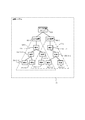
- the communication system 10 includes one aggregation device 400, a plurality of hierarchically configured terminals 300, and one data collection server 101.
- m is a hierarchy and n is a serial number in the same hierarchy.
- the hierarchy refers to the number of hops to the aggregation device 400. For example, “300-11” indicates that it is the first terminal 300 in the first layer, and “300-34” indicates that it is the fourth terminal 300 in the third layer. If the hierarchy position is not particularly distinguished, the terminal 300 may be called.
- a terminal 300-11 and a terminal 300-12 located in the first hierarchy are connected immediately below the aggregation device 400.
- a terminal 300-21 and a terminal 300-22 located in the second hierarchy are connected.
- a terminal 300-31 and a terminal 300-32 are connected.
- a terminal 300-33 located in the third hierarchy is connected.
- a terminal 300-23 and a terminal 300-24 located in the second hierarchy are connected.
- a terminal 300-34 and a terminal 300-35 located in the third hierarchy are connected.
- the data collected from each terminal 300 is transmitted to the data collection server 101 via the aggregation device 400 and stored in the data collection server 101.
- a tree-structure topology in which terminals 300 are connected in a form branched from a root aggregation device 400 will be described as an example.
- a communication system is configured by two aggregation devices 400-1 and 400-2. Not limited to this, a communication system including three or more aggregation devices 400 may be used.
- the communication system 20 includes an aggregation device 400-1 and an aggregation device 400-2, a plurality of hierarchically configured terminals 300, and at least one data collection server 101. Data collected from the terminal 300 is transmitted to the data collection server 101 via the aggregation device 400.
- the aggregation device 400-o and o of the terminal 300-mn-o are network serial numbers.
- the network formed by the aggregation device 400-1 is distinguished from the first network CN1
- the network formed by the aggregation device 400-2 is distinguished from the second network CN2.
- the devices having “1” at the end of the code indicate that they belong to the first network CN1 formed by the aggregation device 400-1.
- the aggregation devices 400-1 forming the first network CN1 are connected to the terminals 300-11-1, 300-21-1, 300-22-1, 300-31-1, 300-32-1, 300.
- a total of six terminals 300 of -33-1 are accommodated.
- the aggregation device 400-2 that forms the second network CN2 accommodates a total of four terminals 300 of terminals 300-11-2, 300-21-2, 300-31-2, and 300-32-2. Yes.
- the networks CN1 and CN2 are separated from each other by using different communication channels.
- the terminals 300 belonging to one network the terminal 300 belonging to the other network or the terminal located in the reach of packets transmitted by the aggregation device 400 can be switched to the communication channel used in the other network. , You can join the other network.
- the terminals 300-22-1 and 300-33-1 are within the packet reachable range of the second network CN2. Accordingly, the terminals 300-22-1 and 300-33-1 can be switched from the first communication network CN1 to the second network CN2. Since the terminal 300-31-2 belonging to the second network CN2 is within the packet reach range of the first communication network CN1, it can be switched to the first network CN1.
- the terminal 300 is an embedded device having a communication function with the aggregation device 400 or another terminal 300.
- Terminal 300 can also be referred to as a wireless communication device.
- the terminal 300 acquires data from an installation destination device (for example, a power meter), stores the data in a packet, and transmits the data to the aggregation device.
- an installation destination device for example, a power meter
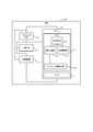
- the terminal 300 includes, for example, a microcomputer (microcomputer in the figure) 301, a clock generation circuit 308, a power supply circuit 309, and a transmission / reception circuit 310.
- the microcomputer 301 includes a ROM (Read Only Memory) 302 and a RAM (Random Access Memory) 307, for example.
- the microcomputer 301 is connected to a clock generation circuit 308, a power supply circuit 309, and a transmission / reception circuit 310.
- the ROM 302 is a storage device including a read-only semiconductor memory.
- the ROM 302 includes, for example, a central control unit 303, a communication processing unit 304, a route management unit 305, and a network switching control unit 306.
- the ROM 302 is connected to the RAM 307.
- the central control unit 303 controls execution of programs in the ROM 302.
- the central control unit 303 is connected to the communication processing unit 304 and the route management unit 305.
- the communication processing unit 304 is in charge of transmission / reception processing with other devices (aggregation device, terminal). Specifically, the communication processing unit 304 performs packet assembly processing such as designating a transmission destination when transmitting, for example. The communication processing unit 304 performs packet analysis processing such as determination of whether or not the packet is addressed to the own terminal when receiving.
- the communication processing unit 304 is connected to the central control unit 303 and the network switching control unit 306.
- the route management unit 305 manages a route in communication between terminals in the network.
- the route management unit 305 is connected to the central control unit 303.
- the RAM 307 is a storage device such as a rewritable semiconductor memory element.
- the RAM 307 is used as a transmission / reception buffer for communication.
- the RAM 307 is connected to the ROM 302.
- the clock generation circuit 308 generates a clock used by the microcomputer 301 and the transmission / reception circuit 310.
- the clock generation circuit 308 is connected to the power supply circuit 309, the microcomputer 301, and the transmission / reception circuit 310.
- the power supply circuit 309 is connected to the clock generation circuit 308, the microcomputer 301, and the transmission / reception circuit 310, and supplies necessary power to these circuits.
- the transmission / reception circuit 310 transmits and receives signals.
- the transmission / reception circuit 310 is connected to the clock generation circuit 308, the power supply circuit 309, and the microcomputer 301.
- the RF peripheral circuit corresponds to the transmission / reception circuit 310.
- the network switching control unit 306 determines whether or not to perform network switching according to a process described later. Note that the terminal 300 does not have to be configured as an embedded device, and may be configured as an independent device.
- the aggregation device 400 communicates with the terminal 300 and the data collection server 101 to collect data from the terminal 300 and the like.
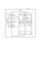
- the aggregation device 400 includes, for example, a microcomputer 401, a clock generation circuit 408, a power supply circuit 409, and a transmission / reception circuit 410.
- the microcomputer 401 includes a ROM 402 and a RAM 407.
- the microcomputer 401 is connected to the clock generation circuit 408, the power supply circuit 409, and the transmission / reception circuit 410.
- the ROM 402 includes a central control unit 403, a communication processing unit 404, and a route management unit 405.
- the hardware configuration of the aggregation device 400 is the same as that of the terminal 300 except that the network switching control unit 306 is not installed.
- the aggregation device 400 may include an external network connection circuit when a function for using an external network such as Ethernet (registered trademark), WiFi (registered trademark), an optical line, or a telephone network is necessary.
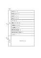
- a packet 500 includes a header 501 and a payload 502.
- the header 501 includes, for example, a destination address 503, a final destination address 504, a transmission source address 505, a transmission source address 506, a packet ID 507, a network ID 508 to which the user belongs, a used communication channel 509, an aggregation device address 510, and a network to which the mail belongs.
- the configuration of the header 501 is not limited to the above. For example, if fields such as packet length and TTL (Time To Live) are necessary, they may be added to the header 501 as appropriate. That is, any header configuration may be used as long as it includes fields equivalent to the destination address 503 to the path cost 514, and the header configuration is not limited to that shown in FIG.
- the header configuration may be a header including a MAC header and an IP header.
- the destination address 503 is a field in which the address or ID of the destination in communication between links is described.
- the identifier of the terminal such as an address or ID described in this field is made to conform to the method adopted in the communication system. It may be an IP address or a MAC address, or the ID may be used if it is identified by a unique ID.
- an address or ID indicating flooding is written in the destination address 503. For example, when describing by MAC address, it corresponds to "FF: FF: FF: FF: FF: FF".
- the final destination address 504 is a field that describes the address or ID of the final destination of the packet. For example, when data collected by the terminal 300 is transmitted to the aggregation device 400, the address or ID of the aggregation device 400 is described in the final destination address 504.
- the transmission source address 505 is a field that describes the address or ID of the terminal 300 that relayed the packet. When the terminal 300 serving as the transmission source transmits, the address or ID of the transmission source terminal is described in the transmission source address 505.
- the source address 506 is a field that describes the address or ID of the source terminal of the packet.
- Packet ID 507 is a field that describes an ID for use in packet identification.
- the packet ID 507 is described by the source terminal. For example, a sequence number used for the IP header is used as the packet ID.
- the packet is discarded.
- the affiliated network ID 508 is a field that describes an ID for identifying the network to which the terminal 300 described in the transmission source address 505 belongs.
- the identifier for identifying the network is not limited to a specific format, and is based on a method adopted in the communication system. For example, as described in FIG. 2, if the first network CN1 and the second network CN2 are identified from the network, “1” or “2” is described in the field 508 (“0” or “ 1 ”may be used. By referring to this field 508, the network to which the transmission source terminal belongs can be identified.
- the used communication channel 509 is a field for describing a communication channel used in the network to which the terminal 300 described in the transmission source address 505 belongs.
- the terminal 300 may receive, from the terminal 300 or the aggregation device 400 belonging to another network, a packet in which the belonging network ID 508 different from the ID of the network to which the terminal belongs is described. At this time, the terminal 300 can grasp the communication channels used in other networks by referring to the communication channels described in this field 509.
- the aggregation device address 510 is a field that describes the address or ID of the aggregation device 400 that forms the network to which the terminal described in the transmission source address 505 belongs. By referring to this field 510, it is possible to grasp the address or ID of the aggregation device 400 forming another network as well as the communication channel, and to transmit data or the like to an appropriate aggregation device 400 even after network switching. Can do.
- the number of terminals 511 accommodated in the network to which the user belongs is a field that describes the number of accommodated terminals under the aggregation device described in the aggregation device address 510.
- the information on the number of accommodations under the aggregation device can be shared between terminals or updated as appropriate.
- Each terminal 300 can determine whether or not the number of accommodated networks exceeds a threshold by referring to this field 511.
- the aggregated unit 400 may periodically notify the number of accommodated units to the terminal 300 as necessary. In this case, the accommodated number stored in each terminal in the network is periodically updated with the accommodated number notified from the aggregation device 400.
- the transmission source terminal layer number 512 describes the number of terminal layers described in the transmission source address 505. Specifically, when the terminal 300-21-1 in FIG. 2 relays a packet, the packet is transferred with a value of “2” written in the field of the layer number 512 of the transmission source terminal. The terminal that has received the packet uses the number of layers 512 of the transmission source terminal to grasp the number of layers of the transmission source terminal or the number of layers of the transmission source terminal. Specifically, the communication processing unit 304 analyzes the received packet and confirms the field number field 512 of the source terminal.
- the terminal 300 updates the number of layers by referring to a field 512 of a packet received from a neighboring terminal when the number of layers in which the terminal is located changes due to a change in the network topology.
- Rank_Max is provided for the number of hierarchies in the communication system, by referring to the field 512, it is also possible to exclude terminals whose hierarchies are set to Rank_Max from the parent terminal candidates. If there is no upper limit on the number of hierarchies, or if control based on the number of hierarchies is not performed, this field 512 may be omitted.
- the number of terminals 513 under the transmission source terminal is a field that describes the total number of sub-terminals connected to the terminal described in the transmission source address 505.
- the child terminal includes a grandchild terminal and the like subordinate to the child terminal. Each terminal, when receiving a packet from the child terminal, refers to this field 513 and records the number of terminals under the child terminal in the parent-child relationship table 700 described later.
- the terminal 300 can calculate the total number of all child terminals (including grandchild terminals, etc.) connected to the own terminal by adding the number of child terminals connected to the own terminal and the number of terminals under each child terminal. .
- the terminals connected to the terminal 300 are also switched together. Therefore, the terminal 300 needs to always know how many terminals are connected to its own terminal.
- the terminal 300 updates the accommodation number, and this field In 513, the updated number of accommodation is described.
- the terminal 300 does not need to manage the number of other terminals connected to the parent terminal that is the connection destination of the terminal.
- the path cost 514 is a field that describes an end-to-end path cost from the terminal 300 described in the transmission source address 505 to the aggregation device 400 described in the aggregation device address 510.
- the path cost is an index indicating end-to-end communication quality from the terminal 300 to the aggregation device 400.
- the path cost only needs to satisfy the relationship that “the path cost is lower as communication quality is better and not negative,” and the calculation method is not particularly limited.
- the path cost can be calculated based on the link quality calculated from the received radio wave intensity and / or the number of hierarchical levels of the terminal.
- the terminal 300 can confirm the path cost from the parent terminal to the aggregation device 400 by referring to this field 514. Then, the terminal 300 can calculate the path cost from the own terminal to the aggregation device 400 based on the path cost from the parent terminal to the aggregation device 400, the link quality between the own terminal and the parent terminal, and the like. it can.
- the terminal 300 when the terminal 300 receives a packet from a terminal belonging to another network different from the network to which the terminal belongs, for example, the terminal 300 switches the terminal having the lowest path cost described in this field 514 to another network. It is stored as a candidate for the parent terminal that becomes the connection destination.
- a method for the terminal 300 to receive a packet from another network will be described.
- the “predetermined information” includes the number of terminals 511 accommodated by the network to which the network belongs, the number of hierarchical levels 512 of the transmission source terminal, the number of terminals 513 subordinate to the transmission source terminal, and the path cost 514.
- the predetermined information is stored in a predetermined control packet and transmitted between terminals.
- each terminal 300 has a path cost to an aggregation device that forms another network, and You can grasp the number of units accommodated.
- each terminal 300 appropriately switches between reception of a packet from the network to which the terminal belongs and switching of reception of a packet from another network by switching communication channels, so that an aggregation device that forms another network can be used. You can grasp the pass cost and the number of units accommodated.
- the terminal 300 calculates the path cost between the aggregation device 400 forming the switching destination network and the own terminal based on the link quality between the own terminal and the parent terminal candidate in the other network. To do.
- the terminal 300 records the calculated path cost in a network management table 600 to be described later in order to use it for network switching control for leveling the number of accommodated units.
- Payload 502 stores application data 515.
- the application data 515 is data collected by the terminal 300.
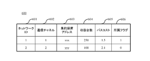
- Each terminal 300 uses the network management table 600 shown in FIG. 6 to manage information about the network to which the terminal belongs and information about other networks that can be switching destination candidates.
- the terminal 300 When the terminal 300 receives the packet 500 from the terminal 300 or the aggregation device 400 belonging to another network different from the network to which the terminal belongs, the terminal 300 refers to each field of the header 501 of the received packet, and information about the other network Are recorded in the network management table 600 or updated.
- the network management table 600 manages, for example, a network ID 601, a communication channel 602, an aggregation device address 603, an accommodation number 604, a path cost 605, and an affiliation flag 606.
- the network ID 601 is a field that describes an ID for identifying each network. In the example of FIG. 2, “1” is described for the first network CN1, and “2” is described for the second network CN2.
- the communication channel 602 is a field that describes a communication channel used in the network specified by the network ID 601.
- the aggregation device address 603 is a field that describes the address or ID of the aggregation device 400 that forms the network specified by the network ID 601.
- the accommodation number 604 is a field that describes the number of accommodation terminals under the aggregation device specified by the aggregation device address 603.
- the terminal 300 receives a packet from another terminal, the terminal 300 refers to the field of the number of accommodated networks 511 to confirm the number of accommodated networks in the network to which the other terminal belongs, and updates the value of the accommodated number 604.
- the path cost 605 is a field that describes the path cost from the own terminal to the aggregation device 400 specified by the aggregation device address 603. As described above, the terminal 300 determines the path cost from the parent terminal to the aggregation device and the link quality between the own terminal and the parent terminal as to the path cost to the aggregation device 400 forming the network to which the terminal belongs. Calculated in the field 605.
- a method for calculating a path cost to another aggregation device 400 that forms a network other than the affiliated network will be described.
- the terminal 300 is connected to the parent terminal candidate when switching to another network.
- the parent terminal candidate holds the path cost from the parent terminal candidate to another aggregation device.
- the terminal 300 calculates the path cost from the own terminal to the aggregation device based on the path cost from the parent terminal candidate to the other aggregation device, the link quality between the own terminal and the parent terminal candidate, and the like. It describes.
- the affiliation flag 606 is a flag field for identifying the network to which the own terminal currently belongs.
- the terminal 300 sets the belonging flag 606 of the network to which the terminal belongs to “1”, and sets “0” for the belonging flag 606 of other networks.
- the configuration of the network management table 600 is not limited to that shown in FIG. If there is information that each terminal should hold in the network management table 600, a field may be added as appropriate. Even if the network is registered in the network management table 600, if a packet cannot be received from a terminal or aggregation device belonging to the network for a long period of time, it is determined that the network has become unusable, and the network management Information may be deleted from the table 600.
- Each terminal uses the parent-child relationship table 700 in FIG. 7 to manage information about a parent terminal and a child terminal connected to its own terminal and information about a parent terminal candidate connected when switching to another network.
- the parent-child relationship table 700 manages, for example, a parent-child identification field 701, a terminal address 702, a belonging network ID 703, the number of subordinate terminals 704, and the number of layers 705 in association with each other.
- the terminal 300 When a new child terminal connects to its own terminal, the terminal 300 adds information on the child terminal to the parent-child relationship table 700. When the child terminal connected so far switches the connection destination to a parent terminal other than the terminal itself, the terminal 300 deletes the information on the child terminal from the parent-child relationship table 700. When the terminal 300 receives a packet from another terminal, the terminal 300 refers to each field of the header 501 of the received packet and records or updates information regarding the other terminal in the parent-child relationship table 700.
- the parent / child identification field 701 is a field for identifying whether the target terminal is a parent terminal or a child terminal.
- the parent terminal is identified as “P” and the child terminal is identified as “C”.
- the description format of the field 701 is not limited to the description format illustrated in FIG. 7 as long as the parent terminal and the child terminal can be distinguished.
- the terminal address 702 is a field that describes an address or ID for identifying the target terminal.
- the affiliated network ID 703 is a field that describes the ID of the network to which the terminal identified by the terminal address 702 belongs.
- the number of subordinate terminals 704 is a field that describes the total number of child terminals (including descendants below the grandchild terminal) connected to the terminal specified by the terminal address 702. As described above, the terminal 300 can calculate the total number of all the child terminals connected to the own terminal by adding the number of child terminals connected to the own terminal and the value of the field 704 in each child terminal. In the table 700 of FIG. 7, the number of terminals connected to the parent terminal and the parent terminal candidates is managed, but the number of terminals is not necessarily managed.
- the number of layers 705 is a field that describes the number of layers in which the terminal specified by the terminal address 702 is located in the network specified by the affiliated network ID 703.
- the parent-child relationship table 700 is not limited to the configuration shown in FIG. In addition to the fields shown in FIG. 7, when there is information that each terminal should hold in the parent-child relationship table 700, fields may be added as appropriate.
- the parent-child identification field 701 When a plurality of parent terminals and a plurality of parent terminal candidates are registered in the parent-child identification field 701, it is described so that the priority order between the actual parent terminal and the parent terminal candidates can be identified. For example, a field for describing the priority order is added to the table 700, or the priority name such as “P1”, “P2”, “P3” is included in the parent / child identification field 701 in a format including the identification name. That's fine.
- terminal 300 cannot receive a packet from a parent terminal candidate for a long period of time, it is determined that the terminal 300 cannot be connected to the parent terminal candidate, and information related to the parent terminal candidate is deleted from parent-child relationship table 700. Also good.
- the procedure from when the terminal 300 detects that the number of accommodations under the aggregation device has exceeded the threshold to when the network is switched will be described.
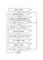
- the terminal 300 determines that network switching is necessary, and whether or not the own terminal performs network switching according to the process of FIG. To decide.
- step S101 the terminal 300 detects that the accommodated number C1 of the aggregation devices 400 forming the network to which the terminal belongs has exceeded a predetermined threshold Thc.
- Step S101 is an example of a “detection unit”.
- the terminal 300 uses the communication processing unit 304 to analyze the field of the accommodated number 511 in the affiliated network of the packet received from the neighboring terminal or the aggregation device 400, thereby confirming whether the accommodated number C1 exceeds the threshold Thc.
- the process proceeds to step S102.
- the threshold number Thc of the accommodation number for each network can be set automatically or manually as a parameter.
- the threshold value Thc can be set according to the scale of the communication system, system requirements, communication environment, and the like, for example.
- the threshold Thc When the accommodation number C1 in each aggregation device is biased, the threshold Thc may be set to be low when leveling control of the accommodation number is performed at the earliest possible stage. If the communication system can tolerate a certain degree of bias, the threshold value Thc may be set high. Thus, the threshold value can be appropriately set according to the requirements of the communication system.
- step S102 the terminal 300 refers to the network management table 600 and confirms whether a switching destination network exists. Specifically, the terminal 300 checks whether there is a network in which the affiliation flag 606 of the network management table 600 is set to “0”. The terminal 300 selects, for example, the network having the lowest value described in the field of the path cost 605 as the switching destination network among the networks in which the affiliation flag 606 is set to “0”.
- the terminal 300 Even if the network that is the switching destination candidate exists on the network management table 600, the terminal 300 has a capacity of the network that is the switching destination candidate (that is, the value described in the capacity 604) exceeds the threshold. If it is, it is determined that switching is impossible. If there is a switchable network (S102: YES), the process proceeds to step S103. If there is no switchable network (S102: NO), this process ends.
- step S103 the terminal 300 calculates a waiting time Tw until the network switching process is performed.
- the terminal 300 can calculate the waiting time Tw based on the end-to-end path cost between the aggregation device forming the switching destination network and the terminal itself.
- the standby time Tw is set to be shorter as the terminal has a lower path cost. Therefore, the network switching process can be executed earlier as the terminal has a lower path cost. As a result, it is possible to perform network switching first from a terminal with good communication quality after network switching, that is, from a terminal that can provide a high data collection rate even after network switching.
- the method for calculating the waiting time Tw is not particularly limited as long as the waiting time Tw is shortened as the path cost is lower.
- the information about the number of accommodated networks is shared by sending and receiving packets between terminals. Therefore, it is considered that the timing at which it is detected in step S101 that the accommodated number C1 exceeds the threshold value Thc varies somewhat between terminals. Some terminals can detect relatively quickly, and other terminals detect later.
- the value of the unit time T is set relatively long. As a result, the influence of variations in detection timing is suppressed, and network switching can be started in order from a terminal with a low path cost.
- the unit time T may be set to be sufficiently longer than the time lag when each terminal 300 acquires the latest value of the number C1 of the network to which it belongs.
- step S104 the terminal 300 starts a timer to start the standby time Tw calculated in step S103.
- step S105 the terminal 300 determines whether the standby time Tw has elapsed.
- the process proceeds to step S106.
- the standby time Tw remains (S105: NO)
- the process proceeds to step S111.
- step S106 when the terminal 300 and the child terminal under its own terminal switch the network together, the terminal 300 confirms whether the accommodation number C1 of the switching destination network does not exceed the threshold Thc.
- the terminal 300 adds one to the total of the total number N of child terminals under its own terminal obtained from the parent-child relationship table 700 and the accommodated number C1 of the switching destination network recorded in the network management table 600 to switch the network. Calculate the number of units accommodated later.
- the terminal 300 confirms whether the calculated accommodated number C1 is less than the threshold value Thc (S106).
- Thc the threshold Thc for the number of units accommodated in each network is described as being set equal, but the threshold Thc can be set to a different value for each network.
- the terminal 300 determines that the network switching of the own terminal and the subordinate child terminals is possible. Then, the process proceeds to step S107.
- step S107 the terminal 300 determines the accommodation number C1 of the switching source network (that is, the network to which the own terminal has belonged) after the own terminal and all the child terminals under its own terminal perform the network switching. Notify other terminals belonging to the switching source network by flooding.
- the switching source network that is, the network to which the own terminal has belonged
- the terminal 300 uses the value obtained by subtracting (N + 1) calculated in step S106 from the accommodated number C1old of the switching source network recorded in the network management table 600 as the accommodated number C1new after the network switching. Notice.
- the capacity of the switching source network before the network switching is indicated as C1old, and the capacity of the switching source network after the network switching is indicated as C1new.
- the terminal 300 notifying the new accommodation number C1new includes an address or ID indicating flooding in the destination address 503 and the final destination address 504 of the packet 500 (“FF: FF: FF: FF: FF” when expressed by a MAC address). : FF ").
- the terminal 300 notifying the new accommodation number C1new, the source address 505 and the source address 506, the address or ID of the own terminal, the packet ID unique to the packet ID 507, and the belonging network ID 508 to the switching source network Switch the communication channel used in the switching source network to the used communication channel 509, the address or ID of the aggregation device forming the switching source network to the aggregation device address 510, and switch the network to the accommodated number 511 in the affiliated network
- the capacity C1new of the subsequent switching source network is set, the number of hierarchical levels of the transmission source terminal is set to 512, the number of hierarchical levels of the own terminal in the switching source network, and the total number of child terminals connected to the own terminal is set to the number of terminals 513 under the transmission source terminal.
- Add own terminal and switching source network to path cost 514 The path cost between the aggregation device 400 formed to generate a packet describing respectively, to the neighboring terminal the packet in flooding (S107). Packet assembly and transmission will be described
- each terminal remaining in the switching source network can quickly grasp the accommodation number C1new after the other terminal switches the network.
- step S115 the network switching process can be stopped when it is detected that the capacity C1new of the belonging network is equal to or less than the threshold value Thc. Therefore, when the execution of the network switching process is decided, the terminal that performs the network switching is notified of the latest accommodation number C1 from the terminal that performs the network switching, thereby suppressing the network switching more than necessary. Can do.
- step S107 the terminal 300 proceeds to step S108.
- step S108 the terminal 300 notifies the child terminal connected to the terminal itself of the communication channel to be switched to.
- the terminal 300 generates the packet 500 as follows, and transmits the generated packet to all the child terminals under its own terminal by unicast or multicast.
- a method of creating a packet for notifying the switching destination communication channel will be described.
- the address or ID of the child terminal is described.
- the transmission source address 505 and the transmission source address 506 the address or ID of the own terminal is described.
- the packet ID 507 describes a unique packet ID.
- the belonging network ID 508 describes the ID of the switching destination network.
- the used communication channel 509 describes a communication channel used in the switching destination network.
- the aggregation device address 510 describes the address or ID of the aggregation device that forms the switching destination network.
- the accommodated number 511 in the affiliation network describes the accommodated number of the switching destination network after switching calculated in step S106.
- the hierarchy number 512 of the transmission source terminal describes the number of hierarchy of the own terminal in the switching destination network (calculated from the information of the parent terminal candidate in the switching destination network described in the parent-child management table 700).
- the path cost 514 describes the path cost between the terminal itself and the aggregation device that forms the switching destination network. Assume that the assembly and transmission of packets in this process follow the procedure described in FIG.
- step S112 which will be described later, a packet for notifying a communication channel or the like used in the switching destination network is also transferred to a terminal (eg, grandchild terminal) below the child terminal, and reaches every corner of the terminal group to be switched.
- a terminal eg, grandchild terminal
- the terminal 300 can notify the switching of the network, the information of the switching destination network, and the used communication channel to a series of terminals connected to the terminal 300.
- step S109 the terminal 300 performs switching to the switching destination network.
- An example of the network switching process will be described later with reference to FIG. When this process ends, the process proceeds to step S110.
- step S110 the terminal 300 resets the standby time Tw started in step S104. For example, the terminal 300 resets after stopping the timer for measuring progress of the waiting time Tw. After step S110 is completed, the flowchart shown in FIG. 8 ends.
- step S111 the terminal 300 confirms whether a communication channel switching notification (S108) has been received from the parent terminal to which the terminal 300 is connected. Specifically, terminal 300 confirms whether the packet generated in step S108 of the parent terminal has been received or whether the packet transferred by the parent terminal in step S112, which will be described later, has been received.
- S108 a communication channel switching notification
- the terminal 300 analyzes the received packet by the communication processing unit 304 to confirm whether the communication channel switching notification has been received.
- the address or ID of the parent terminal is described in the field of the source address 505, and the network ID 508, the used communication channel 509, and the aggregation device address 510 contain different information from the network to which the terminal 300 belongs.
- it is determined that the received packet is a communication channel switching notification from the parent terminal.
- the terminal 300 determines that the communication channel switching notification has been received from the parent terminal (S111: YES)
- the terminal 300 proceeds to step S112.
- the terminal 300 proceeds to step S113.
- step S112 the terminal 300 transfers the packet received from the parent terminal in step S111 to the child terminal connected to the own terminal.
- the terminal 300 copies the contents of the header 501 and payload 502 of the packet received in step S111, rewrites some fields of the header 501, creates a transfer packet, and transmits the transfer packet to each child terminal. Send by cast or multicast.
- the address or ID of the child terminal is described.
- the transmission source address 505 the address or ID of the own terminal is described.
- the source terminal layer number 512 the number of layers of the own terminal recalculated from the number of layers described in the packet received in step S111 (that is, the number of layers of the own terminal in the switching destination network) is described.
- the number of terminals 513 under the transmission source terminal the total number of terminals connected to the own terminal is described.
- the path cost 514 is rewritten to the path cost recalculated from the path cost described in the packet received in step S111 (that is, the path cost to the aggregation device forming the switching destination network).
- step S112 Assume that the packet assembly and transmission in step S112 follows the procedure shown in FIG. After step S112 is completed, the process proceeds to step S109. If there is no child terminal connected to the terminal 300, no processing is performed in step S112, and the process proceeds to step S109.
- step S113 If the terminal 300 has not received a communication channel switching notification from the parent terminal before the waiting time Tw has expired (S111: NO), the process proceeds to step S113.
- step S113 the terminal 300 confirms whether or not the accommodation capacity C1 of the network to which the terminal belongs is updated.
- the terminal 300 determines whether another terminal that performs network switching has received the update information (C1new) flooded in step S107.
- the update information of the accommodated number may be received directly from a terminal that performs network switching, or may be received from a terminal that performs network switching via another terminal (relay terminal).
- the terminal 300 When the terminal 300 receives the packet in which the update information related to the accommodation number is described (S113: YES), the terminal 300 updates the accommodation number information in the network management table 600 and proceeds to step S114. If the terminal 300 has not received the update information (S113: NO), the process returns to step S105.
- step S114 the terminal 300 transfers the packet received in step S113 to the neighboring terminal by flooding.
- the terminal 300 generates the transfer packet by copying the contents of the header 501 and the payload 502 of the packet received in step S113 and rewriting a partial field of the header 501.
- the terminal 300 transmits the transfer packet to the neighboring terminal by flooding.
- the transmission source address 505 the address or ID of the own terminal is described.
- the number of layers 512 of the transmission source terminal describes the number of layers of the own terminal.
- the number of terminals 513 under the transmission source terminal the total number of terminals connected to the own terminal is described.
- the path cost 514 is rewritten to the path cost from the aggregation device forming the affiliated network to the own terminal.
- step S114 The packet assembly and transmission in step S114 follows the procedure shown in FIG. However, if the same packet having the same source address 506 and packet ID 507 is received, the packet is discarded as described above. Therefore, when the packet received in step S113 is a duplicate packet, the transfer process is not performed in step S114. After step S114 is completed, the process proceeds to step S115.
- step S115 the terminal 300 confirms whether or not the accommodated number C1 is equal to or less than the threshold value Thc as a result of updating the accommodated number of the belonging network in step S113.
- the process proceeds to step S110, and when the threshold value Thc is still exceeded (S115: NO), the process returns to step S105.
- steps S102 to S108 are examples of a “switching determination unit”.
- Step S109 (the flowchart of FIG. 11) is an example of a “switching execution unit”.
- each terminal 300 subordinate to the aggregation device performs network switching control according to the flowchart of FIG.
- Network switching at each terminal 300 is executed when a predetermined standby time Tw determined from communication quality (path cost) in the switching destination network has elapsed. Therefore, network switching can be performed in order from the terminal having good communication quality that can be used in the switching destination network.
- Tw standby time
- the terminal 300 controls the timing for performing network switching according to the standby time Tw that is autonomously calculated based on the path cost with the aggregation device 400 that forms the switching destination network. Accordingly, leveling control can be realized by autonomous distributed control between terminals without a management device for managing information on each terminal.
- FIG. 9 is a flowchart showing a procedure in which a terminal serving as a transmission source transmits a packet to the network.
- the terminal 300 follows the processing flow of FIG. 9 when the terminal 300 transmits a packet with the terminal serving as the transmission source.
- step S121 the terminal 300 stores application data to be transmitted in the payload. For example, when the terminal 300 wants to transmit the collected data, the terminal 300 describes the contents of the data in the application data field 515 of the payload 502.
- step S122 the terminal 300 describes necessary information in the fields 503 to 514 of the header 501, and assembles the packet 500 by attaching the header 501 to the payload 502.
- the terminal 300 When providing a field such as TTL (Time (To ⁇ ⁇ ⁇ Live) in addition to the header fields 503 to 514 shown in FIG. 5, the terminal 300 describes necessary information in the header 501 before proceeding to Step S123. Note that the processing related to packet assembly up to this point is performed by the communication processing unit 304 shown in FIG.
- step S123 the packet assembled up to step S122 is transmitted. This transmission processing is performed by the transmission / reception circuit 310 of FIG. 3, and the flowchart of FIG. 9 ends after transmission.
- FIG. 10 is a flowchart showing a transmission procedure when the terminal 300 transfers a packet.
- the terminal 300 transfers a packet received from the source terminal or another relay terminal, the terminal 300 follows the process of FIG.
- step S131 the terminal 300 copies the application data of the received packet to be transferred to the application data field 515 of the payload 502 of the transfer packet.
- the transfer packet is a packet transferred from the terminal 300 toward another terminal or the aggregation device.
- step S132 the terminal 300 copies the header of the received packet to be transferred, overwrites the field that needs to be rewritten in the header field of the transfer packet, and assembles the transfer packet.
- the terminal 300 copies or overwrites necessary information in the header before proceeding to step S133. For example, if a TTL field is provided, the terminal 300 decrements and updates the TTL value in step S132.
- the processing related to the packet assembly so far is performed by the communication processing unit 304 in FIG.
- step S133 the terminal 300 transmits the packet assembled up to step S132 to the network.
- This transmission processing is performed by the transmission / reception circuit 310 of FIG.
- the flowchart of FIG. 10 ends.
- step S109 in FIG. 8 corresponds to the process in FIG.
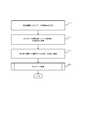
- step S141 the terminal 300 switches the communication channel used by the terminal 300 to the communication channel used in the switching destination network.
- the terminal 300 refers to the communication channel used in the desired switching destination network from the field of the communication channel 602 in the network management table 600, and switches to that communication channel. After this process, the process proceeds to step S142.
- step S142 the terminal 300 transmits a packet requesting terminal registration to the aggregation device forming the switching destination network via the parent terminal connected to the terminal itself in the switching destination network.
- the terminal 300 that intends to newly enter the switching destination network notifies the parent terminal that the own terminal is connected as a child terminal, and notifies the aggregation device that the own terminal has entered the switching destination network. . Furthermore, the terminal 300 that is going to newly enter the switching destination communication network requests registration of the terminal, so that the latest accommodated number after the terminal joins the switching destination network is determined for each terminal in the switching destination network. Can be notified early.
- the parent terminal to which the terminal 300 is connected in the switching destination network refers to a terminal in which the affiliation network ID 703 in the parent / child management table 700 is the ID of the switching destination network and the parent / child identification field 701 indicates that it is a parent. If there are a plurality of parent terminal candidates in the switching destination network, the candidate with the highest priority is the parent terminal.
- the terminal registration request packet transmitted in step S142 is not limited to a specific format. An example in which the terminal 300 to be switched creates a terminal registration request packet according to the packet format of FIG. 5 will be described.
- the final destination address 504 describes the address or ID of the aggregation device that forms the switching destination network.
- the transmission source address 505 and the transmission source address 506 describes the address or ID of the terminal 300.
- the packet ID 507 describes a unique packet ID.
- the belonging network ID 508 describes the ID of the switching destination network.
- the used communication channel 509 describes a communication channel used in the switching destination network.
- the aggregation device address 510 describes the address or ID of the aggregation device that forms the switching destination network.
- the accommodation capacity 511 in the affiliation network describes the accommodation capacity of the switching destination network after switching. The accommodation capacity in the switching destination network is calculated in the same manner as in step S106 in FIG.
- the number of layers 512 of the transmission source terminal describes the number of layers of the terminal 300 in the switching destination network.
- the number of layers of the terminal 300 in the switching destination network can be calculated from the parent terminal information 705 in the switching destination network described in the parent-child management table 700.
- the number of terminals 513 under the transmission source terminal describes the total number of terminals connected to the terminal 300.
- the path cost 514 describes the path cost between the terminal 300 and the aggregation device 400 that forms the switching destination network.
- the aggregating apparatus 400 that has received the terminal registration request packet detects that a new terminal 300 has entered the network formed by the own apparatus 400 by referring to the source address 506 and the affiliated network ID 508 in the packet. After finishing the process of step S142, it progresses to step S143.
- step S143 the terminal 300 receives a response to the terminal registration request packet transmitted in step S142 from the aggregation device 400 of the switching destination network.
- the terminal registration request response packet transmitted by the aggregation device 400 is not limited to a specific format. After receiving this response packet, the process proceeds to step S144.
- the process may return to step S142 and retransmit the terminal registration request packet.
- the terminal 300 may switch to another parent terminal candidate and retransmit the terminal registration request packet.
- the terminal 300 may abandon the network switching, re-switch to the communication channel used in the switching source network, and notify that the own terminal re-enters the switching source network. .
- the terminal 300 that has failed to switch the network again notifies the neighboring terminal of update information related to the number of accommodated switching source networks, and notifies the subordinate child terminals of the switching of the communication channel.
- step S144 the terminal 300 updates the network management table 600 with the information after the network switching.
- the terminal 300 changes the affiliation flag 606 of the switching source network from “1” to “0”, and changes the affiliation flag 606 of the switching destination network from “0” to “1”. After this process is completed, the process proceeds to step S145.
- step S145 the terminal 300 updates the parent-child management table 700 with information after network switching. Since it is assumed that the child terminal also performs network switching together with its own terminal, specifically, the affiliated network ID 703 of the child terminal is rewritten with the ID of the switching destination network, and the terminal under the parent terminal of the switching source and switching destination networks The number 704 is updated to the information after network switching, and the number of child terminal layers 705 is rewritten to a value obtained by adding 1 to the number of own terminal layers in the switching destination network. After this process is finished, the process of the flowchart of FIG. 11 is finished.
- the terminal 300 does not necessarily have to execute the process of step S145 at the timing of the network switching process of the own terminal in FIG.
- the terminal 300 may update the information in the parent-child management table 700 at the timing when it is confirmed that the network switching of the child terminal is successful.
- the terminal 300 can detect that the switching of the child terminal has succeeded by relaying the terminal registration request packet transmitted by the child terminal or the response packet from the aggregation device for the packet.
- this embodiment is configured as described above, the following effects can be obtained.
- information regarding the number of accommodation C1 under the aggregation device is autonomously shared between the terminals, and each terminal autonomously controls the timing of network switching based on the standby time Tw calculated from the path cost. Therefore, in this embodiment, even if there is no management device for managing the information of each terminal, in the autonomous distributed control between the terminals, it is triggered by the fact that the accommodated number C1 exceeds the threshold Thc. The process can be started. As a result, it is possible to perform network switching in order from a terminal having good communication quality that can be used in the switching destination network. Further, when it is detected that the accommodation number C1 is equal to or less than the threshold value Thc, the network switching process is performed. Can be terminated autonomously.
- the present embodiment even when there is a restriction such as a narrow communication band, it is possible to level the number of units accommodated between the aggregation devices.
- the communication band is narrow, it is difficult for each terminal to frequently transmit various information to the management device, and centralized control by the management device is not suitable.
- the number of accommodations in each aggregation device can be leveled without a management device.
- the network topology having the tree structure shown in FIG. 2 has been described as an example.
- the present invention is not limited to this, and the present invention can also be applied to other topologies other than the tree structure. For example, a configuration in which topologies such as a tree structure, a mesh structure, and a star structure are combined may be used.
- a second embodiment will be described with reference to FIGS.
- This embodiment corresponds to a modification of the first embodiment. Therefore, the difference from the first embodiment will be mainly described.
- the number of accommodation units for each aggregation device is leveled by autonomous distributed control between terminals.
- a management device 800 for managing information of each terminal existing in the communication system is provided, and the accommodation number for each aggregation device is leveled by centralized control by the management device 800.
- a communication system configuration and a packet configuration will be described with reference to FIGS.
- the network management table configuration held by each terminal will be described with reference to FIG.
- FIGS. 15 and 16 a description will be given of a packet configuration in the case of notifying information of each terminal to the management device and a packet configuration transmitted when the management device requests network switching to the terminal.
- a network management table configuration and a terminal management table configuration held by the management apparatus will be described with reference to FIGS. 17 and 18.
- network switching control for leveling will be described with reference to FIGS.
- the procedure and the procedure for transferring (FIGS. 9 and 10) are the same as in the first embodiment.
- the procedure for switching the terminal network is the same as in the first embodiment (FIG. 11) except that the network management table 600A of FIG. 14 is used.
- the communication system 30 including a plurality of aggregation devices will be described with reference to FIG.
- the communication system 30 is configured to include two aggregation devices 400-1 and 400-2 (hereinafter referred to as the aggregation device 400 unless otherwise distinguished), but is not limited thereto. Three or more aggregation devices may be included.
- the communication system 30 of the present embodiment is configured in the same manner as the communication system 20 shown in FIG. 2 except that a management apparatus 800 connected to each aggregation apparatus 400 is provided.
- the management device 800 uses the network management table 1700 described later to manage information about the network formed by each aggregation device. Furthermore, the management apparatus 800 manages information on each terminal in the communication system using a terminal management table 1800 described later. Information obtained by each aggregation device receiving a packet from the terminal is transferred to the management device 800. The management apparatus 800 reflects information from each terminal in the network management table 1700 and the terminal management table 1800.
- the management device 800 determines a terminal that performs network switching for leveling of the accommodated devices.
- the data collection server 101 and the management apparatus 800 are shown as separate apparatuses, but instead, the data collection server 101 and the management apparatus 800 may be configured as a single computer. That is, a configuration in which a function as a data collection server and a function as a management apparatus are physically provided in one computer may be employed. A configuration may be adopted in which a plurality of computers are physically linked to operate as if they were one computer, and a data collection server and a management device are mounted on the one computer.
- the configuration of the packet 500A according to the present embodiment will be described with reference to FIG.
- the packet format of FIG. 13 is the same as the packet 500 of FIG. 5 except that there is no field for the number of accommodated units 511 in the affiliated network.
- the packet used in the present embodiment does not need to have a field for the accommodation number 511 in the network to which it belongs.
- the packet format of FIG. 5 can also be used in this embodiment, for example, when the terminal needs to know the number of units accommodated in each network in order to satisfy the application request provided on the communication system. Further, as described in the first embodiment, if other fields such as the packet length and TTL are necessary in addition to the fields described in FIG. 13, they may be added to the header 501.
- the configuration of the network management table 600A held by each terminal will be described with reference to FIG. As described above, in this embodiment, since each terminal does not need to grasp the number of accommodated units for each network, the field of accommodated number 604 is not provided in FIG.
- the network management table 600A shown in FIG. 14 is the same as the network management table 600 shown in FIG. 6 except that the storage capacity field is not provided. However, when a field for the number of accommodated 511 in the belonging network is provided in the header 501 of the packet, a field for the accommodated number 604 may be provided in the network management table 600A.
- fields may be added as appropriate. Even in the network described in the network management table 600A, if a packet cannot be received from a terminal or aggregation device belonging to the network over a long period of time, it is determined that the network has become unusable, and the network management You may delete from table 600A.
- the management apparatus 800 In order for the management apparatus 800 to determine a terminal that should perform network switching in order to equalize the number of units accommodated in each aggregation apparatus, it is desirable that information regarding each terminal can be grasped in real time as much as possible.
- each terminal periodically notifies the management apparatus 800 of information related to its own terminal.
- each terminal does not need to notify the management apparatus 800 of information regarding its own terminal at a specific time and a specific cycle.
- Each terminal can determine the timing for transmitting information related to its own terminal to the management apparatus 800 according to the available communication band or the size of the communication system. For example, each terminal may transmit information related to its own terminal to the management apparatus 800 within a time when the communication band is relatively free.
- a packet 1500 includes a header 1501 and a payload 1502.
- the header 1501 includes, for example, a destination address 1503, a final destination address 1504, a transmission source address 1505, a transmission source address 1506, a packet ID 1507, a belonging network ID 1508, a belonging source path cost 1509, a switching destination candidate network ID 1510, and a switching destination candidate path cost 1511.
- the number of terminals 1512 under the source terminal is provided. However, if fields other than the fields shown in FIG. 15, such as packet length and TTL, are necessary, they may be added to the header as appropriate.
- Destination address 1503, final destination address 1504, source address 1505, source address 1506, and packet ID 1507 are the same as destination address 503, final destination address 504, source address 505, source address 506, and packet ID 507 in FIG. It is.
- the affiliated network ID 1508 is a field that describes the ID of the network to which the terminal described in the source address 1506 belongs.
- the affiliation source path cost 1509 is a field that describes the path cost from the terminal described in the transmission source address 1506 to the aggregation device that forms the network described in the affiliation network ID 1508.
- the switching destination candidate network ID 1510 is a field that describes the ID of the network that can be switched by the terminal described in the source address 1506.
- the terminal serving as the transmission source refers to the network management table 600A and describes the network ID in which “0” is described in the affiliation flag 606.
- the switching destination candidate path cost 1511 is a field that describes the path cost from the terminal described in the source address 1506 to the aggregation device that forms the network described in the switching destination candidate network ID 1510.
- the terminal serving as the transmission source refers to the path cost 605 of the network management table 600A, and describes the network path cost described in the switching destination candidate network ID 1510 in the field 1511.
- the header fields 1510 and 1511 may be expanded to describe a plurality of switching destination candidate network IDs and switching destination candidate path costs.
- each terminal notifies the management apparatus 800 of its own terminal information, if there is a surplus in the number of packets that can be notified, a plurality of switching destination network IDs and path costs are not described in one packet. May be notified to the management apparatus 800 in a separate packet.
- the number of terminals 1512 under the source terminal is a field that describes the total number of terminals below the child terminal (such as grandchild terminal) connected to the terminal described in the source address 1506.
- Predetermined information among the information described in the header 501 by the source terminal is not rewritten by the relay terminal.
- the predetermined information includes the final destination address 1504, the source address 1506, the packet ID 1507, the belonging network ID 1508, the belonging source path cost 1509, the switching destination candidate network ID 1510, the switching destination candidate path cost 1511, and the number of terminals under the source terminal 1512. It is.
- the payload 1502 stores application data 1513 to be transmitted. If there is application data to be periodically notified to the management apparatus 800 other than the information related to the terminal, the application data is stored in the field 1513.
- Each terminal uses the packet in the format of FIG. 13 and the packet in the format of FIG. 15 to notify the management apparatus 800 of information regarding the terminal itself using a common packet, instead of notifying the management apparatus 800. You may be notified.
- the header 501 of the packet format in FIG. 13 includes fields equivalent to the belonging network ID 1508, the belonging source path cost 1509, the switching destination candidate network ID 1510, the switching destination candidate path cost 1511, and the number of terminals 1512 under the source terminal. You may add and use.
- the management apparatus 800 When the management apparatus 800 detects that the number of accommodated terminals of a certain aggregation apparatus 400 exceeds the threshold, the management apparatus 800 determines a terminal to perform network switching according to the process of FIG. 19 described later, and requests a network switching request to the determined terminal. Send.
- the packet 1600 includes a header 1601 and a payload 1602.
- the header 1601 includes a destination address 1603, a final destination address 1604, a transmission source address 1605, a transmission source address 1606, a packet ID 1607, and a switching destination network ID 1608.
- fields such as packet length and TTL may be added to the header.
- Destination address 1603, final destination address 1604, transmission source address 1605, transmission source address 1606, and packet ID 1607 are the same as destination address 503, final destination address 504, transmission source address 505, transmission source address 506, and packet ID 507 in FIG. It is.
- the switching destination network ID 1608 is a field that describes the ID of the switching destination network designated by the management apparatus 800 when the terminal performs network switching.
- the payload 1602 stores application data 1609 to be transmitted.
- the management apparatus 800 requests the terminal to switch the network, if there is application data to be accompanied and notified, it is stored in this field 1609.
- the packet format related to the network switching request has been described separately for the format of FIG. 13 and the format of FIG. 15, but a common format may be used instead.
- a field equivalent to the switching destination network ID 1608 may be added to the header of FIG.
- “ ⁇ 1” may be described at normal time, and the network ID that is the switching destination may be described only when a network switching request is made.
- the configuration of the network management table 1700 held by the management apparatus 800 will be described with reference to FIG.
- the management apparatus 800 uses the network management table 1700 to manage network information formed by each aggregation apparatus 400.
- the management apparatus 800 Since the management apparatus 800 is always connected to each aggregation apparatus, when the information to be managed is updated, the updated contents can be grasped at an early stage. When information about the network is updated, the management apparatus 800 reflects the latest information on the network management table 1700.
- the network management table 1700 shown in FIG. 17 is the same as the network management table 600 held by the terminal described in the first embodiment. It is.
- a field for describing the information may be added to the table 1700.
- the configuration of the terminal management table 1800 held by the management apparatus 800 will be described with reference to FIG.
- the management apparatus 800 uses the terminal management table 1800 to manage information on all terminals in the communication system. Based on the terminal information obtained via each aggregation device, information described in the terminal management table 1800 is updated as appropriate. When the number of accommodated terminals in the aggregation device exceeds the threshold, the contents described in the terminal management table 1800 are referred to in the process of FIG. 19 described later, and a terminal that requests network switching is determined.
- the terminal address 1801 is a field that describes an address or ID for identifying the terminal.
- the affiliation network ID 1802 is a field that describes the ID of the network to which the terminal specified by the terminal address 1801 belongs.
- the number of subordinate terminals 1803 is a field that describes the total number of terminals below and including child terminals (including grandchild terminals) connected to the terminals specified by the terminal address 1801.
- the path cost 1804 of the first network CN1 and the path cost 1805 of the second network CN2 are fields that describe the path cost from the terminal specified by the terminal address 1801 to the aggregation device that forms the corresponding network.
- FIG. 18 shows only fields 1804 and 1805 related to the first network CN1 and the second network CN2 in accordance with the communication system configuration diagram of FIG. Not only this but this field 1804 and 1805 may be provided by the number of the aggregation apparatuses which exist on a communication system. That is, when a communication system is configured by five aggregation devices, five fields relating to the path cost to each aggregation device are provided.
- the initial value of the fields 1804 and 1805 regarding the network path cost is set to “ ⁇ 1”.
- the terminal specified by the terminal address 1801 cannot be switched to a network in which “ ⁇ 1” is set as the path cost.
- the terminals with the terminal addresses “fff” and “ggg” cannot be switched to the second network CN2.
- the aggregation device and the management device When the aggregation device and the management device receive the packet from the terminal, the aggregation device and the management device refer to the field of the affiliation network ID and the switching destination candidate network ID and the corresponding path cost field. Thereby, the aggregation device and the management device collect the path cost to the aggregation device forming the network to which the terminal belongs or the path cost to the aggregation device forming the switching destination candidate network. Information on the obtained path cost is written in the path cost field of the terminal in the terminal management table 1800 as needed.
- the management apparatus 800 detects that the capacity C1 under a certain aggregation apparatus exceeds the threshold Thc, the management apparatus 800 selects a terminal that performs network switching from among the terminals 300 belonging to the network formed by the aggregation apparatus. Request.
- step S201 the management device 800 detects that the accommodation number C1 under the aggregation device has exceeded the threshold value Thc.
- the management device 800 confirms the field of the accommodation number 604 of the network management table 1700 held by itself, and confirms whether the accommodation number C1 of each aggregation device does not exceed the threshold Thc.
- the management apparatus 800 detects that the number of accommodation C1 under a certain aggregation apparatus exceeds the threshold Thc, the management apparatus 800 proceeds to step S202.
- the threshold Thc for the number of accommodated vehicles can be set as a parameter, and can be set according to the scale of the communication system or the communication environment.
- the management apparatus 800 includes a terminal that can be switched to another network among terminals belonging to the network formed by the aggregation apparatus in which it is detected in step S201 that the accommodated number C1 exceeds the threshold Thc. Make sure.
- the management apparatus 800 determines that the terminal can be switched to another network when the following two conditions are satisfied.
- the first condition is that, in the terminal management table 1800, the network ID described in the belonging network ID 1802 and the network ID formed by the aggregation device detected in step S201 are the same.
- the second condition is that a non-negative value is described in the path cost field for a network other than the network formed by the aggregation device detected in step S201.
- step S203 If it is determined that there is a switchable terminal in another network (S202: YES), the process proceeds to step S203. If it is determined that there is no switchable terminal (S202: NO), it is determined that the leveling process cannot be executed, and this flowchart ends.
- step S203 the management apparatus 800 selects a terminal with the lowest path cost from the terminals that are determined to be switchable to another network to the aggregation apparatus that forms the network that is the switching destination candidate.
- the management device 800 refers to each path cost field (1804 or 1805) of the terminal determined to be switchable to another network in step S202 in the terminal management table 1800.
- the management apparatus 800 compares the path cost values in the switching destination network of each terminal, and selects one terminal having the lowest path cost. For the terminal detected in S202, the network that provides the lowest path cost is the switching destination network of the terminal. It progresses to step S204 after the process of step S203.
- step S204 when the terminal selected in step S203 and the child terminal connected to the terminal perform network switching, the management apparatus 800 checks whether the accommodation number C1 of the switching destination network does not exceed the threshold Thc. .
- the management apparatus 800 refers to the field of the number of subordinate terminals 1803 in the terminal management table 1800 and confirms the total number N of each terminal below the child terminal connected to the terminal selected in step S203.
- the management device 800 confirms the field of the accommodation number 604 of the switching destination network in the network management table 1700, and confirms that the threshold Thc is not exceeded even if N + 1 is added to the accommodation number C1.
- the management apparatus 800 determines that the accommodated number C1 in the switching destination network exceeds the threshold Thc when a total of N + 1 terminals including the terminal selected in step S203 and its child terminals perform network switching (S204). : NO), abandon the network switching of the terminal, and return to step S202.
- the terminal that is determined that the accommodated number C1 exceeds the threshold Thc is considered to be non-switchable with respect to the network in the next step S202.
- the process proceeds to step S205.
- step S205 the management apparatus 800 requests the terminal selected in step S203 to switch the network.
- the terminal selected as the switching target may have a plurality of switching destination candidate networks. Therefore, the management apparatus 800 designates the switching destination network ID in the field of the switching destination network ID 1608 of the network switching request packet. After step S205, the process proceeds to step S206.
- step S206 the management apparatus 800 receives a response to the network switching request transmitted in step S205 from the switching target terminal.
- the terminal receives a network switching request packet addressed to itself from the management apparatus, the terminal transmits a response packet to the management apparatus. After receiving the response packet, the process proceeds to step S207.
- step S205 If a response packet cannot be received from the switching target terminal after a lapse of a certain time after transmitting the network switching request packet in step S205, the management apparatus 800 returns to step S205 and retransmits the network switching request. Also good. If the response packet cannot be received even after re-transmission, there is a possibility that network switching cannot be performed due to an abnormality in the terminal. Therefore, the network switching by the terminal selected in S203 may be abandoned and the process may return to step S202.
- step S207 the management apparatus 800 confirms that the terminal selected in step S203 and all the subordinate terminals have performed network switching via the aggregation apparatus that forms the switching destination network.
- each terminal transmits a terminal registration request packet to the aggregation device forming the switching destination network in the network switching processing described in FIG. By confirming whether this terminal registration request packet has arrived at the aggregation device of the switching destination network, it can be determined whether the switching has been completed.
- step S208 Upon confirming completion of network switching by each terminal, the process proceeds to step S208.
- the process may directly proceed to step S208 and subsequent steps, and the table update process or the like may be performed for the terminals for which the terminal registration request packet is obtained.
- step S208 the management apparatus 800 updates information in the network management table 1700 held by the own apparatus.
- the management device 800 subtracts the accommodated number of the switching source network by the number of terminals that have performed network switching in the accommodated number 604 field.
- the management apparatus 800 adds the number of accommodations of the switching destination network by the number of terminals that have performed network switching. After this process, the process proceeds to step S209.
- step S209 the management apparatus 800 updates the information in the terminal management table 1800 held by the own apparatus.
- the management apparatus 800 updates the field of the affiliated network ID 1802 to the ID of the switching destination network for the terminal that has switched the network. After this process, the process proceeds to step S210.
- the number of subordinate terminals changes for the parent terminal connected to the terminal that has switched the network (the parent terminal in the switching destination network).
- Each terminal in the network periodically notifies the management apparatus 800 of terminal information via the aggregation apparatus. Therefore, the management apparatus 800 detects a change in the number of subordinate terminals and reflects it in the terminal management table 1800. Can do.
- the parent terminal whose number of subordinate terminals changes may notify the management apparatus 800 when the number of subordinate terminals changes.
- step S210 the management device 800 confirms whether or not the number C1 of the aggregation devices detected to exceed the threshold in step S201 is equal to or less than the threshold Thc.
- the management device 800 confirms whether the value of the accommodated number 604 after updating the information in the network management table 1700 in step S208 is equal to or less than the threshold value Thc.
- Thc the threshold value
- the leveling of the accommodation number is completed, and the flowchart of FIG.
- the management apparatus 800 continues the leveling process and returns to step S202.
- the management apparatus 800 detects that the number C1 accommodated by the aggregation apparatus has exceeded the threshold Thc, and determines a terminal for performing network switching according to the flowchart of FIG. Therefore, also in the present embodiment, as in the first embodiment, it is possible to perform network switching in order from the terminal with good communication quality that can be used in the switching destination network, and the data collection rate from the terminal is set to a high value. While maintaining, the accommodation number of each aggregation device can be leveled. Further, in this embodiment, since the management of the waiting time Tw described in the first embodiment is not required, the time required for leveling can be shortened compared to the case of the first embodiment.
- the terminal 300 receives a network switching request from the management device 800 will be described.
- the terminal that has received the network switching request from the management apparatus 800 performs processing up to the network switching according to the flowchart of FIG.
- step S221 the terminal 300 receives the network switching request transmitted from the management apparatus to the own terminal. After this process, the process proceeds to step S222.
- step S222 the terminal 300 transmits a response packet to the network switching request packet received in step S221 to the management apparatus.
- the management apparatus 800 can confirm that the network switching request packet has reached the desired terminal by receiving the response packet in step S206 of FIG. After step S222, the process proceeds to step S223.
- step S223 the terminal 300 notifies the subordinate child terminals of the communication channel used in the network designated as the switching destination by the management apparatus.
- the terminal 300 performs network switching together with all the terminals below the child terminals connected to the terminal. Therefore, the terminal 300 needs to notify the child terminal of information related to the switching destination network.
- the process in step S223 is the same as step S108 in FIG. 8 except that the packet to be transmitted conforms to the format in FIG. 13 (that is, does not include information on the number of units accommodated). After step S223, the process proceeds to step S224.
- step S224 the terminal 300 switches from the management device 800 to the network designated as the switching destination.
- the specific process is the same as the flow described in FIG. After step S224, the flowchart of FIG.
- step S143 in FIG. 11 if the response packet from the aggregation device cannot be received, the terminal 300 may transmit a packet indicating that the network cannot be switched to the management device 800.
- the management apparatus 800 receives the packet after step S205, the management apparatus 800 gives up the network switching by the terminal that has notified that the network cannot be switched, and returns to step S202.
- the processing at the child terminal that has received the communication channel switching notification from the parent terminal will be described.
- the child terminal performs processing up to the network switching according to the flowchart of FIG.
- step S231 the child terminal receives a communication channel switching notification.
- a communication channel switching notification There are a plurality of communication channel switching notifications. One of them is a case where the parent terminal receives the packet generated in step S223 of FIG. The other case is when a packet transferred by the parent terminal is received in step S232 described later. After step S231, the process proceeds to step S232.
- step S232 the child terminal transfers the packet received in step S231 (a packet indicating a communication channel switching notification) to the child terminal connected to the own terminal.
- This process is the same as step S112 in FIG. 8 except that the packet to be transmitted follows the format of FIG. 13 (that is, does not include information on the number of units accommodated).
- step S233 the process proceeds to step S233.
- step S233 the child terminal switches the network to the switching destination notified from the parent terminal.
- the child terminal switches the network according to the flow described in FIG. After step S233, the flowchart of FIG.
- a network switching request is transmitted only to the terminal selected in step S203.
- the network switching request may be transmitted not only to the switching target terminal but also to all the child terminals connected to the terminal. good.
- a terminal of a communication system comprising a plurality of aggregation devices for communicating with a plurality of terminals, A communication network having a plurality of predetermined terminals among the plurality of terminals is configured for each of the plurality of aggregation devices, A detecting unit for detecting whether a predetermined condition set in advance is established in the switching source communication network to which the terminal belongs, among the plurality of communication networks; When the establishment of the predetermined condition is detected, based on the communication quality when the own terminal belongs to the switching destination communication network among the plurality of communication networks, a switching determination unit that determines switching of the belonging destination, A switching execution unit that switches the affiliation of the terminal from the switching source communication network to the switching destination communication network according to the determination; A communication system terminal comprising: Expression 2.
- a management device for managing a communication system including a plurality of aggregation devices that communicate with a plurality of terminals, A communication network having a plurality of predetermined terminals among the plurality of terminals is configured for each of the plurality of aggregation devices, An accommodation number indicating the number of terminals accommodated by the plurality of aggregation devices, and a management table for managing the quality of communication paths between the plurality of terminals and the plurality of aggregation devices;
- the switching source aggregation device is formed based on the quality of the communication path described in the table.
- a switching target terminal is selected from the terminals belonging to the switching source communication network, and a switching destination formed by an aggregation device different from the switching source aggregation device is selected for the selected switching target terminal.
- Request to switch to communication network Communication system management device.
Landscapes
- Engineering & Computer Science (AREA)
- Computer Networks & Wireless Communication (AREA)
- Signal Processing (AREA)
- Data Exchanges In Wide-Area Networks (AREA)
Abstract
集約装置配下で通信を担当する端末の数を平準化すること。 複数の集約装置ごとに、複数の端末のうち所定の複数の端末を有する通信ネットワークがそれぞれ構成されている。複数の端末はそれぞれ、自端末の所属する切替元の通信ネットワークにおいて、予め設定される所定の条件が成立したか検知する検知部(S101)と、所定の条件の成立を検知した場合、切替先の通信ネットワークに自端末が所属した場合の通信品質に基づいて、所属先の切替を決定する切替決定部(S102~S109)と、決定に従って自端末の所属先を切替元の通信ネットワークから切替先の通信ネットワークに切り替える切替実行部(S109)と、を備える。
Description
本発明は、通信システムおよび端末の所属先ネットワーク切替方法に関する。
AMI(Advanced Metering Infrastructure)またはセンサネットワーク等の分野では、ある集約装置の配下に複数の端末を収容し、これら複数の端末からデータを収集する形態を持つ通信ネットワークが構築される。
しかし、現実的には、1台の集約装置に収容可能な端末台数には上限がある。集約装置の収容端末台数が上限値に達した場合、新たな端末は、その集約装置の配下のネットワークに新規参入することができない。
端末の新規参入を実現するためには、集約装置の配下に存在する既存の端末の何れかを他の集約装置配下の通信ネットワークに切り替えさせる必要がある。従って、ネットワーク切替が完了するまでの間、無駄な待ち時間が発生する。
さらに、例えば、第1のネットワークを構成する第1の集約装置が故障した場合、故障した第1の集約装置に収容されていた端末が、一斉に、隣接する第2の集約装置配下の第2のネットワークへ新規参入する可能性もある。
しかしもしも、第2の集約装置の収容端末台数が上限値に達していた場合、まず最初に、第2のネットワークに所属している既存端末の多くを、隣接する第3のネットワークに移して、第2の集約装置の収容端末台数を上限値以下にする必要がある。その後に、故障した第1ネットワークに属する端末を、第2ネットワークに新規参入させる。このため、ネットワーク切替が行われる端末の数が膨大となり、全端末の切替が完了するまでに長い時間を要する。従って、端末との通信が長期に亘って中断し、AMIまたはセンサネットワークのようなシステムの信頼性および使い勝手が低下する。
第2の集約装置の収容端末台数が上限値に達していない場合であっても、集約装置間で端末集約台数に偏りが生じていては、不具合を生じるおそれがある。すなわち、収容端末台数の多い集約装置の負荷(通信負荷など)が増大し、高負荷の集約装置の配下のネットワークにおいてスループットが低下するおそれがある。
CSMA/CA(Carrier Sense Multiple Access/Collision Avoidance)のみで端末間の送信機会の競合を回避する通信システムでは、収容端末台数が多いネットワークであるほど、端末間で競合が頻繁に発生するため、大幅なスループットの低下を招く恐れがある。
従って、これらの問題点を鑑みると、複数の集約装置が存在する通信システムにおいては、各集約装置配下の収容端末台数が上限値に達するよりも前に、端末のネットワーク切替を行い、普段から集約装置間の収容端末台数を平準化しておく事が望ましい。
例えばアクセスポイントに新規接続する端末が現れた際に、最も接続台数が少ないアクセスポイントに接続させる事で、各アクセスポイントの接続台数を平準化する技術が知られている(特許文献1)。この従来技術では、管理装置が、各アクセスポイントの接続台数を管理しており、端末からの通信確立要求を受信したアクセスポイントのうち、最も接続台数が少ないアクセスポイントに対してのみ端末の接続受入を許可する。
マルチホップネットワークにおいて各端末に接続される子端末数を平準化するために、子端末数が閾値を超えた時点で、子端末数が少ない端末から順に親端末を変更させる技術も存在する(特許文献2)。本技術を応用して、上位の管理装置で全端末の子端末数を管理し、集約装置配下の収容端末台数が閾値を超えた時点で子端末数が少ない端末にネットワーク切替を要求する事で、収容台数の平準化を実現する事も出来る。
特許文献1では、集約装置またはアクセスポイントの配下に存在する端末台数のみを基準に収容台数を平準化しており、通信品質が全く考慮されていない。従って、端末が、劣悪な通信品質を持つネットワークへの切替を余儀なくされる可能性がある。
特に、AMIまたはセンサネットワークなどのシステムにおいては、端末からのデータ収集率の高いことが求められるため、集約装置配下の収容台数のみに基づく平準化制御は、システムの目的に適していない。
また、特許文献1では、端末のアクセスポイントへの新規接続時のみに平準化処理を行うようになっており、アクセスポイントの故障、アクセスポイントの新規設置などの突発的な環境変化に対応することができない。
さらに、特許文献1も、特許文献2を集約装置配下の収容台数の平準化に応用した場合も、集中管理のための管理装置を必要とするが、管理装置が各端末の情報をリアルタイムで把握するには、各端末から頻繁に制御パケットを管理装置に対して送信する必要がある。従って、狭帯域な通信環境下でマルチホップネットワークが構築された場合、本来必要なデータの収集に影響が出るおそれがある。また、部分停電などによって管理装置が稼動不能になった際の耐故障性の問題も挙げられる。
本発明は、上記課題に鑑みてなされたもので、その目的は、通信品質を考慮して端末の所属先ネットワークを切り替えることができるようにした、通信システムおよび端末の所属先ネットワーク切替方法を提供することにある。本発明の他の目的は、複数の端末がそれぞれが自律的に、通信品質を考慮したネットワーク切替を実現できるようにした、通信システムおよび端末の所属先ネットワーク切替方法を提供することにある。
上記課題を解決すべく、本発明に係る通信システムは、複数の端末と通信する複数の集約装置を備える通信システムであって、複数の集約装置ごとに、複数の端末のうち所定の複数の端末を有する通信ネットワークがそれぞれ構成されており、複数の端末はそれぞれ、複数の通信ネットワークのうち自端末の所属する切替元の通信ネットワークにおいて、予め設定される所定の条件が成立したか検知する検知部と、所定の条件の成立を検知した場合、複数の通信ネットワークのうち切替先の通信ネットワークに自端末が所属した場合の通信品質に基づいて、所属先の切替を決定する切替決定部と、決定に従って自端末の所属先を切替元の通信ネットワークから切替先の通信ネットワークに切り替える切替実行部と、を備える。
通信品質は、自端末が切替先の通信ネットワークに所属した場合における、複数の集約装置のうち切替先の通信ネットワークを担当する集約装置と自端末との間の論理的な距離を示すEnd-to-Endのパスコストであってもよい。切替決定部は、通信品質に基づいて定まる所定の待機時間が経過した後に、自端末の所属先の切替を決定してもよい。
本発明によれば、通信品質を考慮して、端末の所属先ネットワークを切り替えることができるため、端末からのデータ収集率を維持しながら、通信ネットワークを担当する複数の集約装置間の負荷を平準化することができる。
以下、図面に基づいて、本発明の実施の形態を説明する。本実施形態では、以下に詳述する通り、集約装置の収容する端末の台数が閾値を超えた場合に、端末から切替先候補のネットワークを構成する集約装置までのEnd-to-Endのパスコストが低い端末から順に、ネットワーク切替を実施させる。端末から集約装置までの論理的距離を示すパスコストの値が低いほど、通信品質は良好である。「集約装置が端末を収容する」とは、集約装置に端末が接続されて通信すること、または、集約装置が端末との通信を担当することを意味し、「ネットワークが端末を収容する」と言い換えることもできる。
本実施形態では、端末自身による自律分散制御方式と、管理装置による集中制御方式とを説明する。自律分散制御の場合は、端末間で定期的に授受されるHelloパケットなどの制御パケットに、ネットワークIDおよび収容端末台数などの所定の情報を格納する。これにより、各端末は、各集約装置配下の収容端末台数(以下、収容台数とも呼ぶ)を随時把握できる。
各端末は、収容台数が閾値に達した事を検知すると、ネットワーク切替処理を行うまでの待機時間Twのカウントを開始する。待機時間Twは、自端末から切替先候補となる集約装置までのパスコストを基に計算される。切替先の集約装置までのパスコストが低い端末であるほど、待機時間Twが短くなるように設定する。
待機時間Twが経過した端末は、自端末と、自端末の配下に繋がる全端末(子端末、孫端末,...)とがネットワークを切り替えても、切替先ネットワークでの収容台数が閾値に満たないことを確認する。自端末およびその配下の全端末が所属先のネットワークを切り替えても、収容台数の閾値に満たないことを確認できた場合、端末は、ネットワーク切替処理を実行する。
ここで、親端末にとってパスコストが低い通信経路であれば、子端末にとってもパスコストが低い通信経路であることは自明である。従って、端末は、ネットワーク切替処理を行う前に、自端末に繋がる配下の全ての端末に対して、切替先のネットワークで使用する通信チャネルを通知し、自端末配下の全端末と一緒にネットワーク切替を行うことができるようにする。
パスコストは、上述のように集約装置と端末との通信経路上における論理的距離の指標であるため、ネットワークトポロジ上の上位階層に位置する端末ほど、そのパスコストは小さくなりやすい。従って、パスコストに基づいてネットワーク切替を行う端末は、その配下に一つ以上の子端末を有する場合が多いと考えられる。この場合、親端末と子端末は、一緒に所属先ネットワークを切替先のネットワークに切り替える。
切替対象の端末は、切替処理を行う前に、これまで所属していた集約装置配下の収容端末台数を、自端末と自端末配下の端末が離脱した後の収容台数に更新して、近隣端末にフラッディングで通知する。その通知を受信した端末は、集約装置配下の収容台数が閾値を下回ったことを確認すると、待機時間Twをリセットし、平準化のためのネットワーク切替処理を中止する。
このように本実施形態では、各端末がネットワーク切替を行うまでの待機時間Twを自端末と切替先の集約装置との間のパスコストを基に自律的に算出して、平準化制御を実行する。従って、全体を管理するための管理装置を必要とせずに、通信品質が良好な端末から順にネットワーク切替を実施させることができる。ネットワーク切替後の通信品質が良いため、集約装置が各端末からデータを収集するデータ収集率を低下させずに、集約装置間の通信負荷を平準化することができる。
端末自身による自律分散制御に代えて、管理装置による集中制御を行う場合、管理装置は、各集約装置の収容台数と、各端末の切替先候補となる集約装置までのパスコストとを管理する。
管理装置は、集約装置配下の収容台数が閾値を超えたことを検知すると、当該集約装置に収容された端末のうち、切替先候補の集約装置とのパスコストが低い端末から順に、ネットワーク切替要求を送信する。ある端末がネットワーク切替を行う場合は、その端末の配下に繋がる全ての端末も一緒にネットワーク切替を行う。パスコストの低い端末とその配下の全端末とがネットワーク切替を行う事で、切替先の集約装置の収容台数が閾値を超過すると予測できる場合、そのパスコストの低い端末にネットワーク切替を要求しない。
管理装置からネットワーク切替要求を受信した切替対象の端末は、管理装置へネットワーク切替要求に対する応答を送信する。そして、切替対象の端末は、自端末に繋がる配下の全ての端末に対して、切替先ネットワークで使用する通信チャネル等を通知し、その後にネットワーク切替を実施する。管理装置は、収容端末台数が閾値を下回ると、端末数を平準化するための処理を終了する。
図1~図11を用いて第1実施例を説明する。第1実施例では、端末間の自律分散制御によって、集約装置毎の収容台数の平準化を実現する場合を説明する。本実施例は、いわゆるスマートメータ等のように、電力消費量または/および発電量を遠隔検針するためのAMIシステムとして構築してもよいし、電力量以外を測定するセンサからのデータを収集するためのセンサネットワークシステムとして構築してもよい。
例えば、狭帯域の環境でマルチホップネットワークが構築される場合などでは、帯域が狭いため、端末が頻繁に管理装置へ各種情報を通知する事が困難である。このように、管理装置による集中制御が不向きな場合は、本実施例のような複数の端末間の自律分散制御による平準化制御が特に有効である。
図1~図5を用いて、通信システム構成及びパケット構成について説明する。図6と図7を用いて、各端末が保持するネットワーク管理テーブルの構成と、親子関係テーブルの構成を説明する。図8を用いて、平準化のための各端末でのネットワーク切替制御について説明する。図9と図10を用いて、端末がパケットを送信する際の送信手順と、端末がパケットを転送する際の転送手順とについて説明する。最後に、図11を用いて、端末のネットワーク切替手順について説明する。
図1を参照して、1台の集約装置を含む通信システムの構成を説明する。図1において、通信システム10は、1つの集約装置400と、階層構成された複数の端末300と、1つのデータ収集サーバ101から構成されている。
端末の符号”300-mn”において、mは階層を、nは同一階層での追番である。階層とは、集約装置400までのホップ数を指す。例えば、”300-11”は、第1階層の第1番目の端末300であることを示し、”300-34”は第3階層の4番目の端末300であることを示す。階層の位置などを特に区別しない場合は、端末300と呼ぶことがある。
集約装置400の直下には、第1階層に位置する端末300-11と端末300-12とが接続されている。端末300-11の下位には、第2階層に位置する端末300-21と端末300-22が接続されている。端末300-21の下位には、端末300-31と、端末300-32とが接続されている。端末300-22の下位には、第3階層に位置する端末300-33が接続されている。端末300-12の下位には、第2階層に位置する端末300-23と端末300-24が接続されている。端末300-23の下位には何も接続されていない。端末300-24の下位には、第3階層に位置する端末300-34と端末300-35が接続されている。
各端末300から収集されるデータは、集約装置400を介してデータ収集サーバ101に送信され、データ収集サーバ101に蓄積される。本実施例では、図1に示すように、根となる集約装置400から枝分かれする形で端末300が接続される、ツリー構造のトポロジを例に挙げて説明する。
図2を参照して、複数の集約装置400を含む、本実施例にかかる通信システムの構成を説明する。図2の例では、2台の集約装置400-1,400-2によって通信システムが構成されている。これに限らず、3台以上の集約装置400を含む通信システムであってもよい。
図2において、通信システム20は、集約装置400-1と集約装置400-2、階層構成された複数の端末300、少なくとも1つのデータ収集サーバ101とを含んで構成されている。端末300から収集されるデータは、集約装置400を介してデータ収集サーバ101に送信される。
図2において、集約装置400-oと、端末300-mn-oのoは、ネットワークの追番である。以下、集約装置400-1によって形成されるネットワークを第1ネットワークCN1と、集約装置400-2によって形成されるネットワークを第2ネットワークCN2と、区別する。
端末300-11-1、端末300-21-1などの符号の末尾に”1”を有する装置は、集約装置400-1によって形成される第1ネットワークCN1に所属している事を示している。図2では、第1ネットワークCN1を形成する集約装置400-1に、端末300-11-1,300-21-1,300-22-1,300-31-1,300-32-1,300-33-1の合計6台の端末300が収容されている。第2ネットワークCN2を形成する集約装置400-2には、端末300-11-2,300-21-2,300-31-2,300-32-2の合計4台の端末300が収容されている。
各ネットワークCN1,CN2はそれぞれ異なる通信チャネルを利用する事で、互いに分離されているものとする。一方のネットワークに所属する端末300のうち、他方のネットワークに所属する端末300または集約装置400が送信するパケットの到達範囲に位置する端末は、他方のネットワークで利用されている通信チャネルに切り替える事で、他方のネットワークへ参加できる。
図2の例では、第1ネットワークCN1に所属する端末300のうち、端末300-22-1と端末300-33-1とは、第2ネットワークCN2のパケット到達範囲に入っている。従って、それら端末300-22-1,300-33-1は、第1通信ネットワークCN1から第2ネットワークCN2へ切替可能である。第2ネットワークCN2に所属している端末300-31-2は、第1通信ネットワークCN1のパケット到達範囲に入っているため、第1ネットワークCN1への切替が可能である。
図3を参照して、端末300のハードウェア構成を説明する。端末300は、集約装置400または他の端末300との通信機能を有する組込み機器である。端末300は、無線通信装置と呼ぶこともできる。端末300は、組み込み先の装置(例えば電力計など)からデータを取得し、そのデータをパケットに格納して集約装置に向けて送信する。
図3において、端末300は、例えば、マイクロコンピュータ(図中マイコン)301と、クロック生成回路308と、電源回路309と、送受信回路310とを含む。
マイコン301は、例えばROM(Read Only Memory)302と、RAM(Random Access Memory)307とを含んで構成されている。マイコン301は、クロック生成回路308と、電源回路309と、送受信回路310とに接続されている。
ROM302は、読み出し専用の半導体メモリなどから構成される記憶装置である。ROM302は、例えば、中央制御部303と、通信処理部304と、経路管理部305と、ネットワーク切替制御部306を備えている。ROM302は、RAM307と接続されている。中央制御部303は、ROM302の内のプログラムの実行を制御する。中央制御部303は、通信処理部304と、経路管理部305とに接続されている。
通信処理部304は、他の装置(集約装置、端末)との送受信処理を担当する。具体的には、通信処理部304は、例えば送信する場合に送信先を指定するなどの、パケット組立て処理を行う。通信処理部304は、受信する際の自端末宛のパケットか否かの判断等を始めとしたパケット解析処理を行なう。通信処理部304は、中央制御部303と、ネットワーク切替制御部306とに接続されている。経路管理部305は、ネットワーク内の端末間の通信における経路を管理する。経路管理部305は、中央制御部303と接続されている。
RAM307は、書き換え可能な半導体メモリ素子などの記憶装置である。RAM307は、通信における送受信バッファなどに利用する。RAM307は、ROM302と接続されている。クロック生成回路308は、マイコン301および送受信回路310で利用するクロックを生成する。クロック生成回路308は、電源回路309と、マイコン301と、送受信回路310と接続されている。
電源回路309は、クロック生成回路308と、マイコン301と、送受信回路310とに接続されており、それら回路に必要な電源を供給する。送受信回路310は、信号の送信および受信を行なう。送受信回路310は、クロック生成回路308と、電源回路309と、マイコン301とに接続されている。無線通信を行なう場合、RF周辺回路が送受信回路310に該当する。ネットワーク切替制御部306は、後述の処理に従って、ネットワーク切替を実施するか否かを決定する。なお、端末300は、組み込み機器として構成されている必要はなく、それ自体で独立した装置として構成されても良い。
図4を参照して、集約装置のハードウェア構成を説明する。集約装置400は、端末300およびデータ収集サーバ101と通信を行ない、端末300からのデータ収集等を行なう。図4において、集約装置400は、例えば、マイコン401と、クロック生成回路408と、電源回路409と、送受信回路410とを含んで構成されている。マイコン401は、ROM402と、RAM407とを含む。マイコン401は、クロック生成回路408と、電源回路409と、送受信回路410と接続されている。ROM402は、中央制御部403と、通信処理部404と、経路管理部405を含む。
集約装置400のハードウェア構成は、ネットワーク切替制御部306を搭載していない点を除いて、端末300と同様である。集約装置400は、Ethernet(登録商標)、WiFi(登録商標)、光回線、電話網等の、外部ネットワークを利用するための機能が必要である場合、外部ネットワーク接続回路を搭載しても良い。
図5を参照して、パケットの構成を説明する。図5において、パケット500は、ヘッダ501と、ペイロード502とを備える。ヘッダ501は、例えば、宛先アドレス503、最終宛先アドレス504、送信元アドレス505、発信元アドレス506、パケットID507、所属先のネットワークID508、利用通信チャネル509、集約装置アドレス510、所属先のネットワークが収容する端末の台数511、送信元端末の階層数512、送信元端末の配下の端末数513、パスコスト514を含んで構成される。
ヘッダ501の構成は上記に限らない。例えば、パケット長、TTL(Time To Live)などのフィールドが必要であれば、それらを適宜ヘッダ501に追加しても良い。つまり、宛先アドレス503~パスコスト514と同等のフィールドを含むものであればどのようなヘッダ構成でもよく、図5に示すヘッダ構成に限定されない。ヘッダの構成は、MACヘッダとIPヘッダとから構成されるヘッダであっても良い。
宛先アドレス503は、リンク間通信における宛先のアドレスまたはIDを記載するフィールドである。このフィールドに記載するアドレスまたはID等の端末の識別子は、通信システムで採用している方式に準拠させる。IPアドレスでもMACアドレスでもよく、または、独自のIDで識別しているのであれば、そのIDを用いても良い。フラッディングを行なう場合は、宛先アドレス503にフラッディングを表すアドレスまたはIDを記載する。例えば、MACアドレスで記載する場合は、”FF:FF:FF:FF:FF:FF”に該当する。
最終宛先アドレス504は、パケットの最終的な宛先のアドレスまたはIDを記載するフィールドである。例えば、端末300が収集したデータを集約装置400に送信する場合、最終宛先アドレス504に集約装置400のアドレスまたはIDを記載する。
送信元アドレス505は、パケットを中継した端末300のアドレスまたはIDを記載するフィールドである。発信元となる端末300が送信する際は、送信元アドレス505に発信元端末のアドレスまたはIDを記載する。
発信元アドレス506は、パケットの発信元端末のアドレスまたはIDを記載するフィールドである。
パケットID507は、パケットの識別に用いるためのIDを記載するフィールドである。パケットID507は、発信元端末によって記載される。例えば、IPヘッダに用いられるシーケンス番号などがパケットIDとして使用される。発信元アドレス506、及びパケットID507が同じパケットを重複して受信した場合は、当該パケットを破棄するものとする。
所属ネットワークID508は、送信元アドレス505に記載された端末300が所属するネットワークを識別するためのIDを記載するフィールドである。ネットワークを識別するための識別子も、特定の形式に限定されるものではなく、通信システムで採用している方式に準拠させる。例えば、図2で述べたように、第1ネットワークCN1、第2ネットワークCN2とネットワークを識別しているのであれば、当該フィールド508に“1”または”2”を記載する(”0”または”1”でもよい)。本フィールド508を参照する事で、送信元端末が所属しているネットワークを識別する事が出来る。
利用通信チャネル509は、送信元アドレス505に記載された端末300が所属するネットワークで利用されている通信チャネルを記載するためのフィールドである。端末300は、自端末の所属先ネットワークのIDと異なる所属ネットワークID508が記載されたパケットを、他のネットワークに所属する端末300または集約装置400から受信する場合がある。このとき端末300は、本フィールド509に記載された通信チャネルを参照する事で、他のネットワークで利用されている通信チャネルを把握できる。
集約装置アドレス510は、送信元アドレス505に記載された端末が所属するネットワークを形成する集約装置400のアドレスまたはIDを記載するフィールドである。本フィールド510を参照する事で、通信チャネル同様、他のネットワークを形成する集約装置400のアドレスまたはIDを把握する事もでき、ネットワーク切替後も、適切な集約装置400にデータ等を送信する事ができる。
所属するネットワークに収容された端末の台数511は、集約装置アドレス510に記載された集約装置配下の収容端末台数を記載するフィールドである。収容台数に関する情報を、端末間で授受されるパケット500に格納する事で、集約装置配下の収容台数情報を端末間で共有したり、適宜更新したりする事ができる。各端末300は、本フィールド511を参照することで、所属するネットワークの収容台数が閾値を超えているか否かを判断できる。収容台数に関する情報の信頼性を向上するため、必要に応じて、集約装置400から定期的に収容台数情報を端末300に対して通知する構成でもよい。この場合、ネットワーク内の各端末の記憶する収容台数は、定期的に、集約装置400から通知された収容台数によって更新される。
送信元端末の階層数512は、送信元アドレス505に記載された端末の階層数を記載する。具体的には、図2の端末300-21-1がパケットを中継する場合は、送信元端末の階層数512のフィールドに”2”という値を記載してパケットを転送する。パケットを受信した端末は、送信元端末の階層数512を利用して、発信元端末の階層数または送信元端末の階層数を把握する。具体的には、通信処理部304が受信パケットを解析し、送信元端末の階層数のフィールド512を確認する。
端末300は、ネットワークトポロジの変化によって自端末の位置する階層数が変化した場合、近隣の端末から受信したパケットのフィールド512を参照する事で、階層数を更新する。通信システムにおいて階層数に上限値Rank_Maxが設けられている場合、フィールド512を参照し、階層数がRank_Maxに設定されている端末を親端末候補から除外する事もできる。階層数に上限が設けられていない場合、または、階層数に基づく制御が行われない場合は、本フィールド512を省略してもよい。
送信元端末配下の端末数513は、送信元アドレス505に記載された端末の配下に繋がる子端末以下の合計台数を記載するフィールドである。子端末には、その子端末の配下である孫端末以下も含む。各端末は、子端末からパケットを受信すると本フィールド513を参照して、子端末配下の端末数を後述の親子関係テーブル700に記録する。
端末300は、自端末に繋がる子端末数と、各子端末配下の端末数とを加算することで、自端末の配下に繋がる全ての子端末(孫端末などを含む)の合計台数を算出できる。収容台数を平準化すべく端末300の所属するネットワークを切り替える場合、その端末300の配下に繋がる端末も一緒に切替を行う。従って、端末300は、自端末の配下に何台の端末が繋がっているのかを常に把握する必要がある。
なお、端末300は、新たな子端末が自端末に繋がった場合、または、今まで繋がっていた子端末の接続先が他の親端末へ切り替わった場合などは、収容台数を更新し、本フィールド513に更新後の収容台数を記載する。端末300は、自端末の接続先である親端末の配下に繋がる他の端末の数を管理する必要はない。
パスコスト514は、送信元アドレス505に記載された端末300から、集約装置アドレス510に記載された集約装置400までのEnd-to-Endのパスコストを記載するフィールドである。
パスコストは、端末300から集約装置400までのEnd-to-Endの通信品質を示す指標である。パスコストは、例えば「負の値ではなく、かつ、通信品質が良好であるほどパスコストが低い」という関係を満たせばよく、算出方法は特に問わない。例えば、受信電波強度等から算出されるリンク品質、および/または、端末の階層数などに基づいて、パスコストを算出することができる。
端末300は、自端末にとっての親端末からパケットを受信した場合、本フィールド514を参照することで、親端末から集約装置400までのパスコストを確認できる。そして、端末300は、親端末から集約装置400までのパスコストと、自端末と親端末との間のリンク品質などとに基づいて、自端末から集約装置400までのパスコストを算出することができる。
一方、端末300は、自端末の所属するネットワークと異なる他のネットワークに所属する端末からパケットを受信した場合、例えば本フィールド514に記載されたパスコストが最も低い端末を、他のネットワークに切り替えた際の接続先となる親端末の候補として記憶する。
端末300が、他のネットワークからのパケットを受信する方法を説明する。例えば、「所定の情報」が、所属するネットワークの収容する端末の台数511と、送信元端末の階層数512と、送信元端末の配下の端末数513と、パスコスト514とを含む場合を例に挙げる。所定の情報は、所定の制御パケットに格納されて端末間で伝達されるものとする。この場合、ネットワーク切替を行う可能性のある全ての端末300が、制御パケットを送受信するための制御チャネルを備えていれば、各端末300は、他のネットワークを形成する集約装置までのパスコストおよび収容台数などを把握できる。他の方法として、各端末300が、通信チャネルの切替によって自端末の所属するネットワークからのパケット受信と、他のネットワークからのパケット受信とを適宜切り替えることで、他のネットワークを形成する集約装置までのパスコストおよび収容台数などを把握できる。
このようにして、端末300は、自端末と他ネットワークでの親端末候補との間のリンク品質などに基づいて、切替先ネットワークを形成する集約装置400と自端末との間のパスコストを算出する。端末300は、算出したパスコストを、収容台数平準化のためのネットワーク切替制御に用いるために、後述するネットワーク管理テーブル600に記録する。
ペイロード502は、アプリケーションデータ515を格納する。アプリケーションデータ515とは、端末300が収集したデータなどである。
図6を参照して、端末300が保持するネットワーク管理テーブル600の構成について説明する。各端末300は、図6に示すネットワーク管理テーブル600を用いて、自端末が所属するネットワークについての情報と、切替先候補となり得る他のネットワークについての情報とを管理する。
端末300は、自端末の所属するネットワークと異なる他のネットワークに所属する、端末300または集約装置400からパケット500を受信した場合、受信パケットのヘッダ501の各フィールドを参照し、他のネットワークに関する情報をネットワーク管理テーブル600に記録したり、更新したりする。
ネットワーク管理テーブル600は、例えば、ネットワークID601と、通信チャネル602と、集約装置アドレス603と、収容台数604と、パスコスト605と、所属フラグ606を対応づけて管理する。
ネットワークID601は、各ネットワークを識別するためのIDを記載するフィールドである。図2の例では、第1ネットワークCN1の場合は“1”、第2ネットワークCN2の場合は”2”のように記載する。
通信チャネル602は、ネットワークID601で特定されるネットワークで利用されている通信チャネルを記載するフィールドである。
集約装置アドレス603は、ネットワークID601で特定されるネットワークを形成する集約装置400のアドレスまたはIDを記載するフィールドである。
収容台数604は、集約装置アドレス603で特定される集約装置の配下の収容端末台数を記載するフィールドである。端末300は、他の端末からパケットを受信すると、所属ネットワークの収容台数511のフィールドを参照することで、他の端末の属するネットワークにおける収容台数を確認し、収容台数604の値を更新する。
パスコスト605は、自端末から集約装置アドレス603で特定される集約装置400までのパスコストを記載するフィールドである。端末300は、自端末が所属するネットワークを形成する集約装置400までのパスコストについては、上述の通り、親端末から集約装置までのパスコストと、自端末と親端末間のリンク品質などを基に算出して、フィールド605に記載する。
所属ネットワーク以外の他のネットワークを形成する他の集約装置400までのパスコストの算出方法を説明する。端末300は、他のネットワークに切り替えた場合に、親端末候補と接続されるものとする。親端末候補は、親端末候補から他の集約装置までのパスコストを保持している。端末300は、親端末候補から他の集約装置までのパスコストと、自端末と親端末候補の間のリンク品質などを基に自端末から当該集約装置までのパスコストを算出して、フィールド605に記載する。
所属フラグ606は、自端末が現在所属しているネットワークを識別するためのフラグフィールドである。端末300は、自端末が所属しているネットワークの所属フラグ606を“1”に設定し、それ以外の他のネットワークの所属フラグ606については“0”を設定する。
ネットワーク管理テーブル600の構成は図6に示すものに限られない。各端末がネットワーク管理テーブル600で保持すべき情報が存在する場合は、適宜フィールドを追加して良い。ネットワーク管理テーブル600に登録されているネットワークであっても、当該ネットワークに所属する端末または集約装置から長期に亘ってパケットを受信できない場合、そのネットワークが利用不可になったものと判断し、ネットワーク管理テーブル600から情報を削除しても構わない。
図7を用いて、端末300が保持する親子関係テーブル700の構成を説明する。各端末は、図7の親子関係テーブル700を用いて、自端末に繋がる親端末および子端末についての情報と、他のネットワークに切り替えた際に繋がる親端末候補についての情報とを管理する。
親子関係テーブル700は、例えば、親子識別フィールド701と、端末アドレス702と、所属ネットワークID703と、配下の端末数704と、階層数705とを対応づけて管理する。
端末300は、新たな子端末が自端末に接続した場合、子端末の情報を親子関係テーブル700に追記する。端末300は、これまで接続していた子端末が自端末以外の親端末に接続先を切り替えた場合、子端末の情報を親子関係テーブル700から削除する。
端末300は、他の端末からパケットを受信すると、受信パケットのヘッダ501の各フィールドを参照して、他の端末に関する情報を親子関係テーブル700に記録したり、更新したりする。
端末300は、他の端末からパケットを受信すると、受信パケットのヘッダ501の各フィールドを参照して、他の端末に関する情報を親子関係テーブル700に記録したり、更新したりする。
親子識別フィールド701は、対象の端末が親端末または子端末のどちらであるかを識別するためのフィールドである。図7の例では、親端末を“P”と、子端末を“C”と識別している。フィールド701の記載形式は親端末と子端末を区別できればよく、図7に示す記載形式に限られない。
端末アドレス702は、対象の端末を識別するためのアドレスまたはIDを記載するフィールドである。
所属ネットワークID703は、端末アドレス702で特定される端末が所属するネットワークのIDを記載するフィールドである。
配下の端末数704は、端末アドレス702で特定される端末の配下に繋がる子端末(孫端末以下の子孫も含む)の合計台数を記載するフィールドである。前述の通り、端末300は、自端末に繋がる子端末数と、各子端末におけるフィールド704の値とを加算することで、自端末の配下に繋がる全ての子端末の合計台数を算出できる。図7のテーブル700では、親端末および親端末候補についても、それらの配下に繋がる端末の台数を管理しているが、それら端末台数は必ずしも管理する必要はない。
階層数705は、所属ネットワークID703で特定されるネットワークにおいて、端末アドレス702で特定される端末が位置する階層数を記載するフィールドである。
親子関係テーブル700は、図7に示す構成に限定されない。図7に示すフィールド以外に、各端末が親子関係テーブル700で保持すべき情報が存在する場合は、適宜フィールドを追加しても良い。
なお、図7の例では、各ネットワークにおける親端末、もしくは親端末候補を1台だけ記載している。これに限らず、所属先のネットワークであるか他のネットワークであるかを問わずに、第2の親端末候補、第3の親端末候補、などのように複数の親端末候補に関する情報を親子関係テーブル700に記載してもよい。
親子識別フィールド701に複数の親端末および複数の親端末候補を登録する場合、実際の親端末と親端末候補との優先順位を識別できるように記載する。例えば、優先順位を記載するためのフィールドをテーブル700に追加したり、または、”P1”、”P2”、”P3”のような優先順位を識別名に含む形式で親子識別フィールド701に記載すればよい。
なお、端末300が、親端末候補から長期に亘ってパケットを受信できない場合、その親端末候補に接続できる状態ではないと判断して、当該親端末候補に関する情報を親子関係テーブル700から削除してもよい。
図8のフローチャートを参照して、端末300が、集約装置配下の収容台数が閾値を超過した事を検知してから、ネットワーク切替を行うまでの手順を説明する。端末300の所属するネットワークを形成する集約装置400の収容台数が閾値を超えた場合、端末300は、ネットワーク切替が必要であると判断し、図8の処理に従って自端末がネットワーク切替を行うか否かを決定する。
ステップS101において、端末300は、自端末が所属するネットワークを形成する集約装置400の収容台数C1が、所定の閾値Thcを超過した事を検知する。ステップS101は、「検知部」の例である。端末300は、近隣の端末または集約装置400から受信したパケットの、所属ネットワーク内の収容台数511のフィールドを通信処理部304で解析することで、収容台数C1が閾値Thcを超えているか確認する。
収容台数C1が閾値Thcを超えている場合、処理はステップS102へ進む。なお、各ネットワークごとの収容台数の閾値Thcは、パラメータとして自動または手動で設定可能である。閾値Thcは、例えば、通信システムの規模、システム要件、通信環境などに応じて設定可能である。
各集約装置での収容台数C1に偏りが発生したときに、できるだけ早い段階で収容台数の平準化制御を実施する場合は、閾値Thcを低く設定すればよい。ある程度の偏りを許容できる通信システムである場合は、閾値Thcを高く設定すればよい。このように、通信システムの要件などに応じて閾値を適宜設定できる。
ステップS102において、端末300は、ネットワーク管理テーブル600を参照して、切替先ネットワークが存在するか確認する。具体的には、端末300は、ネットワーク管理テーブル600の所属フラグ606が“0”に設定されているネットワークが存在するか確認する。端末300は、所属フラグ606が“0”に設定されたネットワークのうち、例えばパスコスト605のフィールドに記載された値が最も低いネットワークを、切替先ネットワークとして選択する。
端末300は、切替先候補となるネットワークがネットワーク管理テーブル600上に存在したとしても、その切替先候補となるネットワークの収容台数(即ち、収容台数604に記載された値)が閾値を超過している場合は、切替不可と判断する。切替可能なネットワークが存在する場合(S102:YES)、ステップS103に進む。切替可能なネットワークが存在しない場合(S102:NO)、本処理を終了する。
ステップS103において、端末300は、ネットワーク切替処理を行うまでの待機時間Twを算出する。端末300は、切替先ネットワークを形成する集約装置と自端末との間のEnd-to-Endのパスコストに基づいて、待機時間Twを算出することができる。
本実施例では、パスコストが低い端末である程、待機時間Twが短くなるように設定している。従って、パスコストの低い端末ほど早くネットワーク切替処理を実行することができる。これにより、ネットワーク切替後の通信品質が良好な端末、即ちネットワーク切替後も高いデータ収集率を提供可能な端末から先に、ネットワーク切替を実施する事ができる。
パスコストが低いほど待機時間Twが短くなる、という性質を満たすなら、待機時間Twの算出方法は特に問わない。例えば、パスコストP_costに、任意の単位時間Tを乗算することで待機時間Twを算出してもよい(Tw=P_cost×T)。
ところで、所属ネットワークの収容台数に関する情報は、端末間でのパケット授受によって共有される。従って、ステップS101において収容台数C1が閾値Thcを超えたことを検知するタイミングは、端末間で多少ばらつくと考えられる。ある端末は比較的早くに検知でき、他の端末はそれよりも遅く検知する。
そこで本実施例では、単位時間Tの値を比較的長く設定する。これにより、検知タイミングのばらつきによる影響を抑制し、パスコストが低い端末から順番にネットワーク切替を開始できるようにしている。換言すれば本実施例では、単位時間Tを、各端末300が所属ネットワークの収容台数C1の最新値を取得する場合のタイムラグよりも十分に長くなるように設定すれば良い。
ステップS103で待機時間Twを算出した後、処理はステップS104に進む。ステップS104において、端末300は、ステップS103で算出した待機時間Twを開始すべく、タイマをスタートさせる。
ステップS105において、端末300は、待機時間Twが経過したか判定する。待機時間Twが経過した場合(S105:YES)、ステップS106に進む。待機時間Twが残っている場合(S105:NO)、ステップS111に進む。
ステップS106において、端末300は、自端末と自端末配下の子端末とが一緒にネットワークを切り替えた場合に、切替先ネットワークの収容台数C1が閾値Thcを超過しないか確認する。
端末300は、親子関係テーブル700から得られる自端末配下の子端末の合計台数Nと、ネットワーク管理テーブル600に記録された切替先ネットワークの収容台数C1との合計にさらに1を足して、ネットワーク切替後の収容台数を算出する。端末300は、算出された収容台数C1が閾値Thc未満であるかを確認する(S106)。なお、本実施例では、各ネットワークの収容台数の閾値Thcを等しく設定するかのように説明しているが、閾値Thcはネットワーク毎に異なる値に設定することができる。
ネットワーク切替を行う場合、自端末を含めた(N+1)台の端末が切替先ネットワークに収容される。従って、切替先ネットワークにおいて、切替後の収容台数C1が閾値Thcを超える場合は、端末300は、自端末および子端末のネットワーク切替を断念せざるを得ない(S106:NO)。
これに対し、切替先ネットワークにおいて、ネットワーク切替後の収容台数C1が閾値Thcを超えない場合(S106:YES)、端末300は、自端末および配下の子端末のネットワーク切替が可能であると判断して、ステップS107に進む。
ステップS107において、端末300は、自端末および自端末配下の全ての子端末がネットワーク切替を行った後における切替元ネットワーク(即ち、これまで自端末が所属していたネットワーク)の収容台数C1を、切替元ネットワークに所属する他の端末に対してフラッディングで通知する。
つまり、端末300は、ネットワーク管理テーブル600に記録された切替元ネットワークの収容台数C1oldから、ステップS106で算出した(N+1)を引いた値を、ネットワーク切替後の収容台数C1newとして、他の端末に通知する。
ここでの説明では、理解のために、ネットワーク切替前における切替元ネットワークの収容台数をC1oldと、ネットワーク切替後における切替元ネットワークの収容台数をC1newと表示して区別する。
新たな収容台数C1newを通知する端末300は、パケット500の宛先アドレス503と最終宛先アドレス504とに、フラッディングを表すアドレスまたはID(MACアドレスで表記する場合は”FF:FF:FF:FF:FF:FF”)を格納する。
さらに、新たな収容台数C1newを通知する端末300は、送信元アドレス505と発信元アドレス506とに、自端末のアドレスまたはIDを、パケットID507に固有のパケットIDを、所属ネットワークID508に切替元ネットワークのIDを、利用通信チャネル509に切替元ネットワークで利用されている通信チャネルを、集約装置アドレス510に切替元ネットワークを形成する集約装置のアドレスまたはIDを、所属ネットワーク内の収容台数511にネットワーク切替後の切替元ネットワークの収容台数C1newを、送信元端末の階層数512に切替元ネットワークにおける自端末の階層数を、送信元端末配下の端末数513に自端末配下に繋がる子端末の合計台数を、パスコスト514に自端末と切替元ネットワークを形成する集約装置400との間のパスコストを、それぞれ記載したパケットを生成し、そのパケットをフラッディングにて近隣の端末に送信する(S107)。パケットの組み立ておよび送信については、図9で後述する。
ステップS107の処理を実施する事で、切替元ネットワークに残る各端末は、他の端末がネットワークを切り替えた後の収容台数C1newを早期に把握できる。
さらに、後述のステップS115では、所属ネットワークの収容台数C1newが閾値Thc以下になった事を検知した時点で、ネットワーク切替処理を中止できる。従って、ネットワーク切替処理の実行を決定した時点で、ネットワーク切替を実行する端末から他の端末に向けて最新の収容台数C1を通知することで、必要以上のネットワーク切替が行われるのを抑制することができる。
端末300は、ステップS107での通知を終えると、ステップS108に進む。ステップS108において、端末300は、自端末に繋がる子端末に対して、切替先の通信チャネル等を通知する。
端末300は、以下のようにしてパケット500を生成し、生成したパケットを、自端末の配下の全ての子端末に向けてユニキャストまたはマルチキャストで送信する。切替先の通信チャネルを通知するためのパケットの作成方法を説明する。宛先アドレス503と最終宛先アドレス504には、子端末のアドレスまたはIDを記載する。送信元アドレス505と発信元アドレス506には、自端末のアドレスまたはIDを記載する。パケットID507には、固有のパケットIDを記載する。所属ネットワークID508には、切替先ネットワークのIDを記載する。利用通信チャネル509には、切替先ネットワークで利用されている通信チャネルを記載する。集約装置アドレス510には、切替先ネットワークを形成する集約装置のアドレスまたはIDを記載する。所属ネットワーク内の収容台数511には、ステップS106で算出した、切替後の切替先ネットワークの収容台数を記載する。送信元端末の階層数512には、切替先ネットワークにおける自端末の階層数(親子管理テーブル700に記載された切替先ネットワークにおける親端末候補の情報から算出)を記載する。送信元端末配下の端末数513には、自端末配下に繋がる端末の合計台数を記載する。パスコスト514には、自端末と切替先ネットワークを形成する集約装置との間のパスコストを記載する。本処理におけるパケットの組み立ておよび送信は、図9で述べる手順に従うものとする。
切替先ネットワークで使用する通信チャネル等を通知するためのパケットは、後述するステップS112において、子端末以下の端末(孫端末など)にも転送され、切替対象の端末群の隅々まで行き渡る。
ステップS108の処理を実行することで、端末300が、自端末配下に繋がる一連の端末群に対して、ネットワーク切替を行う旨と、切替先ネットワークの情報及び利用通信チャネルを通知することができる。
ステップS109において、端末300は、切替先ネットワークへの切替を行う。ネットワーク切替処理の一例は、図11にて後述する。本処理を終えると、ステップS110へ進む。
ステップS110において、端末300は、ステップS104でスタートさせた待機時間Twをリセットする。例えば、端末300は、待機時間Twの経過を計測するためのタイマを停止させた後に、リセットする。ステップS110を終えた後、図8に示すフローチャートは終了する。
待機時間Twがタイムアップする前に(S105:YES)、端末300は、ステップS111を実行する。ステップS111において、端末300は、自端末が繋がる親端末から通信チャネル切替通知(S108)を受信したか確認する。具体的には、端末300は、親端末のステップS108で生成されたパケットを受信したか、もしくは、親端末が後述のステップS112で転送したパケットを受信したか、を確認する。
端末300は、受信パケットを通信処理部304で解析することで、通信チャネルの切替通知を受領したかを確認する。端末300は、送信元アドレス505のフィールドに親端末のアドレスまたはIDが記載されており、かつ所属ネットワークID508と利用通信チャネル509および集約装置アドレス510に、自端末の所属するネットワークとは異なる情報が記載されている場合に、その受信パケットは親端末からの通信チャネル切替通知であると判断する。
端末300は、親端末から通信チャネル切替通知を受信したと判定した場合(S111:YES)、ステップS112に進み、受信していないと判定した場合(S111:NO)はステップS113に進む。
ステップS112において、端末300は、ステップS111で親端末から受信したパケットを、自端末に繋がる子端末へ転送する。端末300は、ステップS111で受信したパケットのヘッダ501とペイロード502の中身をコピーし、さらにヘッダ501の一部フィールドを書き換えて、転送用パケットを作成し、その転送用パケットを各子端末にユニキャストまたはマルチキャストで送信する。
ヘッダフィールドの書き換え方法を説明する。宛先アドレス503と最終宛先アドレス504には、子端末のアドレスまたはIDを記載する。送信元アドレス505には、自端末のアドレスまたはIDを記載する。送信元端末の階層数512には、ステップS111で受信したパケットに記載された階層数から再計算される自端末の階層数(即ち、切替先ネットワークにおける自端末の階層数)を記載する。送信元端末配下の端末数513には、自端末配下に繋がる端末の合計台数を記載する。パスコスト514は、ステップS111で受信したパケットに記載されるパスコストから再計算されるパスコスト(即ち、切替先ネットワークを形成する集約装置までのパスコスト)に書き換える。
ステップS112におけるパケットの組み立ておよび送信は、後述する図10の手順に従うものとする。ステップS112を終えた後、ステップS109へ進む。端末300に繋がる子端末が一つも存在しない場合、ステップS112では何も処理を行わずに、ステップS109へ進む。
待機時間Twがタイムアップする前において、端末300が親端末から通信チャネル切替通知を受信していない場合(S111:NO)、ステップS113に進む。
ステップS113において、端末300は、自端末が所属するネットワークの収容台数C1が更新されたか確認する。端末300は、ネットワーク切替を行う他端末がステップS107でフラッディングした更新情報(C1new)を受信したか判定する。収容台数の更新情報は、ネットワーク切替を行う端末から直接受信する場合と、ネットワーク切替を行う端末から他の端末(中継端末)を経由して受信する場合とがある。
端末300は、収容台数に関する更新情報が記載されたパケットを受信した場合(S113:YES)、ネットワーク管理テーブル600の収容台数情報を更新して、ステップS114に進む。端末300が更新情報を受信していない場合(S113:NO)、ステップS105に戻る。
ステップS114において、端末300は、ステップS113で受信したパケットをフラッディングにて近隣端末に転送する。端末300は、ステップS113で受信したパケットのヘッダ501とペイロード502の中身をコピーし、さらにヘッダ501の一部フィールドを書き換えることで、転送用パケットを生成する。端末300は、転送用パケットを近隣端末に対してフラッディングで送信する。
ヘッダフィールドの書き換え方法を説明する。送信元アドレス505には、自端末のアドレスまたはIDを記載する。送信元端末の階層数512には、自端末の階層数を記載する。送信元端末配下の端末数513には、自端末配下に繋がる端末の合計台数を記載する。パスコスト514は、所属ネットワークを形成する集約装置から自端末までのパスコストに書き換える。
ステップS114におけるパケットの組み立ておよび送信は、後述する図10の手順に従う。ただし、発信元アドレス506及びパケットID507が同じパケットを重複して受信した場合は、前述の通りそのパケットを破棄する。従って、ステップS113で受信したパケットが重複パケットである場合、ステップS114では転送処理を実施しない。ステップS114を終えた後、ステップS115へ進む。
ステップS115において、端末300は、ステップS113で所属ネットワークの収容台数を更新した結果、収容台数C1が閾値Thc以下になったかを確認する。収容台数C1が、閾値Thc以下になった場合(S115:YES)、ステップS110へ進み、閾値Thcをいまだに超過している場合(S115:NO)、ステップS105に戻る。
図8において、ステップS102~S108は、「切替決定部」の例である。ステップS109(図11のフローチャート)は、「切替実行部」の例である。
このように、所属ネットワークを形成する集約装置配下の収容端末台数C1が閾値Thcを超過した場合、その集約装置の配下にある各端末300は、図8のフローチャートに従ってネットワーク切替制御をそれぞれ実施する。各端末300でのネットワーク切替は、切替先ネットワークでの通信品質(パスコスト)から定まる所定の待機時間Twが経過したときに実行される。従って、切替先ネットワークで利用できる通信品質が良好な端末から順に、ネットワーク切替を実施できる。この結果、端末300からのデータ収集率を高く維持しながら、各集約装置400の収容端末台数を平準化できる。
さらに、端末300は、切替先ネットワークを形成する集約装置400との間のパスコストを基に自律的に算出した待機時間Twに従って、ネットワーク切替を行うタイミングを制御する。従って、各端末の情報を管理する管理装置が存在しなくとも、端末間の自律分散制御によって、平準化制御を実現することができる。
図9は、発信元となる端末がネットワークにパケットを送信する手順を示すフローチャートである。端末300は、自端末が発信元となってパケットを送信する場合は、図9の処理の流れに従う。
ステップS121において、端末300は、送信したいアプリケーションデータをペイロードに格納する。例えば、端末300は、収集したデータを送信したい場合、データの中身をペイロード502のアプリデータフィールド515に記載する。
ステップS122において、端末300は、ヘッダ501の各フィールド503~514に必要な情報を記載し、そのヘッダ501をペイロード502に取り付けることで、パケット500を組み立てる。図5に記載するヘッダフィールド503~514以外に、例えばTTL(Time To Live)などのフィールドを設ける場合、端末300は、ステップS123に進む前に、必要な情報をヘッダ501に記載する。なお、ここまでのパケット組み立てに関する処理は、図3に示す通信処理部304で行うものとする。
ステップS123において、ステップS122までに組み立てたパケットを送信する処理である。この送信処理は、図3の送受信回路310で行い、送信の後に図9のフローチャートを終了する。
図10は、端末300がパケットを転送する場合の送信手順を示したフローチャートである。端末300は、発信元端末または他の中継端末から受信したパケットを転送する場合、図10の処理に従う。
ステップS131において、端末300は、転送対象の受信パケットのアプリケーションデータを、転送用パケットのペイロード502のアプリデータフィールド515にコピーする。転送用パケットとは、端末300から他の端末または集約装置に向けて転送されるパケットである。
ステップS132において、端末300は、転送対象の受信パケットのヘッダをコピーし、そのコピーデータを用いて、転送用パケットのヘッダフィールドのうち書き換えが必要なフィールドを上書きし、転送用パケットを組み立てる。
TTLなどのフィールドをヘッダに設けている場合、端末300は、ステップS133に進む前に、必要な情報をヘッダにコピー、もしくは上書きする。例えば、TTLのフィールドが設けられている場合、端末300は、ステップS132において、TTLの値をデクリメントして更新する。ここまでのパケット組み立てに関する処理は、図3の通信処理部304で行うものとする。
ステップS133において、端末300は、ステップS132までに組み立てたパケットをネットワークに送信する。この送信処理は、図3の送受信回路310で行う。送信処理の終了後、図10のフローチャートは終了する。
図11を参照して、端末がネットワーク切替を行う場合の処理を説明する。図8のステップS109におけるネットワーク切替処理が、図11の処理に該当する。
ステップS141において、端末300は、自端末が利用する通信チャネルを、切替先ネットワークで利用されている通信チャネルに切り替える。端末300は、ネットワーク管理テーブル600における通信チャネル602のフィールドから、所望の切替先ネットワークで利用されている通信チャネルを参照し、その通信チャネルへ切り替える。本処理の後に、ステップS142に進む。
ステップS142において、端末300は、切替先ネットワークで自端末が繋がる親端末を経由して、切替先ネットワークを形成する集約装置に対し、端末の登録を要求するパケットを送信する。
切替先のネットワークに新規参入しようとする端末300は、親端末に対して自端末が子端末として繋がった旨を通知し、かつ、切替先ネットワークに自端末が参入した旨を集約装置に通知する。さらに、切替先の通信ネットワークに新規参入しようとする端末300が、端末の登録を要求することで、自端末が切替先ネットワークに参加した後の最新の収容台数を、切替先ネットワーク内の各端末に早期に通知できる。
切替先ネットワークで端末300が繋がる親端末とは、親子管理テーブル700の所属ネットワークID703が切替先ネットワークのIDであり、かつ、親子識別フィールド701に親である旨が記載されている端末を指す。切替先ネットワークにおける親端末候補が複数ある場合、最も優先順位の高い候補が親端末となる。
なお、ステップS142で送信する端末登録要求パケットは、特定のフォーマットに限定されるものではない。切替対象の端末300が、図5のパケットフォーマットに従って、端末登録要求パケットを作成する場合の例を説明する。
宛先アドレス503には、切替先ネットワークで繋がる親端末のアドレスまたはIDを記載する。最終宛先アドレス504には、切替先ネットワークを形成する集約装置のアドレスまたはIDを記載する。送信元アドレス505と発信元アドレス506には、端末300のアドレスまたはIDを記載する。パケットID507には、固有のパケットIDを記載する。所属ネットワークID508には、切替先ネットワークのIDを記載する。利用通信チャネル509には、切替先ネットワークで利用されている通信チャネルを記載する。集約装置アドレス510には、切替先ネットワークを形成する集約装置のアドレスまたはIDを記載する。所属ネットワーク内の収容台数511には、切替後の切替先ネットワークの収容台数を記載する。切替先ネットワークでの収容台数は、図8のステップS106と同様に算出される。送信元端末の階層数512には、切替先ネットワークにおける端末300の階層数を記載する。切替先ネットワークにおける端末300の階層数は、親子管理テーブル700に記載された切替先ネットワークにおける親端末の情報705から算出できる。送信元端末配下の端末数513には、端末300の配下に繋がる端末の合計台数を記載する。上述の通り、ある端末300が通信ネットワークを切り替える場合、その端末300の配下に繋がる全ての子端末(孫端末などを含む)も一緒にネットワークを切り替える。パスコスト514には、端末300と切替先ネットワークを形成する集約装置400との間のパスコストを記載する。
端末登録要求パケットを受信した集約装置400は、そのパケット内の発信元アドレス506および所属ネットワークID508を参照することで、自装置400が形成するネットワークに新たな端末300が参入したことを検知する。ステップS142の処理を終えた後、ステップS143へ進む。
ステップS143において、端末300は、ステップS142で送信した端末登録要求パケットに対する応答を、切替先ネットワークの集約装置400から受信する。集約装置400が送信する端末登録要求応答パケットも、特定のフォーマットに限定されるものではない。本応答パケットを受信した後に、ステップS144に進む。
ここで、ステップS142で端末登録要求パケットを送信してから一定時間が経過しても、集約装置400から応答パケットを受信できない場合、ステップS142に戻って、端末登録要求パケットを再送信してもよい。他の対応策を述べると、集約装置400からの応答がない場合、端末300は、他の親端末候補に切り替えて、端末登録要求パケットを再送信してもよい。さらに他の方法として、端末300は、ネットワーク切替を断念して、切替元ネットワークで利用していた通信チャネルに再切替を行い、自端末が切替元ネットワークに再参入した旨を通知してもよい。この場合、ネットワーク切替に失敗した端末300は、切替元ネットワークの収容台数に関する更新情報を近隣端末に対して再通知し、かつ、配下の子端末に通信チャネルの切替を通知する。
ステップS144において、端末300は、ネットワーク管理テーブル600をネットワーク切替後の情報に更新する。端末300は、切替元ネットワークの所属フラグ606を“1”から“0”に変更し、切替先ネットワークの所属フラグ606を“0”から“1”に変更する。本処理を終えた後に、ステップS145へ進む。
ステップS145において、端末300は、親子管理テーブル700をネットワーク切替後の情報に更新する。自端末と共に子端末もネットワーク切替を行う事を想定しているため、具体的には子端末の所属ネットワークID703を切替先ネットワークのIDに書き換え、切替元と切替先ネットワークの親端末における配下の端末数704をネットワーク切替後の情報に更新し、子端末の階層数705を切替先ネットワークにおける自端末の階層数に1加算した値に書き換える。本処理を終了した後に、図11のフローチャートの処理を終了する。
ただし、端末300は、ステップS145の処理を、必ずしも図11における自端末のネットワーク切替処理のタイミングで実施する必要は無い。端末300は、子端末のネットワーク切替が成功したことを確認したタイミングで、親子管理テーブル700の情報を更新してもよい。端末300は、子端末が送信した端末登録要求パケット、もしくは当該パケットに対する集約装置からの応答パケットを、中継することで、子端末の切替が成功したことを検知できる。
本実施例は、上述の通り構成されるため、以下の効果を奏する。本実施例では、集約装置配下の収容台数C1に関する情報を端末間で自律的に共有し、各端末がパスコストから算出した待機時間Twを基にネットワーク切替のタイミングを自律的に制御する。従って、本実施例では、各端末の情報を管理する管理装置が存在しなくとも、端末間の自律分散制御にて、収容台数C1が閾値Thcを超えたことをトリガに、平準化のための処理を開始できる。この結果、切替先ネットワークで利用可能な通信品質が良好な端末から順に、ネットワーク切替を実施することができ、さらに、収容台数C1が閾値Thc以下になったことを検知した時点で、ネットワーク切替処理を自律的に終了できる。
従って、本実施例によれば、通信帯域が狭い等の制限がある場合でも、各集約装置間の収容台数を平準化することができる。通信帯域が狭い場合、各端末が頻繁に管理装置に各種情報を送信することは難しく、管理装置による集中制御は不向きである。このような場合でも、本実施例では、管理装置無しで、各集約装置における収容台数を平準化することができる。なお、本実施例では、図2に示すツリー構造のネットワークトポロジを例に挙げて説明したが、これに限らず、本発明は、ツリー構造以外の他のトポロジにも適用することができる。例えば、ツリー構造、メッシュ構造、スター構造などのトポロジが、組み合わさった構成でもよい。
図12~図21を用いて第2実施例を説明する。本実施例は、第1実施例の変形例に該当する。従って、第1実施例との相違を中心に説明する。
第1の実施例では、端末間の自律分散制御によって、集約装置毎の収容台数の平準化を実現する。これに対し、本実施例では、通信システム内に存在する各端末の情報を管理するための管理装置800を設け、管理装置800による集中制御によって、集約装置毎の収容台数を平準化する。
図12と図13を用いて、通信システム構成及びパケット構成を説明する。図14を用いて、各端末が保持するネットワーク管理テーブル構成を説明する。図15と図16を用いて、各端末の情報を管理装置に通知する場合のパケット構成と、管理装置が端末に対してネットワーク切替を要求するときに送信するパケット構成とについて説明する。図17と図18を用いて、管理装置が保持するネットワーク管理テーブル構成と、端末管理テーブル構成とを説明する。最後に、図19~図21を用いて、平準化のためのネットワーク切替制御について説明する。
本実施例にかかる端末300及び集約装置400の、ハードウェア構成(図3及び図4)と、各端末が保持する親子関係テーブル700の構成(図7)と、端末がパケットを送信する場合の手順及び転送する場合の手順(図9及び図10)については、第1実施例と同様である。端末のネットワークを切り替える手順についても、図14のネットワーク管理テーブル600Aを用いる点などを除いて、第1実施例(図11)と同様である。
図12を用いて、複数の集約装置を含む通信システム30の構成を説明する。図12の例では、通信システム30は、2台の集約装置400-1,400-2(以下、特に区別しない場合、集約装置400と呼ぶ)を含んで構成されているが、これに限らず3台以上の集約装置を含んでもよい。本実施例の通信システム30は、各集約装置400に繋がる管理装置800を備えている点などを除いて、図2に示す通信システム20と同様に構成されている。
管理装置800は、後述のネットワーク管理テーブル1700を用いて、各集約装置が形成するネットワークに関する情報を管理する。さらに、管理装置800は、後述の端末管理テーブル1800を用いて、通信システム内の各端末の情報を管理する。各集約装置が端末からパケットを受信して得られた情報は、管理装置800に転送される。管理装置800は、各端末からの情報を、ネットワーク管理テーブル1700と端末管理テーブル1800に反映する。
管理装置800は、集約装置における収容台数が閾値を超過したことを検知すると、収容台数平準化のためのネットワーク切替を実施させる端末を決定する。なお、図12の例では、データ収集サーバ101と管理装置800とを別々の装置として示すが、これに代えて、データ収集サーバ101と管理装置800を1台のコンピュータとして構成してもよい。すなわち、物理的に1台のコンピュータに、データ収集サーバとしての機能と、管理装置としての機能を設ける構成でもよい。物理的に複数のコンピュータを連携させて、あたかも1台のコンピュータであるように運用し、その1台のコンピュータ上に、データ収集サーバおよび管理装置を実装する構成でもよい。
図13を参照して、本実施例にかかるパケット500Aの構成を説明する。図13のパケットフォーマットは、所属ネットワーク内の収容台数511についてのフィールドが無い点を除いて、図5のパケット500と同様である。本実施例では、管理装置800により集中制御を行うため、各端末でネットワーク毎の収容台数を把握する必要はない。従って、本実施例で使用するパケットは、所属ネットワーク内の収容台数511のフィールドを備える必要はない。
ただし、例えば通信システム上で提供されるアプリケーション要求を満たす上で、端末がネットワーク毎の収容台数を把握しておく必要がある場合などは、図5のパケットフォーマットを本実施例においても使用できる。また、第1実施例で述べた通り、図13に記載したフィールドの他に、例えばパケット長、TTLなどの他のフィールドが必要であれば、それらをヘッダ501に追加しても良い。
図14を参照して、各端末が保持するネットワーク管理テーブル600Aの構成を説明する。前述の通り、本実施例では、各端末がネットワーク毎の収容台数を把握する必要がないため、図14では、収容台数604のフィールドを設けていない。収容台数のフィールドを備えていない点を除いて、図14に示すネットワーク管理テーブル600Aは、図6のネットワーク管理テーブル600と同様である。ただし、パケットのヘッダ501に所属ネットワーク内の収容台数511のフィールドを設ける場合、ネットワーク管理テーブル600Aに収容台数604のフィールドを設けても良い。
図14に示すフィールド以外に、各端末がネットワーク管理テーブル600Aで保持すべき情報が存在する場合、適宜フィールドを追加して良い。ネットワーク管理テーブル600Aに記載されたネットワークであっても、そのネットワークに所属する端末または集約装置から長期に亘ってパケットを受信できない場合、そのネットワークが利用不可になったものと判断して、ネットワーク管理テーブル600Aから削除してもよい。
管理装置800が、各集約装置の収容台数を平準化するためにネットワーク切替を行うべき端末を決定するためには、各端末に関する情報をできるだけリアルタイムに把握できることが望ましい。
そこで、本実施例では、各端末が自端末に関する情報を定期的に管理装置800に通知する場合を述べる。ただし、各端末は、特定の時刻、特定の周期で、自端末に関する情報を管理装置800に通知する必要はない。各端末は、利用可能な通信帯域または通信システムの規模などに応じて、自端末に関する情報を管理装置800に送信するタイミングを決定することができる。各端末は、例えば通信帯域が比較的空いている時間内に自端末に関する情報を管理装置800に送信してもよい。
図15を参照して、各端末が自端末情報を管理装置800に通知する場合に用いるパケット1500の構成を説明する。図15において、パケット1500は、ヘッダ1501と、ペイロード1502とを備える。
ヘッダ1501は、例えば、宛先アドレス1503、最終宛先アドレス1504、送信元アドレス1505、発信元アドレス1506、パケットID1507、所属ネットワークID1508、所属元パスコスト1509、切替先候補ネットワークID1510、切替先候補パスコスト1511、発信元端末配下の端末数1512を備える。ただし、図15に示すフィールド以外に、例えばパケット長、TTLなどのフィールドが必要であれば、適宜ヘッダに追加しても良い。
宛先アドレス1503、最終宛先アドレス1504、送信元アドレス1505、発信元アドレス1506、パケットID1507は、それぞれ図5の宛先アドレス503、最終宛先アドレス504、送信元アドレス505、発信元アドレス506、パケットID507と同様である。
所属ネットワークID1508は、発信元アドレス1506に記載された端末が所属するネットワークのIDを記載するフィールドである。
所属元パスコスト1509は、発信元アドレス1506に記載された端末から、所属ネットワークID1508に記載されたネットワークを形成する集約装置までのパスコストを記載するフィールドである。
切替先候補ネットワークID1510は、発信元アドレス1506に記載された端末が切替可能なネットワークのIDを記載するフィールドである。発信元となる端末は、ネットワーク管理テーブル600Aを参照し、所属フラグ606に“0”が記載されたネットワークのIDを記載する。
切替先候補パスコスト1511は、発信元アドレス1506に記載された端末から、切替先候補ネットワークID1510に記載されたネットワークを形成する集約装置までのパスコストを記載するフィールドである。発信元となる端末は、ネットワーク管理テーブル600Aのパスコスト605を参照し、切替先候補ネットワークID1510に記載されたネットワークのパスコストをフィールド1511記載する。
なお、切替先候補となるネットワークが複数存在する場合、例えば、切替先候補ネットワークID(1)、切替先候補パスコスト(1)、切替先候補ネットワークID(2)、切替先候補パスコスト(2)のようにヘッダフィールド1510,1511を拡張し、切替先候補ネットワークIDおよび切替先候補パスコストを複数ずつ記載しても良い。
各端末は、管理装置800に自端末情報を通知するに際して、通知可能なパケット数に余裕がある場合、複数の切替先ネットワークのIDとパスコストを1つのパケットにまとめて記載せずに、複数のパケットに分けて管理装置800に通知しても良い。
発信元端末配下の端末数1512は、発信元アドレス1506に記載された端末の配下に繋がる子端末以下(孫端末など)の端末の合計台数を記載するフィールドである。
発信元の端末がヘッダ501に記載した情報のうち所定の情報は、中継端末によって書き換えられることはない。所定の情報とは、最終宛先アドレス1504、発信元アドレス1506、パケットID1507、所属ネットワークID1508、所属元パスコスト1509、切替先候補ネットワークID1510、切替先候補パスコスト1511、発信元端末配下の端末数1512である。
ペイロード1502は、送信するアプリケーションデータ1513を格納する。端末に関する情報以外に管理装置800へ定期的に通知したいアプリケーションデータがあるならば、そのアプリケーションデータをフィールド1513に格納する。
なお、各端末は、図13のフォーマットのパケットと、図15のフォーマットのパケットとを使い分けて、管理装置800に通知するのではなく、共通のパケットを用いて自端末に関する情報を管理装置800に通知してもよい。例えば、図13のパケットフォーマットのヘッダ501に、図15の所属ネットワークID1508、所属元パスコスト1509、切替先候補ネットワークID1510、切替先候補パスコスト1511、発信元端末配下の端末数1512と同等のフィールドを追加して使用してもよい。
管理装置800は、ある集約装置400の収容端末台数が閾値を超えたことを検知すると、後述の図19の処理に従って、ネットワーク切替を実施する端末を決定し、決定した端末に対してネットワーク切替要求を送信する。
この時、管理装置が端末に対してネットワーク切替を要求する際に送信するパケット構成について、図16を参照して説明する。
図16において、パケット1600は、ヘッダ1601と、ペイロード1602とを備える。ヘッダ1601は、宛先アドレス1603、最終宛先アドレス1604、送信元アドレス1605、発信元アドレス1606、パケットID1607、切替先ネットワークID1608を含む。ただし、図16に示すフィールド以外に、例えばパケット長、TTLなどのフィールドが必要であれば、それらをヘッダに追加しても良い。
宛先アドレス1603、最終宛先アドレス1604、送信元アドレス1605、発信元アドレス1606、パケットID1607は、それぞれ図5の宛先アドレス503、最終宛先アドレス504、送信元アドレス505、発信元アドレス506、パケットID507と同様である。
切替先ネットワークID1608は、端末にネットワーク切替を実施させる場合に、管理装置800が指定した切替先ネットワークのIDを記載するフィールドである。
ペイロード1602は、送信するアプリケーションデータ1609を格納する。管理装置800が端末にネットワーク切替を要求するにあたって、付随して通知したいアプリケーションデータがあれば、本フィールド1609に格納する。
ネットワーク切替要求に関するパケットのフォーマットについても、図13のフォーマットと図15のフォーマットとに分けて説明したが、これに代えて、共通フォーマットを用いてもよい。例えば、図13のヘッダに、切替先ネットワークID1608と同等のフィールドを追加してもよい。その追加フィールドには、例えば通常時に“-1”を記載し、ネットワーク切替要求を行う場合にのみ、切替先となるネットワークIDを記載してもよい。
図17を参照して、管理装置800が保持するネットワーク管理テーブル1700の構成を説明する。管理装置800は、ネットワーク管理テーブル1700を用いて、各集約装置400が形成するネットワークの情報を管理する。
管理装置800は、各集約装置と常時接続されているため、管理対象の情報が更新された場合、その更新内容を早期に把握することができる。管理装置800は、ネットワークに関する情報が更新された場合、その最新情報をネットワーク管理テーブル1700に反映させる。
図6のパスコスト605および所属フラグ606のフィールドが設けられていない点を除けば、図17に示すネットワーク管理テーブル1700は、第1実施例で述べた、端末が保持するネットワーク管理テーブル600と同様である。図17に記載するフィールドの他に、ネットワークに関する他の情報を管理装置800で管理したい場合、その情報を記載するためのフィールドをテーブル1700に追加しても良い。
図18を参照して、管理装置800が保持する端末管理テーブル1800の構成を説明する。管理装置800は、端末管理テーブル1800を用いて、通信システム内の全端末の情報を管理する。各集約装置を介して得られた端末情報を基に、端末管理テーブル1800に記載される情報は、適宜更新される。集約装置における収容端末台数が閾値を超過した場合、後述の図19の処理にて、端末管理テーブル1800に記載された内容が参照され、ネットワーク切替を要求する端末が決定される。
端末アドレス1801は、端末を識別するためのアドレスまたはIDを記載するフィールドである。所属ネットワークID1802は、端末アドレス1801で特定される端末が所属するネットワークのIDを記載するフィールドである。配下の端末数1803は、端末アドレス1801で特定される端末の配下に繋がる子端末以下(孫端末などを含む)の端末の合計台数を記載するフィールドである。
第1ネットワークCN1のパスコスト1804、及び第2ネットワークCN2のパスコスト1805は、端末アドレス1801で特定される端末から、該当するネットワークを形成する集約装置までのパスコストを記載するフィールドである。
図18では、図12の通信システム構成図に準拠して、第1ネットワークCN1と第2ネットワークCN2に関するフィールド1804,1805のみ記載している。これに限らず、通信システム上に存在する集約装置の数だけ、本フィールド1804,1805を設けて良い。つまり、5台の集約装置によって通信システムが構成される場合、各集約装置までのパスコストに関する5つのフィールドが設けられる。
本実施例では、ネットワークのパスコストについてのフィールド1804,1805の初期値を、“-1”に設定している。端末アドレス1801で特定される端末は、パスコストに“-1”が設定されたネットワークに、切り替えることはできない。
図18の例では、端末アドレス”fff”と”ggg”の端末は、第2ネットワークCN2へ切替不可である。
集約装置および管理装置は、端末からパケットを受信すると、所属ネットワークIDおよび切替先候補ネットワークIDのフィールドと、対応するパスコストのフィールドとを参照する。これにより、集約装置および管理装置は、その端末が所属するネットワークを形成する集約装置までのパスコスト、もしくは切替先候補のネットワークを形成する集約装置までのパスコストを、収集する。得られたパスコストの情報は、端末管理テーブル1800の当該端末のパスコストフィールドに随時記載される。
集約装置および管理装置は、端末からパケットを受信すると、所属ネットワークIDおよび切替先候補ネットワークIDのフィールドと、対応するパスコストのフィールドとを参照する。これにより、集約装置および管理装置は、その端末が所属するネットワークを形成する集約装置までのパスコスト、もしくは切替先候補のネットワークを形成する集約装置までのパスコストを、収集する。得られたパスコストの情報は、端末管理テーブル1800の当該端末のパスコストフィールドに随時記載される。
端末から特定のネットワークに関するパスコスト情報を受信して、端末管理テーブル1800に負の値ではないパスコストが記載されたとしても、それ以降、当該端末から当該ネットワークのパスコストに関する情報が受信されない場合がある。この場合、パスコスト情報を更新してこない端末が、通信ネットワークに対して切替不可の状態となった可能性が考えられる。そこで、本実施例では、一定時間パスコストの値が更新されなかった場合、そのパスコストフィールドについては“-1”を記載し、ネットワーク切替が不可であるとして扱っても良い。
図19のフローチャートを参照して、管理装置が各集約装置の収容台数を平準化するための処理について説明する。管理装置800は、ある集約装置配下の収容台数C1が閾値Thcを超えたことを検知すると、その集約装置が形成するネットワークに所属する端末300の中からネットワーク切替を実施する端末を選択し、切替を要求する。
ステップS201において、管理装置800は、集約装置配下の収容台数C1が閾値Thcを超過したことを検知する。管理装置800は、自分が保持するネットワーク管理テーブル1700の収容台数604のフィールドを確認し、各集約装置の収容台数C1が閾値Thcを超えていないか確認する。管理装置800は、ある集約装置配下の収容台数C1が閾値Thcを超えていることを検知すると、ステップS202へ進む。なお、第1実施例で述べた通り、収容台数の閾値Thcはパラメータとして設定可能であり、通信システムの規模または通信環境などに応じて設定可能である。
ステップS202において、管理装置800は、ステップS201で収容台数C1が閾値Thcを超えたことが検知された集約装置が形成するネットワークに所属する端末のうち、他のネットワークに切替可能な端末が存在するか確認する。
管理装置800は、以下の2つの条件を満たす場合に、端末は他のネットワークに切替可能であると判定する。第1の条件は、端末管理テーブル1800において、所属ネットワークID1802に記載されたネットワークIDと、ステップS201で検知された集約装置が形成するネットワークIDとが同一であることである。第2の条件は、ステップS201で検知された集約装置の形成するネットワーク以外のネットワークについて、そのパスコストフィールドに非負の値が記載されていることである。
他のネットワークに切替可能な端末が存在すると判定した場合(S202:YES)、ステップS203に進む。切替可能な端末が存在しないと判定した場合(S202:NO)、平準化処理の実行は不可であると判断して、本フローチャートを終了する。
ステップS203において、管理装置800は、他のネットワークに切替可能であると判断された端末の中から、切替先候補となるネットワークを形成する集約装置までのパスコストが最も低い端末を選択する。管理装置800は、端末管理テーブル1800において、ステップS202で他のネットワークに切替可能であると判断された端末の各パスコストフィールド(1804または1805)を参照する。管理装置800は、各端末の切替先ネットワークでのパスコスト値を比較し、最も低いパスコストを持つ端末を一つ選択する。S202で検出された端末にとって、最も低いパスコストを提供するネットワークが当該端末の切替先ネットワークとなる。ステップS203の処理後に、ステップS204に進む。
ステップS204において、管理装置800は、ステップS203で選択された端末とその端末配下に繋がる子端末とがネットワーク切替を行った場合に、切替先ネットワークの収容台数C1が閾値Thcを超過しないか確認する。
つまり、管理装置800は、端末管理テーブル1800における配下の端末数1803のフィールドを参照し、ステップS203で選択された端末に繋がる子端末以下の各端末の合計台数Nを確認する。管理装置800は、ネットワーク管理テーブル1700において切替先ネットワークの収容台数604のフィールドを確認し、収容台数C1にN+1を足しても閾値Thcを超過しないか確認する。
管理装置800は、ステップS203で選択された端末とその子端末との合計N+1台の端末がネットワーク切替を行った際に、切替先ネットワークでの収容台数C1が閾値Thcを超えると判定した場合(S204:NO)、その端末のネットワーク切替を断念し、ステップS202に戻る。
切替先のネットワークにおいて収容台数C1が閾値Thcを超えると判定された端末は、次のステップS202において当該ネットワークに対して切替不可であると見なされる。これに対し、ネットワーク切替後、切替先ネットワークにおいて収容台数C1が閾値Thcを超えないと判断した場合(S204:YES)、ステップS205に進む。
ステップS205において、管理装置800は、ステップS203で選択された端末に対してネットワークの切替を要求する。切替対象として選択された端末は、複数の切替先候補のネットワークを持っている可能性がある。そこで、管理装置800は、ネットワーク切替要求パケットの切替先ネットワークID1608のフィールドにおいて、切替先のネットワークIDを指定する。ステップS205の後に、ステップS206に進む。
ステップS206において、管理装置800は、ステップS205で送信したネットワーク切替要求に対する応答を、切替対象の端末から受信する。図20で後述するが、端末は、管理装置から自端末宛のネットワーク切替要求パケットを受信した場合、応答パケットを管理装置に送信する。応答パケット受信後に、ステップS207に進む。
ステップS205でネットワーク切替要求パケットを送信してから一定時間経過しても、切替対象の端末から応答パケットを受信できない場合、管理装置800は、ステップS205に戻って、ネットワーク切替要求を再送信してもよい。再送信してもなお応答パケットを受信できない場合、その端末に異常が発生するなどしてネットワーク切替を実施できる状態ではない恐れがある。従って、S203で選択した端末によるネットワーク切替を断念して、ステップS202に戻ってもよい。
ステップS207において、管理装置800は、ステップS203で選択された端末とその配下の全ての子端末がネットワーク切替を実施したことを、切替先ネットワークを形成する集約装置を介して確認する。
第1実施例で前述した通り、各端末は、図11で述べたネットワーク切替処理において、切替先ネットワークを形成する集約装置に対して端末登録要求パケットを送信する。この端末登録要求パケットが切替先ネットワークの集約装置に届いたかを確認することで、切替が完了したか判定することができる。
各端末によるネットワーク切替の実施完了を確認すると、ステップS208に進む。一定時間経過しても端末登録要求パケットが得られない端末が存在する場合、前述の通り、異常発生等の可能性も考えられる。従って、この場合は、そのままステップS208以降の処理に進み、端末登録要求パケットが得られた端末の分だけ、テーブルの更新処理などを行っても良い。
ステップS208において、管理装置800は、自装置が保持するネットワーク管理テーブル1700の情報を更新する。管理装置800は、収容台数604のフィールドにおいて、ネットワーク切替を実施した端末の台数分だけ、切替元ネットワークの収容台数を減算する。管理装置800は、ネットワーク切替を実施した端末の台数分だけ、切替先ネットワークの収容台数を加算する。本処理の後に、ステップS209に進む。
ステップS209において、管理装置800は、自装置が保持する端末管理テーブル1800の情報を更新する。管理装置800は、ネットワーク切替を実施した端末について、その所属ネットワークID1802のフィールドを、切替先ネットワークのIDに更新する。本処理の後に、ステップS210に進む。
なお、ネットワーク切替を行った端末に接続される親端末(切替先ネットワークでの親端末)は、配下の端末数が変化する。ネットワーク内の各端末は、定期的に、集約装置を介して管理装置800に端末情報を通知するため、管理装置800は、配下の端末数の変化を検知して端末管理テーブル1800に反映することができる。配下の端末数が変化する親端末は、配下の端末数が変化した時点で、管理装置800に通知してもよい。
ステップS210において、管理装置800は、ステップS201で閾値超過を検知された集約装置の収容台数C1が、閾値Thc以下になったかを確認する。管理装置800は、ステップS208でネットワーク管理テーブル1700の情報を更新した後の、収容台数604の値が閾値Thc以下であるか確認する。収容台数C1が閾値Thc以下の場合(S210:YES)、収容台数の平準化が完了したため、図19のフローチャートを終了する。収容台数C1が閾値Thcを超過している場合(S210:NO)、管理装置800は引き続き平準化処理を継続するため、ステップS202に戻る。
このように、本実施例では、管理装置800が、集約装置配下の収容台数C1が閾値Thcを超えたことを検知して、図19のフローチャートに従ってネットワーク切替を行う端末を決定する。従って、本実施例においても、第1実施例と同様に、切替先ネットワークで利用できる通信品質が良好な端末から順に、ネットワーク切替を実施することができ、端末からのデータ収集率を高い値に維持しながら、各集約装置の収容台数を平準化することができる。また、本実施例では、第1実施例で述べた待機時間Twの管理が不要となるため、第1実施例の場合に比べて、平準化に要する時間を短縮できる。
図20を参照して、端末300が管理装置800からネットワーク切替要求を受信した場合の処理を説明する。管理装置800からネットワーク切替要求を受信した端末は、図20のフローチャートに従って、ネットワーク切替までの処理を実施する。
ステップS221において、端末300は、管理装置から自端末宛に送信されたネットワーク切替要求を受信する。本処理の後に、ステップS222に進む。
ステップS222において、端末300は、ステップS221で受信したネットワーク切替要求パケットに対する応答パケットを、管理装置に送信する。管理装置800は、図19のステップS206において応答パケットを受信することで、ネットワーク切替要求パケットが所望の端末に到達したことを確認できる。ステップS222の後に、ステップS223に進む。
ステップS223において、端末300は、管理装置から切替先として指定されたネットワークで利用されている通信チャネルを、配下の各子端末に通知する。各集約装置の収容台数を平準化するために、端末300は、自端末配下に繋がる子端末以下の全ての端末も一緒に、ネットワーク切替を実施する。そのため、端末300は、切替先ネットワークに関する情報を子端末に通知する必要がある。ステップS223の処理は、送信するパケットが図13のフォーマットに従う(即ち、収容台数に関する情報を含まない)点を除いて、図8のステップS108と同様である。ステップS223の後に、ステップS224に進む。
ステップS224において、端末300は、管理装置800から切替先として指定されたネットワークに切り替える。具体的な処理は、図11で述べた流れと同様である。ステップS224の後に、図20のフローチャートを終了する。
なお、図11のステップS143において、集約装置からの応答パケットを受信できなかった場合、端末300は、ネットワーク切替不可である旨を示すパケットを管理装置800に送信してもよい。管理装置800がそのパケットをステップS205の後に受信した場合、ネットワーク切替不可であることを知らせてきた端末によるネットワーク切替を断念して、ステップS202に戻る。
図21を参照して、親端末から通信チャネルの切替通知を受信した子端末での処理を説明する。子端末は、自端末が繋がる親端末から通信チャネル切替通知を受信した場合、図21のフローチャートに従って、ネットワーク切替までの処理を実施する。
ステップS231において、子端末は、通信チャネルの切替通知を受信する。通信チャネルの切替通知を受信する場合には、複数ある。その一つは、親端末が図20のステップS223で生成したパケットを受信する場合である。他の一つは、後述するステップS232において、親端末が転送したパケットを受信する場合である。ステップS231の後に、ステップS232に進む。
ステップS232において、子端末は、ステップS231で受信したパケット(通信チャネルの切替通知を示すパケット)を、自端末に繋がる子端末へ転送する。本処理は、送信するパケットが図13のフォーマットに従う(即ち、収容台数に関する情報を含まない)点を除いて、図8のステップS112と同様である。ステップS232の後に、ステップS233に進む。
ステップS233において、子端末は、親端末から通知を受けた切替先にネットワークを切り替える。子端末は、図11で述べた流れに従って、ネットワークを切り替える。ステップS233の後に、図21のフローチャートを終了する。
なお、図19のステップS205では、ステップS203で選択された端末のみにネットワーク切替要求を送信している。これに代えて、管理装置800が全端末のトポロジ情報を把握している場合、切替対象の端末のみならず、その端末の配下に繋がる全ての子端末に対してネットワーク切替要求を送信しても良い。
なお、本発明は、上述した実施例に限定されない。当業者であれば、本発明の範囲内で、種々の追加や変更等を行うことができる。
例えば、本発明は以下のように表現することもできる。
「表現1.複数の端末と通信するための複数の集約装置を備える通信システムの端末であって、
前記複数の集約装置ごとに、前記複数の端末のうち所定の複数の端末を有する通信ネットワークがそれぞれ構成されており、
前記複数の通信ネットワークのうち自端末の所属する切替元の通信ネットワークにおいて、予め設定される所定の条件が成立したか検知する検知部と、
前記所定の条件の成立を検知した場合、前記複数の通信ネットワークのうち切替先の通信ネットワークに自端末が所属した場合の通信品質に基づいて、所属先の切替を決定する切替決定部と、
前記決定に従って自端末の所属先を前記切替元の通信ネットワークから前記切替先の通信ネットワークに切り替える切替実行部と、
を備える通信システムの端末。
表現2.
複数の端末と通信する複数の集約装置を備える通信システムを管理するための管理装置であって、
前記複数の集約装置ごとに、前記複数の端末のうち所定の複数の端末を有する通信ネットワークがそれぞれ構成されており、
前記複数の集約装置が収容する端末の数を示す収容台数と、前記複数の端末と前記複数の集約装置との間の通信経路の品質を管理する管理テーブルと、
前記複数の集約装置のうち前記収容台数が所定の閾値を超える切替元の集約装置が検知された場合、前記テーブルに記載された前記通信経路の品質に基づいて、前記切替元の集約装置の形成する切替元の通信ネットワークに所属する端末の中から切替対象の端末を選択し、選択した前記切替対象の端末に対して、前記切替元の集約装置とは別の集約装置の形成する切替先の通信ネットワークに切り替えるように要求する、
通信システムの管理装置。」
「表現1.複数の端末と通信するための複数の集約装置を備える通信システムの端末であって、
前記複数の集約装置ごとに、前記複数の端末のうち所定の複数の端末を有する通信ネットワークがそれぞれ構成されており、
前記複数の通信ネットワークのうち自端末の所属する切替元の通信ネットワークにおいて、予め設定される所定の条件が成立したか検知する検知部と、
前記所定の条件の成立を検知した場合、前記複数の通信ネットワークのうち切替先の通信ネットワークに自端末が所属した場合の通信品質に基づいて、所属先の切替を決定する切替決定部と、
前記決定に従って自端末の所属先を前記切替元の通信ネットワークから前記切替先の通信ネットワークに切り替える切替実行部と、
を備える通信システムの端末。
表現2.
複数の端末と通信する複数の集約装置を備える通信システムを管理するための管理装置であって、
前記複数の集約装置ごとに、前記複数の端末のうち所定の複数の端末を有する通信ネットワークがそれぞれ構成されており、
前記複数の集約装置が収容する端末の数を示す収容台数と、前記複数の端末と前記複数の集約装置との間の通信経路の品質を管理する管理テーブルと、
前記複数の集約装置のうち前記収容台数が所定の閾値を超える切替元の集約装置が検知された場合、前記テーブルに記載された前記通信経路の品質に基づいて、前記切替元の集約装置の形成する切替元の通信ネットワークに所属する端末の中から切替対象の端末を選択し、選択した前記切替対象の端末に対して、前記切替元の集約装置とは別の集約装置の形成する切替先の通信ネットワークに切り替えるように要求する、
通信システムの管理装置。」
20,30:通信システム、101:データ収集サーバ、300:端末、400:集約装置、800:管理装置
Claims (13)
- 複数の端末と通信する複数の集約装置を備える通信システムであって、
前記複数の集約装置ごとに、前記複数の端末のうち所定の複数の端末を有する通信ネットワークがそれぞれ構成されており、
前記複数の端末はそれぞれ、
前記複数の通信ネットワークのうち自端末の所属する切替元の通信ネットワークにおいて、予め設定される所定の条件が成立したか検知する検知部と、
前記所定の条件の成立を検知した場合、前記複数の通信ネットワークのうち切替先の通信ネットワークに自端末が所属した場合の通信品質に基づいて、所属先の切替を決定する切替決定部と、
前記決定に従って自端末の所属先を前記切替元の通信ネットワークから前記切替先の通信ネットワークに切り替える切替実行部と、
を備える通信システム。 - 前記通信品質は、自端末が前記切替先の通信ネットワークに所属した場合における、前記複数の集約装置のうち前記切替先の通信ネットワークを担当する集約装置と自端末との間の論理的な距離であり、
前記切替決定部は、前記通信品質に基づいて定まる所定の待機時間が経過した後に、自端末の所属先の切替を決定する、
請求項1に記載の通信システム。 - 前記所定の待機時間は、予め設定される所定の単位時間に前記論理的な距離を乗算することで算出される、
請求項2に記載の通信システム。 - 前記切替決定部は、前記切替を決定した場合、自端末の配下にある全ての子端末に対して、前記切替先の通信ネットワークに所属先を切り替えることを通知する、
請求項3に記載の通信システム。 - 前記切替決定部は、自端末およびその配下にある前記全ての子端末の端末数と、前記切替先の通信ネットワークに所属している端末の数との合計値が、前記切替先の通信ネットワークに設定される閾値以下となることを確認した場合に、前記決定を確定する、
請求項4に記載の通信システム。 - 前記切替決定部は、前記切替元の通信ネットワークに所属する端末の数が、自端末およびその配下にある前記全ての子端末の数だけ減少することを、前記切替元の通信ネットワークに所属する他の端末に通知する、
請求項5に記載の通信システム。 - 前記所定の条件とは、前記切替元の通信ネットワークに所属している端末の数が前記切替元の通信ネットワークに設定される閾値を超過した場合である、
請求項1~6のいずれかに記載の通信システム。 - 前記切替元の通信ネットワークに所属する他の端末との間で、前記通信品質に関する情報および前記切替元の通信ネットワークに所属している端末の数に関する情報を含む所定の情報を通信するための通信部を備える、
請求項7に記載の通信システム。 - 前記通信部は、前記所定の情報をパケットのヘッダに格納する、
請求項8に記載の通信システム。 - 前記通信部は、前記切替先の通信ネットワークに所属先が切り替わる前に、前記切替先の通信ネットワークに所属する端末からのパケットを受信した場合、そのパケットの送信元である前記端末に関する情報を、前記切替先の通信ネットワークに所属先を切り替える場合の親端末の候補として保持する、
請求項9に記載の通信システム。 - 複数の端末が所属先の通信ネットワークを切り替えるための、端末の所属先ネットワーク切替方法であって、
前記複数の端末はそれぞれ、
前記複数の通信ネットワークのうち自端末の所属する切替元の通信ネットワークにおいて、予め設定される所定の条件が成立したか検知する検知ステップと、
前記所定の条件の成立を検知した場合、前記複数の通信ネットワークのうち切替先の通信ネットワークに自端末が所属した場合の通信品質に基づいて、所属先の切替を決定する切替決定ステップと、
前記決定に従って自端末の所属先を前記切替元の通信ネットワークから前記切替先の通信ネットワークに切り替える切替実行ステップと、
を備える端末の所属先ネットワーク切替方法。 - 前記通信品質は、前記切替先の通信ネットワークに所属する複数の端末と通信する切替先の集約装置と自端末との間の論理的な距離であり、
前記切替決定ステップは、前記通信品質に基づいて定まる所定の待機時間が経過した後に、自端末の所属先の切替を決定する、
請求項11に記載の端末の所属先ネットワーク切替方法。 - 前記所定の待機時間は、予め設定される所定の単位時間に前記論理的な距離を乗算することで算出される、
請求項12に記載の端末の所属先ネットワーク切替方法。
Priority Applications (1)
| Application Number | Priority Date | Filing Date | Title |
|---|---|---|---|
| PCT/JP2012/078014 WO2014068665A1 (ja) | 2012-10-30 | 2012-10-30 | 通信システムおよび端末の所属先ネットワーク切替方法 |
Applications Claiming Priority (1)
| Application Number | Priority Date | Filing Date | Title |
|---|---|---|---|
| PCT/JP2012/078014 WO2014068665A1 (ja) | 2012-10-30 | 2012-10-30 | 通信システムおよび端末の所属先ネットワーク切替方法 |
Publications (1)
| Publication Number | Publication Date |
|---|---|
| WO2014068665A1 true WO2014068665A1 (ja) | 2014-05-08 |
Family
ID=50626644
Family Applications (1)
| Application Number | Title | Priority Date | Filing Date |
|---|---|---|---|
| PCT/JP2012/078014 Ceased WO2014068665A1 (ja) | 2012-10-30 | 2012-10-30 | 通信システムおよび端末の所属先ネットワーク切替方法 |
Country Status (1)
| Country | Link |
|---|---|
| WO (1) | WO2014068665A1 (ja) |
Cited By (5)
| Publication number | Priority date | Publication date | Assignee | Title |
|---|---|---|---|---|
| JP2016127296A (ja) * | 2014-12-26 | 2016-07-11 | 日本電気株式会社 | 無線通信装置およびその制御方法 |
| JP2017513284A (ja) * | 2014-02-21 | 2017-05-25 | ランディス・ギア イノベーションズ インコーポレイテッドLandis+Gyr Innovations, Inc. | メッシュネットワークを最適化するための技術 |
| JP2018502465A (ja) * | 2014-09-03 | 2018-01-25 | フェニックス コンタクト ゲーエムベーハー ウント コムパニー カーゲー | 少なくとも1つの安全なプロデューサーと少なくとも1つの安全なコンシューマーとの間のデータ伝送 |
| JP2018082402A (ja) * | 2016-11-18 | 2018-05-24 | 株式会社東芝 | 中継装置、通信システム及びプログラム |
| JPWO2023105587A1 (ja) * | 2021-12-06 | 2023-06-15 |
Citations (3)
| Publication number | Priority date | Publication date | Assignee | Title |
|---|---|---|---|---|
| JP2010087667A (ja) * | 2008-09-30 | 2010-04-15 | Oki Electric Ind Co Ltd | 経路制御装置、経路制御方法、経路制御プログラム及びノード |
| JP2011223394A (ja) * | 2010-04-12 | 2011-11-04 | Oki Electric Ind Co Ltd | ノード及び無線通信システム |
| JP2012023631A (ja) * | 2010-07-15 | 2012-02-02 | Osaka Gas Co Ltd | ネットワークの再構築方法及びネットワークシステム |
-
2012
- 2012-10-30 WO PCT/JP2012/078014 patent/WO2014068665A1/ja not_active Ceased
Patent Citations (3)
| Publication number | Priority date | Publication date | Assignee | Title |
|---|---|---|---|---|
| JP2010087667A (ja) * | 2008-09-30 | 2010-04-15 | Oki Electric Ind Co Ltd | 経路制御装置、経路制御方法、経路制御プログラム及びノード |
| JP2011223394A (ja) * | 2010-04-12 | 2011-11-04 | Oki Electric Ind Co Ltd | ノード及び無線通信システム |
| JP2012023631A (ja) * | 2010-07-15 | 2012-02-02 | Osaka Gas Co Ltd | ネットワークの再構築方法及びネットワークシステム |
Cited By (8)
| Publication number | Priority date | Publication date | Assignee | Title |
|---|---|---|---|---|
| JP2017513284A (ja) * | 2014-02-21 | 2017-05-25 | ランディス・ギア イノベーションズ インコーポレイテッドLandis+Gyr Innovations, Inc. | メッシュネットワークを最適化するための技術 |
| JP2018502465A (ja) * | 2014-09-03 | 2018-01-25 | フェニックス コンタクト ゲーエムベーハー ウント コムパニー カーゲー | 少なくとも1つの安全なプロデューサーと少なくとも1つの安全なコンシューマーとの間のデータ伝送 |
| JP2016127296A (ja) * | 2014-12-26 | 2016-07-11 | 日本電気株式会社 | 無線通信装置およびその制御方法 |
| JP2018082402A (ja) * | 2016-11-18 | 2018-05-24 | 株式会社東芝 | 中継装置、通信システム及びプログラム |
| US10396886B2 (en) | 2016-11-18 | 2019-08-27 | Kabushiki Kaisha Toshiba | Relay device rewriting a destination address based on configuration of a multi-hop network |
| JPWO2023105587A1 (ja) * | 2021-12-06 | 2023-06-15 | ||
| WO2023105587A1 (ja) * | 2021-12-06 | 2023-06-15 | 三菱電機株式会社 | 通信システム、移動端末装置及びプログラム |
| JP7592193B2 (ja) | 2021-12-06 | 2024-11-29 | 三菱電機株式会社 | 通信システム |
Similar Documents
| Publication | Publication Date | Title |
|---|---|---|
| JP5825100B2 (ja) | センサデータ収集システム | |
| US20130070671A1 (en) | Path control method for multihop wireless network | |
| US20170264532A1 (en) | Resource Aware Multi-Task Routing in Multi-hop Heterogeneous Wireless Networks | |
| JP4765973B2 (ja) | 通信ルートの構築方法及び通信端末 | |
| KR101976533B1 (ko) | 무선 네트워크를 통해 통신하는 전자 장치의 클러스터에 가입하는 방법, 상기 방법을 구현하는 관련 전자 장치 및 시스템 | |
| US9756551B2 (en) | Method for joining a cluster of communicating electronic devices via a wireless network, associated system and electronic device implementing said method | |
| US11197224B1 (en) | Systems and methods for routing messages through wireless networks | |
| CN109257319A (zh) | 物联网、及其路由、分配标识的方法、装置及设备、介质 | |
| WO2014068665A1 (ja) | 通信システムおよび端末の所属先ネットワーク切替方法 | |
| CN104284452A (zh) | 无线通信装置、无线通信方法和无线通信系统 | |
| US7948945B2 (en) | Method and apparatus for improved message delivery for higher priority nodes or messages in an industrial wireless network | |
| US10979865B2 (en) | Handling of devices based on group membership | |
| WO2015015562A1 (ja) | 無線式データ収集システムおよび無線式データ収集方法 | |
| JP3985828B2 (ja) | 通信ルートの構築方法及び通信端末 | |
| JP5372303B1 (ja) | 無線端末装置、無線メッシュネットワークおよび通信方法 | |
| JP6626606B2 (ja) | 通信装置、通信方法、及び、通信プログラム | |
| JP5870285B2 (ja) | マルチホップ通信方法、マルチホップ通信システム、および通信端末 | |
| JP6180305B2 (ja) | 通信装置、通信方法及び通信システム | |
| JP2012070369A (ja) | マルチホップ通信方法、マルチホップ通信システム、および通信端末 | |
| JP5870286B2 (ja) | マルチホップ通信方法、マルチホップ通信システム、および通信端末 | |
| KR20200078776A (ko) | 복수 개의 이오나이저의 성능을 모니터링하는 이오나이저 관리시스템 | |
| JP5621032B2 (ja) | 遠隔検針システム、およびそれに用いられる端局、親局 | |
| US20070268898A1 (en) | Advanced Routing | |
| JP4010341B2 (ja) | 通信ルートの構築方法及び通信端末 | |
| JP5001797B2 (ja) | ネットワーク情報設定方法、ネットワーク情報設定システムおよびノード装置 |
Legal Events
| Date | Code | Title | Description |
|---|---|---|---|
| 121 | Ep: the epo has been informed by wipo that ep was designated in this application |
Ref document number: 12887325 Country of ref document: EP Kind code of ref document: A1 |
|
| NENP | Non-entry into the national phase |
Ref country code: DE |
|
| 122 | Ep: pct application non-entry in european phase |
Ref document number: 12887325 Country of ref document: EP Kind code of ref document: A1 |
|
| NENP | Non-entry into the national phase |
Ref country code: JP |