WO2014065637A1 - 리튬이차전지의 셀 탭 커팅장치 및 이를 갖는 전지팩 - Google Patents
리튬이차전지의 셀 탭 커팅장치 및 이를 갖는 전지팩 Download PDFInfo
- Publication number
- WO2014065637A1 WO2014065637A1 PCT/KR2013/009607 KR2013009607W WO2014065637A1 WO 2014065637 A1 WO2014065637 A1 WO 2014065637A1 KR 2013009607 W KR2013009607 W KR 2013009607W WO 2014065637 A1 WO2014065637 A1 WO 2014065637A1
- Authority
- WO
- WIPO (PCT)
- Prior art keywords
- slider
- cell
- cutting
- battery
- unit
- Prior art date
- Legal status (The legal status is an assumption and is not a legal conclusion. Google has not performed a legal analysis and makes no representation as to the accuracy of the status listed.)
- Ceased
Links
Images


Classifications
-
- H—ELECTRICITY
- H01—ELECTRIC ELEMENTS
- H01M—PROCESSES OR MEANS, e.g. BATTERIES, FOR THE DIRECT CONVERSION OF CHEMICAL ENERGY INTO ELECTRICAL ENERGY
- H01M50/00—Constructional details or processes of manufacture of the non-active parts of electrochemical cells other than fuel cells, e.g. hybrid cells
- H01M50/50—Current conducting connections for cells or batteries
- H01M50/543—Terminals
-
- H—ELECTRICITY
- H01—ELECTRIC ELEMENTS
- H01M—PROCESSES OR MEANS, e.g. BATTERIES, FOR THE DIRECT CONVERSION OF CHEMICAL ENERGY INTO ELECTRICAL ENERGY
- H01M50/00—Constructional details or processes of manufacture of the non-active parts of electrochemical cells other than fuel cells, e.g. hybrid cells
- H01M50/20—Mountings; Secondary casings or frames; Racks, modules or packs; Suspension devices; Shock absorbers; Transport or carrying devices; Holders
- H01M50/204—Racks, modules or packs for multiple batteries or multiple cells
- H01M50/207—Racks, modules or packs for multiple batteries or multiple cells characterised by their shape
- H01M50/211—Racks, modules or packs for multiple batteries or multiple cells characterised by their shape adapted for pouch cells
-
- H—ELECTRICITY
- H01—ELECTRIC ELEMENTS
- H01M—PROCESSES OR MEANS, e.g. BATTERIES, FOR THE DIRECT CONVERSION OF CHEMICAL ENERGY INTO ELECTRICAL ENERGY
- H01M10/00—Secondary cells; Manufacture thereof
- H01M10/04—Construction or manufacture in general
-
- H—ELECTRICITY
- H01—ELECTRIC ELEMENTS
- H01M—PROCESSES OR MEANS, e.g. BATTERIES, FOR THE DIRECT CONVERSION OF CHEMICAL ENERGY INTO ELECTRICAL ENERGY
- H01M50/00—Constructional details or processes of manufacture of the non-active parts of electrochemical cells other than fuel cells, e.g. hybrid cells
- H01M50/20—Mountings; Secondary casings or frames; Racks, modules or packs; Suspension devices; Shock absorbers; Transport or carrying devices; Holders
-
- H—ELECTRICITY
- H01—ELECTRIC ELEMENTS
- H01M—PROCESSES OR MEANS, e.g. BATTERIES, FOR THE DIRECT CONVERSION OF CHEMICAL ENERGY INTO ELECTRICAL ENERGY
- H01M50/00—Constructional details or processes of manufacture of the non-active parts of electrochemical cells other than fuel cells, e.g. hybrid cells
- H01M50/20—Mountings; Secondary casings or frames; Racks, modules or packs; Suspension devices; Shock absorbers; Transport or carrying devices; Holders
- H01M50/262—Mountings; Secondary casings or frames; Racks, modules or packs; Suspension devices; Shock absorbers; Transport or carrying devices; Holders with fastening means, e.g. locks
-
- H—ELECTRICITY
- H01—ELECTRIC ELEMENTS
- H01M—PROCESSES OR MEANS, e.g. BATTERIES, FOR THE DIRECT CONVERSION OF CHEMICAL ENERGY INTO ELECTRICAL ENERGY
- H01M50/00—Constructional details or processes of manufacture of the non-active parts of electrochemical cells other than fuel cells, e.g. hybrid cells
- H01M50/50—Current conducting connections for cells or batteries
- H01M50/572—Means for preventing undesired use or discharge
-
- H—ELECTRICITY
- H01—ELECTRIC ELEMENTS
- H01M—PROCESSES OR MEANS, e.g. BATTERIES, FOR THE DIRECT CONVERSION OF CHEMICAL ENERGY INTO ELECTRICAL ENERGY
- H01M50/00—Constructional details or processes of manufacture of the non-active parts of electrochemical cells other than fuel cells, e.g. hybrid cells
- H01M50/50—Current conducting connections for cells or batteries
- H01M50/572—Means for preventing undesired use or discharge
- H01M50/574—Devices or arrangements for the interruption of current
- H01M50/579—Devices or arrangements for the interruption of current in response to shock
-
- H—ELECTRICITY
- H01—ELECTRIC ELEMENTS
- H01M—PROCESSES OR MEANS, e.g. BATTERIES, FOR THE DIRECT CONVERSION OF CHEMICAL ENERGY INTO ELECTRICAL ENERGY
- H01M10/00—Secondary cells; Manufacture thereof
- H01M10/05—Accumulators with non-aqueous electrolyte
- H01M10/052—Li-accumulators
-
- H—ELECTRICITY
- H01—ELECTRIC ELEMENTS
- H01M—PROCESSES OR MEANS, e.g. BATTERIES, FOR THE DIRECT CONVERSION OF CHEMICAL ENERGY INTO ELECTRICAL ENERGY
- H01M2200/00—Safety devices for primary or secondary batteries
- H01M2200/20—Pressure-sensitive devices
-
- H—ELECTRICITY
- H01—ELECTRIC ELEMENTS
- H01M—PROCESSES OR MEANS, e.g. BATTERIES, FOR THE DIRECT CONVERSION OF CHEMICAL ENERGY INTO ELECTRICAL ENERGY
- H01M2220/00—Batteries for particular applications
- H01M2220/20—Batteries in motive systems, e.g. vehicle, ship, plane
-
- H—ELECTRICITY
- H01—ELECTRIC ELEMENTS
- H01M—PROCESSES OR MEANS, e.g. BATTERIES, FOR THE DIRECT CONVERSION OF CHEMICAL ENERGY INTO ELECTRICAL ENERGY
- H01M2220/00—Batteries for particular applications
- H01M2220/30—Batteries in portable systems, e.g. mobile phone, laptop
-
- Y—GENERAL TAGGING OF NEW TECHNOLOGICAL DEVELOPMENTS; GENERAL TAGGING OF CROSS-SECTIONAL TECHNOLOGIES SPANNING OVER SEVERAL SECTIONS OF THE IPC; TECHNICAL SUBJECTS COVERED BY FORMER USPC CROSS-REFERENCE ART COLLECTIONS [XRACs] AND DIGESTS
- Y02—TECHNOLOGIES OR APPLICATIONS FOR MITIGATION OR ADAPTATION AGAINST CLIMATE CHANGE
- Y02E—REDUCTION OF GREENHOUSE GAS [GHG] EMISSIONS, RELATED TO ENERGY GENERATION, TRANSMISSION OR DISTRIBUTION
- Y02E60/00—Enabling technologies; Technologies with a potential or indirect contribution to GHG emissions mitigation
- Y02E60/10—Energy storage using batteries
Definitions
- the present invention relates to a cell tab cutting apparatus of a lithium secondary battery and a battery pack having the same.
- Secondary batteries have been widely applied to a variety of portable electronic devices, such as smart phones, to electric vehicles in recent years, and their performance has been greatly improved through continuous research and development. Recently developed secondary batteries have a higher operating voltage and a higher energy density than conventional batteries.
- the electrode active material when left in a high temperature environment or above a certain temperature, the electrode active material is activated in an unstable state, and suddenly reacts with the electrolyte to swell and explode.
- the possibility of explosion and ignition of the lithium ion battery depends on the state of charge of the secondary battery. The more charged it is, the more likely it is to explode and ignite.
- Swelling is a phenomenon in which a lithium ion battery swells and explodes. This swelling phenomenon occurs when the separator is damaged inside the cell due to overcharging of the lithium ion battery, as well as overdischarge or external shock.
- a so-called protection circuit for connecting an active element called a PTC (Positive Temperature Coefficiency resistor) to the anode side in series and causing the internal resistance of the PTC to block input current during overcharging may be applied. It was.
- the PTC suppresses the flow of current flowing into the secondary battery and prevents the battery from being charged any more, and only blocks the input current when the temperature of the secondary battery increases during overcharging. For example, it is not possible to protect a secondary battery when an already charged secondary battery is exposed to high temperature, overdischarged, or when an internal shock is damaged due to an external shock.
- the present invention has been made to solve the above problems, and when the unit battery cell starts to swell, by cutting the cell tab using the swelling force, the overcharge and overdischarge as well as the explosion of the secondary battery due to the impact from the outside It is an object of the present invention to provide a cell tab cutting device for a lithium secondary battery and a battery pack having the same, which can easily solve the risk of ignition and, in particular, the configuration of a mechanism for cutting a cell tab is simple and there is no fear of failure. .
- the cell tab cutting device of a lithium secondary battery of the present invention for achieving the above object is a state of being mounted on one side of a battery pack comprising a plurality of unit battery cells are packed side by side in a casing, the swell of the unit battery cell
- the displacement member is; It is installed to be rotatable in the casing of the battery pack through the rotating shaft, and extends to one side of the unit battery cell is characterized in that the rotating member rotates around the rotating shaft when the unit battery cell swells.
- the cutting unit A guide member fixed to the side of the cell tab and having a guide groove extending in the width direction of the cell tab, a slider movable along the guide groove while being supported by the guide member, and fixed to the slider and sliding of the slider It characterized in that it comprises a cutter for cutting the cell tab while passing the cell tab in the width direction during the movement, and slider driving means for slidingly moving the slider.
- the slider driving means It is a compression coil spring that moves in the compressed state and the slider to move the slider during the rotation of the rotating member, the rotating member;
- the stopper which is located on the travel path of the slider, suppresses the movement of the slider and exits the travel path when the rotating member is rotated by the swelling phenomenon, so that the slider slides under the expansion force of the spring. Characterized in that provided.
- a locking groove is formed at a portion opposite to the cutter of the slider, and the stopper is characterized in that the movement of the slider is blocked while being fitted in the locking groove.
- the casing may include a cover configured to openably cover an input / output unit in which the power input / output terminals of the battery pack are collected, and the rotation member may be rotatably installed on one side of the cover.
- the rotating shaft of the rotating member may further include a support spring for elastically supporting the rotating member toward the unit battery cell.
- the cutter is characterized in that it is fixed perpendicular to one side of the slider and inclined in the direction of movement of the slider.
- the cutter It is fixed to one side of the slider and is rotatably supported by a support bracket providing a support force, characterized in that it takes the form of a disk.
- a casing for accommodating the cell module and including a cover to openly cover the power terminal;
- a displacement member rotatably installed at one side of the cover and extended to one side of the unit battery cell to be rotated by being pushed by a unit battery cell that swells in a thickness direction when a swelling phenomenon occurs; It is disposed on the side of the cell tab provided in the unit battery cell, characterized in that it comprises a cutting unit for cutting the cell tab by following the rotation of the displacement member.
- the displacement member is;
- the rotating shaft is installed to be rotatable on the cover and is characterized in that the rotating member extending to one side of the unit battery cell.
- the cutting unit A guide member fixed to the side of the cell tab and having a guide groove extending in the width direction of the cell tab, a slider movable along the guide groove while being supported by the guide member, and fixed to the slider and sliding of the slider It characterized in that it comprises a cutter for cutting the cell tab while passing the cell tab in the width direction during the movement, and slider driving means for slidingly moving the slider.
- the slider driving means It is a compression coil spring that moves in the compressed state and the slider to move the slider during the rotation of the rotating member, the rotating member;
- the stopper which is located on the movement path of the slider and suppresses the movement of the slider and exits from the movement path when the rotating member is rotated by the swelling phenomenon, causes the slider to slide under the expansion force of the spring. Characterized in that provided.
- the engaging groove is formed on the opposite side of the cutter of the slider, the stopper is characterized in that it is fitted into the hook groove to block the movement of the slider.
- the rotating shaft of the rotating member may include a support spring for elastically supporting the rotating member toward the unit battery cell.
- the cutter is fixed to one side of the slider vertically characterized in that it takes the form inclined in the direction of movement of the slider.
- the cutter It is fixed to one side of the slider and is rotatably supported by a support bracket providing a support force, characterized in that it takes the form of a disk.
- the risk of explosion and ignition of the secondary battery due to the impact from the battery can be easily solved.
- the configuration of the mechanism for cutting the cell tab is simple and there is no fear of failure, and thus the reliability is high.
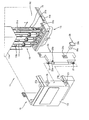
- FIG. 1 is an exploded perspective view showing a cell tab cutting apparatus and a battery pack having the same of a lithium secondary battery according to an embodiment of the present invention.
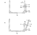
- FIG. 2 is a view for explaining the operation of the rotating member shown in FIG.
- FIG. 3 is an exploded perspective view illustrating the cutting unit illustrated in FIG. 1.
- FIG. 4 and 5 are exploded perspective views illustrating the structure of the cutting unit shown in FIG.
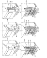
- FIG. 6A through 6F are views sequentially showing a state in which cell tabs are cut by the cell tab cutting apparatus illustrated in FIG. 1.
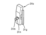
- FIG. 7 and 8 are views showing a cutter of another method that can be applied to the cutting unit.
- FIG. 1 is an exploded perspective view illustrating a cell tab cutting device and a battery pack 11 having the same of a lithium secondary battery according to an embodiment of the present invention.
- each cell module 13 is electrically connected to the outside through a terminal 13a while accommodating a plurality of unit battery cells (not shown).
- the portion where the terminals 13a of the cell module 13 are collected is covered by the cover 15d as the input / output unit 19.
- the cell module 15 accommodates a plurality of pouch-type unit battery cells and is connected to the outside through the terminal 13a.
- the battery pack 11 is a package of a plurality of cell modules 15 in the casing (15).
- the terminals 13a of the cell modules 15 are concentrated to form the input / output unit 19.
- the casing 15 may include an upper case member 15a positioned above the cell module 13, a lower case member 15b disposed below the cell module 13, and the upper and lower case members 15. Located between the 15a, 15b and the side plate (15c) in contact with the cell module 13, and the cover (15d).
- the cover 15d is part of the casing 15, and is wrapped and protected to open and close the input / output unit 19 in a state fixed to the upper and lower case members 15a and 15b.
- the side plate 15c interviews the outer surface of the cell module located on the outside of the plurality of cell modules (13).
- the side plate 15c is a metal plate plastically deformed by external force, for example, when the unit battery cell swells and expands in the thickness direction due to a swelling phenomenon, the side plate 15c is deformed by being pushed in the arrow Z direction.
- the cell tab cutting device of the present embodiment uses a physical force when the side plate 15c is pushed in the direction of the arrow Z.
- the cell tab 33 of the unit battery cell interviewed on the inner side surface of one side plate 15c is exposed to the input / output unit 19 side.
- the cell tab 33 is a portion electrically connected to an external circuit, and is a portion to be cut by a cutter to be described later (when swelling occurs). When the cell tab 33 is cut, the external circuit and the battery pack 11 are electrically disconnected.
- the rotating member 25 and the stopper 29 is rotatably installed on the cover (15d) and the cutting portion fixed to the side of the cell tab 33 ( 31).
- the cutting unit 31 is fixed to the casing 15, and a separate bracket (not shown) may be applied to the cutting unit 31 so that the cutting unit 31 may be fixed at the position.
- Two hinge portions 23 are formed on one side of the cover 15d so that the pivot member 25 can be rotatably installed.
- the hinge portion 23 has a support hole 23a and supports the pivot shaft 25a of the pivot member 25 to be rotatable.
- the rotation member 25 is a member that covers the cutting portion 31 while being supported by the hinge portion 23 and is in close contact with a part of the outer side surface of the side plate 15c. Since the rotating member 25 is in close contact with the outer surface of the side plate 15c in this manner, when the side plate 15c swells in the arrow z direction due to swelling, it is pushed in the same direction to center the rotating shaft 25a. Rotate to work.
- a support spring 27 is further provided on the pivot shaft 25a so that the pivot member 25 can always be in close contact with the side plate 15c.
- the support spring 27 is a torsion spring biased in the direction in which both ends are lifted.
- the support spring 27 is wrapped in the rotational shaft 25a, and one end of the support spring 27 is formed in the spring support groove 23b formed in the cover 15d. The end is fixed to the spring support groove 25b provided in the rotation member 25. Due to the action of the support spring 27, the rotating member 25 is always in close contact with the side plate (15c) elastically.
- the rotating member 25 is provided with a through hole 25c into which the stopper 29 is fitted.
- the through hole 25c is a rectangular hole and has a stepped portion for supporting the head portion 29b of the stopper 29 on its inward surface.
- the stopper 29 restrains upward movement of the slider 31b of the cutting portion 31 (when the rotation member 25 is in close contact with the side plate 15c) while being fitted into the through hole 25c. Element. When the rotating member 25 is pushed away from the cutting part 31 in the direction of arrow Z, no further restraining force is provided to the slider 31b. This will be described later.
- the stopper 29 acts as a bar, and includes a head part 29b inserted into and fixed to the through hole 25c and a bar part 29a extending integrally with the head part 29b.
- the latch portion 29a is inserted into the locking groove 31c of the slider 31b to be described later, and serves to restrain the slider 31b from moving up and down. As long as this function can be performed, the shape of the stopper 29 may vary.
- the cutting portion 31 is vertically extended to the guide member 31a of the rectangular frame shape to provide a moving space (31f in FIG. 3) therein, and to the moving space 31f of the guide member 31a.
- a slider 31b installed and slidable up and down and having a cutter (31k in FIG. 5) on one side, and a spring 31e elastically supporting the slider 31b to the upper portion in the drawing are configured.
- the guide member 31a is fixed to the side of the cell tab 33 using various supporting brackets (not shown), and the slider 31b sliding along the moving space 31f moves the cell tab 33. Pass in the width direction. Detailed description of the guide member 31a will be described later.
- FIG. 2A and 2B are diagrams for explaining the operation of the rotating member 25 shown in FIG.
- the rotating member 25 is fitted to one side of the cover 15d so as to be rotatable.
- the rotating shaft 25a of the rotating member 25 is supported by the hinge portion 23 so that the rotating member 25 can rotate in the direction of arrow b and the opposite direction.
- the pivot member 25 is always elastically supported in the direction of arrow a as shown in FIG. It is elastically in contact with the side plate 15c.
- FIG. 3 is an exploded perspective view illustrating the cutting unit illustrated in FIG. 1.
- a cutting part 31 is provided on the side of the cell tab 33.
- the cutting part 31 may include a guide member 31a extending in the width direction of the cell tab 33 and having a guide groove 31d formed on an inward surface thereof, and a cell tab (inside the guide member 31a). It consists of the slider 31b which slides in the width direction of 33. As shown in FIG.
- FIG. 4 and 5 are exploded perspective views showing the structure of the cutting unit 31 shown in FIG. 3 in more detail.
- the cutting portion 31 has a guide member 31a having a rectangular frame shape extending vertically, and side side protrusions 31g of both sides are inserted into the guide groove 31d of the guide member 31a.
- a slider 31b slidable along the guide groove 31d, a cutter 31k fixed to one side of the slider 31b, and a spring 31e elastically supporting the slider 31b upwards.
- a rectangular locking groove 31c is formed on the opposite side of the cutter 31k.
- the locking groove 31c is a hole into which the latch portion 29a of the stopper 29 is fitted.
- FIG. 6A through 6F are views sequentially showing a state in which cell tabs are cut by the cell tab cutting apparatus illustrated in FIG. 1.
- FIG. 6A shows a steady state before swelling occurs.
- the rotating member 25 stands by in the state in which the side plate 15c is in close contact.
- the slider 31b of the cutting part 31 provided in the inside of the said rotation member 25 is pressed down by the stopper 29, lowering as much as possible, and a spring is compressed.
- the cutter 31m shown in FIG. 7 is a disk cutter.
- the cutter 31m is rotatably provided on one side of the slider 31b by the support bracket 31n.
- the cutter 31m rotates when the slider 31b rises and passes through the cell tab 33 in the width direction, and cuts the cutting target portion of the cell tab 33.
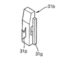
- the cutter 31p shown in FIG. 8 takes the form of a V-shaped blade. By applying the blade in the V-shape in this way, the cell tab 33 is cut in place without cutting back when cutting.
- the shape of the cutter can be changed depending on the embodiment.
- the cell tab cutting device which is configured as described above, cuts the cell tab 33 through mechanical means during swelling of the unit battery cell, and the cutting is very quick and accurate.
Landscapes
- Chemical & Material Sciences (AREA)
- Chemical Kinetics & Catalysis (AREA)
- Electrochemistry (AREA)
- General Chemical & Material Sciences (AREA)
- Engineering & Computer Science (AREA)
- Manufacturing & Machinery (AREA)
- Connection Of Batteries Or Terminals (AREA)
- Battery Mounting, Suspending (AREA)
Abstract
본 발명은 리튬이차전지의 셀 탭 커팅장치 및 이를 갖는 전지팩에 관한 것이다. 상기 커팅장치는, 케이싱내에 나란하게 패킹되는 다수의 단위전지셀을 포함하여 구성된 전지팩의 일측에 장착된 상태로, 상기 단위전지셀의 스웰링현상 발생시 동작하여 단위전지셀의 셀 탭을 절단하는 것으로서, 상기 단위전지셀의 일측부로 연장되며, 두께방향으로 부풀어오르는 단위전지셀에 밀려 위치 변경되는 변위부재와; 상기 셀 탭의 측부에 설치되고, 상기 변위부재의 위치이동시 작동하여 셀 탭을 절단하는 커팅부를 포함하는 것을 특징으로 한다. 상기와 같이 이루어지는 본 발명의 리튬이차전지의 셀 탭 커팅장치 및 이를 갖는 전지팩은, 단위전지셀이 부풀어 오르기 시작할 때, 부푸는 힘을 이용하여 셀 탭을 절단함으로써, 과충전과 과방전은 물론 외부로부터의 충격에 의한 이차전지의 폭발과 발화의 위험을 간단히 해결할 수 있으며, 특히 셀 탭의 절단을 위한 기구의 구성이 간단하고 고장의 염려가 없어 그만큼 신뢰성이 높다.
Description
[관련출원의 상호참조]
본 출원은 2012년 10월 26일 출원된 한국특허 출원번호 제10-2012-0119858호를 우선권 주장하고 있으며, 상기 특허 문헌의 내용은 참조를 위해 본 발명에 모두 포함된다
본 발명은 리튬이차전지의 셀 탭 커팅장치 및 이를 갖는 전지팩에 관한 것이다.
이차전지(二次電池)는 예컨대 스마트폰 등의 각종 휴대용 전자기기에서부터 최근 전기자동차에 이르기까지 그 적용분야가 확대되고 있으며, 계속적인 연구 개발을 통해 그 성능이 크게 개선되고 있다. 최근에 개발되는 이차전지는 종전의 재래식에 비해 작동전압이 높고 에너지 밀도가 매우 높다.
그런데, 상기 이차전지 중 리튬이온전지는, 오랜 시간동안 과충전 하게 되면, 양극 활물질과 전해액의 부반응이 일어나, 양극 활물질의 구조가 붕괴되며 전해액이 산화하고, 그에 따라 음극 활물질에서 리튬이 석출되어 폭발이나 발화할 위험성도 갖는다.
또한 일정한 온도 이상의 고온환경에 방치되면, 전극 활물질이 불안정한 상태로 활성화되고 전해액과 급격히 반응하면서 부풀어 올라 폭발하기도 한다. 상기한 리튬이온전지의 폭발 및 발화 가능성은 이차전지의 충전상태에 따라 달라진다. 과하게 충전될수록 폭발 및 발화 가능성이 높아지는 것이다.
리튬이온전지가 부풀어 올라 폭발하는 것을 스웰링(swelling) 현상이라고 하는데, 이러한 스웰링현상은 리튬이온전지의 과충전 뿐 아니라, 과방전이나 외부충격 등의 이유로 셀의 내부에서 분리막이 손상되었을 때 일어난다.
이러한 폭발과 발화의 문제를 해결하기 위하여, PTC(Positive Temperature Coefficiency resistor)라 부르는 능동소자를 양극쪽에 직렬 연결하고, 상기 PTC의 내부 저항으로 하여금 과충전시 입력전류를 차단하게 하는 이른바 보호회로가 적용되기도 하였다.
그러나 상기한 PTC는, 이차전지가 과열되면 이차전지로 흐르는 전류의 흐름을 억제하여 전지가 더 이상 충전되는 것을 방지하는 것으로서, 과충전시 이차전지의 온도가 상승할 경우에 입력전류를 차단하는 것일 뿐, 가령 이미 충전된 이차전기가 고온에 노출되었을 때에나, 과방전 되었을 때, 또는 외부의 충격을 받아 내부의 차단막이 손상되었을 때에 이차전지를 보호할 수는 없는 것이다.
이와같이 종전에는, 과충전 이외의 이유에 따른 이차전지의 과열시 이차전지를 보호하기 위한 장치가 없었다.
본 발명은 상기 문제점을 해소하고자 창출한 것으로서, 단위전지셀이 부풀어 오르기 시작할 때, 부푸는 힘을 이용하여 셀 탭을 절단함으로써, 과충전과 과방전은 물론 외부로부터의 충격에 의한 이차전지의 폭발과 발화의 위험을 간단히 해결할 수 있으며, 특히 셀 탭의 절단을 위한 기구의 구성이 간단하고 고장의 염려가 없어 그만큼 신뢰성이 높은 리튬이차전지의 셀 탭 커팅장치 및 이를 갖는 전지팩을 제공함에 목적이 있다.
상기 목적을 달성하기 위한 본 발명의 리튬이차전지의 셀 탭 커팅장치는, 케이싱내에 나란하게 패킹되는 다수의 단위전지셀을 포함하여 구성된 전지팩의 일측에 장착된 상태로, 상기 단위전지셀의 스웰링현상 발생시 동작하여 단위전지셀의 셀 탭을 절단하는 것으로서, 상기 단위전지셀의 일측부로 연장되며, 두께방향으로 부풀어오르는 단위전지셀에 밀려 위치 변경되는 변위부재와; 상기 셀 탭의 측부에 설치되고, 상기 변위부재의 위치이동시 작동하여 셀 탭을 절단하는 커팅부를 포함하는 것을 특징으로 한다.
또한, 상기 변위부재는; 회동축을 통해 전지팩의 케이싱에 회동 가능하도록 설치되며, 상기 단위전지셀의 일측부로 연장되어 단위전지셀이 부풀어 오를 때 상기 회동축을 중심으로 회동하는 회동부재인 것을 특징으로 한다.
또한, 상기 커팅부는; 상기 셀 탭의 측부에 고정되며 셀 탭의 폭방향으로 연장된 가이드홈을 갖는 가이드부재와, 상기 가이드부재에 지지된 상태로 가이드홈을 따라 슬라이딩 이동 가능한 슬라이더와, 상기 슬라이더에 고정되며 슬라이더의 슬라이딩 이동시 상기 셀 탭을 폭방향으로 지나며 셀 탭을 절단하는 커터와, 상기 슬라이더를 슬라이딩 이동시키는 슬라이더구동수단을 포함하는 것을 특징으로 한다.
아울러, 상기 슬라이더구동수단은; 압축된 상태로 대기하다가 상기 회동부재의 회동시 팽창하여 슬라이더를 이동시키는 압축코일 스프링이고, 상기 회동부재에는; 상기 슬라이더의 주행 경로상에 위치한 상태로, 상기 슬라이더의 이동을 억제하며, 스웰링현상에 의해 회동부재가 회동할 때 상기 주행경로에서 빠져나와, 슬라이더가 스프링의 팽창력을 받아 슬라이딩 이동하게 하는 스토퍼가 구비된 것을 특징으로 한다.
또한, 상기 슬라이더의 커터 반대측 부위에는 걸림홈이 형성되어 있고, 상기 스토퍼는, 상기 걸림홈에 끼워진 상태로 슬라이더의 이동을 차단하는 것을 특징으로 한다.
또한, 상기 케이싱에는, 상기 전지팩의 전력 입출력 단자가 모여있는 입출력부를 개방 가능하게 커버링하는 커버가 포함되고, 상기 회동부재는, 상기 커버의 일측에 회동 가능하도록 설치된 것을 특징으로 한다.
또한, 상기 회동부재의 회동축에는, 회동부재를 단위전지셀측으로 탄성 지지하는 지지스프링이 더 구비된 것을 특징으로 한다.
아울러, 상기 커터는, 상기 슬라이더의 일측면에 수직으로 고정되며 슬라이더의 이동방향으로 경사진 형태를 취하는 것을 특징으로 한다.
또한, 상기 커터는; 상기 슬라이더의 일측면에 고정되며 지지력을 제공하는 지지브라켓에 회전 가능하게 지지되며 디스크의 형태를 취하는 것을 특징으로 한다.
또한, 상기 목적을 달성하기 위한 본 발명의 전지팩은, 상호 나란하게 패킹되는 다수의 단위전지셀을 포함하며, 그 일측에 전력 단자가 위치하는 하나 이상의 셀모듈과; 상기 셀모듈을 수용하며, 상기 전력 단자를 개방 가능하게 커버링하는 커버를 포함하는 케이싱과; 상기 커버의 일측에 회동 가능하게 설치되며 상기 단위전지셀의 일측부로 연장되어 스웰링현상 발생시 두께방향으로 부풀어오르는 단위전지셀에 밀려 회동하는 변위부재와; 상기 단위전지셀에 구비되는 셀 탭의 측부에 배치된 것으로서, 상기 변위부재의 회동에 종동하여 셀 탭을 절단하는 커팅부를 구비하는 것을 특징으로 한다.
또한, 상기 변위부재는; 회동축을 통해 커버에 회동 가능하도록 설치되고, 상기 단위전지셀의 일측부로 연장된 회동부재인 것을 특징으로 한다.
또한, 상기 커팅부는; 상기 셀 탭의 측부에 고정되며 셀 탭의 폭방향으로 연장된 가이드홈을 갖는 가이드부재와, 상기 가이드부재에 지지된 상태로 가이드홈을 따라 슬라이딩 이동 가능한 슬라이더와, 상기 슬라이더에 고정되며 슬라이더의 슬라이딩 이동시 상기 셀 탭을 폭방향으로 지나며 셀 탭을 절단하는 커터와, 상기 슬라이더를 슬라이딩 이동시키는 슬라이더구동수단을 포함하는 것을 특징으로 한다.
아울러, 상기 슬라이더구동수단은; 압축된 상태로 대기하다가 상기 회동부재의 회동시 팽창하여 슬라이더를 이동시키는 압축코일 스프링이고, 상기 회동부재에는; 상기 슬라이더의 이동 경로상에 위치한 상태로, 상기 슬라이더의 이동을 억제하며, 스웰링현상에 의해 회동부재가 회동할 때 상기 이동 경로에서 빠져나와, 슬라이더가 스프링의 팽창력을 받아 슬라이딩 이동하게 하는 스토퍼가 구비된 것을 특징으로 한다.
또한, 상기 슬라이더의 커터 반대측 부위에는 걸림홈이 형성되어 있고, 상기 스토퍼는, 상기 걸리홈에 끼워져 슬라이더의 이동을 차단하는 것을 특징으로 한다.
또한, 상기 회동부재의 회동축에는, 회동부재를 단위전지셀측으로 탄성 지지하는 지지스프링이 구비된 것을 특징으로 한다.
또한, 상기 커터는, 상기 슬라이더의 일측면에 수직으로 고정되며 슬라이더의 이동방향으로 경사진 형태를 취하는 것을 특징으로 한다.
아울러, 상기 커터는; 상기 슬라이더의 일측면에 고정되며 지지력을 제공하는 지지브라켓에 회전 가능하게 지지되며 디스크의 형태를 취하는 것을 특징으로 한다.
상기와 같이 이루어지는 본 발명의 리튬이차전지의 셀 탭 커팅장치 및 이를 갖는 전지팩은, 단위전지셀이 부풀어 오르기 시작할 때, 부푸는 힘을 이용하여 셀 탭을 절단함으로써, 과충전과 과방전은 물론 외부로부터의 충격에 의한 이차전지의 폭발과 발화의 위험을 간단히 해결할 수 있으며, 특히 셀 탭의 절단을 위한 기구의 구성이 간단하고 고장의 염려가 없어 그만큼 신뢰성이 높다.
도 1은 본 발명의 일 실시예에 따른 리튬이차전지의 셀 탭 커팅장치 및 이를 갖는 전지팩을 도시한 분해 사시도이다.
도 2는 상기 도 1에 도시한 회동부재의 동작방식을 설명하기 위하여 도시한 도면이다.
도 3은 상기 도 1에 도시한 커팅부를 분해하여 도시한 사시도이다.
도 4 및 도 5는 상기 도 3에 도시한 커팅부의 구조를 설명하기 위하여 도시한 분해 사시도이다.
도 6a 내지 도 6f는 상기 도 1에 도시한 셀 탭 커팅장치를 통해 셀 탭을 커팅하는 모습을 순차적으로 나타내 보인 도면이다.
도 7 및 도 8은 상기 커팅부에 적용할 수 있는 다른 방식의 커터를 나타내 보인 도면이다.
이하, 본 발명에 따른 하나의 실시예를 첨부된 도면을 참조하여 보다 상세히 설명하기로 한다.
도 1은 본 발명의 일 실시예에 따른 리튬이차전지의 셀 탭 커팅장치 및 이를 갖는 전지팩(11)을 도시한 분해 사시도이다.
도면을 참조하면, 다수의 셀모듈(13)이 케이싱(15)내에 나란하게 패키징 되어 있음을 알 수 있다. 상기 각 셀모듈(13)은 다수의 단위전지셀(미도시)을 수용한 상태로 단자(13a)를 통해 외부와 전기적으로 접속된다. 상기 셀모듈(13)의 단자(13a)들이 모여있는 부분은 입출력부(19)로서 커버(15d)에 의해 덮어진다.
상기 셀모듈(15)은 다수의 파우치형 단위전지셀을 포개어 수용한 것으로서 단자(13a)를 통해 외부에 접속가능한 것이다. 또한 전지팩(11)은 다수의 셀모듈(15)을 케이싱(15)에 패키징한 것이다. 상기 각 셀모듈(15)의 단자(13a)는 집중 배치되어 입출력부(19)를 이룬다.
상기 케이싱(15)은, 도면상 셀모듈(13)의 상부에 위치하는 상부케이스부재(15a)와, 셀모듈(13)의 하부에 배치되는 하부케이스부재(15b)와, 상기 상하부케이스부재(15a,15b)의 사이에 위치하며 셀모듈(13)에 접하는 사이드플레이트(15c)와, 상기 커버(15d)를 포함한다.
상기 커버(15d)는 케이싱(15)의 일부로서, 상하부케이스부재(15a,15b)에 고정된 상태로 상기 입출력부(19)를 개방 가능하게 감싸며 보호한다. 또한 상기 사이드플레이트(15c)는 다수의 셀모듈(13) 중 외측에 자리한 셀모듈의 바깥쪽면에 면접한다. 특히 상기 사이드플레이트(15c)는 외력에 의해 소성변형되는 금속판으로서 가령 단위전지셀이 스웰링현상에 의해 두께 방향으로 부풀어 오르며 팽창할 때, 화살표 Z 방향으로 밀려 변형된다.
후술하겠지만, 본 실시예의 셀 탭 커팅장치는, 상기 사이드플레이트(15c)가 화살표 Z방향으로 밀려 이동할 때의 물리적인 힘을 이용하는 것이다.
아울러, 도 3에 나타나 있는 바와같이, 일측 사이드플레이트(15c)의 내측면에 면접하고 있는 단위전지셀의 셀 탭(33)이, 입출력부(19) 측으로 노출되어 있다. 상기 셀 탭(33)은 외부 회로와 전기적으로 접속되는 부분으로서, (스웰링현상이 발생할 때) 후술할 커터를 통해 절단될 부위이다. 상기 셀 탭(33)이 절단되면 외부의 회로와 전지팩(11)이 전기적으로 차단됨은 물론이다.
한편, 본 실시예에 따른 셀 탭 커팅장치는, 상기 커버(15d)에 회전 가능하게 설치되는 회동부재(25) 및 스토퍼(29)와, 상기 셀 탭(33)의 측부에 고정되는 커팅부(31)를 포함한다. 상기 커팅부(31)는 케이싱(15)에 고정되며, 커팅부(31)가 상기 위치에 고정될 수 있도록 별도의 브라켓(미도시)을 얼마든지 적용할 수 있다.
상기 회동부재(25)를 회동 가능하게 설치할 수 있도록, 상기 커버(15d)의 일측면에는 두 개의 힌지부(23)가 아래 위로 형성되어 있다. 상기 힌지부(23)는 지지구멍(23a)을 가지며 회동부재(25)의 회동축(25a)을 축회전 가능하도록 지지한다.
상기 회동부재(25)는, 힌지부(23)에 지지된 상태로 커팅부(31)를 커버하며 사이드플레이트(15c)의 일부 외측면에 면접 밀착하는 부재이다. 이와같이 회동부재(25)가 사이드플레이트(15c)의 외측면에 밀착하고 있으므로, 스웰링현상에 의해 사이드플레이트(15c)가 화살표 z방향으로 부풀어 오를 때, 같은 방향으로 밀려 회동축(25a)을 중심으로 회동 운동한다.
상기 회동부재(25)가 사이드플레이트(15c)에 항상 밀착할 수 있도록, 상기 회동축(25a)에는 지지스프링(27)이 더 설치된다. 상기 지지스프링(27)은, 양단부가 오므라지는 방향으로 바이어스된 토션스프링으로서, 상기 회동축(25a)을 감싼 상태로, 일단부는 커버(15d)에 형성되어 있는 스프링지지홈(23b)에, 타단부는 회동부재(25)에 마련되어 있는 스프링지지홈(25b)에 고정된다. 상기 지지스프링(27)의 작용으로 인해, 회동부재(25)는 항상 사이드플레이트(15c)에 탄력적으로 밀착한다.
또한 상기 회동부재(25)에는 스토퍼(29)가 끼워져 결합하는 관통구멍(25c)이 마련되어 있다. 상기 관통구멍(25c)은 직사각 형태의 구멍으로서 그 내향면에 스토퍼(29)의 헤드부(29b)를 지지하는 단턱을 갖는다.
상기 스토퍼(29)는, 관통구멍(25c)에 끼움 결합한 상태로, (회동부재(25)가 사이드플레이트(15c)에 밀착시) 커팅부(31)의 슬라이더(31b)의 상향 이동을 억제하는 요소이다. 상기 회동부재(25)가 화살표 Z방향으로 밀려 커팅부(31)로부터 멀어지면 슬라이더(31b)에 더 이상의 억제력을 제공하지 못한다. 이에 대해서는 후술하기로 한다.
상기 스토퍼(29)는, 마치 빗장의 역할을 하는 것으로서, 상기 관통구멍(25c)에 삽입 고정되는 헤드부(29b)와, 상기 헤드부(29b)에 일체를 이루며 수평으로 연장된 빗장부(29a)로 이루어진다. 상기 빗장부(29a)는 후술할 슬라이더(31b)의 걸림홈(31c)에 삽입되어, 슬라이더(31b)가 위아래로 움직이지 못하게 구속하는 역할을 한다. 이러한 기능을 할 수 있는 한, 스토퍼(29)의 형상은 얼마든지 달라질 수 있다.
한편, 상기 커팅부(31)는, 수직으로 연장되며 내부에 이동공간(도 3의 31f)을 제공하는 사각틀 형태의 가이드부재(31a)와, 상기 가이드부재(31a)의 이동공간(31f)에 설치되며 상하로 슬라이딩 가능하고 일측에 커터(도 5의 31k)를 갖는 슬라이더(31b)와, 상기 슬라이더(31b)를 도면상 상부로 탄성 지지하는 스프링(31e)을 포함하여 구성된다.
상기 가이드부재(31a)는 각종 지지용 브라켓(미도시)을 이용해 상기 셀 탭(33)의 측부에 고정되어, 이동공간(31f)을 따라 슬라이딩 이동하는 슬라이더(31b)가 셀 탭(33)을 폭방향으로 통과한다. 상기 가이드부재(31a)에 대한 자세한 설명은 후술된다.
도 2a 및 도 2b는 상기 도 1에 도시한 회동부재(25)의 동작방식을 설명하기 위하여 도시한 도면이다.
도시한 바와같이, 상기 커버(15d)의 일측에 회동부재(25)가 회동 가능하게 끼워져 있다. 상기 회동부재(25)의 회동축(25a)이 힌지부(23)에 지지되어 회동부재(25)가 화살표 b방향 및 그 반대방향으로 회동 가능한 것이다.
특히, 상기 회동축(25a)에는 지지스프링(도 1의 27)이 구비되어 있으므로, 회동부재(25)는 도 2a에 도시한 바와같이 항상 화살표 a 방향으로 탄성 지지된다. 사이드플레이트(15c)에 탄력적으로 접하는 것이다.
상기 회동부재(25)는 단위전지셀의 스웰링이 발생하지 않을 때에는, 화살표 a방향으로 최대한 이동한 상태를 유지하며, 이 때 스토퍼(29)의 빗장부(29a)는 슬라이더(31b)의 걸림홈(31c)에 삽입되어 있다. (이 상태를 이하의 설명에서 닫힌상태라 칭한다.)
상기 닫힌상태에서, 비정상적인 이유에 의해 단위전지셀의 스웰링 현상이 발생하여, 사이드플레이트(15c)가 화살표 z방향으로 부풀어 오르면, 상기 회동부재(25)가 사이드플레이트(15c)에 의해 밀리며 화살표 b방향으로 회동한다(이하, 열린상태라 칭함). 이 때 상기 빗장부(29a)가 슬라이더(31b)로부터 분리되고, 슬라이더(31b)는 스프링(31e)에 의해 상부로 튀어오르며 셀 탭(33)을 폭방향으로 커팅한다.
도 3은 상기 도 1에 도시한 커팅부를 분해하여 도시한 사시도이다.
도시한 바와같이, 상기 셀 탭(33)의 측부에 커팅부(31)가 구비된다. 상기 커팅부(31)는, 셀 탭(33)의 폭방향으로 연장되며 내향면에 가이드홈(31d)이 형성되어 있는 가이드부재(31a)와, 상기 가이드부재(31a)의 내측에서 셀 탭(33)의 폭방향으로 슬라이딩 이동하는 슬라이더(31b)로 구성된다.
따라서 상기한 바와같이 상기 슬라이더(31b)에 고정되어 있는 커터(31k)가 커팅대상부위(A)를 절단할 수 있는 것이다.
도 4 및 도 5는 상기 도 3에 도시한 커팅부(31)의 구조를 보다 자세히 도시한 분해 사시도이다.
도시한 바와같이, 상기 커팅부(31)는 수직으로 연장된 직사각 프레임형태의 가이드부재(31a)와, 상기 가이드부재(31a)의 가이드홈(31d) 내에 양측의 사이드돌기(31g)가 삽입되어 가이드홈(31d)을 따라 슬라이딩 가능한 슬라이더(31b)와, 상기 슬라이더(31b)의 일측면에 고정된 커터(31k)와, 상기 슬라이더(31b)를 상부로 탄력 지지하는 스프링(31e)으로 이루어진다.
또한 상기 슬라이더(31b)에 있어서, 커터(31k)의 반대편에는 사각의 걸림홈(31c)이 형성되어 있다. 상기 걸림홈(31c)은 스토퍼(29)의 빗장부(29a)가 끼워지는 구멍이다.
상기 스토퍼(29)는 회동부재(25)에 고정된 상태로 수평방향으로만 움직이므로, 상기 슬라이더(31b)를 최대한 하강시킨 상태에서, 빗장부(29a)를 걸림홈(31c)에 삽입하면, 스프링(31e)이 압축된 상태로 대기한다.
이 상태에서, 단위전지셀이 부풀어 사이드플레이트(15c)가 화살표 z방향으로 밀리면, 빗장부(29a)가 회동부재(25)와 함께 수평 이동하며 걸림홈(31c)으로부터 빠져나간다. 상기 슬라이더(31b)는, 빗장부(29a)가 걸림홈(31c)에서 빠져나가는 순간 스프링(31e)의 작용에 의해 상부로 튀어올라 상기 셀 탭(33)의 커팅대상부위(A)를 커팅한다.
도 6a 내지 도 6f는 상기 도 1에 도시한 셀 탭 커팅장치를 통해 셀 탭을 커팅하는 모습을 순차적으로 나타내 보인 도면이다.
도 6a는 스웰링현상이 발생하기 전의 정상상태이다. 도시한 바와같이, 회동부재(25)가 사이드플레이트(15c) 최대한 밀착한 상태로 대기하고 있다. 이 때 상기 회동부재(25)의 내측에 구비되어 있는 커팅부(31)의 슬라이더(31b)는 최대한 하부로 내려진 채 스토퍼(29)에 의해 눌린 상태이고, 스프링은 압축되어 있다.
상기 닫힌 상태에서, 단위전지셀의 스웰링현상이 발생하여 사이드플레이트(15c)가 화살표 z 방향으로 부풀면, 도 6b에 나타낸 것처럼, 상기 회동부재(25)는 사이드플레이트(15c)에 밀려 화살표 b방향으로 회동한다. 이 때 상기 스토퍼(29)의 빗장부(29a)가 걸림홈(31c)으로부터 빠져나가기 시작한다.(도 6c)
마침내, 빗장부(29a)가 걸림홈(31c)에서 완전히 빠지면 그 순간, 슬라이더(31b)는 스프링(31e)의 탄성력에 의해 상부로 튀어오르며 상기 가이드홈(31d)을 따라 상승하며 상기 셀 탭(33)의 커팅대상부위(A)를 절단한다.(도 6e 및 도 6f) 이에 따라, 전지팩과 외부의 회로가 전기적으로 단절되는 것이다.
도 7 및 도 8은 상기 슬라이더(31b)에 적용할 수 있는 다른 방식의 커터를 나타내 보인 도면이다.
도 7에 도시한 커터(31m)는 디스크형 커터이다. 상기 커터(31m)는 지지브라켓(31n)에 의해 슬라이더(31b)의 일측면에 회전 가능하게 구비된다. 상기 커터(31m)는 슬라이더(31b)가 상승하며 셀 탭(33)을 폭방향으로 지날 때 회전하며 셀 탭(33)의 커팅대상부위를 절단한다.
도 8에 도시한 커터(31p)는 칼날이 V 자의 형태를 취한다. 이와같이 칼날을 V 자 형태로 적용함으로써, 커팅시 상기 셀 탭(33)이 뒤로 물러나지 않고 그 자리에서 그대로 절단된다.
상기한 커터의 형태는 실시예에 따라 얼마든지 변경할 수 있음은 물론이다.
결국, 상기한 바와같이 이루어지는 본 실시예에 따른 셀 탭 커팅장치는, 단위전지셀의 스웰링시 기구적 수단을 통해 셀 탭(33)을 절단하는 것으로서, 절단이 매우 신속하고 정확한 것이다.
이상, 본 발명을 구체적인 실시예를 통하여 상세하게 설명하였으나, 본 발명은 상기 실시예에 한정하지 않고, 본 발명의 기술적 사상의 범위내에서 통상의 지식을 가진 자에 의하여 여러 가지 변형이 가능하다.
[부호의 설명]
11:전지팩
13:셀모듈
13a:단자
15:케이싱
15a:상부케이스부재
15b:하부케이스부재
15c:사이드플레이트
15d:커버
19:입출력부
23:힌지부
23a:지지구멍
23b:스프링지지홈
25:회동부재
25a:회동축
25b:스프링지지홈
25c:관통구멍
27:지지스프링
29:스토퍼
29a:빗장부
29b:헤드부
31:커팅부
31a:가이드부재
31b:슬라이더
31c:걸림홈
31d:가이드홈
31e:스프링
31f:이동공간
31g:사이드돌기
31k:커터
31m:커터
Claims (17)
- 케이싱내에 나란하게 패킹되는 다수의 단위전지셀을 포함하여 구성된 전지팩의 일측에 장착된 상태로, 상기 단위전지셀의 스웰링현상 발생시 동작하여 단위전지셀의 셀 탭을 절단하는 것으로서,상기 단위전지셀의 일측부로 연장되며, 두께방향으로 부풀어오르는 단위전지셀에 밀려 위치 변경되는 변위부재와;상기 셀 탭의 측부에 설치되고, 상기 변위부재의 위치이동시 작동하여 셀 탭을 절단하는 커팅부를 포함하는 것을 특징으로 하는 리튬이차전지의 셀 탭 커팅장치.
- 제 1항에 있어서,상기 변위부재는;회동축을 통해 전지팩의 케이싱에 회동 가능하도록 설치되며, 상기 단위전지셀의 일측부로 연장되어 단위전지셀이 부풀어 오를 때 상기 회동축을 중심으로 회동하는 회동부재인 것을 특징으로 하는 리튬이차전지의 셀 탭 커팅장치.
- 제 2항에 있어서,상기 커팅부는;상기 셀 탭의 측부에 고정되며 셀 탭의 폭방향으로 연장된 가이드홈을 갖는 가이드부재와,상기 가이드부재에 지지된 상태로 가이드홈을 따라 슬라이딩 이동 가능한 슬라이더와,상기 슬라이더에 고정되며 슬라이더의 슬라이딩 이동시 상기 셀 탭을 폭방향으로 지나며 셀 탭을 절단하는 커터와,상기 슬라이더를 슬라이딩 이동시키는 슬라이더구동수단을 포함하는 것을 특징으로 하는 리튬이차전지의 셀 탭 커팅장치.
- 제 3항에 있어서,상기 슬라이더구동수단은;압축된 상태로 대기하다가 상기 회동부재의 회동시 팽창하여 슬라이더를 이동시키는 압축코일 스프링이고,상기 회동부재에는;상기 슬라이더의 주행 경로상에 위치한 상태로, 상기 슬라이더의 이동을 억제하며, 스웰링현상에 의해 회동부재가 회동할 때 상기 주행경로에서 빠져나와, 슬라이더가 스프링의 팽창력을 받아 슬라이딩 이동하게 하는 스토퍼가 구비된 것을 특징으로 하는 리튬이차전지의 셀 탭 커팅장치.
- 제 4항에 있어서,상기 슬라이더의 커터 반대측 부위에는 걸림홈이 형성되어 있고,상기 스토퍼는, 상기 걸림홈에 끼워진 상태로 슬라이더의 이동을 차단하는 것을 특징으로 하는 리튬이차전지의 셀 탭 커팅장치.
- 제 2항에 있어서,상기 케이싱에는, 상기 전지팩의 전력 입출력 단자가 모여있는 입출력부를 개방 가능하게 커버링하는 커버가 포함되고,상기 회동부재는, 상기 커버의 일측에 회동 가능하도록 설치된 것을 특징으로 하는 리튬이차전지의 셀 탭 커팅장치.
- 제 6항에 있어서,상기 회동부재의 회동축에는, 회동부재를 단위전지셀측으로 탄성 지지하는 지지스프링이 더 구비된 것을 특징으로 하는 리튬이차전지의 셀 탭 커팅장치.
- 제 3항에 있어서,상기 커터는,상기 슬라이더의 일측면에 수직으로 고정되며 슬라이더의 이동방향으로 경사진 형태를 취하는 것을 특징으로 하는 리튬이차전지의 셀 탭 커팅장치.
- 제 3항에 있어서,상기 커터는;상기 슬라이더의 일측면에 고정되며 지지력을 제공하는 지지브라켓에 회전 가능하게 지지되며 디스크의 형태를 취하는 것을 특징으로 하는 리튬이차전지의 셀 탭 커팅장치.
- 상호 나란하게 패킹되는 다수의 단위전지셀을 포함하며, 그 일측에 전력 단자가 위치하는 하나 이상의 셀모듈과;상기 셀모듈을 수용하며, 상기 전력 단자를 개방 가능하게 커버링하는 커버를 포함하는 케이싱과;상기 커버의 일측에 회동 가능하게 설치되며 상기 단위전지셀의 일측부로 연장되어 스웰링현상 발생시 두께방향으로 부풀어오르는 단위전지셀에 밀려 회동하는 변위부재와;상기 단위전지셀에 구비되는 셀 탭의 측부에 배치된 것으로서, 상기 변위부재의 회동에 종동하여 셀 탭을 절단하는 커팅부를 구비하는 것을 특징으로 하는 전지팩.
- 제 10항에 있어서,상기 변위부재는;회동축을 통해 커버에 회동 가능하도록 설치되고, 상기 단위전지셀의 일측부로 연장된 회동부재인 것을 특징으로 하는 전지팩.
- 제 11항에 있어서,상기 커팅부는;상기 셀 탭의 측부에 고정되며 셀 탭의 폭방향으로 연장된 가이드홈을 갖는 가이드부재와,상기 가이드부재에 지지된 상태로 가이드홈을 따라 슬라이딩 이동 가능한 슬라이더와,상기 슬라이더에 고정되며 슬라이더의 슬라이딩 이동시 상기 셀 탭을 폭방향으로 지나며 셀 탭을 절단하는 커터와,상기 슬라이더를 슬라이딩 이동시키는 슬라이더구동수단을 포함하는 것을 특징으로 하는 전지팩.
- 제 12항에 있어서,상기 슬라이더구동수단은;압축된 상태로 대기하다가 상기 회동부재의 회동시 팽창하여 슬라이더를 이동시키는 압축코일 스프링이고,상기 회동부재에는;상기 슬라이더의 이동 경로상에 위치한 상태로, 상기 슬라이더의 이동을 억제하며, 스웰링현상에 의해 회동부재가 회동할 때 상기 이동 경로에서 빠져나와, 슬라이더가 스프링의 팽창력을 받아 슬라이딩 이동하게 하는 스토퍼가 구비된 것을 특징으로 하는 전지팩.
- 제 13항에 있어서,상기 슬라이더의 커터 반대측 부위에는 걸림홈이 형성되어 있고,상기 스토퍼는, 상기 걸리홈에 끼워져 슬라이더의 이동을 차단하는 것을 특징으로 하는 전지팩.
- 제 11항에 있어서,상기 회동부재의 회동축에는, 회동부재를 단위전지셀측으로 탄성 지지하는 지지스프링이 구비된 것을 특징으로 하는 전지팩.
- 제 12항에 있어서,상기 커터는,상기 슬라이더의 일측면에 수직으로 고정되며 슬라이더의 이동방향으로 경사진 형태를 취하는 것을 특징으로 하는 전지팩.
- 제 12항에 있어서,상기 커터는;상기 슬라이더의 일측면에 고정되며 지지력을 제공하는 지지브라켓에 회전 가능하게 지지되며 디스크의 형태를 취하는 것을 특징으로 하는 전지팩.
Applications Claiming Priority (2)
| Application Number | Priority Date | Filing Date | Title |
|---|---|---|---|
| KR1020120119858A KR101965398B1 (ko) | 2012-10-26 | 2012-10-26 | 리튬이차전지의 셀 탭 커팅장치 및 이를 갖는 전지팩 |
| KR10-2012-0119858 | 2012-10-26 |
Publications (1)
| Publication Number | Publication Date |
|---|---|
| WO2014065637A1 true WO2014065637A1 (ko) | 2014-05-01 |
Family
ID=50544934
Family Applications (1)
| Application Number | Title | Priority Date | Filing Date |
|---|---|---|---|
| PCT/KR2013/009607 Ceased WO2014065637A1 (ko) | 2012-10-26 | 2013-10-25 | 리튬이차전지의 셀 탭 커팅장치 및 이를 갖는 전지팩 |
Country Status (2)
| Country | Link |
|---|---|
| KR (1) | KR101965398B1 (ko) |
| WO (1) | WO2014065637A1 (ko) |
Cited By (3)
| Publication number | Priority date | Publication date | Assignee | Title |
|---|---|---|---|---|
| DE102015214094A1 (de) * | 2015-07-24 | 2017-01-26 | Bayerische Motoren Werke Aktiengesellschaft | Mechanische Notabschaltvorrichtung für eine stromführende Leitung in einem Kraftfahrzeug und Kraftfahrzeug mit einer solchen Notabschaltvorrichtung |
| CN107196008A (zh) * | 2017-06-01 | 2017-09-22 | 金山电化工业(惠州)有限公司 | 一种电池组拆卸机构 |
| EP3512008A4 (en) * | 2017-07-06 | 2019-10-02 | LG Chem, Ltd. | BATTERY MODULE AND BATTERY PACK AND VEHICLE THEREFOR |
Families Citing this family (3)
| Publication number | Priority date | Publication date | Assignee | Title |
|---|---|---|---|---|
| KR102364159B1 (ko) * | 2017-08-01 | 2022-02-18 | 주식회사 엘지에너지솔루션 | 전극 탭 절단 장치를 포함하는 파우치형 이차전지 |
| KR102203250B1 (ko) * | 2017-11-29 | 2021-01-13 | 주식회사 엘지화학 | 엔드 프레임을 구비한 배터리 모듈 |
| KR102494847B1 (ko) | 2021-04-02 | 2023-02-06 | 주식회사 원익피앤이 | 이차전지 셀의 테라스 커팅장치 및 커팅방법 |
Citations (5)
| Publication number | Priority date | Publication date | Assignee | Title |
|---|---|---|---|---|
| JPH10208726A (ja) * | 1997-01-28 | 1998-08-07 | Japan Storage Battery Co Ltd | 電流遮断装置及びこの電流遮断装置を内蔵する電池 |
| KR20020080428A (ko) * | 2000-02-18 | 2002-10-23 | 마츠시타 덴끼 산교 가부시키가이샤 | 각형 전지의 안전기구 및 그 제조방법 |
| US20090017365A1 (en) * | 2005-05-23 | 2009-01-15 | Matsushita Electric Industrial Co., Ltd. | Safety mechanism for liminate battery |
| KR20090113521A (ko) * | 2008-04-28 | 2009-11-02 | 에스케이에너지 주식회사 | 전기자동차용 2차 전지의 안전 스위치 및 이를 이용한전기자동차용 2차 전지의 충방전 시스템 |
| JP2011210390A (ja) * | 2010-03-29 | 2011-10-20 | Honda Motor Co Ltd | 電池及び電池モジュール |
Family Cites Families (1)
| Publication number | Priority date | Publication date | Assignee | Title |
|---|---|---|---|---|
| KR101608694B1 (ko) * | 2009-07-20 | 2016-04-05 | 에스케이이노베이션 주식회사 | 2차 전지용 과충전 방지 장치 |
-
2012
- 2012-10-26 KR KR1020120119858A patent/KR101965398B1/ko active Active
-
2013
- 2013-10-25 WO PCT/KR2013/009607 patent/WO2014065637A1/ko not_active Ceased
Patent Citations (5)
| Publication number | Priority date | Publication date | Assignee | Title |
|---|---|---|---|---|
| JPH10208726A (ja) * | 1997-01-28 | 1998-08-07 | Japan Storage Battery Co Ltd | 電流遮断装置及びこの電流遮断装置を内蔵する電池 |
| KR20020080428A (ko) * | 2000-02-18 | 2002-10-23 | 마츠시타 덴끼 산교 가부시키가이샤 | 각형 전지의 안전기구 및 그 제조방법 |
| US20090017365A1 (en) * | 2005-05-23 | 2009-01-15 | Matsushita Electric Industrial Co., Ltd. | Safety mechanism for liminate battery |
| KR20090113521A (ko) * | 2008-04-28 | 2009-11-02 | 에스케이에너지 주식회사 | 전기자동차용 2차 전지의 안전 스위치 및 이를 이용한전기자동차용 2차 전지의 충방전 시스템 |
| JP2011210390A (ja) * | 2010-03-29 | 2011-10-20 | Honda Motor Co Ltd | 電池及び電池モジュール |
Cited By (3)
| Publication number | Priority date | Publication date | Assignee | Title |
|---|---|---|---|---|
| DE102015214094A1 (de) * | 2015-07-24 | 2017-01-26 | Bayerische Motoren Werke Aktiengesellschaft | Mechanische Notabschaltvorrichtung für eine stromführende Leitung in einem Kraftfahrzeug und Kraftfahrzeug mit einer solchen Notabschaltvorrichtung |
| CN107196008A (zh) * | 2017-06-01 | 2017-09-22 | 金山电化工业(惠州)有限公司 | 一种电池组拆卸机构 |
| EP3512008A4 (en) * | 2017-07-06 | 2019-10-02 | LG Chem, Ltd. | BATTERY MODULE AND BATTERY PACK AND VEHICLE THEREFOR |
Also Published As
| Publication number | Publication date |
|---|---|
| KR101965398B1 (ko) | 2019-04-03 |
| KR20140053656A (ko) | 2014-05-08 |
Similar Documents
| Publication | Publication Date | Title |
|---|---|---|
| WO2014065637A1 (ko) | 리튬이차전지의 셀 탭 커팅장치 및 이를 갖는 전지팩 | |
| WO2022031056A1 (ko) | 배터리 모듈, 그것을 포함하는 배터리 팩, 및 자동차 | |
| WO2021002626A1 (ko) | 배터리 모듈, 이를 포함하는 배터리 랙 및 전력 저장 장치 | |
| EP2339672B1 (en) | Battery module and battery pack using same | |
| WO2019009625A1 (ko) | 배터리 모듈과 이를 포함하는 배터리 팩 및 자동차 | |
| WO2022080908A1 (ko) | 전지 모듈 및 이를 포함하는 전지 팩 | |
| WO2021145706A1 (ko) | 방염 시트를 구비한 배터리 모듈, 이를 포함하는 배터리 랙, 및 전력 저장 시스템 | |
| WO2021075780A1 (ko) | 배터리 팩 및 전자 디바이스 및 자동차 | |
| WO2015167046A1 (ko) | 이차 전지용 회로 기판 및 이를 포함하는 배터리 팩 | |
| WO2009157676A9 (ko) | 안전성이 향상된 중대형 전지팩 | |
| WO2017039139A1 (ko) | 배터리 팩 | |
| WO2009134046A9 (ko) | 전기자동차용 2차 전지의 안전 스위치 및 이를 이용한 전기자동차용 2차 전지의 충방전 시스템 | |
| WO2010055994A1 (ko) | 센스 저항 파괴를 감지하여 배터리 팩을 보호하는 장치 및 방법 | |
| WO2023096261A1 (ko) | 안전성이 향상된 배터리 팩 | |
| WO2022196983A1 (ko) | 전지 모듈 및 이를 포함하는 전지팩 | |
| WO2022158833A1 (ko) | 화재 방지 성능이 향상된 배터리 팩 | |
| US20150137767A1 (en) | Protection apparatus for rechargeable battery | |
| WO2022060003A1 (ko) | 배터리 모듈, 배터리 팩, 및 이를 포함하는 자동차 | |
| WO2022092662A1 (ko) | 캡 조립체 및 이를 포함하는 이차 전지 | |
| WO2023058927A1 (ko) | 안전성이 향상된 배터리 팩 | |
| WO2016122129A1 (ko) | 전지팩 | |
| WO2023214670A1 (ko) | 배터리 모듈의 선택적 분리가 가능한 배터리 팩 | |
| WO2022139163A1 (ko) | 이차전지 및 이의 제조 방법 | |
| WO2014073880A1 (ko) | 이차전지 | |
| WO2024005581A1 (ko) | 배터리 모듈, 배터리 팩 및 이를 포함하는 자동차 |
Legal Events
| Date | Code | Title | Description |
|---|---|---|---|
| 121 | Ep: the epo has been informed by wipo that ep was designated in this application |
Ref document number: 13848242 Country of ref document: EP Kind code of ref document: A1 |
|
| NENP | Non-entry into the national phase |
Ref country code: DE |
|
| 122 | Ep: pct application non-entry in european phase |
Ref document number: 13848242 Country of ref document: EP Kind code of ref document: A1 |