WO2014065326A1 - スピーカシステム及び映像表示装置 - Google Patents
スピーカシステム及び映像表示装置 Download PDFInfo
- Publication number
- WO2014065326A1 WO2014065326A1 PCT/JP2013/078709 JP2013078709W WO2014065326A1 WO 2014065326 A1 WO2014065326 A1 WO 2014065326A1 JP 2013078709 W JP2013078709 W JP 2013078709W WO 2014065326 A1 WO2014065326 A1 WO 2014065326A1
- Authority
- WO
- WIPO (PCT)
- Prior art keywords
- speaker
- sound
- speaker system
- band
- emits
- Prior art date
- Legal status (The legal status is an assumption and is not a legal conclusion. Google has not performed a legal analysis and makes no representation as to the accuracy of the status listed.)
- Ceased
Links
Images




Classifications
-
- H—ELECTRICITY
- H04—ELECTRIC COMMUNICATION TECHNIQUE
- H04N—PICTORIAL COMMUNICATION, e.g. TELEVISION
- H04N5/00—Details of television systems
- H04N5/64—Constructional details of receivers, e.g. cabinets or dust covers
- H04N5/642—Disposition of sound reproducers
-
- H—ELECTRICITY
- H04—ELECTRIC COMMUNICATION TECHNIQUE
- H04R—LOUDSPEAKERS, MICROPHONES, GRAMOPHONE PICK-UPS OR LIKE ACOUSTIC ELECTROMECHANICAL TRANSDUCERS; ELECTRIC HEARING AIDS; PUBLIC ADDRESS SYSTEMS
- H04R1/00—Details of transducers, loudspeakers or microphones
- H04R1/02—Casings; Cabinets ; Supports therefor; Mountings therein
- H04R1/028—Casings; Cabinets ; Supports therefor; Mountings therein associated with devices performing functions other than acoustics, e.g. electric candles
-
- H—ELECTRICITY
- H04—ELECTRIC COMMUNICATION TECHNIQUE
- H04R—LOUDSPEAKERS, MICROPHONES, GRAMOPHONE PICK-UPS OR LIKE ACOUSTIC ELECTROMECHANICAL TRANSDUCERS; ELECTRIC HEARING AIDS; PUBLIC ADDRESS SYSTEMS
- H04R1/00—Details of transducers, loudspeakers or microphones
- H04R1/20—Arrangements for obtaining desired frequency or directional characteristics
- H04R1/22—Arrangements for obtaining desired frequency or directional characteristics for obtaining desired frequency characteristic only
- H04R1/28—Transducer mountings or enclosures modified by provision of mechanical or acoustic impedances, e.g. resonator, damping means
- H04R1/2803—Transducer mountings or enclosures modified by provision of mechanical or acoustic impedances, e.g. resonator, damping means for loudspeaker transducers
-
- H—ELECTRICITY
- H04—ELECTRIC COMMUNICATION TECHNIQUE
- H04R—LOUDSPEAKERS, MICROPHONES, GRAMOPHONE PICK-UPS OR LIKE ACOUSTIC ELECTROMECHANICAL TRANSDUCERS; ELECTRIC HEARING AIDS; PUBLIC ADDRESS SYSTEMS
- H04R1/00—Details of transducers, loudspeakers or microphones
- H04R1/02—Casings; Cabinets ; Supports therefor; Mountings therein
- H04R1/023—Screens for loudspeakers
-
- H—ELECTRICITY
- H04—ELECTRIC COMMUNICATION TECHNIQUE
- H04R—LOUDSPEAKERS, MICROPHONES, GRAMOPHONE PICK-UPS OR LIKE ACOUSTIC ELECTROMECHANICAL TRANSDUCERS; ELECTRIC HEARING AIDS; PUBLIC ADDRESS SYSTEMS
- H04R1/00—Details of transducers, loudspeakers or microphones
- H04R1/20—Arrangements for obtaining desired frequency or directional characteristics
- H04R1/22—Arrangements for obtaining desired frequency or directional characteristics for obtaining desired frequency characteristic only
- H04R1/26—Spatial arrangements of separate transducers responsive to two or more frequency ranges
-
- H—ELECTRICITY
- H04—ELECTRIC COMMUNICATION TECHNIQUE
- H04R—LOUDSPEAKERS, MICROPHONES, GRAMOPHONE PICK-UPS OR LIKE ACOUSTIC ELECTROMECHANICAL TRANSDUCERS; ELECTRIC HEARING AIDS; PUBLIC ADDRESS SYSTEMS
- H04R2499/00—Aspects covered by H04R or H04S not otherwise provided for in their subgroups
- H04R2499/10—General applications
- H04R2499/15—Transducers incorporated in visual displaying devices, e.g. televisions, computer displays, laptops
Definitions
- the present invention relates to a speaker system and a video display device, and more particularly to a speaker system having two speakers each emitting sound in different bands in one amplifier channel and a video display device including the speaker system.
- video display devices such as television receivers with a built-in speaker are now mainly thin and narrow framed from the viewpoint of improving the design.
- Narrowing the frame means that the width of the frame around the display screen by a liquid crystal panel or the like is narrowed to reduce the so-called frame around the display screen as much as possible.
- design restrictions are also imposed when speakers are installed, and the selection range of speakers is very narrow.
- Patent Document 1 discloses a speaker for controlling directivity without changing the external dimensions of the speaker. .
- This speaker outputs sound by the diaphragm, and is output from the second part of the diaphragm by the acoustic adjustment member provided between the first part of the diaphragm and the listening position by the user. The interference of the sound output from the first part with respect to the sound transmitted to the position is adjusted.
- a mid-range speaker that emits relatively low-frequency sound and a relatively high frequency
- a tweeter that emits the sound on the band side
- the sound band emitted from the mid-range speaker often overlaps the sound band emitted from the tweeter. is there.
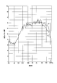
- FIG. 8 is a diagram illustrating an example of the sound pressure characteristics of the mid-range speaker and the tweeter.
- M is an example of the sound pressure characteristic of the mid-range speaker
- T is an example of the sound pressure characteristic of the tweeter.
- FIG. 9 is a diagram showing an example of the state of sound interference that changes depending on the listening point.
- the sound pressure level of the sound emitted from both the midrange speaker and the tweeter is heard at different listening points, the sound pressure level is shown. It shows an example in which changes. If there is a wavelength range A that overlaps with the same sound pressure level in the band of sound emitted from the midrange speaker and tweeter, the listening point (the position of the microphone that collects the sound) is shifted in that wavelength range. When this occurs, the sound pressure characteristics change due to interference, which appears as deterioration in sound quality.
- a network circuit using a coil or a capacitor in a configuration using a mid-range speaker and a tweeter is used to solve the problem of sound quality degradation caused by interference between sounds emitted from two speakers.
- the band of sound emitted from the mid-range speaker and the band of sound emitted from the tweeter are separated, and interference of sound from these two speakers is prevented.
- Patent Document 1 is intended to improve the directivity of a speaker by providing an acoustic adjustment member for one speaker.
- the two speakers that emit sounds in different bands as described above are provided. This is not applicable in order to prevent deterioration in sound quality in a speaker system having one amplifier channel.
- the present invention has been made in view of the above circumstances, and in a speaker system having two speakers each emitting sound in different bands in one amplifier channel, it is emitted from the speakers without the need to configure a network circuit.
- a speaker system capable of obtaining high-quality sound characteristics without depending on the listening point by providing a configuration that effectively limits the band of the sound, and a video display device including the speaker system are provided. The purpose is to do.
- the first technical means of the present invention is a speaker system having at least two speakers that emit sounds of different bands per amplifier channel, along the speaker axis of each speaker.
- a shielding object is provided in front of the speaker that emits a relatively low-band sound.
- the shield is located in front of a central portion of the speaker that emits a high-frequency sound in a concentrated manner. It is characterized by being arranged.
- the shield forms an opening having a total area of a predetermined size or more in front of a region where a relatively low-band speaker emits sound.
- the opening is provided closer to the speaker side that emits the sound on the higher band side than the center of the sound emitting part of the speaker that emits the sound on the lower band side. Is.
- the predetermined object is placed on the shielding object on the side opposite to the side where the opening is provided with respect to the center of the speaker that emits the low-band sound.
- An opening having an area smaller than the size of is provided.
- the fifth technical means is a video display device provided with the speaker system of any one of the first to fourth technical means.
- the present invention in a speaker system having two amplifiers each emitting sound in different bands in one amplifier channel, it is possible to effectively limit the band of sound emitted from the speakers without the need to configure a network circuit.
- a speaker system capable of obtaining high-quality sound characteristics without depending on a listening point, and a video display device including the speaker system.
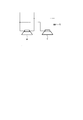
- FIG. 1 is a schematic diagram showing a configuration of an embodiment of a speaker system according to the present invention.
- FIG. 1A is a schematic front view of a mid-range speaker in which a shielding object is disposed, and FIG. FIG.
- 1 is a mid-range speaker
- 2 is a shield
- 21a to 21d are openings in front of the speaker formed by the shield 2.
- the speaker system of the present embodiment has two speakers that emit sounds of different bands in one amplifier channel, and the mid-range speaker 1 that emits relatively low-band sound as two speakers.
- a tweeter (not shown in FIG. 1) that emits a relatively high-band sound.
- the shield 2 includes a plurality of openings 21a to 21d, and includes an area where the front of the sound emission area (diaphragm area) of the mid-range speaker 1 is shielded by the shield 2, and an area where the sound is released by the openings 21a to 21d. It is formed.
- the openings 21a to 21d are provided to emit sound from the midrange speaker 1 to the listener side, and the total opening area of the openings 21a to 21d is a total area of a predetermined size or more. Further, the shape and number of the openings 21a to 21d are not limited, and for example, a plurality of small-area round holes may be gathered to form openings having a predetermined total area or more.
- the shield 2 By providing the shield 2, it is possible to block the high frequency band sound from the mid range speaker and prevent the high frequency band sound from being emitted forward. Since the high frequency band has a small diffraction angle and a large attenuation by the shield 2, the sound in the high frequency band emitted from the midrange speaker 1 can be effectively attenuated.
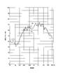
- FIG. 2 is a diagram showing an example of the sound pressure characteristic depending on the presence or absence of a shield.
- P1 is an example of the sound pressure characteristic when the shield 2 is not provided in front of the mid-range speaker 1
- P2 is An example of sound pressure characteristics when the shield 2 is provided in front of the mid-range speaker 1 is shown.
- the sound pressure level in the high frequency band can be attenuated.
- the sound pressure level on the high frequency band side of the mid-range speaker is attenuated. Therefore, it is possible to suppress voice deterioration due to interference.
- said shielding object 2 is arrange
- a speaker generally emits a sound having a relatively high frequency in a central portion. Therefore, in order to efficiently attenuate the sound in the high frequency band, when the front of the sound emission area of the mid-range speaker 1 is shielded by the shielding object 2, the front of the center portion of the mid-range speaker 1 is shielded. . Thereby, it is possible to efficiently attenuate only the sound in the high frequency band without affecting the sound in the other band emitted from the mid-range speaker 1.
- the range of the central portion can be a predetermined range including the center of the midrange speaker 1.
- the central region at this time may not have a symmetrical shape, but may have a shape having a region deviated in any direction from the center of the speaker.
- FIG. 3 is a schematic diagram showing the configuration of still another embodiment of the speaker system according to the present invention.
- the shielding object 2 is provided in both of the regions on both sides of the center of the speaker in the region in front of the region in which the midrange speaker 1 that emits relatively low-band sound emits sound. It arrange
- FIG. 3A is a schematic front view of a mid-range speaker in which the shielding object is arranged
- FIG. 3B is a schematic top view thereof.
- openings 21c and 21d formed by the shield 2 are provided on one side of the center c of the mid-range speaker 1.
- the center c is, for example, a point-symmetrical center of the diaphragm region of the midrange speaker 1.
- FIG. 3C shows an unfavorable example of the arrangement of the openings formed by the shield 2.
- two openings 21 a and 21 d are provided on both sides of the center c of the midrange speaker 1.
- the left and right distances between the openings 21a and 21d become long, and a difference in distance to the listening point occurs, which increases the possibility of interference.
- FIGS. 3A and 3B by providing an opening on one side with respect to the center c, interference due to sound emitted from the opening can be suppressed.
- FIG. 4 is a schematic diagram showing the configuration of still another embodiment of the speaker system according to the present invention.
- FIG. 4 shows a tweeter 3 included in the speaker system in addition to the configuration of the mid-range speaker 1 and the shield 2 shown in FIG.
- the mid-range speaker 1 and the tweeter 3 are provided per amplifier channel for outputting an audio signal. Accordingly, in the case of a speaker system that outputs a two-channel audio signal, two midrange speakers 1 and one tweeter 3 are provided, one for each amplifier channel.
- the shielding object 2 is provided in front of the mid-range speaker 1, and the shielding object 2 has a total area in front of the region where the mid-range speaker 1 emits sound. Openings 21c and 21d having a predetermined size or larger are formed. The openings 21c and 21d are not provided in both regions on both sides of the center c of the mid-range speaker 1. In the present embodiment, the openings 21c and 21d are provided closer to the tweeter 3 side than the center c of the sound emitting portion of the mid-range speaker 1.
- the shielding object 2 is disposed so as to shield the front of the center portion of the midrange speaker 1, and the openings 21 c and 21 d formed by the shielding object 2 are moved to one side of the center c of the midrange speaker 1.
- the openings 21c and 21d provided on one side with respect to the center c of the midrange speaker 1 are closer to the tweeter 3 side than the center c of the sound emitting portion of the midrange speaker 1.
- a shorter distance difference means a shorter distance between the speakers.
- the output sound pressure level of the mid-range speaker 1 is sufficiently attenuated in a frequency band where canceling interference can occur, attenuation due to interference with the tweeter 3 can be greatly reduced.
- the opening of the shield 2 that emits sound from the mid-range speaker 1 is provided close to the tweeter 3 side, and the distance between the opening and the tweeter 3 is shortened, so that the sound emitted from each speaker is reduced. Sound quality degradation due to interference can be suppressed.
- FIG. 5 is a schematic diagram showing the configuration of still another embodiment of the speaker system according to the present invention.
- openings 21c and 21d having a total area of a predetermined size or more are formed in the front shield 2 of the midrange speaker 1 as shown in FIGS.
- the shield on the side opposite to the side where the openings 21c and 21d are provided with respect to the center c of the midrange speaker 1
- an opening 22 having an area smaller than a predetermined size is provided.
- the opening 22 is provided on the side opposite to the openings 21c and 21d having a total area of a predetermined size or more with respect to the center c of the midrange speaker 1, and is provided between the shield 2 and the midrange speaker 1. It can be provided in the vicinity of the space. As shown in FIG. 5, the opening 22 is provided near the outside of the front area of the midrange speaker 1, but may be provided in the front area of the midrange speaker 1. By providing this opening 22, it is possible to reduce the stiffness (hardness of the air) of the space formed by the shield 2, thereby reducing the sound pressure drop over the entire frequency band caused by the space stiffness. Can be prevented.
- FIG. 6 is a diagram showing an example of a sound pressure characteristic depending on the presence or absence of an opening for improving the stiffness of the space.
- P3 indicates a sound when the opening 2 smaller than a predetermined size is not provided in the shield 2.
- An example of the pressure characteristic, P4 shows an example of the sound pressure characteristic when the shield 2 is provided in front of the mid-range speaker 1.
- FIG. 7 is a diagram showing an example of an external configuration of a television receiver, which is one of video display devices including the speaker system according to the present invention.
- the television receiver 10 is provided with a front frame 12 around the front surface of the display unit 11 using a liquid crystal panel or the like.
- the front frame 12 constitutes a frame of the display unit 11, and in recent years, the so-called narrow frame is narrowed.
- each optical element and electric / electronic element of the television receiver 10 including the display unit 11, a speaker system including the midrange speaker 1 and the tweeter 3, and the like are accommodated in the housing 13.
- the television receiver 10 has means for selecting a broadcast signal received by an antenna, demodulating, decoding, and generating a reproduction video signal and a reproduction audio signal. A predetermined image is appropriately added to the reproduction video signal. It has a function of processing and displaying on the display unit 11 and outputting a sound signal for reproduction from the speaker system.
- the speaker system included in the television receiver 10 can adopt the configuration of each of the above-described embodiments, and is configured as a speaker system having two speakers that emit different band sounds per amplifier channel. These two speakers can include a mid-range speaker that emits a relatively low-band side sound and a tweeter that emits a relatively high-band side sound. In addition to these, a woofer that handles a lower frequency region can be provided.
- the shielding object 2 which shields the front of the midrange speaker 1 mentioned above can be provided as a part of housing
- the speaker system has at least two speakers that emit sounds of different bands per amplifier channel, and is relatively low when the sound emission direction along the speaker axis of each speaker is the front. You may have a shield in front of the speaker which discharge
- the above-described shielding object is disposed in front of the central portion of the speaker that intensively emits high-frequency sound, among the speakers that emit relatively low-band sounds. It may be. Thereby, it is possible to efficiently attenuate only the sound in the high frequency band without affecting the sound in the other band emitted from the mid-range speaker 1.
- the shielding member has a predetermined size or more in both regions on both sides of the center of the speaker among regions in front of the region in which the speaker emitting sound on the low band side emits sound. It may be arranged so as not to provide an opening of the total area. As a result, the openings are aggregated and provided on both sides of the center of the mid-range speaker 1 so that the sounds emitted through the openings do not interfere with each other, and high-quality sound is emitted. Can do.
- the above-mentioned shielding object forms an opening in front of a region where the relatively low-band speaker emits sound, and the opening of the speaker emits low-band sound. It may be provided closer to the speaker side that emits the sound on the relatively higher band side than the center of the emitting portion. As a result, the distance between the opening from which the sound from the midrange speaker 1 is emitted and the tweeter 3 is shortened, and even if the sound in the same frequency band is emitted with the same sound pressure, the distance to the listening point is reached. A difference in distance is unlikely to occur, and attenuation of sound due to interference can be suppressed.
- an opening having an area smaller than the predetermined size is provided in a shield on the side opposite to the side where the opening is provided with respect to the center of the sound of the speaker that emits sound on the low band side. It may be a thing. Thereby, the stiffness (hardness of the air) of the space formed by the shielding object 2 can be reduced, and thereby the sound pressure drop over the entire frequency band caused by the stiffness of the space can be prevented. Become.
- the speaker system may include a housing that accommodates each speaker, and the shielding object may be provided as a part of the housing.
- the shielding object may be provided as a part of the housing.
Landscapes
- Engineering & Computer Science (AREA)
- Signal Processing (AREA)
- Physics & Mathematics (AREA)
- Acoustics & Sound (AREA)
- Multimedia (AREA)
- Health & Medical Sciences (AREA)
- Otolaryngology (AREA)
- Circuit For Audible Band Transducer (AREA)
- Details Of Audible-Bandwidth Transducers (AREA)
Abstract
ネットワーク回路を構成する必要なく、スピーカから放出された音の帯域を効果的に制限する構成を備えることで、リスニングポイントに依存することなく高音質の音響特性が得られるようにする。それぞれ異なる帯域の音を放出する2個のスピーカを1チャンネルごとに有するスピーカシステムにおいて、各スピーカのスピーカ軸に沿った音の放出方向(F)を前方とするとき、相対的に低帯域側の音を放出するミッドレンジスピーカ(1)の前方に、遮蔽物(2)を有する。
Description
本発明は、スピーカシステム及び映像表示装置に関し、より詳細には、それぞれ異なる帯域の音を放出する2個のスピーカをアンプ1チャンネルに有するスピーカシステムと、当該スピーカシステムを備えた映像表示装置に関する。
例えばスピーカを内蔵したテレビ受像機等の映像表示装置は、昨今ではそのデザイン性を高めるとの観点から、薄型で狭額縁化されたものが主流となっている。狭額縁化とは、液晶パネル等による表示画面の周囲のフレームの幅を狭くして、表示画面の周囲の所謂額縁をできるだけ少なくすることをいう。このような薄型、狭額縁化に伴い、スピーカを設置する場合にも設計的な制約が生じ、スピーカの選択の幅は非常に狭いものとなっている。しかしながら、このような設計的制約があるなかで、音質劣化を改善し、高品位の音響特性が得られるスピーカシステムが求められる。
スピーカシステムを大型化することなく音質を改善するための技術として、例えば、特許文献1には、スピーカの外形寸法を変えずに、指向性をコントロールすることを目的とするスピーカが開示されている。このスピーカは、振動板によって音響を出力するもので、振動板の第一の部位とユーザによる聴取位置との間に設けられた音響調整部材によって、振動板の第二の部位から出力されて聴取位置へ伝達する音響に対する、第一の部位から出力された音響の干渉を調整するようにしている。
例えばテレビ受像機等に搭載するスピーカシステムでは、再生可能周波数帯域を拡大して品位の高い音響特性を得るために、相対的に低域側の音を放出するミッドレンジスピーカと、相対的に高域側の音を放出するツイータとを用いることがある。
しかしながら、上記のようなテレビ受像機の薄型、狭額縁化の要求による設計的な制約により、ミッドレンジスピーカから放出する音の帯域と、ツイータから放出する音の帯域とが重なってしまうことがしばしばある。
しかしながら、上記のようなテレビ受像機の薄型、狭額縁化の要求による設計的な制約により、ミッドレンジスピーカから放出する音の帯域と、ツイータから放出する音の帯域とが重なってしまうことがしばしばある。
図8は、ミッドレンジスピーカとツイータとの音圧特性の一例を図で、図中、Mはミッドレンジスピーカの音圧特性、Tはツイータの音圧特性の一例である。
図8に示すように、ミッドレンジスピーカとツイータとを使用するスピーカシステムにおいて、それぞれのスピーカが受け持つ帯域、つまり各スピーカから放出される音の帯域が同程度の音圧レベルで重なる現象が生じる。図8の例では、例えばAに示す帯域で、同程度の音圧レベルの波長域が重なる。
これにより、両スピーカから放出される音が干渉し、音質が劣化する。このとき、リスニングポイントによって両スピーカからの音の位相差が変化するため、リスニングポイントに依存して音質が変化する。
図8に示すように、ミッドレンジスピーカとツイータとを使用するスピーカシステムにおいて、それぞれのスピーカが受け持つ帯域、つまり各スピーカから放出される音の帯域が同程度の音圧レベルで重なる現象が生じる。図8の例では、例えばAに示す帯域で、同程度の音圧レベルの波長域が重なる。
これにより、両スピーカから放出される音が干渉し、音質が劣化する。このとき、リスニングポイントによって両スピーカからの音の位相差が変化するため、リスニングポイントに依存して音質が変化する。
図9は、リスニングポイントによって変化する音の干渉の様子の一例を示す図で、ミッドレンジスピーカとツイータとの両方から放出された音の音圧レベルを異なるリスニングポイントで聞いたときに音圧レベルが変化する例を示すものである。
ミッドッレンジスピーカとツイータとから放出される音の帯域に同程度の音圧レベルで重なる波長域Aがある場合、その波長領域では、リスニングポイント(音を集音するマイクの位置)をずらしていったときに、干渉により音圧特性が変化し、これが音質の劣化となって現れる。
ミッドッレンジスピーカとツイータとから放出される音の帯域に同程度の音圧レベルで重なる波長域Aがある場合、その波長領域では、リスニングポイント(音を集音するマイクの位置)をずらしていったときに、干渉により音圧特性が変化し、これが音質の劣化となって現れる。
リスニングポイントをずらしていくことにより、ミッドレンジスピーカとツイータとのそれぞれからリスニングポイントまでの距離が変化する。このきに、両スピーカから同じ波長の音が放出されていると、リスニングポイントの移動に応じてその波長の音の位相差が変化し、干渉の状態が変化する。従ってリスニングポイントに依存して音圧レベルが変化し、その結果音質の劣化が生じる。
このような2つのスピーカから放出された音が干渉することによる音質劣化の問題に対して、例えば、ハイファイオーディオシステムにおいては、ミッドレンジスピーカとツイータを使用する構成でコイルやコンデンサを用いてネットワーク回路を構築し、ミッドレンジスピーカにおける不要な高域の音を遮断するとともに、ツイータにおける不要な低域の音を遮断する。そしてこれにより、ミッドレンジスピーカから放出する音の帯域と、ツイータから放出する音の帯域とを分離し、これら二つのスピーカからの音の干渉を防ぐことが行われている。
しかしながら、上記のようなネットワーク回路を構成したとしても、ネットワーク回路の次数が低ければ、目的とする帯域の音の遮断が不十分となる。ましてや、上記のような設計的制約を有するテレビ受像機等にこれらのスピーカを搭載する場合、例えばスペースの制約やコスト上の制約からネットワーク回路にコイルを配置することが困難になる。
例えば、図10のネットワーク回路図に示すように、ミッドレンジスピーカMとツイータTとを有する構成において、簡易的にツイータT側にコンデンサCを設置し、ツイータTの低域をカットして干渉をできるだけ防ぐ程度のことが行われる。しかしながら、この場合でも干渉帯域の音の遮断は十分ではなく、音質劣化を解消することはできない。また、テレビ受像機等の映像表示装置では部品コストに対する要求も厳しく、目的とする帯域遮断性能を十分に有するネットワーク回路を組むことができないことがほとんどである。
例えば、図10のネットワーク回路図に示すように、ミッドレンジスピーカMとツイータTとを有する構成において、簡易的にツイータT側にコンデンサCを設置し、ツイータTの低域をカットして干渉をできるだけ防ぐ程度のことが行われる。しかしながら、この場合でも干渉帯域の音の遮断は十分ではなく、音質劣化を解消することはできない。また、テレビ受像機等の映像表示装置では部品コストに対する要求も厳しく、目的とする帯域遮断性能を十分に有するネットワーク回路を組むことができないことがほとんどである。
また、電気回路の周波数伝達特性やソフトウェア上での信号処理を通じて周波数特性を変化させるイコライザを使用して、周波数特性を調整することも考えられるが、ミッドレンジスピーカとツイータとから放出させる音声信号は同一ソースの音声信号であるため、その音声信号にこのようなイコライザを適用してもうまく周波数帯域を制御することができない。また、同一ソースの音声信号を二つに分けてからそれぞれの音声信号に対して上記のようなイコライザによる処理を行うことも考えられるが、スペースの制約やコスト上の制約、構造の複雑化・煩雑化等が生じるため現実的ではない。
これらの結果、ミッドレンジスピーカとツイータとの干渉による音質劣化を許容することになってしまっている。
これらの結果、ミッドレンジスピーカとツイータとの干渉による音質劣化を許容することになってしまっている。
特許文献1の技術は、1つのスピーカに対して音響調整部材を設けることでスピーカの指向性を改善しようとするものであり、上記のようなそれぞれ異なる帯域の音を放出する2個のスピーカをアンプ1チャンネルに有するスピーカシステムにおいて、その音質劣化を防ぐために適用できるものではない。
本発明は、上述のごとき実情に鑑みてなされたもので、それぞれ異なる帯域の音を放出する2個のスピーカをアンプ1チャンネルに有するスピーカシステムにおいて、ネットワーク回路を構成する必要なく、スピーカから放出された音の帯域を効果的に制限する構成を備えることで、リスニングポイントに依存することなく高音質の音響特性が得られるようにしたスピーカシステムと、そのスピーカシステムを備えた映像表示装置とを提供することを目的とする。
上記課題を解決するために、本発明の第1の技術手段は、それぞれ異なる帯域の音を放出する少なくとも2個のスピーカをアンプ1チャンネルあたりに有するスピーカシステムにおいて、各スピーカのスピーカ軸に沿った音の放出方向を前方とするとき、相対的に低帯域側の音を放出するスピーカの前方に、遮蔽物を有することを特徴としたものである。
第2の技術手段は、第1の技術手段において、前記遮蔽物が、相対的に低帯域側の音を放出するスピーカの中でも、特に高い周波数の音を集中的に放出するスピーカ中央部の前方に配置されていることを特徴としたものである。
第3の技術手段は、第1の技術手段において、前記遮蔽物が、相対的に低帯域側のスピーカが音を放出する領域の前方に、所定の大きさ以上の総面積の開口を形成し、該開口は、前記低帯域側の音を放出するスピーカの音の放出部の中心よりも、相対的に高帯域側の音を放出するスピーカ側に寄せて設けられていることを特徴としたものである。
第4の技術手段は、第3の技術手段において、前記低帯域側の音を放出するスピーカの中心に対して、前記開口が寄せて設けられた側と反対側の前記遮蔽物に、前記所定の大きさより小さい面積の開口を設けることを特徴としたものである。
第5の技術手段は、第1~4のいずれか1の技術手段のスピーカシステムを備えた映像表示装置である。
本発明によれば、それぞれ異なる帯域の音を放出する2個のスピーカをアンプ1チャンネルに有するスピーカシステムにおいて、ネットワーク回路を構成する必要なく、スピーカから放出された音の帯域を効果的に制限する構成を備えることで、リスニングポイントに依存することなく高音質の音響特性が得られるようにしたスピーカシステムと、そのスピーカシステムを備えた映像表示装置を提供することができる。
以下に本発明に係るスピーカシステムの実施形態を添付された図面を参照しながら具体的に説明する。なお、実施形態を説明するための全図において、同様の機能を有する部分には同じ符号を付け、その繰り返しの説明は省略する。
図1は、本発明によるスピーカシステムの一実施形態の構成を示す概略図で、図1(A)は、遮蔽物を配置したミッドレンジスピーカの正面概略図、図1(B)は、その上面概略図である。図1において、1はミッドレンジスピーカ、2は遮蔽物、21a~21dは遮蔽物2によって形成されるスピーカ前方の開口である。
本実施形態のスピーカシステムは、それぞれ異なる帯域の音を放出する2個のスピーカをアンプ1チャンネルに有するもので、2個のスピーカとして、相対的に低帯域側の音を放出するミッドレンジスピーカ1と、相対的に高帯域側の音を放出するツイータ(図1では図示せず)とが用いられる。
図1は、本発明によるスピーカシステムの一実施形態の構成を示す概略図で、図1(A)は、遮蔽物を配置したミッドレンジスピーカの正面概略図、図1(B)は、その上面概略図である。図1において、1はミッドレンジスピーカ、2は遮蔽物、21a~21dは遮蔽物2によって形成されるスピーカ前方の開口である。
本実施形態のスピーカシステムは、それぞれ異なる帯域の音を放出する2個のスピーカをアンプ1チャンネルに有するもので、2個のスピーカとして、相対的に低帯域側の音を放出するミッドレンジスピーカ1と、相対的に高帯域側の音を放出するツイータ(図1では図示せず)とが用いられる。
そして本実施形態の構成は、各スピーカのスピーカ軸に沿った音の放出方向Fを前方とするとき、ミッドレンジスピーカ1の前方に、遮蔽物2を備える。遮蔽物2は、複数の開口21a~21dを備え、ミッドレンジスピーカ1の音の放出領域(振動板領域)の前方を遮蔽物2によって遮蔽する領域と、開口21a~21dによって解放する領域とが形成される。開口21a~21dは、ミッドレンジスピーカ1からの音を聴取者側に放出するために設けられるもので、開口21a~21dの総開口面積は、所定の大きさ以上の総面積とされる。また、開口21a~21dの形状や数は限定されるものではなく、例えば、小面積の丸孔を複数集合させて所定の総面積以上の開口を形成したものであってもよい。
遮蔽物2を備えることにより、ミッドレンジスピーカから放出された音のうち高周波帯域の音を遮断して、高周波帯域の音が前方に放出されないようにすることができる。高周波帯域は回折角が小さく、遮蔽物2による減衰が大きいため、ミッドレンジスピーカ1から放出される高周波帯域の音を効果的に減衰させることができる。
図2は、遮蔽物の有無による音圧特性の一例を示す図で、図中、P1は、ミッドレンジスピーカ1の前方に遮蔽物2を設けていないときの音圧特性の例、P2は、ミッドレンジスピーカ1の前方に遮蔽物2を設けたときの音圧特性の例を示す。図示するように、ミッドレンジスピーカ1の前方に遮蔽物2を設けることにより、高周波帯域の音圧レベルを減衰させることができる。これにより、ミッドレンジスピーカ1とツイータとを備えたスピーカシステムにおいて、ミッドレンジスピーカの高周波帯域側の音圧レベルが減衰しているため、同程度の音圧レベルで波長域が重複する音が削減され、干渉による音声劣化を抑えることができるようになる。
また、本実施形態では、上記の遮蔽物2は、相対的に高い周波数の音が集中的に放出されるスピーカ中央部の前方を遮蔽するように配置されていることが好ましい。スピーカは、一般にその中央部にて相対的に高い周波数の音が集中的に放出されている。
従って、高周波帯域の音を効率的に減衰させるために、ミッドレンジスピーカ1の音の放出領域前方を遮蔽物2で遮蔽するとき、そのミッドレンジスピーカ1の中央部前方を遮蔽するように構成する。これにより、ミッドレンジスピーカ1から放出される他の帯域の音に影響を与えることなく、高周波帯域の音のみを効率的に減衰させることができる。中央部の範囲としては、ミッドレンジスピーカ1の中心を含む所定範囲の領域とすることができる。またこのときの中央部の領域は、対称形状でなく、スピーカ中心からいずれかの方向に偏った領域をもつ形状としてもよい。
そして上記構成により、高周波帯域の音を効果的に減衰させたミッドレンジスピーカ1からの音と、ツイータから放出された音との干渉を防ぎ、良好な音質により音を放出させることができる。
従って、高周波帯域の音を効率的に減衰させるために、ミッドレンジスピーカ1の音の放出領域前方を遮蔽物2で遮蔽するとき、そのミッドレンジスピーカ1の中央部前方を遮蔽するように構成する。これにより、ミッドレンジスピーカ1から放出される他の帯域の音に影響を与えることなく、高周波帯域の音のみを効率的に減衰させることができる。中央部の範囲としては、ミッドレンジスピーカ1の中心を含む所定範囲の領域とすることができる。またこのときの中央部の領域は、対称形状でなく、スピーカ中心からいずれかの方向に偏った領域をもつ形状としてもよい。
そして上記構成により、高周波帯域の音を効果的に減衰させたミッドレンジスピーカ1からの音と、ツイータから放出された音との干渉を防ぎ、良好な音質により音を放出させることができる。
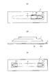
図3は、本発明によるスピーカシステムの更に他の実施形態の構成を示す概略図である。本実施形態において、遮蔽物2は、相対的に低帯域側の音を放出するミッドレンジスピーカ1が音を放出する領域の前方の領域のうち、スピーカの中心の両側の領域の両方に、所定の大きさ以上の開口を設けないように配置される。図3(A)は、このときの遮蔽物を配置したミッドレンジスピーカの正面概略図、図3(B)は、その上面概略図である。
この例では、ミッドレンジスピーカ1の中心cの片側に、遮蔽物2によって形成される開口21c,21dが設けられている。中心cは、例えば、ミッドレンジスピーカ1の振動板領域の点対称中心である。この構成により、ミッドレンジスピーカ1の中心cの両側に開口が分散することなく、開口が集約されて設けられるため、各開口21c,21dを通して放出される音同士が干渉することなく、高音質の音を放出させることができる。また、このときに、ミッドレンジスピーカ1の中心cを含むスピーカ中央部の前方を遮蔽物2が遮蔽するように構成されているので、高周波帯域の音のみを効率的に減衰させる効果が得られる。
図3(C)は、遮蔽物2により形成される開口の配置の好ましくない例を示している。この図に示すように、二つの開口21a,21dが、ミッドレンジスピーカ1の中心cの両側に分散して設けられている。この場合、開口21a,21d間の左右の距離が長くなり、リスニングポイントまでの距離の差が生じて干渉が起きる可能性が高くなる。これに対して、上記図3(A)、(B)のように、中心cに対して片側に開口を設けることで、開口から放出された音による干渉を抑えることができる。
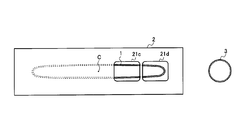
図4は、本発明によるスピーカシステムの更に他の実施形態の構成を示す概略図である。図4では、図3のミッドレンジスピーカ1と遮蔽物2との構成に加えて、スピーカシステムが有するツイータ3が示されている。本発明に係る実施形態では、ミッドレンジスピーカ1とツイータ3とは、音声信号を出力するためのアンプ1チャンネルあたりに設けられている。従って、2チャンネルの音声信号を出力するスピーカシステムであれば、ミッドレンジスピーカ1とツイータ3とはアンプ1チャンネルごとに1つずつで、計2つずつ設けられている。
そして本実施形態では、図3の構成と同様に、ミッドレンジスピーカ1の前方に遮蔽物2が設けられ、その遮蔽物2は、ミッドレンジスピーカ1が音を放出する領域の前方に総面積が所定の大きさ以上の開口21c,21dを形成する。そしてその開口21c、21dは、ミッドレンジスピーカ1の中心cの両側の領域の両方にその開口21c,21dを設けないようにしている。本実施形態では、開口21c,21dは、ミッドレンジスピーカ1の音の放出部の中心cよりも、ツイータ3側に寄せて設けられている。
上記のように、遮蔽物2をミッドレンジスピーカ1の中央部の前方を遮蔽するように配置し、遮蔽物2によって形成される開口21c、21dをミッドレンジスピーカ1の中心cの片側に寄せて配置した場合であっても、さらに、ミッドレンジスピーカ1とツイータ3とから放出される音の周波数が重なる領域で干渉する可能性がある。干渉により音圧が減衰してしまうと対処することが難しい。
このため、本実施形態では、ミッドレンジスピーカ1の中心cに対して片側に設けられた開口21c,21dは、ミッドレンジスピーカ1の音の放出部の中心cよりも、ツイータ3側に寄せて設けられる。これにより、ミッドレンジスピーカ1からの音が放出される開口21c,21dと、ツイータ3との間の距離が短くなり、同じ周波数帯域の音が同程度の音圧で放出されたとしても、リスニングポイントまでの距離差が生じにくくなり、干渉による音の減衰を抑えることができる。
このため、本実施形態では、ミッドレンジスピーカ1の中心cに対して片側に設けられた開口21c,21dは、ミッドレンジスピーカ1の音の放出部の中心cよりも、ツイータ3側に寄せて設けられる。これにより、ミッドレンジスピーカ1からの音が放出される開口21c,21dと、ツイータ3との間の距離が短くなり、同じ周波数帯域の音が同程度の音圧で放出されたとしても、リスニングポイントまでの距離差が生じにくくなり、干渉による音の減衰を抑えることができる。
例えば、ミッドレンジスピーカ1とツイータ3とから放出される音の位相が互いに逆位相になって打消し合うときの周波数と、ミッドレンジスピーカ1とツイータ3との間の距離との関係を考える。
ここでは、ミッドレンジスピーカ1とリスニングポイントとの距離d1、及びツイータ3とリスニングポイントとの距離d2があるとき、理論上、d1とd2の距離差が約2.125cmであるとき、各スピーカから8kHzの音が放出されると初めて完全な逆位相となり、それより十分低い周波数では逆位相とならず、打消し合う干渉がほとんど生じない。これは、音速を約340m/秒と仮定したときに、340m/秒÷8000Hz÷2=2.125cmの関係式がなりたつことによる。これに対して、d1とd2との距離差が約1.0625cmと短くなった場合、各スピーカから16kHzの音が放出されると初めて完全な逆位相となり、それより十分低い周波数では逆位相とならず、打消し合う干渉がほとんど生じない。
ここでは、ミッドレンジスピーカ1とリスニングポイントとの距離d1、及びツイータ3とリスニングポイントとの距離d2があるとき、理論上、d1とd2の距離差が約2.125cmであるとき、各スピーカから8kHzの音が放出されると初めて完全な逆位相となり、それより十分低い周波数では逆位相とならず、打消し合う干渉がほとんど生じない。これは、音速を約340m/秒と仮定したときに、340m/秒÷8000Hz÷2=2.125cmの関係式がなりたつことによる。これに対して、d1とd2との距離差が約1.0625cmと短くなった場合、各スピーカから16kHzの音が放出されると初めて完全な逆位相となり、それより十分低い周波数では逆位相とならず、打消し合う干渉がほとんど生じない。
すなわち、各スピーカからの距離の距離差が短くなるほど、干渉が発生し得る周波数は高周波数側に寄る。距離差が短くなることは、各スピーカ間の距離が短くなることを意味する。そしてこの場合、打消し合う干渉が発生し得る周波数帯域では、ミッドレンジスピーカ1の出力音圧レベルは十分に減衰しているため、ツイータ3との干渉による減衰を大幅に削減することができる。このように、ミッドレンジスピーカ1からの音を放出する遮蔽物2の開口をツイータ3側に寄せて設け、その開口とツイータ3との距離を短くすることで、各スピーカから放出される音の干渉による音質低下を抑えることができる。
図5は、本発明によるスピーカシステムの更に他の実施形態の構成を示す概略図である。本実施形態では、上記図3、図4に示すようなミッドレンジスピーカ1の前方の遮蔽物2に、総面積が所定の大きさ以上の開口21c,21dを形成し、ミッドレンジスピーカ1の中心cの両側の領域の両方にその開口21c,21dを設けないようにする構成において、ミッドレンジスピーカ1の中心cに対して、開口21c,21dが寄せて設けられた側と反対側の遮蔽物に、所定の大きさより小さい面積の開口22を設けるものとする。
この開口22は、ミッドレンジスピーカ1の中心cに対して、総面積が所定の大きさ以上の開口21c,21dと反対側に設けられるもので、遮蔽物2とミッドレンジスピーカ1との間の空間の近傍に設けることができる。開口22は、図5に示すように、ミッドレンジスピーカ1の前方領域の外側近傍に設けられているが、ミッドレンジスピーカ1の前方領域に設けるものであってもよい。この開口22を設けることで、遮蔽物2により形成された上記空間のスティフネス(空気のかたさ)を低減させることができ、これにより、空間のスティフネスに起因して生じる周波数帯域全体にわたる音圧低下を防ぐことができるようになる。
図6は、空間のスティフネスを改善するための開口の有無による音圧特性の一例を示す図で、図中、P3は、遮蔽物2に所定の大きさより小さい開口22を設けていないときの音圧特性の例、P4は、ミッドレンジスピーカ1の前方に遮蔽物2を設けたときの音圧特性の例を示す。
図示するように、ミッドレンジスピーカ1の中心に対して、総面積が所定の大きさ以上の開口と反対側に、空間のスティフネスを改善するための所定の大きさより小さい開口22を設けることにより、周波数帯域全体にわたる音圧低下を改善し、音圧レベルを向上させることができ、これにより音質向上に寄与させることができる。
図示するように、ミッドレンジスピーカ1の中心に対して、総面積が所定の大きさ以上の開口と反対側に、空間のスティフネスを改善するための所定の大きさより小さい開口22を設けることにより、周波数帯域全体にわたる音圧低下を改善し、音圧レベルを向上させることができ、これにより音質向上に寄与させることができる。
図7は、本発明によるスピーカシステムを備えた映像表示装置のひとつである、テレビ受像機の外観構成の一例を示す図である。テレビ受像機10は、液晶パネル等を用いた表示部11の前面周囲に前フレーム12が設けられる。前フレーム12は、表示部11の額縁を構成し、近年ではこの額縁が狭い所謂狭額縁化が進んでいる。また、表示部11を含むテレビ受像機10の各光学要素や電気・電子要素、ミッドレンジスピーカ1及びツイータ3を含むスピーカシステム等は、筐体13の内部に収容される。このテレビ受像機10は、アンテナで受信した放送信号を選局して復調し、復号して再生用映像信号及び再生用音声信号を生成する手段を有し、再生用映像信号に適宜所定の画像処理を施して、表示部11に表示させるともに、再生用音声信号をスピーカシステムから音声出力させる機能を有している。
テレビ受像機10が備えるスピーカシステムは、上記各実施形態の構成を採ることができ、それぞれ異なる帯域の音を放出する2個のスピーカをアンプ1チャンネルあたりに有するスピーカシステムとして構成される。これら2個のスピーカは、相対的に低帯域側の音を放出するミッドレンジスピーカと相対的に高帯域側の音を放出するツイータとを備えることができる。また、これらに加えて、さらに低周波数領域を受け持つウーハーを備えることができる。
そして、本発明の一実施形態では、上述したミッドレンジスピーカ1の前方を遮蔽する遮蔽物2を筐体13の一部として設けることができる。すなわち、筐体13の内部の所定位置にミッドレンジスピーカ1とツイータ3と設け、ミッドレンジスピーカ1の前面側に、上記各実施形態に示すような構成で、筐体13の一部として遮蔽物2を設ける。これにより、テレビ受像機10にさらに余分な部材を付加する必要なく、また薄型化、狭額縁化を維持した上で、遮蔽物2を効果的に配置することができるようになる。
なお、上記の各実施形態に記載されている技術的特徴はお互いに組み合わせ可能であり、組み合わせることによって他の技術的特徴を形成することができる。
スピーカシステムは、それぞれ異なる帯域の音を放出する少なくとも2個のスピーカをアンプ1チャンネルあたりに有するスピーカシステムにおいて、各スピーカのスピーカ軸に沿った音の放出方向を前方とするとき、相対的に低帯域側の音を放出するスピーカの前方に、遮蔽物を有するものであってよい。これにより、ネットワーク回路を構成する必要なく、スピーカから放出された音の帯域を効果的に制限する構成を備えることで、リスニングポイントに依存することなく高音質の音響特性が得られるようにすることができる。
また、スピーカシステムは、上記の遮蔽物が、相対的に低帯域側の音を放出するスピーカの中でも、特に高い周波数の音を集中的に放出するスピーカ中央部の前方に配置されているものであってよい。これにより、ミッドレンジスピーカ1から放出される他の帯域の音に影響を与えることなく、高周波帯域の音のみを効率的に減衰させることができる。
また、スピーカシステムは、上記の遮蔽物が、低帯域側の音を放出するスピーカが音を放出する領域の前方の領域のうち、スピーカの中心の両側の領域の両方に、所定の大きさ以上の総面積の開口を設けないように配置されるものであってよい。これにより、ミッドレンジスピーカ1の中心の両側に開口が分散することなく、開口が集約されて設けられるため、各開口を通して放出される音同士が干渉することなく、高音質の音を放出させることができる。
また、スピーカシステムは、上記の遮蔽物が、相対的に低帯域側のスピーカが音を放出する領域の前方に開口を形成し、その開口は、低帯域側の音を放出するスピーカの音の放出部の中心よりも、相対的に高帯域側の音を放出するスピーカ側に寄せて設けられているものであってよい。これにより、ミッドレンジスピーカ1からの音が放出される開口と、ツイータ3との間の距離が短くなり、同じ周波数帯域の音が同程度の音圧で放出されたとしても、リスニングポイントまでの距離差が生じにくくなり、干渉による音の減衰を抑えることができる。
また、スピーカシステムは、低帯域側の音を放出するスピーカの音の中心に対して、開口が寄せて設けられた側と反対側の遮蔽物に、前記所定の大きさより小さい面積の開口を設けるものであってよい。これにより、遮蔽物2により形成された空間のスティフネス(空気のかたさ)を低減させることができ、これにより、空間のスティフネスに起因して生じる周波数帯域全体にわたる音圧低下を防ぐことができるようになる。
また、スピーカシステムは、各スピーカを収容する筐体を有し、上記の遮蔽物は、筐体の一部として設けられているものであってよい。これにより、筐体にスピーカシステムを収容する構成において、さらに遮蔽部のための余分な部材を付加する必要なく、また、筐体の小型化等を維持した上で、遮蔽物を効果的に配置することができるようになる。
また、上記のスピーカシステムを備えることで、リスニングポイントに依存することなく高音質の音響特性が得られる映像表示装置を提供することができる。
また、上記のスピーカシステムを備えることで、リスニングポイントに依存することなく高音質の音響特性が得られる映像表示装置を提供することができる。
1…ミッドレンジスピーカ、2…遮蔽物、3…ツイータ、10…テレビ受像機、11…表示部、12…前フレーム、13…筐体、21a~21d…開口、22…開口。
Claims (5)
- それぞれ異なる帯域の音を放出する少なくとも2個のスピーカをアンプ1チャンネルあたりに有するスピーカシステムにおいて、各スピーカのスピーカ軸に沿った音の放出方向を前方とするとき、
相対的に低帯域側の音を放出するスピーカの前方に、遮蔽物を有することを特徴とするスピーカシステム。 - 請求項1に記載のスピーカシステムにおいて、
前記遮蔽物は、相対的に低帯域側の音を放出するスピーカの中でも特に高い周波数の音を集中的に放出するスピーカ中央部の前方に配置されていることを特徴とするスピーカシステム。 - 請求項1に記載のスピーカシステムにおいて、
前記遮蔽物は、相対的に低帯域側のスピーカが音を放出する領域の前方に、所定の大きさ以上の総面積の開口を形成し、該開口は、前記低帯域側の音を放出するスピーカの音の放出部の中心よりも、相対的に高帯域側の音を放出するスピーカ側に寄せて設けられていることを特徴とするスピーカシステム。 - 請求項3に記載のスピーカシステムにおいて、
前記低帯域側の音を放出するスピーカの中心に対して、前記開口が寄せて設けられた側と反対側の前記遮蔽物に、前記所定の大きさより小さい面積の開口を設けることを特徴とするスピーカシステム。 - 請求項1~4のいずれか1に記載のスピーカシステムを備えた映像表示装置。
Priority Applications (2)
| Application Number | Priority Date | Filing Date | Title |
|---|---|---|---|
| CN201380055263.6A CN104756517A (zh) | 2012-10-23 | 2013-10-23 | 扬声器系统及视频显示装置 |
| US14/434,492 US20150264460A1 (en) | 2012-10-23 | 2013-10-23 | Speaker system and video display device |
Applications Claiming Priority (2)
| Application Number | Priority Date | Filing Date | Title |
|---|---|---|---|
| JP2012-233492 | 2012-10-23 | ||
| JP2012233492A JP2014086831A (ja) | 2012-10-23 | 2012-10-23 | スピーカシステム及び映像表示装置 |
Publications (1)
| Publication Number | Publication Date |
|---|---|
| WO2014065326A1 true WO2014065326A1 (ja) | 2014-05-01 |
Family
ID=50544701
Family Applications (1)
| Application Number | Title | Priority Date | Filing Date |
|---|---|---|---|
| PCT/JP2013/078709 Ceased WO2014065326A1 (ja) | 2012-10-23 | 2013-10-23 | スピーカシステム及び映像表示装置 |
Country Status (4)
| Country | Link |
|---|---|
| US (1) | US20150264460A1 (ja) |
| JP (1) | JP2014086831A (ja) |
| CN (1) | CN104756517A (ja) |
| WO (1) | WO2014065326A1 (ja) |
Families Citing this family (3)
| Publication number | Priority date | Publication date | Assignee | Title |
|---|---|---|---|---|
| CN205179334U (zh) * | 2015-12-04 | 2016-04-20 | 乐视致新电子科技(天津)有限公司 | 一种音箱 |
| KR102422755B1 (ko) | 2017-11-09 | 2022-07-18 | 엘지디스플레이 주식회사 | 표시장치 |
| JP7452270B2 (ja) * | 2020-06-10 | 2024-03-19 | ヤマハ株式会社 | 車載音響システム、及びこの車載音響システムを備える車両 |
Citations (2)
| Publication number | Priority date | Publication date | Assignee | Title |
|---|---|---|---|---|
| JP2004147077A (ja) * | 2002-10-24 | 2004-05-20 | Nec Corp | 複合型スピーカ |
| JP2010177724A (ja) * | 2009-01-27 | 2010-08-12 | Onkyo Corp | 複合スピーカー |
Family Cites Families (3)
| Publication number | Priority date | Publication date | Assignee | Title |
|---|---|---|---|---|
| JP4476875B2 (ja) * | 2005-06-09 | 2010-06-09 | 株式会社東芝 | スピーカ装置及び映像表示装置 |
| CN1988731B (zh) * | 2005-12-23 | 2012-01-11 | 夏新科技有限公司 | 一种薄形视频设备的内置音响系统 |
| WO2009017279A1 (en) * | 2007-07-30 | 2009-02-05 | Lg Electronics Inc. | Display device and speaker system for the display device |
-
2012
- 2012-10-23 JP JP2012233492A patent/JP2014086831A/ja active Pending
-
2013
- 2013-10-23 US US14/434,492 patent/US20150264460A1/en not_active Abandoned
- 2013-10-23 CN CN201380055263.6A patent/CN104756517A/zh active Pending
- 2013-10-23 WO PCT/JP2013/078709 patent/WO2014065326A1/ja not_active Ceased
Patent Citations (2)
| Publication number | Priority date | Publication date | Assignee | Title |
|---|---|---|---|---|
| JP2004147077A (ja) * | 2002-10-24 | 2004-05-20 | Nec Corp | 複合型スピーカ |
| JP2010177724A (ja) * | 2009-01-27 | 2010-08-12 | Onkyo Corp | 複合スピーカー |
Also Published As
| Publication number | Publication date |
|---|---|
| CN104756517A (zh) | 2015-07-01 |
| US20150264460A1 (en) | 2015-09-17 |
| JP2014086831A (ja) | 2014-05-12 |
Similar Documents
| Publication | Publication Date | Title |
|---|---|---|
| JP6652599B2 (ja) | マルチチャネルのオーディオ出力が可能なオーディオ出力装置及びそれを適用したディスプレイ装置。 | |
| US20230188889A1 (en) | Sound system | |
| WO2019035304A1 (ja) | 音響出力装置 | |
| TWI411315B (zh) | 具有大型感知聲頻規模及音像之小型音頻播放系統 | |
| WO2014065326A1 (ja) | スピーカシステム及び映像表示装置 | |
| JP2008167150A (ja) | スピーカ | |
| JP5230790B2 (ja) | ラインアレイスピーカ | |
| JP2014107751A (ja) | スピーカシステム、制御方法、プログラム、および、記録媒体 | |
| CN101459864B (zh) | 用于输出高质量声音的移动通信终端的扬声器设备 | |
| US10939196B2 (en) | Loudspeaker and electronic apparatus including the same | |
| JP2008187598A (ja) | スピーカ装置及び表示装置 | |
| US12190856B2 (en) | Sound system | |
| US12513454B2 (en) | Loudspeaker device | |
| JP4171023B2 (ja) | 映像受像機用スピーカシステム及びスピーカ設置方法 | |
| CN110830741B (zh) | 一种电视机 | |
| JP2013073016A (ja) | 音響再生装置 | |
| JP2013062772A (ja) | 音響再生装置およびこれを含む立体映像再生装置 | |
| KR102420266B1 (ko) | 스피커 어셈블리 | |
| KR100756049B1 (ko) | 오디오기기용 음향재생 방법 및 장치 | |
| JP2009044286A (ja) | Av装置,テレビジョン受像機 | |
| US20230179913A1 (en) | Loudspeaker system | |
| JP2008060803A (ja) | 音声通信装置及びその音声出力制御方法 | |
| JP2013062773A (ja) | 音響再生装置およびこれを含む立体映像再生装置 | |
| JP2013074459A (ja) | 音響再生装置 | |
| JP2006173943A (ja) | バスレフスピーカシステム内蔵薄型表示装置 |
Legal Events
| Date | Code | Title | Description |
|---|---|---|---|
| 121 | Ep: the epo has been informed by wipo that ep was designated in this application |
Ref document number: 13848364 Country of ref document: EP Kind code of ref document: A1 |
|
| WWE | Wipo information: entry into national phase |
Ref document number: 14434492 Country of ref document: US |
|
| NENP | Non-entry into the national phase |
Ref country code: DE |
|
| 122 | Ep: pct application non-entry in european phase |
Ref document number: 13848364 Country of ref document: EP Kind code of ref document: A1 |