WO2014065154A1 - 表示装置、医用装置、表示方法、およびプログラム - Google Patents
表示装置、医用装置、表示方法、およびプログラム Download PDFInfo
- Publication number
- WO2014065154A1 WO2014065154A1 PCT/JP2013/077928 JP2013077928W WO2014065154A1 WO 2014065154 A1 WO2014065154 A1 WO 2014065154A1 JP 2013077928 W JP2013077928 W JP 2013077928W WO 2014065154 A1 WO2014065154 A1 WO 2014065154A1
- Authority
- WO
- WIPO (PCT)
- Prior art keywords
- endoscopic image
- endoscope
- display
- display unit
- display device
- Prior art date
- Legal status (The legal status is an assumption and is not a legal conclusion. Google has not performed a legal analysis and makes no representation as to the accuracy of the status listed.)
- Ceased
Links
Images



























Classifications
-
- A—HUMAN NECESSITIES
- A61—MEDICAL OR VETERINARY SCIENCE; HYGIENE
- A61B—DIAGNOSIS; SURGERY; IDENTIFICATION
- A61B1/00—Instruments for performing medical examinations of the interior of cavities or tubes of the body by visual or photographical inspection, e.g. endoscopes; Illuminating arrangements therefor
- A61B1/04—Instruments for performing medical examinations of the interior of cavities or tubes of the body by visual or photographical inspection, e.g. endoscopes; Illuminating arrangements therefor combined with photographic or television appliances
- A61B1/045—Control thereof
-
- A—HUMAN NECESSITIES
- A61—MEDICAL OR VETERINARY SCIENCE; HYGIENE
- A61B—DIAGNOSIS; SURGERY; IDENTIFICATION
- A61B1/00—Instruments for performing medical examinations of the interior of cavities or tubes of the body by visual or photographical inspection, e.g. endoscopes; Illuminating arrangements therefor
- A61B1/00002—Operational features of endoscopes
- A61B1/00043—Operational features of endoscopes provided with output arrangements
- A61B1/00045—Display arrangement
-
- A—HUMAN NECESSITIES
- A61—MEDICAL OR VETERINARY SCIENCE; HYGIENE
- A61B—DIAGNOSIS; SURGERY; IDENTIFICATION
- A61B1/00—Instruments for performing medical examinations of the interior of cavities or tubes of the body by visual or photographical inspection, e.g. endoscopes; Illuminating arrangements therefor
- A61B1/00002—Operational features of endoscopes
- A61B1/00043—Operational features of endoscopes provided with output arrangements
- A61B1/00045—Display arrangement
- A61B1/0005—Display arrangement combining images e.g. side-by-side, superimposed or tiled
-
- G—PHYSICS
- G01—MEASURING; TESTING
- G01B—MEASURING LENGTH, THICKNESS OR SIMILAR LINEAR DIMENSIONS; MEASURING ANGLES; MEASURING AREAS; MEASURING IRREGULARITIES OF SURFACES OR CONTOURS
- G01B11/00—Measuring arrangements characterised by the use of optical techniques
- G01B11/24—Measuring arrangements characterised by the use of optical techniques for measuring contours or curvatures
- G01B11/25—Measuring arrangements characterised by the use of optical techniques for measuring contours or curvatures by projecting a pattern, e.g. one or more lines, moiré fringes on the object
- G01B11/254—Projection of a pattern, viewing through a pattern, e.g. moiré
-
- G—PHYSICS
- G06—COMPUTING OR CALCULATING; COUNTING
- G06T—IMAGE DATA PROCESSING OR GENERATION, IN GENERAL
- G06T11/00—Two-dimensional [2D] image generation
-
- H—ELECTRICITY
- H04—ELECTRIC COMMUNICATION TECHNIQUE
- H04N—PICTORIAL COMMUNICATION, e.g. TELEVISION
- H04N23/00—Cameras or camera modules comprising electronic image sensors; Control thereof
- H04N23/60—Control of cameras or camera modules
- H04N23/63—Control of cameras or camera modules by using electronic viewfinders
-
- G—PHYSICS
- G06—COMPUTING OR CALCULATING; COUNTING
- G06T—IMAGE DATA PROCESSING OR GENERATION, IN GENERAL
- G06T2210/00—Indexing scheme for image generation or computer graphics
- G06T2210/41—Medical
Definitions
- the present invention relates to a display device for displaying an endoscopic image, a medical device having the display device, a display method for displaying an endoscopic image, and a program used for the display device.
- a first aspect of the present invention is a display device that displays an endoscopic image obtained by an endoscope that observes an object, Projecting means for projecting the coordinate axis set for the object onto the endoscopic image;
- the display device includes a display unit that displays the endoscopic image and the coordinate axes projected onto the endoscopic image.
- a second aspect of the present invention is a medical device having the display device according to the first aspect.
- a third aspect of the present invention is a display method for displaying an endoscopic image obtained by an endoscope for observing an object, A projecting step of projecting the coordinate axis set for the object onto the endoscopic image; A display method comprising: a display step of displaying the endoscopic image and the coordinate axes projected onto the endoscopic image.
- a fourth aspect of the present invention is a program for a display device including a display unit that displays an endoscopic image obtained by an endoscope that observes an object, Projection processing for projecting the coordinate axis set for the object onto the endoscopic image; A display control process for causing the display unit to display the endoscopic image and the coordinate axes projected on the endoscopic image; Is a program for causing a computer to execute.
- the display unit displays the coordinate axes projected on the endoscopic image. Therefore, the surgeon can easily recognize the correspondence between the part displayed in the endoscopic image and the coordinate axis.
- FIG. 1 is a schematic view of a magnetic resonance apparatus according to a first embodiment of the present invention.
- 2 is an explanatory diagram of a structure of an endoscope 30.
- FIG. FIG. 3 is a view showing a state when a surgical instrument is protruded from the distal end of an endoscope 30. It is explanatory drawing of the vector prescribed
- FIG. It is a figure which shows surface NV, NU, and UV when the front-end
- 1 is a view schematically showing a state when an endoscope 30 is inserted into an animal 11.
- FIG. It is explanatory drawing of an endoscopic image. It is explanatory drawing when displaying an endoscopic image on the display part 10.
- FIG. 3 is a diagram schematically showing an example of an endoscopic image displayed on a display unit 10.
- FIG. It is explanatory drawing when displaying the coordinate information of coordinate system CH. It is a figure which shows the mode after projecting coordinate axis AP, RL, and SI on an endoscopic image. It is explanatory drawing when displaying coordinate axis AP, RL, SI, and an endoscopic image on the display part 10.
- FIG. 3 is a diagram schematically showing an example of an endoscopic image displayed on a display unit 10.
- FIG. 4 is a diagram illustrating an example of an endoscopic image displayed on the display unit 10.
- FIG. 3 is a diagram schematically showing an example of an endoscopic image displayed on a display unit 10.
- FIG. It is explanatory drawing when displaying only two coordinate axes. It is explanatory drawing when selecting a coordinate axis with a large angle which the vector N makes from three coordinate axes. It is a figure which shows the example which displayed two coordinate axes AP and RL on the endoscopic image. It is the schematic of MR apparatus 200 of the 2nd form. It is explanatory drawing of elevation angle (theta).
- 4 is a diagram illustrating an example of a display method of an elevation angle ⁇ displayed on the display unit 10.
- FIG. 4 is a diagram illustrating an example of a method for displaying an azimuth angle ⁇ displayed on the display unit 10.
- FIG. It is a figure which shows the positional relationship of coordinate system CH and vector N when the azimuth angle (phi) of the front-end
- FIG. 1 is a view schematically showing a state when an endoscope 30 is inserted into an animal 11.
- FIG. It is a figure which shows an example of the endoscopic image displayed on the display part 10, and various information. It is explanatory drawing when displaying the target T on the display part 10.
- FIG. It is explanatory drawing of distance d, (delta), and (DELTA). It is a figure which shows roughly the mode after adjusting the position and direction of the endoscope 30.
- FIG. 3 is a diagram illustrating an example of an endoscopic image displayed on a display unit 10.
- 4 is a diagram illustrating an example of an image displayed on the display unit 10.
- FIG. It is a figure which shows a mode when an operator sets (delta) to another value.
- 4 is a diagram illustrating an example of an image displayed on the display unit 10.
- FIG. 1 is a schematic view of a magnetic resonance apparatus according to a first embodiment of the present invention.
- a magnetic resonance apparatus (hereinafter referred to as “MR apparatus”, MR: Magnetic Resonance) 100 includes a magnet 2, a table 3, a receiving coil 4, and the like.
- the magnet 2 has a bore 21.
- the magnet 2 includes a superconducting coil, a gradient coil, an RF coil, and the like.
- the superconducting coil applies a static magnetic field
- the gradient coil applies a gradient magnetic field
- the RF coil transmits RF pulses.
- the table 3 has a cradle 3a.
- the cradle 3a is configured to be able to move into the bore 21.
- an animal 11 undergoing surgery is laid down.
- An endoscope 30 is inserted into the animal 11.
- the surgeons 12 and 13 perform an operation on the animal 11 while operating the endoscope 30.
- the receiving coil 4 is attached to the animal 11.
- the reception coil 4 receives a magnetic resonance signal from the animal 11.
- the MR apparatus 100 further includes a transmitter 5, a gradient magnetic field power source 6, a receiver 7, a control unit 8, an operation unit 9, a display unit 10, and the like.
- the transmitter 5 supplies current to the RF coil, and the gradient magnetic field power source 6 supplies current to the gradient coil.
- the receiver 7 performs signal processing such as detection on the signal received from the receiving coil 4.
- the control unit 8 controls the operation of each unit of the MR apparatus 100 so as to realize various operations of the MR apparatus 100, such as reconstructing an image based on the data received from the receiver 7.
- the control unit 8 includes a projection unit 81, a selection unit 82, a display control unit 83, and the like.
- the projecting unit 81 projects the coordinate axes AP, RL, and SI (see, for example, FIG. 6) onto an endoscopic image acquired by the endoscope 30.
- the selection means 82 selects a coordinate axis to be displayed overlaid on the endoscopic image from among the coordinate axes AP, RL, and SI.
- the display control unit 83 controls the display unit 10.
- the control unit 8 is an example constituting the projection unit 81, the selection unit 82, and the display control unit 83, and functions as these units by executing a predetermined program.
- the operation unit 9 is operated by an operator and inputs various information to the control unit 8.
- the display unit 10 displays an endoscopic image obtained by the endoscope 30 and the like.
- a combination of the display unit 10 and the control unit 8 is an example of a display device.
- the MR apparatus 100 is configured as described above.
- FIG. 2 is an explanatory diagram of the structure of the endoscope 30.
- 2A is an external view of the endoscope 30, and
- FIG. 2B is a front view of the distal end of the endoscope 30.
- FIG. 2A is an external view of the endoscope 30.
- FIG. 2B is a front view of the distal end of the endoscope 30.
- the endoscope 30 is provided with a light source 31, an optical fiber 32, a magnetic sensor 33, a surgical instrument 34, and the like.
- the magnetic sensor 33 detects the gradient magnetic field and obtains the position of the tip of the endoscope 30 and the direction of the tip of the endoscope 30.
- the surgical instrument 34 is an instrument for performing a surgical treatment of the animal 11 and is configured to protrude from the distal end of the endoscope 30.
- FIG. 3 shows a state where the surgical instrument 34 is protruded from the distal end of the endoscope 30. The operator can cause the surgical instrument 34 to protrude from the distal end of the endoscope 30 in a predetermined direction n by operating the operation unit of the endoscope 30.
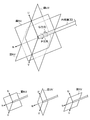
- FIG. 4 is an explanatory diagram of vectors defined for the endoscope 30.
- Three vectors N, U, and V are defined at the distal end of the endoscope 30.
- Vectors N, U, and V are vectors that are orthogonal to each other.
- the direction of the vector N is set to the protruding direction n (see FIG. 3) of the surgical instrument 34 of the endoscope 30.
- the vectors N, U and V define three planes NV, NU and UV. These planes NV, NU, and UV are planes defined as follows.
- Plane NV plane defined by vectors N and V
- Plane NU plane defined by vectors N and U
- Plane UV plane defined by vectors U and V
- the distal end of the endoscope 30 is configured to be able to rotate in the P direction and the Q direction about the vector N as a central axis.
- FIG. 5 shows the surfaces NV, NU, and UV when the distal end of the endoscope 30 is rotated.
- the MR apparatus 100 can perform the following scans during surgery. (1) Scan A for acquiring MR image of plane NV (2) Scan B for acquiring MR image of plane NU (3) Scan C for acquiring MR image of surface UV
- surgeons 12 and 13 arbitrarily select an MR image displayed on the display unit 10 from the MR image acquired by the scan A, the MR image acquired by the scan B, and the MR image acquired by the scan C. You can choose.
- FIG. 6 is a diagram schematically illustrating a state when the endoscope 30 is inserted into the animal 11.
- 6A is a diagram showing the positional relationship between the coordinate system CH set for the animal 11 and the vectors N, U, and V of the endoscope 30, and
- FIG. 6B is a diagram showing FIG. 6A. It is a figure when it sees from the direction of the vector N.
- FIG. In Figure 6, an example of a case where the rotation angle of the distal end of the endoscope 30 alpha is alpha alpha 0 is shown.
- a coordinate system CH (coordinate axes AP, RL, and SI) is set for the animal 11.
- the origins O 1 of the coordinate axes AP, RL, and SI are positioned, for example, at the isocenter of the magnet 2.
- the magnetic sensor 33 of the endoscope 30 detects a gradient magnetic field.
- the gradient magnetic field detected by the magnetic sensor 33 is transmitted to the control unit 8.
- the control unit 8 detects the position of the distal end of the endoscope 30 and the orientation of the distal end of the endoscope 30 based on the gradient magnetic field detected by the magnetic sensor 33. By detecting the position and orientation of the tip of the endoscope 30, the positions and orientations of the vectors N, U, and V can be detected.
- FIG. 6 (a) and 6 (b) schematically show a part G observed by the endoscope 30.
- FIG. A site G observed by the endoscope 30 is obtained as an endoscopic image.
- FIG. 7 is an explanatory diagram of an endoscopic image. As shown in FIG. 7A, the endoscopic image can be obtained as an image when the part G observed by the endoscope 30 is projected onto the surface UV. The vector U defines the upper side of the endoscopic image, and the vector V defines the left side of the endoscopic image.
- FIG. 8 is an explanatory diagram when an endoscopic image is displayed on the display unit 10.
- FIG. 9 schematically shows an example of an endoscopic image displayed on the display unit 10. An endoscopic image is displayed on the display unit 10 so that the vector U faces upward regardless of the rotation angle of the distal end of the endoscope 30.
- the display unit 10 displays coordinate information of the coordinate system CH (coordinate axes AP, RL, and SI) in addition to the endoscopic image.
- coordinate information of the coordinate system CH coordinate axes AP, RL, and SI
- FIG. 10 and 11 are explanatory diagrams when displaying the coordinate information of the coordinate system CH.
- the projection unit 81 (see FIG. 1) translates the vectors N, U, and V so that the origin O 1 of the coordinate system CH is positioned on the extension line of the vector N.
- FIG. 10B shows a diagram when FIG. 10A is viewed from the direction of the vector N.
- the projection unit 81 projects the coordinate axes AP, RL, and SI onto the endoscopic image (see FIG. 11).
- FIG. 11 is a diagram illustrating a state after the coordinate axes AP, RL, and SI are projected onto the endoscopic image.
- FIG. 11A is a diagram schematically illustrating a state when the coordinate axes AP, RL, and SI are projected onto the endoscopic image
- FIG. 11B is a view of FIG. It is a figure of time.
- the operator simply looks at the endoscopic image, and the lower side of the endoscopic image is the P-axis side (abdominal side). It is possible to easily visually recognize that the upper side of the endoscopic image is the A-axis side (back side). Therefore, the surgeon can use the information on the coordinate axes as a judgment material when determining the moving direction of the endoscope, and the burden on the surgeon can be reduced.
- FIG. 14 shows an example of an endoscopic image displayed on the display unit 10.
- the endoscopic image includes alphabets “A” and “P” representing the AP axis, alphabets “R” and “L” representing the RL axis, and SI axis.
- Alphabet “S” and “I” are shown. Therefore, it is possible to make it easier for the operator to see the endoscopic image.
- FIG. 14B circles surrounding the alphabets “A”, “P”, “R”, “L”, “S”, and “I” are added. By displaying such a circle, it is possible to make it easier for the operator to visually recognize the position of the central portion of the endoscopic image.
- FIG. 16A shows a view when FIG. 16A is viewed from the direction of the vector N.
- the coordinate axes AP, RL, and SI are projected onto the endoscopic image (see FIGS. 17 and 18).
- 17 and 18 are explanatory diagrams when the coordinate axes AP, RL, and SI are projected onto the endoscopic image.
- the projecting means 81 translates the vectors N, U, and V so that the origin O 1 of the coordinate system CH is positioned on the extension line of the vector N as shown in FIG.
- FIG. 17B shows a diagram when FIG. 17A is viewed from the direction of the vector N.
- the projection unit 81 projects the coordinate axes AP, RL, and SI onto the endoscopic image (see FIG. 18).
- FIG. 18 is a diagram illustrating a state after the coordinate axes AP, RL, and SI are projected onto the endoscopic image.
- 18A is a diagram schematically showing a state when the coordinate axes AP, RL, and SI are projected onto the endoscopic image
- FIG. 18B is a diagram of FIG. 18A viewed from the direction of the vector N. It is a figure of time.
- FIG. 20 schematically shows an example of an endoscopic image displayed on the display unit 10.
- FIG. 20A shows an example in which no circle is displayed
- 20B shows an example in which a circle is displayed. Since the coordinate axes AP, RL, and SI are projected on the endoscopic image, the operator simply looks at the endoscopic image, and the lower side of the endoscopic image is on the L-axis side (left half side). In addition, it can be easily visually recognized that the upper side of the endoscopic image is the R-axis side (right half side).
- all three coordinate axes AP, RL, and SI are displayed in the endoscopic image. However, it is not necessary to display all the three coordinate axes AP, RL, and SI. For example, only two coordinate axes may be displayed. Hereinafter, a case where only two coordinate axes are displayed will be described.
- FIG. 21 is an explanatory diagram when only two coordinate axes are displayed.
- the surgeon's line of sight is in the same direction as the vector N. Therefore, the operator knows the position of the distal end of the endoscope 30 more visually than the direction of the coordinate axis having a large angle with the vector N, rather than the direction of the coordinate axis having a small angle with the vector N. It is considered useful information for recognizing. Therefore, from among the three coordinate axes, the coordinate axis having the largest angle with the vector N and the coordinate axis having the second largest angle may be selected, and only the selected coordinate axis may be displayed (see FIG. 22).
- FIG. 22 is an explanatory diagram when a coordinate axis having a large angle with the vector N is selected from the three coordinate axes.
- the vectors N, U, and V of the endoscope 30 are translated so that the origin O 1 of the coordinate system CH is positioned on the extension line of the vector N.
- angles ⁇ 1, ⁇ 2, and ⁇ 3 formed by the vector N and the three coordinate axes AP, RL, and SI are defined.
- the selection means 82 calculates the angles ⁇ 1, ⁇ 2, and ⁇ 3. Therefore, by comparing the angles ⁇ 1, ⁇ 2, and ⁇ 3, it is possible to select the coordinate axis having the largest angle with the vector N and the second largest coordinate axis. For example, when there is a relationship of ⁇ 1> ⁇ 2> ⁇ 3 between the angles ⁇ 1, ⁇ 2, and ⁇ 3, the coordinate axis that makes the maximum angle with the vector N is AP, and the angle with the vector N is the second The larger coordinate axis is RL. Therefore, the two coordinate axes AP and RL are displayed.
- FIG. 23 shows an example in which two coordinate axes AP and RL are displayed on the endoscopic image. By displaying only two coordinate axes of the three coordinate axes with respect to the endoscopic image, only the coordinate axes having a high priority in displaying the position of the distal end of the endoscope 30 can be displayed. it can.
- FIG. 24 is a schematic diagram of an MR apparatus 200 of the second embodiment.
- the MR apparatus 200 includes a calculation unit 84 that calculates the elevation angle ⁇ of the endoscope 30.
- Other configurations are the same as those of the first embodiment.
- the elevation angle ⁇ will be described below.
- FIG. 25 is an explanatory diagram of the elevation angle ⁇ . Also in obtaining the elevation angle ⁇ , the vectors N, U, and V of the endoscope 30 are translated so that the vector N of the endoscope 30 crosses the origin O 1 of the coordinates, as in the first embodiment.
- FIG. 25 shows a surface RI defined by the SI axis and the RL axis.
- the elevation angle ⁇ is defined as the angle formed between the vector N and the projection component N0 of the vector N onto the surface RI.
- the elevation angle ⁇ is displayed on the display unit 10 by the display control means 83.
- FIG. 26 illustrates an example of a method for displaying the elevation angle ⁇ displayed on the display unit 10. In FIG.
- an elevation angle indicator Ie for indicating the elevation angle ⁇ is displayed at the center portion of the endoscopic image.
- the elevation angle indicator Ie has a pointer PT that indicates the value of the elevation angle ⁇ .
- the vector N faces obliquely upward with respect to the surface RI.
- the calculation means 84 is configured to calculate the azimuth angle ⁇ in addition to the elevation angle ⁇ , but the other configurations are the same as those in the second mode.
- the azimuth angle ⁇ will be described.
- FIG. 31 is an explanatory diagram of the azimuth angle ⁇ . Also in obtaining the azimuth angle ⁇ , the vectors N, U, and V of the endoscope 30 are translated so that the vector N of the endoscope 30 crosses the coordinate origin O 1 .
- the azimuth angle ⁇ is defined as the angle formed by the projection component N0 of the vector N onto the surface RI and the SI axis. This angle ⁇ is displayed on the display unit 10 by the display control means 83.
- FIG. 32 shows an example of a method for displaying the azimuth angle ⁇ displayed on the display unit 10. In FIG. 32, an azimuth angle indicator Ia for indicating the azimuth angle ⁇ is displayed above the circle in the endoscopic image.
- the azimuth indicator Ia has a pointer PT that indicates the value of the azimuth angle ⁇ .
- an alphabet “R” or “L” is written together with an angle representing ⁇ .
- the alphabet “R” indicates that the angle ⁇ is on the R axis side with respect to the SI axis
- the alphabet “L” indicates that the angle ⁇ is on the L axis side with respect to the SI axis.
- the display of the azimuth angle ⁇ changes when the value of the azimuth angle ⁇ is changed will be described.
- a surface AI is displayed in addition to the surface RI.
- the plane AI is a plane defined by the SI axis and the AP axis.
- FIG. 37 is a diagram showing a flow when performing surgery in the fourth embodiment.
- step ST1 a scan for acquiring image data of a surgical site is executed.
- FIG. 38 schematically shows the image data D acquired by scanning. After executing the scan, the process proceeds to step ST2.
- step ST2 the surgeon specifies a part (hereinafter referred to as “target”) where the surgical instrument 34 is desired to perform a surgical treatment while viewing the image data D.
- FIG. 39 shows the target T specified by the surgeon. After specifying the target T, the process proceeds to step ST3.
- FIG. 40 is a diagram schematically showing a state when the endoscope 30 is inserted into the animal 11.
- 40A is a diagram showing the positional relationship between the coordinate system CH set for the animal 11 and the vectors N, U, and V of the endoscope 30, and
- FIG. 40B is a diagram showing FIG. 40A. It is a figure when it sees from the direction of the vector N.
- FIG. 41 shows an example of an endoscopic image and various information displayed on the display unit 10.
- (1) to (6) are displayed on the display unit 10.
- (1) Endoscopic image (2) Coordinate axis (3) Elevation angle indicator Ie (4) Azimuth angle indicator Ia (5) Target T (6) Distances d, ⁇ , and ⁇ Since (1) to (4) have been described in the first to third embodiments, descriptions of (1) to (3) are omitted, and (5) and (6) are described below. To do.
- FIG. 42 is an explanatory diagram when the target T is displayed on the display unit 10.
- FIG. 42A is a diagram showing a state when the target T is projected onto the endoscopic image
- FIG. 42B is a diagram when FIG. 42A is viewed from the direction of the vector N.
- the projecting unit 81 projects the target T onto the endoscopic image. Thereby, the positional relationship between the endoscopic image and the target T can be obtained. Therefore, as shown in FIG. 41, the target T can be displayed in the endoscopic image.
- FIG. 43 is an explanatory diagram of the distances d, ⁇ , and ⁇ .
- the distance d is a distance from the tip of the endoscope 30 to the target T.
- the position of the tip of the endoscope 30 can be detected using the magnetic sensor 33 of the endoscope 30. Further, the position of the target T is obtained in step ST1. Therefore, since the position of the tip of the endoscope 30 and the position of the target T are known, the distance d can be calculated.
- the distance d is calculated by the calculation means 84.
- the distance ⁇ represents a virtual projecting distance of the surgical instrument 34 when it is assumed that the surgical instrument 34 is projected from the endoscope 30.
- the vectors U and V translate in the direction of the vector N by a distance ⁇ .
- the distance ⁇ is set by the operator.
- the distance ⁇ represents the length of the projection component when the distance g from the virtual tip position of the surgical instrument 34 to the target T is projected onto the vector N.
- the distance g can be calculated from the virtual tip position of the surgical instrument 34 and the position of the target T. Therefore, by projecting the distance g onto the vector N, the distance ⁇ can be calculated.
- the distance ⁇ is calculated by the calculation means 84.
- the display unit 10 also displays the target T, distances d, ⁇ , ⁇ , and the like.
- the surgeon looks at the display unit 10 (see FIG. 41), confirms the position of the target T, and determines whether or not the target T overlaps the center point C of the endoscopic image.
- the target T is shifted from the center point C of the endoscopic image. Therefore, the surgeon adjusts the position and orientation of the endoscope 30 so that the target T overlaps the center point C of the endoscopic image.
- FIG. 44 is a diagram schematically showing a state after the position and orientation of the endoscope 30 are adjusted.
- the vector N crosses the target T.
- the result is as follows.
- FIG. 45 is an explanatory diagram when the target T is projected onto an endoscopic image.
- 45A is a diagram showing a state when the target T is projected onto the endoscopic image
- FIG. 45B is a diagram when FIG. 45A is viewed from the direction of the vector N.
- FIG. When the vector N crosses the target T, the target N is projected on the center of the endoscopic image. Therefore, when the endoscopic image displayed on the display unit 10 is viewed, as shown in FIG. 46, the target T is displayed at the center point C of the endoscopic image.
- the surgeon sets a virtual protrusion distance ⁇ of the surgical instrument 34 (see FIG. 47).
- the calculation unit 84 calculates the distance ⁇ and the like.
- the MR apparatus executes a scan for acquiring an MR image of the surface UV.
- the MR image of the surface UV acquired by this scan is displayed on the display unit 10 together with the endoscopic image.
- FIG. 48 shows an example of an image displayed on the display unit 10.
- FIG. 49 is a diagram showing a state when the surgeon sets ⁇ to another value.
- the virtual tip position of the surgical instrument 34 has reached the target T.
- the MR apparatus executes a scan for acquiring an MR image of the surface UV.
- an image as shown in FIG. 50 is displayed on the display unit 10.
- the operator can confirm the target T in the MR image of the surface UV. it can.
- the surgeon changes the value of ⁇ and confirms the MR image of the surface UV obtained for each value of ⁇ .
- the operator can confirm information such as the position, size, and shape of the target T.
- the surgical instrument 34 is actually protruded from the distal end of the endoscope 30, and a surgical treatment is performed on the target T to perform treatment.
- the surgeon can confirm the positional relationship between the endoscopic image and the target T by looking at the display unit 10. Moreover, since the distance from the virtual tip position of the surgical instrument 34 to the target T can be known by calculating the distance ⁇ , it can be used as a reference when the operator sets the value of ⁇ .
- FIG. 51 shows an example in which an MR image of surface UV, an MR image of surface NU, and an MR image of surface NV are displayed.
- the magnetic resonance apparatus is described.
- the present invention can be applied to a medical apparatus (for example, a CT apparatus) different from the magnetic resonance apparatus as long as the medical apparatus has a display device that displays an endoscopic image.
- the object observed by the endoscope is not limited to animals, and an object other than a human body or a living thing (for example, the inside of a pipe or the inside of a building) can be viewed with an endoscope. It can be the object to be observed.
Landscapes
- Health & Medical Sciences (AREA)
- Life Sciences & Earth Sciences (AREA)
- Surgery (AREA)
- Engineering & Computer Science (AREA)
- Physics & Mathematics (AREA)
- Radiology & Medical Imaging (AREA)
- Medical Informatics (AREA)
- Veterinary Medicine (AREA)
- Biophysics (AREA)
- Nuclear Medicine, Radiotherapy & Molecular Imaging (AREA)
- Optics & Photonics (AREA)
- Pathology (AREA)
- Public Health (AREA)
- General Health & Medical Sciences (AREA)
- Biomedical Technology (AREA)
- Heart & Thoracic Surgery (AREA)
- Animal Behavior & Ethology (AREA)
- Molecular Biology (AREA)
- General Physics & Mathematics (AREA)
- Theoretical Computer Science (AREA)
- Multimedia (AREA)
- Signal Processing (AREA)
- Computer Vision & Pattern Recognition (AREA)
- Endoscopes (AREA)
- Instruments For Viewing The Inside Of Hollow Bodies (AREA)
- Magnetic Resonance Imaging Apparatus (AREA)
Abstract
【課題】内視鏡を操作する術者の負担を軽減する。 【解決手段】 投影手段81は、内視鏡30に規定されているベクトルNの延長線上に座標系CHの原点O1が位置するように、ベクトルN、U、およびVを平行移動する。ベクトルN、U、およびVを平行移動した後、投影手段81は、座標軸AP、RL、およびSIを内視鏡画像に投影する。そして、投影された座標軸AP、RL、およびSIを、内視鏡画像とともに、表示部10に表示する。術者は、表示部10に表示された内視鏡画像を見ることによって、座標軸AP、RL、およびSIの情報を確認することができる。
Description
本発明は、内視鏡画像を表示する表示装置、この表示装置を有する医用装置、内視鏡画像を表示する表示方法、および表示装置に用いられるプログラムに関する。
近年、内視鏡で患者の体内を観察しながら、医用装置(MR装置、CT装置など)で患者を撮影し、内視鏡画像と医用画像(MR画像やCT画像)とを見ながら手術する方法が知られている(特許文献1参照)。
しかし、一般的に、内視鏡の視野は狭いので、術者が内視鏡画像から視認できる範囲は限られている。したがって、術者は、視認できる範囲が限られた条件下で、内視鏡の移動方向などを決める必要があり、術者に大きな負担が掛かる。このような理由から、内視鏡を操作する術者の負担を軽減することが望まれている。
本発明の第1の観点は、対象を観察する内視鏡により得られた内視鏡画像を表示する表示装置であって、
前記対象に対して設定された座標軸を、前記内視鏡画像に投影する投影手段と、
前記内視鏡画像と、前記内視鏡画像に投影された前記座標軸とを表示する表示部と、を有する表示装置である。
前記対象に対して設定された座標軸を、前記内視鏡画像に投影する投影手段と、
前記内視鏡画像と、前記内視鏡画像に投影された前記座標軸とを表示する表示部と、を有する表示装置である。
本発明の第2の観点は、第1の観点の表示装置を有する医用装置である。
本発明の第3の観点は、対象を観察する内視鏡により得られた内視鏡画像を表示する表示方法であって、
前記対象に対して設定された座標軸を、前記内視鏡画像に投影する投影ステップと、
前記内視鏡画像と、前記内視鏡画像に投影された前記座標軸とを表示する表示ステップと、を有する表示方法である。
前記対象に対して設定された座標軸を、前記内視鏡画像に投影する投影ステップと、
前記内視鏡画像と、前記内視鏡画像に投影された前記座標軸とを表示する表示ステップと、を有する表示方法である。
本発明の第4の観点は、対象を観察する内視鏡により得られた内視鏡画像を表示する表示部を備えた表示装置のプログラムであって、
前記対象に対して設定された座標軸を、前記内視鏡画像に投影する投影処理と、
前記表示部に、前記内視鏡画像と、前記内視鏡画像に投影された前記座標軸とを表示させる表示制御処理と、
を計算機に実行させるためのプログラムである。
前記対象に対して設定された座標軸を、前記内視鏡画像に投影する投影処理と、
前記表示部に、前記内視鏡画像と、前記内視鏡画像に投影された前記座標軸とを表示させる表示制御処理と、
を計算機に実行させるためのプログラムである。
表示部には、内視鏡画像に投影された座標軸が表示される。したがって、術者は、内視鏡画像に表示されている部位と座標軸との対応関係を容易に認識することができる。
以下、発明を実施するための形態について説明するが、本発明は、以下の形態に限定されることはない。
(1)第1の形態
図1は、本発明の第1の形態の磁気共鳴装置の概略図である。
磁気共鳴装置(以下、「MR装置」と呼ぶ。MR:Magnetic Resonance)100は、マグネット2、テーブル3、受信コイル4などを有している。
図1は、本発明の第1の形態の磁気共鳴装置の概略図である。
磁気共鳴装置(以下、「MR装置」と呼ぶ。MR:Magnetic Resonance)100は、マグネット2、テーブル3、受信コイル4などを有している。
マグネット2はボア21を有している。また、マグネット2には、超伝導コイル、勾配コイル、およびRFコイルなどが内蔵されている。超伝導コイルは静磁場を印加し、勾配コイルは勾配磁場を印加し、RFコイルはRFパルスを送信する。
テーブル3はクレードル3aを有している。クレードル3aは、ボア21内に移動できるように構成されている。クレードル3aには、手術を受ける動物11が寝かされている。動物11には内視鏡30が挿入されている。術者12および13は、内視鏡30を操作しながら動物11の手術を行う。
受信コイル4は、動物11に取り付けられている。受信コイル4は、動物11からの磁気共鳴信号を受信する。
MR装置100は、更に、送信器5、勾配磁場電源6、受信器7、制御部8、操作部9、および表示部10などを有している。
送信器5はRFコイルに電流を供給し、勾配磁場電源6は勾配コイルに電流を供給する。
受信器7は、受信コイル4から受け取った信号に対して、検波などの信号処理を実行する。
受信器7は、受信コイル4から受け取った信号に対して、検波などの信号処理を実行する。
制御部8は、受信器7から受け取ったデータに基づいて画像を再構成するなど、MR装置100の各種の動作を実現するように、MR装置100の各部の動作を制御する。制御部8は、投影手段81、選択手段82、および表示制御手段83などを有している。
投影手段81は、座標軸AP、RL、およびSI(例えば、図6参照)を、内視鏡30により取得された内視鏡画像に投影する。
選択手段82は、座標軸AP、RL、およびSIの中から、内視鏡画像に重ねて表示する座標軸を選択する。
表示制御手段83は表示部10を制御する。
選択手段82は、座標軸AP、RL、およびSIの中から、内視鏡画像に重ねて表示する座標軸を選択する。
表示制御手段83は表示部10を制御する。
制御部8は、投影手段81、選択手段82、および表示制御手段83を構成する一例であり、所定のプログラムを実行することにより、これらの手段として機能する。
操作部9は、オペレータにより操作され、種々の情報を制御部8に入力する。表示部10は、内視鏡30により得られた内視鏡画像などを表示する。尚、表示部10および制御部8を合わせたものが、表示装置の一例である。
MR装置100は、上記のように構成されている。
MR装置100は、上記のように構成されている。
次に、内視鏡30について説明する。
図2は内視鏡30の構造の説明図である。
図2(a)は内視鏡30の外観図、図2(b)は内視鏡30の先端の正面図である。
図2は内視鏡30の構造の説明図である。
図2(a)は内視鏡30の外観図、図2(b)は内視鏡30の先端の正面図である。
内視鏡30には、光源31、光ファイバ32、磁気センサ33、および外科用器具34などが設けられている。磁気センサ33は、勾配磁場を検出し、内視鏡30の先端の位置および内視鏡30の先端の向きを求める。外科用器具34は、動物11の外科的治療を行うための器具であり、内視鏡30の先端から突出させることができるように構成されている。図3に、外科用器具34を内視鏡30の先端から突出させたときの様子を示す。術者は内視鏡30の操作部を操作することにより、外科用器具34を内視鏡30の先端から所定の方向nに突出させることができる。
また、内視鏡30には、ベクトルが規定されている(図4および図5参照)。
図4は、内視鏡30に対して規定されているベクトルの説明図である。
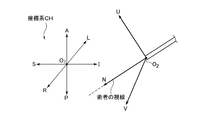
内視鏡30の先端には、3つのベクトルN、ベクトルU、およびベクトルVが規定されている。ベクトルN、U、およびVは互いに直交するベクトルである。ベクトルNの方向は、内視鏡30の外科用器具34の突出方向n(図3参照)に設定されている。ベクトルN、U、およびVによって、3つの面NV、NU、およびUVが規定されている。これらの面NV、NU、およびUVは、以下のように規定される面である。
面NV:ベクトルNおよびVによって規定される面
面NU:ベクトルNおよびUによって規定される面
面UV:ベクトルUおよびVによって規定される面
図4は、内視鏡30に対して規定されているベクトルの説明図である。
内視鏡30の先端には、3つのベクトルN、ベクトルU、およびベクトルVが規定されている。ベクトルN、U、およびVは互いに直交するベクトルである。ベクトルNの方向は、内視鏡30の外科用器具34の突出方向n(図3参照)に設定されている。ベクトルN、U、およびVによって、3つの面NV、NU、およびUVが規定されている。これらの面NV、NU、およびUVは、以下のように規定される面である。
面NV:ベクトルNおよびVによって規定される面
面NU:ベクトルNおよびUによって規定される面
面UV:ベクトルUおよびVによって規定される面
内視鏡30の先端は、ベクトルNを中心軸としてP方向およびQ方向に回転させることができるように構成されている。図5に、内視鏡30の先端を回転させたときの面NV、NU、およびUVを示す。
図5(a)は、内視鏡30の先端をベクトルNを中心としてP方向に角度α=α0だけ回転させたときの面NV、NU、およびUVを示す図であり、図5(b)は、図5(a)をベクトルNの方向から見たときの図である。
内視鏡30の先端をP方向(又はQ方向)に回転させることにより、面NV、NU、およびUVもベクトルNを中心として回転させることができる。
MR装置100は、手術の間、以下のスキャンを実行することができる。
(1)面NVのMR画像を取得するためのスキャンA
(2)面NUのMR画像を取得するためのスキャンB
(3)面UVのMR画像を取得するためのスキャンC
MR装置100は、手術の間、以下のスキャンを実行することができる。
(1)面NVのMR画像を取得するためのスキャンA
(2)面NUのMR画像を取得するためのスキャンB
(3)面UVのMR画像を取得するためのスキャンC
術者12および13は、スキャンAにより取得されるMR画像、スキャンBにより取得されるMR画像、およびスキャンCにより取得されるMR画像の中から、表示部10に表示されるMR画像を任意に選択することができる。
以下に、術者12および13が内視鏡30を用いて動物11の手術をするときの手順について説明する。
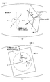
図6は、内視鏡30を動物11に挿入したときの様子を概略的に示す図である。
図6(a)は、動物11に設定された座標系CHと、内視鏡30のベクトルN、U、およびVとの位置関係を示す図、図6(b)は図6(a)をベクトルNの方向から見たときの図である。図6では、内視鏡30の先端の回転角αがα=α0の場合の例が示されている。
図6(a)は、動物11に設定された座標系CHと、内視鏡30のベクトルN、U、およびVとの位置関係を示す図、図6(b)は図6(a)をベクトルNの方向から見たときの図である。図6では、内視鏡30の先端の回転角αがα=α0の場合の例が示されている。
動物11には座標系CH(座標軸AP、RL、およびSI)が設定されている。座標軸AP、RL、およびSIの原点O1は、例えば、マグネット2のアイソセンターに位置決めされている。
内視鏡30の磁気センサ33は勾配磁場を検出する。磁気センサ33により検出された勾配磁場は、制御部8に送信される。制御部8では、磁気センサ33により検出された勾配磁場に基づいて、内視鏡30の先端の位置および内視鏡30の先端の向きを検出する。内視鏡30の先端の位置および向きを検出することにより、ベクトルN、U、およびVの位置および向きを検出することができる。
また、図6(a)および(b)には、内視鏡30により観察される部位Gを概略的に示してある。内視鏡30により観察される部位Gが、内視鏡画像として得られる。
図7は、内視鏡画像の説明図である。
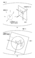
内視鏡画像は、図7(a)に示すように、内視鏡30により観察される部位Gを面UVに投影したときの画像として得ることができる。ベクトルUは内視鏡画像の上側を規定しており、ベクトルVは内視鏡画像の左側を規定している。図7(b)には、図7(a)をベクトルNの方向から見たときの図が示されている。内視鏡30の先端はα=α0だけ回転しているので(図6参照)、内視鏡画像もα=α0だけ傾いている。内視鏡画像は、表示制御手段83により、表示部10(図1参照)に表示される。
図7は、内視鏡画像の説明図である。
内視鏡画像は、図7(a)に示すように、内視鏡30により観察される部位Gを面UVに投影したときの画像として得ることができる。ベクトルUは内視鏡画像の上側を規定しており、ベクトルVは内視鏡画像の左側を規定している。図7(b)には、図7(a)をベクトルNの方向から見たときの図が示されている。内視鏡30の先端はα=α0だけ回転しているので(図6参照)、内視鏡画像もα=α0だけ傾いている。内視鏡画像は、表示制御手段83により、表示部10(図1参照)に表示される。
図8は、内視鏡画像を表示部10に表示するときの説明図である。
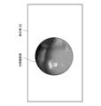
内視鏡30の先端がα=α0だけ回転している場合、得られる内視鏡画像も、α=α0だけ回転している(図8(a)参照)。そこで、内視鏡画像の回転角を元に戻すために、ベクトルの原点O2を中心として内視鏡画像を時計方向にα0だけ回転させる(図8(b)参照)。これにより、ベクトルUが上側を向き、ベクトルVが左側を向くようにすることができる。このように内視鏡画像を回転させた後で、内視鏡画像を表示部10に表示する。図9に、表示部10に表示された内視鏡画像の一例を概略的に示す。内視鏡30の先端の回転角に関わらず、表示部10には、ベクトルUが上側を向くように内視鏡画像が表示される。
内視鏡30の先端がα=α0だけ回転している場合、得られる内視鏡画像も、α=α0だけ回転している(図8(a)参照)。そこで、内視鏡画像の回転角を元に戻すために、ベクトルの原点O2を中心として内視鏡画像を時計方向にα0だけ回転させる(図8(b)参照)。これにより、ベクトルUが上側を向き、ベクトルVが左側を向くようにすることができる。このように内視鏡画像を回転させた後で、内視鏡画像を表示部10に表示する。図9に、表示部10に表示された内視鏡画像の一例を概略的に示す。内視鏡30の先端の回転角に関わらず、表示部10には、ベクトルUが上側を向くように内視鏡画像が表示される。
また、本形態では、表示部10には、内視鏡画像の他に、座標系CH(座標軸AP、RL、およびSI)の座標情報も表示される。以下に、座標情報がどのようにして表示されるかについて説明する。
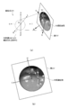
図10および図11は、座標系CHの座標情報を表示するときの説明図である。
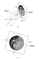
投影手段81(図1参照)は、図10(a)に示すように、ベクトルNの延長線上に座標系CHの原点O1が位置するように、ベクトルN、U、およびVを平行移動する。図10(b)には、図10(a)をベクトルNの方向から見たときの図が示されている。ベクトルN、U、およびVを平行移動した後、投影手段81は、座標軸AP、RL、およびSIを内視鏡画像に投影する(図11参照)。
投影手段81(図1参照)は、図10(a)に示すように、ベクトルNの延長線上に座標系CHの原点O1が位置するように、ベクトルN、U、およびVを平行移動する。図10(b)には、図10(a)をベクトルNの方向から見たときの図が示されている。ベクトルN、U、およびVを平行移動した後、投影手段81は、座標軸AP、RL、およびSIを内視鏡画像に投影する(図11参照)。
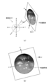
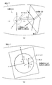
図11は、座標軸AP、RL、およびSIを内視鏡画像に投影した後の様子を示す図である。図11(a)は座標軸AP、RL、およびSIを内視鏡画像に投影するときの様子を概略的に示す図、図11(b)は図11(a)をベクトルNの方向から見たときの図である。
座標軸AP、RL、およびSIを内視鏡画像に投影することによって、座標軸AP、RL、およびSIと、内視鏡画像に表示される部位との対応関係を求めることができる。投影された座標軸AP、RL、およびSIは、表示制御手段83により、内視鏡画像とともに、表示部10に表示される(図12参照)。
座標軸AP、RL、およびSIを内視鏡画像に投影することによって、座標軸AP、RL、およびSIと、内視鏡画像に表示される部位との対応関係を求めることができる。投影された座標軸AP、RL、およびSIは、表示制御手段83により、内視鏡画像とともに、表示部10に表示される(図12参照)。
図12は、座標軸AP、RL、およびSIおよび内視鏡画像を表示部10に表示するときの説明図である。
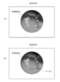
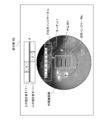
内視鏡画像はα=α0だけ回転しているので(図12(a)参照)、内視鏡画像の回転角を元に戻すために、ベクトルの原点O2を中心として内視鏡画像を時計方向にα0だけ回転させる(図12(b)参照)。これにより、ベクトルUが上側を向き、ベクトルVが左側を向くようにすることができる。このように内視鏡画像を回転させた後で、内視鏡画像を表示部10に表示する。図13に、表示部10に表示された内視鏡画像の一例を概略的に示す。内視鏡画像には、座標軸AP、RL、およびSIが投影されているので、術者は、内視鏡画像を見るだけで、内視鏡画像の下側がP軸側(腹部側)であり、内視鏡画像の上側がA軸側(背中側)であることを視覚的に容易に認識することができる。したがって、術者は、座標軸の情報を、内視鏡の移動方向などを決めるときの判断材料として使用することができ、術者の負担を軽減することができる。
内視鏡画像はα=α0だけ回転しているので(図12(a)参照)、内視鏡画像の回転角を元に戻すために、ベクトルの原点O2を中心として内視鏡画像を時計方向にα0だけ回転させる(図12(b)参照)。これにより、ベクトルUが上側を向き、ベクトルVが左側を向くようにすることができる。このように内視鏡画像を回転させた後で、内視鏡画像を表示部10に表示する。図13に、表示部10に表示された内視鏡画像の一例を概略的に示す。内視鏡画像には、座標軸AP、RL、およびSIが投影されているので、術者は、内視鏡画像を見るだけで、内視鏡画像の下側がP軸側(腹部側)であり、内視鏡画像の上側がA軸側(背中側)であることを視覚的に容易に認識することができる。したがって、術者は、座標軸の情報を、内視鏡の移動方向などを決めるときの判断材料として使用することができ、術者の負担を軽減することができる。
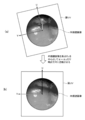
尚、図13では、座標軸AP、RL、およびSIを表す矢印が示されている。しかし、これらの矢印は、内視鏡画像に重なっているので、術者が内視鏡画像を視認する上では邪魔になる。そこで、表示部10に内視鏡画像を表示するときは、これらの矢印は表示しないようにする。図14に、表示部10に表示される内視鏡画像の例を示す。図14(a)では、矢印は表示されておらず、内視鏡画像には、AP軸を表すアルファベット「A」および「P」、RL軸を表すアルファベット「R」および「L」、SI軸を表すアルファベット「S」および「I」が示されている。したがって、術者に内視鏡画像を見易くさせることができる。
一方、図14(b)では、アルファベット「A」、「P」、「R」、「L」、「S」、および「I」を取り囲むようなサークルが追加されている。このようなサークルを表示することによって、術者に、内視鏡画像の中央部分の領域の位置を視覚的に認識しやすくさせることができる。
次に、内視鏡30の先端の角度αを変化させた場合、AP軸、RL軸、およびSI軸の表示がどのように変化するかについて説明する。
図15は内視鏡30の先端の回転角αをα0からα1に変更したときの座標系CHとベクトルN、U、およびVとの位置関係を示す図、図16はα=α1の場合に取得される内視鏡画像の説明図である。
内視鏡30の先端の回転角を変更しても、内視鏡30により観察される部位Gに変化はない。したがって、図16(a)に示すように、α=α1の場合も、α=α0の場合と同様に、部位Gを面UVに投影したときの画像が、内視鏡画像として得られる。図16(b)には、図16(a)をベクトルNの方向から見たときの図が示されている。
次に、内視鏡画像に、座標軸AP、RL、およびSIを投影する(図17および図18参照)。
図17および図18は、内視鏡画像に座標軸AP、RL、およびSIを投影するときの説明図である。
投影手段81は、先ず、図17(a)に示すように、ベクトルNの延長線上に座標系CHの原点O1が位置するように、ベクトルN、U、およびVを平行移動する。図17(b)には、図17(a)をベクトルNの方向から見たときの図が示されている。ベクトルN、U、およびVを平行移動した後、投影手段81は、座標軸AP、RL、およびSIを内視鏡画像に投影する(図18参照)。
図17および図18は、内視鏡画像に座標軸AP、RL、およびSIを投影するときの説明図である。
投影手段81は、先ず、図17(a)に示すように、ベクトルNの延長線上に座標系CHの原点O1が位置するように、ベクトルN、U、およびVを平行移動する。図17(b)には、図17(a)をベクトルNの方向から見たときの図が示されている。ベクトルN、U、およびVを平行移動した後、投影手段81は、座標軸AP、RL、およびSIを内視鏡画像に投影する(図18参照)。
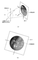
図18は、座標軸AP、RL、およびSIを内視鏡画像に投影した後の様子を示す図である。図18(a)は座標軸AP、RL、およびSIを内視鏡画像に投影するときの様子を概略的に示す図、図18(b)は図18(a)をベクトルNの方向から見たときの図である。
座標軸AP、RL、およびSIを内視鏡画像に投影することによって、座標軸AP、RL、およびSIと、内視鏡画像に表示される部位との対応関係を求めることができる。投影された座標軸AP、RL、およびSIは、表示制御手段83により、内視鏡画像とともに、表示部10に表示される(図19参照)。
座標軸AP、RL、およびSIを内視鏡画像に投影することによって、座標軸AP、RL、およびSIと、内視鏡画像に表示される部位との対応関係を求めることができる。投影された座標軸AP、RL、およびSIは、表示制御手段83により、内視鏡画像とともに、表示部10に表示される(図19参照)。
図19は、座標軸AP、RL、およびSIおよび内視鏡画像を表示部10に表示するときの説明図である。
内視鏡画像はα=α1だけ回転しているので(図19(a)参照)、内視鏡画像の回転角を元に戻すために、ベクトルの原点O2を中心として内視鏡画像を時計方向にα0だけ回転させる(図19(b)参照)。これにより、ベクトルUが上側を向き、ベクトルVが左側を向くようにすることができる。このように内視鏡画像を回転させた後で、内視鏡画像を表示部10に表示する。図20に、表示部10に表示された内視鏡画像の一例を概略的に示す。図20(a)はサークルが表示されない例を示し、図20(b)はサークルが表示される例を示す。内視鏡画像には、座標軸AP、RL、およびSIが投影されているので、術者は、内視鏡画像を見るだけで、内視鏡画像の下側がL軸側(左半身側)であり、内視鏡画像の上側がR軸側(右半身側)であることを視覚的に容易に認識することができる。
内視鏡画像はα=α1だけ回転しているので(図19(a)参照)、内視鏡画像の回転角を元に戻すために、ベクトルの原点O2を中心として内視鏡画像を時計方向にα0だけ回転させる(図19(b)参照)。これにより、ベクトルUが上側を向き、ベクトルVが左側を向くようにすることができる。このように内視鏡画像を回転させた後で、内視鏡画像を表示部10に表示する。図20に、表示部10に表示された内視鏡画像の一例を概略的に示す。図20(a)はサークルが表示されない例を示し、図20(b)はサークルが表示される例を示す。内視鏡画像には、座標軸AP、RL、およびSIが投影されているので、術者は、内視鏡画像を見るだけで、内視鏡画像の下側がL軸側(左半身側)であり、内視鏡画像の上側がR軸側(右半身側)であることを視覚的に容易に認識することができる。
尚、上記の説明では、内視鏡画像に、3つの座標軸AP、RL、およびSIが全て表示されている。しかし、3つの座標軸AP、RL、およびSIを全て表示する必要はなく、例えば、2つの座標軸のみを表示してもよい。以下に、2つの座標軸のみを表示する場合について説明する。
図21は、2つの座標軸のみを表示するときの説明図である。
術者が内視鏡画像を見ると、術者の視線はベクトルNと同一方向になる。したがって、術者としては、ベクトルNとの成す角が小さい座標軸の方向を知るよりも、ベクトルNとの成す角が大きい座標軸の方向を知る方が、内視鏡30の先端の位置を視覚的に認識する上では有用な情報であると考えられる。そこで、3つの座標軸の中から、ベクトルNとの成す角度が1番大きい座標軸と2番目に大きい座標軸を選択し、選択された座標軸のみを表示させてもよい(図22参照)。
術者が内視鏡画像を見ると、術者の視線はベクトルNと同一方向になる。したがって、術者としては、ベクトルNとの成す角が小さい座標軸の方向を知るよりも、ベクトルNとの成す角が大きい座標軸の方向を知る方が、内視鏡30の先端の位置を視覚的に認識する上では有用な情報であると考えられる。そこで、3つの座標軸の中から、ベクトルNとの成す角度が1番大きい座標軸と2番目に大きい座標軸を選択し、選択された座標軸のみを表示させてもよい(図22参照)。
図22は、3つの座標軸の中から、ベクトルNとの成す角度が大きい座標軸を選択するときの説明図である。
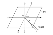
先ず、ベクトルNの延長線上に座標系CHの原点O1が位置するように内視鏡30のベクトルN、U、およびVを平行移動する。このようにベクトルN、U、およびVを平行移動することにより、ベクトルNと3つの座標軸AP、RL、およびSIとの成す角β1、β2、およびβ3が規定される。
先ず、ベクトルNの延長線上に座標系CHの原点O1が位置するように内視鏡30のベクトルN、U、およびVを平行移動する。このようにベクトルN、U、およびVを平行移動することにより、ベクトルNと3つの座標軸AP、RL、およびSIとの成す角β1、β2、およびβ3が規定される。
選択手段82(図1参照)は、角β1、β2、およびβ3を計算する。したがって、角β1、β2、およびβ3を比較することにより、ベクトルNとの成す角度が1番大きい座標軸と2番目に大きい座標軸を選択することができる。例えば、角β1、β2、およびβ3の間に、β1>β2>β3の関係がある場合、ベクトルNとの成す角が最大となる座標軸は、APであり、ベクトルNとの成す角が2番目に大きい座標軸は、RLとなる。したがって、2つの座標軸APおよびRLを表示する。図23に、内視鏡画像に2つの座標軸APおよびRLを表示した例を示す。内視鏡画像に対して、3つの座標軸のうち、2つの座標軸のみを表示することにより、術者が内視鏡30の先端の位置を知る上で優先順位の高い座標軸のみを表示することができる。
(2)第2の形態
図24は、第2の形態のMR装置200の概略図である。
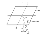
MR装置200は、内視鏡30の仰角θを算出する算出手段84を有している。尚、その他の構成は、第1の形態と同じである。以下に、仰角θについて説明する。
図24は、第2の形態のMR装置200の概略図である。
MR装置200は、内視鏡30の仰角θを算出する算出手段84を有している。尚、その他の構成は、第1の形態と同じである。以下に、仰角θについて説明する。
図25は、仰角θの説明図である。
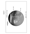
仰角θを求める場合も、第1の形態と同様に、内視鏡30のベクトルNが座標の原点O1を横切るように、内視鏡30のベクトルN、U、およびVを平行移動する。図25には、SI軸とRL軸とによって規定される面RIが示されている。仰角θは、ベクトルNの面RIへの投影成分N0とベクトルNとの成す角度として規定される。仰角θは、表示制御手段83により、表示部10に表示される。図26に、表示部10に表示される仰角θの表示方法の一例を示す。図26では、内視鏡画像の中央部分に、仰角θを示すための仰角インジケータIeが表示されている。仰角インジケータIeは、仰角θの値を指示するポインタPTを有している。図26では、仰角インジケータIeは、10°~70°の角度範囲を示し、ポインタが、θ=45°を指示している例が示されている。したがって、術者は、表示部10に表示された内視鏡画像を見ながら、同時に、仰角θ(θ=45°)を確認することができるので、内視鏡30の先端が面RIに対してどの程度傾いているかを知ることができる。
次に、仰角θの値を変化させた場合、仰角θの表示がどのように変化するかについて説明する。
仰角θを求める場合も、第1の形態と同様に、内視鏡30のベクトルNが座標の原点O1を横切るように、内視鏡30のベクトルN、U、およびVを平行移動する。図25には、SI軸とRL軸とによって規定される面RIが示されている。仰角θは、ベクトルNの面RIへの投影成分N0とベクトルNとの成す角度として規定される。仰角θは、表示制御手段83により、表示部10に表示される。図26に、表示部10に表示される仰角θの表示方法の一例を示す。図26では、内視鏡画像の中央部分に、仰角θを示すための仰角インジケータIeが表示されている。仰角インジケータIeは、仰角θの値を指示するポインタPTを有している。図26では、仰角インジケータIeは、10°~70°の角度範囲を示し、ポインタが、θ=45°を指示している例が示されている。したがって、術者は、表示部10に表示された内視鏡画像を見ながら、同時に、仰角θ(θ=45°)を確認することができるので、内視鏡30の先端が面RIに対してどの程度傾いているかを知ることができる。
次に、仰角θの値を変化させた場合、仰角θの表示がどのように変化するかについて説明する。
図27は、内視鏡30の先端の仰角θがθ=0°のときの座標系CHとベクトルNとの位置関係を示す図、図28は、θ=0°のときの仰角インジケータIeの一例を示す図である。
θ=0°の場合、ベクトルNは面RIに対して平行になる。仰角インジケータIeは、-30°~30°の角度範囲を示し、ポインタはθ=0°を指示している。したがって、術者は、表示部10に表示された内視鏡画像を見ながら、同時に、仰角θ(θ=0°)を確認することができるので、内視鏡30のベクトルNが面RIに平行であることを認識できる。
次に、内視鏡30の先端の仰角θがθ=-45°の場合の仰角インジケータについて説明する。
次に、内視鏡30の先端の仰角θがθ=-45°の場合の仰角インジケータについて説明する。
図29は、内視鏡30の先端の仰角θがθ=-45°のときの座標系CHとベクトルNとの位置関係を示す図、図30は、θ=-45°のときの仰角インジケータIeの一例を示す図である。
θ=-45°の場合、ベクトルNは面RIに対して斜め上方向を向く。仰角インジケータは、-10°~-70°の角度範囲を示し、ポインタはθ=-45°を指示している。したがって、術者は、表示部10に表示された内視鏡画像を見ながら、同時に、仰角θの値(θ=-45°)を確認することができるので、内視鏡30の先端は斜め上の方向を向いていることを認識できる。
(3)第3の形態
以下に、第3の形態について説明する。第3の形態では、算出手段84が、仰角θの他に、方位角φを算出するように構成されているが、その他の構成は、第2の形態と同じである。以下に、方位角φについて説明する。
以下に、第3の形態について説明する。第3の形態では、算出手段84が、仰角θの他に、方位角φを算出するように構成されているが、その他の構成は、第2の形態と同じである。以下に、方位角φについて説明する。
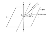
図31は、方位角φの説明図である。
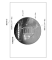
方位角φを求める場合も、内視鏡30のベクトルNが座標の原点O1を横切るように、内視鏡30のベクトルN、U、およびVを平行移動する。方位角φは、ベクトルNの面RIへの投影成分N0とSI軸との成す角として規定される。この角度φが、表示制御手段83により、表示部10に表示される。図32に、表示部10に表示される方位角φの表示方法の一例を示す。図32では、内視鏡画像内のサークルの上部に、方位角φを示すための方位角インジケータIaが表示されている。方位角インジケータIaは、方位角φの値を指示するポインタPTを有している。図32では、方位角インジケータIaは、50°R~10°Lの角度範囲を示し、ポインタPTが、φ=20°Rを指示している例が示されている。尚、φを表す角度には、アルファベット「R」又は「L」が併記されている。アルファベット「R」は、角度φがSI軸に対してR軸側であることを示しており、アルファベット「L」は、角度φがSI軸に対してL軸側であることを示している。したがって、ポインタPTが指示しているφ=20°Rは、SI軸に対してR軸側に20°傾いていることを表している。術者は、表示部10に表示された内視鏡画像を見ながら、同時に、方位角φ(θ=20°R)を確認することができるので、内視鏡30の先端がSI軸に対してどの程度傾いているかを知ることができる。
次に、方位角φの値を変化させた場合、方位角φの表示がどのように変化するかについて説明する。
方位角φを求める場合も、内視鏡30のベクトルNが座標の原点O1を横切るように、内視鏡30のベクトルN、U、およびVを平行移動する。方位角φは、ベクトルNの面RIへの投影成分N0とSI軸との成す角として規定される。この角度φが、表示制御手段83により、表示部10に表示される。図32に、表示部10に表示される方位角φの表示方法の一例を示す。図32では、内視鏡画像内のサークルの上部に、方位角φを示すための方位角インジケータIaが表示されている。方位角インジケータIaは、方位角φの値を指示するポインタPTを有している。図32では、方位角インジケータIaは、50°R~10°Lの角度範囲を示し、ポインタPTが、φ=20°Rを指示している例が示されている。尚、φを表す角度には、アルファベット「R」又は「L」が併記されている。アルファベット「R」は、角度φがSI軸に対してR軸側であることを示しており、アルファベット「L」は、角度φがSI軸に対してL軸側であることを示している。したがって、ポインタPTが指示しているφ=20°Rは、SI軸に対してR軸側に20°傾いていることを表している。術者は、表示部10に表示された内視鏡画像を見ながら、同時に、方位角φ(θ=20°R)を確認することができるので、内視鏡30の先端がSI軸に対してどの程度傾いているかを知ることができる。
次に、方位角φの値を変化させた場合、方位角φの表示がどのように変化するかについて説明する。
図33は、内視鏡30の先端の方位角φがφ=0°のときの座標系CHとベクトルNとの位置関係を示す図、図34は、φ=0°のときの方位角インジケータIaの一例を示す図である。
図33には、面RIの他に、面AIが表示されている。面AIは、SI軸とAP軸とによって規定される面である。φ=0°の場合、ベクトルNは面AIに対して平行になる。方位角インジケータは、30°R~30°Lの角度範囲を示し、ポインタPTはφ=0°を指し示している。したがって、術者は、表示部10に表示された内視鏡画像を見ながら、同時に、方位角φ(φ=0°)を確認することができるので、内視鏡30のベクトルNが面AIに平行であることを認識できる。
次に、内視鏡30の先端の方位角φがφ=20°Lの場合の方位角インジケータについて説明する。
次に、内視鏡30の先端の方位角φがφ=20°Lの場合の方位角インジケータについて説明する。
図35は、内視鏡30の先端の方位角φがφ=20°Lのときの座標系CHとベクトルNとの位置関係を示す図、図36は、φ=20°Lのときの方位角インジケータIaの一例を示す図である。
方位角インジケータは、10°R~50°Lの角度範囲を示し、ポインタはφ=20°Lを指し示している。したがって、術者は、表示部10に表示された内視鏡画像を見ながら、同時に、方位角φ(φ=20°L)を確認することができるので、ベクトルNがSI軸に対して20°傾いていることがわかる。
(4)第4の形態
以下に、第4の形態について説明する。尚、MR装置のハードウェア構成は、第2の形態と同じである。
以下に、第4の形態について説明する。尚、MR装置のハードウェア構成は、第2の形態と同じである。
図37は、第4の形態において手術を行うときのフローを示す図である。
ステップST1では、手術部位の画像データを取得するためのスキャンを実行する。図38には、スキャンにより取得された画像データDを概略的に示す。スキャンを実行した後、ステップST2に進む。
ステップST1では、手術部位の画像データを取得するためのスキャンを実行する。図38には、スキャンにより取得された画像データDを概略的に示す。スキャンを実行した後、ステップST2に進む。
ステップST2では、術者は、画像データDを見ながら、外科用器具34で外科的処置を施したい部位(以下、「ターゲット」と呼ぶ)を特定する。図39に、術者が特定したターゲットTを示す。ターゲットTを特定した後、ステップST3に進む。
ステップST3では、動物11に内視鏡30を挿入し、手術を行う。
図40は、内視鏡30を動物11に挿入したときの様子を概略的に示す図である。
図40(a)は、動物11に設定された座標系CHと、内視鏡30のベクトルN、U、およびVとの位置関係を示す図、図40(b)は図40(a)をベクトルNの方向から見たときの図である。
内視鏡30を挿入することにより、術者は、動物11の内部の部位Gを観察することができる。このとき、表示部10には、表示制御手段83により、内視鏡画像や種々の情報が表示される。図41に、表示部10に表示される内視鏡画像や種々の情報の一例を示す。具体的には、表示部10には、以下の(1)~(6)などが表示される。
(1)内視鏡画像
(2)座標軸
(3)仰角インジケータIe
(4)方位角インジケータIa
(5)ターゲットT
(6)距離d、δ、およびΔ
尚、(1)~(4)は、第1~第3の形態で説明されているので、(1)~(3)の説明は省略し、以下では、(5)および(6)について説明する。
図40は、内視鏡30を動物11に挿入したときの様子を概略的に示す図である。
図40(a)は、動物11に設定された座標系CHと、内視鏡30のベクトルN、U、およびVとの位置関係を示す図、図40(b)は図40(a)をベクトルNの方向から見たときの図である。
内視鏡30を挿入することにより、術者は、動物11の内部の部位Gを観察することができる。このとき、表示部10には、表示制御手段83により、内視鏡画像や種々の情報が表示される。図41に、表示部10に表示される内視鏡画像や種々の情報の一例を示す。具体的には、表示部10には、以下の(1)~(6)などが表示される。
(1)内視鏡画像
(2)座標軸
(3)仰角インジケータIe
(4)方位角インジケータIa
(5)ターゲットT
(6)距離d、δ、およびΔ
尚、(1)~(4)は、第1~第3の形態で説明されているので、(1)~(3)の説明は省略し、以下では、(5)および(6)について説明する。
(5)ターゲットTについて
図42は、ターゲットTを表示部10に表示するときの説明図である。
図42(a)は、ターゲットTを内視鏡画像に投影するときの様子を示す図、図42(b)は図42(a)をベクトルNの方向から見たときの図である。
投影手段81は、ターゲットTを内視鏡画像に投影する。これにより、内視鏡画像とターゲットTとの位置関係を求めることができる。したがって、図41に示すように、内視鏡画像内に、ターゲットTを表示することができる。
図42は、ターゲットTを表示部10に表示するときの説明図である。
図42(a)は、ターゲットTを内視鏡画像に投影するときの様子を示す図、図42(b)は図42(a)をベクトルNの方向から見たときの図である。
投影手段81は、ターゲットTを内視鏡画像に投影する。これにより、内視鏡画像とターゲットTとの位置関係を求めることができる。したがって、図41に示すように、内視鏡画像内に、ターゲットTを表示することができる。
(6)距離d、δ、およびΔについて
図43は、距離d、δ、およびΔの説明図である。
距離dは、内視鏡30の先端からターゲットTまでの距離である。内視鏡30の先端の位置は、内視鏡30の磁気センサ33を用いて検出することができる。また、ターゲットTの位置はステップST1で求められている。したがって、内視鏡30の先端の位置と、ターゲットTの位置とが分かっているので、距離dを算出することができる。距離dは、算出手段84によって算出される。
図43は、距離d、δ、およびΔの説明図である。
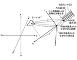
距離dは、内視鏡30の先端からターゲットTまでの距離である。内視鏡30の先端の位置は、内視鏡30の磁気センサ33を用いて検出することができる。また、ターゲットTの位置はステップST1で求められている。したがって、内視鏡30の先端の位置と、ターゲットTの位置とが分かっているので、距離dを算出することができる。距離dは、算出手段84によって算出される。
距離δは、内視鏡30から外科用器具34を突出させたと仮想したときの外科用器具34の仮想の突出距離を表している。この場合、ベクトルUおよびVは、距離δだけベクトルNの方向に平行移動する。距離δは、術者によって設定される。
距離Δは、外科用器具34の仮想の先端位置からターゲットTまでの距離gを、ベクトルNに投影したときの投影成分の長さを表している。距離gは、外科用器具34の仮想の先端位置とターゲットTの位置から算出することができる。したがって、距離gをベクトルNに投影することにより、距離Δを算出することができる。距離Δは、算出手段84によって算出される。
このように、表示部10には、ターゲットTや距離d、δ、Δなども表示される。
術者は、表示部10(図41参照)を見て、ターゲットTの位置を確認し、ターゲットTが内視鏡画像の中心点Cに重なっているか否かを判断する。図41では、ターゲットTは、内視鏡画像の中心点Cからずれている。そこで、術者は、ターゲットTが内視鏡画像の中心点Cに重なるように、内視鏡30の位置および向きを調整する。
術者は、表示部10(図41参照)を見て、ターゲットTの位置を確認し、ターゲットTが内視鏡画像の中心点Cに重なっているか否かを判断する。図41では、ターゲットTは、内視鏡画像の中心点Cからずれている。そこで、術者は、ターゲットTが内視鏡画像の中心点Cに重なるように、内視鏡30の位置および向きを調整する。
図44は、内視鏡30の位置および向きを調整した後の様子を概略的に示す図である。図44では、ベクトルNがターゲットTを横切っている。この場合、ターゲットTを内視鏡画像に投影すると、以下のようになる。
図45は、ターゲットTを内視鏡画像に投影するときの説明図である。
図45(a)は、ターゲットTを内視鏡画像に投影するときの様子を示す図、図45(b)は図45(a)をベクトルNの方向から見たときの図である。
ベクトルNがターゲットTを横切る場合、ターゲットNは内視鏡画像の中心に投影される。したがって、表示部10に表示される内視鏡画像を見ると、図46に示すように、内視鏡画像の中心点CにターゲットTが表示されている。術者は、ターゲットTが内視鏡画像の中心点Cに重なっていることを確認したら、外科用器具34の仮想の突出距離δを設定する(図47参照)。
図45(a)は、ターゲットTを内視鏡画像に投影するときの様子を示す図、図45(b)は図45(a)をベクトルNの方向から見たときの図である。
ベクトルNがターゲットTを横切る場合、ターゲットNは内視鏡画像の中心に投影される。したがって、表示部10に表示される内視鏡画像を見ると、図46に示すように、内視鏡画像の中心点CにターゲットTが表示されている。術者は、ターゲットTが内視鏡画像の中心点Cに重なっていることを確認したら、外科用器具34の仮想の突出距離δを設定する(図47参照)。
図47は、外科用器具34の仮想の突出距離δをδ=δ1に設定したときの様子を示す図である。
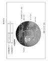
突出距離δ=δ1が設定されると、算出手段84は、距離Δなどを計算する。また、MR装置は、面UVのMR画像を取得するためのスキャンを実行する。このスキャンにより取得された面UVのMR画像は、内視鏡画像とともに表示部10に表示される。図48に、表示部10に表示される画像の一例を示す。
突出距離δ=δ1が設定されると、算出手段84は、距離Δなどを計算する。また、MR装置は、面UVのMR画像を取得するためのスキャンを実行する。このスキャンにより取得された面UVのMR画像は、内視鏡画像とともに表示部10に表示される。図48に、表示部10に表示される画像の一例を示す。
δ=δ1の場合、外科用器具34の仮想の先端位置は、ターゲットTには到達していない(図47参照)。この場合、面UVはターゲットTを横切らないので、術者は、面UVのMR画像を見ても、面UVのMR画像の中に、ターゲットTを確認することができない。したがって、術者は、δ=δ1の位置は、ターゲットTの位置から外れていることが分かる。そこで、術者はδを別の値に設定する(図49参照)。
図49は、術者がδを別の値に設定したときの様子を示す図である。
図49では、δ=dに設定された例が示されている。この場合、外科用器具34の仮想の先端位置はターゲットTに到達している。MR装置は、面UVのMR画像を取得するためのスキャンを実行する。この場合、表示部10には、図50に示すような画像が表示される。
図49では、δ=dに設定された例が示されている。この場合、外科用器具34の仮想の先端位置はターゲットTに到達している。MR装置は、面UVのMR画像を取得するためのスキャンを実行する。この場合、表示部10には、図50に示すような画像が表示される。
δ=dの場合、外科用器具34の仮想の先端位置はターゲットTに到達しているので(図49参照)、術者は、面UVのMR画像の中に、ターゲットTを確認することができる。
以下同様に、術者は、δの値を変更し、δの値ごとに得られる面UVのMR画像を確認する。このように、δの値ごとに得られる面UVのMR画像を確認することにより、術者は、ターゲットTの位置、大きさ、形状などの情報を確認することができる。術者はターゲットTの位置、大きさ、形状などを確認したら、内視鏡30の先端から外科用器具34を実際に突出させ、ターゲットTに外科的処置を施し、治療を行う。
第4の形態では、術者は、表示部10を見ることにより、内視鏡画像とターゲットTとの位置関係を確認することができる。また、距離Δを算出することによって、外科用器具34の仮想の先端位置からターゲットTまでの距離を知ることもできるので、術者がδの値を設定するときの参考にすることができる。
尚、第4の形態では、面UVのMR画像を表示しているが、更に、面NUおよび面NV(図4参照)のMR画像を表示させてもよい。図51に、面UVのMR画像、面NUのMR画像、および面NVのMR画像を表示させたときの一例を示す。これらのMR画像を表示することにより、術者は、互いに直交する3面のMR画像を確認することができるので、内視鏡30の先端の位置や向きの調整をスムーズに行うことができる。
また、第1~第4の形態では、磁気共鳴装置について説明されている。しかし、本発明は、内視鏡画像を表示する表示装置を有する医用装置であれば、磁気共鳴装置とは別の医用装置(例えば、CT装置)に適用することができる。
また、第1~第4の形態では、動物11の内視鏡画像を取得する例について説明されている。しかし、本発明は、内視鏡で観察される対象は、動物に限定されることはなく、人体や、生物以外の物体(例えば、配管の内部や、建物の内部)を、内視鏡で観察される対象とすることができる。
2 マグネット
3 テーブル
3a クレードル
4 受信コイル
5 送信器
6 勾配磁場電源
7 受信器
8 制御部
9 操作部
10 表示部
11 動物
12、13 術者
21 ボア
81 投影手段
82 選択手段
83 表示制御手段
3 テーブル
3a クレードル
4 受信コイル
5 送信器
6 勾配磁場電源
7 受信器
8 制御部
9 操作部
10 表示部
11 動物
12、13 術者
21 ボア
81 投影手段
82 選択手段
83 表示制御手段
Claims (16)
- 対象を観察する内視鏡により得られた内視鏡画像を表示する表示装置であって、
前記対象に対して設定された座標軸を、前記内視鏡画像に投影する投影手段と、
前記内視鏡画像と、前記内視鏡画像に投影された前記座標軸とを表示する表示部と、を有する表示装置。 - 前記対象に対して複数の座標軸が設定されており、
前記投影手段は、
前記複数の座標軸を前記内視鏡画像に投影し、
前記表示部は、
前記内視鏡画像と、前記内視鏡画像に投影された前記複数の座標軸とを表示する、請求項1に記載の表示装置。 - 前記複数の座標軸の中から前記表示部に表示する座標軸を選択する選択手段を有し、
前記表示部は、
前記選択手段により選択された座標軸を表示する、請求項2に記載の表示装置。 - 前記選択手段は、
前記複数の座標軸の各々と前記内視鏡の視野方向との成す角度に基づいて、前記座標軸を選択する、請求項3に記載の表示装置。 - 前記内視鏡の先端の角度を算出する第1の算出手段を有する、請求項1~4のうちのいずれか一項に記載の表示装置。
- 前記第1の算出手段は、
前記内視鏡の先端の仰角を算出する、請求項5に記載の表示装置。 - 前記第1の算出手段は、
前記内視鏡の先端の方位角を算出する、請求項5又は6に記載の表示装置。 - 前記内視鏡の先端には、前記対象のターゲットに対して外科的処置を施すための外科用器具が備えられており、
前記外科用器具は、前記内視鏡の視野方向に突出させることができる、請求項1~7のうちのいずれか一項に記載の表示装置。 - 前記表示部は、
前記対象のターゲットを表示する、請求項8に記載の表示装置。 - 前記内視鏡の先端位置から前記対象のターゲットまでの距離を算出する第2の算出手段を有する、請求項8又は9に記載の表示装置。
- 前記表示部は、
前記内視鏡の先端位置から前記対象のターゲットまでの距離を表示する、請求項10に記載の表示装置。 - 前記内視鏡は、前記外科用器具を前記内視鏡の先端から突出させたと仮想したときの前記外科用器具の仮想の突出距離を設定することができるように構成されている、請求項8~11のうちのいずれか一項に記載の表示装置。
- 前記表示部は前記突出距離を表示する、請求項12に記載の表示装置。
- 請求項1~13のうちのいずれか一項に記載の医用装置。
- 対象を観察する内視鏡により得られた内視鏡画像を表示する表示方法であって、
前記対象に対して設定された座標軸を、前記内視鏡画像に投影する投影ステップと、
前記内視鏡画像と、前記内視鏡画像に投影された前記座標軸とを表示する表示ステップと、を有する表示方法。 - 対象を観察する内視鏡により得られた内視鏡画像を表示する表示部を備えた表示装置のプログラムであって、
前記対象に対して設定された座標軸を、前記内視鏡画像に投影する投影処理と、
前記表示部に、前記内視鏡画像と、前記内視鏡画像に投影された前記座標軸とを表示させる表示制御処理と、
を計算機に実行させるためのプログラム。
Priority Applications (2)
| Application Number | Priority Date | Filing Date | Title |
|---|---|---|---|
| CN201380055175.6A CN104768442A (zh) | 2012-10-22 | 2013-10-15 | 显示装置、医用装置、显示方法及程序 |
| US14/437,728 US9826889B2 (en) | 2012-10-22 | 2013-10-15 | Display device, medical device, display method and program |
Applications Claiming Priority (2)
| Application Number | Priority Date | Filing Date | Title |
|---|---|---|---|
| JP2012-233156 | 2012-10-22 | ||
| JP2012233156A JP6221166B2 (ja) | 2012-10-22 | 2012-10-22 | 表示装置、医用装置、およびプログラム |
Publications (1)
| Publication Number | Publication Date |
|---|---|
| WO2014065154A1 true WO2014065154A1 (ja) | 2014-05-01 |
Family
ID=50544534
Family Applications (1)
| Application Number | Title | Priority Date | Filing Date |
|---|---|---|---|
| PCT/JP2013/077928 Ceased WO2014065154A1 (ja) | 2012-10-22 | 2013-10-15 | 表示装置、医用装置、表示方法、およびプログラム |
Country Status (4)
| Country | Link |
|---|---|
| US (1) | US9826889B2 (ja) |
| JP (1) | JP6221166B2 (ja) |
| CN (1) | CN104768442A (ja) |
| WO (1) | WO2014065154A1 (ja) |
Families Citing this family (2)
| Publication number | Priority date | Publication date | Assignee | Title |
|---|---|---|---|---|
| JP6356623B2 (ja) * | 2015-03-18 | 2018-07-11 | 富士フイルム株式会社 | 画像処理装置、方法、及びプログラム |
| CN110831536B (zh) | 2017-12-06 | 2021-09-07 | 奥瑞斯健康公司 | 用于针对非命令器械滚转进行校正的系统和方法 |
Citations (6)
| Publication number | Priority date | Publication date | Assignee | Title |
|---|---|---|---|---|
| JPS62209481A (ja) * | 1986-02-17 | 1987-09-14 | 三菱電機株式会社 | 三次元カ−ソル表示装置 |
| JPH01269986A (ja) * | 1988-04-21 | 1989-10-27 | Nec Corp | 座標指示方式 |
| JP2001104333A (ja) * | 1999-10-07 | 2001-04-17 | Hitachi Ltd | 手術支援装置 |
| JP2003123097A (ja) * | 2002-09-09 | 2003-04-25 | Hitachi Medical Corp | 表示方法及び表示装置 |
| JP2006116289A (ja) * | 2004-09-27 | 2006-05-11 | Olympus Corp | 湾曲制御装置 |
| JP2007007041A (ja) * | 2005-06-29 | 2007-01-18 | Hitachi Medical Corp | 手術支援装置 |
Family Cites Families (10)
| Publication number | Priority date | Publication date | Assignee | Title |
|---|---|---|---|---|
| US6221007B1 (en) * | 1996-05-03 | 2001-04-24 | Philip S. Green | System and method for endoscopic imaging and endosurgery |
| CN100525699C (zh) | 2004-09-27 | 2009-08-12 | 奥林巴斯株式会社 | 弯曲控制装置 |
| WO2006070669A1 (ja) | 2004-12-27 | 2006-07-06 | Olympus Corporation | 医療画像処理装置及び医療画像処理方法 |
| JP5226538B2 (ja) * | 2007-02-14 | 2013-07-03 | オリンパスメディカルシステムズ株式会社 | 操作装置、モニタ装置、およびカプセル誘導システム |
| JP5085662B2 (ja) * | 2007-11-29 | 2012-11-28 | オリンパスメディカルシステムズ株式会社 | 内視鏡システム |
| JP5410021B2 (ja) | 2008-01-22 | 2014-02-05 | 株式会社日立メディコ | 医用画像診断装置 |
| US8864652B2 (en) | 2008-06-27 | 2014-10-21 | Intuitive Surgical Operations, Inc. | Medical robotic system providing computer generated auxiliary views of a camera instrument for controlling the positioning and orienting of its tip |
| EP2351509A4 (en) | 2008-10-28 | 2018-01-17 | Olympus Corporation | Medical device |
| WO2011040104A1 (ja) * | 2009-09-30 | 2011-04-07 | オリンパスメディカルシステムズ株式会社 | 内視鏡装置及び湾曲駆動制御方法 |
| JP5551957B2 (ja) * | 2010-03-31 | 2014-07-16 | 富士フイルム株式会社 | 投影画像生成装置およびその作動方法、並びに投影画像生成プログラム |
-
2012
- 2012-10-22 JP JP2012233156A patent/JP6221166B2/ja not_active Expired - Fee Related
-
2013
- 2013-10-15 US US14/437,728 patent/US9826889B2/en not_active Expired - Fee Related
- 2013-10-15 WO PCT/JP2013/077928 patent/WO2014065154A1/ja not_active Ceased
- 2013-10-15 CN CN201380055175.6A patent/CN104768442A/zh active Pending
Patent Citations (6)
| Publication number | Priority date | Publication date | Assignee | Title |
|---|---|---|---|---|
| JPS62209481A (ja) * | 1986-02-17 | 1987-09-14 | 三菱電機株式会社 | 三次元カ−ソル表示装置 |
| JPH01269986A (ja) * | 1988-04-21 | 1989-10-27 | Nec Corp | 座標指示方式 |
| JP2001104333A (ja) * | 1999-10-07 | 2001-04-17 | Hitachi Ltd | 手術支援装置 |
| JP2003123097A (ja) * | 2002-09-09 | 2003-04-25 | Hitachi Medical Corp | 表示方法及び表示装置 |
| JP2006116289A (ja) * | 2004-09-27 | 2006-05-11 | Olympus Corp | 湾曲制御装置 |
| JP2007007041A (ja) * | 2005-06-29 | 2007-01-18 | Hitachi Medical Corp | 手術支援装置 |
Also Published As
| Publication number | Publication date |
|---|---|
| US9826889B2 (en) | 2017-11-28 |
| US20150272427A1 (en) | 2015-10-01 |
| CN104768442A (zh) | 2015-07-08 |
| JP6221166B2 (ja) | 2017-11-01 |
| JP2014083156A (ja) | 2014-05-12 |
Similar Documents
| Publication | Publication Date | Title |
|---|---|---|
| US11737850B2 (en) | Methods and systems for display of patient data in computer-assisted surgery | |
| US11950858B2 (en) | Systems for performing computer assisted surgery | |
| EP2769689B1 (en) | Computer-implemented technique for calculating a position of a surgical device | |
| US10463447B2 (en) | System and method for detecting and adjusting reference marker errors in surgical navigation systems | |
| EP4090254A1 (en) | Systems and methods for autonomous suturing | |
| US20220192756A1 (en) | Attachment apparatus to secure a medical alignment device to align a tool | |
| JP2017000772A (ja) | ロボット支援手術のための装置及び方法 | |
| KR20160086629A (ko) | 영상유도 수술에서 수술부위와 수술도구 위치정합 방법 및 장치 | |
| WO2015135059A1 (en) | System and method detecting and adjusting for reference marker errors in surgical navigation systems | |
| CN106456135A (zh) | 医疗系统 | |
| US12279834B2 (en) | Detection of unintentional movement of a reference marker and automatic re-registration | |
| JP2018520790A (ja) | 医療支援デバイス | |
| EP2574282A1 (en) | Ultrasound diagnostic apparatus and method thereof | |
| JP6221166B2 (ja) | 表示装置、医用装置、およびプログラム | |
| US12394086B2 (en) | Accuracy check and automatic calibration of tracked instruments | |
| CN118806323A (zh) | 超声波影像系统 | |
| JP4458492B2 (ja) | 手術支援ロボットの動作制御システム及び位置検出装置 | |
| CN115802966A (zh) | 用于将介入器械引导至内部目标的系统 | |
| US12419719B2 (en) | Camera apparatus for coordinated operation with surgical tools | |
| KR20150053202A (ko) | 수술용 항법 시스템의 교정 방법 | |
| JP2009201701A (ja) | 術具誘導手術支援装置 | |
| JP2023507434A (ja) | プローブの遠位端からの方向による医用画像上のカーソル位置の選択 | |
| HK40055430A (en) | System and method for medical device placement in bone | |
| HK40055431A (en) | System and method for medical device placement in bone |
Legal Events
| Date | Code | Title | Description |
|---|---|---|---|
| 121 | Ep: the epo has been informed by wipo that ep was designated in this application |
Ref document number: 13848716 Country of ref document: EP Kind code of ref document: A1 |
|
| NENP | Non-entry into the national phase |
Ref country code: DE |
|
| WWE | Wipo information: entry into national phase |
Ref document number: 14437728 Country of ref document: US |
|
| 122 | Ep: pct application non-entry in european phase |
Ref document number: 13848716 Country of ref document: EP Kind code of ref document: A1 |