WO2014065147A1 - 船体制御方法および船体制御装置 - Google Patents
船体制御方法および船体制御装置 Download PDFInfo
- Publication number
- WO2014065147A1 WO2014065147A1 PCT/JP2013/077891 JP2013077891W WO2014065147A1 WO 2014065147 A1 WO2014065147 A1 WO 2014065147A1 JP 2013077891 W JP2013077891 W JP 2013077891W WO 2014065147 A1 WO2014065147 A1 WO 2014065147A1
- Authority
- WO
- WIPO (PCT)
- Prior art keywords
- ship
- disturbance
- fixed point
- point position
- hull control
- Prior art date
- Legal status (The legal status is an assumption and is not a legal conclusion. Google has not performed a legal analysis and makes no representation as to the accuracy of the status listed.)
- Ceased
Links
Images











Classifications
-
- B—PERFORMING OPERATIONS; TRANSPORTING
- B63—SHIPS OR OTHER WATERBORNE VESSELS; RELATED EQUIPMENT
- B63H—MARINE PROPULSION OR STEERING
- B63H21/00—Use of propulsion power plant or units on vessels
- B63H21/21—Control means for engine or transmission, specially adapted for use on marine vessels
-
- B—PERFORMING OPERATIONS; TRANSPORTING
- B63—SHIPS OR OTHER WATERBORNE VESSELS; RELATED EQUIPMENT
- B63H—MARINE PROPULSION OR STEERING
- B63H25/00—Steering; Slowing-down otherwise than by use of propulsive elements; Dynamic anchoring, i.e. positioning vessels by means of main or auxiliary propulsive elements
- B63H25/02—Initiating means for steering, for slowing down, otherwise than by use of propulsive elements, or for dynamic anchoring
- B63H25/04—Initiating means for steering, for slowing down, otherwise than by use of propulsive elements, or for dynamic anchoring automatic, e.g. reacting to compass
-
- G—PHYSICS
- G05—CONTROLLING; REGULATING
- G05D—SYSTEMS FOR CONTROLLING OR REGULATING NON-ELECTRIC VARIABLES
- G05D1/00—Control of position, course, altitude or attitude of land, water, air or space vehicles, e.g. using automatic pilots
- G05D1/02—Control of position or course in two dimensions
- G05D1/0206—Control of position or course in two dimensions specially adapted to water vehicles
Definitions
- the present invention relates to a hull control method for moving a ship to a fixed point and holding the ship at a fixed point.
- the hull may be subjected to disturbances caused by wind or tides, and may be washed away from the fixed point position or may not be able to navigate efficiently to the fixed point position.
- the ship shown in Patent Document 1 includes a side thruster.
- the side thruster is a mechanism for moving the hull in the lateral direction, that is, in the starboard and port directions.
- some conventional ships include a propeller that can be rotated in the horizontal direction in order to realize such lateral movement.
- An object of the present invention is to provide a hull control method capable of controlling a hull equivalent to these additional equipments without carrying out large-scale additional equipments such as a side thruster and a propeller capable of turning in a starboard direction. .
- the hull control method includes a step of acquiring a ship position and a step of detecting a disturbance direction which is a disturbance direction that gives an external force to the ship with reference to the ship.
- the hull control method includes a step of calculating a target direction toward a fixed point position from a preset fixed point position and the own ship position, and a step of detecting a target direction at the fixed point position from a disturbance direction.
- the hull control method calculates the navigation azimuth, which is the direction in which the ship navigates, from the target azimuth toward the fixed point position and the target azimuth at the fixed point position, and adjusts the rudder angle according to the navigation azimuth. And a step of performing.
- the ship can sail toward the fixed point position so that the heading direction and the disturbance direction gradually coincide with each other.
- the step of calculating the navigation direction of the hull control method of the present invention calculates the navigation direction by weighted addition of the target direction toward the fixed point position and the target direction at the fixed point position.
- the weighted addition is set so that the weight of the heading at the fixed point position becomes heavier as the ship approaches the fixed point position.
- This method shows a specific calculation example of the navigation direction.
- the hull control method of the present invention includes a step of detecting the magnitude of the disturbance and a step of calculating the target ship speed at the fixed point position from the magnitude of the disturbance.
- the hull control method includes a step of calculating a navigation ship speed, which is a speed at which the ship navigates at that time, from a target ship speed that directs the ship to a fixed position and a target ship speed at the fixed position. Adjusting the thrust according to the ship speed.
- the optimum navigation ship speed is determined from the target ship speed for causing the ship to reach the fixed point position and the target ship speed at the fixed point position.
- the step of calculating the navigation ship speed of the hull control method of the present invention calculates the navigation ship speed by weighted addition of the target ship speed and the ship speed at the fixed point position.
- the weighted addition is set so that the weight of the ship speed at the fixed point position becomes heavier as the ship approaches the fixed point position.
- This method shows a specific calculation example of navigation ship speed.
- the hull control method of the present invention includes a step of acquiring the ship position, and a step of detecting a disturbance direction that is a direction of a disturbance that gives an external force to the ship with reference to the ship.
- the hull control method is based on the process of setting a disturbance orthogonal line orthogonal to the disturbance direction and passing through a fixed point position, and by adjusting the thrust and steering angle, the relationship between the disturbance orthogonal line and the ship position is approximated to the disturbance direction. And advancing or reversing the ship along a parallel direction.
- the ship can be kept near the fixed point position in a state where the heading and the disturbance direction are substantially matched.
- the hull control method of the present invention includes a step of detecting the heading of the own ship.
- the process of advancing or reversing the ship in the hull control method involves moving the ship backward when the ship's position is on the disturbance side with respect to the disturbance orthogonal line when the bow direction of the ship and the disturbance direction are substantially the same.
- the ship is advanced when the ship position is on the opposite side of the disturbance with respect to the disturbance orthogonal line.
- This method shows a specific method for switching forward and backward.
- the hull control method of the present invention includes a step of detecting a distance that the ship is farthest from a fixed point position on a disturbance opposing line parallel to the disturbance direction, and a thrust adjustment in which the distance that is the farthest is determined by the magnitude of the disturbance Reducing the thrust of the ship when longer than the threshold distance for use.
- the hull control method of the present invention includes a step of detecting a distance that the ship is farthest from a fixed point position on a disturbance opposing line parallel to the disturbance direction, and a thrust adjustment in which the distance that is the farthest is determined by the magnitude of the disturbance Increasing the thrust of the ship when it is shorter than the threshold distance for use.
- the step of detecting the distance at which the ship is farthest from the fixed point position on the disturbance opposing line parallel to the disturbance direction, and the timing for turning on the thrust based on the distance at which the ship is furthest away are turned off. Adjust one of the timings.
- the range of movement of the ship relative to the fixed point position can be further narrowed.
- the hull control method of the present invention executes a step of moving the own ship forward or backward when the difference between the bow direction and the disturbance direction is equal to or less than a threshold value.
- the forward / reverse control for keeping the above-mentioned ship near the fixed point position is performed only when the difference between the heading and the disturbance direction is small. As a result, the ship can be more securely retained near the fixed point position.
- the hull control method of the present invention executes a step of changing the heading when the difference between the heading and the disturbance heading is larger than the threshold value.
- the step of changing the heading of the hull control method of the present invention includes the step of adjusting the rudder angle while moving the boat backward to bring the heading and disturbance directions closer, and the step of adjusting the rudder angle while moving the boat forward. And a step of bringing the bow direction and the disturbance direction close to each other.
- This method shows a specific method for changing the heading. By using this method, the heading can be easily changed using disturbance.
- the hull control method of the present invention executes a step of moving the ship forward or backward when the own ship position is within a predetermined distance range centered on the fixed point position.
- This hull control method includes the following steps when the ship position deviates from a predetermined range.
- the hull control method includes a step of calculating a target direction from the fixed point position and the own ship position toward the fixed point position, a step of detecting the target direction at the fixed point position from the disturbance direction, and a target direction and fixed point toward the fixed point position.
- a step of calculating a navigation direction which is a direction in which the ship navigates at that time from the target direction at the position.
- This hull control method includes a step of detecting the magnitude of a disturbance, a step of calculating a ship speed at a fixed point position from the magnitude of the disturbance, a target ship speed that is a ship speed for directing the ship to a fixed point position, and a fixed point.
- a step of calculating a navigation ship speed which is a speed at which the ship navigates at that time, from the target ship speed at the position;
- This hull control method includes the steps of adjusting the rudder angle according to the navigation direction and adjusting the thrust according to the navigation ship speed.
- the thrust and the steering angle may be adjusted at different timings.
- This method does not adjust thrust and rudder angle at the same time, so the target ship movement can be realized more stably.
- the thrust and the rudder angle may be set to discrete values.
- This method facilitates thrust control and rudder angle control while enabling movement substantially equivalent to analog thrust control and rudder angle control.
- the hull control method of the present invention includes a step of performing notification according to the distance between the ship position and the fixed point position.
- the notification is set differently depending on the distance.
- This method allows the user to intuitively understand the distance between the ship and the fixed point.
- the hull control method of the present invention includes a step of accepting an operation input according to a fish type, a step of selecting an operation mode associated with the fish type, and a step of controlling the ship based on the selected operation mode And having.
- the user can intuitively select how to move the ship.
- FIG. 3 is a block diagram showing the main structures of the ship which concerns on the 1st Embodiment of this invention.
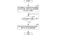
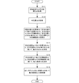
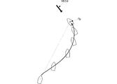
- 3 is a flowchart of hull control according to the first embodiment of the present invention. It is a flowchart of the navigation control to the fixed point position Pp. It is a figure which shows the relationship of each parameter used for navigation control to the fixed point position Pp. It is a figure which shows the example of a wake when the navigation control of this invention is performed. It is a figure which shows the example of a setting of weighting.
- FIG. 3 is a block diagram showing a configuration of a direction ship speed setting unit 41 of the hull control unit 24. It is a flowchart of fixed point holding
- FIG. 1 is a block diagram showing the main configuration of a ship according to the first embodiment of the present invention.
- the ship 10 includes a hull control device 20, a power source 30, a propeller 31, and a rudder 40.
- the hull control device 20 includes an antenna 21, a positioning unit 22, a sensor 23, a hull control unit 24, and an operation unit 25.
- a set of the power source 30 and the propeller 31 corresponds to a “propulsion generation unit”.
- the antenna 21 receives the GPS positioning signal and outputs it to the positioning unit 22.
- the positioning unit 22A performs a positioning calculation using the GPS positioning signal, and calculates the position (own ship position) Ps of the ship 10. This positioning calculation is executed at every positioning timing set in advance.
- the positioning unit 22 outputs the calculated own ship position Ps to the hull control unit 24.
- the sensor 23 includes, for example, a heading sensor that detects the heading ADb, a wind direction sensor, a wind speed sensor, a tide meter, and the like.
- the sensor 23 calculates a disturbance vector VECd from the wind direction, wind speed, tidal direction, and tidal speed.
- the disturbance vector VECd is defined by an addition vector of the wind vector VECw and the tidal vector VECt.
- the vector direction of the wind vector VECw is determined by the wind direction, and the magnitude of the wind vector VECw is determined by the wind speed.
- the vector direction of the tidal vector VECt is determined by the tidal direction, and the magnitude of the tidal vector VECt is determined by the tidal velocity.
- Sensor 23 outputs the detected bow direction ADb and disturbance vector VECd to hull control unit 24.
- the sensor 23 may output the wind vector VECw and the tidal current vector VECt to the hull control unit 24.
- the sensor 23 may output the wind vector VECw and the tidal vector VECt to the hull control unit 24, and the hull control unit 24 may calculate the disturbance vector VECd from the wind vector VECw and the tidal vector VECt.
- the hull control unit 24 stores a fixed point position Pp set by the user via the operation unit 25 in advance. Although a specific control method will be described later, the hull control unit 24 executes navigation control to the fixed point position or fixed point holding control based on the fixed point position Pp and the own ship position Ps. Schematically, when the distance DIS between the fixed point position Pp and the ship position Ps is larger than a predetermined value, navigation control to the fixed point position is performed, and when the distance DIS is equal to or smaller than the predetermined value, the fixed point holding control is performed. I do.
- the hull control unit 24 controls the driving of the power source 30 based on the thrust determined by the navigation control to the fixed point position or the fixed point holding control.
- the hull control unit 24 performs the rudder angle control of the rudder 40 based on the rudder angle determined by the navigation control to the fixed point position or the fixed point holding control.
- the operation unit 25 is a so-called user interface device, and outputs an operation input by the user to the hull control unit 24.
- the power source 30 is composed of a diesel engine or a motor. Further, a hybrid power mechanism that includes these diesel engines and motors and that can be used depending on the situation may be used.
- the power source 30 is driven and controlled by the hull control unit 24.
- the power source 30 gives the generated power to the propeller 31.
- the rudder 40 is provided at the stern of the ship 10.
- the rudder 40 is steered by the hull control unit 24.
- the ship 10 navigates to a fixed point or moves forward or backward to maintain a fixed point depending on the propulsive force of the propeller 31 and the rudder angle of the rudder 40.
- the backward movement includes a case where the propeller 31 is stopped and moved backward due to disturbance.
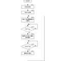
- FIG. 2 is a flowchart of hull control according to the embodiment of the present invention.
- FIG. 2 shows a case where the distance DIS between the ship position Ps and the fixed point position Pp is separated from a predetermined value.
- the distance DIS is equal to or smaller than the predetermined value, the movement control to the fixed point position is not performed and the fixed point holding control is performed.
- the hull control unit 24 performs thrust control and steering angle control so that the ship 10 sails toward the fixed point position Pp based on the own ship position Ps, the fixed point position Pp, the disturbance vector VECd, and the heading ADb. .
- the hull control unit 24 detects, as the disturbance direction ADd, a direction opposite to the direction in which the disturbance vector VECd faces and based on the fixed point position Pp.
- the hull control unit 24 navigates the ship 10 while performing thrust control and steering angle control so that the bow direction ADb and the disturbance direction ADd substantially coincide with each other at the fixed point position Pp (S101).
- This navigation control is continuously executed until the own ship position Ps and the fixed point position Pp substantially coincide (S102: No ⁇ S101).
- the hull control unit 24 When it is detected that the own ship position Ps and the fixed point position Pp substantially coincide with each other (S102: Yes), the hull control unit 24 maintains the state where the bow direction ADb and the disturbance direction ADd substantially coincide with each other, and the fixed point position Ps and Thrust control and rudder angle control are performed so that the ship 10 stays in the region near the fixed point position Ps, and fixed point holding control is performed (S103).
- FIG. 3 is a flowchart of the navigation control to the fixed point position Pp.
- the navigation control shown in FIG. 3 is continuously performed at predetermined time intervals until the fixed point position Pp is reached via the navigation to the fixed point position Pp.
- FIG. 4 is a diagram showing the relationship of each parameter used for navigation control to the fixed point position Pp.
- FIG. 5 is a diagram showing a wake example when the navigation control of the present invention is performed.
- FIG. 6 is a diagram illustrating a setting example of weighting. Unless otherwise specified, the speeds shown below are absolute speeds (ground speeds), the coordinates are the absolute coordinates of the earth surface, and the direction is the north reference direction.
- the own ship position Ps and the fixed point position Pp are acquired (S111). Acquisition of the fixed point position Pp is executed by the user designating the coordinates of the fixed point position Pp through the operation unit 25.
- the fixed point position Pp may be acquired only at the start timing of navigation to the fixed point position Pp.
- the own ship position Ps is acquired from the positioning result by the positioning unit 22 described above. When the own ship position Ps and the fixed point position Pp are acquired, the distance between the two points, that is, the distance DIS from the own ship position Ps to the fixed point position Pp at this time is calculated.
- each parameter of the disturbance element is acquired (S112).
- the disturbance is expressed by a combination of wind and current and can be expressed by a velocity vector.
- the wind vector VECw is acquired from the wind direction and the wind speed measured by the sensor 23.
- the tidal vector VECt is acquired from the tidal direction and tidal velocity measured by the sensor 23.
- the disturbance vector VECd is obtained as a combined vector of the wind vector VECw and the tidal vector VECt. Therefore, the disturbance vector VECd is calculated by adding the wind vector VECw, the power flow vector VECt, and the vector.
- the calculated disturbance vector VECd is that of the ship position Ps.
- the disturbance vector VECd is regarded as the disturbance vector VECd of the fixed point position Pp. Even if such a method is used, if the ship 10 actually approaches the fixed point position Pp, the own ship position Ps and the fixed point position Pp substantially coincide with each other. Therefore, the disturbance vector VECd of the own ship position Ps is set to the fixed point position Pp. Even with the disturbance vector VECd, navigation control with sufficient accuracy is possible. Further, even if the ship position Ps and the fixed point position Pp are separated from each other, the disturbance vector VECd does not change greatly. Further, as the ship sails toward the fixed point position Pp, the disturbance vector VECd of the ship position Ps and the fixed point are not changed. Since there is almost no difference from the disturbance vector VECd at the position Pp, navigation control with sufficient accuracy is possible.
- the target orientation ⁇ p toward the fixed point position is calculated by geometric calculation from the coordinates of the ship position Ps and the coordinates of the fixed point position Pp. Further, when the user operates the operation unit 25, the target ship speed Vp toward the fixed point position Pp is acquired.
- the target bearing ⁇ d at the fixed point position Pp and the target ship speed (fixed ship speed) Vd are acquired.
- the target azimuth ⁇ d at the fixed point position Pp is set to an azimuth opposite to the azimuth of the disturbance vector VECd.
- the ship speed Vd at the fixed point position Pp is set to the same size as the magnitude of the disturbance vector VECd, for example. In this case, the ground speed at the fixed point position Pp is set to be zero.
- the navigation direction ⁇ o at that time is determined using the target direction ⁇ p toward the fixed point position and the target direction ⁇ d at the fixed point position (S114).
- the navigation direction ⁇ o is calculated using the following weighted addition formula.
- ⁇ 1 ⁇ exp ⁇ (DIS / DISo) Therefore, ⁇ is expressed by the following equation.
- the navigation azimuth ⁇ o By calculating the navigation azimuth ⁇ o by such an expression, the navigation azimuth ⁇ o approaches the target azimuth ⁇ p toward the fixed point position as it is far from the fixed point position Pp, and approaches the target azimuth ⁇ d at the fixed point position as it approaches the fixed point position Pp. As it gradually changes. Thereby, the ship 10 can be navigated toward the fixed point position Pp while smoothly changing the navigation direction ⁇ o from the target direction ⁇ p toward the fixed point position to the target direction ⁇ d at the fixed point position.
- the navigation ship speed Vo at that time is determined (S115).
- the navigation ship speed Vo is calculated using the following weighted addition formula.
- Vo ⁇ Vp + ⁇ Vd
- the navigation ship speed Vo approaches the target ship speed Vp toward the fixed point position as it is far from the fixed point position Pp, and the target ship at the fixed point position as it approaches the fixed point position Pp. It gradually changes so as to approach the speed Vd. Thereby, the ship 10 can be navigated toward the fixed point position Pp while smoothly changing the navigation ship speed Vo from the target ship speed Vp toward the fixed point position to the target ship speed Vd at the fixed point position.
- the thrust applied to the power source 30 is determined using the calculated navigation ship speed Vo.
- the rudder angle given to the rudder 40 is determined using the calculated navigation direction ⁇ o (S116).
- the heading gradually opposes the disturbance direction while being flown by the disturbance from the navigation start position to the fixed point position Pp toward the fixed point position Pp (
- the ship 10 can be navigated to the fixed point position Pp.
- the bow direction can be opposed to the disturbance direction.
- the bow direction and the disturbance direction are made to face each other (the angle formed by the direction of the disturbance vector and the bow direction is 180 °).
- the start of the following fixed point holding control can be facilitated.
- FIG. 7 is a block diagram showing the configuration of the bearing speed setting unit 41 of the hull control unit 24.
- the bearing ship speed setting unit 41 includes a navigation condition determination unit 42 and a weighting processing unit 43.
- the navigation condition determination unit 42 includes a fixed point direction vector calculation unit 421 and a fixed point position vector calculation unit 422.
- the fixed point direction vector calculation unit 421 calculates a target orientation ⁇ p that goes from the fixed point position Pp and the own ship position Ps toward the fixed point position. Further, the fixed point direction vector calculation unit 421 determines a target ship speed Vp toward the fixed point position based on the operation input.
- the fixed point position vector calculation unit 422 calculates the fixed point ship speed Vd from the disturbance vector VECd.
- the fixed point position vector calculation unit 422 determines the fixed point ship speed Vd based on the operation input.
- the weighting processing unit 43 includes a weighting coefficient setting unit 433, multipliers 4341, 4342, 4343, 4344, and adders 4351, 4352.
- the weighting coefficient setting unit 433 determines the weighting coefficients ⁇ and ⁇ based on the distance DIS.
- the multiplier 4341 is given a target orientation ⁇ p and a weighting coefficient ⁇ toward the fixed point position. At this time, the target direction ⁇ p toward the fixed point position is given after being converted into a unit vector. Multiplier 4341 multiplies target orientation ⁇ p toward the fixed point position by weighting coefficient ⁇ and outputs multiplication result ⁇ p to adder 4351.
- the multiplier 4342 is given a target orientation ⁇ d and a weighting coefficient ⁇ at a fixed point position. At this time, the target orientation ⁇ d at the fixed point position is given after being converted into a unit vector. Multiplier 4342 multiplies target orientation ⁇ d at the fixed point position by weighting coefficient ⁇ and outputs multiplication result ⁇ d to adder 4351.
- the adder 4351 adds the multiplication result ⁇ p and the multiplication result ⁇ d to calculate the navigation direction ⁇ 0 and outputs it.
- the multiplier 4343 is given a target ship speed Vp toward the fixed point position and a weighting coefficient ⁇ .
- the multiplier 4343 multiplies the target ship speed Vp toward the fixed point position by the weighting coefficient ⁇ and outputs the multiplication result ⁇ Vp to the adder 4352.
- the multiplier 4344 is given a target ship speed Vd at a fixed point position and a weighting coefficient ⁇ .
- the multiplier 4344 multiplies the target ship speed Vd at the fixed point position by the weighting coefficient ⁇ and outputs the multiplication result ⁇ Vd to the adder 4352.
- the adder 4352 adds the multiplication result ⁇ Vp and the multiplication result ⁇ Vd to calculate and output the navigation ship speed Vo.
- the ship 10 can be navigated to the fixed point position Pp while gradually changing so that the bow direction is opposed (parallel) to the disturbance direction.
- FIG. 8 is a flowchart of the fixed point holding control.
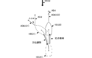
- FIG. 9 is a diagram showing the concept of forward / reverse switching.
- ADb the heading
- ADd the disturbance direction
- the case where the bow is facing the disturbance direction is shown.
- the forward control and reverse control described later are reversed.
- the arrival of the fixed point position Pp can be detected by the fact that the measured ship position Ps and the fixed point position Pp substantially coincide.
- the own ship position Ps and the fixed point position Pp substantially coincide with each other means that the own ship position Ps is within a predetermined range centered on the fixed point position Pp.
- This range is the vicinity of the fixed point position Pp.
- what is necessary is just to set this radius etc. suitably according to a use aspect.
- the heading ADb is opposed to the direction of the disturbance vector VECd at the fixed point position Pp, in other words, disturbance.
- the ship 10 is subjected to navigation control so as to be parallel to the direction ADd (S215).
- an error angle ⁇ dd between the disturbance direction ADd and the bow direction ADb is calculated (S212).
- the error angle ⁇ dd is obtained, for example, by subtracting the bow direction ADb from the disturbance direction ADd.
- the reverse, that is, the disturbance direction ADd may be subtracted from the bow direction ADb.
- the disturbance direction ADd and the bow direction ADb should be parallel when the fixed point position Pp is reached, and if the disturbance does not change, the error angle ⁇ dd should be constantly zero. It is. However, disturbances change frequently because they are determined by wind and current. Therefore, it is necessary to detect such a change in the error angle ⁇ dd in order to make the bow azimuth ADb parallel to the disturbance azimuth ADd in order to perform fixed point holding control described later.
- a preset error angle threshold Th ⁇ dd is set.
- the error angle threshold Th ⁇ dd is determined by the maximum value of the angle difference (error angle ⁇ dd) between the disturbance direction ADd and the bow direction ADb so that the fixed point can be easily held by forward / reverse control described later. This maximum value can be set in advance by experiments or the like.
- the error angle threshold Th ⁇ dd is set to ⁇ 45 °.
- the disturbance orthogonal line Lver is defined by a straight line orthogonal to the disturbance vector VECd and passing through the fixed point position Pp.
- a region on the disturbance side and the fixed point holding region BorK with respect to the disturbance orthogonal line Lver is defined as a disturbance upper region ZoneU.
- a region on the side opposite to the disturbance and the fixed point holding region BorK with respect to the disturbance orthogonal line Lver is defined as a disturbance lower region ZoneD.
- the fixed point holding backward control is a control for moving the ship 10 backward at the holding boat speed, and is a control for generating thrust and rotating the screw for backward driving or causing the disturbance 10 to flow without generating thrust. It is.
- the bow angle ADb may be adjusted to be parallel to the disturbance direction ADd by appropriately adjusting the rudder angle.
- the fixed point holding forward control is performed (S216).
- the fixed point holding forward control is control for moving the ship 10 forward at the holding boat speed.
- the steering angle ADb may be adjusted as appropriate so that the bow direction ADb is parallel to the disturbance direction ADd.
- the ship 10 when the ship 10 exists in the disturbance upper area ZoneU, the ship 10 is moved so as to reach the disturbance orthogonal line Lver in the fixed point holding area BorK, more preferably the fixed point position Pp itself. It can be moved backward (see ship 10 'in FIG. 9). Further, even when the ship 10 exists in the disturbance under zone ZoneD, the ship 10 can be moved forward so as to reach the disturbance orthogonal line Lver in the fixed point holding region BorK, more preferably the fixed point position Pp itself (FIG. 9), that is, it is possible to keep the ship 10 in a narrow range near the fixed point position Pp. Further, even if the ship 10 is one power and one rudder, the fixed point is determined according to the position of the ship 10. The ship 10 can be automatically moved so as to reach the position Pp.
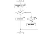
- FIG. 10 is a flowchart showing a thrust control method during forward / backward travel.
- FIG. 11 is a diagram showing the concept of thrust control.
- the horizontal axis represents time
- the vertical axis represents the disturbance opposing line projection distance Ld
- the solid line represents the time change of the wake.
- the disturbance opposing line projection distance Ld is a distance obtained by projecting the distance between the ship position Ps and the fixed point position Pp onto the disturbance opposing line, as shown in the case of the ship 10 'in FIG.
- the disturbance opposing line is a straight line orthogonal to the disturbance orthogonal line Lver (parallel to the disturbance direction ADd) and passing through the fixed point position Pp.
- the disturbance opposing line projection distance Ld can be defined by the same method.
- the thrust is turned off at the time of crossing the disturbance orthogonal line Lver when moving the ship 10 from the disturbance lower zone ZoneD to the disturbance upper zone ZoneU.
- the thrust is turned on when the disturbance orthogonal line Lver when the ship 10 is moved from the zone ZoneU to the zone D under disturbance is crossed.
- the ship 10 When a thrust is generated for the ship 10 existing in the disturbance under zone ZoneD and the ship 10 is advanced, the ship 10 continues to advance even if the thrust is turned off at the time of crossing the disturbance orthogonal line Lver. Then, at the position where the disturbance opposing line direction component of the thrust due to the holding ship speed coincides with the disturbance opposing line direction component of the disturbance, the ship speed of the ship 10 becomes 0, and the vehicle moves backward so as to be flowed by the disturbance.
- the length obtained by projecting the line connecting the position where the ship speed becomes 0 and the fixed point position Pp onto the disturbance opposing line is calculated as the disturbance opposing line maximum projection distance Ldd (S311).
- a preset thrust adjustment threshold Th Ldd is set for the disturbance opposing line maximum projection distance Ldd.
- the thrust adjustment threshold Th Ldd is set according to the thrust of the ship 10, the shape, the magnitude of the disturbance vector VECd, how far the ship 10 is allowed to be away from the fixed point position Pp, and the like.
- thrust reduction control is performed (S313).
- the correction amount ⁇ Vt is, for example, a value that can be appropriately set by the user.
- thrust increase control is performed (S315).
- the ship 10 when the ship 10 moves in the direction of the disturbance from the zone D under the disturbance in the thrust on Vt11 state and turns off the thrust at the time t11 across the disturbance orthogonal line Lver, the ship 10 responds to the thrust applied so far. Advance. Then, the ship 10 temporarily stops at the disturbance opposing line maximum projection distance Ldd (t11).
- the disturbance opposing line maximum projection distance Ldd (t11) is longer than the thrust adjustment threshold Th Ldd , the next thrust Vt12 is reduced by ⁇ Vt from the current thrust Vt11.
- the thrust Vt14 is turned on at this timing.
- the ship 10 is caused to flow into the disturbance underneath Zone D, but again moves back to the disturbance side by the thrust Vt14.
- the thrust Vt15 is turned on at this timing.
- the ship 10 is caused to flow into the disturbance under zone ZoneD, but again moves back to the disturbance side by the thrust Vt15.
- the disturbance opposing line maximum projection distance Ldd (t15) is reached. And pause.
- the disturbance opposing line maximum projection distance Ldd (t14) is longer than the thrust adjustment threshold Th Ldd , the next thrust Vt16 is reduced by ⁇ Vt from the current thrust Vt15.
- the thrust Vt16 is turned on at this timing.
- the ship 10 is caused to flow in the disturbance under-zone ZoneD, but moves back to the disturbance side again by the thrust Vt16.
- the ship 10 moves forward and backward within the range of about twice the thrust adjustment threshold Th Ldd around the disturbance orthogonal line Lver (fixed point position Pp).
- the moving range can be narrowed gradually.
- the ship 10 can repeat forward and backward travel in the range of about twice the thrust adjustment threshold Th Ldd around the disturbance orthogonal line Lver.
- An adaptive process of the thrust adjustment threshold Th Ldd that gradually sets the thrust adjustment threshold Th Ldd is also possible. By performing such an adaptive process, the moving range of the ship 10 is centered on the fixed point position Pp. Further, the range can be made shorter.
- FIG. 12 is a block diagram illustrating a configuration of the fixed point holding control unit.
- the fixed point holding control unit 44 includes an error angle detection unit 441, a forward / reverse determination unit 442, a thrust, and a steering angle determination unit 443.
- the error angle detector 441 calculates an error angle ⁇ dd from the disturbance direction ADd and the bow direction ADb.
- the forward / reverse determination unit 442 sets a disturbance orthogonal line Lver from the disturbance direction ADd and the fixed point position Pp.
- the forward / reverse determination unit 442 determines the fixed point holding area BorK from the fixed point position Pp.
- the forward / reverse determination unit 442 performs any of the navigation control from the fixed point holding area BorK, the disturbance orthogonal line Lver, and the own ship position Ps to the fixed point position described above, the forward control for holding the fixed point, and the reverse control for holding the fixed point. select.
- the forward / reverse determination unit 442 selects the navigation control to the fixed point position if the ship position Ps is outside the fixed point holding area BorK.
- the forward / reverse determination unit 442 selects the backward control for holding the fixed point.
- the forward / reverse determination unit 442 selects the forward control for holding the fixed point if the own ship position Ps is in the fixed point holding region BorK and within the disturbance under zone ZoneD based on the disturbance orthogonal line Lver.
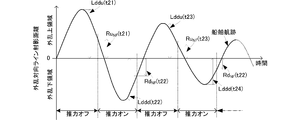
- the thrust / steering angle determination unit 443 determines the thrust and the steering angle from the selected control and the error angle ⁇ dd.
- the fixed point holding control can be performed as described above.
- FIG. 13 is a flowchart of fixed point holding control for adjusting the thrust on / off timing.
- FIG. 14 is a diagram illustrating the concept of fixed point holding control by adjusting the thrust on / off timing.
- the horizontal axis represents time
- the vertical axis represents the disturbance opposing line projection distance Ld
- the solid line represents the time change of the wake.
- the length obtained by projecting the line connecting the position where the boat speed is 0 in the disturbance upper area ZoneU and the fixed point position Pp onto the disturbance opposing line is calculated as the disturbance opposing line maximum projection distance Lddu of the disturbance upper area ZoneU ( S413).
- the thrust off distance Rd NF is calculated from the disturbance opposing line maximum projection distance Lddu of the disturbance upper area ZoneU (S414).
- the thrust off distance Rd NF is defined by a distance along the disturbance direction ADd with the disturbance orthogonal line Lver as a reference, on the disturbance upper area ZoneU side of the disturbance orthogonal line Lver.
- the thrust off distance Rd NF is calculated by multiplying the disturbance opposing line maximum projection distance Lddu of the disturbance upper region ZoneU by a coefficient k d (0 ⁇ k d ⁇ 1).
- the ship 10 After reaching the maximum reaching point of the disturbance upper region ZoneU, the ship 10 is caused to flow (reverse) by the disturbance and approaches the disturbance orthogonal line Lver. At this time, it calculates the distance DIS from the own ship position Ps and fixed point position Pp, compares the disturbance counter line component Lru of the distance DIS, a thrust on the distance Ru NF. If the disturbance opposing line component Lru of the distance DIS is greater than the thrust on distance Ru NF , the thrust remains off (S415: No).
- the ship 10 can generate a thrust before the disturbance orthogonal line Lver is applied in a state where the thrust is off and the current is flowed by the disturbance. Therefore, overshooting is less likely than when the thrust is turned on at the timing related to the disturbance orthogonal line Lver.
- a length obtained by projecting a line segment connecting the position at which the boat speed is 0 in the disturbance under zone ZoneD and the fixed point position Pp onto the disturbance counter line is calculated as a disturbance counter line maximum projection distance Lddd in the zone D below the disturbance ( S419).
- the thrust on distance Ru NF is calculated from the disturbance opposing line maximum projection distance Lddd of the disturbance under zone ZoneD (S420).
- the thrust-on distance Ru NF is defined by a distance along the disturbance direction ADd with the disturbance orthogonal line Lver as a reference on the disturbance lower zone ZoneD side than the disturbance orthogonal line Lver.
- the thrust-on distance Ru NF is calculated by multiplying the disturbance opposing line maximum projection distance Lddd by the coefficient k u (0 ⁇ k u ⁇ 1) in the disturbance under zone ZoneD.
- the ship 10 can turn off the thrust before the disturbance orthogonal line Lver is applied in a state where the ship 10 moves forward toward the disturbance in the thrust-on state. Therefore, it is possible to shorten the distance to advance beyond the disturbance orthogonal line Ver rather than turning off the thrust at the timing related to the disturbance orthogonal line Lver. Thereby, the ship 10 can be kept in a narrower range near the fixed point position Pp.
- the moving range of the ship 10 across the fixed point position Pp is gradually shortened.
- the disturbance projection line maximum projection distance of the disturbance upper region ZoneU at time t23 (> t21) as compared to the disturbance projection line maximum projection distance Lddu (t21) of the disturbance upper region ZoneU at time t21.
- Lddu (t23) becomes shorter.
- the disturbance opposing line maximum projection distance Lddd (t22) of the disturbance under zone ZoneD at time t22 Compared to the disturbance opposing line maximum projection distance Ldd (t22) of the disturbance under zone ZoneD at time t22, the disturbance opposing line maximum projection distance Ldd (t24) of the disturbance under zone ZoneD at time t24 (> t22). Becomes shorter.
- the ship 10 can continue to stop at a position closer to the fixed point position Pp.
- FIG. 15 is a flowchart of the azimuth change control.
- FIG. 16 is a diagram showing the concept of the azimuth change control.
- the reverse thrust and the steering angle are determined based on the error angle ⁇ dd (S811).
- the rudder angle is set to a predetermined angle at which the ship 10 moves backward so that the bow direction ADb approaches the disturbance direction ADd.
- the ship 10 is moved backward at this rudder angle (S812). This reverse movement may be positively propelled backward by turning on the thrust. During reverse travel, the heading ADb is measured (S813).
- the forward thrust and the steering angle are determined so that the bow direction ADb and the disturbance direction ADd are close to each other (S814), and forward control is performed. (S815). At this time, forward control is performed so that the bow direction ADb and the disturbance direction ADd approach each other (S816: No, S822: No).
- the ship 10 By performing such control, as shown in FIG. 16, the ship 10 once moves to the disturbance under zone ZoneD side, but the bow direction ADb and the disturbance direction ADd can be matched. Thereafter, as shown in FIG. 16, if the vehicle is simply advanced, the state in which the bow direction ADb and the disturbance direction ADd coincide can be maintained, and the above-described fixed point holding control can be easily performed.
- FIG. 17 is a timing chart showing the concept of thrust generation, adjustment, and steering angle adjustment.
- the upper graph in FIG. 17 is a time characteristic of the magnitude of thrust
- the lower graph of FIG. 17 is a time characteristic of the magnitude of the steering angle.
- the thrust is adjusted by selecting three states of forward thrust + SL, reverse thrust ⁇ SL, and zero thrust. That is, the thrust is not adjusted in an analog manner, but the thrust is adjusted by averaging the thrusts by combining the thrust-on time length (thrust-on time) and the thrust-off time length (thrust-off time). For example, in order to increase the thrust, the ratio of the thrust on time to the thrust off time is increased. On the other hand, in order to reduce the thrust, the ratio of the thrust on time to the thrust off time is lowered. Thereby, even if it is thrust of one state for each of forward and reverse, the thrust actually applied to the ship 10 can be finely adjusted.
- the rudder angle may be adjusted by selecting a plurality of discretely set rudder angles instead of continuously adjusting. For example, in the example of FIG. 17, any of + 30 °, + 20 °, + 10 °, 0 °, ⁇ 10 °, ⁇ 20 °, and ⁇ 30 ° is selected. Thereby, the unstable steering angle adjustment which is easy to be influenced by disturbance can be suppressed.
- the rudder angle may be changed during a period in which no thrust is generated without changing the rudder angle when the thrust is generated.
- FIG. 18 is a block diagram showing the main configuration of a ship according to the second embodiment of the present invention.
- FIG. 19 is a flowchart of notification sound generation processing.
- the hull control device and the hull control method of this embodiment are obtained by adding a communication sound generation function to the hull control device and the hull control method shown in the first embodiment.
- the hull control device 20A of the ship 10A according to the present embodiment is obtained by adding a sound emitting unit 26 to the hull control device 20 according to the first embodiment.
- a notification sound generation process is added to the process of the control unit 24A.
- the sound emitting unit 26 generates a communication sound corresponding to the notification sound generation control from the hull control unit 24A.
- the hull control unit 24 ⁇ / b> A determines the notification sound according to the flow shown in FIG. 19 and executes the notification sound generation control on the sound emitting unit 26.
- the determination of the fixed point position Pp is detected (S911).
- the distance DIS is calculated from the fixed point position Pp and the ship position Ps (S913).
- the distance DIS exceeds the allowable distance threshold Th DIS (S914: Yes)
- generation of a notification sound is started.
- the notification sound according to the distance DIS is selected (S915).
- FIG. 20 is a flowchart showing notification sound selection processing.
- the flow is configured with the initial distance DIS being equal to or less than the first distance threshold Th DIS1 .
- the sound is switched to the first notification sound having the volume f1 and the frequency f1 (S923).
- the volume Vol1 of the first notification sound is set larger than the volume Vol0 of the initial sound.
- the frequency f1 of the first notification sound is set higher than the frequency f0 of the initial sound.
- the sound is switched to the second notification sound having the volume f2 and the frequency f2 (S925).
- the volume Vol2 of the second notification sound is set larger than the volume Vol1 of the first notification sound.
- the frequency f2 of the second notification sound is set higher than the frequency f1 of the first notification sound.
- the volume increases and the frequency increases.
- at least one of the volume and the frequency changes according to the distance DIS to the fixed point position Pp. Any other mode may be used.
- the volume may be increased and the frequency may be increased as the fixed point position Pp is approached. Further, only the frequency may be increased as the distance from the fixed point position Pp increases.
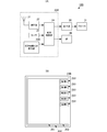
- FIG. 21A is a block diagram showing a main configuration of a ship according to the third embodiment of the present invention
- FIG. 21B is a diagram showing a display screen example
- FIG. 22 is a flowchart of the marine vessel maneuvering control determination process by fish species.
- the hull control device and hull control method of the present embodiment are obtained by adding a boat maneuvering selection function based on fish types to the hull control device and hull control method shown in the first embodiment.
- the hull control device 20B of the ship 10B according to the present embodiment is provided with a display unit 25B with an operation function with respect to the hull control device 20 according to the first embodiment.
- the display unit 25B with an operation function includes a touch panel, and accepts an operation input when the user operates the display surface.
- the display unit 25B with an operation function includes a display screen 250 having a mode as shown in FIG.
- the display screen 250 includes an information display unit 251 that displays detection data, acquired information, and the like, and an operation input unit 252.
- the operation input unit 252 has a plurality of operation tabs 253 each displaying a fish species name.
- Each ship maneuvering tab 253 is associated with an individually set fish type.
- information such as points, a ship maneuvering method, and a fixed point type are associated with each fish type.
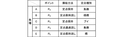
- FIG. 23 is a table showing an example of associating fish species with points, ship maneuvering methods, and fixed point types.
- the point indicates a position where the fishing result of the selected fish type is high, and can correspond to the above-described fixed point position Pp.
- the ship maneuvering method indicates the movement and holding mode of the ship with respect to the fixed point position Pp such as the above-mentioned “fixed point holding”, “fixed point holding sink”, “fixed point passing sink” and the like.
- the fixed point type indicates the type of an object existing at a fixed point position Pp such as “fish reef”, “pier”, “buoy”, “bridge”, and the like.
- a marine vessel maneuvering control signal including information such as a point, a marine vessel maneuvering method, and a fixed point type associated with the fish type of the operation tab 253 is generated and output to the hull control unit 24.
- the hull control unit 24 executes appropriate ship maneuvering control, for example, navigation control to the above-mentioned fixed point position and fixed point holding control in accordance with the ship maneuvering control signal.
- Such ship maneuvering control processing is executed by the following flow.
- the display screen 250 with the operation input unit 252 which is a fish type selection screen is displayed (S931).
- the operation input waiting state is maintained while displaying the fish type selection screen.
- the content of the boat maneuvering control according to the selected fish type is selected (S933).
Landscapes
- Engineering & Computer Science (AREA)
- Chemical & Material Sciences (AREA)
- Ocean & Marine Engineering (AREA)
- Mechanical Engineering (AREA)
- Combustion & Propulsion (AREA)
- Remote Sensing (AREA)
- Automation & Control Theory (AREA)
- General Physics & Mathematics (AREA)
- Physics & Mathematics (AREA)
- Radar, Positioning & Navigation (AREA)
- Aviation & Aerospace Engineering (AREA)
- Navigation (AREA)
- Traffic Control Systems (AREA)
- Position Fixing By Use Of Radio Waves (AREA)
Abstract
【課題】左右動を行うための大がかりな追加装備を行わなくても、同等の船体制御が可能な船体制御方法を提供する。 【解決手段】定点位置Ppを設定するとともに、自船位置Ps、外乱方位ADd、船首方位ADbを順次取得する。定点位置Ppにおいて外乱方位ADdと船首方位ADbとが略一致するように、定点位置Ppに向けて船10を航行させる(S101)。船10が定点位置Ppに到着するまでは(S102:No)、この航行を継続する。船10が定点位置Ppに到着すると(S102:Yes)、外乱方位ADdと船首方位ADbとを略一致させた状態で、舵角の調整と船10の前進もしくは後進とを組み合わせて、外乱対向ライン方向の定点位置Ppを含む所定範囲内に船10を保持する。
Description
本発明は、船を定点に移動させたり、船を定点に保持するための船体制御方法に関する。
従来、漁の効率を向上させる等の目的のために、漁師は、予め目的の魚が多く生息すると考えられる位置(例えば、魚礁や瀬)において漁を行っている。この場合、例えば、当該位置にて船舶を定点保持した状態で漁を行ったり、当該定点を通過しながら漁を行うことで、より効率的な漁が実現できる。
また、このような目的位置(定点位置)にできる限り効率良く到達することも漁の効率を向上させるためには必要である。
しかしながら、海上では、風や潮流等による外乱を船体が受けて、定点位置から流されてしまったり、定点位置まで効率良く航行できないことがある。
このため、従来、風や潮流を受けても、船舶を定点に留めたり、定点への移動時には定点方向に船首方向が向くようにする船体制御方法が各種考案されている。たとえば、特許文献1に示す船舶では、サイドスラスターを備えている。サイドスラスターとは、船体を横方向、すなわち右舷左舷方向へ移動させるための機構である。また、従来の船舶には、このような横方向の移動を実現するために、水平方向に回動可能なプロペラを備えるものもある。
しかしながら、上述のようなサイドスラスターや、右左舷方向に回動可能なプロペラは、非常に大がかりなものであり、コストも高く、経済性を重視する漁船の場合には、大幅なコスト高となるため、これらサイドスラスターや右左舷方向に回動可能なプロペラを、容易に装備することができない。
したがって、プレジャーボートや小型漁船では、サイドスラスターや右左舷方向に回動可能なプロペラ等の大がかりな追加装備を行うことなく、船を定点保持する船体制御を行う必要がある。
また、プレジャーボートや小型漁船では、サイドスラスターや右左舷方向に回動可能なプロペラ等の大がかりな追加装備を行うことなく、船を定点に効率良く航行させる船体制御を行う必要がある。この際、単に定点に船を移動させるだけでは、定点到着時の船の姿勢によっては外乱の影響を大きく受け、サイドスラスターや右左舷方向に回動可能なプロペラ等の大がかりな追加装備を行っていなければ、定点保持が容易に行えなくなることがあり、定点到着時の船の姿勢は重要である。
この発明の目的は、サイドスラスターや右左舷方向に回動可能なプロペラ等の大がかりな追加装備を行わなくても、これら追加装備と同等の船体制御が可能な船体制御方法を提供することにある。
この発明の船体制御方法は、自船位置を取得する工程と、自船を基準として該自船に対して外からの力を与える外乱の方向である外乱方位を検出する工程とを有する。船体制御方法は、予め設定した定点位置と自船位置とから定点位置に向かう目標方位を算出する工程と、外乱方位から定点位置での目標方位を検出する工程とを有する。船体制御方法は、定点位置に向かう目標方位と定点位置での目標方位とから、その時点での自船の航行する方位である航行方位を算出する工程と、航行方位に応じて舵角を調整する工程と、を有する。
この方法では、自船が定点位置に近づくにつれて、船首方位と外乱方位とが徐々に略一致していくように、船を定点位置に向けて航行させることができる。
また、この発明の船体制御方法の航行方位を算出する工程は、定点位置に向かう目標方位と定点位置での目標方位との重み付け加算によって航行方位を算出する。重み付け加算は、自船が定点位置に近づくほど定点位置の船首方位の重みが重くなるように設定されている。
この方法では、航行方位の具体的な算出例を示している。
また、この発明の船体制御方法は、外乱の大きさを検出する工程と、外乱の大きさから前記定点位置での目標船速を算出する工程とを有する。船体制御方法は、自船を定点位置に向かわせる目標船速と、定点位置での目標船速とから、その時点での自船の航行する速度である航行船速を算出する工程と、航行船速に応じて推力を調整する工程と、を有する。
この方法では、自船を定点位置に到達させるための目標船速と定点位置での目標船速とから最適な航行船速が決定される。
また、この発明の船体制御方法の航行船速を算出する工程は、目標船速と定点位置の船速との重み付け加算によって、航行船速を算出する。重み付け加算は、自船が定点位置に近づくほど定点位置の船速の重みが重くなるように設定されている。
この方法では、航行船速の具体的な算出例を示している。
また、この発明の船体制御方法は、自船位置を取得する工程と、自船を基準として該自船に対して外からの力を与える外乱の方向である外乱方位を検出する工程と、を有する。船体制御方法は、外乱方位に対して直交し定点位置を通る外乱直交ラインを設定する工程と、推力と舵角を調整することにより、外乱直交ラインと自船位置との関係から外乱方位に略平行な方向に沿って自船を前進もしくは後進させる工程と、を有する。
この方法では、船首方位と外乱方位とを略一致させた状態で、自船を定点位置付近に留めることができる。
また、この発明の船体制御方法は、自船の船首方位を検出する工程を有する。船体制御方法の自船を前進もしくは後進させる工程は、自船の船首方位と外乱方位とが略一致する場合に、自船位置が外乱直交ラインに対して外乱側にあるときに自船を後進させ、自船位置が外乱直交ラインに対して外乱と反対側にあるときに自船を前進させる。
この方法では、前後進を切り替えるための具体的な方法を示している。
また、この発明の船体制御方法は、外乱方位に平行な外乱対向ライン上において船が定点位置から最も離間する距離を検出する工程と、最も離間する距離が外乱の大きさによって決定される推力調整用の閾値距離よりも長い場合に船の推力を低減させる工程を、有する。
また、この発明の船体制御方法は、外乱方位に平行な外乱対向ライン上において船が定点位置から最も離間する距離を検出する工程と、最も離間する距離が外乱の大きさによって決定される推力調整用の閾値距離よりも短い場合に船の推力を上昇させる工程を、有する。
これらの方法では、前後進時の具体的な推力調整方法を示している。これらの方法を用いることにより、船を定点位置の付近に、より正確に留めることができる。
また、この発明の船体制御方法は、外乱方位に平行な外乱対向ライン上において船が定点位置から最も離間する距離を検出する工程と、最も離間する距離に基づいて推力をオンさせるタイミングとオフさせるタイミングのいずれか一方を調整する。
この方法では、定点位置に対する船の移動範囲を、さらに狭くすることができる。
また、この発明の船体制御方法は、船首方位と外乱方位との差分が閾値以下の場合に自船を前進もしくは後進させる工程を実行する。
この方法では、船首方位と外乱方位との差分が小さい時にのみ、上述の船を定点位置付近に留める前後進制御が行われる。これにより、船を定点位置付近に、さらに確実に留めることができる。
また、この発明の船体制御方法は、船首方位と外乱方位との差分が閾値より大きな場合に船首方位を変更する工程を実行する。
この方法では、船首方位と外乱方位との差分が大きくても、その差分が小さくなるように、船首方位を容易に変更することができる。
また、この発明の船体制御方法の船首方位を変更する工程は、船を後進させながら舵角を調整して船首方位と外乱方位とを近づける工程と、船を前進させながら舵角を調整して船首方位と外乱方位を近づける工程と、を有する。
この方法では、船首方位の変更の具体的な方法を示している。そして、この方法を用いることで、外乱を利用して、船首方位を容易に変更することができる。
また、この発明の船体制御方法は、自船位置が、定点位置を中心とする所定距離範囲内にある場合に、船を前進もしくは後進させる工程を実行する。この船体制御方法は、自船位置が所定範囲から外れる場合に、次の各工程を有する。この船体制御方法は、定点位置と自船位置とから前記定点位置に向かう目標方位を算出する工程と、外乱方位から定点位置での目標方位を検出する工程と、定点位置に向かう目標方位と定点位置での目標方位とから、その時点での自船の航行する方位である航行方位を算出する工程を有する。この船体制御方法は、外乱の大きさを検出する工程と、外乱の大きさから定点位置の船速を算出する工程と、自船を定点位置に向かわせる船速である目標船速と、定点位置での目標船速とから、その時点での自船の航行する速度である航行船速を算出する工程を有する。この船体制御方法は、航行方位に応じた舵角を調整し、航行船速に応じて推力を調整する工程を有する。
この方法では、自船位置が定点位置に近い場合に、上述の定点位置付近に船を留める前後進制御が行われ、自船位置が定点位置から離れた場合に、上述の定点位置に向けて船を航行させる制御が行われる。これにより、状況に応じて、船を適切に定点位置に移動させるか、定点位置付近に留まらせることができる。
また、この発明の船体制御方法は、推力と舵角の調整を異なるタイミングで実行してもよい。
この方法では、推力と舵角の調整を同時に行わないため、目標とする船の移動を、より安定して実現することができる。
また、この発明の船体制御方法は、推力および舵角は離散的な値に設定してもよい。
この方法では、アナログ的な推力制御や舵角制御と略同等な移動を可能としながら、推力制御および舵角制御が容易になる。
また、この発明の船体制御方法は、自船位置と定点位置との距離に応じて通知を行う工程を、有する。通知は、距離によって異なるように設定されている。
この方法では、ユーザに、自船と定点との距離を直感的に理解させることができる。
また、この発明の船体制御方法は、魚種によって操作入力を受け付ける工程と、魚種に関連付けられた操業態様を選択する工程と、選択された操業態様に基づいて前記自船の制御を行う工程と、を有する。
この方法では、ユーザが船の移動のさせ方を直感的に選択することができる。
この発明によれば、右左舷方向への移動が可能な追加装備を行わなくても、外乱の影響による不要な船の動きを抑制して、所望の船体制御が可能になる。
本発明の第1の実施形態に係る船体制御装置を備える船体制御方法について、図を参照して説明する。図1は本発明の第1の実施形態に係る船の主要構成を示すブロック図である。
船10は、船体制御装置20、動力源30、プロペラ31、および舵40を備える。船体制御装置20は、アンテナ21、測位部22、センサ23、船体制御部24、および操作部25を備える。動力源30およびプロペラ31の組が「推進力発生部」に相当する。
アンテナ21は、GPS測位信号を受信し、測位部22へ出力する。測位部22Aは、GPS測位信号を用いて測位演算を実行し、船10の位置(自船位置)Psを算出する。この測位演算は、予め設定した測位タイミング毎に実行される。測位部22は、算出した自船位置Psを、船体制御部24へ出力する。
センサ23は、例えば、船首方位ADbを検出するヘディングセンサ、風向センサ、風速センサ、潮流計等を備える。センサ23は、風向、風速、潮流方向、潮流速度から外乱ベクトルVECdを算出する。外乱ベクトルVECdは、風ベクトルVECwと、潮流ベクトルVECtとの加算ベクトルによって定義される。風ベクトルVECwのベクトル方向は、風向によって決定され、風ベクトルVECwの大きさは、風速によって決定される。潮流ベクトルVECtのベクトル方向は、潮流方向によって決定され、潮流ベクトルVECtの大きさは、潮流速度によって決定される。
センサ23は、検出した船首方向ADb、外乱ベクトルVECdを、船体制御部24へ出力する。なお、センサ23は、風ベクトルVECwや潮流ベクトルVECtを、船体制御部24に出力しても良い。また、センサ23が風ベクトルVECwや潮流ベクトルVECtを船体制御部24に出力し、船体制御部24が風ベクトルVECwや潮流ベクトルVECtから外乱ベクトルVECdを算出してもよい。
船体制御部24は、予め操作部25を介してユーザが設定した定点位置Ppを記憶している。具体的な制御方法は後述するが、船体制御部24は、定点位置Ppと自船位置Psとに基づいて、定点位置への航行制御もしくは定点保持制御を実行する。概略的には、定点位置Ppと自船位置Psとの距離DISが所定値よりも大きい場合には、定点位置への航行制御を行い、距離DISが所定値以下の場合には、定点保持制御を行う。
船体制御部24は、定点位置への航行制御もしくは定点保持制御で決定した推力に基づいて動力源30の駆動制御を行う。船体制御部24は、定点位置への航行制御もしくは定点保持制御で決定した舵角に基づいて舵40の舵角制御を行う。
操作部25は、所謂ユーザインターフェース機器であり、ユーザによる操作入力を、船体制御部24へ出力する。
動力源30は、ディーゼルエンジンやモータからなる。また、これらディーゼルエンジンとモータを備え、状況に応じて使い分けるハイブリッド動力機構であってもよい。動力源30は、船体制御部24によって駆動制御される。動力源30は、発生した動力をプロペラ31に与える。
舵40は、船10の船尾に備え付けられている。舵40は、船体制御部24によって舵角制御される。
このような構成から、船10は、プロペラ31の推進力と、舵40の舵角によって、定点へ航行したり、定点保持するように前進もしくは後退する。なお、この際、後退は、プロペラ31を停止させて外乱によって後退する場合も含む。
そして、このような構成からなる船10は、概略的には、図2に示すようなフローで船体制御を行う。図2は本発明の実施形態に係る船体制御のフローチャートである。なお、図2では、自船位置Psと定点位置Ppとの距離DISが所定値よりも離間している場合について示している。ここで、距離DISが所定値以下の場合には、定点位置への移動制御は行われず、定点保持制御となる。
まず、船体制御部24は、自船位置Ps、定点位置Pp、外乱ベクトルVECd、および船首方位ADbに基づいて、定点位置Ppに向かって船10を航行させるように推力制御と舵角制御を行う。この際、船体制御部24は、外乱ベクトルVECdの向く方向と逆方向で且つ定点位置Ppを基点する方位を外乱方位ADdとして検出する。そして、船体制御部24は、定点位置Ppにおいて船首方位ADbと外乱方位ADdとが略一致するように、推力制御と舵角制御をしながら船10を航行させる(S101)。
この航行制御は、自船位置Psと定点位置Ppとが略一致するまで継続的に実行させる(S102:No→S101)。
自船位置Psと定点位置Ppとが略一致したことを検出すると(S102:Yes)、船体制御部24は、船首方位ADbと外乱方位ADdとが略一致した状態を維持しながら定点位置Psおよび定点位置Psの近傍領域に船10が留まり続けるように、推力制御と舵角制御を行い、定点保持制御を行う(S103)。
次に、定点位置Ppへの航行制御の具体的方法について、図を参照して説明する。図3は定点位置Ppへの航行制御のフローチャートである。図3に示す航行制御は、定点位置Ppへの航行を介して、定点位置Ppに到達するまでの間、所定の時間間隔で、継続的に行われる。図4は定点位置Ppへの航行制御に用いる各パラメータの関係を示す図である。図5は本発明の航行制御を行った場合の航跡例を示す図である。図6は重み付けの設定例を示す図である。なお、特にことわりをおかなければ、以下に示す速度は絶対速度(対地速度)であり、座標は地球表面の絶対座標であり、方位は、北基準の方位である。
定点位置Ppへの航行制御は、まず、自船位置Psと定点位置Ppとを取得する(S111)。定点位置Ppの取得は、ユーザが操作部25によって、定点位置Ppの座標を指定することにより実行される。なお、定点位置Ppの取得は、定点位置Ppへの航行開始のタイミングのみで行えばよい。自船位置Psは、上述の測位部22による測位結果により取得される。自船位置Psと定点位置Ppとを取得すると、この二点間の距離、すなわち、この時点での自船位置Psから定点位置Ppまでの距離DISが算出される。
次に、外乱要素の各パラメータを取得する(S112)。外乱は、風と潮流との合成で表され、速度ベクトルによって表現できる。風ベクトルVECwは、センサ23で計測した風向、風速から取得される。潮流ベクトルVECtは、センサ23で計測した潮流方向、潮流速度から取得される。外乱ベクトルVECdは、風ベクトルVECwと潮流ベクトルVECtとの合成ベクトルとして得られる。したがって、外乱ベクトルVECdは、風ベクトルVECwと潮流ベクトルVECtとベクトル加算により算出される。
なお、この際、センサ23は船10に装着されているため、算出される外乱ベクトルVECdは自船位置Psのものであるが、この外乱ベクトルVECdを、定点位置Ppの外乱ベクトルVECdと見なす。このような方法を用いても、実際に、船10が定点位置Ppに近づけば、自船位置Psと定点位置Ppとが略一致するので、自船位置Psの外乱ベクトルVECdを定点位置Ppの外乱ベクトルVECdとしても、十分な精度での航行制御が可能である。また、自船位置Psと定点位置Ppが離れていたとしても、外乱ベクトルVECdは大きく変化することはなく、さらに、定点位置Ppに向かって航行するにつれ、自船位置Psの外乱ベクトルVECdと定点位置Ppの外乱ベクトルVECdとの間に殆ど差が無くなるので、十分な精度での航行制御が可能である。
次に、自船位置Psを基準とした定点位置Ppに向かう目標方位ψp、定点位置Ppに向かう目標船速Vp、定点位置Ppでの目標方位ψd、および目標船速(定点船速)Vdを取得する(S113)。
定点位置に向かう目標方位ψpは、自船位置Psの座標と定点位置Ppの座標とから幾何学計算により算出される。また、ユーザが操作部25を操作することで、定点位置Ppに向かう目標船速Vp、を取得する。
また、ユーザが操作部25を操作することで、定点位置Ppでの目標方位ψd、および目標船速(定点船速)Vdを取得する。定点位置Ppでの目標方位ψdは、外乱ベクトルVECdの方位と対向する方位に設定される。定点位置Ppでの船速Vdは、例えば、外乱ベクトルVECdの大きさと同じ大きさに設定される。この場合、定点位置Ppでの対地船速は0になるように設定される。
次に、定点位置に向かう目標方位ψpと定点位置での目標方位ψdとを用いて、その時点での航行方位ψoを決定する(S114)。
この際、次の重み付け加算式を用いて、航行方位ψoを算出する。
ψo=αψp+βψd ここで、α+β=1である。また、定点位置Ppへの航行開始タイミングでの自船位置Psと定点位置Ppとの距離をDISoとし、その時点での距離をDISとした場合に、αは次のように定義される。
α=1-exp-(DIS/DISo) したがって、βは次式で表される。
β=exp-(DIS/DISo) このようなα,βは、距離DISに応じて、図6のように変化する。すなわち、αは、距離DISが短くなるほど小さくなり、βは距離DISが長くなるほど大きくなる。
このような式で航行方位ψoを算出することで、航行方位ψoは、定点位置Ppから遠いほど定点位置に向かう目標方位ψpに近づき、定点位置Ppに近づくほど定点位置での目標方位ψdに近づくように、徐々に変化する。これにより、定点位置に向かう目標方位ψpから定点位置での目標方位ψdに航行方位ψoを滑らかに変化させながら、定点位置Ppに向かって船10を航行させることができる。
次に、定点位置に向かう目標船速Vpと定点位置での目標船速Vdとを用いて、その時点での航行船速Voを決定する(S115)。
この際、次の重み付け加算式を用いて、航行船速Voを算出する。
Vo=αVp+βVd ここで、α、βは、上述の航行方位ψoと同じ定義である。
このような式で航行船速Voを算出することで、航行船速Voは、定点位置Ppから遠いほど定点位置に向かう目標船速Vpに近づき、定点位置Ppに近づくほど定点位置での目標船速Vdに近づくように、徐々に変化する。これにより、定点位置に向かう目標船速Vpから定点位置での目標船速Vdに航行船速Voを滑らかに変化させながら、定点位置Ppに向かって船10を航行させることができる。
次に、算出した航行船速Voを用いて、動力源30に与える推力を決定する。また、算出した航行方位ψoを用いて、舵40に与える舵角を決定する(S116)。
以上のような処理を行うことで、図5に示すように、定点位置Ppへの航行開始位置から定点位置Ppに向かって、外乱に流されながらも、徐々に船首方位が外乱方位に対向(平行)するように変化しながら、船10を定点位置Ppまで航行することができる。そして、船10は定点位置Ppに到達した時点で、船首方位を外乱方位に対向させることができる。このように、定点位置Ppにおいて、船首方位と外乱方位とを対向させる(外乱ベクトルの方向と船首方向との成す角が180°)ことで、一動力、一舵の船10であっても、次に示す定点保持の制御の開始を容易にすることができる。
上述の説明では、船体制御部24を1つの素子として、各処理を行う場合を示したが、図7に示すように、複数の機能部に分割して、上述の処理を行ってもよい。図7は、船体制御部24の方位船速設定部41の構成を示すブロック図である。
方位船速設定部41は、航行条件決定部42と、重み付け処理部43を備える。航行条件決定部42は、定点方向ベクトル算出部421と定点位置ベクトル算出部422を備える。
定点方向ベクトル算出部421は、定点位置Ppと自船位置Psとから定点位置に向かう目標方位ψpを算出する。また、定点方向ベクトル算出部421は、操作入力に基づいて定点位置に向かう目標船速Vpを決定する。
定点位置ベクトル算出部422は、外乱ベクトルVECdから定点船速Vdを算出する。また、定点位置ベクトル算出部422は、操作入力に基づいて定点船速Vdを決定する。
重み付け処理部43は、重み付け係数設定部433、乗算器4341,4342,4343,4344、加算器4351,4352を備える。
重み付け係数設定部433は、距離DISに基づいて重み付け係数α,βを決定する。
乗算器4341には、定点位置に向かう目標方位ψpと重み付け係数αが与えられる。この際、定点位置に向かう目標方位ψpは単位ベクトル化された後に与えられる。乗算器4341は、定点位置に向かう目標方位ψpに重み付け係数αを乗算して、乗算結果αψpを加算器4351に出力する。
乗算器4342には、定点位置での目標方位ψdと重み付け係数βが与えられる。この際、定点位置での目標方位ψdは単位ベクトル化された後に与えられる。乗算器4342は、定点位置での目標方位ψdに重み付け係数βを乗算して、乗算結果βψdを加算器4351に出力する。
加算器4351は、乗算結果αψpと乗算結果βψdとを加算して、航行方位ψ0を算出し、出力する。
乗算器4343には、定点位置に向かう目標船速Vpと重み付け係数αが与えられる。乗算器4343は、定点位置に向かう目標船速Vpに重み付け係数αを乗算して、乗算結果αVpを加算器4352に出力する。
乗算器4344には、定点位置での目標船速Vdと重み付け係数βが与えられる。乗算器4344は、定点位置での目標船速Vdに重み付け係数βを乗算して、乗算結果βVdを加算器4352に出力する。
加算器4352は、乗算結果αVpと乗算結果βVdとを加算して、航行船速Voを算出し、出力する。
このような構成であっても、上述のように、徐々に船首方位が外乱方位に対向(平行)するように変化しながら、船10を定点位置Ppまで航行することができる。
次に、定点位置Ppに到達した船10を、定点位置Ppに保持する定点保持制御について説明する。図8は定点保持制御のフローチャートである。図9は前後進の切り替え概念を示す図である。なお、以下、定点保持制御状態では、船首方位をADbとし、外乱方位(外乱ベクトルVECdに対向する方位)をADdとして説明する。また、以下の説明では、船首が外乱方向を向いている場合を示す。なお、船尾が外乱方向を向いている場合には、後述の前進制御と後進制御が逆になる。
定点位置Ppの到達は、測位した自船位置Psと定点位置Ppとが略一致したことによって検出できる。ここで、自船位置Psと定点位置Ppとが略一致するとは、例えば、定点位置Ppを中心とする所定範囲内に自船位置Psが入ったことを意味している。具体的な例としては、定点位置Ppを中心として、船10の3艇身分程度の長さを半径とする円内の領域に、自船位置Psが入ったことを意味している。この領域を、以下、定点保持動作領域BorK(図9参照)とする。この範囲が、定点位置Ppの近傍となる。なお、この半径等は使用態様等に応じて適宜設定すればよい。
自船位置Psが定点保持領域BorK内にないことを検出すると(S211:No)、上述のように、定点位置Ppにおいて、船首方位ADbが外乱ベクトルVECdの方向と対向するように、言い換えれば外乱方位ADdと平行になるように、船10を航行制御する(S215)。
自船位置Psが定点保持領域BorK内にあることを検出すると(S211:Yes)、以下の定点保持制御を実行する。
具体的には、自船位置Psが定点保持領域BorK内にあることを検出すると(S211:Yes)、外乱方位ADdと船首方位ADbとの誤差角Δψddを算出する(S212)。誤差角Δψddは、例えば、外乱方位ADdから船首方位ADbを減算することによって得られる。なお、逆、すなわち、船首方位ADbから外乱方位ADdを減算してもよい。
外乱ベクトルVECdが一定で変化しない場合、定点位置Ppに到達した時点で、外乱方位ADdと船首方位ADbは平行なはずであり、外乱が変化しなければ誤差角Δψddは定常的に0になるはずである。しかしながら、外乱は、風と潮流によって決定されるので、頻繁に変化する。したがって、後述の定点保持制御を行うために、船首方位ADbを外乱方位ADdと平行にするためには、このような誤差角Δψddの変化を検出する必要がある。
誤差角Δψddには、予め設定された誤差角閾値ThΔψddが設定されている。誤差角閾値ThΔψddは、後述の前後進制御により定点保持が容易に行えるような外乱方位ADdと船首方位ADbとの角度差(誤差角Δψdd)の最大値によって決定される。この最大値は、予め実験等によって設定することができる。具体的な例としては、誤差角閾値ThΔψddは、±45°に設定される。
誤差角Δψddが誤差角閾値ThΔψddよりも大きければ(S213:No)、後述する方位変更制御を実行する(S218)。誤差角Δψddが誤差角閾値ThΔψdd以下であれば、自船位置Psが外乱直交ラインLverに対して、外乱側であるか、外乱側でないかを検出する。
外乱直交ラインLverは、外乱ベクトルVECdに直交し、且つ定点位置Ppを通る直線によって定義される。外乱直交ラインLverを基準として外乱側で且つ定点保持領域BorKの領域を、外乱上領域ZoneUとする。外乱直交ラインLverを基準として外乱と反対側で且つ定点保持領域BorKの領域を、外乱下領域ZoneDとする。
自船位置Psが外乱上領域ZoneUにあることを検出すると(S214:Yes)、定点保持用後進制御を行う(S217)。定点保持用後進制御とは、船10を保持用船速で後進させる制御であり、推力を発生して後進用にスクリューを回転させたり、推力を発生せずに外乱に流されるようにする制御である。なお、この定点保持用後進制御中に、舵角を適宜調整して船首方位ADbを外乱方位ADdと平行になるように、調整してもよい。
自船位置Psが外乱下領域ZoneDにあることを検出すると(S214:No)、定点保持用前進制御を行う(S216)。定点保持用前進制御とは、船10を保持用船速で前進させる制御である。なお、この定点保持用前進制御中に、舵角を適宜調整して船首方位ADbを外乱方位ADdと平行になるように、調整してもよい。
このような制御を行うことで、船10が外乱上領域ZoneUに存在する場合には、定点保持領域BorK内の外乱直交ラインLver、より好ましくは定点位置Ppそのものに到達するように、船10を後進させることができる(図9の船10'参照)。また、船10が外乱下領域ZoneDに存在する場合にも、定点保持領域BorK内の外乱直交ラインLver、より好ましくは定点位置Ppそのものに到達するように、船10を前進させることができる(図9の船10"参照)。すなわち、船10を定点位置Pp付近の狭い範囲に留まらせることができる。さらに、一動力、一舵の船10であっても、船10の位置に応じて定点位置Ppに到達するように、自動で船10を移動させることができる。
次に、上述の前後進制御を更に具体的に説明する。図10は、前後進時の推力制御方法を示すフローチャートである。図11は推力制御概念を示す図である。図11では、横軸が時間であり、縦軸が外乱対向ライン射影距離Ldであり、実線は航跡の時間変化を示す。
外乱対向ライン射影距離Ldとは、図9の船10'の場合に示すように、自船位置Psと定点位置Ppとの距離を、外乱対向ラインに射影した距離である。外乱対向ラインとは、外乱直交ラインLverに直交し(外乱方位ADdに平行であり)、定点位置Ppを通る直線である。なお、図9の場合では、外乱対向ライン上に船10'が存在する場合を示したが、それ以外の場合も同様の方法で、外乱対向ライン射影距離Ldを定義できる。
また、図10の推力制御方法では、図11に示すように、外乱下領域ZoneDから外乱上領域ZoneUに船10を移動させる際の外乱直交ラインLverを交差した時点で推力をオフにし、外乱上領域ZoneUから外乱下領域ZoneDに船10を移動させる際の外乱直交ラインLverを交差した時点で推力をオンにする。
外乱下領域ZoneDに存在する船10に対して推力を発生して当該船10を前進させると、外乱直交ラインLverと交差する時点で推力をオフにしても、船10は前進を続ける。そして、保持用船速による推力の外乱対向ライン方向成分と外乱の外乱対向ライン方向成分とが一致する位置で船10の船速は0となり、外乱に流されるように後進する。
この船速が0となる位置と定点位置Ppとを結ぶ線分を外乱対向ラインに射影させた長さを、外乱対向ライン最大射影距離Lddとして算出する(S311)。
外乱対向ライン最大射影距離Lddに対しては、予め設定された推力調整閾値ThLddが設定されている。推力調整閾値ThLddは、船10の推力、形状、外乱ベクトルVECdの大きさ、定点位置Ppに対してどれだけ船10が離れても許容させるか等によって設定される。
外乱対向ライン最大射影距離Lddが推力調整閾値ThLddよりも長いことを検出すると(S312:Yes)、推力低減制御を行う(S313)。推力低減制御は、次回の推力を今回の推力よりも低くする制御である。例えば、今の推力をVt(n)とし、次回の推力をVt(n+1)とし、補正量をδVtとすると、
Vt(n+1)=Vt(n)-δVt によって算出する。補正量δVtは、例えば、ユーザによって適宜設定可能な値である。
Vt(n+1)=Vt(n)-δVt によって算出する。補正量δVtは、例えば、ユーザによって適宜設定可能な値である。
外乱対向ライン最大射影距離Lddが推力調整閾値ThLddよりも短いことを検出すると(S312:No,S314:Yes)、推力上昇制御を行う(S315)。推力上昇制御は、次回の推力を今回の推力よりも高くする制御である。例えば、今の推力をVt(n)とし、次回の推力をVt(n+1)とし、補正量をδVtとすると、
Vt(n+1)=Vt(n)+δVt によって算出する。
Vt(n+1)=Vt(n)+δVt によって算出する。
外乱対向ライン最大射影距離Lddが推力調整閾値ThLddより短くもなく、長くもない場合、すなわち、外乱対向ライン最大射影距離Lddが推力調整閾値ThLddが一致する場合には(S312:No,S314:No)、推力を変更しない。
このような制御を行うことで、図11に示すように、船10は移動する。
まず、外乱下領域ZoneDから推力オンVt11状態で船10が外乱方向へ移動し、外乱直交ラインLverを横切った時刻t11で推力をオフにすると、これまでに加わった推力に応じて、船10は前進する。そして、船10は、外乱対向ライン最大射影距離Ldd(t11)で一時停止する。ここでは、外乱対向ライン最大射影距離Ldd(t11)が推力調整閾値ThLddより長いので、次回の推力Vt12を今回の推力Vt11からδVt低減させる。
この後、船10は、外乱により流されて外乱直交ラインLverをよこぎると、このタイミングで推力Vt12をオンにする。船10は、外乱下領域ZoneDに流されるが、推力Vt12により再度外乱側に折り返し移動する。
次に、外乱下領域ZoneDから推力オンVt12状態で船10が外乱方向へ移動し、外乱直交ラインLverを横切った時刻t12で推力をオフにすると、外乱対向ライン最大射影距離Ldd(t12)まで到達し、一時停止する。ここでは、外乱対向ライン最大射影距離Ldd(t12)が推力調整閾値ThLddよりまだ長いので、次回の推力Vt13を今回の推力Vt12からさらにδVt低減させる。
この後、船10は、外乱により流されて外乱直交ラインLverをよこぎると、このタイミングで推力Vt13をオンにする。船10は、外乱下領域ZoneDに流されるが、推力Vt13により再度外乱側に折り返し移動する。
次に、外乱下領域ZoneDから推力オンVt13状態で船10が外乱方向へ移動し、外乱直交ラインLverを横切った時刻t13で推力をオフにすると、外乱対向ライン最大射影距離Ldd(t13)まで到達し、一時停止する。ここでは、外乱対向ライン最大射影距離Ldd(t13)が推力調整閾値ThLddよりまだ長いので、次回の推力Vt14を今回の推力Vt13からさらにδVt低減させる。
この後、船10は、外乱により流されて外乱直交ラインLverをよこぎると、このタイミングで推力Vt14をオンにする。船10は、外乱下領域ZoneDに流されるが、推力Vt14により再度外乱側に折り返し移動する。
次に、外乱下領域ZoneDから推力オンVt14状態で船10が外乱方向へ移動し、外乱直交ラインLverを横切った時刻t14で推力をオフにすると、外乱対向ライン最大射影距離Ldd(t14)まで到達し、一時停止する。ここでは、外乱対向ライン最大射影距離Ldd(t14)が推力調整閾値ThLddより短いので、次回の推力Vt15を今回の推力Vt14からδVt上昇させる。
この後、船10は、外乱により流されて外乱直交ラインLverをよこぎると、このタイミングで推力Vt15をオンにする。船10は、外乱下領域ZoneDに流されるが、推力Vt15により再度外乱側に折り返し移動する。
次に、外乱下領域ZoneDから推力オンVt15状態で船10が外乱方向へ移動し、外乱直交ラインLverを横切った時刻t15で推力をオフにすると、外乱対向ライン最大射影距離Ldd(t15)まで到達し、一時停止する。ここでは、外乱対向ライン最大射影距離Ldd(t14)が推力調整閾値ThLddより長いので、次回の推力Vt16を今回の推力Vt15からδVt低減させる。
この後、船10は、外乱により流されて外乱直交ラインLverをよこぎると、このタイミングで推力Vt16をオンにする。船10は、外乱下領域ZoneDに流されるが、推力Vt16により再度外乱側に折り返し移動する。
このように、上述の定点保持制御を行うことで、船10は、外乱直交ラインLver(定点位置Pp)を中心として、推力調整閾値ThLddの約2倍の範囲で、前後進するように、徐々に移動範囲を狭くすることができる。さらに、船10は、外乱直交ラインLverを中心として、推力調整閾値ThLddの約2倍の範囲で、前後進を繰り返すようにすることができる。
なお、推力調整閾値ThLddを徐々に小さく設定する推力調整閾値ThLddの適応処理も可能であり、このような適応処理を行うことで、船10の移動範囲を、定点位置Ppを中心とする更に短い範囲にすることができる。
なお、このような定点保持制御も1つの演算素子でなく、複数の機能部で実現する異ができる。図12は、定点保持制御部の構成を示すブロック図である。
定点保持制御部44は、誤差角検出部441、前後進決定部442、推力、舵角決定部443を備える。誤差角検出部441は、外乱方位ADdと船首方位ADbとから誤差角Δψddを算出する。前後進決定部442は、外乱方位ADdと定点位置Ppとから外乱直交ラインLverを設定する。前後進決定部442は、定点位置Ppから定点保持領域BorKを決定する。
前後進決定部442は、定点保持領域BorK、外乱直交ラインLver、および自船位置Psから、上述の定点位置への航行制御、定点保持用の前進制御、定点保持用の後進制御のいずれかを選択する。前後進決定部442は、自船位置Psが定点保持領域BorK外であれば、定点位置への航行制御を選択する。前後進決定部442は、自船位置Psが定点保持領域BorK内であり、且つ外乱直交ラインLverに基づく外乱上領域ZoneU内であれば、定点保持用の後進制御を選択する。前後進決定部442は、自船位置Psが定点保持領域BorK内であり、且つ外乱直交ラインLverに基づく外乱下領域ZoneD内であれば、定点保持用の前進制御を選択する。
推力、舵角決定部443は、選択された制御と、誤差角Δψddとから推力、および舵角を決定する。
このような構成であっても、上述のように、定点保持制御を行うことができる。
次に、別の定点保持制御方法について具体的に説明する。図13は、推力オンオフタイミングを調整する定点保持制御のフローチャートである。図14は、推力オンオフタイミングの調整による定点保持制御の概念を示す図である。図14において、横軸が時間であり、縦軸が外乱対向ライン射影距離Ldであり、実線は航跡の時間変化を示す。
なお、以下の説明では、自船が推力オン状態からオフ状態に切り替わったタイミングからを説明する。推力オフ状態(S411)になっても、それまでに加えられた推力により、船10は前進を続ける。そして、保持用船速による推力の外乱対向ライン方向成分と外乱の外乱対向ライン方向成分とが一致する位置で船10の船速は0となる。このタイミングを、外乱上領域ZoneUの最大到達点として検出する(S412)。
この外乱上領域ZoneUにおける船速が0となる位置と定点位置Ppとを結ぶ線分を外乱対向ラインに射影させた長さを、外乱上領域ZoneUの外乱対向ライン最大射影距離Ldduとして算出する(S413)。
外乱上領域ZoneUの外乱対向ライン最大射影距離Ldduから、推力オフ距離RdNFを算出する(S414)。推力オフ距離RdNFとは、外乱直交ラインLverよりも外乱上領域ZoneU側で、外乱直交ラインLverを基準とした外乱方位ADdに沿った距離によって規定される。
推力オフ距離RdNFは、係数kd(0<kd<1)を、外乱上領域ZoneUの外乱対向ライン最大射影距離Ldduに乗算することによって算出される。
RdNF=kd*Lddu 外乱上領域ZoneUの最大到達点に到達後は、船10は外乱によって流され(後進し)、外乱直交ラインLverに近づいていく。この際、自船位置Psと定点位置Ppとから距離DISを算出し、当該距離DISの外乱対向ライン成分Lruと、推力オン距離RuNFとを比較する。距離DISの外乱対向ライン成分Lruが推力オン距離RuNFよりも大きければ、推力はオフのままである(S415:No)。
距離DISの外乱対向ライン成分Lruが推力オン距離RuNFに一致したことを検出すると(S415:Yes)、推力をオンにする(S416)。
これにより、船10は、推力オフ状態で外乱に流された状態で、外乱直交ラインLverに係る前に推力を発生することができる。したがって、外乱直交ラインLverを係ったタイミングで推力をオンするよりも、オーバーシュートしにくくなる。
次に、推力オン状態(S417)になっても、船10は、すぐに前進するわけではなく、外乱によって流される。そして、保持用船速による推力の外乱対向ライン方向成分の仕事量と外乱の外乱対向ライン方向成分の仕事量とが一致する位置で船10は外乱によって流されなくなり、船速は0となる。このタイミングを、外乱下領域ZoneDの最大到達点として検出する(S418)。
この外乱下領域ZoneDにおける船速が0となる位置と定点位置Ppとを結ぶ線分を外乱対向ラインに射影させた長さを、外乱下領域ZoneDの外乱対向ライン最大射影距離Ldddとして算出する(S419)。
外乱下領域ZoneDの外乱対向ライン最大射影距離Ldddから、推力オン距離RuNFを算出する(S420)。推力オン距離RuNFとは、外乱直交ラインLverよりも外乱下領域ZoneD側で、外乱直交ラインLverを基準とした外乱方位ADdに沿った距離によって規定される。
推力オン距離RuNFは、係数ku(0<ku<1)を、外乱下領域ZoneDの外乱対向ライン最大射影距離Ldddに乗算することによって算出される。
RuNF=ku*Lddd 外乱下領域ZoneDの最大到達点に到達後は、船10は推力によって前進し、外乱直交ラインLverに近づいていく。この際、自船位置Psと定点位置Ppとから距離DISを算出し、当該距離DISの外乱対向ライン成分Lrdと、推力オフ距離RdNFとを比較する。距離DISの外乱対向ライン成分Lrdが推力オフ距離RdNFよりも大きければ、推力はオンのままである(S421:No)。
距離DISの外乱対向ライン成分Lrdが推力オフ距離RdNFに一致したことを検出すると(S421:Yes)、推力をオフにする(S422)。
これにより、船10は、推力オン状態で外乱に向かって前進した状態で、外乱直交ラインLverに係る前に推力をオフにすることができる。したがって、外乱直交ラインLverを係ったタイミングで推力をオフするよりも、外乱直交ラインVerを越えて前進する距離を短くすることができる。これにより、船10を定点位置Pp付近のより狭い範囲に留まらせることができる。
以下、上述の制御を繰り返していく。これにより、図14に示すように、定点位置Ppを挟んだ船10の移動範囲は徐々に短くなる。具体的な例としては、時間t21での外乱上領域ZoneUの外乱対向ライン最大射影距離Lddu(t21)と比較して、時間t23(>t21)での外乱上領域ZoneUの外乱対向ライン最大射影距離Lddu(t23)は短くなる。同様に、時間t22での外乱下領域ZoneDの外乱対向ライン最大射影距離Lddd(t22)と比較して、時間t24(>t22)での外乱下領域ZoneDの外乱対向ライン最大射影距離Lddd(t24)は短くなる。
このように、推力オン、推力オフのタイミングを調整することで、より定点位置Ppに近い位置に船10が止まり続けるようにすることができる。
次に、方位変更制御の具体的な方法について説明する。図15は、方位変更制御のフローチャートである。図16は方位変更制御の概念を示す図である。
上述のように、誤差角Δψddが誤差角閾値ThΔψddよりも大きいことを検出すると、誤差角Δψddに基づいて後進推力と舵角を決定する(S811)。この際、舵角は、船首方位ADbが外乱方位ADdに近づくように船10が後進する所定角に設定されている。
この舵角で船10を後進させる(S812)。この後進は、推力をオンにして後ろ方向へ積極的に推進させるとよい。後進時には、船首方位ADbを測定する(S813)。
船首方位ADbと外乱方位ADdとが近づくように(S813:No,S821:No))、後進制御を行う。
船首方位ADbと外乱方位ADdとが許容範囲を超えた場合は(S813:Yes)、船首方位ADbと外乱方位ADdが近づくように、前進推力と舵角を決定し(S814)、前進制御を行う(S815)。この際、船首方位ADbと外乱方位ADdとが近づくように(S816:No,S822:No)、前進制御を行う。
船首方位ADbと外乱方位ADdとが許容範囲を超えた場合は(S816:Yes)、再び上述の後進制御を行う。
船首方位ADbと外乱方位ADdとが一致していれば(S821:YesまたはS822:Yes)、方位変更制御を終了する。
このような制御を行うことで、図16に示すように、船10は一旦外乱下領域ZoneD側に移動するが、船首方位ADbと外乱方位ADdとを一致させることができる。その後、図16に示すように、単に前進すれば、船首方位ADbと外乱方位ADdとが一致した状態を保持することができ、上述の定点保持制御へ、容易に移行することができる。
そして、この方位変更制御を用いることで、外乱に流されて後進する過程を利用するので、外乱に逆らいながら前進して船首方位ADbを変更する場合の生じてしまう方位変更のためだけの過剰な負荷がかからない。これにより、容易に方位変更を行うことができる。また、前進しながらの方位変更では、定点位置Pp付近に戻るのに大きく旋回する必要が生じるが、後進を行うことで、より短い航行距離で定点位置Pp付近に船10を復帰させることができる。
なお、推力の発生、調整と舵角の調整については、次に示すような関係を保つようにするとよい。図17は、推力の発生、調整および舵角の調整の概念を示すタイミングチャートである。図17の上段のグラフは推力の大きさの時間特性であり、図17の下段のグラフは舵角の大きさの時間特性である。
図17の上段に示すように、推力は、前進推力+SL、後進推力-SL、推力無し0の三状態を選択することで、推力を調整する。すなわち、アナログ的に推力を調整するのではなく、推力オンの時間長(推力オン時間)と推力オフの時間長(推力オフ時間)とを組合せ、推力の平均化により推力を調整している。例えば、推力を上昇させるには、推力オフ時間に対する推力オン時間の比率を高くする。一方、推力を低減させるには、推力オフ時間に対する推力オン時間の比率を低くする。これにより、前進、後進それぞれ一状態の推力であっても、実際に船10に加わる推力を微調整することができる。
図17の下段に示すように、舵角は、連続的に調整するのではなく、離散的に設定した複数の舵角を選択することにより調整してもよい。例えば、図17の例であれば、+30°,+20°,+10°,0°,-10°,-20°,-30°のいずれかを選択する。これにより、外乱に影響されやすい不安定な舵角調整を抑制することができる。
さらに、図17に示すように、推力の発生時には舵角を変更せずに、推力を発生していない期間に舵角を変更してもよい。このように、推力の発生と舵角の変更を個別に行うことで、これらを同時に行うことによって生じる船10の進行方向の不安定な振る舞いを抑制することができる。
次に、第2の実施形態に係る船体制御方法および船体制御装置について、図を参照して説明する。図18は、本発明の第2の実施形態に係る船の主要構成を示すブロック図である。図19は通知音の発生処理のフローチャートである。
本実施形態の船体制御装置および船体制御方法は、第1の実施形態に示した船体制御装置および船体制御方法に対して、通信音発生機能を追加したものである。
図18に示すように、本実施形態の船10Aの船体制御装置20Aは、第1の実施形態の船体制御装置20に対して、放音部26を追加したものであり、これに伴って船体制御部24Aの処理に通知音発生処理が追加されたものである。
放音部26は、船体制御部24Aからの通知音発生制御に応じた通信音を発生する。
船体制御部24Aは、図19に示すフローにより通知音を決定し、通知音発生制御を放音部26に実行する。
まず、定点位置Ppの決定を検出する(S911)。定点位置Ppに到着後(S912)、定点位置Ppと自船位置Psとから距離DISを算出する(S913)。距離DISが許容距離閾値ThDISを超えると(S914:Yes)、通知音の発生を開始する。そして、距離DISに応じた通知音を選択する(S915)。
そして、距離が許容距離閾値ThDISを超え続けている間は(S916:No)、通知音を発生し続ける。距離DISが許容距離閾値ThDISを以内になると(S916:Yes)、通知音の発生を止める(S917)。
次に、通知音の選択処理について、図を参照して説明する。図20は通知音の選択処理を示すフローチャートである。なお、図20では、初期の距離DISが第1距離閾値ThDIS1以下の場合を最初としてフローを構成している。
初期の距離DISが第1距離閾値ThDIS1以下の場合、音量Vol0で周波数f0からなる初期音を発生させる(S921)。
次に、船10が外乱に流される等により移動し、距離DISが第1距離閾値ThDIS1より長くなると(S922:Yes)、音量Vol1で周波数f1からなる第1通知音に切り替える(S923)。第1通知音の音量Vol1は、初期音の音量Vol0よりも大きく設定されている。第1通知音の周波数f1は、初期音の周波数f0よりも高く設定されている。
これにより、船10が定点位置Ppから第1距離閾値ThDIS1よりも離れると、より音量が大きく、周波数の高い通知音が放音される。これにより、ユーザは、船10が定点位置Ppから、第1距離閾値ThDIS1よりも離れたことを知ることができる。この際、音量Vol1を音量Vol0よりも大きくし、周波数f1を周波数f0よりも高くすることで、ユーザにとって、より感知し易い音になり、定点位置Ppから離れたことを通知する効果を高くすることができる。
次に、船10が外乱によってさらに流される等により移動し、距離DISが第2距離閾値ThDIS2より長くなると(S924:Yes)、音量Vol2で周波数f2からなる第2通知音に切り替える(S925)。第2通知音の音量Vol2は、第1通知音の音量Vol1よりも大きく設定されている。第2通知音の周波数f2は、第1通知音の周波数f1よりも高く設定されている。
これにより、船10が定点位置Ppから第2距離閾値ThDIS1よりも離れると、より音量が大きく、周波数の高い通知音が放音される。これにより、ユーザは、船10が定点位置Ppから、第1距離閾値ThDIS1よりも更に遠い第2距離閾値ThDIS2よりも離れたことを知ることができる。この際、音量Vol2を音量Vol1よりも大きくし、周波数f2を周波数f1よりも高くすることで、ユーザにとって、より感知し易い音になり、定点位置Ppからさらに離れたことを通知する効果を高くすることができる。
なお、上述の説明では、定点位置Ppから遠ざかるほどに、音量が大きくなり、周波数が高くなる例を示したが、定点位置Ppまでの距離DISに応じて音量と周波数の少なくとも一方が変化する態様であれば、他の態様であってもよい。例えば、定点位置Ppに近づくほど、音量が大きくなり、周波数が高くなるようにしてもよい。また、定点位置Ppから離れるほど、周波数のみが高くなるようにしてもよい。
次に、第3の実施形態に係る船体制御方法および船体制御装置について、図を参照して説明する。図21(A)は、本発明の第3の実施形態に係る船の主要構成を示すブロック図であり、図21(B)は、表示画面例を示す図である。図22は魚種による操船制御決定処理のフローチャートである。
本実施形態の船体制御装置および船体制御方法は、第1の実施形態に示した船体制御装置および船体制御方法に対して、魚種による操船選択機能を追加したものである。
図21(A)に示すように、本実施形態の船10Bの船体制御装置20Bは、第1の実施形態の船体制御装置20に対して、操作機能付き表示部25Bを備えたものである。
操作機能付き表示部25Bは、タッチパネルからなり、表示面をユーザが操作することで、操作入力を受け付ける。操作機能付き表示部25Bは、図21(B)に示すような態様からなる表示画面250を備える。
表示画面250は、探知データや取得情報等を表示する情報表示部251と、操作入力部252とを備える。操作入力部252には、それぞれ魚種名が表示された操作タブ253が複数配列されている。
各操船タブ253は、それぞれ個別に設定された魚種に関連付けされている。また、各魚種には、図23に示すように、ポイント、操船方法、定点種別等の情報が関連付けられている。図23は、魚種とポイント、操船方法、定点種別の関連付け例を示す表である。ポイントは、選択された魚種の釣果が高い位置を示すものであり、上述の定点位置Ppに対応させることができる。操船方法は、上述の「定点保持」、「定点保持流し」、「定点通過流し」等の定点位置Ppに対する船の移動、保持態様を示すものである。定点種別とは、「魚礁」、「桟橋」、「ブイ」、「橋」等の定点位置Ppに存在する対象物の種類を示すものである。
ユーザが操作タブ253を操作すると、操作タブ253の魚種に関連付けられたポイント、操船方法、定点種別等の情報を含む操船制御信号が生成され、船体制御部24に出力される。船体制御部24は、操船制御信号に応じて、適切な操船制御、例えば上述の定点位置への航行制御や、定点保持制御を実行する。
このような操船制御処理は、次に示すフローによって実行される。
まず、魚種別選択画面である操作入力部252付きの表示画面250を表示する(S931)。次に、操作入力が無ければ(S932:No)、魚種別選択画面を表示しながら、操作入力待ち状態を維持する。操作入力が有ったことを検出すると(S932:Yes)、選択された魚種に応じた操船制御内容を選択する(S933)。
そして、選択された操船制御内容に応じた操船制御を開始する(S934)。
このような構成および処理を用いることで、ユーザが魚種を選択するだけで、適切な操船制御が自動で実行される。
10,10A:船、20,20A:船体制御装置、21:アンテナ、22:測位部、23:センサ、24:船体制御部、25:操作部、25B:操作機能付き表示部、26:放音部、30:動力源、31:プロペラ、40:舵、41:方位船速設定部、42:航行条件決定部、43:重み付け処理部、421:定点方向ベクトル算出部、422:定点位置ベクトル算出部、433:重み付け係数設定部、4341,4342,4343,4344:乗算器、4351,4352:加算器、44:定点保持制御部、441:誤差角検出部、442:前後進決定部、443:推力,舵角決定部
Claims (28)
- 自船位置を取得する工程と、
自船を基準として該自船に対して外からの力を与える外乱の方向である外乱方位を検出する工程と、
予め設定した定点位置と前記自船位置とから前記定点位置に向かう目標方位を算出する工程と、
前記外乱方位から前記定点位置での目標方位を検出する工程と、
前記定点位置に向かう目標方位と前記定点位置での目標方位とから、その時点での自船の航行する方位である航行方位を算出する工程と、
前記航行方位に応じて舵角を調整する工程と、を有する、船体制御方法。 - 請求項1に記載の船体制御方法であって、
前記航行方位を算出する工程は、
前記定点位置に向かう目標方位と前記定点位置での目標方位との重み付け加算によって、前記航行方位を算出し、
前記重み付け加算は、前記自船が前記定点位置に近づくほど前記定点位置での目標方位の重みが重くなるように設定されている、船体制御方法。 - 請求項1または請求項2に記載の船体制御方法であって、
前記外乱の大きさを検出する工程と、
前記外乱の大きさから前記定点位置での目標船速を算出する工程と、
前記自船を前記定点位置に向わせる目標船速と、前記定点位置での目標船速とから、その時点での自船の航行する速度である航行船速を算出する工程と、
前記航行船速に応じて推力を調整する工程と、を有する、船体制御方法。 - 請求項3に記載の船体制御方法であって、
前記航行船速を算出する工程は、
前記定点位置に向わせる目標船速と前記定点位置での目標船速との重み付け加算によって、前記航行船速を算出し、
前記重み付け加算は、前記自船が前記定点位置に近づくほど前記定点位置での目標船速の重みが重くなるように設定されている、船体制御方法。 - 自船位置を取得する工程と、
自船を基準として該自船に対して外からの力を与える外乱の方向である外乱方位を検出する工程と、
前記外乱方位に対して直交し定点位置を通る外乱直交ラインを設定する工程と、
推力と舵角を調整することにより、前記外乱直交ラインと前記自船位置との関係から前記外乱方位に略平行な方向に沿って自船を前進もしくは後進させる工程と、を有する、船体制御方法。 - 請求項5に記載の船体制御方法であって、
自船の船首方位を検出する工程を有し、
前記自船の船首方位と外乱方位とが略一致する場合に、
前記自船を前進もしくは後進させる工程は、前記自船位置が前記外乱直交ラインに対して外乱側にあるときに前記自船を後進させ、前記自船位置が前記外乱直交ラインに対して外乱と反対側にあるときに前記自船を前進させる、船体制御方法。 - 請求項5または請求項6に記載の船体制御方法であって、
前記外乱方位に平行な外乱対向ライン上において前記船が前記定点位置から最も離間する距離を検出する工程と、
前記最も離間する距離が、前記外乱の大きさによって決定される推力調整用の閾値距離よりも長い場合に、前記船の推力を低減させる工程を、有する、船体制御方法。 - 請求項5乃至請求項7のいずれかに記載の船体制御方法であって、
前記外乱方位に平行な外乱対向ライン上において前記船が前記定点位置から最も離間する距離を検出する工程と、
前記最も離間する距離が、前記外乱の大きさによって決定される推力調整用の閾値距離よりも短い場合に、前記船の推力を上昇させる工程を、有する、船体制御方法。 - 請求項5乃至請求項8のいずれかに記載の船体制御方法であって、
前記外乱方位に平行な外乱対向ライン上において前記船が前記定点位置から最も離間する距離を検出する工程と、
前記最も離間する距離に基づいて推力をオンさせるタイミングとオフさせるタイミングのいずれか一方を調整する、船体制御方法。 - 請求項5乃至請求項9のいずれかに記載の船体制御方法であって、
前記船首方位と前記外乱方位との差分が閾値以下の場合に前記自船を前進もしくは後進させる工程を実行する、船体制御方法。 - 請求項10に記載の船体制御方法であって、
前記船首方位と前記外乱方位との差分が前記閾値より大きな場合に前記船首方位を変更する工程を実行する、船体制御方法。 - 請求項11に記載の船体制御方法であって、
前記船首方位を変更する工程は、
前記船を後進させながら舵角を調整して前記船首方位と前記外乱方位とを近づける工程と、
前記船を前進させながら舵角を調整して前記船首方位と前記外乱方位とを近づける工程と、
を有する、船体制御方法。 - 請求項5乃至請求項12のいずれかに記載の船体制御方法であって、
前記自船位置が、前記定点位置を中心とする所定距離範囲内にある場合に、前記船を前進もしくは後進させる工程を実行し、
前記自船位置が前記所定範囲から外れる場合に、
前記定点位置と前記自船位置とから前記定点位置に向かう目標方位を算出する工程と、
前記外乱方位から前記定点位置での目標方位を検出する工程と、
前記定点位置に向かう目標方位と前記定点位置での目標方位とから、その時点での自船の航行する方位である航行方位を算出する工程と、
前記外乱の大きさを検出する工程と、
前記外乱の大きさから前記定点位置での目標船速を算出する工程と、
前記自船を前記定点位置に向わせる目標船速と、前記定点位置での目標船速とから、その時点での自船の航行する速度である航行船速を算出する工程と、
前記航行方位に応じた舵角を調整し、前記航行船速に応じて推力を調整する工程と、を実行する、船体制御方法。 - 請求項3乃至請求項13のいずれかに記載の船体制御方法であって、
前記推力と前記舵角の調整を異なるタイミングで実行する、船体制御方法。 - 請求項3乃至請求項14のいずれかに記載の船体制御方法であって、
前記推力および前記舵角は離散的な値に設定されている、船体制御方法。 - 請求項1乃至請求項15のいずれかに記載の船体制御方法であって、
前記自船位置と前記定点位置との距離に応じて通知を行う工程を、有し、
前記通知は、前記距離によって異なるように設定されている、船体制御方法。 - 請求項3乃至請求項16のいずれかに記載の船体制御方法であって、
魚種によって操作入力を受け付ける工程と、
前記魚種に関連付けられた操業態様を選択する工程と、
選択された操業態様に基づいて前記自船の制御を行う工程と、を有する船体制御方法。 - 自船位置を取得する測位部と、
自船を基準として該自船に対して外からの付勢力を与える外乱の方向である外乱方位と該外乱の大きさを検出するセンサと、
前記自船の推力および舵角を設定する船体制御部と、を備え、
前記船体制御部は、
予め設定した定点位置と前記自船位置とから決定される前記定点位置に向かう目標方位と、前記外乱方位から決定される前記定点位置での目標方位とから、その時点での自船の航行する方位である航行方位を算出し、
前記外乱の大きさから決定される前記定点位置での目標船速と、前記自船を前記定点位置に向かわせる目標船速とから、その時点での自船の航行する速度である航行船速を算出し、
前記航行船速に応じて推力を調整し、前記航行方位に応じた舵角を調整する、船体制御装置。 - 請求項18に記載の船体制御装置であって、
前記船体制御部は、
前記定点位置に向かわせる目標船速と前記定点位置での目標船速との重み付け加算によって、前記航行船速を算出し、
前記定点位置に向かう目標方位と前記定点位置での目標方位との重み付け加算によって、前記航行方位を算出し、
前記重み付け加算は、前記自船が前記定点位置に近づくほど前記定点位置での目標船速の重みが重くなり、前記自船が前記定点位置に近づくほど前記定点位置での目標方位の重みが重くなるように設定されている、船体制御装置。 - 自船位置を取得する測位部と、
自船を基準として該自船に対して外からの力を与える外乱の方向である外乱方位を検出するセンサと、
前記自船の推力および舵角を設定する船体制御部と、を備え、
前記船体制御部は、
前記外乱方位に対して直交し定点位置を通る外乱直交ラインを設定し、
前記外乱直交ラインと前記自船位置との関係から前記外乱方位に略平行な方向に沿って自船を前進もしくは後進させるように、前記推力と前記舵角を調整する、船体制御装置。 - 請求項20に記載の船体制御装置であって、
前記船体制御部は、
前記外乱方位に平行な外乱対向ライン上において前記船が前記定点位置から最も離間する距離を検出し、
前記最も離間する距離が、前記外乱の大きさによって決定される推力調整用の閾値距離よりも長い場合に前記推力を低減させ、
前記最も離間する距離が、前記推力調整用の閾値距離よりも短い場合に前記推力を上昇させる、船体制御装置。 - 請求項20または請求項21のいずれかに記載の船体制御装置であって、
前記船体制御部は、
前記外乱方位に平行な外乱対向ライン上において前記船が前記定点位置から最も離間する距離を検出し、前記最も離間する距離に基づいて前記推力をオンさせるタイミングとオフさせるタイミングのいずれか一方を調整する、船体制御装置。 - 請求項20乃至請求項22のいずれかに記載の船体制御装置であって、
前記船体制御部は、
前記船首方位と前記外乱方位との差分が閾値以下の場合に前記自船を前進もしくは後進させる工程を実行し、
前記船首方位と前記外乱方位との差分が前記閾値より大きな場合に前記船首方位を変更する工程を実行する、船体制御装置。 - 請求項23に記載の船体制御装置であって、
前記船体制御部は、
前記船を後進させながら舵角を調整して前記船首方位と前記外乱方位とを近づけ、前記船を前進させながら舵角を調整して前記船首方位と前記外乱方位とを近づけるように、前記推力と前記舵角を調整する、船体制御装置。 - 請求項20乃至請求項24のいずれかに記載の船体制御装置であって、
前記船体制御部は、
前記自船位置が、前記定点位置を中心とする所定距離範囲内にある場合に、前記船を前進もしくは後進させ、
前記自船位置が前記所定範囲から外れる場合に、前記定点位置と前記自船位置とから決定される前記定点位置に向かう目標方位と、前記外乱方位から決定される前記定点位置での目標方位とから、その時点での自船の航行する方位である航行方位を算出し、
前記外乱の大きさから決定される前記定点位置での目標船速と、前記自船を前記定点位置に向かわせる目標船速とから、その時点での自船の航行する速度である航行船速を算出し、
前記航行船速に応じて推力を調整し、前記航行方位に応じた舵角を調整する、船体制御装置。 - 請求項18乃至請求項25のいずれかに記載の船体制御装置であって、
前記船体制御部は、
前記推力と前記舵角の調整を異なるタイミングで実行する、船体制御装置。 - 請求項18乃至請求項26のいずれかに記載の船体制御装置であって、
前記自船位置と前記定点位置との距離に応じて通知を行う通知部を備え、
前記船体制御部は、前記距離によって異なる通知を行うように、前記通知部を制御する、船体制御装置。 - 請求項18乃至請求項27のいずれかに記載の船体制御装置であって、
魚種によって操作入力を受け付け、前記魚種に関連付けられた操業態様を選択する操作入力部を備え、
前記船体制御部は、選択された操業態様に基づいて前記自船の制御を行う、船体制御装置。
Priority Applications (1)
| Application Number | Priority Date | Filing Date | Title |
|---|---|---|---|
| JP2014543235A JP6278567B2 (ja) | 2012-10-22 | 2013-10-15 | 船体制御方法および船体制御装置 |
Applications Claiming Priority (2)
| Application Number | Priority Date | Filing Date | Title |
|---|---|---|---|
| JP2012232516 | 2012-10-22 | ||
| JP2012-232516 | 2012-10-22 |
Publications (1)
| Publication Number | Publication Date |
|---|---|
| WO2014065147A1 true WO2014065147A1 (ja) | 2014-05-01 |
Family
ID=50544527
Family Applications (1)
| Application Number | Title | Priority Date | Filing Date |
|---|---|---|---|
| PCT/JP2013/077891 Ceased WO2014065147A1 (ja) | 2012-10-22 | 2013-10-15 | 船体制御方法および船体制御装置 |
Country Status (2)
| Country | Link |
|---|---|
| JP (1) | JP6278567B2 (ja) |
| WO (1) | WO2014065147A1 (ja) |
Cited By (10)
| Publication number | Priority date | Publication date | Assignee | Title |
|---|---|---|---|---|
| JP2016117396A (ja) * | 2014-12-20 | 2016-06-30 | 浜田 義明 | 海上位置保持方法 |
| WO2016104030A1 (ja) * | 2014-12-22 | 2016-06-30 | 古野電気株式会社 | 移動体制御装置、移動体制御方法、および移動体制御プログラム |
| WO2016104031A1 (ja) * | 2014-12-22 | 2016-06-30 | 古野電気株式会社 | 移動体制御装置、移動体制御方法、および移動体制御プログラム |
| NO337927B1 (no) * | 2014-10-10 | 2016-07-11 | Kongsberg Maritime As | Minimering av kraftforbruk for automatisk styrte fartøy utsatt for eksterne forstyrrelser |
| EP3054362A1 (en) * | 2015-02-06 | 2016-08-10 | Furuno Electric Co., Ltd. | Vehicle control device and method of controlling vehicle |
| JP2017178214A (ja) * | 2016-03-31 | 2017-10-05 | 株式会社Ihi | 航走制御方法および装置 |
| CN113093762A (zh) * | 2021-04-12 | 2021-07-09 | 中交第一航务工程局有限公司 | 智慧化沉管运载安装一体船出坞控制方法和控制系统 |
| CN113110444A (zh) * | 2021-04-12 | 2021-07-13 | 中交第一航务工程局有限公司 | 智慧化沉管运载安装一体船进坞控制方法和控制系统 |
| US20220382281A1 (en) * | 2021-05-25 | 2022-12-01 | Yamaha Hatsudoki Kabushiki Kaisha | Marine vessel propulsion control system and marine vessel |
| EP4201806A1 (en) * | 2021-12-21 | 2023-06-28 | Yamaha Hatsudoki Kabushiki Kaisha | Marine vessel propulsion control system and method and marine vessel |
Citations (5)
| Publication number | Priority date | Publication date | Assignee | Title |
|---|---|---|---|---|
| JPS5861097A (ja) * | 1981-10-05 | 1983-04-11 | Mitsui Eng & Shipbuild Co Ltd | 海洋浮揚構造物の操船方法および操船装置 |
| JPH07165189A (ja) * | 1993-12-15 | 1995-06-27 | Mitsui Eng & Shipbuild Co Ltd | 自動船位保持装置 |
| JPH0858696A (ja) * | 1994-08-18 | 1996-03-05 | Mitsui Eng & Shipbuild Co Ltd | 2軸船における自動船位保持方式 |
| JP2000344193A (ja) * | 1999-06-01 | 2000-12-12 | Fuji Royal:Kk | 自動復帰航行装置 |
| JP2003026095A (ja) * | 2001-07-12 | 2003-01-29 | Yanmar Co Ltd | スパンカの制御装置 |
-
2013
- 2013-10-15 JP JP2014543235A patent/JP6278567B2/ja not_active Expired - Fee Related
- 2013-10-15 WO PCT/JP2013/077891 patent/WO2014065147A1/ja not_active Ceased
Patent Citations (5)
| Publication number | Priority date | Publication date | Assignee | Title |
|---|---|---|---|---|
| JPS5861097A (ja) * | 1981-10-05 | 1983-04-11 | Mitsui Eng & Shipbuild Co Ltd | 海洋浮揚構造物の操船方法および操船装置 |
| JPH07165189A (ja) * | 1993-12-15 | 1995-06-27 | Mitsui Eng & Shipbuild Co Ltd | 自動船位保持装置 |
| JPH0858696A (ja) * | 1994-08-18 | 1996-03-05 | Mitsui Eng & Shipbuild Co Ltd | 2軸船における自動船位保持方式 |
| JP2000344193A (ja) * | 1999-06-01 | 2000-12-12 | Fuji Royal:Kk | 自動復帰航行装置 |
| JP2003026095A (ja) * | 2001-07-12 | 2003-01-29 | Yanmar Co Ltd | スパンカの制御装置 |
Cited By (19)
| Publication number | Priority date | Publication date | Assignee | Title |
|---|---|---|---|---|
| NO337927B1 (no) * | 2014-10-10 | 2016-07-11 | Kongsberg Maritime As | Minimering av kraftforbruk for automatisk styrte fartøy utsatt for eksterne forstyrrelser |
| JP2016117396A (ja) * | 2014-12-20 | 2016-06-30 | 浜田 義明 | 海上位置保持方法 |
| US10000270B2 (en) | 2014-12-22 | 2018-06-19 | Furuno Electric Company Limited | Moving body control device, moving body control method, and moving body control program |
| WO2016104030A1 (ja) * | 2014-12-22 | 2016-06-30 | 古野電気株式会社 | 移動体制御装置、移動体制御方法、および移動体制御プログラム |
| WO2016104031A1 (ja) * | 2014-12-22 | 2016-06-30 | 古野電気株式会社 | 移動体制御装置、移動体制御方法、および移動体制御プログラム |
| JPWO2016104031A1 (ja) * | 2014-12-22 | 2017-09-14 | 古野電気株式会社 | 移動体制御装置、移動体制御方法、および移動体制御プログラム |
| JPWO2016104030A1 (ja) * | 2014-12-22 | 2017-09-28 | 古野電気株式会社 | 移動体制御装置、移動体制御方法、および移動体制御プログラム |
| US10183733B2 (en) | 2014-12-22 | 2019-01-22 | Furuno Electric Co., Ltd. | Program, method and device for controlling movable body |
| US20180015994A1 (en) * | 2014-12-22 | 2018-01-18 | Furuno Electric Co., Ltd. | Mobile object control device, mobile object control method, and mobile object control program |
| EP3054362A1 (en) * | 2015-02-06 | 2016-08-10 | Furuno Electric Co., Ltd. | Vehicle control device and method of controlling vehicle |
| US9950777B2 (en) | 2015-02-06 | 2018-04-24 | Furuno Electric Co., Ltd. | Vehicle control device and method of controlling vehicle |
| JP2017178214A (ja) * | 2016-03-31 | 2017-10-05 | 株式会社Ihi | 航走制御方法および装置 |
| CN113093762A (zh) * | 2021-04-12 | 2021-07-09 | 中交第一航务工程局有限公司 | 智慧化沉管运载安装一体船出坞控制方法和控制系统 |
| CN113110444A (zh) * | 2021-04-12 | 2021-07-13 | 中交第一航务工程局有限公司 | 智慧化沉管运载安装一体船进坞控制方法和控制系统 |
| CN113110444B (zh) * | 2021-04-12 | 2022-04-26 | 中交第一航务工程局有限公司 | 智慧化沉管运载安装一体船进坞控制方法和控制系统 |
| CN113093762B (zh) * | 2021-04-12 | 2024-03-19 | 中交第一航务工程局有限公司 | 智慧化沉管运载安装一体船出坞控制方法和控制系统 |
| US20220382281A1 (en) * | 2021-05-25 | 2022-12-01 | Yamaha Hatsudoki Kabushiki Kaisha | Marine vessel propulsion control system and marine vessel |
| EP4201806A1 (en) * | 2021-12-21 | 2023-06-28 | Yamaha Hatsudoki Kabushiki Kaisha | Marine vessel propulsion control system and method and marine vessel |
| US12330763B2 (en) | 2021-12-21 | 2025-06-17 | Yamaha Hatsudoki Kabushiki Kaisha | Marine vessel propulsion control system and marine vessel |
Also Published As
| Publication number | Publication date |
|---|---|
| JPWO2014065147A1 (ja) | 2016-09-08 |
| JP6278567B2 (ja) | 2018-02-14 |
Similar Documents
| Publication | Publication Date | Title |
|---|---|---|
| JP6278567B2 (ja) | 船体制御方法および船体制御装置 | |
| JP6821437B2 (ja) | 移動体制御装置、移動体制御方法、および移動体制御プログラム | |
| EP3889030B1 (en) | ROUTE GENERATION DEVICE | |
| JP5957695B2 (ja) | 移動体制御装置、船体制御装置、船舶、移動体制御方法、および移動体制御プログラム | |
| EP3170735B1 (en) | Boat maneuvering control method for boat and boat maneuvering control system for boat | |
| JP6370924B2 (ja) | 移動体制御装置、移動体制御方法、および移動体制御プログラム | |
| JPWO2016104030A6 (ja) | 移動体制御装置、移動体制御方法、および移動体制御プログラム | |
| US11597488B2 (en) | Ship maneuvering system, ship, and ship maneuvering method | |
| JP2017154734A (ja) | 改良した船舶操縦方法およびシステム | |
| US9950777B2 (en) | Vehicle control device and method of controlling vehicle | |
| JP7664060B2 (ja) | 操船装置、及び船舶 | |
| EP3652066B1 (en) | A marine vessel propulsion unit calibration method | |
| JP2017088111A (ja) | 船舶の操船制御方法および船舶の操船制御システム | |
| CN111465554A (zh) | 独立控制横向和纵向推力的航行系统 | |
| JP2016083972A (ja) | 操船装置 | |
| JP2010173589A (ja) | 船舶用位置保持制御装置 | |
| JP2013226905A (ja) | 航路保持制御装置及び船舶 | |
| US11573087B1 (en) | Boat maneuvering control method for boat and boat maneuvering control system for boat | |
| CN117311354B (zh) | 一种基于精确任务导向的港作船自主路径规划及靠泊方法 | |
| US20240144831A1 (en) | Navigation control system and marine vessel | |
| US12013699B1 (en) | Boat maneuvering control method for boat and boat maneuvering control system for boat | |
| KR102558824B1 (ko) | 연료 제어 장치 및 키 제어 장치 | |
| KR20230021600A (ko) | 주 기계 제어 장치, 주 기계 제어 장치의 제어 방법, 주 기계 제어 장치의 제어 프로그램 | |
| WO2026063255A1 (ja) | 船舶制御装置、船舶制御方法、船舶制御プログラム | |
| WO2021177213A1 (ja) | 操舵装置 |
Legal Events
| Date | Code | Title | Description |
|---|---|---|---|
| 121 | Ep: the epo has been informed by wipo that ep was designated in this application |
Ref document number: 13849373 Country of ref document: EP Kind code of ref document: A1 |
|
| ENP | Entry into the national phase |
Ref document number: 2014543235 Country of ref document: JP Kind code of ref document: A |
|
| NENP | Non-entry into the national phase |
Ref country code: DE |
|
| 122 | Ep: pct application non-entry in european phase |
Ref document number: 13849373 Country of ref document: EP Kind code of ref document: A1 |