WO2014065121A1 - 2次元画像データ処理装置、2次元色彩輝度計、2次元画像データ処理方法及び2次元画像データ処理プログラム - Google Patents
2次元画像データ処理装置、2次元色彩輝度計、2次元画像データ処理方法及び2次元画像データ処理プログラム Download PDFInfo
- Publication number
- WO2014065121A1 WO2014065121A1 PCT/JP2013/077481 JP2013077481W WO2014065121A1 WO 2014065121 A1 WO2014065121 A1 WO 2014065121A1 JP 2013077481 W JP2013077481 W JP 2013077481W WO 2014065121 A1 WO2014065121 A1 WO 2014065121A1
- Authority
- WO
- WIPO (PCT)
- Prior art keywords
- processing
- image data
- dimensional image
- processed
- unit
- Prior art date
- Legal status (The legal status is an assumption and is not a legal conclusion. Google has not performed a legal analysis and makes no representation as to the accuracy of the status listed.)
- Ceased
Links
Images





Classifications
-
- G—PHYSICS
- G01—MEASURING; TESTING
- G01J—MEASUREMENT OF INTENSITY, VELOCITY, SPECTRAL CONTENT, POLARISATION, PHASE OR PULSE CHARACTERISTICS OF INFRARED, VISIBLE OR ULTRAVIOLET LIGHT; COLORIMETRY; RADIATION PYROMETRY
- G01J3/00—Spectrometry; Spectrophotometry; Monochromators; Measuring colours
- G01J3/46—Measurement of colour; Colour measuring devices, e.g. colorimeters
- G01J3/50—Measurement of colour; Colour measuring devices, e.g. colorimeters using electric radiation detectors
- G01J3/506—Measurement of colour; Colour measuring devices, e.g. colorimeters using electric radiation detectors measuring the colour produced by screens, monitors, displays or CRTs
-
- G—PHYSICS
- G01—MEASURING; TESTING
- G01J—MEASUREMENT OF INTENSITY, VELOCITY, SPECTRAL CONTENT, POLARISATION, PHASE OR PULSE CHARACTERISTICS OF INFRARED, VISIBLE OR ULTRAVIOLET LIGHT; COLORIMETRY; RADIATION PYROMETRY
- G01J3/00—Spectrometry; Spectrophotometry; Monochromators; Measuring colours
- G01J3/46—Measurement of colour; Colour measuring devices, e.g. colorimeters
- G01J3/50—Measurement of colour; Colour measuring devices, e.g. colorimeters using electric radiation detectors
- G01J3/51—Measurement of colour; Colour measuring devices, e.g. colorimeters using electric radiation detectors using colour filters
-
- G—PHYSICS
- G09—EDUCATION; CRYPTOGRAPHY; DISPLAY; ADVERTISING; SEALS
- G09G—ARRANGEMENTS OR CIRCUITS FOR CONTROL OF INDICATING DEVICES USING STATIC MEANS TO PRESENT VARIABLE INFORMATION
- G09G5/00—Control arrangements or circuits for visual indicators common to cathode-ray tube indicators and other visual indicators
- G09G5/02—Control arrangements or circuits for visual indicators common to cathode-ray tube indicators and other visual indicators characterised by the way in which colour is displayed
-
- G—PHYSICS
- G06—COMPUTING OR CALCULATING; COUNTING
- G06F—ELECTRIC DIGITAL DATA PROCESSING
- G06F3/00—Input arrangements for transferring data to be processed into a form capable of being handled by the computer; Output arrangements for transferring data from processing unit to output unit, e.g. interface arrangements
- G06F3/14—Digital output to display device ; Cooperation and interconnection of the display device with other functional units
- G06F3/1423—Digital output to display device ; Cooperation and interconnection of the display device with other functional units controlling a plurality of local displays, e.g. CRT and flat panel display
-
- G—PHYSICS
- G09—EDUCATION; CRYPTOGRAPHY; DISPLAY; ADVERTISING; SEALS
- G09G—ARRANGEMENTS OR CIRCUITS FOR CONTROL OF INDICATING DEVICES USING STATIC MEANS TO PRESENT VARIABLE INFORMATION
- G09G2320/00—Control of display operating conditions
- G09G2320/06—Adjustment of display parameters
- G09G2320/0626—Adjustment of display parameters for control of overall brightness
-
- G—PHYSICS
- G09—EDUCATION; CRYPTOGRAPHY; DISPLAY; ADVERTISING; SEALS
- G09G—ARRANGEMENTS OR CIRCUITS FOR CONTROL OF INDICATING DEVICES USING STATIC MEANS TO PRESENT VARIABLE INFORMATION
- G09G2320/00—Control of display operating conditions
- G09G2320/06—Adjustment of display parameters
- G09G2320/0666—Adjustment of display parameters for control of colour parameters, e.g. colour temperature
-
- G—PHYSICS
- G09—EDUCATION; CRYPTOGRAPHY; DISPLAY; ADVERTISING; SEALS
- G09G—ARRANGEMENTS OR CIRCUITS FOR CONTROL OF INDICATING DEVICES USING STATIC MEANS TO PRESENT VARIABLE INFORMATION
- G09G2320/00—Control of display operating conditions
- G09G2320/06—Adjustment of display parameters
- G09G2320/0693—Calibration of display systems
Definitions
- the present invention relates to a two-dimensional image data processing device, a two-dimensional color luminance meter, a two-dimensional image data processing method, and a two-dimensional image data processing program.
- FPD Flat panel displays
- EL organic electroluminescence
- a two-dimensional color luminance meter is used to evaluate luminance unevenness or color unevenness in the display screen.
- FPD is evaluated using a two-dimensional color luminance meter, there are a case where FPD is measured one by one and a case where a plurality of FPDs are measured at a time.
- the plurality of FPDs are arranged on the same plane, and a two-dimensional color luminance meter is installed apart from the arranged FPDs. Then, image data (two-dimensional image data) representing a two-dimensional image obtained by imaging a plurality of FPDs is generated. Chromaticity data or luminance data is acquired from the two-dimensional image data. Chromaticity data or luminance data is mapped to a pseudo color scale, and a pseudo color display of a two-dimensional distribution of chromaticity or luminance is rendered. Other processing may be performed.
- the processing conditions for the evaluation values of a plurality of FPDs imaged in one two-dimensional image are uniform, and the same processing is performed on the entire two-dimensional image data. Therefore, for example, when different processing conditions are applied to each of the plurality of FPDs, it is necessary to cut out a portion corresponding to each of the plurality of FPDs from the two-dimensional image data. Chromaticity data or luminance data is acquired from each of the dimensional image data. In this way, by separating the two-dimensional image data corresponding to a plurality of FPDs, unique processing conditions are applied to each, and chromaticity data or luminance data can be processed.
- each of a plurality of FPDs simultaneously captured cannot be individually evaluated. For example, a user separates and separately evaluates data in an FPD area in a two-dimensional image. It was necessary and time-consuming. This problem also occurs when the object to be measured is other than the FPD.
- An object of the present invention is to facilitate evaluation of each of two or more objects to be measured that are simultaneously imaged.
- the present invention is directed to a two-dimensional image data processing apparatus.
- image data is acquired in the two-dimensional image data processing apparatus according to one aspect of the present invention.
- the two-dimensional image data represents a two-dimensional image.
- Two or more regions to be processed are set in the two-dimensional image.
- One or more processing regions are selected from at least one processing region without selecting at least one processing region from two or more processing regions.
- Processing conditions to be applied to one or more selected areas to be processed are set.
- Processing conditions are applied, and color data and / or luminance data in one or more processed regions are acquired from two-dimensional image data and processed.
- the present invention is also directed to a two-dimensional color luminance meter, a two-dimensional image data processing method, and a two-dimensional image data processing program.
- Two-dimensional image data processing apparatus according to one aspect of the present invention, two-dimensional color luminance meter according to another aspect, two-dimensional image data processing method, and two-dimensional image data processing program It becomes easy to evaluate each of these individually.
- FIG. 1 shows a preferred embodiment of a two-dimensional color luminance meter 1000.
- a two-dimensional color luminance meter 1000 shown in FIG. 1 measures both or one of the chromaticity and luminance of the object 9000 to be measured.
- the two-dimensional color luminance meter 1000 may measure index values for colors other than chromaticity.
- the two-dimensional color luminance meter 1000 may measure hue and saturation.
- the two-dimensional color luminance meter 1000 draws a pseudo-color display of both chromaticity and luminance or one of the two-dimensional distributions, draws both chromaticity and luminance at the spot position, or one of the values, and calculates chromaticity and luminance. Draw a highlight of both or one of the spots.
- the two-dimensional color luminance meter 1000 may perform other processes.
- the two-dimensional color luminance meter 1000 applies two or more measurement objects by applying individual processing conditions to each of the two or more objects 9000 when two or more objects 9000 are measured together. Allow each of the objects 9000 to be evaluated individually.
- the two-dimensional color luminance meter 1000 includes an imaging mechanism 1020, a personal computer (PC) 1021, and a universal serial bus (USB) cable 1022. Components other than these components may be added to the two-dimensional color luminance meter 1000.
- the imaging mechanism 1020 performs wireless communication with the PC 1021
- the USB cable 1022 may be omitted.
- the PC 1021 transmits control data to the imaging mechanism 1020 via the USB cable 1022 to control the imaging mechanism 1020.
- the imaging mechanism 1020 performs imaging in accordance with control by the PC 1021, and generates two-dimensional image data. This two-dimensional image data represents a captured two-dimensional image.
- the imaging mechanism 1020 transmits 2D image data to the PC 1021 via the USB cable 1022.
- the PC 1021 processes 2D image data.
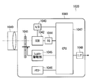
- Imaging mechanism The block diagram of FIG. 2 shows the imaging mechanism 1020.
- the imaging mechanism 1020 includes an imaging lens 1040, a color filter 1041, an imaging sensor 1042, an analog / digital (A / D) converter 1043, a timing generator 1044, a filter driving unit 1045, a memory 1046, and a controller 1047. , An interface 1048 and a housing 1049. Components other than these components may be added to the imaging mechanism 1020.
- the imaging mechanism 1020 does not include a display unit and an operation unit, and is controlled by the PC 1021.
- the imaging lens 1040 guides light to the imaging sensor 1042 via the color filter 1041, and forms an image on the sensor surface of the imaging sensor 1042.
- the color filter 1041 transmits light of any one of the first color, the second color, and the third color.
- the color filter 1041 is an XYZ filter.
- Controller 1047 controls timing generator 1044.
- the timing generator 1044 outputs a driving pulse to the image sensor 1042.
- the imaging sensor 1042 generates an image signal representing an image formed on the sensor surface according to the drive pulse, and outputs the image signal to the A / D converter 1043.
- the A / D converter 1043 converts an analog image signal into digital image data and outputs the digital image data to the controller 1047.
- the controller 1047 writes digital image data into the memory 1046.
- Controller 1047 controls filter drive unit 1045.
- the filter driving unit 1045 switches the color of light transmitted by the color filter 1041.
- the controller 1047 reads the image data of the first color component, the second color component, and the third color component from the memory 1046, generates tristimulus value two-dimensional image data, and outputs the data to the interface 1048.
- the interface 1048 outputs the two-dimensional image data to the PC 1021.
- standard, wide-angle, and telephoto imaging lenses 1040 are prepared, an imaging lens 1040 having an angle of view that can accommodate the entire object to be measured 9000 is selected, and the selected imaging lens 1040 is attached to the housing 1049.
- the imaging sensor 1042 is an area sensor (two-dimensional sensor).
- the imaging sensor 1042 is a charge coupled device (CCD) sensor.
- the image sensor 1042 may be other than a CCD sensor.
- the imaging sensor 1042 may be a complementary metal oxide semiconductor (CMOS) sensor.
- CMOS complementary metal oxide semiconductor
- the controller 1047 is a central processing unit (CPU).
- the controller 1047 is a field programmable gate array (FPGA).
- the controller 1047 may be an application specific integrated circuit (ASIC).
- PC hardware The block diagram in FIG. 3 shows the PC 1021.
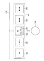
- the PC 1021 includes a CPU 1060, a memory 1061, a hard disk drive 1062, an operation unit 1063, and a display unit 1064. Components other than these components may be added to the PC 1021.
- the hard disk drive 1062 is installed with a program 1080 for processing two-dimensional image data.
- the program 1080 may be provided by the recording medium 1100 or may be provided via the network 1120.
- the program 1080 is loaded into the memory 1061 and the CPU 1060 executes the program 1080.
- the hard disk drive 1062 may be replaced with another type of storage device.
- the hard disk drive 1062 may be replaced with a solid state drive.
- the operation unit 1063 is a keyboard, a pointing device, a switch, a rotary encoder, or the like.
- the pointing device is a mouse, a track pad, a touch panel, a tablet, or the like.
- the display unit 1064 is a display, a lamp, or the like.
- the display is a liquid crystal display, an organic electroluminescence (EL) display, or the like.
- FIG. 4 shows the contents of processing of two-dimensional image data.
- the two-dimensional image data includes an acquisition unit 1140, a display control unit 1141, an identification unit 1142, an area setting unit 1143, a selection unit 1144, a condition setting unit 1145, a processing unit 1146, and an operation unit. 1063 and the display unit 1064.
- the acquisition unit 1140, the display control unit 1141, the identification unit 1142, the region setting unit 1143, the selection unit 1144, the condition setting unit 1145, and the processing unit 1146 are realized by the CPU 1060 executing the program 1080. All or part of the processing of the two-dimensional image data may be performed by dedicated hardware.
- the two-dimensional image data processed by the PC 1021 may be acquired from the imaging mechanism 1020 immediately before processing, or may be acquired in the past and stored in the hard disk drive 1062.
- the PC 1021 can process the two-dimensional image data even when disconnected from the imaging mechanism 1020.
- FIG. 5 shows the contents of the processing of the two-dimensional image data.
- the processing contents of the two-dimensional image data will be described with reference to FIGS. 4 and 5.
- step S101 the acquisition unit 1140 acquires two-dimensional image data from the imaging mechanism 1020.
- step S102 the display control unit 1141 draws a two-dimensional image on the display unit 1064 based on the two-dimensional image data.
- the display control unit 1141 may be omitted.
- step S103 the identification unit 1142 identifies the background area and the measurement object area inside the two-dimensional image.
- the background area is an area where the object to be measured 9000 is not shown.
- the measured object region is a region where the measured object 9000 is shown.
- an area having a relatively high luminance is recognized as the object area to be measured, and an area having a relatively low luminance is recognized as the background area.
- the background area and the measurement object area may be identified by other algorithms. For example, an area having a specific color may be recognized as the measurement object area, and the remaining area may be recognized as the background area.
- a contour having a specific shape may be detected, and the region included in the detected contour may be recognized as the measurement target region, and the remaining region may be recognized as the background region.
- the shape of the measurement object region is a rectangle.
- the rectangle includes a square.
- the shape of the measurement object region may be other than a rectangle.
- the identification unit 1142 detects that an operation for designating the number of object areas to be measured has been performed using the operation unit 1063, and recognizes the object area to be measured designated by the operation. Thereby, the background area and the measurement object area are identified at high speed.
- the number of measurement object regions may be specified by being divided into rows m and columns n, for example, (m ⁇ n).
- the identification unit 1142 recognizes in advance that the m objects 9000 are arranged in n rows, so that the object 9000 can be easily detected.
- the identification unit 1142 draws information for identifying the background region and the measurement target region on the display unit 1064.
- step S104 the region setting unit 1143 sets two or more processed regions in a two-dimensional image.
- the processed area is an area specified as a processing target in the measured object area in the two-dimensional image, and one processed area corresponds to one display screen that is the measured object.
- the region setting unit 1143 sets the processing target region in the measurement target region. Thereby, a to-be-processed area
- the region setting unit 1143 indicates that the operation for setting the processing region has been performed using the operation unit 1063.
- the detected area is set according to the detected operation.
- step S105 the selection unit 1144 selects one or more processing areas from two or more processing areas. First, in the first selection, a processing area is selected while leaving at least one non-processing area to be selected.
- the selection unit 1144 selects information for identifying one or more selected processing areas (selected processing areas) and one or more selected processing areas (non-selecting processing areas). Drawing on the display unit 1064. Thereby, the selected process area and the non-selection process area are easily recognized.
- the selection unit 1144 detects that an operation for selecting one or more processed regions has been performed using the operation unit 1063, and selects one or more processed regions according to the operation.
- One or more processed areas may be selected without detecting an operation using the operation unit 1063.
- the processing areas may be selected one by one from two or more processing areas.
- nine processing areas divided into 3 ⁇ 3 may be set in advance, and individual processing may be executed on the processing areas selected in order or arbitrarily.
- step S106 the condition setting unit 1145 sets a first processing condition to be applied to the selected processing target area.
- step S107 the process branches depending on whether the setting is completed. If the setting has not been completed, the process returns to step S105.
- step S105 the one or more process areas (the first one or more process areas) that have been selected by the selection unit 1144 are defined. A different new one or more process target areas (second one or more process target areas) are selected, and in step S106, the condition setting unit 1145 is applied to the second one or more process target areas. 2 processing conditions are set. The second processing condition is different from the first processing condition. Accordingly, the first processing condition applied to the first one or more processed areas and the second processing condition applied to the second one or more processed areas are set independently of each other. . Even if the second processing condition is set, the first processing condition is not affected.
- the second processing condition may or may not be the same for all of the second one or more processed areas. If the setting has been completed, the process proceeds to step S108. From the branch of the process in step S107, steps S105 and S106 are repeatedly executed as necessary until the setting is completed.
- the condition setting unit 1145 uses chromaticity data or luminance applied to the first one or more processed areas.
- the first lower limit value and the first upper limit value of the data and the second lower limit value and the second upper limit value of the chromaticity data or luminance data applied to the second one or more processed regions are independent of each other. And set. Thereby, the mapping range of the chromaticity data or the luminance data to the pseudo color scale is set for each measurement object 9000.
- the condition setting unit 1145 includes the position of the first spot applied to the first one or more processed areas.
- the position of the second spot applied to the second one or more processed areas is set independently of each other. Thereby, the extraction position of chromaticity data or luminance data is set for each measurement object 9000.
- the condition setting unit 1145 sets the first unevenness enhancement condition and the second unevenness applied to the first one or more processed areas. And the second non-uniform emphasis condition applied to one or more of the regions to be processed. As a result, an uneven enhancement condition of chromaticity data or luminance data is set for each object 9000 to be measured.
- the condition setting unit 1145 draws a user interface for setting processing conditions to be applied to the selected processing target area along with the two-dimensional image on the display unit 1064.
- the condition setting unit 1145 detects that an operation for setting a processing condition to be set in the selected processing region is performed on the user interface using the operation unit 1063, and the processing target selected according to the operation Set the processing conditions to be applied to the area.
- the user interface is a graphical user interface (GUI) component.
- GUI graphical user interface
- the GUI component is, for example, a slide bar, a text box, a radio button, or the like.
- step S ⁇ b> 108 the processing unit 1146 applies the first processing condition applied to the first one or more processing regions, and the chromaticity data and the luminance data in the first one or more processing regions. Both or one is acquired from the two-dimensional image data and processed.
- the processing unit 1146 applies the second processing condition that is applied to the second one or more processed areas, and outputs both or one of the chromaticity data and the luminance data in the second one or more processed areas. Obtain and process from 2D image data.
- the processing unit 1146 performs processing from the first lower limit value to the first upper limit value of chromaticity data or luminance data.
- the range is mapped to a pseudo color scale, the chromaticity data or luminance data in the first one or more processed areas is acquired from the two-dimensional image data, and the chromaticity or luminance in the first one or more processed areas is acquired.
- the two-dimensional distribution pseudo color display is drawn on the display unit 1064.
- the processing unit 1146 maps the range from the second lower limit value to the second upper limit value of the chromaticity data or the luminance data on the pseudo color scale, and the chromaticity data in the second one or more processed areas.
- the luminance data is acquired from the two-dimensional image data, and a pseudo color display of a two-dimensional distribution of chromaticity or luminance in the second one or more processed areas is drawn on the display unit 1064.
- pseudo color display the position of interest is colored with a color associated with chromaticity data or luminance data at the position of interest.
- the processing unit 1146 displays the chromaticity data at the first spot position in the first one or more processed areas, Luminance data is acquired from the two-dimensional image data, and the chromaticity or luminance value at the position of the first spot in the first one or more processed areas is drawn on the display unit 1064.
- the processing unit 1146 acquires chromaticity data or luminance data at the position of the second spot of the second one or more processed areas from the two-dimensional image data, and the second one or more processed areas The chromaticity or luminance value at the position of the second spot is drawn on the display unit 1064.
- the processing unit 1146 acquires chromaticity data or luminance data in the first one or more processed areas from the two-dimensional image data. Then, the display unit 1064 draws a highlighted display of chromaticity and luminance unevenness in the processing region selected according to the first unevenness enhancement condition. In addition, the processing unit 1146 acquires chromaticity data or luminance data in the second one or more processed areas from the two-dimensional image data, and the second one or more processed areas according to the second unevenness enhancement condition. The display unit 1064 draws a highlighted display of the chromaticity and luminance unevenness.
- the two-dimensional color luminance meter 1000 it becomes easy to individually evaluate each of two or more objects to be measured 9000 that are simultaneously imaged.
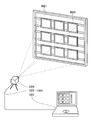
- FIG. 6 shows a usage example of the two-dimensional color luminance meter 1000.
- nine liquid crystal panels 9020 are supported and arranged on a frame 9021.
- the number of arrangements in the vertical direction is 3, and the number of arrangements in the horizontal direction is 3. All or part of the number of liquid crystal panels 9020, the number of arrangement in the vertical direction, and the number of arrangement in the horizontal direction may be changed.
- An imaging mechanism 1020 is installed apart from the nine arranged liquid crystal panels 9020, and two-dimensional image data representing a two-dimensional image showing the nine liquid crystal panels 9020 is generated.
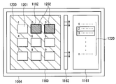
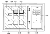
- an image drawing field 1160, a text drawing field 1161, and a slide bar 1162 are drawn on the display unit 1064.
- the slide bar 1162 may be replaced with other types of GUI parts.
- the acquisition unit 1140 acquires image data representing a two-dimensional image in which nine liquid crystal panels 9020 are captured (two-dimensional image data), as shown in FIG. 7, the display control unit 1141 displays nine liquid crystals.
- a two-dimensional image 1180 showing the panel 9020 is drawn in the image drawing field 1160.
- the identification unit 1142 identifies the background area 1200 and the measurement object area 1201, and as illustrated in FIG. 8, the frame 1181 indicating the outlines of the nine measurement object areas 1201 is superimposed on the two-dimensional image 1180 to draw an image. Draw in column 1160. A frame 1181 also shows the outline of the processing area.
- the processing unit 1146 renders a pseudo color display of a two-dimensional distribution of chromaticity or luminance within the frame 1181 after the processing region is set. The processing unit 1146 may draw a highlighted display of unevenness in chromaticity or luminance inside the frame 1181.
- the selection unit 1144 selects two process areas 1202 from the nine measurement object areas 1201, a thick frame 1182 indicating the outline of the selected process area 1202 is selected as shown in FIG.
- the part 1144 draws in the image drawing field 1160.
- the selection unit 1144 draws a list 1220 of nine measurement object regions 1201 in the text drawing field 1161.
- the selected processing area 1202 is displayed in reverse video.
- the selected target area 1202 and the non-selected target area 1203 are identified. Numbers are assigned to the nine measured object regions 1201. The number is drawn in the image drawing field 1160 so as to overlap the two-dimensional image 1180.
- the processing unit 1146 draws the chromaticity or luminance value 1221 at the spot position in the processing target area 1202 in the list 1220 of the measuring target area 1201.
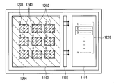
- the condition setting unit 1145 detects the operation. According to the operation, the first lower limit value and the first upper limit value of chromaticity data or luminance data are set.
- the processing unit 1146 redraws the pseudo color display of the two-dimensional distribution of chromaticity or luminance in the processing target area 1202 selected by applying the set first lower limit value and first upper limit value.
- the processing unit 1146 applies chromaticity or luminance at the position of the first spot in the processing target area 1202 selected by applying the set position of the first spot. Redraw the value of.
- a circle 1240 indicating the position of the spot is drawn inside the processing area 1201.
Landscapes
- Physics & Mathematics (AREA)
- Spectroscopy & Molecular Physics (AREA)
- General Physics & Mathematics (AREA)
- Engineering & Computer Science (AREA)
- Computer Hardware Design (AREA)
- Theoretical Computer Science (AREA)
- Spectrometry And Color Measurement (AREA)
- Image Processing (AREA)
- Testing Of Optical Devices Or Fibers (AREA)
Abstract
Description
図1の模式図は、2次元色彩輝度計1000の望ましい実施の形態を示す。
図2のブロック図は、撮像機構1020を示す。
図3のブロック図は、PC1021を示す。
図4のブロック図は、2次元画像データの処理の内容を示す。
図6の模式図は、2次元色彩輝度計1000の使用例を示す。
図7から図11までの模式図は、表示部1064の表示例を示す。
1020 撮像機構
1021 PC
1160 画像描画欄
1161 テキスト描画欄
1162 スライドバー
Claims (12)
- 2次元画像を表現する画像データを取得する取得部と、
2個以上の被処理領域を前記2次元画像に設定する領域設定部と、
前記2個以上の被処理領域から、少なくとも1個の被処理領域を選択せずに残して、第1の1個以上の被処理領域を選択する選択部と、
選択された前記第1の1個以上の被処理領域に適用される第1の処理条件を設定する条件設定部と、
前記第1の処理条件を適用して前記第1の1個以上の被処理領域における色彩データ及び輝度データの両方又は片方を前記画像データから取得し処理する処理部と、
を備える2次元画像データ処理装置。 - 前記条件設定部は、
前記第1の1個以上の被処理領域とは異なる第2の1個以上の被処理領域に適用され前記第1の処理条件と異なる第2の処理条件を設定し、
前記処理部は、
第2の処理条件を適用して前記第2の1個以上の被処理領域における色彩データ及び輝度データの両方又は片方を前記画像データから取得し処理する
請求項1の2次元画像データ処理装置。 - 表示部
をさらに備え、
前記条件設定部は、
前記第1の1個以上の被処理領域に適用される前記色彩データ又は前記輝度データの上限値及び下限値を前記第1の処理条件として設定し、
前記処理部は、
前記色彩データ又は前記輝度データの前記下限値から前記上限値までの範囲を擬似カラースケールにマッピングし、前記第1の1個以上の被処理領域における前記色彩データ又は前記輝度データを前記画像データから取得し、前記第1の1個以上の被処理領域における色彩又は輝度の2次元分布の擬似カラー表示を前記表示部に描画する
請求項1の2次元画像データ処理装置。 - 表示部
をさらに備え、
前記条件設定部は、
前記第1の1個以上の被処理領域に適用されるスポットの位置を前記第1の処理条件として設定し、
前記処理部は、
前記第1の1個以上の被処理領域の前記スポットの位置における前記色彩データ又は前記輝度データを前記画像データから取得し、前記第1の1個以上の被処理領域の前記スポットの位置における色彩又は輝度の値を前記表示部に描画する
請求項1の2次元画像データ処理装置。 - 表示部
をさらに備え、
前記条件設定部は、
前記第1の1個以上の被処理領域に適用されるむらの強調条件を前記第1の処理条件として設定し、
前記処理部は、
前記第1の1個以上の被処理領域における前記色彩データ又は前記輝度データを前記画像データから取得し、前記むらの強調条件に従って前記第1の1個以上の被処理領域における色彩又は輝度のむらの強調表示を前記表示部に描画する
請求項1の2次元画像データ処理装置。 - 表示部と、
前記画像データに基づいて前記2次元画像を前記表示部に描画する表示制御部と、
をさらに備え、
前記選択部は、
前記第1の1個以上の被処理領域及び前記第1の1個以上の被処理領域以外を識別する情報を前記表示部に描画する
請求項1の2次元画像データ処理装置。 - 表示部と、
操作部と、
前記画像データに基づいて前記2次元画像を前記表示部に描画する表示制御部と、
をさらに備え、
前記条件設定部は、
前記第1の処理条件を設定するためのユーザーインターフェースを前記2次元画像と並べて前記表示部に描画し、前記第1の処理条件を設定する操作が前記操作部を用いて前記ユーザーインターフェースに対して行われたことを検出し、前記操作に従って前記第1の処理条件を設定する
請求項1の2次元画像データ処理装置。 - 前記2次元画像の内部の背景領域及び被計測物領域を識別する識別部
をさらに備え、
前記領域設定部は、
前記被計測物領域に前記被処理領域を設定する
請求項1の2次元画像データ処理装置。 - 操作部
をさらに備え、
前記識別部は、
前記被計測物領域の数を指定する操作が前記操作部を用いて行われたことを検出し、前記操作により指定された数の前記被計測物領域を認識する
請求項8の2次元画像データ処理装置。 - 撮像を行い、撮像された2次元画像を表現する画像データを生成する撮像機構と、
前記画像データを取得する取得部と、
2個以上の被処理領域を前記撮像された2次元画像に設定する領域設定部と、
前記2個以上の被処理領域から、少なくとも1個の被処理領域を選択せずに残して、1個以上の被処理領域を選択する選択部と、
選択された前記1個以上の被処理領域に適用される処理条件を設定する条件設定部と、
前記処理条件を適用して前記1個以上の被処理領域における色彩データ又は輝度データの両方又は片方を前記画像データから取得し処理する処理部と、
を備える2次元色彩輝度計。 - a) 2次元画像を表現する画像データを取得する工程と、
b) 2個以上の被処理領域を前記2次元画像に設定する工程と、
c) 前記2個以上の被処理領域から、少なくとも1個の被処理領域を選択せずに残して、1個以上の被処理領域を選択する工程と、
d) 選択された前記1個以上の被処理領域に適用される処理条件を設定する工程と、
e) 前記処理条件を適用して前記1個以上の被処理領域における色彩データ及び輝度データの両方又は片方を前記画像データから取得し処理する工程と、
を備える2次元画像データ処理方法。 - a) 2次元画像を表現する画像データを取得する工程と、
b) 2個以上の被処理領域を前記2次元画像に設定する工程と、
c) 前記2個以上の被処理領域から、少なくとも1個の被処理領域を選択せずに残して、1個以上の被処理領域を選択する工程と、
d) 選択された前記1個以上の被処理領域に適用される処理条件を設定する工程と、
e) 前記処理条件を適用して前記1個以上の被処理領域における色彩データ及び輝度データの両方又は片方を前記画像データから取得し処理する工程と、
をコンピューターに実行させる2次元画像データ処理プログラム。
Priority Applications (3)
| Application Number | Priority Date | Filing Date | Title |
|---|---|---|---|
| CN201380055816.8A CN104769398B (zh) | 2012-10-25 | 2013-10-09 | 二维图像数据处理装置、二维色彩亮度计、以及二维图像数据处理方法 |
| JP2014543222A JP6015766B2 (ja) | 2012-10-25 | 2013-10-09 | 2次元画像データ処理装置、2次元色彩輝度計、2次元画像データ処理方法及び2次元画像データ処理プログラム |
| KR1020157009945A KR101808393B1 (ko) | 2012-10-25 | 2013-10-09 | 2차원 화상 데이터 처리 장치, 2차원 색채 휘도계, 2차원 화상 데이터 처리 방법 및 컴퓨터 판독가능한 기록매체 |
Applications Claiming Priority (2)
| Application Number | Priority Date | Filing Date | Title |
|---|---|---|---|
| JP2012-235302 | 2012-10-25 | ||
| JP2012235302 | 2012-10-25 |
Publications (1)
| Publication Number | Publication Date |
|---|---|
| WO2014065121A1 true WO2014065121A1 (ja) | 2014-05-01 |
Family
ID=50544501
Family Applications (1)
| Application Number | Title | Priority Date | Filing Date |
|---|---|---|---|
| PCT/JP2013/077481 Ceased WO2014065121A1 (ja) | 2012-10-25 | 2013-10-09 | 2次元画像データ処理装置、2次元色彩輝度計、2次元画像データ処理方法及び2次元画像データ処理プログラム |
Country Status (4)
| Country | Link |
|---|---|
| JP (1) | JP6015766B2 (ja) |
| KR (1) | KR101808393B1 (ja) |
| CN (1) | CN104769398B (ja) |
| WO (1) | WO2014065121A1 (ja) |
Cited By (3)
| Publication number | Priority date | Publication date | Assignee | Title |
|---|---|---|---|---|
| JP2016042667A (ja) * | 2014-08-18 | 2016-03-31 | 国立大学法人 東京大学 | 画像表示方法、画像表示プログラム、画像表示装置、および画像表示物 |
| WO2017051909A1 (ja) * | 2015-09-25 | 2017-03-30 | 株式会社ニコン | 画像処理装置、画像処理プログラム、撮像装置、および撮像プログラム |
| JP2019080325A (ja) * | 2018-12-19 | 2019-05-23 | 国立大学法人 東京大学 | 画像表示方法、画像表示プログラム、および画像表示装置 |
Families Citing this family (1)
| Publication number | Priority date | Publication date | Assignee | Title |
|---|---|---|---|---|
| WO2018012478A1 (ja) * | 2016-07-15 | 2018-01-18 | コニカミノルタ株式会社 | 測色計 |
Citations (3)
| Publication number | Priority date | Publication date | Assignee | Title |
|---|---|---|---|---|
| JPH05332838A (ja) * | 1992-05-26 | 1993-12-17 | Imaizumi Shokai:Kk | 色ムラ外観検査装置 |
| JP2008233107A (ja) * | 2008-06-16 | 2008-10-02 | Matsushita Electric Works Ltd | 外観検査方法及び外観検査装置 |
| JP2011158421A (ja) * | 2010-02-03 | 2011-08-18 | Toppan Printing Co Ltd | 印刷物検査装置 |
Family Cites Families (4)
| Publication number | Priority date | Publication date | Assignee | Title |
|---|---|---|---|---|
| KR20030013933A (ko) * | 2001-08-10 | 2003-02-15 | 엘지.필립스 엘시디 주식회사 | 액정표시패널의 구동방법 |
| JP2005233788A (ja) * | 2004-02-19 | 2005-09-02 | Sony Corp | 検査装置および検査方法 |
| CN1842166A (zh) * | 2005-03-29 | 2006-10-04 | 统宝光电股份有限公司 | 显示影像的方法 |
| KR101152064B1 (ko) * | 2005-11-02 | 2012-06-11 | 엘지디스플레이 주식회사 | 화상 구현 장치 및 그 구동방법 |
-
2013
- 2013-10-09 CN CN201380055816.8A patent/CN104769398B/zh active Active
- 2013-10-09 KR KR1020157009945A patent/KR101808393B1/ko not_active Expired - Fee Related
- 2013-10-09 JP JP2014543222A patent/JP6015766B2/ja active Active
- 2013-10-09 WO PCT/JP2013/077481 patent/WO2014065121A1/ja not_active Ceased
Patent Citations (3)
| Publication number | Priority date | Publication date | Assignee | Title |
|---|---|---|---|---|
| JPH05332838A (ja) * | 1992-05-26 | 1993-12-17 | Imaizumi Shokai:Kk | 色ムラ外観検査装置 |
| JP2008233107A (ja) * | 2008-06-16 | 2008-10-02 | Matsushita Electric Works Ltd | 外観検査方法及び外観検査装置 |
| JP2011158421A (ja) * | 2010-02-03 | 2011-08-18 | Toppan Printing Co Ltd | 印刷物検査装置 |
Cited By (4)
| Publication number | Priority date | Publication date | Assignee | Title |
|---|---|---|---|---|
| JP2016042667A (ja) * | 2014-08-18 | 2016-03-31 | 国立大学法人 東京大学 | 画像表示方法、画像表示プログラム、画像表示装置、および画像表示物 |
| WO2017051909A1 (ja) * | 2015-09-25 | 2017-03-30 | 株式会社ニコン | 画像処理装置、画像処理プログラム、撮像装置、および撮像プログラム |
| JPWO2017051909A1 (ja) * | 2015-09-25 | 2018-06-14 | 株式会社ニコン | 画像処理装置、画像処理プログラム、撮像装置、および撮像プログラム |
| JP2019080325A (ja) * | 2018-12-19 | 2019-05-23 | 国立大学法人 東京大学 | 画像表示方法、画像表示プログラム、および画像表示装置 |
Also Published As
| Publication number | Publication date |
|---|---|
| CN104769398B (zh) | 2017-10-24 |
| JP6015766B2 (ja) | 2016-10-26 |
| JPWO2014065121A1 (ja) | 2016-09-08 |
| KR101808393B1 (ko) | 2017-12-12 |
| CN104769398A (zh) | 2015-07-08 |
| KR20150058417A (ko) | 2015-05-28 |
Similar Documents
| Publication | Publication Date | Title |
|---|---|---|
| US11733032B2 (en) | Measurement device and measurement method | |
| US10089787B2 (en) | Systems and methods for displaying infrared images | |
| EP3783885B1 (en) | Image display device and image display method | |
| US9292925B2 (en) | Imaging system and control method thereof | |
| JP6619194B2 (ja) | タッチパネル検査装置及び方法 | |
| US10033945B2 (en) | Orientation-adapted image remote inspection systems and methods | |
| JP6015766B2 (ja) | 2次元画像データ処理装置、2次元色彩輝度計、2次元画像データ処理方法及び2次元画像データ処理プログラム | |
| JP2015112429A5 (ja) | ||
| JPWO2009088053A1 (ja) | 測定装置および方法、並びに、プログラム | |
| JP5156972B2 (ja) | 位置測定装置及び位置測定方法 | |
| WO2015035744A1 (zh) | 一种图像处理方法 | |
| CN104752445A (zh) | 交互式电子装置及其像素单元 | |
| JP2009296127A5 (ja) | ||
| US8624580B2 (en) | Configurable measuring device with display and corresponding methods | |
| US11321811B2 (en) | Imaging apparatus and driving method of the same | |
| WO2015137019A1 (ja) | 温度監視装置、及び、温度監視方法 | |
| JP2017040520A5 (ja) | ||
| US11902672B2 (en) | Flicker measurement device, flicker measurement method, flicker measurement program, flicker evaluation assistance device, flicker evaluation assistance method, and flicker evaluation assistance program | |
| KR20140025725A (ko) | 이미지 센서 및 그를 갖는 카메라 장치 | |
| JP4598501B2 (ja) | 温度測定表示装置 | |
| JP2017107052A (ja) | 表示システム、表示装置測定方法、表示装置測定プログラムならびに表示装置 | |
| JP6319964B2 (ja) | 測定装置 | |
| JP2015045758A5 (ja) | ||
| KR20120108497A (ko) | 비전 검사 장치 및 방법 | |
| JP7070568B2 (ja) | 二次元測色装置および二次元測色方法 |
Legal Events
| Date | Code | Title | Description |
|---|---|---|---|
| 121 | Ep: the epo has been informed by wipo that ep was designated in this application |
Ref document number: 13848839 Country of ref document: EP Kind code of ref document: A1 |
|
| ENP | Entry into the national phase |
Ref document number: 2014543222 Country of ref document: JP Kind code of ref document: A |
|
| ENP | Entry into the national phase |
Ref document number: 20157009945 Country of ref document: KR Kind code of ref document: A |
|
| NENP | Non-entry into the national phase |
Ref country code: DE |
|
| 122 | Ep: pct application non-entry in european phase |
Ref document number: 13848839 Country of ref document: EP Kind code of ref document: A1 |