WO2014065069A1 - Saw blade - Google Patents

Saw blade Download PDF

Info

Publication number
WO2014065069A1
WO2014065069A1 PCT/JP2013/075878 JP2013075878W WO2014065069A1 WO 2014065069 A1 WO2014065069 A1 WO 2014065069A1 JP 2013075878 W JP2013075878 W JP 2013075878W WO 2014065069 A1 WO2014065069 A1 WO 2014065069A1
Authority
WO
WIPO (PCT)
Prior art keywords
tip
chip
long
chips
workpiece
Prior art date
Application number
PCT/JP2013/075878
Other languages
French (fr)
Japanese (ja)
Inventor
西尾 悟
Original Assignee
兼房株式会社
Priority date (The priority date is an assumption and is not a legal conclusion. Google has not performed a legal analysis and makes no representation as to the accuracy of the date listed.)
Filing date
Publication date
Application filed by 兼房株式会社 filed Critical 兼房株式会社
Priority to US14/437,657 priority Critical patent/US20150251259A1/en
Priority to EP13849853.0A priority patent/EP2910327A4/en
Priority to JP2014543204A priority patent/JP5951788B2/en
Publication of WO2014065069A1 publication Critical patent/WO2014065069A1/en

Links

Images

Classifications

    • BPERFORMING OPERATIONS; TRANSPORTING
    • B23MACHINE TOOLS; METAL-WORKING NOT OTHERWISE PROVIDED FOR
    • B23DPLANING; SLOTTING; SHEARING; BROACHING; SAWING; FILING; SCRAPING; LIKE OPERATIONS FOR WORKING METAL BY REMOVING MATERIAL, NOT OTHERWISE PROVIDED FOR
    • B23D61/00Tools for sawing machines or sawing devices; Clamping devices for these tools
    • B23D61/02Circular saw blades
    • B23D61/021Types of set; Variable teeth, e.g. variable in height or gullet depth: Varying pitch; Details of gullet
    • BPERFORMING OPERATIONS; TRANSPORTING
    • B23MACHINE TOOLS; METAL-WORKING NOT OTHERWISE PROVIDED FOR
    • B23DPLANING; SLOTTING; SHEARING; BROACHING; SAWING; FILING; SCRAPING; LIKE OPERATIONS FOR WORKING METAL BY REMOVING MATERIAL, NOT OTHERWISE PROVIDED FOR
    • B23D61/00Tools for sawing machines or sawing devices; Clamping devices for these tools
    • B23D61/02Circular saw blades
    • B23D61/028Circular saw blades of special material
    • BPERFORMING OPERATIONS; TRANSPORTING
    • B23MACHINE TOOLS; METAL-WORKING NOT OTHERWISE PROVIDED FOR
    • B23DPLANING; SLOTTING; SHEARING; BROACHING; SAWING; FILING; SCRAPING; LIKE OPERATIONS FOR WORKING METAL BY REMOVING MATERIAL, NOT OTHERWISE PROVIDED FOR
    • B23D61/00Tools for sawing machines or sawing devices; Clamping devices for these tools
    • B23D61/02Circular saw blades
    • B23D61/04Circular saw blades with inserted saw teeth the teeth being individually inserted
    • YGENERAL TAGGING OF NEW TECHNOLOGICAL DEVELOPMENTS; GENERAL TAGGING OF CROSS-SECTIONAL TECHNOLOGIES SPANNING OVER SEVERAL SECTIONS OF THE IPC; TECHNICAL SUBJECTS COVERED BY FORMER USPC CROSS-REFERENCE ART COLLECTIONS [XRACs] AND DIGESTS
    • Y10TECHNICAL SUBJECTS COVERED BY FORMER USPC
    • Y10TTECHNICAL SUBJECTS COVERED BY FORMER US CLASSIFICATION
    • Y10T83/00Cutting
    • Y10T83/929Tool or tool with support
    • Y10T83/9319Toothed blade or tooth therefor
    • Y10T83/935Plural tooth groups

Definitions

  • the present invention relates to a chip saw for cutting and grooving workpieces such as wood, wood board, resin, ceramic materials, metals, and composite materials thereof.
  • the tip saw has a base metal and a plurality of chips attached to the outer periphery of the base metal.
  • the chip is formed of cemented carbide, polycrystalline diamond, CBN, cermet, ceramic, or a material coated thereon.
  • the chip is provided on the base metal so as to have a lead angle and a sharpening angle suitable for the workpiece.
  • the tip saw is mounted on a processing apparatus and rotated to process a workpiece.
  • the amount of waviness on the cut surface of the workpiece depends on various factors. For example, various angles such as clam angle, chip deflection during processing, base metal rigidity, and the like are factors.
  • Japanese Patent No. 3170498 discloses a chip having a special side shape that reduces the surface roughness of a cut surface of a workpiece.
  • the tip saw is attached to the flange of the processing equipment.
  • the processing apparatus rotates the tip saw, the flange contact surface or the rotating shaft with which the tip saw contacts may swing.
  • the waviness of the cut surface of the workpiece may increase due to the deflection.
  • the side surface of the chip largely shakes at a rate of once per rotation due to the shake of the rotating shaft or the flange contact surface.
  • the tip saw has a base metal and a plurality of chips provided on the outer periphery of the base metal.
  • the plurality of chips include a long chip having a radial set line length of 4 mm or more and a short chip having a radial set line length of less than 4 mm.
  • the number of long chips is 2 to 15% of the total number of long chips and short chips, and two or more.
  • the tip saw is attached to a rotating shaft of the processing apparatus and a flange provided on the rotating shaft.
  • the side surface of the tip saw swings.
  • the tip saw can sufficiently reduce the amount of waviness of the cut surface of the workpiece even in such a case.
  • the tip saw can be constructed at low cost.
  • the chip is made of an expensive material such as cemented carbide or polycrystalline diamond. Therefore, long chips are very expensive compared to short chips. However, since the number of long chips is very small, 2 to 15% of the total number of chips, the chip saw can be constructed at low cost.
  • the tip saw can sufficiently reduce the waviness of the cut surface of the workpiece and can be constructed at low cost.
  • FIG. 2 is a partially enlarged front view of II in FIG. 1.
  • FIG. 3 is a cross-sectional view taken along line III-III in FIG. 1. It is an expanded sectional view of IV of FIG.
  • FIG. 5 is a cross-sectional view taken along line VV in FIG. 1. It is an expanded sectional view of VI of FIG.
  • It is a schematic diagram which processes a workpiece with the tip saw of this invention. It is the schematic diagram which showed the relationship between the blade edge side run-out width and the waviness of a cut surface in VIII of FIG. FIG.
  • FIG. 6 is a relationship diagram between the feed speed of the workpiece and the amount of waviness of the cut surface when the workpiece is machined with a tip saw having a long tip with a clam angle of 1 ° and each set wire length.
  • FIG. 5 is a relationship diagram between the feed speed of a workpiece and the amount of waviness of the cut surface when the workpiece is machined with a tip saw having a long tip with a clam angle of 0.5 ° and each set wire length. It is a related figure of the amount of waviness of a blade edge side run width and a cut surface at the time of processing a work material with a tip saw. It is a modification of FIG. It is a modification of FIG. It is an expanded sectional view near the 1st short chip of other modifications. It is an expanded sectional view near the 2nd short chip of other modifications. It is an expanded sectional view near the long chip of another modification.
  • the tip saw 10 has a disk shape like a circular saw or a side milling cutter.
  • the chip saw 10 includes a base metal (saw body) 12 and a plurality of chips 14 provided on the outer periphery of the base metal 12.
  • the base metal 12 has a disk shape.
  • a circular fitting hole 16 penetrating in the axial direction is formed in the center of the base metal 12.
  • the base metal thickness U1 of the base metal 12 is determined in view of the bending rigidity. When the outer diameter D1 of the base metal 12 is 400 mm, the base metal thickness U1 is 2.5 to 8 mm, for example, 3.2 mm.
  • the tip saw 10 has a plurality of blade mounting portions 20 on the outer periphery of the base metal 12 as shown in FIG.
  • the plurality of blade mounting portions 20 are arranged, for example, at equal central angle intervals.
  • the blade mounting portion 20 protrudes from the base metal 12 in the radial direction and has a substantially mountain shape.
  • the blade mounting portion 20 has a vertex portion 22 at the outermost radial direction.
  • the apex portion 22 is located at the tip of the outer peripheral edge of the blade mounting portion 20 in the rotational direction Fn.
  • the blade mounting portion 20 has a blade mounting surface 24 and an outer peripheral inclined surface 26 as shown in FIG.
  • the blade mounting surface 24 extends radially inward from the apex portion 22 and is positioned on the rotational direction Fn side with respect to the outer peripheral inclined surface 26.
  • the outer peripheral inclined surface 26 extends from the apex portion 22 in the direction opposite to the rotation direction Fn, and forms the outer peripheral edge of the blade mounting portion 20.
  • the outer peripheral inclined surface 26 has a first outer peripheral inclined surface 26a and a second outer peripheral inclined surface 26b.
  • the first outer peripheral inclined surface 26a extends from the apex portion 22 in a direction opposite to the rotational direction Fn and radially inward.
  • the second outer peripheral inclined surface 26b extends radially inward from the first outer peripheral inclined surface 26a at a larger inclination angle than the first outer peripheral inclined surface 26a.
  • an arcuate surface 28 is formed between the second outer peripheral inclined surface 26 b and the blade mounting surface 24.
  • the circular arc surface 28 is recessed inward in the radial direction between the blade attachment portions 20 to form a galette 29.
  • a stepped shelf on which the tip 14 can be seated is formed between the arc surface 28 and the blade mounting surface 24.
  • the base metal 12 may be formed with a slit (not shown) penetrating in the thickness direction.
  • the base metal 12 may be formed with a slit (not shown) that extends radially inward from the galette 29 or another slit.
  • the base metal 12 is first cut out from the steel plate with, for example, a laser. Next, the blade mounting surface 24 and the like are cut with a milling cutter or the like.
  • the tip 14 is fixed to the blade mounting surface 24 with a brazing material or the like.
  • the chip 14 has a rectangular shape and is a hard chip made of a hard material such as cemented carbide or cermet.
  • the tip 14 is a high hardness tip made of a high hardness sintered body such as polycrystalline diamond.
  • the chip 14 includes a long chip 30 having a relatively long clam line and a short chip 40 having a relatively short clam line.
  • the long chip 30 has a rake face 32, a side face 34, and an outer peripheral flank face 38 as shown in FIGS.
  • the rake face 32 faces the rotation direction Fn and faces the outer peripheral inclined face 26.
  • the side surface 34 is substantially orthogonal to the rake surface 32 and is substantially parallel to the surface of the base metal 12.
  • a side cutting edge 36 is formed at a portion where the rake face 32 and the side face 34 intersect.
  • the outer peripheral flank 38 extends at an acute angle with respect to the rake face 32 and faces radially outward.
  • An outer peripheral cutting edge 39 is formed at a portion where the rake face 32 and the outer peripheral flank 38 intersect.
  • the tip of the long tip 30 protrudes radially outward from the base metal 12 as shown in FIGS.
  • the long chip 30 slightly protrudes in the thickness direction (axial direction) of the base metal 12.
  • the blade thickness T1 of the long tip 30 is 2.6 to 10 mm. For example, when the outer diameter D1 is 400 mm, the blade thickness T1 is 4.4 mm.
  • the short chip 40 is basically configured similarly to the long chip 30. As shown in FIGS. 2, 5 and 6, it has a rake face 42, a side face 44, a side face cutting edge 46, an outer peripheral flank face 48, and an outer peripheral cutting edge 49.
  • the blade thickness T2 of the short tip 40 is 2.6 to 10 mm, for example, 4.4 mm when the outer diameter D1 is 400 mm.
  • the long chip 30 has a set angle R1, a set amount S1, and a set line length L1.
  • the side surfaces 34 are inclined from both axial ends of the outer peripheral cutting edge 39 toward the thickness center.
  • the set angle R1 is an angle of the side surface 34 and the radial line J1 in the thickness direction.
  • the set angle R1 is an angle at which the side surface 34 is directed radially inward from both axial ends of the outer peripheral cutting edge 39.
  • the radial line J1 extends in the radial direction from the outer edge of the outer peripheral cutting edge 39 or the rake face 32 in the thickness direction.
  • the radius line J1 extends from the axial end edge of the outer peripheral cutting edge 39 in the virtual plane H1 and is orthogonal to the center axis C of the tip saw 10.
  • the virtual plane H ⁇ b> 1 is a surface including the outer peripheral cutting edge 39 (the distal end of the long tip 30 in the radial direction) and the center axis C of the tip saw 10.
  • the set amount S1 is the distance in the thickness direction between the outer edge of the outer peripheral cutting edge 39 or the rake face 32 in the thickness direction and the surface of the base metal 12.
  • the clam line length L1 is, for example, the radial length of the outer edge and the inner edge of the rake face 32 in the thickness direction.
  • the clam line length L1 is the radial length of the side surface 34 with respect to the radial line J1.
  • the clam wire length L1 of the long tip 30 is 4 mm or more, preferably 4 to 12 mm.
  • the set wire length L1 of the long tip 30 is less than 4 mm, it is difficult to reduce the amount of undulation of the cut surface of the workpiece W during processing.
  • the set wire length L1 is 12 mm or more, it is difficult to make the tip saw 10 inexpensive.
  • the set wire length L1 is more preferably 4 to 8 mm.
  • the set angle R1 of the long chip 30 is 0 ° to 1.0 ° as shown in FIG.
  • the undulation X of the processed cross section shown in FIG. 8 occurs.
  • the set angle R1 of the long tip 30 is less than 0 ° (that is, a negative set angle)
  • the cutting resistance is increased by the undulation X or the tip 14 is burnt.
  • the set angle R1 of the long tip 30 is larger than 1.0 °, a region where the undulation X and the side surface 34 are in contact with each other is small. This raises a concern that the amount of waviness of the cut surface of the workpiece W cannot be reduced.
  • the set angle R1 of the long tip 30 is preferably 0.2 ° to 0.8 °, and more preferably 0.3 ° to 0.7 °.
  • the set angle R1 of the long chip 30 is preferably the same as the set angle R2 of the short chip 40 from the viewpoint of ease of manufacture.
  • the short chip 40 has a set angle R2, a set amount S2, and a set line length L2, as shown in FIG.
  • the set angle R2 is an angle between the side surface 44 and the radial line J2.
  • the radius line J2, the set angle R2, and the set line length L2 are defined in the same manner as the radius line J1, the set angle R1, and the set line length L1 of the long tip 30.
  • the radial line J2 extends from the axial end edge of the outer peripheral cutting edge 49 in the virtual plane H2, and is orthogonal to the central axis C of the tip saw 10.
  • the virtual plane H ⁇ b> 2 is a plane including the outer peripheral cutting edge 49 (the tip of the short chip 40) and the center axis C of the chip saw 10.
  • the set angle R2 is an angle of the side surface 44 and the radial line J2 in the thickness direction. In other words, the set angle R2 is an angle at which the side surface 44 is directed radially inward from both axial ends of the outer peripheral cutting edge 49.
  • the clam line length L2 is the radial length of the side surface 44 with respect to the radial line J2.
  • the set amount S2 is a distance between the surface of the base metal 12 and the radius line J2.
  • the length L2 of the set wire of the short chip 40 is less than 4 mm. More preferably, all of the short tips 40 have a set line length L2 of 1 to 2 mm. When the length L2 of the set wire of the short tip 40 is less than 1 mm, the life due to wear during processing is remarkably shortened. When the set wire length L2 is 2 mm or more, it is difficult to make the tip saw 10 inexpensive.
  • the set angle R2 of the short chip 40 is 0 ° to 1.0 °.
  • the set angle R2 of the short tip 40 is less than 0 ° (that is, a negative set angle)
  • the number of long chips 30 is 2 to 15% of the total number of chips 14 (long chip 30 and short chip 40) and two or more.
  • the number of long chips 30 is less than 2% of the total number of chips, it becomes difficult to reduce the amount of waviness of the cut surface of the workpiece W by processing the long chips 30.
  • the number of long chips 30 is more than 15% of the total number of chips, it is difficult to make the chip saw 10 inexpensive.
  • the chip saw 10 has, for example, a total of 72 chips 14, of which 6 are the inner long chips 30 and 66 are the short chips 40.
  • the long chips 30 may be arranged at unequal center angle intervals.
  • the long tips 30 are preferably arranged at equal central angular intervals.
  • the machining apparatus has a rotating shaft 100 protruding horizontally from an electric motor (not shown) as shown in FIG.
  • the rotary shaft 100 is provided with a flange 103 that sandwiches the tip saw 10.
  • the flange 103 has a flange contact surface 105 that contacts the base 12 of the tip saw 10.
  • the electric motor operates to rotate the rotary shaft 100, and the tip saw 10 rotates at a predetermined rotation speed N in the rotation direction Fn.
  • the workpiece W is fed toward the tip saw 10 at a predetermined feed speed F, and the portion that contacts the tip saw 10 is cut.
  • FIG. 8 schematically shows the blade edge side deflection width A and the undulation X.
  • the blade edge side deflection width A is generated when the tip saw 10 swings between the rotary shaft 100 and the flange contact surface 105.
  • the undulation X is generated when the workpiece W is cut in a state having the blade edge side deflection width A.
  • the chip saw 10 is composed of all short chips 40.
  • the outer peripheral cutting edge 49 of the short tip 40 forms a wave-shaped waviness X trajectory on the workpiece W when the tip saw 10 rotates once.
  • the short chip 40 cuts the workpiece W along the path of the undulation X.
  • the undulation X has a height comparable to the blade edge side deflection width A.
  • the undulation X becomes the undulation amount of the cut surface of the workpiece W.
  • the tip saw 10 has a long tip 30 in addition to the short tip 40.
  • the long chip 30 has a set line length L1 longer than that of the short chip 40. Accordingly, the long tip 30 cuts the undulation X flatly while the tip saw 10 rotates once. Thereby, the amount of waviness of the cut surface of the workpiece W is reduced.
  • the shape of the undulation X is affected by three factors, that is, the rotational speed N of the tip saw 10, the feed speed F of the workpiece W, and the blade edge side deflection A.
  • the undulation X approximates a trajectory that the outer peripheral cutting edge 49 of the short tip 40 undulates and cuts the workpiece W per one rotation of the tip saw 10.
  • the distance Ymm is the length of the undulation X per rotation of the tip saw 10.
  • the distance Ymm is related to the feed speed Fm / min and the rotation speed Nrpm.
  • the maximum height of the undulation X has the same height as the blade edge side deflection width A.
  • the undulation X is approximated by a triangle indicated by a virtual line in FIG. 8, and the triangle has a distance Y at the bottom and a side deflection width A at the blade edge.
  • the amount of waviness of the cut surface of the workpiece W can be reduced by making the set angle R1 of the long tip 30 smaller than the angle ⁇ of the waviness X.
  • the tip saw 10 is preferably used in the range of the rotation speed N of 1000 to 5000 rpm.
  • the feed speed F of the workpiece W is in the range of 5 to 120 m / min.
  • the feed speed F is less than 5 m / min, the amount of waviness of the cut surface of the workpiece W is reduced, but the processing speed is slowed down.
  • the feed speed F is greater than 120 m / min, the amount of waviness on the cut surface of the workpiece W increases.
  • the feed speed F of the workpiece W is preferably in the range of 20 to 80 m / min.
  • the relationship between the set wire length L1 of the long tip 30 and the amount of waviness of the cut surface of the workpiece W will be described below. As an example, the relationship when the blade edge side deflection A is 0.3 mm will be described.
  • a chip having a set angle R2 of 1 ° and a set line length L2 of 1 mm was attached as the short chip 40.
  • the same tip as the short tip 40 that is, a tip having a set angle R1 of 1 ° and a set length L1 of 1 mm was attached to the position where the long tip 30 is attached. And the amount of waviness of the cut surface of the workpiece W at each feed rate F was measured.
  • chips having a set angle R1 of 1 ° and a set line length L1 of 2 mm, 4 mm, 8 mm, and 12 mm were attached to positions where the long chips 30 were attached.
  • the amount of waviness of the cut surface of the workpiece W at each feed rate F was measured, and the results are shown in FIG.
  • chips having a set angle R1 of 0.5 ° and a set line length L1 of 2 mm, 4 mm, 8 mm, and 12 mm were attached to the position where the long chip 30 was attached.
  • the amount of waviness of the cut surface of the workpiece W at each feed rate F was measured, and the results are shown in FIG.
  • the tip saw with the clam line length L1 of 1 mm and 2 mm has a remarkably large waviness of the cut surface of the workpiece W when the feed speed F of the workpiece W is less than 20 m / min. . It was found that the amount of swell increases when the feed speed F is around 20 m / min.
  • the feed speed F of the workpiece W is used in a range of 20 m / min or more. For this reason, it is not preferable to use a chip having a clam line length L1 of 1 mm or 2 mm as the long chip 30.
  • the feed speed F of the workpiece W is used in a range of 20 m / min or more. Therefore, it has been found that it is preferable to use a chip having a set wire length L1 of 4 mm or more as the long chip 30. Comparing a chip with a set angle R1 of 0.5 ° and a chip with a set angle R1 of 1 °, the undulation of the cut surface of the workpiece W is relatively greater when using a chip with a set angle R1 of 0.5 °. The amount was found to be smaller.
  • FIG. 11 shows the relationship between the cutting edge side deflection width A and the amount of waviness of the cut surface of the workpiece W when the workpiece W is machined using the tip saw 10.
  • the workpiece W is melamine pasting MDF, for example.
  • the melamine-attached MDF integrally has a base material MDF and a melamine-impregnated sheet that is hot-pressed on the surface of the MDF.
  • MDF is formed as a wooden board by mixing a small piece of wood with an adhesive and hot pressing.
  • the thickness of the melamine-attached MDF is 30 mm, which is a stack of two 15 mm ones.
  • the outer diameter D1 of the tip saw 10 of Example 1 is 400 mm, the base metal thickness U1 of the base metal 12 is 3.2 mm, the hole diameter D2 is 75 mm, and the number of blade mounting portions 20 is 72.
  • the chip saw 10 of the first embodiment has six long chips 30.
  • the long tip 30 has a blade thickness T1 of 4.4 mm, a set wire length L1 of 8 mm, and a set angle R1 of 1 °.
  • the long chips 30 are arranged at equal central angle intervals with a central angle of every 60 °.
  • the chip saw 10 of the first embodiment has 66 short chips 40.
  • the short tip 40 has a blade thickness T2 of 4.4 mm, a set wire length L2 of 2 mm, and a set angle R2 of 1 °.
  • the diameter of the flange 103 of the machining apparatus is 120 mm
  • the rotation speed N of the tip saw 10 is 3600 rpm
  • the feed speed F of the workpiece W is 39 m / min.
  • Measurement was performed by setting the side edge runout width A of the tip saw 10 to 0.22 mm and 0.35 mm. The measured values are indicated by black circles in FIG. As shown in FIG. 11, when the blade edge side deflection A was 0.22 mm, the amount of undulation of the cut surface of the workpiece W was approximately 0.03 mm. When the blade edge side deflection A was 0.35 mm, the amount of waviness on the cut surface of the workpiece W was approximately 0.08 mm.
  • Comparative Examples 1 to 4 have 72 identical chips.
  • the set wire length of the chip is 2 mm, and the set angle is 1 °.
  • the blade edge side runout width A of the tip saw was set to 0.10 mm, 0.15 mm, 0.45 mm, and 0.52 mm. Other conditions are the same as those in the first embodiment.
  • the measurement results of Comparative Examples 1 to 4 are indicated by cross marks in FIG. As shown in FIG. 11, the waviness amounts of Comparative Examples 1 to 4 were approximately 0.08 mm, approximately 0.06 mm, approximately 0.24 mm, and approximately 0.28 mm.
  • the relationship between the tip side runout width A of the tip saw and the amount of waviness of the cut surface of the workpiece W is shown by an approximate straight line.
  • Comparative Example 5 has 72 identical chips.
  • the chip has a set line length of 6.5 mm and a set angle of 1 °.
  • the blade edge side deflection A of the tip saw was set to 0.50 mm, and other conditions were the same as those in Example 1.
  • the measurement results of Comparative Example 5 are shown by black triangles in FIG. 11, and the amount of undulation of Comparative Example 5 was about 0.10 mm.
  • the relationship between the blade edge side deflection A and the amount of waviness is shown by an approximate straight line.
  • Comparative examples 6 and 7 have 72 identical chips.
  • the chip has a set line length of 6.5 mm and a set angle of 40 '.
  • the blade edge side deflection width A of the tip saw was set to 0.04 and 0.52 mm, and other conditions were the same as those in Example 1.
  • the measurement results of Comparative Examples 6 and 7 are shown by black square marks in FIG. 11, and the swell amounts of Comparative Examples 6 and 7 were approximately 0.01 mm and approximately 0.08 mm, respectively.
  • the relationship between the blade edge side deflection A and the amount of waviness is shown by an approximate straight line.
  • Comparative Examples 5 to 7 indicated by the black triangle mark and the black square mark in FIG. 11 the clam line length of all the chips is 6.5 mm, which is 4 mm or more. In this case, even if the blade edge side deflection A is increased due to the deflection of the rotary shaft 100 and the flange contact surface 105, the amount of waviness of the cut surface of the workpiece W is smaller than in Comparative Examples 1 to 4 indicated by cross marks. I understood it. However, it is not easy to make Comparative Examples 5 to 7 inexpensive.
  • Example 1 indicated by black circles in FIG. 11 has six long chips 30.
  • the number of long chips 30 is in the range of 2 to 15% of the total 72 chips. Even in this case, it was found that the waviness of the cut surface of the workpiece W was almost the same as that of Comparative Examples 5 to 7 indicated by black triangle marks and black square marks. Therefore, it has been found that even if the number of long chips 30 is 2 to 15% of all the chips, a great effect that cannot be predicted by those skilled in the art, that is, the same effect as when all the long chips 30 are long chips 30 is obtained.
  • the tip saw 10 can sufficiently reduce the amount of waviness of the cut surface of the workpiece W and can be configured at low cost.
  • the tip saw 10 can sufficiently reduce the waviness of the cut surface of the workpiece W even when the rotating shaft 100 and the flange contact surface 105 are shaken. Further, the tip saw 10 can be configured at low cost.
  • the long chip 30 and the short chip 40 are formed of an expensive material such as polycrystalline diamond. Therefore, the long chip 30 is much higher than the short chip 40. However, the number of long chips 30 is very small, 2 to 15% of the total number of chips. Therefore, the tip saw 10 can be configured at low cost. Further, since there are many short chips 40, the side surface area of the total chip is reduced. This shortens the polishing time for polishing the chip.
  • a lead angle may be provided on the outer peripheral cutting edge 39 of the long tip 30 and / or the outer peripheral cutting edge 49 of the short tip 40. By providing a lead angle, the cut surface can be finished cleanly. It is particularly suitable when the blade edge side deflection width A accompanying the deflection of the rotary shaft 100 and the flange contact surface 105 is large.
  • a sharpening angle may be provided on the outer peripheral cutting edge 39 of the long tip 30 and / or the outer peripheral cutting edge 49 of the short tip 40. By providing a sharpening angle, the cut surface can be finished cleanly.
  • chamfering may be provided at both ends of the outer peripheral cutting edge 39 of the long tip 30. As shown in FIG. 13, chamfering may be provided at both ends of the outer peripheral cutting edge 49 of the short chip 40.
  • the chip saw 10 may have first and second short chips 50 and 51 shown in FIGS. 14 and 15 and a long chip 52 shown in FIG.
  • the first short chip 50 is formed in the same manner as the short chip 40 shown in FIG.
  • the rake face of the short chip 50 has a lower side 50b of a length T3, an upper side 50a of a length T4, and a clam line length L3.
  • the lower side 50b is installed at a distance R1 from the center of the base metal 12.
  • the short chips 50 and 51 and the long chip 52 have the same set angle R3.
  • the second short chip 51 shown in FIG. 15 has chamfers 51d at both ends, similarly to the short chip 40 shown in FIG.
  • the rake face of the second short chip 51 has an upper side 51a and a lower side 51b.
  • the lower side 51b has the same length T3 as the lower side 50b of the short chip 50 shown in FIG.
  • the lower side 51b is installed at a distance R1 from the center of the base metal 12 similarly to the lower side 50b.
  • the upper side 51a of the rake face of the second short chip 51 is located radially outward from the upper side 50a of the first short chip 50 (L4> L3).
  • the rake face of the long chip 52 has an upper side 52a, a lower side 52b, and a clam line length L5 (L5> L4> L3).
  • the upper side 52a has the same length T4 as the upper side 50a of the first short chip 50.
  • the upper side 52a of the long chip 52 is set at a distance R1 + L3 from the center of the base metal 12 in the same manner as the upper side 50a of the first short chip 50.
  • the first short chips 50 and the second short chips 51 are basically arranged alternately.
  • a long chip 52 shown in FIG. 16 is disposed between several second short chips 51 instead of the first short chips 50.
  • the long chips 52 shown in FIG. 16 are arranged between several first short chips 50 instead of the second short chips 51 shown in FIG.
  • a plurality of first short chips 50 and a plurality of second short chips 51 may be alternately arranged, and several long chips 52 may be provided at predetermined locations.
  • the workpiece W may be processed by a so-called down cut with the tip saw 10.
  • the tip saw 10 is mounted in the opposite direction with respect to the rotating shaft 100.
  • the rotation direction Fn of the tip saw 10 is reversed.
  • the workpiece W may be processed by the so-called up-cut with the tip saw 10.

Landscapes

  • Engineering & Computer Science (AREA)
  • Mechanical Engineering (AREA)
  • Sawing (AREA)
  • Finish Polishing, Edge Sharpening, And Grinding By Specific Grinding Devices (AREA)

Abstract

A saw blade (10) has a metal base (12), and a plurality of tips (14) disposed on the outer periphery of the metal base (12). The plurality of tips (14) includes long tips (30) having a tooth line length in the radial direction of at least 4 mm, and short tips (40) having a tooth line length in the radial direction of less than 4 mm. The number of long tips (30) is 2 to 15% of the total number of long tips (30) and short tips (40), and is not less than two.

Description

チップソーTip saw
 本発明は木材、木質ボード、樹脂、窯業系材料、金属、これらの複合材等の被加工材を切断、溝加工するチップソーに関する。 The present invention relates to a chip saw for cutting and grooving workpieces such as wood, wood board, resin, ceramic materials, metals, and composite materials thereof.
 チップソーは、台金と、台金の外周に取付けられる複数のチップを有する。チップは、超硬合金、多結晶ダイヤモンド、CBN、サーメット、セラミック、またはそれらにコーティングされたものなどから形成される。チップは、被加工材に適したリード角と研ぎ角になるように台金に設けられる。チップソーは、加工装置に装着されて回転され、被加工材を加工する。被加工材の切断面のうねり量は、種々の要因よって決まる。例えば、アサリ角等の諸角度、加工時のチップの振れ、台金の剛性等が要因である。特許第3170498号公報には、被加工材の切断面の表面粗さを小さくする特別な側面形状を備えるチップが開示されている。 The tip saw has a base metal and a plurality of chips attached to the outer periphery of the base metal. The chip is formed of cemented carbide, polycrystalline diamond, CBN, cermet, ceramic, or a material coated thereon. The chip is provided on the base metal so as to have a lead angle and a sharpening angle suitable for the workpiece. The tip saw is mounted on a processing apparatus and rotated to process a workpiece. The amount of waviness on the cut surface of the workpiece depends on various factors. For example, various angles such as clam angle, chip deflection during processing, base metal rigidity, and the like are factors. Japanese Patent No. 3170498 discloses a chip having a special side shape that reduces the surface roughness of a cut surface of a workpiece.
 チップソーは、加工装置のフランジに取付けられる。加工装置がチップソーを軸回転させる際、チップソーが接触するフランジ接触面または回転軸が振れる場合がある。その振れが原因で被加工材の切断面のうねり量が大きくなる場合がある。とりわけ新興国等で用いられる加工装置は、回転軸またはフランジ接触面の振れによって、主に1回転に1回の割合でチップ側面が大きく振れる。 The tip saw is attached to the flange of the processing equipment. When the processing apparatus rotates the tip saw, the flange contact surface or the rotating shaft with which the tip saw contacts may swing. The waviness of the cut surface of the workpiece may increase due to the deflection. In particular, in a processing apparatus used in emerging countries, the side surface of the chip largely shakes at a rate of once per rotation due to the shake of the rotating shaft or the flange contact surface.
 そのため回転軸等が振れる場合に被加工材の切断面のうねり量を小さくし得るチップソーが従来必要とされている。 Therefore, there has been a need for a tip saw that can reduce the waviness of the cut surface of the workpiece when the rotating shaft or the like swings.
 本発明の1つの特徴によるとチップソーは、台金と、台金の外周に設けられる複数のチップを有する。複数のチップは、4mm以上の半径方向のアサリ線長さを有する長チップと、4mm未満の半径方向のアサリ線長さを有する短チップを含む。長チップの数が、長チップと短チップの総数の2~15%でかつ2つ以上である。 According to one characteristic of the present invention, the tip saw has a base metal and a plurality of chips provided on the outer periphery of the base metal. The plurality of chips include a long chip having a radial set line length of 4 mm or more and a short chip having a radial set line length of less than 4 mm. The number of long chips is 2 to 15% of the total number of long chips and short chips, and two or more.
 チップソーは、加工装置の回転軸と回転軸に設けられたフランジに取付けられる。チップソーが接触するフランジの接触面あるいは回転軸が振れた場合、チップソーの側面が振れる。誠意研究した結果、前記チップソーは、このような場合においても被加工材の切断面のうねり量を十分に小さくできることがわかった。さらに前記チップソーは安価に構成され得る。チップは、超硬合金、多結晶ダイヤモンド等の高価な材料で形成される。そのため長チップは、短チップに比べて非常に高い。しかし長チップの数がチップの総数の2~15%でとても少ないために、チップソーが安価に構成され得る。 The tip saw is attached to a rotating shaft of the processing apparatus and a flange provided on the rotating shaft. When the contact surface or rotating shaft of the flange with which the tip saw comes into contact, the side surface of the tip saw swings. As a result of sincere research, it was found that the tip saw can sufficiently reduce the amount of waviness of the cut surface of the workpiece even in such a case. Furthermore, the tip saw can be constructed at low cost. The chip is made of an expensive material such as cemented carbide or polycrystalline diamond. Therefore, long chips are very expensive compared to short chips. However, since the number of long chips is very small, 2 to 15% of the total number of chips, the chip saw can be constructed at low cost.
 誠意研究した結果、全チップが短チップの場合において回転軸が振れた場合、被加工材の切断面のうねり量が大きくなることがわかった。全チップが長チップの場合において回転軸が振れた場合、被加工材の切断面のうねり量が小さくなることがわかった。長チップの数を全チップの2~15%にすることで、被加工材の切断面のうねり量が全チップを長チップにした場合に近い効果を得ることがわかった。すなわち長チップの数をたった全チップの2~15%にすることで、当業者が予想できないほどの大きな効果を得ることがわかった。かくして前記チップソーは、被加工材の切断面のうねり量を十分に小さくできかつ安価に構成され得る。 As a result of sincerity research, it was found that the amount of waviness of the cut surface of the workpiece increases when the rotating shaft swings when all the chips are short. It has been found that when all the chips are long chips, the amount of waviness of the cut surface of the workpiece becomes small when the rotating shaft swings. It was found that by setting the number of long chips to 2 to 15% of all the chips, the amount of waviness of the cut surface of the work material is similar to that obtained when all the chips are long chips. That is, it has been found that by setting the number of long chips to 2 to 15% of all the chips, a great effect that cannot be predicted by those skilled in the art can be obtained. Thus, the tip saw can sufficiently reduce the waviness of the cut surface of the workpiece and can be constructed at low cost.
本発明のチップソーの正面図である。It is a front view of the chip saw of the present invention. 図1のIIの部分拡大正面図である。FIG. 2 is a partially enlarged front view of II in FIG. 1. 図1のIII-III線断面矢視図である。FIG. 3 is a cross-sectional view taken along line III-III in FIG. 1. 図3のIVの拡大断面図である。It is an expanded sectional view of IV of FIG. 図1のV-V線断面矢視図である。FIG. 5 is a cross-sectional view taken along line VV in FIG. 1. 図5のVIの拡大断面図である。It is an expanded sectional view of VI of FIG. 本発明のチップソーによって被加工材を加工する模式図である。It is a schematic diagram which processes a workpiece with the tip saw of this invention. 図7のVIIIにおける刃先側面振れ幅と切断面のうねりの関係を示した模式図である。It is the schematic diagram which showed the relationship between the blade edge side run-out width and the waviness of a cut surface in VIII of FIG. アサリ角1°、各アサリ線長さの長チップを備えるチップソーで被加工材を加工した際の被加工材の送り速度と切断面のうねり量の関係図である。FIG. 6 is a relationship diagram between the feed speed of the workpiece and the amount of waviness of the cut surface when the workpiece is machined with a tip saw having a long tip with a clam angle of 1 ° and each set wire length. アサリ角0.5°、各アサリ線長さの長チップを備えるチップソーで被加工材を加工した際の被加工材の送り速度と切断面のうねり量の関係図である。FIG. 5 is a relationship diagram between the feed speed of a workpiece and the amount of waviness of the cut surface when the workpiece is machined with a tip saw having a long tip with a clam angle of 0.5 ° and each set wire length. チップソーで被加工材を加工した際の刃先側面振れ幅と切断面のうねり量の関係図である。It is a related figure of the amount of waviness of a blade edge side run width and a cut surface at the time of processing a work material with a tip saw. 図4の変形例である。It is a modification of FIG. 図6の変形例である。It is a modification of FIG. 他の変形例の第1の短チップ近傍の拡大断面図である。It is an expanded sectional view near the 1st short chip of other modifications. 他の変形例の第2の短チップ近傍の拡大断面図である。It is an expanded sectional view near the 2nd short chip of other modifications. 他の変形例の長チップ近傍の拡大断面図である。It is an expanded sectional view near the long chip of another modification.
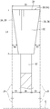
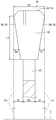
 図1~11を参照して本発明の実施形態を説明する。図1、2に示すようにチップソー10は、丸鋸あるいは側フライス等と同様に円板状である。チップソー10は、台金(ソー本体)12と台金12の外周に設けられる複数のチップ14を有する。台金12は、円板状である。台金12の中心に軸方向に貫通する円形の嵌合孔16が形成される。図3、4に示すように台金12の台金厚U1は、撓み剛性を鑑みて決定される。台金12の外径D1が400mmの場合、台金厚U1は、2.5~8mm、例えば3.2mmである。 Embodiments of the present invention will be described with reference to FIGS. As shown in FIGS. 1 and 2, the tip saw 10 has a disk shape like a circular saw or a side milling cutter. The chip saw 10 includes a base metal (saw body) 12 and a plurality of chips 14 provided on the outer periphery of the base metal 12. The base metal 12 has a disk shape. A circular fitting hole 16 penetrating in the axial direction is formed in the center of the base metal 12. As shown in FIGS. 3 and 4, the base metal thickness U1 of the base metal 12 is determined in view of the bending rigidity. When the outer diameter D1 of the base metal 12 is 400 mm, the base metal thickness U1 is 2.5 to 8 mm, for example, 3.2 mm.
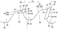
 チップソー10は、図2に示すように台金12の外周に複数の刃取付部20を有する。複数の刃取付部20は、例えば等中心角間隔で配される。刃取付部20は、台金12から径方向に突出し、略山形状である。刃取付部20は、最も径方向外方に頂点部22を有する。頂点部22は、刃取付部20の外周縁の回転方向Fnの先端に位置する。 The tip saw 10 has a plurality of blade mounting portions 20 on the outer periphery of the base metal 12 as shown in FIG. The plurality of blade mounting portions 20 are arranged, for example, at equal central angle intervals. The blade mounting portion 20 protrudes from the base metal 12 in the radial direction and has a substantially mountain shape. The blade mounting portion 20 has a vertex portion 22 at the outermost radial direction. The apex portion 22 is located at the tip of the outer peripheral edge of the blade mounting portion 20 in the rotational direction Fn.
 刃取付部20は、図2に示すように刃取付面24と外周傾斜面26を有する。刃取付面24は、頂点部22から径方向内方へ延出し、外周傾斜面26よりも回転方向Fn側に位置する。外周傾斜面26は、頂点部22から回転方向Fnと反対方向へ延出し、刃取付部20の外周縁を形成する。外周傾斜面26は、第一外周傾斜面26aと第二外周傾斜面26bを有する。第一外周傾斜面26aは、頂点部22から回転方向Fnと反対方向にかつ径方向内方に向けて延出する。第二外周傾斜面26bは、第一外周傾斜面26aから第一外周傾斜面26aよりも大きな傾斜角で径方向内方に向けて延出する。 The blade mounting portion 20 has a blade mounting surface 24 and an outer peripheral inclined surface 26 as shown in FIG. The blade mounting surface 24 extends radially inward from the apex portion 22 and is positioned on the rotational direction Fn side with respect to the outer peripheral inclined surface 26. The outer peripheral inclined surface 26 extends from the apex portion 22 in the direction opposite to the rotation direction Fn, and forms the outer peripheral edge of the blade mounting portion 20. The outer peripheral inclined surface 26 has a first outer peripheral inclined surface 26a and a second outer peripheral inclined surface 26b. The first outer peripheral inclined surface 26a extends from the apex portion 22 in a direction opposite to the rotational direction Fn and radially inward. The second outer peripheral inclined surface 26b extends radially inward from the first outer peripheral inclined surface 26a at a larger inclination angle than the first outer peripheral inclined surface 26a.
 図2に示すように第二外周傾斜面26bと刃取付面24の間に円弧面28が形成される。円弧面28は、各刃取付部20の間にて径方向内方に凹み、ガレット29を形成する。円弧面28と刃取付面24の間には、チップ14が着座可能な段差状の棚が形成される。台金12には、厚み方向に貫通する図示省略のスリットが形成されても良い。台金12には、ガレット29から径方向内方に向かって延出する図示省略のスリット、あるいは他のスリットが形成されても良い。台金12は、先ず鋼板から例えばレーザーにて切り抜かれる。次に刃取付面24等がフライス等で切削される。 As shown in FIG. 2, an arcuate surface 28 is formed between the second outer peripheral inclined surface 26 b and the blade mounting surface 24. The circular arc surface 28 is recessed inward in the radial direction between the blade attachment portions 20 to form a galette 29. A stepped shelf on which the tip 14 can be seated is formed between the arc surface 28 and the blade mounting surface 24. The base metal 12 may be formed with a slit (not shown) penetrating in the thickness direction. The base metal 12 may be formed with a slit (not shown) that extends radially inward from the galette 29 or another slit. The base metal 12 is first cut out from the steel plate with, for example, a laser. Next, the blade mounting surface 24 and the like are cut with a milling cutter or the like.
 刃取付面24には、図2に示すようにチップ14がろう材等で固着される。チップ14は、矩形状であって、超硬合金あるいはサーメット等の硬質材料よりなる硬質チップである。あるいはチップ14は、多結晶ダイヤモンド等の高硬度焼結体よりなる高硬度チップである。チップ14は、アサリ線の長さが相対的に長い長チップ30と、アサリ線の長さが相対的に短い短チップ40を含む。 As shown in FIG. 2, the tip 14 is fixed to the blade mounting surface 24 with a brazing material or the like. The chip 14 has a rectangular shape and is a hard chip made of a hard material such as cemented carbide or cermet. Alternatively, the tip 14 is a high hardness tip made of a high hardness sintered body such as polycrystalline diamond. The chip 14 includes a long chip 30 having a relatively long clam line and a short chip 40 having a relatively short clam line.
 長チップ30は、図2,4に示すようにすくい面32と側面34と外周逃げ面38を有する。すくい面32は、回転方向Fnに向き、外周傾斜面26と対向する。側面34は、すくい面32に対して略直交し、台金12の表面と略平行である。すくい面32と側面34が交差する部位に側面切刃36が形成される。外周逃げ面38は、すくい面32に対して鋭角に延出し、径方向外方に向く。すくい面32と外周逃げ面38が交差する部位に外周切刃39が形成される。 The long chip 30 has a rake face 32, a side face 34, and an outer peripheral flank face 38 as shown in FIGS. The rake face 32 faces the rotation direction Fn and faces the outer peripheral inclined face 26. The side surface 34 is substantially orthogonal to the rake surface 32 and is substantially parallel to the surface of the base metal 12. A side cutting edge 36 is formed at a portion where the rake face 32 and the side face 34 intersect. The outer peripheral flank 38 extends at an acute angle with respect to the rake face 32 and faces radially outward. An outer peripheral cutting edge 39 is formed at a portion where the rake face 32 and the outer peripheral flank 38 intersect.
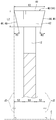
 長チップ30の先端は、図2~4に示すように台金12から径方向外方に突出する。長チップ30は、台金12の厚み方向(軸方向)に僅かに突出する。長チップ30の刃厚T1は、2.6~10mmである。例えば外径D1が400mmの場合、刃厚T1は、4.4mmである。 The tip of the long tip 30 protrudes radially outward from the base metal 12 as shown in FIGS. The long chip 30 slightly protrudes in the thickness direction (axial direction) of the base metal 12. The blade thickness T1 of the long tip 30 is 2.6 to 10 mm. For example, when the outer diameter D1 is 400 mm, the blade thickness T1 is 4.4 mm.
 短チップ40は、基本的に長チップ30と同様に構成される。図2、5、6に示すようにすくい面42、側面44、側面切刃46、外周逃げ面48、外周切刃49を有する。短チップ40の刃厚T2は、2.6~10mmであり、例えば外径D1が400mmの場合に4.4mmである。 The short chip 40 is basically configured similarly to the long chip 30. As shown in FIGS. 2, 5 and 6, it has a rake face 42, a side face 44, a side face cutting edge 46, an outer peripheral flank face 48, and an outer peripheral cutting edge 49. The blade thickness T2 of the short tip 40 is 2.6 to 10 mm, for example, 4.4 mm when the outer diameter D1 is 400 mm.
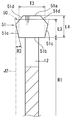
 長チップ30は、図4に示すようにアサリ角R1とアサリ量S1とアサリ線長さL1を有する。側面34は、外周切刃39の軸方向両端から厚み中心方向へ傾斜する。アサリ角R1は、側面34と半径線J1の厚み方向の角度である。換言するとアサリ角R1は、外周切刃39の軸方向両端から側面34が径方向内方に向かう角度である。半径線J1は、外周切刃39あるいはすくい面32の厚み方向外方の端縁から径方向に延出する。半径線J1は、仮想平面H1において外周切刃39の軸方向端縁から延出してチップソー10の中心軸Cに直交する。仮想平面H1は、外周切刃39(長チップ30の径方向外方の先端)とチップソー10の中心軸Cを含む面である。 As shown in FIG. 4, the long chip 30 has a set angle R1, a set amount S1, and a set line length L1. The side surfaces 34 are inclined from both axial ends of the outer peripheral cutting edge 39 toward the thickness center. The set angle R1 is an angle of the side surface 34 and the radial line J1 in the thickness direction. In other words, the set angle R1 is an angle at which the side surface 34 is directed radially inward from both axial ends of the outer peripheral cutting edge 39. The radial line J1 extends in the radial direction from the outer edge of the outer peripheral cutting edge 39 or the rake face 32 in the thickness direction. The radius line J1 extends from the axial end edge of the outer peripheral cutting edge 39 in the virtual plane H1 and is orthogonal to the center axis C of the tip saw 10. The virtual plane H <b> 1 is a surface including the outer peripheral cutting edge 39 (the distal end of the long tip 30 in the radial direction) and the center axis C of the tip saw 10.
 アサリ量S1は、外周切刃39あるいはすくい面32の厚み方向外方の端縁と台金12の表面の厚み方向距離である。アサリ線長さL1は、例えばすくい面32の厚み方向外方の端縁と内方の端縁の径方向長さである。アサリ線長さL1は、半径線J1を基準とする側面34の径方向長さである。 The set amount S1 is the distance in the thickness direction between the outer edge of the outer peripheral cutting edge 39 or the rake face 32 in the thickness direction and the surface of the base metal 12. The clam line length L1 is, for example, the radial length of the outer edge and the inner edge of the rake face 32 in the thickness direction. The clam line length L1 is the radial length of the side surface 34 with respect to the radial line J1.
 長チップ30のアサリ線長さL1は、4mm以上であり、好ましくは4~12mmである。長チップ30のアサリ線長さL1が4mm未満の場合は、加工時における被加工材Wの切断面のうねり量を小さくすることが困難になる。アサリ線長さL1が12mm以上の場合は、チップソー10を安価にすることが困難になる。これらを鑑みてアサリ線長さL1は、より好ましくは4~8mmである。 The clam wire length L1 of the long tip 30 is 4 mm or more, preferably 4 to 12 mm. When the set wire length L1 of the long tip 30 is less than 4 mm, it is difficult to reduce the amount of undulation of the cut surface of the workpiece W during processing. When the set wire length L1 is 12 mm or more, it is difficult to make the tip saw 10 inexpensive. In view of these, the set wire length L1 is more preferably 4 to 8 mm.
 長チップ30のアサリ角R1は、図4を参照するように0°~1.0°である。図7に示す回転軸100とフランジ接触面105が振れると、図8に示す加工断面のうねりXが生じる。長チップ30のアサリ角R1が0°未満(すなわち負のアサリ角)の場合、うねりXによって切削抵抗が大きくなる、あるいはチップ14が焼けるという懸念が生じる。長チップ30のアサリ角R1が1.0°より大きい場合は、うねりXと側面34が接する領域が小さくなる。これにより被加工材Wの切断面のうねり量を小さくすることができないという懸念が生じる。以上を鑑みて長チップ30のアサリ角R1は、0.2°~0.8°であることが好ましく、より好ましくは、0.3°~0.7°である。長チップ30のアサリ角R1は、製作のし易さの点から短チップ40のアサリ角R2と同じであることが好ましい。 The set angle R1 of the long chip 30 is 0 ° to 1.0 ° as shown in FIG. When the rotating shaft 100 and the flange contact surface 105 shown in FIG. 7 are swung, the undulation X of the processed cross section shown in FIG. 8 occurs. When the set angle R1 of the long tip 30 is less than 0 ° (that is, a negative set angle), there is a concern that the cutting resistance is increased by the undulation X or the tip 14 is burnt. When the set angle R1 of the long tip 30 is larger than 1.0 °, a region where the undulation X and the side surface 34 are in contact with each other is small. This raises a concern that the amount of waviness of the cut surface of the workpiece W cannot be reduced. In view of the above, the set angle R1 of the long tip 30 is preferably 0.2 ° to 0.8 °, and more preferably 0.3 ° to 0.7 °. The set angle R1 of the long chip 30 is preferably the same as the set angle R2 of the short chip 40 from the viewpoint of ease of manufacture.
 短チップ40は、図6に示すようにアサリ角R2とアサリ量S2とアサリ線長さL2を有する。アサリ角R2は、側面44と半径線J2の間の角度である。半径線J2、アサリ角R2及びアサリ線長さL2は、長チップ30の半径線J1、アサリ角R1及びアサリ線長さL1と同様に定義される。 The short chip 40 has a set angle R2, a set amount S2, and a set line length L2, as shown in FIG. The set angle R2 is an angle between the side surface 44 and the radial line J2. The radius line J2, the set angle R2, and the set line length L2 are defined in the same manner as the radius line J1, the set angle R1, and the set line length L1 of the long tip 30.
 すなわち半径線J2は、仮想平面H2において外周切刃49の軸方向端縁から延出し、チップソー10の中心軸Cに直交する。仮想平面H2は、外周切刃49(短チップ40の先端)とチップソー10の中心軸Cを含む平面である。アサリ角R2は、側面44と半径線J2の厚み方向の角度である。換言するとアサリ角R2は、外周切刃49の軸方向両端から側面44が径方向内方に向かう角度である。アサリ線長さL2は、半径線J2を基準とする側面44の径方向長さである。アサリ量S2は、台金12の表面と半径線J2の距離である。 That is, the radial line J2 extends from the axial end edge of the outer peripheral cutting edge 49 in the virtual plane H2, and is orthogonal to the central axis C of the tip saw 10. The virtual plane H <b> 2 is a plane including the outer peripheral cutting edge 49 (the tip of the short chip 40) and the center axis C of the chip saw 10. The set angle R2 is an angle of the side surface 44 and the radial line J2 in the thickness direction. In other words, the set angle R2 is an angle at which the side surface 44 is directed radially inward from both axial ends of the outer peripheral cutting edge 49. The clam line length L2 is the radial length of the side surface 44 with respect to the radial line J2. The set amount S2 is a distance between the surface of the base metal 12 and the radius line J2.
 短チップ40のアサリ線の長さL2は、4mm未満である。より好ましくは、短チップ40の全てが1~2mmのアサリ線の長さL2を有する。短チップ40のアサリ線の長さL2が1mm未満である場合、加工時の摩耗による寿命が著しく短くなる。アサリ線長さL2が2mm以上の場合、チップソー10を安価にすることが困難になる。 The length L2 of the set wire of the short chip 40 is less than 4 mm. More preferably, all of the short tips 40 have a set line length L2 of 1 to 2 mm. When the length L2 of the set wire of the short tip 40 is less than 1 mm, the life due to wear during processing is remarkably shortened. When the set wire length L2 is 2 mm or more, it is difficult to make the tip saw 10 inexpensive.
 短チップ40のアサリ角R2は、0°~1.0°である。短チップ40のアサリ角R2が0°未満(すなわち負のアサリ角)の場合、図8に示す加工断面のうねりXによって切削抵抗が大きくなるという懸念が生じる。 The set angle R2 of the short chip 40 is 0 ° to 1.0 °. When the set angle R2 of the short tip 40 is less than 0 ° (that is, a negative set angle), there is a concern that the cutting resistance increases due to the undulation X of the processed cross section shown in FIG.
 長チップ30の数は、図1に示すようにチップ14(長チップ30と短チップ40)の総数の2~15%でかつ2つ以上である。長チップ30の数がチップの総数の2%未満である場合、長チップ30の加工によって被加工材Wの切断面のうねり量を小さくすることが困難になる。長チップ30の数がチップの総数の15%より多い場合、チップソー10を安価にすることが困難になる。チップソー10は、例えば全72個のチップ14を有し、その内長チップ30が6個、短チップ40が66個である。 As shown in FIG. 1, the number of long chips 30 is 2 to 15% of the total number of chips 14 (long chip 30 and short chip 40) and two or more. When the number of long chips 30 is less than 2% of the total number of chips, it becomes difficult to reduce the amount of waviness of the cut surface of the workpiece W by processing the long chips 30. When the number of long chips 30 is more than 15% of the total number of chips, it is difficult to make the chip saw 10 inexpensive. The chip saw 10 has, for example, a total of 72 chips 14, of which 6 are the inner long chips 30 and 66 are the short chips 40.
 長チップ30は、不等中心角間隔に配設しても良い。長チップ30は、好ましくは等中心角間隔に配設される。これにより図7に示す回転軸100とフランジ接触面105の振れにて生じる図8に示す加工断面のうねりXが等間隔で生じる。そのため被加工材Wの切断面を均等に切断でき、被加工材Wの切断面のうねり量を均等に小さくでき得る。 The long chips 30 may be arranged at unequal center angle intervals. The long tips 30 are preferably arranged at equal central angular intervals. As a result, the undulations X of the processed cross section shown in FIG. 8 caused by the swing of the rotating shaft 100 and the flange contact surface 105 shown in FIG. Therefore, the cut surface of the workpiece W can be cut evenly, and the amount of waviness of the cut surface of the workpiece W can be evenly reduced.
 加工装置は、図7に示すように電動モーター(不図示)から水平に突き出した回転軸100を有する。回転軸100には、チップソー10を挟むフランジ103が設けられる。フランジ103は、チップソー10の台金12と接するフランジ接触面105を有する。図1、7に示すように台金12の嵌合孔16に回転軸100が挿入され、締め付けナット107によってチップソー10が回転軸100に装着される。電動モーターが稼働して回転軸100を回転させ、チップソー10が回転方向Fnに所定の回転数Nで回転する。被加工材Wは、所定の送り速度Fでチップソー10に向かって送られ、チップソー10と接触した部分が切断される。 The machining apparatus has a rotating shaft 100 protruding horizontally from an electric motor (not shown) as shown in FIG. The rotary shaft 100 is provided with a flange 103 that sandwiches the tip saw 10. The flange 103 has a flange contact surface 105 that contacts the base 12 of the tip saw 10. As shown in FIGS. 1 and 7, the rotary shaft 100 is inserted into the fitting hole 16 of the base metal 12, and the tip saw 10 is attached to the rotary shaft 100 by the tightening nut 107. The electric motor operates to rotate the rotary shaft 100, and the tip saw 10 rotates at a predetermined rotation speed N in the rotation direction Fn. The workpiece W is fed toward the tip saw 10 at a predetermined feed speed F, and the portion that contacts the tip saw 10 is cut.
 チップソー10を用いて被加工材Wを切削するときの長チップ30の作用を以下に説明する。図8に刃先側面振れ幅AとうねりXが模式的に示される。刃先側面振れ幅Aは、チップソー10が回転軸100とフランジ接触面105が振れることで生じる。うねりXは、刃先側面振れ幅Aを有する状態で被加工材Wを切削した際に生じる。 The operation of the long tip 30 when the workpiece W is cut using the tip saw 10 will be described below. FIG. 8 schematically shows the blade edge side deflection width A and the undulation X. The blade edge side deflection width A is generated when the tip saw 10 swings between the rotary shaft 100 and the flange contact surface 105. The undulation X is generated when the workpiece W is cut in a state having the blade edge side deflection width A.
 チップソー10が全て短チップ40で構成されたと仮定する。短チップ40の外周切刃49は、チップソー10が一回転する際に被加工材Wに波形状のうねりXの軌跡を形成する。短チップ40は、うねりXの経路に沿って被加工材Wを切削する。うねりXは、刃先側面振れ幅Aと同程度の高さを有する。うねりXが被加工材Wの切断面のうねり量になる。チップソー10は、短チップ40に加えて長チップ30を有する。長チップ30は、短チップ40よりも長いアサリ線長さL1を有する。したがってチップソー10が一回転する間に長チップ30がうねりXを平坦に切削する。これにより被加工材Wの切断面のうねり量が小さくなる。 Suppose that the chip saw 10 is composed of all short chips 40. The outer peripheral cutting edge 49 of the short tip 40 forms a wave-shaped waviness X trajectory on the workpiece W when the tip saw 10 rotates once. The short chip 40 cuts the workpiece W along the path of the undulation X. The undulation X has a height comparable to the blade edge side deflection width A. The undulation X becomes the undulation amount of the cut surface of the workpiece W. The tip saw 10 has a long tip 30 in addition to the short tip 40. The long chip 30 has a set line length L1 longer than that of the short chip 40. Accordingly, the long tip 30 cuts the undulation X flatly while the tip saw 10 rotates once. Thereby, the amount of waviness of the cut surface of the workpiece W is reduced.
 うねりXの形は、図7、8に示すようにチップソー10の回転数Nと、被加工材Wの送り速度Fと、刃先側面振れ幅Aの3つの要素が影響する。うねりXは、短チップ40の外周切刃49がチップソー10の一回転当たりに被加工材Wに対して波打って切削する軌跡と近似する。 As shown in FIGS. 7 and 8, the shape of the undulation X is affected by three factors, that is, the rotational speed N of the tip saw 10, the feed speed F of the workpiece W, and the blade edge side deflection A. The undulation X approximates a trajectory that the outer peripheral cutting edge 49 of the short tip 40 undulates and cuts the workpiece W per one rotation of the tip saw 10.
 距離Ymmは、チップソー10の一回転当たりのうねりXの長さである。距離Ymmは、送り速度Fm/minと回転数Nrpmと関係する。距離Ymmは、Y=(F×1000)/Nで近似される。うねりXの最大高さは、刃先側面振れ幅Aと同程度の高さを有する。うねりXは、図8の仮想線で示す三角形に近似され、三角形は、底辺が距離Y、高さが刃先側面振れ幅Aである。三角形の角度γは、“γ=2A/Y”で近似される。長チップ30のアサリ角R1は、うねりXにおける角度γに対して、より小さくすることで被加工材Wの切断面のうねり量を小さくし得る。 The distance Ymm is the length of the undulation X per rotation of the tip saw 10. The distance Ymm is related to the feed speed Fm / min and the rotation speed Nrpm. The distance Ymm is approximated by Y = (F × 1000) / N. The maximum height of the undulation X has the same height as the blade edge side deflection width A. The undulation X is approximated by a triangle indicated by a virtual line in FIG. 8, and the triangle has a distance Y at the bottom and a side deflection width A at the blade edge. The angle γ of the triangle is approximated by “γ = 2A / Y”. The amount of waviness of the cut surface of the workpiece W can be reduced by making the set angle R1 of the long tip 30 smaller than the angle γ of the waviness X.
 うねりXの角度γと長チップ30のアサリ角R1の関係に鑑み、チップソー10は、回転数Nが1000~5000rpmの範囲で使用されることが好ましい。 In view of the relationship between the angle γ of the undulation X and the set angle R1 of the long tip 30, the tip saw 10 is preferably used in the range of the rotation speed N of 1000 to 5000 rpm.
 うねりXの角度γと長チップ30のアサリ角R1の関係に鑑み、被加工材Wの送り速度Fは、5~120m/minの範囲である。送り速度Fが5m/min未満の場合は、被加工材Wの切断面のうねり量が小さくなるが加工速度が遅くなる。送り速度Fが120m/minより大きい場合は、被加工材Wの切断面のうねり量が大きくなる。加工速度と被加工材Wの切断面のうねり量を鑑みると、被加工材Wの送り速度Fは、20~80m/minの範囲であることが好ましい。 In view of the relationship between the angle γ of the undulation X and the set angle R1 of the long tip 30, the feed speed F of the workpiece W is in the range of 5 to 120 m / min. When the feed speed F is less than 5 m / min, the amount of waviness of the cut surface of the workpiece W is reduced, but the processing speed is slowed down. When the feed speed F is greater than 120 m / min, the amount of waviness on the cut surface of the workpiece W increases. In view of the processing speed and the amount of waviness of the cut surface of the workpiece W, the feed speed F of the workpiece W is preferably in the range of 20 to 80 m / min.
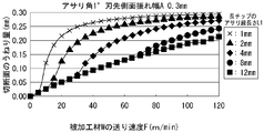
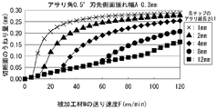
 長チップ30のアサリ線長さL1と被加工材Wの切断面のうねり量の関係について以下に説明する。例として刃先側面振れ幅Aが0.3mmである場合における関係について説明する。短チップ40としてアサリ角R2が1°、アサリ線長さL2が1mmのチップを取付けた。長チップ30が取り付く位置にも短チップ40と同じチップ、すなわちアサリ角R1が1°、アサリ線長さL1が1mmのチップを取付けた。そして各送り速度Fにおける被加工材Wの切断面のうねり量を測定した。次に長チップ30が取り付く位置にアサリ角R1が1°、アサリ線長さL1が2mm、4mm、8mm、12mmの各チップを取付けた。各送り速度Fにおける被加工材Wの切断面のうねり量を測定し、その結果を図9に示した。 The relationship between the set wire length L1 of the long tip 30 and the amount of waviness of the cut surface of the workpiece W will be described below. As an example, the relationship when the blade edge side deflection A is 0.3 mm will be described. A chip having a set angle R2 of 1 ° and a set line length L2 of 1 mm was attached as the short chip 40. The same tip as the short tip 40, that is, a tip having a set angle R1 of 1 ° and a set length L1 of 1 mm was attached to the position where the long tip 30 is attached. And the amount of waviness of the cut surface of the workpiece W at each feed rate F was measured. Next, chips having a set angle R1 of 1 ° and a set line length L1 of 2 mm, 4 mm, 8 mm, and 12 mm were attached to positions where the long chips 30 were attached. The amount of waviness of the cut surface of the workpiece W at each feed rate F was measured, and the results are shown in FIG.
 次にアサリ角R1が0.5°である場合における上記関係について説明する。チップソー10の刃先側面振れ幅Aが0.3mmにおいて、短チップ40としてアサリ角R2が0.5°、アサリ線長さL2が1mmのチップを取付けた。長チップ30が取り付く位置にも短チップ40と同じチップ、すなわちアサリ角R1が0.5°、アサリ線長さL1が1mmのチップを取付けた。そして各送り速度Fにおける被加工材Wの切断面のうねり量を測定した。次に長チップ30が取り付く位置にアサリ角R1が0.5°、アサリ線長さL1が2mm、4mm、8mm、12mmの各チップを取付けた。各送り速度Fにおける被加工材Wの切断面のうねり量を測定し、その結果を図10に示した。 Next, the above relationship when the set angle R1 is 0.5 ° will be described. When the blade edge side deflection width A of the tip saw 10 was 0.3 mm, a tip having a set angle R2 of 0.5 ° and a set length L2 of 1 mm was attached as the short tip 40. The same tip as the short tip 40, that is, a tip having a set angle R1 of 0.5 ° and a set length L1 of 1 mm was attached to the position where the long tip 30 is attached. And the amount of waviness of the cut surface of the workpiece W at each feed rate F was measured. Next, chips having a set angle R1 of 0.5 ° and a set line length L1 of 2 mm, 4 mm, 8 mm, and 12 mm were attached to the position where the long chip 30 was attached. The amount of waviness of the cut surface of the workpiece W at each feed rate F was measured, and the results are shown in FIG.
 図9、10からアサリ線長さL1が1mm、2mmのチップソーは、被加工材Wの送り速度Fが20m/min未満において被加工材Wの切断面のうねり量が著しく大きくなることがわかった。送り速度Fが20m/min近傍においてもうねり量が大きくなることがわかった。被加工材Wの送り速度Fは、20m/min以上の範囲で用いられる。そのためアサリ線長さL1が1mm、2mmのチップを長チップ30として使用することは好ましくない。 9 and 10, it was found that the tip saw with the clam line length L1 of 1 mm and 2 mm has a remarkably large waviness of the cut surface of the workpiece W when the feed speed F of the workpiece W is less than 20 m / min. . It was found that the amount of swell increases when the feed speed F is around 20 m / min. The feed speed F of the workpiece W is used in a range of 20 m / min or more. For this reason, it is not preferable to use a chip having a clam line length L1 of 1 mm or 2 mm as the long chip 30.
 図9からアサリ線長さL1が4mm、アサリ角R1が1°の場合、被加工材Wの送り速度Fが30m/min付近において被加工材Wの切断面のうねり量が急激に大きくなることがわかった。例えばうねり量が0.08mm以上になることがわかった。図10からアサリ線長さL1が4mm、アサリ角R1が0.5°の場合、被加工材Wの送り速度Fが25m/min付近において被加工材Wの切断面のうねり量が急激に大きくなることがわかった。例えばうねり量が0.04mm以上になることがわかった。 From FIG. 9, when the set wire length L1 is 4 mm and the set angle R1 is 1 °, the amount of waviness of the cut surface of the workpiece W increases rapidly when the feed speed F of the workpiece W is around 30 m / min. I understood. For example, it has been found that the amount of undulation is 0.08 mm or more. From FIG. 10, when the set wire length L1 is 4 mm and the set angle R1 is 0.5 °, the waviness of the cut surface of the workpiece W is rapidly increased when the feed speed F of the workpiece W is around 25 m / min. I found out that For example, it has been found that the amount of undulation is 0.04 mm or more.
 被加工材Wの送り速度Fは、20m/min以上の範囲で用いられる。そのためアサリ線長さL1が4mm以上のチップを長チップ30として使用することは好ましいことがわかった。アサリ角R1が0.5°のチップと、アサリ角R1が1°のチップを比較するとアサリ角R1が0.5°のチップを用いた方が相対的に被加工材Wの切断面のうねり量が小さくなることがわかった。 The feed speed F of the workpiece W is used in a range of 20 m / min or more. Therefore, it has been found that it is preferable to use a chip having a set wire length L1 of 4 mm or more as the long chip 30. Comparing a chip with a set angle R1 of 0.5 ° and a chip with a set angle R1 of 1 °, the undulation of the cut surface of the workpiece W is relatively greater when using a chip with a set angle R1 of 0.5 °. The amount was found to be smaller.
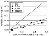
 チップソー10を用いて被加工材Wを加工した際の刃先側面振れ幅Aと被加工材Wの切断面のうねり量の関係を図11に示す。被加工材Wは、図7では詳細な図示を省略しているが、例えばメラミン貼りMDFである。メラミン貼りMDFは、基材であるMDFと、MDFの表面に熱圧されるメラミン含侵シートを一体に有する。MDFは、木質ボードとして木材の小片を接着剤と混合し熱圧成型して形成される。メラミン貼りMDFの厚みは、15mmのものを2枚重ねした30mmである。 FIG. 11 shows the relationship between the cutting edge side deflection width A and the amount of waviness of the cut surface of the workpiece W when the workpiece W is machined using the tip saw 10. Although the detailed illustration is abbreviate | omitted in FIG. 7, the workpiece W is melamine pasting MDF, for example. The melamine-attached MDF integrally has a base material MDF and a melamine-impregnated sheet that is hot-pressed on the surface of the MDF. MDF is formed as a wooden board by mixing a small piece of wood with an adhesive and hot pressing. The thickness of the melamine-attached MDF is 30 mm, which is a stack of two 15 mm ones.
 実施例1のチップソー10の外径D1は400mm、台金12の台金厚U1は3.2mm、穴径D2は75mm、刃取付部20の数は72個である。実施例1のチップソー10は、6個の長チップ30を有する。長チップ30の刃厚T1は4.4mm、アサリ線長さL1は8mm、アサリ角R1は1°である。長チップ30は、中心角が60°毎の等中心角間隔に配設される。実施例1のチップソー10は、66個の短チップ40を有する。短チップ40の刃厚T2は4.4mm、アサリ線長さL2は2mm、アサリ角R2は1°である。 The outer diameter D1 of the tip saw 10 of Example 1 is 400 mm, the base metal thickness U1 of the base metal 12 is 3.2 mm, the hole diameter D2 is 75 mm, and the number of blade mounting portions 20 is 72. The chip saw 10 of the first embodiment has six long chips 30. The long tip 30 has a blade thickness T1 of 4.4 mm, a set wire length L1 of 8 mm, and a set angle R1 of 1 °. The long chips 30 are arranged at equal central angle intervals with a central angle of every 60 °. The chip saw 10 of the first embodiment has 66 short chips 40. The short tip 40 has a blade thickness T2 of 4.4 mm, a set wire length L2 of 2 mm, and a set angle R2 of 1 °.
 加工装置のフランジ103の直径は120mm、チップソー10の回転数Nは3600rpm、被加工材Wの送り速度Fは39m/minである。チップソー10の刃先側面振れ幅Aを0.22mmと0.35mmに設定して測定した。測定した値を図11に黒丸で示した。図11に示すように刃先側面振れ幅Aが0.22mmの場合、被加工材Wの切断面のうねり量はおよそ0.03mmであった。刃先側面振れ幅Aが0.35mmの場合、被加工材Wの切断面のうねり量はおよそ0.08mmであった。 The diameter of the flange 103 of the machining apparatus is 120 mm, the rotation speed N of the tip saw 10 is 3600 rpm, and the feed speed F of the workpiece W is 39 m / min. Measurement was performed by setting the side edge runout width A of the tip saw 10 to 0.22 mm and 0.35 mm. The measured values are indicated by black circles in FIG. As shown in FIG. 11, when the blade edge side deflection A was 0.22 mm, the amount of undulation of the cut surface of the workpiece W was approximately 0.03 mm. When the blade edge side deflection A was 0.35 mm, the amount of waviness on the cut surface of the workpiece W was approximately 0.08 mm.
 比較例1~7についても測定した。比較例1~4は、72個の同じチップを有する。チップのアサリ線長さは2mm、アサリ角は1°である。チップソーの刃先側面振れ幅Aを0.10mm、0.15mm、0.45mm、0.52mmに設定した。他の条件は、実施例1と同じである。比較例1~4の測定結果を図11のクロス印で示す。図11に示すように比較例1~4の各うねり量は、およそ0.08mm、およそ0.06mm、およそ0.24mm、およそ0.28mmであった。チップソーの刃先側面振れ幅Aと被加工材Wの切断面のうねり量の関係を近似直線で示した。 Measured for Comparative Examples 1-7. Comparative Examples 1 to 4 have 72 identical chips. The set wire length of the chip is 2 mm, and the set angle is 1 °. The blade edge side runout width A of the tip saw was set to 0.10 mm, 0.15 mm, 0.45 mm, and 0.52 mm. Other conditions are the same as those in the first embodiment. The measurement results of Comparative Examples 1 to 4 are indicated by cross marks in FIG. As shown in FIG. 11, the waviness amounts of Comparative Examples 1 to 4 were approximately 0.08 mm, approximately 0.06 mm, approximately 0.24 mm, and approximately 0.28 mm. The relationship between the tip side runout width A of the tip saw and the amount of waviness of the cut surface of the workpiece W is shown by an approximate straight line.
 比較例5は、72個の同じチップを有する。チップのアサリ線長さは6.5mm、アサリ角は1°である。チップソーの刃先側面振れ幅Aを0.50mmに設定し、他の条件を実施例1と同じにした。比較例5の測定結果を図11に黒三角印で示し、比較例5のうねり量は、およそ0.10mmであった。刃先側面振れ幅Aとうねり量の関係を近似直線で示した。 Comparative Example 5 has 72 identical chips. The chip has a set line length of 6.5 mm and a set angle of 1 °. The blade edge side deflection A of the tip saw was set to 0.50 mm, and other conditions were the same as those in Example 1. The measurement results of Comparative Example 5 are shown by black triangles in FIG. 11, and the amount of undulation of Comparative Example 5 was about 0.10 mm. The relationship between the blade edge side deflection A and the amount of waviness is shown by an approximate straight line.
 比較例6と7は、72個の同じチップを有する。チップのアサリ線長さは6.5mm、アサリ角は40′である。チップソーの刃先側面振れ幅Aを0.04と0.52mmに設定し、他の条件を実施例1と同じにした。比較例6と7の測定結果を図11に黒四角印で示し、比較例6、7のうねり量はそれぞれおよそ0.01mm、およそ0.08mmであった。刃先側面振れ幅Aとうねり量の関係を近似直線で示した。 Comparative examples 6 and 7 have 72 identical chips. The chip has a set line length of 6.5 mm and a set angle of 40 '. The blade edge side deflection width A of the tip saw was set to 0.04 and 0.52 mm, and other conditions were the same as those in Example 1. The measurement results of Comparative Examples 6 and 7 are shown by black square marks in FIG. 11, and the swell amounts of Comparative Examples 6 and 7 were approximately 0.01 mm and approximately 0.08 mm, respectively. The relationship between the blade edge side deflection A and the amount of waviness is shown by an approximate straight line.
 図11のクロス印で示す比較例1~4は、全チップがアサリ線長さを2mmとする短チップ40である。この場合、回転軸100とフランジ接触面105の振れによって刃先側面振れ幅Aが大きくなるにつれて被加工材Wの切断面のうねり量が大きくなることがわかった。 In Comparative Examples 1 to 4 indicated by cross marks in FIG. 11, all chips are short chips 40 having a clam line length of 2 mm. In this case, it has been found that the amount of waviness of the cut surface of the workpiece W increases as the blade edge side deflection width A increases due to the swing of the rotary shaft 100 and the flange contact surface 105.
 図11の黒三角印と黒四角印で示す比較例5~7は、全チップのアサリ線長さが6.5mmであり4mm以上である。この場合、回転軸100とフランジ接触面105の振れによって刃先側面振れ幅Aが大きくなっても、クロス印で示す比較例1~4に比べて被加工材Wの切断面のうねり量が小さくなることがわかった。しかし比較例5~7は、安価にすることが容易でない。 In Comparative Examples 5 to 7 indicated by the black triangle mark and the black square mark in FIG. 11, the clam line length of all the chips is 6.5 mm, which is 4 mm or more. In this case, even if the blade edge side deflection A is increased due to the deflection of the rotary shaft 100 and the flange contact surface 105, the amount of waviness of the cut surface of the workpiece W is smaller than in Comparative Examples 1 to 4 indicated by cross marks. I understood it. However, it is not easy to make Comparative Examples 5 to 7 inexpensive.
 図11の黒丸印で示す実施例1は、6個の長チップ30を有する。長チップ30の数は、全チップ72個の2~15%の範囲内である。この場合でも、被加工材Wの切断面のうねり量は、黒三角印と黒四角印で示す比較例5~7とほぼ同じであることがわかった。したがって長チップ30の数をたった全チップの2~15%にしても、当業者が予想できないほどの大きな効果、すなわち全チップを長チップ30にした場合と同じ効果を得ることがわかった。かくしてチップソー10は、被加工材Wの切断面のうねり量を十分に小さくできかつ安価に構成され得る。 Example 1 indicated by black circles in FIG. 11 has six long chips 30. The number of long chips 30 is in the range of 2 to 15% of the total 72 chips. Even in this case, it was found that the waviness of the cut surface of the workpiece W was almost the same as that of Comparative Examples 5 to 7 indicated by black triangle marks and black square marks. Therefore, it has been found that even if the number of long chips 30 is 2 to 15% of all the chips, a great effect that cannot be predicted by those skilled in the art, that is, the same effect as when all the long chips 30 are long chips 30 is obtained. Thus, the tip saw 10 can sufficiently reduce the amount of waviness of the cut surface of the workpiece W and can be configured at low cost.
 以上のようにチップソー10は、回転軸100とフランジ接触面105の振れが生じる場合においても被加工材Wの切断面のうねり量を十分に小さくできる。さらにチップソー10は、安価に構成され得る。長チップ30と短チップ40は、多結晶ダイヤモンド等の高価な材料で形成される。そのため長チップ30は、短チップ40に比べて非常に高い。しかし長チップ30の数がチップの総数の2~15%でとても少ない。そのためチップソー10は、安価に構成され得る。また短チップ40が多いため、総チップの側面面積が小さくなる。これによりチップを研磨する際の研磨時間が短くなる。 As described above, the tip saw 10 can sufficiently reduce the waviness of the cut surface of the workpiece W even when the rotating shaft 100 and the flange contact surface 105 are shaken. Further, the tip saw 10 can be configured at low cost. The long chip 30 and the short chip 40 are formed of an expensive material such as polycrystalline diamond. Therefore, the long chip 30 is much higher than the short chip 40. However, the number of long chips 30 is very small, 2 to 15% of the total number of chips. Therefore, the tip saw 10 can be configured at low cost. Further, since there are many short chips 40, the side surface area of the total chip is reduced. This shortens the polishing time for polishing the chip.
 本発明の形態を上記構造を参照して説明したが、本発明の目的を逸脱せずに多くの交代、改良、変更が可能であることは当業者であれば明らかである。したがって本発明の形態は、添付された請求項の目的を逸脱しない全ての交代、改良、変更を含み得る。例えば本発明の形態は、前記特別な構造に限定されず、下記のように変更が可能である。 Although the embodiments of the present invention have been described with reference to the above structure, it will be apparent to those skilled in the art that many substitutions, improvements, and changes can be made without departing from the object of the present invention. Accordingly, the embodiments of the invention may include all alterations, modifications, and changes that do not depart from the scope of the appended claims. For example, the form of the present invention is not limited to the special structure, and can be modified as follows.
 長チップ30の外周切刃39および/または短チップ40の外周切刃49にリード角を設けても良い。リード角を設けることで、切断面をきれいに仕上げ得る。特に、回転軸100とフランジ接触面105の振れに伴う刃先側面振れ幅Aが大きいときに好適である。 A lead angle may be provided on the outer peripheral cutting edge 39 of the long tip 30 and / or the outer peripheral cutting edge 49 of the short tip 40. By providing a lead angle, the cut surface can be finished cleanly. It is particularly suitable when the blade edge side deflection width A accompanying the deflection of the rotary shaft 100 and the flange contact surface 105 is large.
 長チップ30の外周切刃39および/または短チップ40の外周切刃49に研ぎ角を設けても良い。研ぎ角を設けることで、切断面をきれいに仕上げ得る。 A sharpening angle may be provided on the outer peripheral cutting edge 39 of the long tip 30 and / or the outer peripheral cutting edge 49 of the short tip 40. By providing a sharpening angle, the cut surface can be finished cleanly.
 図12に示すように長チップ30の外周切刃39の両端に面取りを設けても良い。図13に示すように短チップ40の外周切刃49の両端に面取りを設けても良い。 As shown in FIG. 12, chamfering may be provided at both ends of the outer peripheral cutting edge 39 of the long tip 30. As shown in FIG. 13, chamfering may be provided at both ends of the outer peripheral cutting edge 49 of the short chip 40.
 チップソー10は、図14,15に示す第1と第2の短チップ50,51と図16に示す長チップ52を有していても良い。第1の短チップ50は、図6に示す短チップ40と同様に形成される。短チップ50のすくい面は、長さT3の下辺50bと、長さT4の上辺50aと、アサリ線長さL3を有する。下辺50bは、台金12の中心から距離R1にて設置される。短チップ50,51と長チップ52は、同じアサリ角R3を有する。 The chip saw 10 may have first and second short chips 50 and 51 shown in FIGS. 14 and 15 and a long chip 52 shown in FIG. The first short chip 50 is formed in the same manner as the short chip 40 shown in FIG. The rake face of the short chip 50 has a lower side 50b of a length T3, an upper side 50a of a length T4, and a clam line length L3. The lower side 50b is installed at a distance R1 from the center of the base metal 12. The short chips 50 and 51 and the long chip 52 have the same set angle R3.
 図15に示す第2の短チップ51は、図13に示す短チップ40と同様に、両端に面取り51dを有する。第2の短チップ51のすくい面は、上辺51aと下辺51bを有する。下辺51bは、図14に示す短チップ50の下辺50bと同じ長さT3を有する。下辺51bは、下辺50bと同様に台金12の中心から距離R1にて設置される。第2の短チップ51のすくい面の上辺51aは、第1の短チップ50の上辺50aよりも径方向外方に位置する(L4>L3)。 The second short chip 51 shown in FIG. 15 has chamfers 51d at both ends, similarly to the short chip 40 shown in FIG. The rake face of the second short chip 51 has an upper side 51a and a lower side 51b. The lower side 51b has the same length T3 as the lower side 50b of the short chip 50 shown in FIG. The lower side 51b is installed at a distance R1 from the center of the base metal 12 similarly to the lower side 50b. The upper side 51a of the rake face of the second short chip 51 is located radially outward from the upper side 50a of the first short chip 50 (L4> L3).
 図16に示す長チップ52は、図4に示す長チップ30と同様に形成される。長チップ52のすくい面は、上辺52aと下辺52bとアサリ線長さL5(L5>L4>L3)を有する。上辺52aは、第1の短チップ50の上辺50aと同じ長さT4を有する。長チップ52の上辺52aは、第1の短チップ50の上辺50aと同様に台金12の中心から距離R1+L3において設置される。 16 is formed in the same manner as the long chip 30 shown in FIG. The rake face of the long chip 52 has an upper side 52a, a lower side 52b, and a clam line length L5 (L5> L4> L3). The upper side 52a has the same length T4 as the upper side 50a of the first short chip 50. The upper side 52a of the long chip 52 is set at a distance R1 + L3 from the center of the base metal 12 in the same manner as the upper side 50a of the first short chip 50.
 第1の短チップ50と第2の短チップ51は、基本的に交互に配設される。いくつかの第2の短チップ51間に第1の短チップ50に代えて図16の長チップ52が配設される。あるいはいくつかの第1の短チップ50間に図15の第2の短チップ51に代えて図16の長チップ52が配設される。あるいは複数の第1の短チップ50と複数の第2の短チップ51が交互に配設され、いくつかの長チップ52が所定場所に設けられても良い。 The first short chips 50 and the second short chips 51 are basically arranged alternately. A long chip 52 shown in FIG. 16 is disposed between several second short chips 51 instead of the first short chips 50. Alternatively, the long chips 52 shown in FIG. 16 are arranged between several first short chips 50 instead of the second short chips 51 shown in FIG. Alternatively, a plurality of first short chips 50 and a plurality of second short chips 51 may be alternately arranged, and several long chips 52 may be provided at predetermined locations.
 図7に示すようにチップソー10によって被加工材Wをいわゆるダウンカットによって加工しても良い。あるいはチップソー10の取付けの向きを回転軸100に対して反対にする。チップソー10の回転方向Fnを反対にする。これによりチップソー10によって被加工材Wをいわゆるアップカットによって加工しても良い。 As shown in FIG. 7, the workpiece W may be processed by a so-called down cut with the tip saw 10. Alternatively, the tip saw 10 is mounted in the opposite direction with respect to the rotating shaft 100. The rotation direction Fn of the tip saw 10 is reversed. Thus, the workpiece W may be processed by the so-called up-cut with the tip saw 10.

Claims (3)

  1.  チップソーであって、
     台金と、前記台金の外周に設けられる複数のチップを有し、
     前記複数のチップは、4mm以上の半径方向のアサリ線長さを有する長チップと、4mm未満の半径方向のアサリ線長さを有する短チップを含み、
     前記長チップの数が、前記長チップと前記短チップの総数の2~15%でかつ2つ以上であるチップソー。
    A chipsaw,
    A base metal and a plurality of chips provided on an outer periphery of the base metal;
    The plurality of tips includes a long tip having a radial set length of 4 mm or more and a short tip having a radial set length of less than 4 mm,
    A chip saw in which the number of the long chips is 2 to 15% of the total number of the long chips and the short chips and two or more.
  2.  請求項1に記載のチップソーであって、
     前記長チップは、半径線から厚み方向に0°~1.0°のアサリ角を有するチップソー。
    The tip saw according to claim 1,
    The long tip is a tip saw having a set angle of 0 ° to 1.0 ° in the thickness direction from the radial line.
  3.  請求項1または2に記載のチップソーであって、
     前記短チップの全てが、1~2mmのアサリ線の長さを有するチップソー。
    The tip saw according to claim 1 or 2,
    A tip saw in which all of the short tips have a length of clam wire of 1 to 2 mm.
PCT/JP2013/075878 2012-10-22 2013-09-25 Saw blade WO2014065069A1 (en)

Priority Applications (3)

Application Number Priority Date Filing Date Title
US14/437,657 US20150251259A1 (en) 2012-10-22 2013-09-25 Rotary saw blade with tips of varying length
EP13849853.0A EP2910327A4 (en) 2012-10-22 2013-09-25 Saw blade
JP2014543204A JP5951788B2 (en) 2012-10-22 2013-09-25 Tip saw

Applications Claiming Priority (2)

Application Number Priority Date Filing Date Title
JP2012-232828 2012-10-22
JP2012232828 2012-10-22

Publications (1)

Publication Number Publication Date
WO2014065069A1 true WO2014065069A1 (en) 2014-05-01

Family

ID=50544449

Family Applications (1)

Application Number Title Priority Date Filing Date
PCT/JP2013/075878 WO2014065069A1 (en) 2012-10-22 2013-09-25 Saw blade

Country Status (4)

Country Link
US (1) US20150251259A1 (en)
EP (1) EP2910327A4 (en)
JP (1) JP5951788B2 (en)
WO (1) WO2014065069A1 (en)

Cited By (3)

* Cited by examiner, † Cited by third party
Publication number Priority date Publication date Assignee Title
JP2016049762A (en) * 2014-08-29 2016-04-11 小林 修 Rotary cutter for cutting ceramic industry system external facing material
JPWO2016178307A1 (en) * 2015-05-07 2018-02-22 兼房株式会社 Circular saw
WO2022137576A1 (en) * 2020-12-22 2022-06-30 有限会社辰野目立加工所 Tip saw

Families Citing this family (2)

* Cited by examiner, † Cited by third party
Publication number Priority date Publication date Assignee Title
JP6399661B2 (en) * 2013-06-24 2018-10-03 兼房株式会社 Manufacturing method of circular saw with tip
DE102018123117A1 (en) * 2018-09-20 2020-03-26 Leitz Gmbh & Co. Kg Tangentially tipped circular saw blade and process for resharpening it

Citations (5)

* Cited by examiner, † Cited by third party
Publication number Priority date Publication date Assignee Title
JPH0524305U (en) * 1991-04-30 1993-03-30 株式会社松岡カツター製作所 Circular saw
JP2000254822A (en) * 1999-03-09 2000-09-19 Moriyama:Kk Chip saw
JP3170498B2 (en) 1999-01-29 2001-05-28 兼房株式会社 Circular saw
JP2002059403A (en) * 2000-08-14 2002-02-26 Misawa Homes Co Ltd Rotary edge tool
DE10253711A1 (en) * 2002-11-18 2004-06-03 Arntz Gmbh + Co. Kg Saw blade, especially a band saw blade or circular saw blade, for cutting metal comprises a base body with non-set teeth arranged in a two groups of different teeth

Family Cites Families (3)

* Cited by examiner, † Cited by third party
Publication number Priority date Publication date Assignee Title
AU2001283009A1 (en) * 2000-07-31 2002-02-13 Shaw Millwork, Inc. Saw blade for a coping apparatus
US20100011933A1 (en) * 2006-06-01 2010-01-21 Rex Cameron Lucas Saw blade insert and method and means of sharpening same
US9248518B2 (en) * 2010-06-30 2016-02-02 Irwin Industrial Tool Company Saw blade tooth form for abusive cutting applications

Patent Citations (5)

* Cited by examiner, † Cited by third party
Publication number Priority date Publication date Assignee Title
JPH0524305U (en) * 1991-04-30 1993-03-30 株式会社松岡カツター製作所 Circular saw
JP3170498B2 (en) 1999-01-29 2001-05-28 兼房株式会社 Circular saw
JP2000254822A (en) * 1999-03-09 2000-09-19 Moriyama:Kk Chip saw
JP2002059403A (en) * 2000-08-14 2002-02-26 Misawa Homes Co Ltd Rotary edge tool
DE10253711A1 (en) * 2002-11-18 2004-06-03 Arntz Gmbh + Co. Kg Saw blade, especially a band saw blade or circular saw blade, for cutting metal comprises a base body with non-set teeth arranged in a two groups of different teeth

Non-Patent Citations (1)

* Cited by examiner, † Cited by third party
Title
See also references of EP2910327A4 *

Cited By (3)

* Cited by examiner, † Cited by third party
Publication number Priority date Publication date Assignee Title
JP2016049762A (en) * 2014-08-29 2016-04-11 小林 修 Rotary cutter for cutting ceramic industry system external facing material
JPWO2016178307A1 (en) * 2015-05-07 2018-02-22 兼房株式会社 Circular saw
WO2022137576A1 (en) * 2020-12-22 2022-06-30 有限会社辰野目立加工所 Tip saw

Also Published As

Publication number Publication date
JPWO2014065069A1 (en) 2016-09-08
EP2910327A4 (en) 2016-07-06
JP5951788B2 (en) 2016-07-13
EP2910327A1 (en) 2015-08-26
US20150251259A1 (en) 2015-09-10

Similar Documents

Publication Publication Date Title
RU2510819C1 (en) Machining tool
JP5951788B2 (en) Tip saw
JP6347258B2 (en) Radius end mill and cutting method
WO2011046121A1 (en) Cutting insert and rotary tool with a replaceable blade edge
JP2013031911A5 (en) End mill
RU2592649C2 (en) Machining tool
US7117863B1 (en) Saw blade for cutting fiber cement
JP6879668B2 (en) Cutting method
JP5652540B2 (en) Guide pad, cutting tool body and cutting tool
JP2003053620A (en) Cutting bit and milling tool for milling operation
WO2015098360A1 (en) Cutter
JP6544859B2 (en) Cutter blade
JPH07299634A (en) End mill
JP2008213117A (en) Rotating saw
JP2003266231A (en) End mill and machining method and machine tool using end mill
JP2019077080A (en) Chip saw
CN210525162U (en) Cutting saw
WO2015064010A1 (en) Blade for cutting wood and cutting tool using same
JP2008229764A (en) Rotary tool and machining method
JPWO2016039347A1 (en) Replaceable cutting edge rotary cutting tool
JP4652187B2 (en) Rotary cutting tool
JP6132210B2 (en) Rotary cutting tool for work materials containing fiber
WO2021210449A1 (en) Chip saw
CN211804052U (en) Disc knife
JP5929144B2 (en) Hard sintered ball end mill

Legal Events

Date Code Title Description
121 Ep: the epo has been informed by wipo that ep was designated in this application

Ref document number: 13849853

Country of ref document: EP

Kind code of ref document: A1

ENP Entry into the national phase

Ref document number: 2014543204

Country of ref document: JP

Kind code of ref document: A

NENP Non-entry into the national phase

Ref country code: DE

WWE Wipo information: entry into national phase

Ref document number: 14437657

Country of ref document: US

WWE Wipo information: entry into national phase

Ref document number: 2013849853

Country of ref document: EP