WO2014064820A1 - 電子機器 - Google Patents
電子機器 Download PDFInfo
- Publication number
- WO2014064820A1 WO2014064820A1 PCT/JP2012/077658 JP2012077658W WO2014064820A1 WO 2014064820 A1 WO2014064820 A1 WO 2014064820A1 JP 2012077658 W JP2012077658 W JP 2012077658W WO 2014064820 A1 WO2014064820 A1 WO 2014064820A1
- Authority
- WO
- WIPO (PCT)
- Prior art keywords
- light source
- light
- switch
- operation panel
- unit
- Prior art date
- Legal status (The legal status is an assumption and is not a legal conclusion. Google has not performed a legal analysis and makes no representation as to the accuracy of the status listed.)
- Ceased
Links
Images


Classifications
-
- H—ELECTRICITY
- H01—ELECTRIC ELEMENTS
- H01H—ELECTRIC SWITCHES; RELAYS; SELECTORS; EMERGENCY PROTECTIVE DEVICES
- H01H13/00—Switches having rectilinearly-movable operating part or parts adapted for pushing or pulling in one direction only, e.g. push-button switch
- H01H13/70—Switches having rectilinearly-movable operating part or parts adapted for pushing or pulling in one direction only, e.g. push-button switch having a plurality of operating members associated with different sets of contacts, e.g. keyboard
- H01H13/83—Switches having rectilinearly-movable operating part or parts adapted for pushing or pulling in one direction only, e.g. push-button switch having a plurality of operating members associated with different sets of contacts, e.g. keyboard characterised by legends, e.g. Braille, liquid crystal displays, light emitting or optical elements
-
- H—ELECTRICITY
- H01—ELECTRIC ELEMENTS
- H01H—ELECTRIC SWITCHES; RELAYS; SELECTORS; EMERGENCY PROTECTIVE DEVICES
- H01H2219/00—Legends
- H01H2219/054—Optical elements
- H01H2219/06—Reflector
Definitions
- the present invention relates to an electronic device including an operation panel having a switch and the like.
- a user operates a switch on an operation panel of an electronic device and uses the electronic device.
- electronic devices for example, a projection display device that projects an image is known.
- the projection display device includes an operation panel, and the user can switch the operation state of the projection display device by operating a switch on the operation panel.
- the projection display device may be used in a dark place.
- the user cannot grasp the position of the switch on the operation panel because the operation panel is not exposed to light. Therefore, there is a problem that it is difficult for the user to operate the operation panel.
- Patent Document 1 Japanese Patent Laid-Open No. 2003-187665
- the operation panel disclosed in Patent Document 1 includes a panel main body, a switch mounted on the panel main body, and a plurality of light sources arranged in the vicinity of the switch. Since the light emitted from the plurality of light sources indicates the position of the switch, the position of the switch can be easily grasped. As a result, the operability of the operation panel is improved.
- Patent Document 1 when the technique disclosed in Patent Document 1 is applied to an operation panel having a plurality of switches, the following problems occur.
- An example of an object of the present invention is to provide an electronic device having an operation panel having higher operability without causing an increase in manufacturing cost.
- One aspect of the present invention relates to an electronic apparatus having an operation panel portion provided with a switch portion.
- it has a light source and a reflection part.
- the light source is installed at the end of the operation panel unit and emits light that illuminates the switch unit.
- the reflection unit has a reflection surface that reflects light from the light source.
- the reflection part is provided so that it may oppose a light source on both sides of a switch part.
- the operability is further improved without increasing the manufacturing cost.
- FIG. 3 is an enlarged view of an operation panel unit shown in FIG. 2.
- FIG. 4 is a cross-sectional view taken along the line II shown in FIG. 3. It is sectional drawing of the operation panel part which is not provided with a reflection part.
- FIG. 4 is a perspective view of the electronic device which concerns on the other embodiment example of this invention. It is a perspective view of the electronic device which concerns on the other embodiment example of this invention.
- FIG. 1 is a perspective view of an electronic apparatus according to this embodiment.
- FIG. 2 is a side view of the electronic device shown in FIG. 1 and 2 show a projection display device as an electronic apparatus.
- the projection display device is given as one of the embodiments of the present invention, and the present invention is not limited to the projection display device.
- the present invention may be a network device or a broadcast video device.
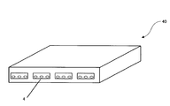
- FIG. 6 is a perspective view of the network device 30, and
- FIG. 7 is a perspective view of the broadcast video device 40.
- the option slot section 6 has input terminals and slots.
- the projection display device 1 is connected to an image server or the like via an input terminal, receives image data from the image server or the like, and projects an image. Further, a new function is added to the projection display device 1 by inserting a substrate or the like into the slot of the option slot portion 6.
- FIG. 3 is an enlarged view of the operation panel unit 4.
- the operation panel unit 4 includes a panel body 7, a display unit 8 disposed on the panel body 7, a switch unit 20, and a cover 15.
- the display unit 8 displays the state of the projection display device 1 (see FIGS. 1 and 2), the contents of commands, and the like.
- the panel body 7 is provided with a plurality of switches 9.
- a push button type switch is used as the switch 9, and the user can change the operation state of the projection display device 1 by pressing the switch 9.
- Some of the plurality of switches 9 constitute an adjustment switch group 10, and the rest of the plurality of switches 9 constitute an input switching switch group 11.
- the switch 9 is not limited to a push button type switch, and may be a volume knob, for example. In short, what is necessary is just to play the operation.
- a group composed of the adjustment switch group 10, the input switching switch group 11, and the label 12 is referred to as a switch unit 20.
- the operation panel unit 4 further includes a light source 13 and a reflection unit 14 including a reflection surface that reflects light emitted from the light source 13.
- 4 is a cross-sectional view of the operation panel section 4 taken along the II plane shown in FIG. 4 indicates an outline of the area A1 where light emitted from the light source 13 travels and an outline of the area A2 where light reflected by the reflecting surface of the reflecting member 14 travels.
- the light source 13 is disposed at the upper end of the operation panel unit 4 and generates light that illuminates the switch unit 20.
- the light source 13 illuminates the plurality of switches 9 of the switch unit 20, shadows of the plurality of switches 9 are formed on the panel body 7.
- the light source 13 is hidden using the cover 15, in FIG. 2 and FIG. 3, the light source 13 is shown so that the position of the light source 13 can be understood.
- the light from the light source 13 illuminates the switch unit 20, the light is less likely to enter the user's eyes directly. As a result, in an operation in a dark place, it is possible to prevent a decrease in visibility due to light entering the eyes directly.
- the light source 13 emits light along the panel body 7. More preferably, the chief ray of light emitted from the light source 13 is parallel to the surface of the panel body 7.
- the light emitted from the light source 13 travels along the panel body 7 from the upper side to the lower side of the operation panel unit 4, the light does not enter the user's eyes directly. As a result, in an operation in a dark place, it is possible to more reliably prevent a decrease in visibility due to direct light entering the eye.
- the light source 13 emits light along the panel body 7. More specifically, the principal ray of light emitted from the light source 13 is parallel to the surface of the panel body 7. When the light emitted from the light source 13 travels along the panel body 7 from the upper side to the lower side of the operation panel unit 4, the light does not enter the user's eyes directly. As a result, in an operation in a dark place, it is possible to prevent a decrease in visibility due to light entering the eyes directly.
- the reflection part 14 is provided on the panel body 7 so that the reflection surface thereof faces the light source 13 with the plurality of switches 9 interposed therebetween. Therefore, the light emitted from the light source 13 is reflected by the reflecting surface of the reflecting portion 14 and illuminates the plurality of switches 9. That is, the light reflected by the reflecting portion 14 illuminates a region of the panel body 7 opposite to the side where the light source 13 is disposed with respect to the switch 9. As a result, the shadow formed by the switch 9 blocking the light from the light source 13 is eliminated or thinned.
- FIG. 5 is a sectional view of such an operation panel. 5 indicates the outline of the area A1 where the light emitted from the light source 13 travels. In the area surrounded by the two-dot chain line and provided with dots, the switch 9 blocks the light from the light source 13. The shadow S formed by That is, as shown in FIG. 5, in the operation panel unit 16 that does not include a member corresponding to the reflection unit 14, the shadow formed by the switch 9 blocking the light from the light source 13 remains on the panel body 7.
- the label 12 is arranged in the area where the shadow of the switch 9 is formed, and the visibility of the label 12 is lowered.
- the label 12 is further away from the light source 13 than the adjustment switch group 10. Therefore, the illuminance by the light of the light source 13 in the label 12 is lower, and the label 12 is difficult to see.
- the light reflected by the reflecting portion 14 illuminates the shadow by the switch 9 and its vicinity. Since the shadow becomes lighter or disappears, the user can clearly see the entire operation panel unit 16.
- the user may check the label 12 because the light from the reflecting portion 14 illuminates the label 12. it can. As a result, the operability and visibility of the operation panel unit 4 are improved.
- the light source 13 is, for example, a semiconductor light emitting element such as an LED (Light Emitting Diode), an incandescent bulb, or a fluorescent lamp.
- a semiconductor light emitting element such as an LED (Light Emitting Diode), an incandescent bulb, or a fluorescent lamp.
Landscapes
- Push-Button Switches (AREA)
Abstract
製造コストの増加を招くことなくより高い操作性を有する電子機器を提供する。 スイッチ部(20)が設けられた操作パネル部(4)を有する電子機器(1)は、光源(13)と、反射部(14)と、を有する。光源(13)は操作パネル部(4)の端部に設置されており、スイッチ部(20)を照らす光を発する。反射部(14)は、光源(13)からの光を反射する反射面を有する。そして、反射部(14)は、スイッチ部(20)を挟んで光源(13)と対向するように設けられている。
Description
本発明は、スイッチなどを有する操作パネルを備えた電子機器に関する。
一般に、使用者は電子機器の操作パネルのスイッチを操作し、その電子機器を使用する。電子機器の一つとして、例えば、画像を投写する投写型表示装置が知られている。投写型表示装置は操作パネルを備えており、ユーザは操作パネルのスイッチを操作することで投写型表示装置の動作状態を切り替えることができる。
ところで、投写型表示装置は暗所で使用されることがある。投写型表示装置が暗所で使用される場合、操作パネルに光が当たらないためユーザは操作パネルのスイッチの位置を把握することができない。したがって、ユーザが操作パネルを操作しにくいという問題があった。このような問題点を解決する技術が特開2003-187665号公報(以下、「特許文献1」と称す)に開示されている。
特許文献1に開示の操作パネルは、パネル本体と、パネル本体に実装されたスイッチと、当該スイッチの近傍に配置された複数の光源と、を備える。複数の光源から発せられた光がスイッチの位置を示すため、スイッチの位置が容易に把握される。その結果、操作パネルの操作性が向上する。
しかしながら、複数のスイッチを備える操作パネルに特許文献1に開示の技術を適用すると次のような問題が生じる。
すなわち、特許文献1に開示の技術では1つのスイッチに対して複数の光源が必要とされる。したがって、スイッチの数の増加に伴って光源の数が増加する。その結果、操作パネルの製造コストが増加してしまうという問題があった。また、照明光が直接、目に入るので問題であった。
本発明の目的の一例は、製造コストの増加を招くことなくより高い操作性を有する操作パネルを有した電子機器を提供することにある。
本発明の一つの態様は、スイッチ部が設けられた操作パネル部を有する電子機器に係る。この態様において、光源と、反射部と、を有する。光源は操作パネル部の端部に設置されており、スイッチ部を照らす光を発する。反射部は光源からの光を反射する反射面を有する。そして、反射部はスイッチ部を挟んで光源と対向するように設けられている。
本発明によれば、製造コストの増加を招くことなく操作性がより高まる。
次に、本発明の実施形態例について、図面を参照して説明する。
図1は本実施形態例に係る電子機器の斜視図である。図2は図1に示される電子機器の側面図である。図1および2は電子機器として投写型表示装置が示されている。投写型表示装置は本発明の実施形態例の一つとして挙げたものであって、本発明は投写型表示装置に限定されない。例えば、本発明は、図6,7に示すように、ネットワーク機器や放送映像機器などであってもよい。図6はネットワーク機器30の斜視図であり、図7は放送映像機器40の斜視図である。
図1,2に示されるように、投写型表示装置1は、正面に開口を有する筐体2と、当該開口に配置された投写レンズ3と、筐体2の側面に配置された操作パネル部4と、を備えている。また、筐体2の側面には、吸気口5およびオプションスロット部6が形成されている。
オプションスロット部6は入力端子やスロットを有する。投写型表示装置1は入力端子を介して画像サーバー等に接続され、その画像サーバー等から画像データを受け取って画像を投写する。また、オプションスロット部6のスロットに基板等を挿入することで投写型表示装置1に新たな機能が追加される。
図3は、操作パネル部4の拡大図である。図3に示されるように、操作パネル部4は、パネル本体7と、パネル本体7に配された表示部8と、スイッチ部20と、カバー15と、を備える。表示部8は、投写型表示装置1(図1,2参照)の状態やコマンドの内容などを表示する。
パネル本体7には複数のスイッチ9が設けられている。本実施形態例ではスイッチ9として押しボタン型スイッチが用いられており、ユーザはスイッチ9を押すことで投写型表示装置1の動作状態を変えることができる。複数のスイッチ9のうちのいくつかは調整用スイッチ群10を構成しており、複数のスイッチ9のうちの残りは入力切り替え用スイッチ群11を構成している。スイッチ9は押しボタン型スイッチに限定されず、例えば、ボリュームのツマミであってもよい。要は、操作に奏するものであればよい。
調整用スイッチ群10を操作することで投写画像の画質や音量が調整される。入力切り替え用スイッチ群11を操作することで投写型表示装置1(図1,2参照)が投写する映像コンテンツが切り替えられる。入力切り替え用スイッチ群11を構成するスイッチ9の隣にはラベル12が配されている。ラベル12には、例えば投写型表示装置1が投写する映像コンテンツの名称などが記されている。
ここでは、調整用スイッチ群10と、入力切り替え用スイッチ群11と、ラベル12と、からなる一群をスイッチ部20と称する。
また、操作パネル部4は、光源13と、光源13から発せられた光を反射する反射面を含む反射部14と、をさらに備える。図4は図3に示されるI-I面で操作パネル部4を切断したときの断面図である。なお、図4中の一点鎖線は、光源13から発せられた光が進む領域A1の概略と、反射部材14の反射面で反射した光が進む領域A2の概略と、を示している。
図3および4に示されるように、光源13は操作パネル部4の上側の端部に配されており、スイッチ部20を照らす光を発生する。光源13から発せられる光がスイッチ部20の複数のスイッチ9を照らすと、複数のスイッチ9の影がパネル本体7に形成される。
なお、光源13はカバー15を用いて隠されているが、図2および図3では、光源13の位置が分かるように光源13が示されている。
光源13からの光はスイッチ部20を照らすため、当該光はユーザの眼に直接入りにくくなる。その結果、暗所での操作において、光が眼に直接入ることによる視認性の低下を防止することができる。
光源13は、パネル本体7に沿った光を発することがより好ましい。より好ましくは、光源13から発した光の主光線がパネル本体7の表面と平行になっている。光源13から発せられた光がパネル本体7に沿って操作パネル部4の上側から下側に向かって進むと、当該光がユーザの眼に直接入らなくなる。その結果、暗所での操作において、光が眼に直接入ることによる視認性の低下をより確実に防止することができる。
光源13は、パネル本体7に沿った光を発することがより好ましい。より詳しくは、光源13から発した光の主光線がパネル本体7の表面と平行になっている。光源13から発せられた光がパネル本体7に沿って操作パネル部4の上側から下側に向かって進むと、当該光がユーザの眼に直接入らなくなる。その結果、暗所での操作において、光が眼に直接入ることによる視認性の低下を防止することができる。
反射部14は、その反射面が複数のスイッチ9を挟んで光源13と対向するようにパネル本体7に設けられている。したがって、光源13から発せられた光は反射部14の反射面で反射して複数のスイッチ9を照らす。すなわち、反射部14において反射した光はパネル本体7の、スイッチ9に対して光源13が配された側とは反対側の領域を照らす。その結果、スイッチ9が光源13の光を遮ることで形成される影はなくなる、または薄くなる。
ところで、パネル本体の一端に光源を配置し、反射部4に相当する部材を備えていない操作パネルもある。このような操作パネルでは、1つの光源でより多くのスイッチが照らされるためその製造コストを抑制することができる。図5は、このような操作パネルの断面図を示したものである。図5中の一点鎖線は光源13から発せられた光が進む領域A1の概略を示しており、二点鎖線で囲まれかつドットが付された領域は、スイッチ9が光源13の光を遮ることで形成される影Sを示している。つまり、図5で示したように、反射部14に相当する部材を備えない操作パネル部16では、スイッチ9が光源13の光を遮ることで形成された影はパネル本体7上に残る。その結果、操作パネル部16の視認性が低下する。
図5に示される例では、スイッチ9の影が形成される領域にラベル12が配されており、ラベル12の視認性が低下する。特に、調整用スイッチ群10に比べ、ラベル12は光源13からより離されている。そのため、ラベル12における光源13の光による照度はより低く、ラベル12は見にくくなっている。
図5に示される例では、スイッチ9の影が形成される領域にラベル12が配されており、ラベル12の視認性が低下する。特に、調整用スイッチ群10に比べ、ラベル12は光源13からより離されている。そのため、ラベル12における光源13の光による照度はより低く、ラベル12は見にくくなっている。
操作パネル16やラベル12の視認性が低下すると、ユーザはラベル12を確認することができなくなる。その結果、操作パネル部16の操作性が低下する。
一方、図3,4に示されるように、本実施形態例では、反射部14によって反射された光は、スイッチ9による影およびその近傍を照らす。影が薄くなる、あるいは、影が消滅するので、ユーザは操作パネル部16の全体をはっきりと見ることができる。
特に、スイッチ9が光源13の光を遮ることで形成される影の領域にラベル12が配されていても、反射部14からの光がラベル12を照らすためユーザはラベル12を確認することができる。その結果、操作パネル部4の操作性および視認性が向上する。
また、本実施形態では、光源13の数は、スイッチ9の数よりも少なくてよい。したがって、スイッチ9の数が増えても光源13の数を増やす必要がなく、操作パネル4の製造コストが抑制される。図3および4に示される例では操作パネル部4は3つの光源13を備えているが、光源13の数は1つであってもよい。
反射部14はパネル本体7に対してスイッチ部20が設けられている面に傾斜していることがより好ましい。反射部14が傾斜していると反射部材14を用いて反射された光はパネル本体7へ向かう。その結果、反射部材14からのより多くの光がパネル本体7に照射され、パネル本体7がより明るくなる。
本実施形態例では、パネル本体7の法線と、反射部14との間の角度αを5度とした。もっとも、角度αは5度に限定されない。例えば、角度αは、2度から10度の範囲とすることができる。角度αが2度未満では、反射部14に近い領域を照明できないことがある。他方、角度αが10度よりも大きい場合には、パネル本体7の中央部の領域(光源13と反射部14との中間の領域)に照射できないことがある。
光源13は、例えばLED(Light Emitting Diode)などの半導体発光素子や白熱電球、蛍光ランプである。
反射部14は、例えば、アルミコートされたガラス板である。もちろん反射部14はアルミコートされたガラス板に限定されず、光源から発せられた光を反射する部材であればよい。
以上、実施例を参照して本願発明を説明したが、本願発明は上記実施例に限定されるものではない。本願発明の形や細部には、本願発明の技術思想の範囲内で当業者が理解し得る様々な変更をすることができる。
1 投写型表示装置
2 筐体
3 投写レンズ
4 操作パネル
5 吸気口
6 オプションスロット部
7 パネル本体
8 表示部
9 スイッチ
10 調整用スイッチ群
11 入力切り替え用スイッチ群
12 ラベル
13 光源
14 反射部
15 カバー
20 スイッチ部
2 筐体
3 投写レンズ
4 操作パネル
5 吸気口
6 オプションスロット部
7 パネル本体
8 表示部
9 スイッチ
10 調整用スイッチ群
11 入力切り替え用スイッチ群
12 ラベル
13 光源
14 反射部
15 カバー
20 スイッチ部
Claims (5)
- スイッチ部が設けられた操作パネル部を有する電子機器であって、
前記操作パネル部の端部に設置された、前記スイッチ部を照らす光を発生する光源と、
前記光源からの光を反射する反射面を有する反射部と、を有し、
前記反射部は、前記スイッチ部を挟んで前記光源と対向するように設けられている電子機器。 - 前記反射面は、前記操作パネル部の前記スイッチ部が設けられている面に向かって傾斜していることを特徴とする請求項1に記載の電子機器。
- 前記光源が発する光は、前記操作パネル部の前記スイッチ部が設けられている面に沿って進むことを特徴とする請求項1または2に記載の電子機器。
- 前記光源が発する光の主光線は、前記操作パネル部の前記スイッチ部が設けられている面と平行であることを特徴とする請求項3に記載の電子機器。
- 前記光源は半導体発光素子であることを特徴とする請求項1乃至4のいずれか1項に記載の電子機器。
Priority Applications (2)
| Application Number | Priority Date | Filing Date | Title |
|---|---|---|---|
| PCT/JP2012/077658 WO2014064820A1 (ja) | 2012-10-25 | 2012-10-25 | 電子機器 |
| CN201290001273.2U CN204348543U (zh) | 2012-10-25 | 2012-10-25 | 电子设备 |
Applications Claiming Priority (1)
| Application Number | Priority Date | Filing Date | Title |
|---|---|---|---|
| PCT/JP2012/077658 WO2014064820A1 (ja) | 2012-10-25 | 2012-10-25 | 電子機器 |
Publications (1)
| Publication Number | Publication Date |
|---|---|
| WO2014064820A1 true WO2014064820A1 (ja) | 2014-05-01 |
Family
ID=50544214
Family Applications (1)
| Application Number | Title | Priority Date | Filing Date |
|---|---|---|---|
| PCT/JP2012/077658 Ceased WO2014064820A1 (ja) | 2012-10-25 | 2012-10-25 | 電子機器 |
Country Status (2)
| Country | Link |
|---|---|
| CN (1) | CN204348543U (ja) |
| WO (1) | WO2014064820A1 (ja) |
Citations (3)
| Publication number | Priority date | Publication date | Assignee | Title |
|---|---|---|---|---|
| JPH0719901U (ja) * | 1993-09-17 | 1995-04-07 | エヌ・ティ・ティ・アドバンステクノロジ株式会社 | メモ機能付懐中電灯 |
| JPH0968049A (ja) * | 1995-09-04 | 1997-03-11 | Sawafuji Electric Co Ltd | エンジン発電機 |
| JP2003249990A (ja) * | 2002-02-25 | 2003-09-05 | Aiphone Co Ltd | インターホン玄関機構造 |
-
2012
- 2012-10-25 CN CN201290001273.2U patent/CN204348543U/zh not_active Expired - Lifetime
- 2012-10-25 WO PCT/JP2012/077658 patent/WO2014064820A1/ja not_active Ceased
Patent Citations (3)
| Publication number | Priority date | Publication date | Assignee | Title |
|---|---|---|---|---|
| JPH0719901U (ja) * | 1993-09-17 | 1995-04-07 | エヌ・ティ・ティ・アドバンステクノロジ株式会社 | メモ機能付懐中電灯 |
| JPH0968049A (ja) * | 1995-09-04 | 1997-03-11 | Sawafuji Electric Co Ltd | エンジン発電機 |
| JP2003249990A (ja) * | 2002-02-25 | 2003-09-05 | Aiphone Co Ltd | インターホン玄関機構造 |
Also Published As
| Publication number | Publication date |
|---|---|
| CN204348543U (zh) | 2015-05-20 |
Similar Documents
| Publication | Publication Date | Title |
|---|---|---|
| JP5051119B2 (ja) | 照明装置 | |
| KR20150008433A (ko) | 조명 디스플레이 스위칭 장치 | |
| US20110237300A1 (en) | Cellular phone | |
| JP5169806B2 (ja) | 照明装置 | |
| CN107110450B (zh) | 照明装置 | |
| EP2202547B1 (en) | Display device | |
| EP2577157B1 (en) | Ambient light device | |
| US20140286029A1 (en) | Lighting device for a vehicle interior | |
| CN101910917A (zh) | 液晶显示装置 | |
| WO2013069552A1 (ja) | 照明装置およびそれを備えた表示装置 | |
| US8602623B2 (en) | Electronic device and light-guiding structure thereof | |
| WO2014064820A1 (ja) | 電子機器 | |
| CN102034628B (zh) | 具有透光性的按键结构及其相关电子装置 | |
| US10295381B2 (en) | Indicator | |
| JP4577657B2 (ja) | 照明装置 | |
| CN111527008A (zh) | 车内照明灯 | |
| JP6329955B2 (ja) | 照明装置及び表示装置 | |
| JPWO2018131137A1 (ja) | 操作部構造およびこれを備えた電子機器 | |
| JP6009899B2 (ja) | 電子機器 | |
| TWM452383U (zh) | 觸控按鍵及圖標顯示裝置 | |
| JP7070027B2 (ja) | 表示装置 | |
| KR20090006653A (ko) | 전자기기의 디스플레이장치 | |
| JP2007194079A (ja) | 照明付スイッチ操作装置 | |
| TW200844365A (en) | Light emitting diode lamp | |
| CN101101436A (zh) | 图像显示装置 |
Legal Events
| Date | Code | Title | Description |
|---|---|---|---|
| WWE | Wipo information: entry into national phase |
Ref document number: 201290001273.2 Country of ref document: CN |
|
| 121 | Ep: the epo has been informed by wipo that ep was designated in this application |
Ref document number: 12886929 Country of ref document: EP Kind code of ref document: A1 |
|
| NENP | Non-entry into the national phase |
Ref country code: DE |
|
| 122 | Ep: pct application non-entry in european phase |
Ref document number: 12886929 Country of ref document: EP Kind code of ref document: A1 |
|
| NENP | Non-entry into the national phase |
Ref country code: JP |