WO2014054791A1 - 輸液針、および針抜け検知システム - Google Patents
輸液針、および針抜け検知システム Download PDFInfo
- Publication number
- WO2014054791A1 WO2014054791A1 PCT/JP2013/077109 JP2013077109W WO2014054791A1 WO 2014054791 A1 WO2014054791 A1 WO 2014054791A1 JP 2013077109 W JP2013077109 W JP 2013077109W WO 2014054791 A1 WO2014054791 A1 WO 2014054791A1
- Authority
- WO
- WIPO (PCT)
- Prior art keywords
- needle
- needle tube
- infusion
- pressure
- tube
- Prior art date
- Legal status (The legal status is an assumption and is not a legal conclusion. Google has not performed a legal analysis and makes no representation as to the accuracy of the status listed.)
- Ceased
Links
Images



Classifications
-
- A—HUMAN NECESSITIES
- A61—MEDICAL OR VETERINARY SCIENCE; HYGIENE
- A61M—DEVICES FOR INTRODUCING MEDIA INTO, OR ONTO, THE BODY; DEVICES FOR TRANSDUCING BODY MEDIA OR FOR TAKING MEDIA FROM THE BODY; DEVICES FOR PRODUCING OR ENDING SLEEP OR STUPOR
- A61M5/00—Devices for bringing media into the body in a subcutaneous, intra-vascular or intramuscular way; Accessories therefor, e.g. filling or cleaning devices, arm-rests
- A61M5/178—Syringes
- A61M5/31—Details
- A61M5/32—Needles; Details of needles pertaining to their connection with syringe or hub; Accessories for bringing the needle into, or holding the needle on, the body; Devices for protection of needles
- A61M5/329—Needles; Details of needles pertaining to their connection with syringe or hub; Accessories for bringing the needle into, or holding the needle on, the body; Devices for protection of needles characterised by features of the needle shaft
-
- A—HUMAN NECESSITIES
- A61—MEDICAL OR VETERINARY SCIENCE; HYGIENE
- A61B—DIAGNOSIS; SURGERY; IDENTIFICATION
- A61B5/00—Measuring for diagnostic purposes; Identification of persons
- A61B5/02—Detecting, measuring or recording for evaluating the cardiovascular system, e.g. pulse, heart rate, blood pressure or blood flow
- A61B5/021—Measuring pressure in heart or blood vessels
- A61B5/0215—Measuring pressure in heart or blood vessels by means inserted into the body
- A61B5/02152—Measuring pressure in heart or blood vessels by means inserted into the body specially adapted for venous pressure
-
- A—HUMAN NECESSITIES
- A61—MEDICAL OR VETERINARY SCIENCE; HYGIENE
- A61B—DIAGNOSIS; SURGERY; IDENTIFICATION
- A61B5/00—Measuring for diagnostic purposes; Identification of persons
- A61B5/68—Arrangements of detecting, measuring or recording means, e.g. sensors, in relation to patient
- A61B5/6846—Arrangements of detecting, measuring or recording means, e.g. sensors, in relation to patient specially adapted to be brought in contact with an internal body part, i.e. invasive
- A61B5/6847—Arrangements of detecting, measuring or recording means, e.g. sensors, in relation to patient specially adapted to be brought in contact with an internal body part, i.e. invasive mounted on an invasive device
- A61B5/6848—Needles
-
- A—HUMAN NECESSITIES
- A61—MEDICAL OR VETERINARY SCIENCE; HYGIENE
- A61M—DEVICES FOR INTRODUCING MEDIA INTO, OR ONTO, THE BODY; DEVICES FOR TRANSDUCING BODY MEDIA OR FOR TAKING MEDIA FROM THE BODY; DEVICES FOR PRODUCING OR ENDING SLEEP OR STUPOR
- A61M39/00—Tubes, tube connectors, tube couplings, valves, access sites or the like, specially adapted for medical use
- A61M39/10—Tube connectors; Tube couplings
- A61M39/105—Multi-channel connectors or couplings, e.g. for connecting multi-lumen tubes
-
- A—HUMAN NECESSITIES
- A61—MEDICAL OR VETERINARY SCIENCE; HYGIENE
- A61M—DEVICES FOR INTRODUCING MEDIA INTO, OR ONTO, THE BODY; DEVICES FOR TRANSDUCING BODY MEDIA OR FOR TAKING MEDIA FROM THE BODY; DEVICES FOR PRODUCING OR ENDING SLEEP OR STUPOR
- A61M5/00—Devices for bringing media into the body in a subcutaneous, intra-vascular or intramuscular way; Accessories therefor, e.g. filling or cleaning devices, arm-rests
- A61M5/178—Syringes
- A61M5/31—Details
- A61M5/32—Needles; Details of needles pertaining to their connection with syringe or hub; Accessories for bringing the needle into, or holding the needle on, the body; Devices for protection of needles
- A61M5/3295—Multiple needle devices, e.g. a plurality of needles arranged coaxially or in parallel
-
- A—HUMAN NECESSITIES
- A61—MEDICAL OR VETERINARY SCIENCE; HYGIENE
- A61M—DEVICES FOR INTRODUCING MEDIA INTO, OR ONTO, THE BODY; DEVICES FOR TRANSDUCING BODY MEDIA OR FOR TAKING MEDIA FROM THE BODY; DEVICES FOR PRODUCING OR ENDING SLEEP OR STUPOR
- A61M5/00—Devices for bringing media into the body in a subcutaneous, intra-vascular or intramuscular way; Accessories therefor, e.g. filling or cleaning devices, arm-rests
- A61M5/178—Syringes
- A61M5/31—Details
- A61M5/32—Needles; Details of needles pertaining to their connection with syringe or hub; Accessories for bringing the needle into, or holding the needle on, the body; Devices for protection of needles
- A61M5/3295—Multiple needle devices, e.g. a plurality of needles arranged coaxially or in parallel
- A61M5/3297—Needles arranged coaxially
-
- A—HUMAN NECESSITIES
- A61—MEDICAL OR VETERINARY SCIENCE; HYGIENE
- A61M—DEVICES FOR INTRODUCING MEDIA INTO, OR ONTO, THE BODY; DEVICES FOR TRANSDUCING BODY MEDIA OR FOR TAKING MEDIA FROM THE BODY; DEVICES FOR PRODUCING OR ENDING SLEEP OR STUPOR
- A61M39/00—Tubes, tube connectors, tube couplings, valves, access sites or the like, specially adapted for medical use
- A61M39/08—Tubes; Storage means specially adapted therefor
- A61M2039/082—Multi-lumen tubes
Definitions
- the present invention relates to an infusion needle that punctures a patient's blood vessel and allows a drug solution or the like to pass through, and a needle drop detection system.
- a method for injecting a drug solution into a blood vessel of a patient a method in which a catheter or an indwelling needle is placed in the blood vessel and a drug solution is injected from the tip is used.
- a catheter or an indwelling needle is placed in a vein, and the anticancer drug (or a drug solution diluted with the anticancer drug) is placed in the blood vessel. It is administered (injected).
- the present invention has been made in view of the circumstances described above, and an object of the present invention is to provide an infusion needle and a needle omission detection system that can reliably detect that the needle tip has come out of the blood vessel with a simple configuration. To do.
- the present invention has been proposed in order to achieve the above object, and the one according to claim 1 includes a tubular needle tube portion having an open front end portion.
- a needle tube passage through which the liquid can pass;
- the needle tube flow path is partitioned liquid-tightly, and a pressure transmission space capable of containing a pressure transmission medium capable of transmitting the pressure of the distal end portion to the proximal end side of the needle tube portion is formed. It is an infusion needle.
- the needle tube portion has a double tube structure in which the inner needle tube is inserted into the outer needle tube, and a circumferential surface is provided between the inner peripheral surface of the outer needle tube and the outer peripheral surface of the inner needle tube.
- a side space is formed, a needle core side space is formed in the inner needle tube, 2.
- a needle omission detection system comprising pressure detection means connected to a pressure transmission space of the infusion needle and capable of detecting the pressure transmitted by the pressure transmission medium.
- an infusion needle position determining means for determining whether or not the distal end portion of the needle tube portion is positioned in a blood vessel based on information on the pressure detected by the pressure detecting means,
- the infusion needle position determination means for determining whether or not the tip portion of the needle tube portion is located in the blood vessel based on the information on the pressure detected by the pressure detection means, Informing means for informing when the infusion needle position determining means determines that the distal end portion of the needle tube portion is not located in the blood vessel,
- a signal transmitting means for transmitting a signal when the infusion needle position determining means determines that the distal end portion of the needle tube portion is not located in the blood vessel, Signal receiving means for receiving a signal sent from the signal transmitting means, The needle dropout detection system according to claim 5, wherein the notification unit notifies based on a signal received by the signal reception unit.
- a tubular needle tube portion having an open front end portion is provided, and in the needle tube portion, a needle tube channel through which a liquid can pass and the needle tube channel are partitioned in a liquid-tight manner.
- a pressure transmission space in which a pressure transmission medium capable of transmitting the pressure of the distal end portion to the proximal end side of the needle tube portion is formed, so that the pressure around the distal end portion of the needle tube portion transmitted by the pressure transmission medium is formed
- the needle tube portion is configured by a double tube structure in which the inner needle tube is inserted into the outer needle tube, and between the inner peripheral surface of the outer needle tube and the outer peripheral surface of the inner needle tube.
- a peripheral surface side space is formed, a needle core side space is formed in the inner needle tube, and either the peripheral surface side space or the needle core side space is used as the needle tube flow path, and the other is used as the pressure transmission space. Therefore, the needle tube portion in which the needle tube flow path and the pressure transmission space are formed can be realized with a simple structure.
- the infusion needle according to claim 1 or 2 and the pressure transmission space connected to the pressure transmission space of the infusion needle and capable of detecting the pressure transmitted by the pressure transmission medium can be detected. Since the needle omission detection system is configured to include the pressure detection means, it can be reliably detected that the infusion needle is detached from the blood vessel.
- the infusion needle position determining means for determining whether or not the distal end portion of the needle tube portion is positioned in the blood vessel based on the information on the pressure detected by the pressure detecting means.
- An infusion stop means for stopping the infusion when the infusion needle position determining means determines that the distal end portion of the needle tube portion is not located in the blood vessel, so that the infusion needle is removed from the blood vessel. Can stop the infusion quickly.
- the infusion needle position determining means for determining whether or not the distal end portion of the needle tube portion is located in the blood vessel based on the information on the pressure detected by the pressure detecting means.
- an informing means for informing when it is determined that the distal end portion of the needle tube portion is not located in the blood vessel, so that the needle dropout detecting system is configured, so that it is easier to detect that the infusion needle has detached from the blood vessel. it can.
- the signal transmitting means transmits the signal
- the signal transmitting means And a signal receiving means for receiving a signal sent from the device, and constitutes a needle drop detection system, and the notification means notifies on the basis of the signal received by the signal receiving means, so that the patient who has punctured the infusion needle
- An informing means can be installed at a remote location, such as a nurse station, and it can be detected that the infusion needle has detached from the blood vessel even if the notification means is away from the patient.
- the infusion needle 1 is configured to include a tubular needle tube portion 3 having an open front end portion and a needle base portion 4 that is thicker than the needle tube portion 3.
- the needle tube portion 3 is formed of an elongated metal tube having a puncture portion 3a formed at the tip thereof, and a needle tube channel through which a liquid such as a drug solution or blood can pass, and the needle tube channel are liquid-tightly partitioned. And a pressure transmission space incapable of communication.
- the inner needle tube 6 is inserted into the outer needle tube 5 to form a double tube structure, and the outer needle tube 5 and the inner needle tube 6 are arranged on a concentric axis.
- the end portion extends from the proximal end of the outer needle tube 5 to the inside of the needle base portion 4.
- a cylindrical peripheral surface side space 8 that functions as a pressure transmission space is formed between the inner peripheral surface of the outer needle tube 5 and the outer peripheral surface of the inner needle tube 6.
- a needle core side space 9 functioning as a needle tube flow path is formed in the inside over the entire length of the inner needle tube 6, and the puncture portion 3a side of the needle core side space 9 is opened, and the peripheral surface side space 8 and the needle core side are opened.
- the space 9 extends along the axial direction of the needle tube portion 3.
- a communication opening 5a is formed in the outer peripheral surface of the outer needle tube 5 on the proximal end side, and a part of the space formed in the needle base 4 and the peripheral surface side space 8 are communicated with each other. It is comprised so that it may communicate via the opening 5a.
- the puncture part 3a side (left side in FIG. 3a) of the circumferential surface side space 8 is opened, and a pressure transmission medium (air in the present embodiment) 10 is contained in the circumferential surface side space 8, and the puncture part 3a It is configured such that outward pressure can be transmitted to the proximal end side (needle base 4 side) of the needle tube portion 3 via the pressure transmission medium 11.
- the peripheral surface side space 8 in the puncture portion 3a side 4 is covered with a flexible filter (not shown) to prevent blood from flowing into the peripheral surface side space 8, and the blood is shown in FIG. It is preferable that the pressure transmission medium 11 is configured to transmit the pressure outside the puncture portion 3a.
- the needle base 4 is a substantially y-shaped plastic member formed by integrally molding a base main body 13 coaxially with the needle tube 3 and a branching portion 14 branched from the base main body 13. It is connected to the base end side of the part 3.
- a tube connection space 17 for communicating a needle core side space (needle tube flow path) 9 with a tube 16 (see FIGS. 1 and 4) described later, and a circumferential surface side space (pressure transmission space). 8 is formed with a transmission side communication space 19 that communicates (connects) 8 to a control unit 18 (corresponding to pressure detecting means and infusion needle position determining means in the present invention) described later.
- the base body 13 has a cylindrical shape that is positioned coaxially with the needle tube portion 3, and a distal end portion 13 a that is positioned on the needle tube portion 3 side is connected to a base end portion 13 b of the base body 13 (right side portion in FIG. 2).
- the diameter is smaller than that.
- the proximal end portion of the outer needle tube 5 is inserted in a liquid-tight state on the central axis in the distal end portion 13 a, and the proximal end portion of the needle tube portion 3 is pushed into a step portion formed in the insertion space in the needle tube portion 3.
- the end part located in the needle tube part 3 in the peripheral surface side space 8 is closed.
- a base end portion protruding from the outer needle tube 5 of the inner needle tube 6 is inserted in a liquid-tight state on the central axis of the base end portion 13 b of the base body 13.
- a cylindrical tube connection space 17 is disposed on the opposite side of the proximal end portion 13b of the base portion main body 13 to the needle tube portion 3 (right side of the proximal end portion 13b in FIG. 3b) across the insertion end of the inner needle tube 6.
- the tube connection space 17 is opened toward the outside of the proximal end of the infusion needle 1 (on the right side in FIG. 3b), and the proximal end located in the needle base 4 in the needle core side space 9 Communicating to the side.
- the tube connection space 17 has a taper that gradually increases in diameter toward the opening, and a luer (not shown) provided at the tip of the tube 16 connected to the infusion needle 1 is fitted and connected.
- a luer taper structure is formed.
- a male screw portion 20 to which a lock ring 16 a attached to the end portion of the tube 16 can be screwed is formed at a position located on the open port side of the tube connection space 17 in the outer periphery of the base main body 13.
- the tube 16 and the base body 13 are in close contact with each other in a liquid-tight state, and the internal space of the tube 16 is reached. And the needle core side space 9 are configured to communicate with each other.
- the branch portion 14 has a cylindrical shape that branches from the side surface of the distal end portion 13 a of the base body 13 and protrudes toward the side of the base end portion 13 b of the base body 13, and is transmitted to the inside of the branch portion 14.
- the side communication space 19 is formed along the axial direction of the branch portion 14. Further, a portion of the transmission side communication space 19 located on the protruding end side of the branching portion 14 is opened outward, and an end opening on the base body 13 side is connected to the communication opening 5a of the outer needle tube 5, and the transmission side
- the communication space 19 and the circumferential surface side space 8 communicate with each other through the communication opening 5a.
- a pressure transmission medium (air in the present embodiment) 22 is provided inside the transmission side communication space 19, and the pressure transmitted from the pressure transmission medium 11 in the circumferential surface side space 8 is transmitted in the transmission side communication space 19.
- the pressure transmission medium 22 can be transmitted to the outside of the branch portion 14.
- the needle drop detection system 25 of the present embodiment includes the above-described infusion needle 1, tube 16, chemical solution bag 26, clamp 27 (corresponding to the infusion stop means in the present invention), pressure gauge 12, and control unit. 18, a pressure transmission tube 28, a pressure monitor 29, and a notification lamp 30 (corresponding to the notification means in the present invention), and the pressure outside the puncture portion 3 a is within the circumferential surface side space 8 and the transmission side communication space 19. It is transmitted by the pressure transmission media 11 and 22 and transmitted to the control unit 18.
- the drug solution bag 26 is a container for storing a drug solution such as an anticancer drug.
- the tube 16 has flexibility, one end is connected to the branch portion 14 of the infusion needle 1 and the other end is connected to the drug solution bag 26.
- the chemical solution in the chemical solution bag 26 can be introduced into the blood vessel 32 through the tube 16 and the needle core side space 9.
- a drip tube 31 is provided in the middle of the tube 16 so that the flow of the chemical solution can be visually confirmed.
- a clamp 27 is provided on the downstream side of the drip tube 31. The clamp 27 can adjust the flow rate of the chemical solution by pressing the tube 16 manually or by a signal from the control unit 18 or can stop the flow of the chemical solution.
- the pressure gauge 12 connects the branch portion 19 of the infusion needle 1 using a pressure transmission tube 28 containing a pressure transmission medium (air in this embodiment) 33, and the pressure transmission medium 11, 22, 33 connects the puncture portion 3 a.
- the pressure transmitted from the outside is measured.
- the control unit 18 has a function of acquiring the measured pressure value measured by the pressure gauge 12 and also functions as a control unit that controls driving of the clamp 27, the pressure monitor 29, and the notification lamp 30. Further, the control unit 18 determines whether or not the puncture unit 3a is located in the blood vessel 32 based on the pressure information measured by the control unit 18, and the puncture unit 3a is not located in the blood vessel 32. In this case, the driving signal is transmitted to the transmitter 35 (corresponding to the signal transmitting means in the present invention).
- This drive signal is transmitted (transmitted) by the transmitter 35 and is received by a receiver 36 (corresponding to the signal receiving means in the present invention) installed in a place away from the infusion needle 1, for example, a nurse station.
- the notification lamp 30 installed in the same place as the receiver 36 lights up and warns according to this drive signal.
- the driving signal may be transmitted and received by connecting the transmitter 35 and the receiver 36 with a cable or the like, or the transmitter 35 and the receiver 36 may not be connected with a cable or the like. May be transmitted / received (that is, transmission / reception of the drive signal may be wired or wireless).
- control part 18 controls the clamp 27, when the puncture part 3a is not located in the blood vessel 32, and stops the flow of the tube 16 so that a chemical
- the pressure monitor 29 receives a signal from the control unit 18 and displays information on the pressure measured by the control unit 18 at a constant time interval (for example, every 0.1 second).
- the infusion needle 1 is punctured into the blood vessel 32 of the patient.
- One end of the tube 16 whose other end is connected to the chemical solution bag 26 is connected in advance to the base body 13 and air in the tube 16 and the needle core side space 9 is excluded.
- the injection of the chemical solution into the blood vessel 32 is started, and the measurement of the pressure transmitted through the infusion needle 1 is started.
- the pressure in the blood vessel 32 is measured by the control unit 18.
- the puncture portion 3 a is detached from the blood vessel 32 and is located in a body tissue (for example, subcutaneous tissue) 38 other than the blood vessel 32
- the pressure in the body tissue 38 is different from the pressure in the blood vessel 32.
- atmospheric pressure is detected.
- the pressure detected by the control unit 18 varies (changes) depending on the position of the puncture unit 3a, it is determined whether the puncture unit 3a is located in the blood vessel 32 and the drug solution is normally injected. Can be judged. That is, the pressure transmitted through the infusion needle 1 can be monitored, and the needle dropout of the infusion needle 1 can be detected by this change in pressure.
- the puncture unit 3a If the pressure measured by the control unit 18 changes from the pressure in the blood while the infusion needle 1 (puncture unit 3a) is placed in the blood vessel 32 and the medicinal solution is injected, the puncture unit 3a
- the control part 18 determines that it is not located in the blood vessel 32, for example, drives the notification lamp 30 installed in a nurse station or the like to notify the surroundings.
- the clamp 27 is controlled to stop the flow of the tube 16 so that the drug solution does not flow to the infusion needle 1 side. Further, since the pressure detected by the control unit 18 is displayed on the pressure monitor 29, it is easy to recognize that the pressure outside the puncture unit 3a has changed by checking the display on the pressure monitor 29. can do.
- the puncture unit 3 a is not located in the blood vessel 32.
- the present invention is not limited to the case where the needle omission is determined based on the absolute value of the pressure, and the needle occlusion may be determined based on a change in the pulsation pattern.
- the infusion needle 1 can transmit the pressure outside the puncture unit 3a to the control unit 18 by the pressure transmission media (air) 11, 22, 33, the pressure transmission media 11, 22, 33 transmit the pressure.
- the pressure transmission media 11, 22, 33 transmit the pressure.
- the needle tube portion 3 is configured by a double tube structure in which the inner needle tube 6 is inserted into the outer needle tube 5, and a pressure transmission space is provided between the inner peripheral surface of the outer needle tube 5 and the outer peripheral surface of the inner needle tube 6.
- the needle tube portion 3 in which the needle tube flow path and the pressure transmission space are formed can be easily formed. It can be realized with a simple structure.
- the needle dropout detection system 25 includes the pressure monitor 29 that displays information on the pressure transmitted from the outside of the distal end portion of the needle tube portion 3 by the pressure transmission mediums 11, 22, 33. A change in pressure outside the part can be easily recognized. Thereby, it can be easily detected that the infusion needle 1 is detached from the blood vessel 32. Furthermore, based on the pressure information transmitted from the infusion needle 1, the control unit 18 that determines whether or not the puncture unit 3 a is located in the blood vessel 32, and the puncture unit 3 a is not located in the blood vessel 32 Since the notification lamp 30 for notifying the user is provided, it is possible to more easily detect that the infusion needle 1 is detached from the blood vessel 32.
- control unit 18 includes a transmitter 35 that transmits a signal when it is determined that the control unit 18 is not located in the blood vessel 32, and a receiver 36 that receives a signal transmitted from the transmitter 35. Since the notification lamp 30 notifies on the basis of the signal received by the machine 36, even if the notification lamp 30 can be installed in a place away from the patient who has punctured the infusion needle 1, for example, a nurse station, etc. It can be detected that the infusion needle 1 is detached from the blood vessel 32. Furthermore, when the control unit 18 determines that the puncture unit 3a is not located in the blood vessel 32, the clamp 27 is controlled by the control unit 18 to stop the infusion. Infusion can be stopped.
- the flow of the tube 16 was controlled using the clamp 27, it is not restricted to this.
- the control unit 18 controls (stops) the infusion pump or the like to stop the flow of the drug solution in the tube 16.
- medical solution bag 26 to the blood vessel was shown in the said embodiment, it is not restricted to this.
- the infusion needle of the present invention can also be used when injecting blood from a transfusion bag into a blood vessel.
- the needle tube portion 3 is configured by an elongated metal tube, but is not limited thereto.
- a catheter or an indwelling needle in which a puncture portion is not formed and a needle tube portion is made of a flexible resin or the like can be used as the infusion needle of the present invention.
- the surrounding surface side space 8 was made into the pressure transmission space and the needle core side space 9 was made into the needle tube flow path, it is not limited to this, The surrounding surface side space is made into the needle tube flow path, and a needle core The side space may be a pressure transmission space.
- the present invention is not limited to this.
- the inner needle tube 6 is disposed on the inner peripheral surface of the outer needle tube 5. You may arrange
- the needle tube part 3 was comprised by the double tube structure which penetrated the inner needle tube 6 in the outer needle tube 5, this invention is not limited to this.
- the structure of the needle tube portion is not limited as long as the needle tube flow path and the pressure transmission space are formed inside.
- a partition wall may be arranged along the axial direction inside a single tube member, and the inside of the tube member may be divided into two, one space may be used as a needle tube flow path, and the other space may be used as a pressure transmission space.
- the pressure transmission space (peripheral surface side space 8) is opened at the tip of the needle tube portion 3, but the present invention is not limited to this.
- the pressure transmission space may be opened anywhere.
- the pressure transmission space (circumferential surface side space 8 ′) may be opened on the outer peripheral surface of the needle tube portion 3 ′.
- the opening 40 of the needle tube channel (needle core side space 9 ') and the opening 41 of the pressure transmission space (circumferential surface side space 8') can be separated.
- the pressure outside the tip portion of the needle tube portion 3 ′ is stabilized without being affected by the pressure of the liquid flowing out from the needle tube flow path. And easy to detect.
- air is used as the pressure transmission medium, but the present invention is not limited to this.
- any material can be used as long as it can transmit the pressure outside the tip of the needle tube, and any gas or liquid other than air can be used as a pressure transmission medium as long as it does not adversely affect the patient receiving the infusion. May be adopted.
- reporting lamp was used as an alerting
- an alarm device that sounds an alarm sound may be used.
- the needle drop detection system 25 includes both the pressure monitor 29 and the notification lamp 30, but a configuration including at least one of them may be employed.
- a flat protrusion (a so-called “blade”) may be projected from the side of the infusion needle.
Landscapes
- Health & Medical Sciences (AREA)
- Life Sciences & Earth Sciences (AREA)
- Heart & Thoracic Surgery (AREA)
- Public Health (AREA)
- Biomedical Technology (AREA)
- Engineering & Computer Science (AREA)
- Animal Behavior & Ethology (AREA)
- General Health & Medical Sciences (AREA)
- Veterinary Medicine (AREA)
- Anesthesiology (AREA)
- Hematology (AREA)
- Vascular Medicine (AREA)
- Medical Informatics (AREA)
- Physics & Mathematics (AREA)
- Biophysics (AREA)
- Pathology (AREA)
- Molecular Biology (AREA)
- Surgery (AREA)
- Cardiology (AREA)
- Pulmonology (AREA)
- Physiology (AREA)
- Infusion, Injection, And Reservoir Apparatuses (AREA)
Abstract
輸液針1は、先端部分が開口した管状の針管部3を備えて構成されており、該針管部3内には、液が通過可能な針管流路として機能する針芯側空間9と、該針芯側空間9とは液密に区画され、前記針管部3の先端部分の圧力を針管部3の基端側へ伝達可能な圧力伝達媒体11を内在可能な周面側空間8と、が形成されている。
Description
本発明は、患者の血管に穿刺して、薬液等を通す輸液針、および針抜け検知システムに関する。
患者の血管内に薬液を注入する方法としては、カテーテルや留置針を血管内に留置して、先端から薬液を注入する方法が用いられている。例えば、がん治療の一種として抗がん剤を用いた化学療法では、カテーテルや留置針を静脈の血管内に留置して、抗がん剤(あるいは抗がん剤を希釈した薬液)を血管内に投与(注入)している。
しかしながら、抗がん剤等の薬液には、がん細胞のみならず正常な細胞に損傷を与えるものがある。このような薬液を投与する際に、誤って留置針等が血管外に外れると、血管外の体組織に薬液が漏出し、この状態を放置しておくと、薬液が漏出した部分の細胞に損傷を与える虞があった。そこで、留置針が血管外へ外れたことを検知する種々の方法が提案されている。例えば、留置針の先端からノイズ音を発生させ、留置針を穿刺した皮膚の近傍に貼り付けられた受信部によってノイズ音の有無を検知して、留置針が血管外へ外れたことを判断する構成が提案されている(例えば、特許文献1参照)。また、留置針の先端付近に磁性部を設け、留置針を穿刺した皮膚の近傍に貼り付けられた磁気センサーによって磁性部の磁束密度の変化を検知して、留置針が血管外へ外れたことを判断する構成が提案されている(例えば、特許文献2参照)。
ところで、上記した特許文献1または特許文献2に記載の構成では、留置針のほかノイズ発生器とノイズ受信器、磁気発生器と磁気センサー等が必要になるため、構成が複雑になっていた。また、血管に薬液を注入する際に、留置針を穿刺した後でノイズ受信器等を皮膚に貼り付ける必要があり、作業が複雑になっていた。さらに、受信部等の貼り付け位置がずれると、正確にノイズ音等を受信できず、留置針が血管外へ外れたことを検知できない虞があった。
本発明は、上記した事情に鑑みてなされたものであり、その目的は、簡単な構成で針先が血管外へ外れたことを確実に検知できる輸液針、および針抜け検知システムを提供しようとするものである。
本発明は、上記目的を達成するために提案されたものであり、請求項1に記載のものは、先端部分が開口した管状の針管部を備え、
該針管部内には、
液が通過可能な針管流路と、
該針管流路とは液密に区画され、前記先端部分の圧力を針管部の基端側へ伝達可能な圧力伝達媒体を内在可能な圧力伝達空間と、が形成されていることを特徴とする輸液針である。
該針管部内には、
液が通過可能な針管流路と、
該針管流路とは液密に区画され、前記先端部分の圧力を針管部の基端側へ伝達可能な圧力伝達媒体を内在可能な圧力伝達空間と、が形成されていることを特徴とする輸液針である。
請求項2に記載のものは、前記針管部は、外針管内に内針管を挿通した二重管構造で構成され、外針管の内周面と内針管の外周面との間には周面側空間を形成し、内針管内には針芯側空間を形成し、
前記周面側空間または針芯側空間のいずれか一方を前記針管流路とし、他方を前記圧力伝達空間としたことを特徴とする請求項1に記載の輸液針である。
前記周面側空間または針芯側空間のいずれか一方を前記針管流路とし、他方を前記圧力伝達空間としたことを特徴とする請求項1に記載の輸液針である。
請求項3に記載のものは、請求項1または請求項2に記載の輸液針と、
該輸液針の圧力伝達空間に接続され、前記圧力伝達媒体により伝達された前記圧力を検知可能な圧力検知手段と、を備えたことを特徴とする針抜け検知システムである。
該輸液針の圧力伝達空間に接続され、前記圧力伝達媒体により伝達された前記圧力を検知可能な圧力検知手段と、を備えたことを特徴とする針抜け検知システムである。
請求項4に記載のものは、前記圧力検知手段により検知された圧力の情報に基づいて、前記針管部の先端部分が血管内に位置するか否かを判定する輸液針位置判定手段と、
前記針管部の先端部分が血管内に位置していないと前記輸液針位置判定手段が判定した場合に輸液を停止する輸液停止手段と、を備えたことを特徴とする請求項3に記載の針抜け検知システムである。
前記針管部の先端部分が血管内に位置していないと前記輸液針位置判定手段が判定した場合に輸液を停止する輸液停止手段と、を備えたことを特徴とする請求項3に記載の針抜け検知システムである。
請求項5に記載のものは、前記圧力検知手段により検知された圧力の情報に基づいて、前記針管部の先端部分が血管内に位置するか否かを判定する輸液針位置判定手段と、
前記針管部の先端部分が血管内に位置していないと前記輸液針位置判定手段が判定した場合に報知する報知手段と、
を備えたことを特徴とする請求項3に記載の針抜け検知システムである。
前記針管部の先端部分が血管内に位置していないと前記輸液針位置判定手段が判定した場合に報知する報知手段と、
を備えたことを特徴とする請求項3に記載の針抜け検知システムである。
請求項6に記載のものは、前記針管部の先端部分が血管内に位置していないと前記輸液針位置判定手段が判定した場合に信号を送信する信号送信手段と、
該信号送信手段から送られてきた信号を受信する信号受信手段と、を備え、
該信号受信手段が受信した信号に基づいて前記報知手段が報知することを特徴とする請求項5に記載の針抜け検知システムである。
該信号送信手段から送られてきた信号を受信する信号受信手段と、を備え、
該信号受信手段が受信した信号に基づいて前記報知手段が報知することを特徴とする請求項5に記載の針抜け検知システムである。
本発明によれば、以下のような優れた効果を奏する。
請求項1に記載の発明によれば、先端部分が開口した管状の針管部を備え、該針管部内には、液が通過可能な針管流路と、該針管流路とは液密に区画され、前記先端部分の圧力を針管部の基端側へ伝達可能な圧力伝達媒体を内在可能な圧力伝達空間と、が形成されているので、圧力伝達媒体が伝達した針管部の先端部分周辺の圧力の変化を検知することで、輸液針が血管から外れたことを確実に検知できる。また、輸液針ユニットの外に別途受信部等の構成を設ける必要がなく、構成を簡単にすることができる。これにより、製造コストの低減を図ることができる。
請求項1に記載の発明によれば、先端部分が開口した管状の針管部を備え、該針管部内には、液が通過可能な針管流路と、該針管流路とは液密に区画され、前記先端部分の圧力を針管部の基端側へ伝達可能な圧力伝達媒体を内在可能な圧力伝達空間と、が形成されているので、圧力伝達媒体が伝達した針管部の先端部分周辺の圧力の変化を検知することで、輸液針が血管から外れたことを確実に検知できる。また、輸液針ユニットの外に別途受信部等の構成を設ける必要がなく、構成を簡単にすることができる。これにより、製造コストの低減を図ることができる。
請求項2に記載の発明によれば、前記針管部は、外針管内に内針管を挿通した二重管構造で構成され、外針管の内周面と内針管の外周面との間には周面側空間を形成し、内針管内には針芯側空間を形成し、前記周面側空間または針芯側空間のいずれか一方を前記針管流路とし、他方を前記圧力伝達空間としたので、針管流路と圧力伝達空間とが形成された針管部を簡単な構造で実現することができる。
請求項3に記載の発明によれば、請求項1または請求項2に記載の輸液針と、該輸液針の圧力伝達空間に接続され、前記圧力伝達媒体により伝達された前記圧力を検知可能な圧力検知手段と、を備えて針抜け検知システムを構成したので、輸液針が血管から外れたことを確実に検知できる。
請求項4に記載の発明によれば、前記圧力検知手段により検知された圧力の情報に基づいて、前記針管部の先端部分が血管内に位置するか否かを判定する輸液針位置判定手段と、前記針管部の先端部分が血管内に位置していないと前記輸液針位置判定手段が判定した場合に輸液を停止する輸液停止手段と、を備えたので、輸液針が血管から外れた場合には迅速に輸液を停止することができる。
請求項5に記載の発明によれば、前記圧力検知手段により検知された圧力の情報に基づいて、前記針管部の先端部分が血管内に位置するか否かを判定する輸液針位置判定手段と、前記針管部の先端部分が血管内に位置しないと判定された場合に報知する報知手段と、を備えて針抜け検知システムを構成したので、輸液針が血管から外れたことを一層容易に検知できる。
請求項6に記載の発明によれば、前記針管部の先端部分が血管内に位置していないと前記輸液針位置判定手段が判定した場合に信号を送信する信号送信手段と、該信号送信手段から送られてきた信号を受信する信号受信手段と、を備えて針抜け検知システムを構成し、信号受信手段が受信した信号に基づいて前記報知手段が報知するので、輸液針を穿刺した患者から離れた場所、例えばナースステーション等に報知手段を設置でき、患者から離れた場所にいたとしても輸液針が血管から外れたことを検知できる。
以下、本発明を実施するための形態を図面に基づいて説明する。
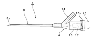
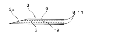
輸液針1は、図1および図2に示すように、先端部分が開口した管状の針管部3と、該針管部3よりも太い針基部4とを備えて構成されている。針管部3は、先端に穿刺部3aが形成された細長い金属管で構成され、内側に薬液や血液などの液が通過可能な針管流路と、該針管流路とは液密に区画されて連通不能な圧力伝達空間とを形成している。具体的に説明すると、外針管5の内部に内針管6を挿通して二重管構造で構成されており、外針管5と内針管6とを同心軸上に配置し、内針管6の基端部を外針管5の基端よりも針基部4の内側へ延ばしている。また、図3に示すように、外針管5の内周面と内針管6の外周面との間には、圧力伝達空間として機能する円筒状の周面側空間8を形成し、内針管6内には針管流路として機能する針芯側空間9を内針管6の全長に亘って形成するとともに当該針芯側空間9の穿刺部3a側を開放し、周面側空間8および針芯側空間9を針管部3の軸方向に沿って延在させている。
輸液針1は、図1および図2に示すように、先端部分が開口した管状の針管部3と、該針管部3よりも太い針基部4とを備えて構成されている。針管部3は、先端に穿刺部3aが形成された細長い金属管で構成され、内側に薬液や血液などの液が通過可能な針管流路と、該針管流路とは液密に区画されて連通不能な圧力伝達空間とを形成している。具体的に説明すると、外針管5の内部に内針管6を挿通して二重管構造で構成されており、外針管5と内針管6とを同心軸上に配置し、内針管6の基端部を外針管5の基端よりも針基部4の内側へ延ばしている。また、図3に示すように、外針管5の内周面と内針管6の外周面との間には、圧力伝達空間として機能する円筒状の周面側空間8を形成し、内針管6内には針管流路として機能する針芯側空間9を内針管6の全長に亘って形成するとともに当該針芯側空間9の穿刺部3a側を開放し、周面側空間8および針芯側空間9を針管部3の軸方向に沿って延在させている。
さらに、図3bに示すように、外針管5の基端部側の外周面には連通開口5aを開設し、針基部4内に形成される空間の一部と周面側空間8とを連通開口5aを介して連通するように構成されている。そして、周面側空間8の穿刺部3a側(図3a中、左側)を開放し、周面側空間8内には圧力伝達媒体(本実施形態では空気)10を内在させ、穿刺部3aの外方の圧力が圧力伝達媒体11を介して針管部3の基端側(針基部4側)へ伝達され得るように構成されている。なお、針管部3の先端部分を血管内に挿入した状態で、血液が周面側空間8内に穿刺部3a側から流入する虞がある場合には、周面側空間8の穿刺部3a側の開放部を可撓性のあるフィルター(図示せず)で覆う等して、血液の周面側空間8内への流入を阻止して血液が図4に示す後述の圧力計12(本発明における圧力検知手段に相当)に到達しないようにするとともに、穿刺部3aの外方の圧力が圧力伝達媒体11に伝達されるように構成することが好ましい。
針基部4は、針管部3と同軸上に位置する基部本体13と、該基部本体13から分岐した分岐部14とを一体成型して構成された略y字状のプラスチック製部材であり、針管部3の基端側に接続されている。そして、針基部4内には、針芯側空間(針管流路)9を後述のチューブ16(図1および図4参照)へ連通させるチューブ接続空間17と、周面側空間(圧力伝達空間)8を後述の制御部18(本発明における圧力検知手段、輸液針位置判定手段に相当)へ連通(接続)させる伝達側連通空間19とを形成している。
基部本体13は、針管部3と同軸上に位置する円筒状を呈しており、針管部3側に位置する先端部13aを、当該基部本体13の基端部13b(図2中、右側部)よりも縮径している。また、先端部13a内の中心軸上には外針管5の基端部を液密状態で挿入し、針管部3の基端部を針管部3内の挿入空間に形成された段差部に突き当てて、周面側空間8のうち針管部3内に位置する端部を閉塞している。さらに、基部本体13の基端部13bの中心軸上には、内針管6のうち外針管5から突出した基端部を液密状態で挿入している。そして、基部本体13の基端部13bのうち内針管6の挿入端を挟んで針管部3とは反対側(図3b中、基端部13bの右側)には、円筒状のチューブ接続空間17を形成し、該チューブ接続空間17を輸液針1の基端の外方(図3b中、右側方)に向けて開放するとともに、針芯側空間9のうち針基部4内に位置する基端側へ連通させている。なお、チューブ接続空間17は、開放口側に向けて次第に拡径したテーパとなっており、輸液針1に接続されるチューブ16の先端に設けられたルアー(図示せず)を嵌めて接続するルアーテーパ構造を構成している。また、基部本体13の外周のうちチューブ接続空間17の開放口側に位置する箇所には、チューブ16の端部に装着されるロックリング16aが螺合可能なおねじ部20を形成している。そして、チューブ16の端部をチューブ接続空間17に嵌め込んでロックリング16aをおねじ部20へ螺合すると、チューブ16と基部本体13とが液密状態で密着して、チューブ16の内部空間と針芯側空間9とが連通するように構成されている。
分岐部14は、基部本体13の先端部13aの側面から分岐して基部本体13の基端部13bの側方へ向かって突出した円筒形状を呈しており、当該分岐部14の内部には伝達側連通空間19を分岐部14の軸方向に沿って形成している。また、該伝達側連通空間19のうち分岐部14の突出端側に位置する部分を外方へ開放し、基部本体13側の端部開口を外針管5の連通開口5aに接続し、伝達側連通空間19と周面側空間8とを連通開口5aを介して連通している。さらに、伝達側連通空間19の内部には圧力伝達媒体(本実施形態では空気)22を内在させ、周面側空間8内の圧力伝達媒体11から伝達される圧力を、伝達側連通空間19内の圧力伝達媒体22を通じて分岐部14の外方へ伝達できるように構成されている。
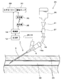
次に、針抜け検知システムについて、前述の輸液針1を用いて薬液を血液内に注入する場合を例に説明する。本実施形態の針抜け検知システム25は、図4に示すように、上記した輸液針1、チューブ16、薬液バッグ26、クランプ27(本発明における輸液停止手段に相当)、圧力計12、制御部18、圧力伝達チューブ28、圧力モニター29、および報知ランプ30(本発明における報知手段に相当)を備え、穿刺部3aの外方の圧力が周面側空間8内および伝達側連通空間19内の圧力伝達媒体11,22により伝達されて制御部18に伝達されることを特徴としている。薬液バッグ26は、抗がん剤等の薬液が貯留される容器である。チューブ16は、可撓性を有し、一端が輸液針1の分岐部14に接続されると共に、他端が薬液バッグ26に接続されている。これにより、薬液バッグ26内の薬液を、チューブ16および針芯側空間9を介して血管32内に導入することができる。また、チューブ16の途中には点滴筒31が設けられており、薬液の流れを目視で確認することができる。さらに、点滴筒31の下流側には、クランプ27が設けられている。クランプ27は、手動あるいは制御部18からの信号により、チューブ16を圧迫して薬液の流量を調節したり、薬液の流れを停止させたりすることができる。
圧力計12は、圧力伝達媒体(本実施形態では空気)33が内在する圧力伝達チューブ28を用いて輸液針1の分岐部19を接続し、圧力伝達媒体11,22,33により穿刺部3aの外方から伝達してきた圧力を測定するものである。また、制御部18は、圧力計12で測定された測定された圧力値を取得できる機能を備え、クランプ27、圧力モニター29、および報知ランプ30の駆動を制御する制御手段としても機能する。さらに、制御部18は、当該制御部18が測定した圧力の情報に基づいて、穿刺部3aが血管32内に位置するか否かを判定し、穿刺部3aが血管32内に位置していない場合に発信機35(本発明における信号送信手段に相当)へ駆動信号を送信するように構成されている。この駆動信号は、発信機35によって発信(送信)され、輸液針1から離れた場所、例えばナースステーション等に設置された受信機36(本発明における信号受信手段に相当)によって受信される。そして、受信機36と同じ場所に設置された報知ランプ30は、この駆動信号に応じて、点灯して警報する。なお、駆動信号は、発信機35と受信機36をケーブル等で接続して電気信号等を送受信するようにしてもよいし、発信機35と受信機36をケーブル等で接続せずに、電波を送受信するようにしてもよい(すなわち、駆動信号の送受信は有線でも無線でもよい)。さらに、制御部18は、穿刺部3aが血管32内に位置していない場合にクランプ27を制御して、薬液が輸液針1側へ流れないようにチューブ16の流れを停止させる。圧力モニター29は、制御部18からの信号を受信し、制御部18によって測定された圧力の情報を一定の時間間隔(例えば、0.1秒間隔)で表示する。
次に、上記した針抜け検知システム25による薬液の注入、および輸液針1の針先位置の検知(特に、針抜け検知)について説明する。まず、輸液針1を患者の血管32内に穿刺する。なお、他端が薬液バッグ26に接続されたチューブ16の一端を基部本体13に予め接続すると共に、チューブ16内および針芯側空間9内の空気を排除しておく。そして、血管32内への薬液の注入を開始すると共に、輸液針1を通じて伝達される圧力の測定を開始する。
ここで、穿刺部3aが血管32内に留置されている場合には、血管32内の圧力が制御部18で測定される。しかしながら、穿刺部3aが血管32外に外れ、血管32以外の体組織(例えば、皮下組織)38内に位置している場合には、血管32内の圧力とは異なる体組織38内の圧力が検出され、穿刺部3aが体外に完全に外れてしまった場合には、大気圧が検出される。このように、穿刺部3aの位置に応じて、制御部18で検出される圧力が異なる(変化する)ため、穿刺部3aが血管32内に位置し、薬液が正常に注入されているか否かを判断することができる。すなわち、輸液針1を通じて伝達される圧力を監視し、この圧力の変化により輸液針1の針抜けを検知することができる。
そして、輸液針1(穿刺部3a)を血管32内に留置し、薬液を注入している状態で、制御部18により測定される圧力が血液内の圧力から変化したならば、穿刺部3aが血管32内に位置していないと制御部18が判定し、例えばナースステーション等に設置された報知ランプ30を駆動して周囲に報知する。同時に、クランプ27を制御して、薬液が輸液針1側へ流れないようにチューブ16の流れを停止させる。また、制御部18により検出された圧力は、圧力モニター29に表示されているため、この圧力モニター29の表示を確認することで、穿刺部3aの外方の圧力が変化したことを容易に認識することができる。これにより、穿刺部3aが血管32内に位置していないと容易に判定することができる。なお、本発明は、圧力の絶対値により針抜けを判定する場合に限らず、脈動のパターンの変化により針抜けを判定してもよい。
このように、輸液針1は、穿刺部3aの外方の圧力を圧力伝達媒体(空気)11,22,33により制御部18へ伝達可能としたので、圧力伝達媒体11,22,33が伝達した穿刺部3a周辺の圧力の変化を検知することで、輸液針1が血管32から外れたことを確実に検知できる。また、輸液針1の外に別途受信部等の構成を設ける必要がなく、構成を簡単にすることができる。これにより、製造コストの低減を図ることができる。さらに、針管部3は、外針管5内に内針管6を挿通した二重管構造で構成され、外針管5の内周面と内針管6の外周面との間には、圧力伝達空間として機能する周面側空間8を形成し、内針管6内には針管流路として機能する針芯側空間9を形成したので、針管流路と圧力伝達空間とが形成された針管部3を簡単な構造で実現することができる。
また、針抜け検知システム25は、針管部3の先端部分の外方から圧力伝達媒体11,22,33により伝達された圧力の情報を表示する圧力モニター29を備えたので、針管部3の先端部分の外方における圧力の変化を容易に認識することができる。これにより、輸液針1が血管32から外れたことを容易に検知できる。さらに、輸液針1から伝達された圧力の情報に基づいて、穿刺部3aが血管32内に位置するか否かを判定する制御部18と、穿刺部3aが血管32内に位置していない場合に報知する報知ランプ30と、を備えたので、輸液針1が血管32から外れたことを一層容易に検知できる。加えて、制御部18が血管32内に位置していないと判定した場合に信号を送信する発信機35と、発信機35から送られてきた信号を受信する受信機36と、を備え、受信機36が受信した信号に基づいて報知ランプ30が報知するので、輸液針1を穿刺した患者から離れた場所、例えばナースステーション等に報知ランプ30を設置でき、患者から離れた場所にいたとしても輸液針1が血管32から外れたことを検知できる。さらに、穿刺部3aが血管32内に位置していないと制御部18が判定すると、クランプ27が制御部18により制御されて輸液を停止するので、輸液針1が血管から外れた場合には迅速に輸液を停止することができる。
ところで、上記実施形態では、クランプ27を用いてチューブ16の流れを制御したが、これには限られない。例えば、輸液ポンプ等を用いて、薬液バッグ26から輸液針1側に薬液を送るようにしてもよい。この場合において、穿刺部3aが血管32内に位置していない場合には、制御部18が輸液ポンプ等を制御(停止)して、チューブ16内の薬液の流れを停止させる。また、上記実施形態では、薬液バッグ26からの薬液を血管に注入する例を示したが、これには限られない。例えば、輸血バッグからの血液を血管に注入する際にも、本発明の輸液針を用いることができる。
また、上記実施形態の輸液針1では、針管部3を細長い金属管で構成したが、これには限られない。例えば、穿刺部が形成されておらず、針管部が可撓性を有する樹脂等で構成されたカテーテルまたは留置針を、本発明の輸液針として使用することもできる。さらに、上記実施形態では、周面側空間8を圧力伝達空間とし、針芯側空間9を針管流路としたが、これには限定されず、周面側空間を針管流路とし、針芯側空間を圧力伝達空間としてもよい。また、外針管5内と内針管6とを同心軸上に配置する場合を説明したが、本発明はこれに限定されるものではなく、例えば、内針管6を外針管5の内周面に当接するように配置してもよいし、内周面に一体成形してもよい。そして、外針管5内に内針管6を挿通した二重管構造で針管部3を構成したが、本発明はこれに限定されない。要は、内部に針管流路と圧力伝達空間とが形成されれば、針管部の構造は問わない。例えば、単一の管部材の内側に仕切壁が軸方向に沿って配置されて管部材の内部を二分し、一方の空間を針管流路とし、他方の空間を圧力伝達空間としてもよい。
また、上記実施形態では、針管部3の先端で圧力伝達空間(周面側空間8)を開放したが、本発明はこれに限定されない。要は、針管部3の先端部分の外方の圧力を圧力伝達空間内の圧力伝達媒体に伝えることができれば、圧力伝達空間の開放箇所はどこでもよい。例えば、図5に示すように、針管部3′の外周面で圧力伝達空間(周面側空間8′)を開放してもよい。このようにすれば、針管流路(針芯側空間9′)の開放口40と圧力伝達空間(周面側空間8′)の開放口41とを離間させることができる。これにより、針管部3′の先端部分の外方の圧力を検知する際に、針管流路から流出する液の圧力の影響を受け難く、針管部3′の先端部分の外方の圧力を安定して検出し易い。
ところで、上記実施形態では、圧力伝達媒体として空気を採用したが、本発明はこれに限定されない。要は、針管部の先端部分の外方の圧力を伝達可能な材料であれば、どのようなものでもよく、輸液を受ける患者に悪影響を及ぼさなければ、空気以外の気体や液体を圧力伝達媒体として採用してもよい。また、上記各実施形態では、報知手段として報知ランプを用いたが、本発明はこれに限定されない。例えば、警報音を鳴らす警報機等を用いてもよい。さらに、上記各実施形態では、針抜け検知システム25に圧力モニター29と報知ランプ30との両方を備えたが、少なくともいずれか一方を備えた構成であってもよい。また、本発明における輸液針を患者にテープで固定し易くするために、輸液針の側部から平板状の突出片(所謂「羽根」)を突設してもよい。
そして、前記した実施の形態は全ての点で例示であって制限的なものではないと考えられるべきである。本発明は、上記した説明に限らず特許請求の範囲によって示され、特許請求の範囲と均等の意味及び範囲内での全ての変更が含まれるものである。
1 輸液針
3,3′ 針管部
3a 穿刺部
4 針基部
5 外針管
5a 連通開口
6 内針管
8,8′ 周面側空間
9,9′ 針芯側空間
11 周面側空間内の圧力伝達媒体
12 圧力計
13 基部本体
13a 先端部
13b 基端部
14 分岐部
16 チューブ
16a ロックリング
17 チューブ接続空間
18 制御部
19 伝達側連通空間
20 おねじ部
22 伝達側連通空間内の圧力伝達媒体
25 針抜け検知システム
26 薬液バッグ
27 クランプ
28 圧力伝達チューブ
29 圧力モニター
30 報知ランプ
31 点滴筒
32 血管
33 圧力伝達チューブ内の圧力伝達媒体
35 発信機
36 受信機
38 体組織
40 針芯側空間の開放口
41 周面側空間の開放口
3,3′ 針管部
3a 穿刺部
4 針基部
5 外針管
5a 連通開口
6 内針管
8,8′ 周面側空間
9,9′ 針芯側空間
11 周面側空間内の圧力伝達媒体
12 圧力計
13 基部本体
13a 先端部
13b 基端部
14 分岐部
16 チューブ
16a ロックリング
17 チューブ接続空間
18 制御部
19 伝達側連通空間
20 おねじ部
22 伝達側連通空間内の圧力伝達媒体
25 針抜け検知システム
26 薬液バッグ
27 クランプ
28 圧力伝達チューブ
29 圧力モニター
30 報知ランプ
31 点滴筒
32 血管
33 圧力伝達チューブ内の圧力伝達媒体
35 発信機
36 受信機
38 体組織
40 針芯側空間の開放口
41 周面側空間の開放口
Claims (6)
- 先端部分が開口した管状の針管部を備え、
該針管部内には、
液が通過可能な針管流路と、
該針管流路とは液密に区画され、前記先端部分の圧力を針管部の基端側へ伝達可能な圧力伝達媒体を内在可能な圧力伝達空間と、が形成されていることを特徴とする輸液針。 - 前記針管部は、外針管内に内針管を挿通した二重管構造で構成され、外針管の内周面と内針管の外周面との間には周面側空間を形成し、内針管内には針芯側空間を形成し、
前記周面側空間または針芯側空間のいずれか一方を前記針管流路とし、他方を前記圧力伝達空間としたことを特徴とする請求項1に記載の輸液針。 - 請求項1または請求項2に記載の輸液針と、
該輸液針の圧力伝達空間に接続され、前記圧力伝達媒体により伝達された前記圧力を検知可能な圧力検知手段と、を備えたことを特徴とする針抜け検知システム。 - 前記圧力検知手段により検知された圧力の情報に基づいて、前記針管部の先端部分が血管内に位置するか否かを判定する輸液針位置判定手段と、
前記針管部の先端部分が血管内に位置していないと前記輸液針位置判定手段が判定した場合に輸液を停止する輸液停止手段と、を備えたことを特徴とする請求項3に記載の針抜け検知システム。 - 前記圧力検知手段により検知された圧力の情報に基づいて、前記針管部の先端部分が血管内に位置するか否かを判定する輸液針位置判定手段と、
前記針管部の先端部分が血管内に位置していないと前記輸液針位置判定手段が判定した場合に報知する報知手段と、
を備えたことを特徴とする請求項3に記載の針抜け検知システム。 - 前記針管部の先端部分が血管内に位置していないと前記輸液針位置判定手段が判定した場合に信号を送信する信号送信手段と、
該信号送信手段から送られてきた信号を受信する信号受信手段と、を備え、
該信号受信手段が受信した信号に基づいて前記報知手段が報知することを特徴とする請求項5に記載の針抜け検知システム。
Applications Claiming Priority (2)
| Application Number | Priority Date | Filing Date | Title |
|---|---|---|---|
| JP2012-222137 | 2012-10-04 | ||
| JP2012222137A JP5603915B2 (ja) | 2012-10-04 | 2012-10-04 | 輸液針、および針抜け検知システム |
Publications (1)
| Publication Number | Publication Date |
|---|---|
| WO2014054791A1 true WO2014054791A1 (ja) | 2014-04-10 |
Family
ID=50435109
Family Applications (1)
| Application Number | Title | Priority Date | Filing Date |
|---|---|---|---|
| PCT/JP2013/077109 Ceased WO2014054791A1 (ja) | 2012-10-04 | 2013-10-04 | 輸液針、および針抜け検知システム |
Country Status (2)
| Country | Link |
|---|---|
| JP (1) | JP5603915B2 (ja) |
| WO (1) | WO2014054791A1 (ja) |
Cited By (1)
| Publication number | Priority date | Publication date | Assignee | Title |
|---|---|---|---|---|
| ITUB20160798A1 (it) * | 2016-02-16 | 2017-08-16 | Fabio Nicola Arrizza | Dispositivo di rilevazione diretta della pressione intravascolare |
Families Citing this family (1)
| Publication number | Priority date | Publication date | Assignee | Title |
|---|---|---|---|---|
| JP6855028B1 (ja) * | 2020-11-13 | 2021-04-07 | 諸見里 和子 | 点滴注射キット |
Citations (6)
| Publication number | Priority date | Publication date | Assignee | Title |
|---|---|---|---|---|
| WO1999059463A1 (en) * | 1998-05-15 | 1999-11-25 | Respironics, Inc. | Monitoring catheter and method of using same |
| JP2001518808A (ja) * | 1995-06-07 | 2001-10-16 | ハートポート インコーポレイテッド | 心臓を停止させるための血管内システム |
| JP2003265613A (ja) * | 2002-03-15 | 2003-09-24 | Terumo Corp | 拡張体付きカテーテルの制御方法、採血制御装置および拡張体付きカテーテル |
| JP4290106B2 (ja) * | 2004-10-15 | 2009-07-01 | 日機装株式会社 | 血液浄化装置 |
| JP2010507455A (ja) * | 2006-10-24 | 2010-03-11 | カンヌフロウ インコーポレイテッド | 体液溢出防止カテーテル |
| WO2011022073A1 (en) * | 2009-08-19 | 2011-02-24 | Mirador Biomedical | Systems, methods, and devices for facilitating access to target anatomical sites or environments |
-
2012
- 2012-10-04 JP JP2012222137A patent/JP5603915B2/ja active Active
-
2013
- 2013-10-04 WO PCT/JP2013/077109 patent/WO2014054791A1/ja not_active Ceased
Patent Citations (6)
| Publication number | Priority date | Publication date | Assignee | Title |
|---|---|---|---|---|
| JP2001518808A (ja) * | 1995-06-07 | 2001-10-16 | ハートポート インコーポレイテッド | 心臓を停止させるための血管内システム |
| WO1999059463A1 (en) * | 1998-05-15 | 1999-11-25 | Respironics, Inc. | Monitoring catheter and method of using same |
| JP2003265613A (ja) * | 2002-03-15 | 2003-09-24 | Terumo Corp | 拡張体付きカテーテルの制御方法、採血制御装置および拡張体付きカテーテル |
| JP4290106B2 (ja) * | 2004-10-15 | 2009-07-01 | 日機装株式会社 | 血液浄化装置 |
| JP2010507455A (ja) * | 2006-10-24 | 2010-03-11 | カンヌフロウ インコーポレイテッド | 体液溢出防止カテーテル |
| WO2011022073A1 (en) * | 2009-08-19 | 2011-02-24 | Mirador Biomedical | Systems, methods, and devices for facilitating access to target anatomical sites or environments |
Cited By (3)
| Publication number | Priority date | Publication date | Assignee | Title |
|---|---|---|---|---|
| ITUB20160798A1 (it) * | 2016-02-16 | 2017-08-16 | Fabio Nicola Arrizza | Dispositivo di rilevazione diretta della pressione intravascolare |
| WO2017141183A1 (en) * | 2016-02-16 | 2017-08-24 | M.E.A. Pharma Sagl | Device for the direct detection of the endovascular pressure of a fluid in a vessel |
| US11185240B2 (en) | 2016-02-16 | 2021-11-30 | M.E.A. Pharma Sagl | Device for the direct detection of the endovascular pressure of a fluid in a vessel |
Also Published As
| Publication number | Publication date |
|---|---|
| JP2014073230A (ja) | 2014-04-24 |
| JP5603915B2 (ja) | 2014-10-08 |
Similar Documents
| Publication | Publication Date | Title |
|---|---|---|
| AU2020219832B2 (en) | System, method, and product for event monitoring | |
| KR102537181B1 (ko) | 환자 라인의 음향 주파수 인식 | |
| JP2019515718A (ja) | 光ファイバセンサ | |
| CN102355924A (zh) | 动脉回流确认室 | |
| CN102548606A (zh) | 转动型医用多路开关 | |
| US12276534B2 (en) | Priming valve to induce appropriate pressure and flow profile and improve sensor readiness | |
| JP5603915B2 (ja) | 輸液針、および針抜け検知システム | |
| JP6074211B2 (ja) | 輸液針、輸液針ユニット、輸液装置、および針抜け検知システム | |
| JP5571421B2 (ja) | 血管外漏出検知装置及び輸液装置 | |
| US9561319B2 (en) | Device and method for fixing a segment of tubing, for an arrangement for monitoring an access to a patient | |
| US20240123136A1 (en) | Multi-component communication system for infusion line identification | |
| JP2017086649A (ja) | 輸液針および針抜け検知システム | |
| JP5481246B2 (ja) | 血管外漏出検知装置及び輸液装置 | |
| CN212700025U (zh) | 一种带有报警功能的picc专用针 | |
| JP2017086651A (ja) | 輸液針および針抜け検知システム | |
| JP6855028B1 (ja) | 点滴注射キット | |
| JP2017086650A (ja) | 輸液針および針抜け検知システム | |
| CN206526346U (zh) | 留置针 | |
| KR102545496B1 (ko) | 압력센서를 내장하는 유체 토출장치 | |
| JP2011200430A (ja) | 血管外漏出検知装置及び輸液装置 | |
| CN121421687A (zh) | 一种具备导航与闭环给药功能的Ommaya囊智能管理装置 | |
| KR20190111378A (ko) | 혈관 내 도관기능 평가장치 | |
| HK1161158B (en) | Flow control valves for leakage detection, free-low prevention and occlusion detection | |
| HK1161158A1 (en) | Flow control valves for leakage detection, free-low prevention and occlusion detection |
Legal Events
| Date | Code | Title | Description |
|---|---|---|---|
| 121 | Ep: the epo has been informed by wipo that ep was designated in this application |
Ref document number: 13843286 Country of ref document: EP Kind code of ref document: A1 |
|
| DPE1 | Request for preliminary examination filed after expiration of 19th month from priority date (pct application filed from 20040101) | ||
| NENP | Non-entry into the national phase |
Ref country code: DE |
|
| 122 | Ep: pct application non-entry in european phase |
Ref document number: 13843286 Country of ref document: EP Kind code of ref document: A1 |