WO2014054486A1 - 熱交換器用アルミニウム合金フィン材およびその製造方法 - Google Patents
熱交換器用アルミニウム合金フィン材およびその製造方法 Download PDFInfo
- Publication number
- WO2014054486A1 WO2014054486A1 PCT/JP2013/075895 JP2013075895W WO2014054486A1 WO 2014054486 A1 WO2014054486 A1 WO 2014054486A1 JP 2013075895 W JP2013075895 W JP 2013075895W WO 2014054486 A1 WO2014054486 A1 WO 2014054486A1
- Authority
- WO
- WIPO (PCT)
- Prior art keywords
- fin material
- aluminum alloy
- less
- mass
- heat exchanger
- Prior art date
- Legal status (The legal status is an assumption and is not a legal conclusion. Google has not performed a legal analysis and makes no representation as to the accuracy of the status listed.)
- Ceased
Links
Classifications
-
- C—CHEMISTRY; METALLURGY
- C22—METALLURGY; FERROUS OR NON-FERROUS ALLOYS; TREATMENT OF ALLOYS OR NON-FERROUS METALS
- C22F—CHANGING THE PHYSICAL STRUCTURE OF NON-FERROUS METALS AND NON-FERROUS ALLOYS
- C22F1/00—Changing the physical structure of non-ferrous metals or alloys by heat treatment or by hot or cold working
- C22F1/04—Changing the physical structure of non-ferrous metals or alloys by heat treatment or by hot or cold working of aluminium or alloys based thereon
-
- B—PERFORMING OPERATIONS; TRANSPORTING
- B21—MECHANICAL METAL-WORKING WITHOUT ESSENTIALLY REMOVING MATERIAL; PUNCHING METAL
- B21B—ROLLING OF METAL
- B21B3/00—Rolling materials of special alloys so far as the composition of the alloy requires or permits special rolling methods or sequences ; Rolling of aluminium, copper, zinc or other non-ferrous metals
-
- C—CHEMISTRY; METALLURGY
- C22—METALLURGY; FERROUS OR NON-FERROUS ALLOYS; TREATMENT OF ALLOYS OR NON-FERROUS METALS
- C22C—ALLOYS
- C22C21/00—Alloys based on aluminium
-
- C—CHEMISTRY; METALLURGY
- C22—METALLURGY; FERROUS OR NON-FERROUS ALLOYS; TREATMENT OF ALLOYS OR NON-FERROUS METALS
- C22F—CHANGING THE PHYSICAL STRUCTURE OF NON-FERROUS METALS AND NON-FERROUS ALLOYS
- C22F1/00—Changing the physical structure of non-ferrous metals or alloys by heat treatment or by hot or cold working
Definitions
- This invention relates to the aluminum alloy fin material for heat exchangers used for a heat exchanger, and its manufacturing method.
- fin materials aluminum alloy fin materials for heat exchangers used in heat exchangers such as air conditioners (hereinafter referred to as fin materials as appropriate) have also been switched to new refrigerants in line with chlorofluorocarbon regulations, and the air conditioners themselves have become more compact and lightweight.
- the thickness has been further reduced, and the thickness has been reduced to 0.15 mm or less, and recently to about 0.09 mm.
- the draw method consists of an overhanging process, a drawing process, a punching (piercing) and hole expanding process (burring), and a flaring process. Is mainly composed of an overhanging process, a drawing process, a punching and hole expanding process, an ironing process, and a flaring process.
- the piercing & burring molding and the flaring molding for molding the tube hole collar in the copper pipe are indispensable molding processes for the fin material.
- these moldings are severe molding for the fin material whose thickness is reduced to 0.15 mm or less. Therefore, fin materials with improved workability have been developed in response to such thinning.
- the plate thickness is 0.15 mm or less, and the grain size of the intermetallic compound, the maximum length of the large tilt grain, the average grain size of the subcrystal grains in the large tilt grain, and the like are predetermined.
- a defined aluminum alloy fin material having excellent formability is disclosed.
- Patent Document 2 discloses that the plate thickness is less than 0.11 mm, contains a predetermined amount of Fe and Ti, regulates Si and Cu to be equal to or less than a predetermined amount, and prescribes a predetermined elongation rate.
- An aluminum alloy fin material for heat exchangers having excellent stackability is disclosed.
- Patent Document 3 discloses an aluminum alloy fin material for a heat exchanger that has a plate thickness of less than 0.11 mm and that has a predetermined element content and is excellent in anti-Abek resistance.
- Patent Document 4 discloses a high-strength aluminum alloy thin plate for drawless fins having a plate thickness after cold rolling of 0.115 mm and a predetermined element being specified, and a method for manufacturing the same.
- JP 2006-104488 A Japanese Patent No. 4275560 JP 2005-126799 A JP-A-64-8240
- the conventional fin material has the following problems. Although the above-described conventional techniques have improved the workability, in recent years, in addition to further miniaturization, weight reduction, and high performance of heat exchangers, fin materials that are easier to process have been supplied. Since it is expected, further improvement in workability is required.
- cracks often referred to as color cracks may occur during molding. That is, a fine crack is generated on the processed end face during the piercing and burring process, and this causes a color crack during the final reflare molding.
- a color crack occurs, when the copper tube is expanded through the color hole of the fin-molded molded product, the so-called Abek phenomenon that the interval between the laminated fins becomes extremely narrow is caused. It tends to occur.
- the ventilation resistance of a heat exchanger increases by this Abeck phenomenon. That is, the color crack not only impairs the appearance of the fins, but also causes problems such as a decrease in performance as a heat exchanger, thereby reducing the value as a product.
- the fin material described in Patent Document 1 aims to improve color cracking resistance.
- the fin material described in Patent Document 1 aims to improve color cracking resistance.
- Mn content and production conditions there is a problem that it becomes easy to work and harden by a coarse intermetallic compound or solid solution Mn. Therefore, there is room for improvement in resistance to color cracking.
- heat exchangers provided for air conditioners include indoor units that are intended to exchange heat indoors and outdoor units that are intended to exchange heat with outdoor air.
- the surface of the fin material is subjected to corrosion resistance treatment for the purpose of preventing the occurrence of corrosion.
- the environment where heat exchangers such as air conditioners are installed includes high humidity environments for outdoor units, salt damage environments such as coastal areas, acidic environments caused by acid rain, and high humidity environments for indoor units, special environments. There are various corrosion-promoting environments such as facilities. When the heat exchanger is installed in such an environment, the fin material is likely to be corroded, which causes problems such as failure and deterioration of the heat exchanger and generation of unpleasant odor due to corrosion of the aluminum substrate.
- the present invention has been made in view of the above-mentioned problems, and provides an aluminum alloy fin material for a heat exchanger excellent in color cracking resistance and corrosion resistance that can suppress the occurrence of color cracking during molding processing. Is an issue.
- the aluminum alloy fin material for a heat exchanger according to the present invention contains Fe: 0.010 to 0.4% by mass, Cu is suppressed to less than 0.005% by mass, and the balance is Al and inevitable impurities.
- an Al—Fe-based intermetallic compound is formed, or it dissolves in the aluminum matrix and the sub-crystal grains are refined during press molding. This suppresses work hardening. Further, by suppressing Cu to less than a predetermined amount, a decrease in corrosion resistance is suppressed even when the fin material is thinned. Moreover, the increase in an intermetallic compound is suppressed by prescribing Al purity. And by making the average grain size of subcrystal grains 2.5 ⁇ m or less, the elongation of the fin material having a thickness of less than 0.115 mm increases. In addition, when the number of intermetallic compounds having a maximum length exceeding 3 ⁇ m is 2000 pieces / mm 2 or less, the occurrence of color cracks due to the starting point of coarse intermetallic compounds is prevented.
- the chemical composition of the aluminum alloy further includes Si: less than 0.20 mass%, Mn: less than 0.015 mass%, and Cr: 0.015 mass% or less. It is characterized by suppressing.
- the aluminum alloy fin material for a heat exchanger according to the present invention is characterized by further containing Ti: 0.01 to 0.05% by mass as a chemical component of the aluminum alloy. According to such a configuration, the ingot structure is refined by adding a predetermined amount of Ti.
- the aluminum alloy fin material for a heat exchanger according to the present invention may be provided with a surface treatment film on the surface of the fin material.
- the surface treatment film include a corrosion-resistant film, a hydrophilic film, and a lubricating film. According to such a structure, the characteristics according to use environment, a use, etc., such as corrosion resistance, hydrophilicity, and moldability, can be improved.
- a method for producing an aluminum alloy fin material for a heat exchanger according to the present invention is a method for producing the aluminum alloy fin material for a heat exchanger described above (without a surface treatment film), which has a chemical component of the aluminum alloy.
- a heat treatment step in which an aluminum alloy ingot is subjected to a heat treatment at a temperature of 450 to 550 ° C. for 1 hour or more, and after the heat treatment, hot rolling is performed under a condition that a finish temperature of the hot finish rolling is 250 ° C. or more and less than 300 ° C.
- a temper annealing step for performing temper annealing.
- the structure of the ingot is homogenized by the heat treatment process, and the hot rolled sheet is rolled without being recrystallized by the hot rolling process. Then, the cold working process does not cause coarsening of the sub-crystal grains after the temper annealing, and the sheet thickness is less than 0.115 mm, and the temper annealing process sufficiently recovers the structure and the sub-crystal grains. Refinement is promoted.
- the aluminum alloy fin material for heat exchanger according to the present invention can suppress color cracking and corrosion resistance when it is molded. Therefore, it is possible to prevent problems such as deterioration of the appearance of the fins and a decrease in performance as a heat exchanger.
- the method for producing an aluminum alloy fin material for a heat exchanger according to the present invention can produce an aluminum alloy fin material for a heat exchanger that is excellent in color crack resistance and corrosion resistance.
- the fin material according to the present invention contains a predetermined amount of Fe, suppresses Cu to a predetermined amount or less, the balance is made of Al and inevitable impurities, and is made of an aluminum alloy having an Al purity of 99.30% by mass or more. is there. And the plate
- the chemical components will be described, and then other configurations will be described.
- Fe 0.010 to 0.4 mass%
- Fe is an element that contributes to suppression of work hardening because it can form Al—Fe-based intermetallic compounds (or solid solution in an aluminum matrix) to make fine sub-crystal grains fine during press molding.
- it has the effect which contributes to the magnitude
- the Fe content is less than 0.010% by mass, the above effects cannot be obtained, and the color cracking property is inferior in press molding.
- it exceeds 0.4 mass% a coarse intermetallic compound is formed and the color cracking resistance is inferior. Therefore, the Fe content is 0.010 to 0.4 mass%.
- Cu less than 0.005 mass% (including 0 mass%)
- the corrosion resistance is lowered when the material or / and the corrosion-resistant layer is thinned. Therefore, Cu content is suppressed to less than 0.005 mass%. In addition, you may suppress to 0 mass%.
- Si less than 0.20 mass% (including 0 mass%)
- Si is an element mixed as an unavoidable impurity.
- the Si content is 0.20% by mass or more, the crystallized product (intermetallic compound) becomes coarse, which becomes a stress concentration point at the time of forming and cracks. Is the starting point. Therefore, when Si is contained, the Si content is suppressed to less than 0.20% by mass, preferably 0.17% by mass or less. In addition, you may suppress to 0 mass%.
- Mn is an element mixed as an unavoidable impurity.
- the crystallized product intermetallic compound
- the crystallized product becomes coarse, which becomes a stress concentration point at the time of forming, and cracks. Is the starting point. Therefore, when it contains Mn, Mn content is suppressed to less than 0.015 mass%. Furthermore, it is preferable to suppress to less than 0.005 mass%. In addition, you may suppress to 0 mass%.
- Cr 0.015 mass% or less (including 0 mass%)
- Cr is an element mixed as an unavoidable impurity.
- the crystallized product intermetallic compound
- the crystallized product becomes coarse, which becomes a stress concentration point at the time of forming and cracks. Is the starting point. Therefore, when it contains Cr, Cr content is suppressed to 0.015 mass% or less. In addition, you may suppress to 0 mass%.
- Ti 0.01 to 0.05% by mass
- the molten metal at any stage introduced into the degassing device and the molten metal flow rate control device may be added, and the Ti content is allowed to be 0.05 mass%. If the Ti content is less than 0.01% by mass, the effect of refining the ingot structure cannot be obtained.
- the crystallized product (intermetallic compound) becomes coarse, and this becomes a stress concentration point at the time of molding and becomes a starting point of cracking. Therefore, when Ti is added, the Ti content is 0.01 to 0.05 mass%.
- the fin material is composed of Al and inevitable impurities.
- unavoidable impurities in addition to the above-described Si, Mn, Cr, for example, Mg, Zn, Zr, Ce, Ga, V, which are contained in a metal base or an intermediate alloy within a generally known range. Ni and the like are allowed to contain up to 0.05% by mass, as long as the Al purity is not less than 99.30% by mass.
- Al purity 99.30% by mass or more If the Al purity is less than 99.30% by mass, the color cracking increases and the corrosion resistance decreases with the increase of intermetallic compounds. Therefore, Al purity shall be 99.30 mass% or more.
- the present invention is directed to a fin material having a thickness of less than 0.115 mm from the viewpoint of reducing the thickness of the fin material in response to recent demands for compactness, weight reduction, and high performance of heat exchangers. Therefore, the plate thickness of the fin material is less than 0.115 mm.
- the average grain size of the sub-crystal grains is limited to 2.5 ⁇ m or less, and since there is little fear of becoming a starting point of destruction even if it is thin, from the viewpoint that the characteristics of the present invention can be further exhibited, 0 It is preferably less than 100 mm, more preferably 0.090 mm or less.
- the average grain size of the sub-crystal grains in the alloy be 2.5 ⁇ m or less.
- the average grain size of the sub-crystal grains exceeds 2.5 ⁇ m, stress concentrates in the sub-crystal grains, the starting point of cracking increases, and the color cracking resistance is inferior. Therefore, the average grain size of the sub-crystal grains is 2.5 ⁇ m or less.
- a lower limit is not specified in particular, it may be 0 ⁇ m (that is, it does not have to include subcrystal grains). By setting it as such a range, generation
- Intermetallic compound with a maximum length exceeding 3 ⁇ m: 2000 / mm 2 or less A coarse intermetallic compound becomes a starting point of a color crack, and promotes crack propagation by the generation of microcracks (microcracks) in the process of crack propagation. Accordingly, the number of intermetallic compounds having a size exceeding 3 ⁇ m is set to 2000 pieces / mm 2 or less.
- the size of a compound means the maximum value of the distance between arbitrary two points on the outline of a compound. Further, the upper limit of the size is not defined, and the number may be zero.
- orientation analysis is performed on the crystal structure of an image obtained by a scanning electron microscope (SEM) by an EBSD (Electron Back Scattered Diffraction Pattern) method.
- SEM scanning electron microscope
- EBSD Electro Back Scattered Diffraction Pattern
- a sample is irradiated with an electron beam, and the crystal orientation is specified by utilizing reflected electron Kikuchi line diffraction generated at that time.
- OIM Orientation Imaging Microscopy, (registered trademark) manufactured by TSL can be used.
- the average grain size of the sub-crystal grains is calculated from the SEM / EBSD measurement data, the number of crystal grains is calculated, the total area of the fin material is divided by the number of crystal grains, and the area of each crystal grain is approximated to a circle.
- the diameter of the case is defined as the average grain size of the subgrains.
- the number of intermetallic compounds is calculated by performing image analysis on an image taken with a scanning electron microscope (SEM) obtained by photographing a sample surface with an observation magnification of 500 times and an area of 1.0 mm 2 .
- the average grain size of sub-crystal grains and the number of intermetallic compounds can be controlled by the component composition and the production conditions described later.
- the average grain size of subgrains is the content of each component, homogenization heat treatment conditions (temperature and time), hot finish rolling finish temperature, cold work rate, temper annealing conditions (temperature and time) ),
- the number of intermetallic compounds is controlled by the content of each component, homogenization heat treatment conditions (temperature and time), and the like.
- the fin material according to the present invention may be provided with a surface treatment film on the surface of the fin material.
- the fin material surface means one side or both sides of the fin material.
- Examples of the surface treatment film include a chemical film, a resin film, and an inorganic film depending on the use environment and application, and these may be combined (a resin film and an inorganic film are provided on the chemical film).
- examples of the resin film and the inorganic film include a corrosion-resistant resin film, a hydrophilic resin film, a hydrophilic inorganic film, and a lubricating resin film, and these may be appropriately combined.
- Examples of the chemical conversion film include phosphoric acid chromate.
- Examples of the corrosion-resistant resin film include epoxy-based, urethane-based, acrylic-based, and polyester-based resins, and the film thickness is preferably 0.5 to 5 ⁇ m.
- Examples of the hydrophilic film include water glass-based inorganic substances, resins containing polyacrylic acid or polyacrylate, resins containing sulfonic acid groups or sulfonic acid group derivatives, and the like. 0.05 to 10 ⁇ m is preferable.
- Examples of the lubricating resin film include a resin containing polyether polyol, and the film thickness is preferably 0.1 to 10 ⁇ m.
- a hydrophilic resin film is provided on the surface side of the corrosion-resistant resin film. It is preferable that a lubricating resin film is provided on the surface side of the conductive inorganic film.
- the manufacturing method of the fin material according to the present invention is a manufacturing method of the above-described fin material, and includes a heat treatment process, a hot rolling process, a cold working process, and a temper annealing process. Furthermore, you may include an ingot preparation process and a surface treatment process as needed. Hereinafter, each step will be described.
- the ingot production step is a step of producing an aluminum alloy ingot by melting and casting an aluminum alloy.
- an ingot having a predetermined shape is produced from a molten metal in which the aluminum alloy having the chemical components described above is melted.
- the method for melting and casting the aluminum alloy is not particularly limited, and a conventionally known method may be used. For example, it can be melted using a vacuum induction furnace and cast using a continuous casting method or a semi-continuous casting method.
- the heat treatment step is a step of subjecting the aluminum alloy ingot having the chemical composition of the aluminum alloy to a heat treatment (homogenization heat treatment) at a temperature of 450 to 550 ° C. for 1 hour or longer. If the heat treatment temperature is less than 450 ° C., the ingot structure is not sufficiently homogenized. In addition, the hot workability is reduced. Further, the subcrystal grain size becomes large. On the other hand, when it exceeds 550 ° C., the fine intermetallic compound that is refined during heating becomes coarse, the sub-crystal grains become coarse, and the elongation decreases. In addition, the amount of solid solution increases.
- the heat treatment temperature is 450 to 550 ° C., preferably more than 500 ° C. and 530 ° C. or less. Moreover, since the said effect is acquired if heat processing is holding time 1 hour or more, it is not necessary to prescribe
- the hot rolling step is a step of performing hot rolling after the heat treatment under the condition that the finish temperature of hot finish rolling is 250 ° C. or higher and lower than 300 ° C.
- the finish temperature of hot finish rolling is less than 250 ° C.
- the rollability of the material is lowered, and the rolling itself becomes difficult or the thickness control becomes difficult, and the productivity is lowered.
- 300 ° C. or higher since a recrystallized structure is formed in the hot-rolled sheet, a fibrous group of identical crystal orientations is generated after temper annealing, and constriction occurs during the piercing and burring process.
- the finish temperature of hot finish rolling is 250 ° C. or higher and lower than 300 ° C. More preferably, it is 260 to 290 ° C.
- the cold working step is a step of performing cold working (cold rolling) with a cold working rate of 96% or more after the hot rolling. After the hot rolling is completed, the cold working is performed once or a plurality of times, so that the fin material has a desired final thickness. However, if the cold working rate is less than 96%, the sub-crystal grains become coarse after temper annealing. Therefore, the cold working rate in cold working is 96% or more.
- the cold working rate is a working rate from the intermediate annealing to the final plate thickness.
- the temper annealing step is a step of performing temper annealing (finish annealing) that is maintained at a temperature of 160 to 260 ° C. for 1 to 6 hours after the cold working. If the temperature of temper annealing is less than 160 ° C., a sufficient structure recovery effect cannot be obtained. On the other hand, when it exceeds 260 ° C., recrystallized grains are generated after annealing, and cracks are generated starting from this. Further, the refinement of sub-crystal grains is not promoted. Therefore, the temperature of temper annealing is set to 160 to 260 ° C.
- the upper limit of the temperature of temper annealing is 230 degreeC.
- the temperature of temper annealing exceeds 230 ° C, the moldability tends to be slightly lower than in the case of combination molding, but if it is 230 ° C or less, it exceeds 230 ° C. This is because the moldability is further improved. Therefore, in the case of drawless molding, the temperature is preferably 160 to 230 ° C.
- the temper annealing is usually performed for 1 hour or longer, and the effect is saturated after 6 hours, so the holding time is 1 to 6 hours.
- the surface treatment step is a step of subjecting the fin material after the temper annealing to a surface treatment.
- a chemical conversion film when a chemical conversion film is formed, it can be performed by a chemical conversion treatment using a normal coating type or reactive type chemical.
- a resin film such as a corrosion-resistant resin film, a hydrophilic resin film, or a lubricating resin film, it can be carried out by applying and drying using a roll coater.
- a foreign material removing process for removing foreign substances such as dust
- a chamfering process for chamfering an ingot a temper annealing process and a surface treatment process
- machining that is appropriately performed as a fin material.
- a process or the like may be included.
- the fin material manufactured in this way is shape
- the fin material of this invention is especially suitable for drawless shaping
- punching and hole expansion processing (piercing and burring molding) are performed in the first step
- ironing processing is performed in the second and third steps
- reflaring processing is performed in the fourth step.
- the first step is stretched, the second step is drawing, the third step is punching and hole expansion (piercing and burring), the fourth step is ironing, and the fifth step is reflaring. Is.
- the fin material of this invention is excellent in color crack resistance, generation
- Example preparation (Example No. 1 to 10, Comparative Example No. 11 to 21) An aluminum alloy having the composition shown in Table 1 was melted and cast into an ingot, and the ingot was subjected to chamfering and then subjected to homogenization heat treatment at 480 ° C. for 4 hours. This homogenized ingot was hot-rolled by controlling the finish temperature of hot finish rolling to be 270 ° C. to obtain a hot-rolled sheet having a thickness of 3.0 mm. Further, after cold rolling at a cold working rate of about 97.0% or 97.3%, respectively, the sheet thickness was set to 90 ⁇ m and 80 ⁇ m, and then subjected to temper annealing at the temperature and holding time shown in Table 1. Fin material was used.
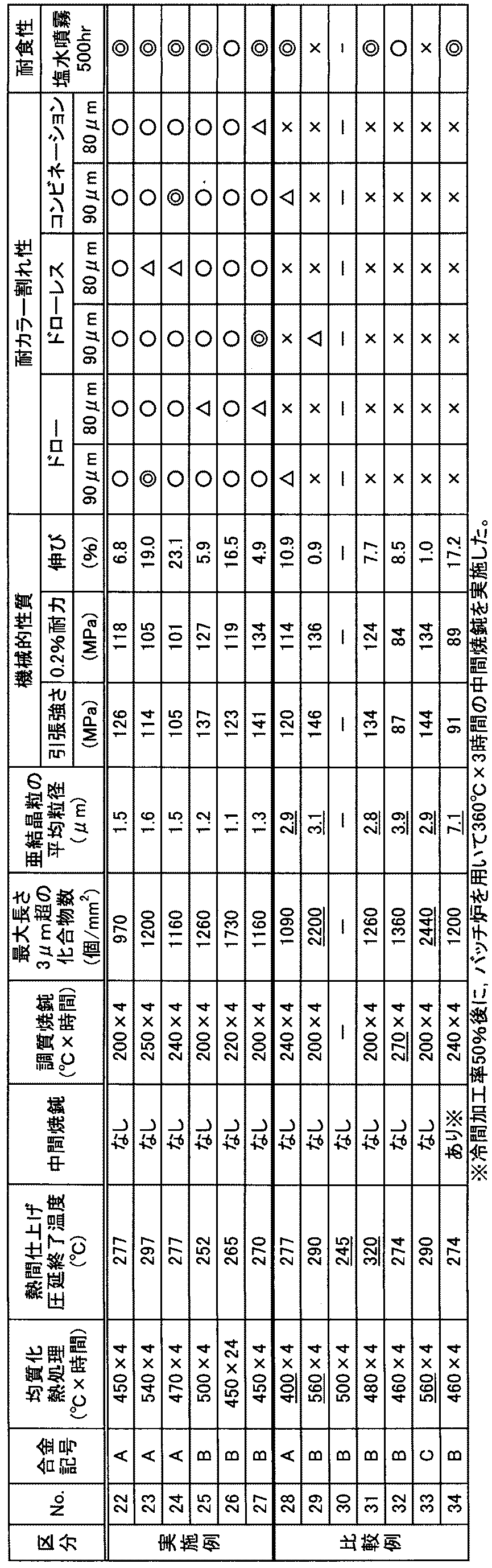
- Example No. 22 to 27, Comparative Example No. 28 to 34 Aluminum alloys shown in Table 2 (Alloys A, B, and C corresponding to Table 1) were melted and cast to form ingots, and after the surfaces were subjected to face grinding, homogenization heat treatment and hot rolling were performed. A hot rolled plate having a thickness of 3.0 mm was used. Furthermore, no. Except for 34, the steel sheet was cold-rolled at a cold working rate of about 97.0% or 97.3% to make the plate thickness 90 ⁇ m and 80 ⁇ m, and then subjected to temper annealing to obtain a fin material. No. In No.
- a hot rolled plate having a thickness of 3.0 mm was subjected to cold rolling at a cold working rate of 50%, and then subjected to intermediate annealing at 360 ° C. for 3 hours using a batch furnace. Thereafter, cold rolling was performed at a cold working rate of about 94.0% or 94.7%, respectively, so that the plate thickness was 90 ⁇ m and 80 ⁇ m, and then temper annealing was performed to obtain a fin material.
- Table 2 shows the conditions for the homogenization heat treatment, the finish temperature of the hot finish rolling, and the temper annealing. In addition, No. 30 is a thing which could not manufacture a fin material.
- Example No. 35 to 38 Comparative Example No. 39 to 42
- No. in Table 2 No. 22 which is the same fin material as that of No. 22. 35, 36, No. 2 in Table 2.
- No. 27, which is the same fin material as No. 27. 37, 38, No. 2 in Table 2.
- No. 29, which is the same fin material as No. 29. 39, 40, No. 2 in Table 2.
- No. 32 which is the same fin material as No. 32.
- the following surface treatments were performed on 41 and 42.
- No. 1 Surface treatment under the same conditions as Comparative Example 1 of JP 2010-223520 A (comprising a chemical conversion film, a hydrophilic film, and a lubricating film in this order)
- No. 2 Surface treatment under the same conditions as Example 1 of Japanese Patent No. 3383914 (comprising a chemical conversion film, a hydrophilic film, and a lubricating resin film in this order)
- No. 3 Surface treatment under the same conditions as in Example 1 of JP 2008-224204 (comprising a chemical conversion film, a corrosion-resistant resin film, and a hydrophilic film in this order)
- No. 4 Surface treatment under the same conditions as Comparative Example 21 of JP 2010-223514 A (comprising a chemical conversion film and a corrosion-resistant resin film in this order)
- the average grain size of subcrystal grains and the number of intermetallic compounds of 3 ⁇ m or more were measured by the following method. Furthermore, strength and elongation were measured by the following methods.
- the average grain size of the sub-crystal grains is obtained by analyzing the orientation of the crystal structure of a scanning electron microscope (SEM) image obtained by photographing the sample surface at an observation magnification of 1,000 times by the EBSD method at a measurement interval of 0.10 ⁇ m. Based on the calculation, it was automatically calculated on OIM (Orientation Imaging Microscopy, (registered trademark)) software manufactured by TSL. That is, the total area of the fin material was divided by the number of crystal grains counted by SEM / EBSD measurement data, and the diameter when the area of each crystal grain was approximated to a circle was defined as the average grain size of the subcrystal grains. As for the number of crystal grains, a crystal grain surrounded by a crystal grain boundary whose orientation difference between adjacent crystal grains is within 2 ° was counted as one crystal grain.
- SEM scanning electron microscope
- the number of intermetallic compounds exceeding 3 ⁇ m was calculated by image analysis of an image taken with a scanning electron microscope (SEM) obtained by photographing a sample surface with an observation magnification of 500 times and an area of 1.0 mm 2 .
- the size of a compound means the maximum length of each compound.
- the produced fin material was press-molded by draw molding, drawless molding and combination molding, and the color cracking resistance was evaluated.
- the color cracking resistance evaluation was evaluated by visually counting the cracks generated in the collar portion with respect to 400 holes of the press-formed product.
- the occurrence rate is “number of cracks / 400 ⁇ 100 (%)”, and the occurrence rate is less than 3% ()), 3% to less than 5% ( ⁇ ), 5% to less than 10% ( ⁇ ), 10 % Or more was taken as (x). Then, all of (90) and 80 ⁇ m of draw molding, 90 ⁇ m and 80 ⁇ m of draw molding, and 90 ⁇ m and 80 ⁇ m of combination molding were evaluated as acceptable.
- the prepared fin material having a thickness of 80 ⁇ m was first subjected to surface treatment under the following conditions.
- Surface treatment The fin material was immersed in an alkaline degreasing solution and degreased for 5 seconds, and then immersed in a phosphoric acid chromate solution to form a phosphate chromate film of 15 to 40 mg / m 2 on the surface of the fin material.
- the phosphoric acid chromate-treated fin material is coated with an epoxy resin corrosion-resistant resin coating with a bar coater to a coating amount of 300 mg / m 2 , and baked at 260 ° C. for 10 seconds.
- No. No. 15 was inferior in corrosion resistance due to the Cu content exceeding the upper limit, and also caused work hardening and inferior color cracking resistance.
- No. 16 since the Mn content exceeded the upper limit, coarse intermetallic compounds increased, and the color cracking resistance and corrosion resistance were inferior.
- No. No. 17 since the Mn content exceeds the upper limit and the temper annealing temperature exceeds the upper limit, the coarse intermetallic compound increases, the subcrystal grain size increases, and the color cracking resistance Inferior to corrosion resistance.
- No. No. 30 because the finish temperature of hot finish rolling was less than the lower limit, rolling itself was difficult, and the fin material could not be manufactured.
- No. 32 the temperature of the temper annealing exceeded the upper limit, so the subcrystal grain size was large and the color cracking resistance was inferior.
- No. No. 33 was inferior in color cracking resistance and corrosion resistance because the temperature of the homogenization heat treatment exceeded the upper limit, resulting in an increase in coarse intermetallic compounds, an increase in sub-crystal grains.
- No. No. 34 is an intermediate annealing, so that the cold work rate is less than the lower limit. Therefore, the average grain size of the sub-crystal grains exceeded the upper limit value, and the color cracking resistance was poor.
- the fin materials of 16, 13, 17, and 33 are assumed to be the conventional aluminum alloy fin materials described in Patent Document 1, Patent Document 2, Patent Document 3, and Patent Document 4, respectively. As shown in this example, these conventional aluminum alloy fin materials do not satisfy a certain level in the above evaluation. Therefore, this example objectively revealed that the aluminum alloy fin material for heat exchanger according to the present invention is superior to the conventional aluminum alloy fin material.
Landscapes
- Chemical & Material Sciences (AREA)
- Engineering & Computer Science (AREA)
- Mechanical Engineering (AREA)
- Materials Engineering (AREA)
- Metallurgy (AREA)
- Organic Chemistry (AREA)
- Physics & Mathematics (AREA)
- Thermal Sciences (AREA)
- Crystallography & Structural Chemistry (AREA)
- Metal Rolling (AREA)
- Chemical Treatment Of Metals (AREA)
Description
本発明は、熱交換器に用いられる熱交換器用アルミニウム合金フィン材およびその製造方法に関する。
近年、空調器等の熱交換器に用いる熱交換器用アルミニウム合金フィン材(以下、適宜、フィン材という)においても、フロン規制に沿った新冷媒への切り替えや、空調器自身のコンパクト化や軽量化あるいは高性能化等により、益々薄肉化が図られ、板厚が0.15mm以下、最近では0.09mm程度にまで薄肉化されている。
ここで、フィン材の成形法には、ドロー方式、ドローレス方式およびドロー・ドローレス複合方式(コンビネーション方式)がある。ドロー方式は、張出し工程、絞り工程、打ち抜き(ピアス)および穴広げ工程(バーリング)、リフレア工程からなり、ドローレス方式は、打ち抜きおよび穴広げ工程、しごき(アイアニング)工程、リフレア工程からなり、コンビネーション方式は、主に、張出し工程、絞り工程、打ち抜きおよび穴広げ工程、しごき工程、リフレア工程からなる。
1970年代のフィン材の開発の当初は、上記の3つの成形法のうち、ドロー方式が採用されており、張出し成形性に優れた軟質なアルミニウム合金が使用されていた。その後、薄肉化・高強度化の流れに対応するため、ドローレス方式の採用が増加し、しごき加工時の焼付き低減などのために、Mnを含有する硬質なアルミニウム合金が使用され始めた。さらにその後、環境問題から、プレス油の有機溶剤洗浄の廃止が検討され、洗浄不要な揮発性プレスの使用が増加したこと、プレコートフィン材の使用が拡大したことなどを受けて、ドロー・ドローレス複合方式(コンビネーション方式)が採用されるようになり、薄肉であっても強度と成形性に優れた各種アルミニウム合金の開発が進んでいる。
これら何れの成形法においても、銅管における管用穴カラーを成形するためのピアス&バーリング成形とリフレア成形は、フィン材にとって必要不可欠な成形工程である。ただし、これらの成形は、板厚が0.15mm以下にまで薄肉化されたフィン材にとって、過酷な成形となる。そのため、このような薄肉化に対応して、加工性を向上させたフィン材が開発されている。
例えば、特許文献1には、板厚が0.15mm以下であり、金属間化合物の粒径、大傾角粒の最大の長さ、大傾角粒内の亜結晶粒の平均粒径等を所定に規定した、成形加工性に優れたアルミニウム合金フィン材が開示されている。また、特許文献2には、板厚が0.11mm未満であり、Fe、Tiを所定量含有し、Si、Cuを所定量以下に規制するとともに、伸び率を所定に規定した、耐アベック性、スタック性に優れた熱交換器用アルミニウム合金フィン材が開示されている。特許文献3には、板厚が0.11mm未満であり、所定元素の含有量を所定に規定した、耐アベック性に優れた熱交換器用アルミニウム合金フィン材が開示されている。また、特許文献4には、冷間圧延後の板厚が0.115mmであり、所定元素を所定に規定した、ドローレスフィン用高強度アルミニウム合金薄板とその製造方法が開示されている。
しかしながら、従来のフィン材においては、以下のような問題がある。
前記した従来の技術では、加工性の向上が図られてはいるものの、近年においては、熱交換器のさらなるコンパクト化や軽量化、高性能化に加え、より加工のし易いフィン材の供給が期待されていることから、さらなる加工性の向上が求められている。
前記した従来の技術では、加工性の向上が図られてはいるものの、近年においては、熱交換器のさらなるコンパクト化や軽量化、高性能化に加え、より加工のし易いフィン材の供給が期待されていることから、さらなる加工性の向上が求められている。
また、成形中には、しばしばカラー割れと言われる割れが生じることがある。すなわち、ピアス&バーリング工程時に加工端面に微細な亀裂が生じ、これによって最終リフレア成形時にカラー割れとなる。このようなカラー割れが生じた場合、フィン成形された成形品のカラー穴に銅管を通してその銅管を拡管する際に、積層したフィンの間隔が極端に狭くなってしまうという、所謂アベック現象が生じ易くなる。そして、このアベック現象により、熱交換器の通風抵抗が増大するという問題がある。すなわち、カラー割れは、フィンの外観を損ねるだけではなく、熱交換器としての性能低下等の不具合が生じ、製品としての価値を低下させてしまうという問題がある。したがって、このようなカラー割れの発生をより抑制することができるフィン材の開発が求められている。
ここで、特許文献1に記載のフィン材は、耐カラー割れ性の改善を図っている。しかし、Mnの含有量および製造条件によっては、粗大な金属間化合物、あるいは、固溶Mnにより加工硬化しやすくなるという問題がある。そのため、耐カラー割れの改善には余地がある。
ここで、特許文献1に記載のフィン材は、耐カラー割れ性の改善を図っている。しかし、Mnの含有量および製造条件によっては、粗大な金属間化合物、あるいは、固溶Mnにより加工硬化しやすくなるという問題がある。そのため、耐カラー割れの改善には余地がある。
また、エアコン等に供される熱交換器には、室内において熱交換することを目的とする室内機と、その熱を室外の大気と交換することを目的とする室外機がある。室外機においては、フィン材は大気中に曝露されることとなるため、腐食発生防止を目的として、フィン材表面には、耐食性処理が施されている。また、エアコン等の熱交換器が設置される環境には、室外機の場合は、高湿度環境、沿岸地域等の塩害環境、酸性雨による酸性環境、室内機の場合は、高湿度環境、特殊施設等の様々な腐食促進環境が存在する。こうした環境に熱交換器を設置すると、フィン材の腐食が進行しやすく、熱交換器の故障や劣化の促進、アルミニウム基板の腐食による不快臭発生の原因になるという問題を有していた。一方、耐食性を確保するため、耐食層(耐食性処理層)の膜厚を厚くすることは、成形加工時に皮膜割れや剥離を引き起こしやすくし、熱伝導率低下の要因ともなるため、耐食層の薄膜化が進んでおり,素材自体の耐食性の向上が求められている。
本発明は、前記問題点に鑑みてなされたものであり、成形加工時におけるカラー割れの発生を抑制することができる耐カラー割れ性および耐食性に優れた熱交換器用アルミニウム合金フィン材を提供することを課題とする。
すなわち、本発明に係る熱交換器用アルミニウム合金フィン材は、Fe:0.010~0.4質量%を含有し、Cu:0.005質量%未満に抑制し、残部がAlおよび不可避的不純物からなり、Al純度が99.30質量%以上のアルミニウム合金からなる熱交換器用アルミニウム合金フィン材であって、前記熱交換器用アルミニウム合金フィン材の板厚が0.115mm未満であり、亜結晶粒の平均粒径が2.5μm以下、および、最大長さが3μmを超える金属間化合物が2000個/mm2以下であることを特徴とする。
このような構成によれば、Feを所定量添加することで、Al-Fe系金属間化合物が形成され、あるいは、アルミニウムマトリクス中に固溶して、プレス成形時における亜結晶粒が微細化されて加工硬化が抑制される。またCuを所定量未満に抑制することで、フィン材が薄肉化したときであっても耐食性の低下が抑制される。またAl純度を規定することで、金属間化合物の増加が抑制される。そして、亜結晶粒の平均粒径を2.5μm以下とすることで、0.115mm未満の板厚のフィン材での伸びが増加する。また、最大長さが3μmを超える金属間化合物を2000個/mm2以下とすることで、粗大な金属間化合物が起点となることによるカラー割れの発生が防止される。
本発明に係る熱交換器用アルミニウム合金フィン材は、前記アルミニウム合金の化学成分について、さらに、Si:0.20質量%未満、Mn:0.015質量%未満、Cr:0.015質量%以下に抑制することを特徴とする。
このような構成によれば、Si、Mn、Crを所定量以下または所定量未満に抑制することで、晶出物(すなわち金属間化合物)の粗大化が抑制される。
本発明に係る熱交換器用アルミニウム合金フィン材は、前記アルミニウム合金の化学成分について、さらに、Ti:0.01~0.05質量%を含有することを特徴とする。
このような構成によれば、Tiを所定量添加することで、鋳塊組織が微細化される。
このような構成によれば、Tiを所定量添加することで、鋳塊組織が微細化される。
本発明に係る熱交換器用アルミニウム合金フィン材は、フィン材表面に表面処理皮膜を備えたものであってもよい。表面処理皮膜としては、耐食性皮膜や親水性皮膜、潤滑性皮膜等が挙げられる。
このような構成によれば、耐食性や親水性、成形性等、使用環境や用途等に応じた特性を向上させることができる。
このような構成によれば、耐食性や親水性、成形性等、使用環境や用途等に応じた特性を向上させることができる。
本発明に係る熱交換器用アルミニウム合金フィン材の製造方法は、前記記載の熱交換器用アルミニウム合金フィン材(表面処理皮膜を備えないもの)の製造方法であって、前記アルミニウム合金の化学成分を有するアルミニウム合金鋳塊に、450~550℃の温度で1時間以上の熱処理を施す熱処理工程と、前記熱処理後に、熱間仕上げ圧延の終了温度が250℃以上300℃未満となる条件で熱間圧延を施す熱間圧延工程と、前記熱間圧延後に、冷間加工率96%以上の冷間加工を施す冷間加工工程と、前記冷間加工後に、160~260℃の温度で1~6時間保持する調質焼鈍を施す調質焼鈍工程と、を行うことを特徴とする。
このような製造方法によれば、熱処理工程により鋳塊の組織が均質化され、熱間圧延工程により、熱延板で再結晶組織となることなく圧延される。そして、冷間加工工程により、調質焼鈍後に亜結晶粒の粗大化を生じさせることなく、0.115mm未満の板厚とされ、調質焼鈍工程により充分に組織が回復するとともに亜結晶粒の微細化が促進される。
本発明に係る熱交換器用アルミニウム合金フィン材は、成形加工したときのカラー割れおよび耐食性を抑制することができる。そのため、フィンの外観を損ねることや、熱交換器としての性能低下等の不具合を防止することができる。
また、本発明に係る熱交換器用アルミニウム合金フィン材の製造方法は、耐カラー割れ性と耐食性に優れた熱交換器用アルミニウム合金フィン材を製造することができる。
以下、本発明に係る熱交換器用アルミニウム合金フィン材(以下、適宜、フィン材という)およびフィン材の製造方法を実現するための形態について説明する。
<フィン材>
本発明に係るフィン材は、Feを所定量含有し、Cuを所定量以下に抑制し、残部がAlおよび不可避的不純物からなり、Al純度が99.30質量%以上のアルミニウム合金からなるものである。そして、このフィン材の板厚が0.115mm未満であり、亜結晶粒の平均粒径を2.5μm以下、および、3μmを超える金属間化合物を2000個/mm2以下に規定したものである。また、アルミニウム合金に含まれる不可避的不純物のうち、Si、Mn、Crを所定量以下または所定量未満に抑制することが好ましい。さらに、必要に応じてTiを所定量含有してもよい。
以下、各構成について、まず、化学成分について説明した後、その他の構成について説明する。
本発明に係るフィン材は、Feを所定量含有し、Cuを所定量以下に抑制し、残部がAlおよび不可避的不純物からなり、Al純度が99.30質量%以上のアルミニウム合金からなるものである。そして、このフィン材の板厚が0.115mm未満であり、亜結晶粒の平均粒径を2.5μm以下、および、3μmを超える金属間化合物を2000個/mm2以下に規定したものである。また、アルミニウム合金に含まれる不可避的不純物のうち、Si、Mn、Crを所定量以下または所定量未満に抑制することが好ましい。さらに、必要に応じてTiを所定量含有してもよい。
以下、各構成について、まず、化学成分について説明した後、その他の構成について説明する。
(Fe:0.010~0.4質量%)
Feは、Al-Fe系金属間化合物を形成(あるいは、アルミニウムマトリクス中に固溶)して、プレス成形時における亜結晶粒を微細にすることができるために、加工硬化抑制に寄与する元素であり、カラー割れ不良を減少させる効果がある。また、アルミニウム合金板の亜結晶粒の大きさに寄与する効果や、強度を向上させる効果も有する。Fe含有量が0.010質量%未満では、前記の効果が得られずに、プレス成形でカラー割れ性に劣る。一方、0.4質量%を超えると、粗大な金属間化合物が形成され、耐カラー割れ性が劣る。したがって、Fe含有量は、0.010~0.4質量%とする。
Feは、Al-Fe系金属間化合物を形成(あるいは、アルミニウムマトリクス中に固溶)して、プレス成形時における亜結晶粒を微細にすることができるために、加工硬化抑制に寄与する元素であり、カラー割れ不良を減少させる効果がある。また、アルミニウム合金板の亜結晶粒の大きさに寄与する効果や、強度を向上させる効果も有する。Fe含有量が0.010質量%未満では、前記の効果が得られずに、プレス成形でカラー割れ性に劣る。一方、0.4質量%を超えると、粗大な金属間化合物が形成され、耐カラー割れ性が劣る。したがって、Fe含有量は、0.010~0.4質量%とする。
(Cu:0.005質量%未満(0質量%を含む))
Cu含有量が、0.005質量%以上であると、素材または/および耐食層が薄肉化した時に耐食性を低下させる。したがって、Cu含有量は、0.005質量%未満に抑制する。なお、0質量%まで抑制してもよい。
Cu含有量が、0.005質量%以上であると、素材または/および耐食層が薄肉化した時に耐食性を低下させる。したがって、Cu含有量は、0.005質量%未満に抑制する。なお、0質量%まで抑制してもよい。
(Si:0.20質量%未満(0質量%を含む))
Siは、不可避的不純物として混入する元素であるが、Si含有量が0.20質量%以上になると、晶出物(金属間化合物)が粗大化し、これが成形加工時の応力集中点となり、割れの起点となる。したがって、Siを含有する場合には、Si含有量は、0.20質量%未満、好ましくは0.17質量%以下に抑制する。なお、0質量%まで抑制してもよい。
Siは、不可避的不純物として混入する元素であるが、Si含有量が0.20質量%以上になると、晶出物(金属間化合物)が粗大化し、これが成形加工時の応力集中点となり、割れの起点となる。したがって、Siを含有する場合には、Si含有量は、0.20質量%未満、好ましくは0.17質量%以下に抑制する。なお、0質量%まで抑制してもよい。
(Mn:0.015質量%未満(0質量%を含む))
Mnは、不可避的不純物として混入する元素であるが、Mn含有量が0.015質量%以上になると、晶出物(金属間化合物)が粗大化し、これが成形加工時の応力集中点となり、割れの起点となる。したがって、Mnを含有する場合には、Mn含有量は、0.015質量%未満に抑制する。さらには、0.005質量%未満に抑制することが好ましい。なお、0質量%まで抑制してもよい。
Mnは、不可避的不純物として混入する元素であるが、Mn含有量が0.015質量%以上になると、晶出物(金属間化合物)が粗大化し、これが成形加工時の応力集中点となり、割れの起点となる。したがって、Mnを含有する場合には、Mn含有量は、0.015質量%未満に抑制する。さらには、0.005質量%未満に抑制することが好ましい。なお、0質量%まで抑制してもよい。
(Cr:0.015質量%以下(0質量%を含む))
Crは、不可避的不純物として混入する元素であるが、Cr含有量が0.015質量%を超えると、晶出物(金属間化合物)が粗大化し、これが成形加工時の応力集中点となり、割れの起点となる。したがって、Crを含有する場合には、Cr含有量は、0.015質量%以下に抑制する。なお、0質量%まで抑制してもよい。
Crは、不可避的不純物として混入する元素であるが、Cr含有量が0.015質量%を超えると、晶出物(金属間化合物)が粗大化し、これが成形加工時の応力集中点となり、割れの起点となる。したがって、Crを含有する場合には、Cr含有量は、0.015質量%以下に抑制する。なお、0質量%まで抑制してもよい。
(Ti:0.01~0.05質量%)
Tiは、鋳塊組織の微細化のために、Al-Ti-B中間合金として添加しても良い。すなわち、Ti:B=5:1あるいは5:0.2の割合としたAl-Ti-B鋳塊微細化剤を、ワッフルあるいはロッドの形態で溶湯(スラブ凝固前における、溶解炉、介在物フィルター、脱ガス装置、溶湯流量制御装置へ投入された、いずれかの段階での溶湯)へ添加してもよく、Ti量で、0.05質量%までの含有は許容される。Ti含有量が0.01質量%未満では、鋳塊組織微細化の効果が得られない。一方、0.05質量%を超えると、晶出物(金属間化合物)が粗大化し、これが成形加工時の応力集中点となり、割れの起点となる。したがって、Tiを添加する場合には、Ti含有量は、0.01~0.05質量%とする。
Tiは、鋳塊組織の微細化のために、Al-Ti-B中間合金として添加しても良い。すなわち、Ti:B=5:1あるいは5:0.2の割合としたAl-Ti-B鋳塊微細化剤を、ワッフルあるいはロッドの形態で溶湯(スラブ凝固前における、溶解炉、介在物フィルター、脱ガス装置、溶湯流量制御装置へ投入された、いずれかの段階での溶湯)へ添加してもよく、Ti量で、0.05質量%までの含有は許容される。Ti含有量が0.01質量%未満では、鋳塊組織微細化の効果が得られない。一方、0.05質量%を超えると、晶出物(金属間化合物)が粗大化し、これが成形加工時の応力集中点となり、割れの起点となる。したがって、Tiを添加する場合には、Ti含有量は、0.01~0.05質量%とする。
(残部:Alおよび不可避的不純物)
フィン材の成分は前記の他、残部がAlおよび不可避的不純物からなるものである。なお、不可避的不純物として、前記したSi、Mn、Crの他、例えば、地金や中間合金に含まれている、通常知られている範囲内のMg、Zn、Zr、Ce、Ga、V、Ni等は、Al純度が、99.30質量%未満とならない範囲で、それぞれ0.05質量%までの含有は許容される。
フィン材の成分は前記の他、残部がAlおよび不可避的不純物からなるものである。なお、不可避的不純物として、前記したSi、Mn、Crの他、例えば、地金や中間合金に含まれている、通常知られている範囲内のMg、Zn、Zr、Ce、Ga、V、Ni等は、Al純度が、99.30質量%未満とならない範囲で、それぞれ0.05質量%までの含有は許容される。
(Al純度:99.30質量%以上)
Al純度が、99.30質量%未満では、金属間化合物の増加に伴い、カラー割れが増加し、耐食性が低下する。したがって、Al純度は、99.30質量%以上とする。
Al純度が、99.30質量%未満では、金属間化合物の増加に伴い、カラー割れが増加し、耐食性が低下する。したがって、Al純度は、99.30質量%以上とする。
(板厚:0.115mm未満)
本発明は、近年における熱交換器のコンパクト化や軽量化、高性能化等の要請により、フィン材の薄肉化を図る観点から、0.115mm未満の板厚のフィン材を対象とする。したがって、フィン材の板厚は、0.115mm未満とする。本発明では、亜結晶粒の平均粒径を2.5μm以下に制約しており、薄肉となっても破壊の起点となる懸念は少ないため、本発明の特徴が一層発揮できるという観点から、0.100mm未満であることが好ましく、0.090mm以下であるとより好ましい。
本発明は、近年における熱交換器のコンパクト化や軽量化、高性能化等の要請により、フィン材の薄肉化を図る観点から、0.115mm未満の板厚のフィン材を対象とする。したがって、フィン材の板厚は、0.115mm未満とする。本発明では、亜結晶粒の平均粒径を2.5μm以下に制約しており、薄肉となっても破壊の起点となる懸念は少ないため、本発明の特徴が一層発揮できるという観点から、0.100mm未満であることが好ましく、0.090mm以下であるとより好ましい。
(亜結晶粒の平均粒径:2.5μm以下)
0.115mm未満の板厚のフィン材での耐カラー割れ性向上のためには、合金中の亜結晶粒の平均粒径を2.5μm以下とすることが必要である。亜結晶粒の平均粒径が2.5μmを超えると、亜結晶粒内に応力が集中し、割れの起点が増加し、耐カラー割れ性が劣る。したがって、亜結晶粒の平均粒径は、2.5μm以下とする。なお、下限値は特に規定しないが、0μmであってもよい(すなわち、亜結晶粒を含まなくてもよい)。この様な範囲にすることにより、固溶Mnや固溶Cu等により加工硬化するような場合であっても、カラー割れの発生を抑制することができる。
0.115mm未満の板厚のフィン材での耐カラー割れ性向上のためには、合金中の亜結晶粒の平均粒径を2.5μm以下とすることが必要である。亜結晶粒の平均粒径が2.5μmを超えると、亜結晶粒内に応力が集中し、割れの起点が増加し、耐カラー割れ性が劣る。したがって、亜結晶粒の平均粒径は、2.5μm以下とする。なお、下限値は特に規定しないが、0μmであってもよい(すなわち、亜結晶粒を含まなくてもよい)。この様な範囲にすることにより、固溶Mnや固溶Cu等により加工硬化するような場合であっても、カラー割れの発生を抑制することができる。
(最大長さが3μmを超える金属間化合物:2000個/mm2以下)
粗大な金属間化合物は、カラー割れの起点となり、また、亀裂が伝播する過程でマイクロクラック(微小な亀裂)の発生により亀裂伝播を助長する。したがって、サイズが3μmを超える金属間化合物は2000個/mm2以下とする。なお、化合物のサイズとは化合物の輪郭線上任意の2点間距離の最大値を言う。また、サイズの上限については、定めはなく、個数については、0であってもよい。
粗大な金属間化合物は、カラー割れの起点となり、また、亀裂が伝播する過程でマイクロクラック(微小な亀裂)の発生により亀裂伝播を助長する。したがって、サイズが3μmを超える金属間化合物は2000個/mm2以下とする。なお、化合物のサイズとは化合物の輪郭線上任意の2点間距離の最大値を言う。また、サイズの上限については、定めはなく、個数については、0であってもよい。
次に、亜結晶粒の平均粒径および金属間化合物の個数の測定方法について説明する。
まず、走査型電子顕微鏡(SEM:Scanning Electron Microscopy)による画像の結晶組織をEBSD(Electron Back Scattered Diffraction Pattern)法により方位解析する。EBSD法は、試料に電子線を照射し、その際に生じる反射電子菊池線回折を利用して結晶方位を特定するものである。また、結晶方位解析には、例えば、TSL社製OIM(Orientation Imaging Microscopy、(登録商標))を用いることができる。
そして、亜結晶粒の平均粒径は、このSEM/EBSD測定データにより結晶粒の数を算出し、フィン材の全面積を結晶粒の数で除し、各結晶粒の面積を円と近似した場合の直径を亜結晶粒の平均粒径と定義する。金属間化合物の個数は、観察倍率500倍で、面積1.0mm2の試料表面を撮影した走査型電子顕微鏡(SEM)による画像を画像解析することにより算出する。
まず、走査型電子顕微鏡(SEM:Scanning Electron Microscopy)による画像の結晶組織をEBSD(Electron Back Scattered Diffraction Pattern)法により方位解析する。EBSD法は、試料に電子線を照射し、その際に生じる反射電子菊池線回折を利用して結晶方位を特定するものである。また、結晶方位解析には、例えば、TSL社製OIM(Orientation Imaging Microscopy、(登録商標))を用いることができる。
そして、亜結晶粒の平均粒径は、このSEM/EBSD測定データにより結晶粒の数を算出し、フィン材の全面積を結晶粒の数で除し、各結晶粒の面積を円と近似した場合の直径を亜結晶粒の平均粒径と定義する。金属間化合物の個数は、観察倍率500倍で、面積1.0mm2の試料表面を撮影した走査型電子顕微鏡(SEM)による画像を画像解析することにより算出する。
なお、亜結晶粒の平均粒径および金属間化合物の個数は、成分組成と、後記する製造条件により制御することができる。具体的には、亜結晶粒の平均粒径は、各成分の含有量、均質化熱処理条件(温度と時間)、熱間仕上げ圧延終了温度、冷間加工率、調質焼鈍条件(温度と時間)、金属間化合物の個数は、各成分の含有量、均質化熱処理条件(温度と時間)等により制御する。
本発明に係るフィン材は、フィン材表面に表面処理皮膜を備えたものであってもよい。なお、フィン材表面とは、フィン材の片面もしくは両面を意味する。
(表面処理皮膜)
表面処理皮膜としては、使用環境や用途に応じ、化成皮膜や樹脂皮膜、無機皮膜が挙げられ、これらを組み合わせ(化成皮膜上に樹脂皮膜、無機皮膜を設け)てもよい。また、樹脂皮膜、無機皮膜としては、耐食性樹脂皮膜、親水性樹脂皮膜、親水性無機皮膜、潤滑性樹脂皮膜等が挙げられ、これらを適宜組み合わせてもよい。
(表面処理皮膜)
表面処理皮膜としては、使用環境や用途に応じ、化成皮膜や樹脂皮膜、無機皮膜が挙げられ、これらを組み合わせ(化成皮膜上に樹脂皮膜、無機皮膜を設け)てもよい。また、樹脂皮膜、無機皮膜としては、耐食性樹脂皮膜、親水性樹脂皮膜、親水性無機皮膜、潤滑性樹脂皮膜等が挙げられ、これらを適宜組み合わせてもよい。
化成皮膜としては、例えばリン酸クロメートが挙げられる。耐食性樹脂皮膜としては、エポキシ系、ウレタン系、アクリル系、ポリエステル系等の樹脂が挙げられ、その膜厚は、0.5~5μmが好ましい。親水性皮膜としては、水ガラス系の無機物、ポリアクリル酸またはポリアクリル酸塩を含有するような樹脂、スルホン酸基またはスルホン酸基誘導体を含有するような樹脂等が挙げられ、その膜厚は、0.05~10μmが好ましい。潤滑性樹脂皮膜としてはポリエーテルポリオールを含有する樹脂などが挙げられ、その膜厚は、0.1~10μmが好ましい。
耐食性樹脂皮膜、親水性樹脂皮膜、親水性無機皮膜、潤滑性樹脂皮膜のうち2種以上を組み合わせる場合には、耐食性樹脂皮膜の表面側に親水性樹脂皮膜が設けられ、親水性樹脂皮膜、親水性無機皮膜の表面側に潤滑性樹脂皮膜が設けられることが好ましい。
<フィン材の製造方法>
本発明に係るフィン材の製造方法は、前記したフィン材の製造方法であって、熱処理工程と、熱間圧延工程と、冷間加工工程と、調質焼鈍工程と、を行うものである。さらに必要に応じて、鋳塊作製工程や表面処理工程を含んでもよい。
以下、各工程について説明する。
本発明に係るフィン材の製造方法は、前記したフィン材の製造方法であって、熱処理工程と、熱間圧延工程と、冷間加工工程と、調質焼鈍工程と、を行うものである。さらに必要に応じて、鋳塊作製工程や表面処理工程を含んでもよい。
以下、各工程について説明する。
(鋳塊作製工程)
鋳塊作製工程は、アルミニウム合金を溶解、鋳造してアルミニウム合金鋳塊を作製する工程である。
鋳塊作製工程では、前記した化学成分を有するアルミニウム合金を溶解した溶湯から、所定形状の鋳塊を作製する。アルミニウム合金を溶解、鋳造する方法は、特に限定されるものではなく、従来公知の方法を用いればよい。例えば、真空誘導炉を用いて溶解し、連続鋳造法や、半連続鋳造法を用いて鋳造することができる。
鋳塊作製工程は、アルミニウム合金を溶解、鋳造してアルミニウム合金鋳塊を作製する工程である。
鋳塊作製工程では、前記した化学成分を有するアルミニウム合金を溶解した溶湯から、所定形状の鋳塊を作製する。アルミニウム合金を溶解、鋳造する方法は、特に限定されるものではなく、従来公知の方法を用いればよい。例えば、真空誘導炉を用いて溶解し、連続鋳造法や、半連続鋳造法を用いて鋳造することができる。
(熱処理工程)
熱処理工程は、前記アルミニウム合金の化学成分を有するアルミニウム合金鋳塊に、450~550℃の温度で1時間以上の熱処理(均質化熱処理)を施す工程である。
熱処理温度が450℃未満では、鋳塊の組織の均質化が不十分となる。また、熱間加工性の低下を招く。さらに亜結晶粒径が大きくなる。一方、550℃を超えると、加熱中で微細化する微細金属間化合物が粗大化し、亜結晶粒が粗大化して伸びが低下する。また、固溶量の増加を招く。したがって、熱処理温度は、450~550℃、好ましくは500℃超え530℃以下とする。また、熱処理は保持時間1時間以上であれば前記効果を得られるため、特に上限を規定する必要はない。一方で、10時間を超えると効果が飽和することから、経済的には、熱処理時間は24時間以内が好ましい。
熱処理工程は、前記アルミニウム合金の化学成分を有するアルミニウム合金鋳塊に、450~550℃の温度で1時間以上の熱処理(均質化熱処理)を施す工程である。
熱処理温度が450℃未満では、鋳塊の組織の均質化が不十分となる。また、熱間加工性の低下を招く。さらに亜結晶粒径が大きくなる。一方、550℃を超えると、加熱中で微細化する微細金属間化合物が粗大化し、亜結晶粒が粗大化して伸びが低下する。また、固溶量の増加を招く。したがって、熱処理温度は、450~550℃、好ましくは500℃超え530℃以下とする。また、熱処理は保持時間1時間以上であれば前記効果を得られるため、特に上限を規定する必要はない。一方で、10時間を超えると効果が飽和することから、経済的には、熱処理時間は24時間以内が好ましい。
(熱間圧延工程)
熱間圧延工程は、前記熱処理後に、熱間仕上げ圧延の終了温度が250℃以上300℃未満となる条件で熱間圧延を施す工程である。
熱間仕上げ圧延の終了温度が250℃未満では、材料の圧延性が低下し、圧延自体が困難となったり、板厚制御が難しくなったりして、生産性が低下する。一方、300℃以上では、熱延板で再結晶組織となるために、調質焼鈍後に繊維状の同一結晶方位群が生成し、ピアス&バーリング工程時にくびれを生じる。また、亜結晶粒径が大きくなる。したがって、熱間仕上げ圧延の終了温度は、250℃以上300℃未満とする。より好ましくは、260~290℃である。
熱間圧延工程は、前記熱処理後に、熱間仕上げ圧延の終了温度が250℃以上300℃未満となる条件で熱間圧延を施す工程である。
熱間仕上げ圧延の終了温度が250℃未満では、材料の圧延性が低下し、圧延自体が困難となったり、板厚制御が難しくなったりして、生産性が低下する。一方、300℃以上では、熱延板で再結晶組織となるために、調質焼鈍後に繊維状の同一結晶方位群が生成し、ピアス&バーリング工程時にくびれを生じる。また、亜結晶粒径が大きくなる。したがって、熱間仕上げ圧延の終了温度は、250℃以上300℃未満とする。より好ましくは、260~290℃である。
(冷間加工工程)
冷間加工工程は、前記熱間圧延後に、冷間加工率96%以上の冷間加工(冷間圧延)を施す工程である。
熱間圧延終了後、冷間加工を1回、あるいは複数回行なって、フィン材を所望の最終板厚とする。ただし、冷間加工率が96%未満では、調質焼鈍後に亜結晶粒が粗大化する。したがって、冷間加工における冷間加工率は、96%以上とする。ここで、冷間加工の途中で中間焼鈍を行なった場合、冷間加工率は中間焼鈍後から最終板厚までの加工率である。よって、中間焼鈍を行なうと、96%以上の冷間加工率とすることが困難となることから、中間焼鈍は行なわない。なお、冷間加工率は高いほど好ましいため、上限は特に設けない。
冷間加工工程は、前記熱間圧延後に、冷間加工率96%以上の冷間加工(冷間圧延)を施す工程である。
熱間圧延終了後、冷間加工を1回、あるいは複数回行なって、フィン材を所望の最終板厚とする。ただし、冷間加工率が96%未満では、調質焼鈍後に亜結晶粒が粗大化する。したがって、冷間加工における冷間加工率は、96%以上とする。ここで、冷間加工の途中で中間焼鈍を行なった場合、冷間加工率は中間焼鈍後から最終板厚までの加工率である。よって、中間焼鈍を行なうと、96%以上の冷間加工率とすることが困難となることから、中間焼鈍は行なわない。なお、冷間加工率は高いほど好ましいため、上限は特に設けない。
(調質焼鈍工程)
調質焼鈍工程は、前記冷間加工後に、160~260℃の温度で1~6時間保持する調質焼鈍(仕上げ焼鈍)を施す工程である。
調質焼鈍の温度が160℃未満では、充分な組織の回復効果が得られない。一方、260℃を超えると、焼鈍後に再結晶粒を生じ、これを起点に割れが生じる。また、亜結晶粒の微細化が促進されない。したがって、調質焼鈍の温度は、160~260℃とする。
調質焼鈍工程は、前記冷間加工後に、160~260℃の温度で1~6時間保持する調質焼鈍(仕上げ焼鈍)を施す工程である。
調質焼鈍の温度が160℃未満では、充分な組織の回復効果が得られない。一方、260℃を超えると、焼鈍後に再結晶粒を生じ、これを起点に割れが生じる。また、亜結晶粒の微細化が促進されない。したがって、調質焼鈍の温度は、160~260℃とする。
ここで、フィン材をドローレス成形に用いる場合には、調質焼鈍の温度の上限は、230℃とすることが好ましい。ドローレス成形の場合には、調質焼鈍の温度が230℃を超えると、コンビネーション成形の場合に比べ、成形性がやや低下する傾向にあるが、230℃以下であれば、230℃を超えた場合よりも成形性がより向上するためである。したがって、ドローレス成形用の場合には、160~230℃とすることが好ましい。
なお、調質焼鈍は1時間以上行うことが通常であり、6時間を超えると効果が飽和することから、保持時間は1~6時間とする。
なお、調質焼鈍は1時間以上行うことが通常であり、6時間を超えると効果が飽和することから、保持時間は1~6時間とする。
(表面処理工程)
表面処理工程は、調質焼鈍後のフィン材に表面処理を施す工程である。
表面処理工程において、化成皮膜を形成する場合には、通常の塗布型または反応型の薬剤を用いた化成処理によって行うことができる。耐食性樹脂皮膜、親水性樹脂皮膜、潤滑性樹脂皮膜等の樹脂皮膜を形成する場合には、ロールコーターを用いた塗布、乾燥によって行うことができる。
表面処理工程は、調質焼鈍後のフィン材に表面処理を施す工程である。
表面処理工程において、化成皮膜を形成する場合には、通常の塗布型または反応型の薬剤を用いた化成処理によって行うことができる。耐食性樹脂皮膜、親水性樹脂皮膜、潤滑性樹脂皮膜等の樹脂皮膜を形成する場合には、ロールコーターを用いた塗布、乾燥によって行うことができる。
なお、本発明を行うにあたり、前記各工程に悪影響を与えない範囲において、前記各工程の間あるいは前後に、他の工程を含めてもよい。例えば、ごみ等の異物を除去する異物除去工程や、鋳塊に面削を施す面削工程や、調質焼鈍工程や表面処理工程の後に、フィン材として必要な、機械加工を適宜施す機械加工工程等を含めてもよい。
そして、このようにして製造されたフィン材は、各成形法に応じて成形加工されるが、本発明のフィン材は、特にドローレス成形またはコンビネーション成形に好適である。
ドローレス成形は、第1工程で打ち抜きおよび穴広げ加工(ピアス&バーリング成形)、第2、第3工程でしごき加工、第4工程でリフレア加工を施すものである。また、コンビネーション成形は、第1工程で張出し、第2工程で絞り成形、第3工程で打ち抜きおよび穴広げ加工(ピアス&バーリング成形)、第4工程でしごき加工、第5工程でリフレア加工を施すものである。そして、本発明のフィン材は、耐カラー割れ性に優れるため、これら成形加工時のカラー割れの発生を抑制することができる。
ドローレス成形は、第1工程で打ち抜きおよび穴広げ加工(ピアス&バーリング成形)、第2、第3工程でしごき加工、第4工程でリフレア加工を施すものである。また、コンビネーション成形は、第1工程で張出し、第2工程で絞り成形、第3工程で打ち抜きおよび穴広げ加工(ピアス&バーリング成形)、第4工程でしごき加工、第5工程でリフレア加工を施すものである。そして、本発明のフィン材は、耐カラー割れ性に優れるため、これら成形加工時のカラー割れの発生を抑制することができる。
以上、本発明を実施するための形態について述べてきたが、以下に、本発明の効果を確認した実施例を、本発明の要件を満たさない比較例と対比して具体的に説明する。なお、本発明はこの実施例に限定されるものではない。
〔供試材作製〕
(実施例No.1~10、比較例No.11~21)
表1に示す組成のアルミニウム合金を、溶解、鋳造して鋳塊とし、この鋳塊に面削を施した後に、480℃にて4時間の均質化熱処理を施した。この均質化した鋳塊に、熱間仕上げ圧延の終了温度を270℃となるように制御して熱間圧延を施し、板厚3.0mmの熱間圧延板とした。さらに、それぞれ97.0%または97.3%程度の冷間加工率で冷間圧延を施して板厚を90μmおよび80μmとした後、表1に示す温度および保持時間の調質焼鈍を施してフィン材とした。
(実施例No.1~10、比較例No.11~21)
表1に示す組成のアルミニウム合金を、溶解、鋳造して鋳塊とし、この鋳塊に面削を施した後に、480℃にて4時間の均質化熱処理を施した。この均質化した鋳塊に、熱間仕上げ圧延の終了温度を270℃となるように制御して熱間圧延を施し、板厚3.0mmの熱間圧延板とした。さらに、それぞれ97.0%または97.3%程度の冷間加工率で冷間圧延を施して板厚を90μmおよび80μmとした後、表1に示す温度および保持時間の調質焼鈍を施してフィン材とした。
(実施例No.22~27、比較例No.28~34)
表2に示すアルミニウム合金(表1に対応する合金A,B,C)を、溶解、鋳造して鋳塊とし、この鋳塊に面削を施した後に、均質化熱処理、熱間圧延を施し、板厚3.0mmの熱間圧延板とした。さらに、No.34以外は、それぞれ97.0%または97.3%程度の冷間加工率で冷間圧延を施して板厚を90μmおよび80μmとした後、調質焼鈍を施してフィン材とした。No.34は、板厚3.0mmの熱間圧延板に50%の冷間加工率で冷間圧延を施した後、バッチ炉を用いて360℃×3hの中間焼鈍を実施した。その後さらに、それぞれ94.0%または94.7%程度の冷間加工率で冷間圧延を施して板厚を90μmおよび80μmとした後、調質焼鈍を施してフィン材とした。均質化熱処理、熱間仕上げ圧延の終了温度、調質焼鈍の条件は、表2に示すとおりである。なお、No.30はフィン材を製造できなかったものである。
表2に示すアルミニウム合金(表1に対応する合金A,B,C)を、溶解、鋳造して鋳塊とし、この鋳塊に面削を施した後に、均質化熱処理、熱間圧延を施し、板厚3.0mmの熱間圧延板とした。さらに、No.34以外は、それぞれ97.0%または97.3%程度の冷間加工率で冷間圧延を施して板厚を90μmおよび80μmとした後、調質焼鈍を施してフィン材とした。No.34は、板厚3.0mmの熱間圧延板に50%の冷間加工率で冷間圧延を施した後、バッチ炉を用いて360℃×3hの中間焼鈍を実施した。その後さらに、それぞれ94.0%または94.7%程度の冷間加工率で冷間圧延を施して板厚を90μmおよび80μmとした後、調質焼鈍を施してフィン材とした。均質化熱処理、熱間仕上げ圧延の終了温度、調質焼鈍の条件は、表2に示すとおりである。なお、No.30はフィン材を製造できなかったものである。
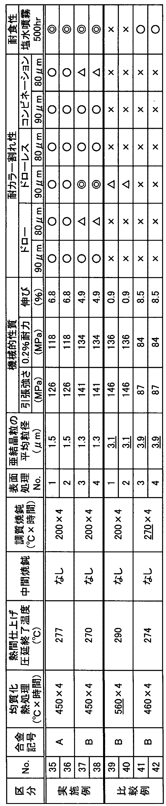
(実施例No.35~38、比較例No.39~42)
表2のNo.22と同様のフィン材であるNo.35、36、表2のNo.27と同様のフィン材であるNo.37、38、表2のNo.29と同様のフィン材であるNo.39、40、表2のNo.32と同様のフィン材であるNo.41、42に対して以下の表面処理(No.1~4)を行った。
表2のNo.22と同様のフィン材であるNo.35、36、表2のNo.27と同様のフィン材であるNo.37、38、表2のNo.29と同様のフィン材であるNo.39、40、表2のNo.32と同様のフィン材であるNo.41、42に対して以下の表面処理(No.1~4)を行った。
No.1:特開2010-223520号公報の比較例1と同じ条件の表面処理(化成皮膜、親水性皮膜、潤滑性皮膜をこの順に備える)
No.2:特許第3383914号公報の実施例1と同じ条件の表面処理(化成皮膜、親水性皮膜、潤滑性樹脂皮膜をこの順に備える)
No.3:特開2008-224204号公報の実施例1と同じ条件の表面処理(化成皮膜、耐食性樹脂皮膜、親水性皮膜をこの順に備える)
No.4:特開2010-223514号公報の比較例21と同じ条件の表面処理(化成皮膜、耐食性樹脂皮膜をこの順に備える)
No.2:特許第3383914号公報の実施例1と同じ条件の表面処理(化成皮膜、親水性皮膜、潤滑性樹脂皮膜をこの順に備える)
No.3:特開2008-224204号公報の実施例1と同じ条件の表面処理(化成皮膜、耐食性樹脂皮膜、親水性皮膜をこの順に備える)
No.4:特開2010-223514号公報の比較例21と同じ条件の表面処理(化成皮膜、耐食性樹脂皮膜をこの順に備える)
成分組成を表1に、製造条件を表2、3に示す。なお、表中、本発明の範囲を満たさないものは、数値に下線を引いて示し、成分を含有しないものは、「-」で示す。なお、No.30はフィン材を製造できなかったものであるため、調質焼鈍の欄に「-」と記す。また、No.16は、特許文献1の記載に基づくアルミニウム合金フィン材に基づくものであり(表2の発明例1(但し、熱延終了温度および熱間圧延後の板厚(3.5mm)が異なる)、No.13は、特許文献2の記載に基づくアルミニウム合金フィン材に基づくものである(表1の発明例4(但し、加工方式(ドロー加工)が異なる))。また、No.17は、特許文献3の記載に基づくアルミニウム合金フィン材に基づくものであり(表1の発明例3)、No.33は、特許文献4の記載に基づくアルミニウム合金フィン材に基づくものである(表2の発明例11(但し、冷間圧延後の板厚(0.115mm厚)が異なる))。
次に、フィン材の組織形態として、亜結晶粒の平均粒径および3μm以上の金属間化合物の個数を以下の方法により測定した。さらに、強度および伸びを以下の方法により測定した。
〔亜結晶粒の平均粒径〕
亜結晶粒の平均粒径は、観察倍率1,000倍で試料表面を撮影した走査型電子顕微鏡(SEM)による画像の結晶組織を、測定間隔0.10μmにてEBSD法により方位解析したデータを基に、TSL社製OIM(Orientation Imaging Microscopy、(登録商標))ソフト上で自動計算することにより算出した。すなわち、フィン材の全面積をSEM/EBSD測定データによりカウントされた結晶粒の数で除し、各結晶粒の面積を円と近似した場合の直径を亜結晶粒の平均粒径と定義した。なお、結晶粒の数は、隣接結晶粒間の方位差が2°以内の結晶粒界に囲まれた結晶粒を一つの結晶粒としてカウントした。
亜結晶粒の平均粒径は、観察倍率1,000倍で試料表面を撮影した走査型電子顕微鏡(SEM)による画像の結晶組織を、測定間隔0.10μmにてEBSD法により方位解析したデータを基に、TSL社製OIM(Orientation Imaging Microscopy、(登録商標))ソフト上で自動計算することにより算出した。すなわち、フィン材の全面積をSEM/EBSD測定データによりカウントされた結晶粒の数で除し、各結晶粒の面積を円と近似した場合の直径を亜結晶粒の平均粒径と定義した。なお、結晶粒の数は、隣接結晶粒間の方位差が2°以内の結晶粒界に囲まれた結晶粒を一つの結晶粒としてカウントした。
〔3μmを超える金属間化合物の個数〕
サイズが3μmを超える化合物数は、観察倍率500倍で、面積1.0mm2の試料表面を撮影した走査型電子顕微鏡(SEM)による画像を画像解析することにより算出した。なお、化合物のサイズとは個々の化合物の最大の長さを言う。
サイズが3μmを超える化合物数は、観察倍率500倍で、面積1.0mm2の試料表面を撮影した走査型電子顕微鏡(SEM)による画像を画像解析することにより算出した。なお、化合物のサイズとは個々の化合物の最大の長さを言う。
〔引張強さ、0.2%耐力、伸び〕
フィン材から、引張方向が圧延方向と平行になるようにJIS5号による引張試験片を切り出した。この試験片で、JISZ2241による引張試験を実施し、引張強さ、0.2%耐力、および、伸びを測定した。なお、本実施例および比較例の評価における引張速度は5mm/minで行った。
フィン材から、引張方向が圧延方向と平行になるようにJIS5号による引張試験片を切り出した。この試験片で、JISZ2241による引張試験を実施し、引張強さ、0.2%耐力、および、伸びを測定した。なお、本実施例および比較例の評価における引張速度は5mm/minで行った。
〔耐カラー割れ性評価〕
作製したフィン材にドロー成形、ドローレス成形およびコンビネーション成形によりプレス成形を実施し、耐カラー割れ性を評価した。耐カラー割れ性評価は、プレス成形品400穴に対して、カラー部に生じた割れを目視にてカウントすることで評価した。
「割れ数/400×100(%)」を発生率とし、発生率が3%未満を(◎)、3%以上5%未満を(○)、5%以上10%未満を(△)、10%以上を(×)とした。そして、ドロー成形の90μmおよび80μm、ドローレス成形の90μmおよび80μm、コンビネーション成形の90μmおよび80μmのすべてにおいて(◎)、(○)、(△)のいずれかであったものを合格とした。
作製したフィン材にドロー成形、ドローレス成形およびコンビネーション成形によりプレス成形を実施し、耐カラー割れ性を評価した。耐カラー割れ性評価は、プレス成形品400穴に対して、カラー部に生じた割れを目視にてカウントすることで評価した。
「割れ数/400×100(%)」を発生率とし、発生率が3%未満を(◎)、3%以上5%未満を(○)、5%以上10%未満を(△)、10%以上を(×)とした。そして、ドロー成形の90μmおよび80μm、ドローレス成形の90μmおよび80μm、コンビネーション成形の90μmおよび80μmのすべてにおいて(◎)、(○)、(△)のいずれかであったものを合格とした。
〔表面処理材の耐食性評価〕
作製した板厚80μmのフィン材に対して、まず下記の条件で表面処理を行った。
表面処理:フィン材をアルカリ性脱脂液へ浸漬して脱脂を5秒間行い、次にリン酸クロメート液に浸漬してリン酸クロメートの皮膜15~40mg/m2をフィン材表面に形成した。このリン酸クロメート処理されたフィン材に、エポキシ樹脂の耐食性樹脂塗料を300mg/m2の皮膜量になるようにバーコーターで塗装し、260℃で10秒間焼付けを行い、最後に、水溶性セルロース系樹脂塗料を皮膜量200mg/m2になるように上塗りして、230℃で10秒間焼付けを行った。
表面処理されたフィン材に対して、塩水を500時間噴霧した。
その後、供試材の腐食状況を目視によって観察し、腐食面積率に応じて、JIS Z2371に規定されたレイティングナンバ法によって点数を付した。RtNo9.5以上(◎)、RtNo9.3以上9.5未満(○)、RtNo9以上9.3未満(○△)として、以上の3つを合格とし、RtNo9未満を不合格(×)として表1~3に示した。
作製した板厚80μmのフィン材に対して、まず下記の条件で表面処理を行った。
表面処理:フィン材をアルカリ性脱脂液へ浸漬して脱脂を5秒間行い、次にリン酸クロメート液に浸漬してリン酸クロメートの皮膜15~40mg/m2をフィン材表面に形成した。このリン酸クロメート処理されたフィン材に、エポキシ樹脂の耐食性樹脂塗料を300mg/m2の皮膜量になるようにバーコーターで塗装し、260℃で10秒間焼付けを行い、最後に、水溶性セルロース系樹脂塗料を皮膜量200mg/m2になるように上塗りして、230℃で10秒間焼付けを行った。
表面処理されたフィン材に対して、塩水を500時間噴霧した。
その後、供試材の腐食状況を目視によって観察し、腐食面積率に応じて、JIS Z2371に規定されたレイティングナンバ法によって点数を付した。RtNo9.5以上(◎)、RtNo9.3以上9.5未満(○)、RtNo9以上9.3未満(○△)として、以上の3つを合格とし、RtNo9未満を不合格(×)として表1~3に示した。
測定結果および評価結果を表1~3に示す。なお、表中、本発明の範囲を満たさないものは、数値に下線を引いて示し、フィン材の製造ができないために、測定および評価ができなかったものは、「-」で示す。

(成分による評価)
表1に示すように、実施例であるNo.1~10は、本発明の範囲を満たすものであり、ドロー法、ドローレス法およびコンビネーション法のいずれの成形法を用いた場合であっても、耐カラー割れ性に優れており、耐食性にも優れたものであった。
表1に示すように、実施例であるNo.1~10は、本発明の範囲を満たすものであり、ドロー法、ドローレス法およびコンビネーション法のいずれの成形法を用いた場合であっても、耐カラー割れ性に優れており、耐食性にも優れたものであった。
一方、比較例であるNo.11~21は、本発明の範囲を満たさないため、以下の結果となった。
No.11は、Si含有量が上限値を超えるため、粗大な金属間化合物が増加し、耐カラー割れ性および耐食性に劣った。
No.11は、Si含有量が上限値を超えるため、粗大な金属間化合物が増加し、耐カラー割れ性および耐食性に劣った。
No.12は、Fe含有量が下限値未満のため、亜結晶粒径が大きくなり、耐カラー割れ性に劣った。No.13は、Fe含有量が上限値を超えるため、また、Al純度が下限値未満のため、粗大な金属間化合物が増加し、耐カラー割れ性および耐食性に劣った。No.14は、Al純度が下限値未満のため、粗大な金属間化合物が増加し、耐カラー割れ性および耐食性に劣った。
No.15は、Cu含有量が上限値を超えるため、耐食性に劣り、また加工硬化を招き、耐カラー割れ性に劣った。No.16は、Mn含有量が上限値を超えるため、粗大な金属間化合物が増加し、耐カラー割れ性および耐食性に劣った。No.17は、Mn含有量が上限値を超えるため、また、調質焼鈍の温度が上限値を超えるため、粗大な金属間化合物が増加し、また、亜結晶粒径が大きくなり、耐カラー割れ性および耐食性に劣った。
No.18は、Cr含有量が上限値を超えるため、粗大な金属間化合物が増加し、耐カラー割れ性および耐食性に劣った。No.19は、Ti含有量が上限値を超えるため、粗大な金属間化合物が増加し、耐カラー割れ性および耐食性に劣った。No.20は、Ti含有量が上限値を超えるため、粗大な金属間化合物が増加し、耐カラー割れ性および耐食性に劣った。No.21は、Fe含有量が上限値を超えるため、粗大な金属間化合物が増加し、耐カラー割れ性および耐食性に劣った。
(製造方法による評価)
表2に示すように、実施例であるNo.22~27は、本発明の範囲を満たすものであり、いずれの成形法を用いた場合であっても、耐カラー割れ性に優れており、耐食性にも優れたものであった。
表2に示すように、実施例であるNo.22~27は、本発明の範囲を満たすものであり、いずれの成形法を用いた場合であっても、耐カラー割れ性に優れており、耐食性にも優れたものであった。
一方、比較例であるNo.28~34は、本発明の範囲を満たさないため、以下の結果となった。
No.28は、均質化熱処理の温度が下限値未満のため、亜結晶粒が大きくなり、耐カラー割れ性に劣った。No.29は、均質化熱処理の温度が上限値を超えるため、粗大な金属間化合物が増加し、また、亜結晶粒が大きくなり、耐カラー割れ性および耐食性に劣った。
No.28は、均質化熱処理の温度が下限値未満のため、亜結晶粒が大きくなり、耐カラー割れ性に劣った。No.29は、均質化熱処理の温度が上限値を超えるため、粗大な金属間化合物が増加し、また、亜結晶粒が大きくなり、耐カラー割れ性および耐食性に劣った。
No.30は、熱間仕上げ圧延の終了温度が下限値未満のため、圧延自体が困難であり、フィン材の製造ができなかった。No.31は、熱間仕上げ圧延の終了温度が上限値を超えるため、亜結晶粒が大きくなり、耐カラー割れ性に劣った。No.32は、調質焼鈍の温度が上限値を超えるため、亜結晶粒径が大きくなり、耐カラー割れ性に劣った。No.33は、均質化熱処理の温度が上限値を超えるため、粗大な金属間化合物が増加し、また、亜結晶粒が大きくなり、耐カラー割れ性および耐食性に劣った。No.34は、中間焼鈍を行なったため、冷間加工率が下限値未満となったものである。そのため、亜結晶粒の平均粒径が上限値を超え、耐カラー割れ性に劣った。
(表面処理を施した場合の評価)
No.35~42における表面処理を施したフィン材の耐カラー割れ性および耐食性は、表面処理を実施していないフィン材と同様の結果となった。
No.35~42における表面処理を施したフィン材の耐カラー割れ性および耐食性は、表面処理を実施していないフィン材と同様の結果となった。
なお、No.16、13、17、33のフィン材は、それぞれ特許文献1、特許文献2、特許文献3、特許文献4に記載された従来のアルミニウム合金フィン材を想定したものである。本実施例で示すように、これら従来のアルミニウム合金フィン材は、前記の評価において一定の水準を満たさないものである。従って、本実施例によって、本発明に係る熱交換器用アルミニウム合金フィン材が従来のアルミニウム合金フィン材と比較して、優れていることが客観的に明らかとなった。
以上、本発明に係るフィン材およびその製造方法について実施の形態および実施例を示して詳細に説明したが、本発明の趣旨は前記した内容に限定されるものではない。なお、本発明の内容は、前記した記載に基づいて広く改変・変更等することができることはいうまでもない。
Claims (5)
- Fe:0.010~0.4質量%を含有し、Cu:0.005質量%未満に抑制し、残部がAlおよび不可避的不純物からなり、Al純度が99.30質量%以上のアルミニウム合金からなる熱交換器用アルミニウム合金フィン材であって、
前記熱交換器用アルミニウム合金フィン材の板厚が0.115mm未満であり、亜結晶粒の平均粒径が2.5μm以下、および、最大長さが3μmを超える金属間化合物が2000個/mm2以下であることを特徴とする熱交換器用アルミニウム合金フィン材。 - 前記アルミニウム合金の化学成分について、さらに、Si:0.20質量%未満、Mn:0.015質量%未満、Cr:0.015質量%以下に抑制することを特徴とする請求項1に記載の熱交換器用アルミニウム合金フィン材。
- 前記アルミニウム合金の化学成分について、さらに、Ti:0.01~0.05質量%を含有することを特徴とする請求項1または請求項2に記載の熱交換器用アルミニウム合金フィン材。
- フィン材表面に表面処理皮膜を備えることを特徴とする請求項1または請求項2に記載の熱交換器用アルミニウム合金フィン材。
- 請求項1または請求項2に記載の熱交換器用アルミニウム合金フィン材の製造方法であって、
前記アルミニウム合金の化学成分を有するアルミニウム合金鋳塊に、450~550℃の温度で1時間以上の熱処理を施す熱処理工程と、
前記熱処理後に、熱間仕上げ圧延の終了温度が250℃以上300℃未満となる条件で熱間圧延を施す熱間圧延工程と、
前記熱間圧延後に、冷間加工率96%以上の冷間加工を施す冷間加工工程と、
前記冷間加工後に、160~260℃の温度で1~6時間保持する調質焼鈍を施す調質焼鈍工程と、を行うことを特徴とする熱交換器用アルミニウム合金フィン材の製造方法。
Priority Applications (1)
| Application Number | Priority Date | Filing Date | Title |
|---|---|---|---|
| CN201380051294.4A CN104685081B (zh) | 2012-10-03 | 2013-09-25 | 热交换器用铝合金翅片材及其制造方法 |
Applications Claiming Priority (2)
| Application Number | Priority Date | Filing Date | Title |
|---|---|---|---|
| JP2012221658A JP5828825B2 (ja) | 2012-10-03 | 2012-10-03 | 熱交換器用アルミニウム合金フィン材と熱交換器の製造方法 |
| JP2012-221658 | 2012-10-03 |
Publications (1)
| Publication Number | Publication Date |
|---|---|
| WO2014054486A1 true WO2014054486A1 (ja) | 2014-04-10 |
Family
ID=50434814
Family Applications (1)
| Application Number | Title | Priority Date | Filing Date |
|---|---|---|---|
| PCT/JP2013/075895 Ceased WO2014054486A1 (ja) | 2012-10-03 | 2013-09-25 | 熱交換器用アルミニウム合金フィン材およびその製造方法 |
Country Status (3)
| Country | Link |
|---|---|
| JP (1) | JP5828825B2 (ja) |
| CN (1) | CN104685081B (ja) |
| WO (1) | WO2014054486A1 (ja) |
Cited By (1)
| Publication number | Priority date | Publication date | Assignee | Title |
|---|---|---|---|---|
| CN114341378A (zh) * | 2019-09-03 | 2022-04-12 | 日本轻金属株式会社 | 光亮性铝合金和光亮性铝合金模铸材料 |
Families Citing this family (1)
| Publication number | Priority date | Publication date | Assignee | Title |
|---|---|---|---|---|
| JP2014224323A (ja) * | 2014-07-01 | 2014-12-04 | 株式会社神戸製鋼所 | 熱交換器用アルミニウム合金フィン材と熱交換機 |
Citations (7)
| Publication number | Priority date | Publication date | Assignee | Title |
|---|---|---|---|---|
| JPH08313191A (ja) * | 1995-03-16 | 1996-11-29 | Furukawa Electric Co Ltd:The | 熱交換器用アルミニウムフィン材 |
| JP2006104488A (ja) * | 2004-09-08 | 2006-04-20 | Kobe Steel Ltd | 成形加工性に優れたアルミニウム合金フィン材 |
| JP2009250510A (ja) * | 2008-04-04 | 2009-10-29 | Mitsubishi Electric Corp | 熱交換器およびその製造方法 |
| WO2012029594A1 (ja) * | 2010-09-03 | 2012-03-08 | 株式会社神戸製鋼所 | 熱交換器用アルミニウム合金フィン材およびその製造方法 |
| JP2012214844A (ja) * | 2011-03-31 | 2012-11-08 | Kobe Steel Ltd | 熱交換器用アルミニウム合金フィン材およびその製造方法 |
| JP2012214842A (ja) * | 2011-03-31 | 2012-11-08 | Kobe Steel Ltd | ドローレスプレス用熱交換器用アルミニウム合金フィン材およびその製造方法 |
| JP2012214843A (ja) * | 2011-03-31 | 2012-11-08 | Kobe Steel Ltd | コンビネーションプレス用熱交換器用アルミニウム合金フィン材およびその製造方法 |
Family Cites Families (2)
| Publication number | Priority date | Publication date | Assignee | Title |
|---|---|---|---|---|
| JP4563204B2 (ja) * | 2004-02-13 | 2010-10-13 | 株式会社デンソー | 熱交換器用アルミニウム合金押出材およびその製造方法 |
| JP5613548B2 (ja) * | 2010-12-14 | 2014-10-22 | 三菱アルミニウム株式会社 | 熱交換器用アルミニウム合金フィン材および該フィン材を用いた熱交換器 |
-
2012
- 2012-10-03 JP JP2012221658A patent/JP5828825B2/ja not_active Expired - Fee Related
-
2013
- 2013-09-25 WO PCT/JP2013/075895 patent/WO2014054486A1/ja not_active Ceased
- 2013-09-25 CN CN201380051294.4A patent/CN104685081B/zh not_active Expired - Fee Related
Patent Citations (7)
| Publication number | Priority date | Publication date | Assignee | Title |
|---|---|---|---|---|
| JPH08313191A (ja) * | 1995-03-16 | 1996-11-29 | Furukawa Electric Co Ltd:The | 熱交換器用アルミニウムフィン材 |
| JP2006104488A (ja) * | 2004-09-08 | 2006-04-20 | Kobe Steel Ltd | 成形加工性に優れたアルミニウム合金フィン材 |
| JP2009250510A (ja) * | 2008-04-04 | 2009-10-29 | Mitsubishi Electric Corp | 熱交換器およびその製造方法 |
| WO2012029594A1 (ja) * | 2010-09-03 | 2012-03-08 | 株式会社神戸製鋼所 | 熱交換器用アルミニウム合金フィン材およびその製造方法 |
| JP2012214844A (ja) * | 2011-03-31 | 2012-11-08 | Kobe Steel Ltd | 熱交換器用アルミニウム合金フィン材およびその製造方法 |
| JP2012214842A (ja) * | 2011-03-31 | 2012-11-08 | Kobe Steel Ltd | ドローレスプレス用熱交換器用アルミニウム合金フィン材およびその製造方法 |
| JP2012214843A (ja) * | 2011-03-31 | 2012-11-08 | Kobe Steel Ltd | コンビネーションプレス用熱交換器用アルミニウム合金フィン材およびその製造方法 |
Cited By (1)
| Publication number | Priority date | Publication date | Assignee | Title |
|---|---|---|---|---|
| CN114341378A (zh) * | 2019-09-03 | 2022-04-12 | 日本轻金属株式会社 | 光亮性铝合金和光亮性铝合金模铸材料 |
Also Published As
| Publication number | Publication date |
|---|---|
| CN104685081B (zh) | 2017-04-05 |
| JP5828825B2 (ja) | 2015-12-09 |
| CN104685081A (zh) | 2015-06-03 |
| JP2014074198A (ja) | 2014-04-24 |
Similar Documents
| Publication | Publication Date | Title |
|---|---|---|
| JP5060632B2 (ja) | 熱交換器用アルミニウム合金フィン材およびその製造方法 | |
| WO2015002315A1 (ja) | 熱交換器用ブレージングシート及びその製造方法 | |
| JP5830451B2 (ja) | コンビネーションプレス用熱交換器用アルミニウム合金フィン材 | |
| JP5828657B2 (ja) | 熱交換器用アルミニウム合金フィン材 | |
| JP5693333B2 (ja) | コンビネーションプレス用熱交換器用アルミニウム合金フィン材 | |
| JP5828825B2 (ja) | 熱交換器用アルミニウム合金フィン材と熱交換器の製造方法 | |
| JP5843462B2 (ja) | ドローレスプレス用熱交換器用アルミニウム合金フィン材 | |
| JP2014224323A (ja) | 熱交換器用アルミニウム合金フィン材と熱交換機 | |
| WO2012132784A1 (ja) | ドローレスプレス用熱交換器用アルミニウム合金フィン材およびその製造方法 | |
| WO2012132785A1 (ja) | コンビネーションプレス用熱交換器用アルミニウム合金フィン材およびその製造方法 | |
| JP4996909B2 (ja) | アルミニウム合金ブレージングシートおよびその製造方法 | |
| JPH06212371A (ja) | 成形用高強度アルミニウム合金フィン材の製造方法 | |
| JP5807079B2 (ja) | 熱交換器用アルミニウム合金フィン材 | |
| JP5764240B2 (ja) | コンビネーションプレス用熱交換器用アルミニウム合金フィン材 | |
| JP5923841B2 (ja) | ドローレスプレス用熱交換器用アルミニウム合金フィン材 | |
| JP2009046705A (ja) | 耐食性に優れた熱交換器用押出扁平多穴管及び熱交換器 | |
| JP2014231641A (ja) | コンビネーションプレス用熱交換器用アルミニウム合金フィン材 | |
| JP6328374B2 (ja) | 熱交換器用アルミニウム合金フィン材およびその製造方法 | |
| JP2021021127A (ja) | 銅合金材料及び熱交換器 |
Legal Events
| Date | Code | Title | Description |
|---|---|---|---|
| 121 | Ep: the epo has been informed by wipo that ep was designated in this application |
Ref document number: 13843782 Country of ref document: EP Kind code of ref document: A1 |
|
| NENP | Non-entry into the national phase |
Ref country code: DE |
|
| 122 | Ep: pct application non-entry in european phase |
Ref document number: 13843782 Country of ref document: EP Kind code of ref document: A1 |