WO2014054317A1 - ユーザインタフェース装置及びユーザインタフェース方法 - Google Patents
ユーザインタフェース装置及びユーザインタフェース方法 Download PDFInfo
- Publication number
- WO2014054317A1 WO2014054317A1 PCT/JP2013/066941 JP2013066941W WO2014054317A1 WO 2014054317 A1 WO2014054317 A1 WO 2014054317A1 JP 2013066941 W JP2013066941 W JP 2013066941W WO 2014054317 A1 WO2014054317 A1 WO 2014054317A1
- Authority
- WO
- WIPO (PCT)
- Prior art keywords
- change
- pointing
- pointing position
- unit
- user
- Prior art date
Links
- 238000000034 method Methods 0.000 title claims description 60
- 230000008859 change Effects 0.000 claims abstract description 194
- 238000001514 detection method Methods 0.000 claims abstract description 61
- 238000011084 recovery Methods 0.000 claims description 25
- 230000004044 response Effects 0.000 claims description 24
- 230000008569 process Effects 0.000 description 31
- 238000012545 processing Methods 0.000 description 30
- 238000010586 diagram Methods 0.000 description 11
- 125000002066 L-histidyl group Chemical group [H]N1C([H])=NC(C([H])([H])[C@](C(=O)[*])([H])N([H])[H])=C1[H] 0.000 description 9
- 230000033001 locomotion Effects 0.000 description 7
- 230000004048 modification Effects 0.000 description 6
- 238000012986 modification Methods 0.000 description 6
- 238000006073 displacement reaction Methods 0.000 description 5
- 239000000203 mixture Substances 0.000 description 5
- 230000005484 gravity Effects 0.000 description 4
- 230000005540 biological transmission Effects 0.000 description 3
- 238000006243 chemical reaction Methods 0.000 description 3
- 238000004891 communication Methods 0.000 description 3
- 239000002131 composite material Substances 0.000 description 3
- 230000000694 effects Effects 0.000 description 3
- 238000005516 engineering process Methods 0.000 description 3
- 238000003384 imaging method Methods 0.000 description 3
- 230000009471 action Effects 0.000 description 2
- 230000003190 augmentative effect Effects 0.000 description 2
- 239000000284 extract Substances 0.000 description 2
- 230000015572 biosynthetic process Effects 0.000 description 1
- 239000011248 coating agent Substances 0.000 description 1
- 238000000576 coating method Methods 0.000 description 1
- 238000000605 extraction Methods 0.000 description 1
- 230000006870 function Effects 0.000 description 1
- 239000003550 marker Substances 0.000 description 1
- 238000005259 measurement Methods 0.000 description 1
- 230000035945 sensitivity Effects 0.000 description 1
- 238000003786 synthesis reaction Methods 0.000 description 1
- 230000002194 synthesizing effect Effects 0.000 description 1
- 230000000007 visual effect Effects 0.000 description 1
Images


Classifications
-
- G—PHYSICS
- G06—COMPUTING; CALCULATING OR COUNTING
- G06F—ELECTRIC DIGITAL DATA PROCESSING
- G06F3/00—Input arrangements for transferring data to be processed into a form capable of being handled by the computer; Output arrangements for transferring data from processing unit to output unit, e.g. interface arrangements
- G06F3/01—Input arrangements or combined input and output arrangements for interaction between user and computer
- G06F3/017—Gesture based interaction, e.g. based on a set of recognized hand gestures
-
- G—PHYSICS
- G06—COMPUTING; CALCULATING OR COUNTING
- G06F—ELECTRIC DIGITAL DATA PROCESSING
- G06F3/00—Input arrangements for transferring data to be processed into a form capable of being handled by the computer; Output arrangements for transferring data from processing unit to output unit, e.g. interface arrangements
- G06F3/01—Input arrangements or combined input and output arrangements for interaction between user and computer
- G06F3/011—Arrangements for interaction with the human body, e.g. for user immersion in virtual reality
-
- G—PHYSICS
- G06—COMPUTING; CALCULATING OR COUNTING
- G06F—ELECTRIC DIGITAL DATA PROCESSING
- G06F3/00—Input arrangements for transferring data to be processed into a form capable of being handled by the computer; Output arrangements for transferring data from processing unit to output unit, e.g. interface arrangements
- G06F3/01—Input arrangements or combined input and output arrangements for interaction between user and computer
- G06F3/03—Arrangements for converting the position or the displacement of a member into a coded form
- G06F3/0304—Detection arrangements using opto-electronic means
-
- G—PHYSICS
- G06—COMPUTING; CALCULATING OR COUNTING
- G06F—ELECTRIC DIGITAL DATA PROCESSING
- G06F3/00—Input arrangements for transferring data to be processed into a form capable of being handled by the computer; Output arrangements for transferring data from processing unit to output unit, e.g. interface arrangements
- G06F3/01—Input arrangements or combined input and output arrangements for interaction between user and computer
- G06F3/03—Arrangements for converting the position or the displacement of a member into a coded form
- G06F3/033—Pointing devices displaced or positioned by the user, e.g. mice, trackballs, pens or joysticks; Accessories therefor
- G06F3/038—Control and interface arrangements therefor, e.g. drivers or device-embedded control circuitry
-
- G—PHYSICS
- G06—COMPUTING; CALCULATING OR COUNTING
- G06F—ELECTRIC DIGITAL DATA PROCESSING
- G06F3/00—Input arrangements for transferring data to be processed into a form capable of being handled by the computer; Output arrangements for transferring data from processing unit to output unit, e.g. interface arrangements
- G06F3/01—Input arrangements or combined input and output arrangements for interaction between user and computer
- G06F3/048—Interaction techniques based on graphical user interfaces [GUI]
- G06F3/0481—Interaction techniques based on graphical user interfaces [GUI] based on specific properties of the displayed interaction object or a metaphor-based environment, e.g. interaction with desktop elements like windows or icons, or assisted by a cursor's changing behaviour or appearance
- G06F3/04815—Interaction with a metaphor-based environment or interaction object displayed as three-dimensional, e.g. changing the user viewpoint with respect to the environment or object
-
- G—PHYSICS
- G06—COMPUTING; CALCULATING OR COUNTING
- G06V—IMAGE OR VIDEO RECOGNITION OR UNDERSTANDING
- G06V40/00—Recognition of biometric, human-related or animal-related patterns in image or video data
- G06V40/20—Movements or behaviour, e.g. gesture recognition
- G06V40/28—Recognition of hand or arm movements, e.g. recognition of deaf sign language
-
- G—PHYSICS
- G02—OPTICS
- G02B—OPTICAL ELEMENTS, SYSTEMS OR APPARATUS
- G02B27/00—Optical systems or apparatus not provided for by any of the groups G02B1/00 - G02B26/00, G02B30/00
- G02B27/01—Head-up displays
- G02B27/017—Head mounted
- G02B2027/0178—Eyeglass type
Definitions
- the present invention relates to user interface technology.
- Various devices such as a mouse, a joystick, a trackball, and a touch panel are provided as user interface (man-machine interface) devices that allow user input to a computer.
- user interface devices that enable user input in accordance with body movements by detecting body movements (gestures) such as data gloves and data suits have been developed. With such a user interface device, the user can operate the computer with an intuitive feeling.
- Patent Document 1 proposes a technology that facilitates operation input by a user's gesture.
- the sensitivity of detecting the movement of the pointing point in the depth direction is determined based on the resolution of the distance sensor, the three-dimensional display performance of the display, and the measurement distance in the depth direction of the pointing point such as the finger of the user's hand.
- the parameters to be determined are adjusted.
- the operation input by the user's gesture is recognized by calculating the distance in the depth direction of the indication point based on the adjusted parameter.
- the above-described proposed method only assumes user input corresponding to the movement of a specific part (instruction point) of the body such as a finger of a hand, and the action of grabbing an object with the hand or the finger.
- the present invention has been made in view of such circumstances, and provides a user interface technique for operating a computer intuitively and easily by a gesture including a change in the shape of a specific part of a user.
- a user interface device includes a position acquisition unit that sequentially acquires a pointing position indicating at least one representative position of a user's specific part used for a pointing operation, and a change of the user's specific part to a predetermined shape
- a position detecting unit that detects the start and end of change, a position holding unit that holds a pointing position corresponding to the start of change detected by the change detecting unit among the pointing positions sequentially acquired by the position acquiring unit, and a position acquiring unit
- Calculating unit that specifies a pointing position corresponding to the end of the change detected by the change detecting unit among the pointing positions acquired by calculating the difference between the specified pointing position and the pointing position held by the position holding unit
- the position acquisition unit using the difference calculated by the calculation unit. It has a position adjusting unit for adjusting the in-coating position.
- the second aspect relates to a user interface method.
- at least one computer sequentially acquires a pointing position indicating at least one representative position of the user's specific part used for the pointing operation, and converts it into a predetermined shape of the user's specific part.
- the start and end of the change are detected, and the pointing position corresponding to the detected change start is sequentially held among the sequentially acquired pointing positions, and the corresponding change end is detected among the sequentially acquired pointing positions.
- the pointing position is specified, the difference between the specified pointing position and the held pointing position is calculated, and the sequentially acquired pointing position is adjusted using the calculated difference.
- a program that causes at least one computer to realize each configuration in the first aspect described above may be used, or a computer-readable recording medium that records such a program may be used.
- This recording medium includes a non-transitory tangible medium.
- FIG. 2 is a diagram conceptually illustrating a hardware configuration example of a three-dimensional user interface device (3D-UI device) in the first embodiment. It is a figure which shows the example of the utilization form of the three-dimensional user interface apparatus (3D-UI apparatus) in 1st Embodiment. It is a figure which shows the example of the external appearance structure of HMD. It is a figure which shows notionally the process structural example of the sensor side apparatus in 1st Embodiment.
- the user interface device includes a position acquisition unit that sequentially acquires a pointing position indicating at least one representative position of a user's specific part used for a pointing operation, and a change of the user's specific part to a predetermined shape
- a position detecting unit that detects the start and end of change, a position holding unit that holds a pointing position corresponding to the start of change detected by the change detecting unit among the pointing positions sequentially acquired by the position acquiring unit, and a position acquiring unit Calculating unit that specifies a pointing position corresponding to the end of the change detected by the change detecting unit among the pointing positions acquired by calculating the difference between the specified pointing position and the pointing position held by the position holding unit And the difference calculated by the calculation unit It has a position adjusting unit for adjusting the pointing position that, a.
- At least one computer sequentially obtains a pointing position indicating at least one representative position of the user's specific part used for the pointing operation, and changes to a predetermined shape of the user's specific part.
- the start and end of the change are detected, and the pointing position corresponding to the detected change start is sequentially held among the sequentially acquired pointing positions, and the corresponding change end is detected among the sequentially acquired pointing positions.
- Specifying a pointing position calculating a difference between the specified pointing position and a held pointing position, and adjusting the sequentially acquired pointing position using the calculated difference.
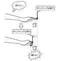
- FIG. 1 is a diagram conceptually illustrating acquisition of a pointing position.
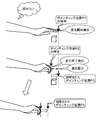
- FIG. 2 is a diagram conceptually showing a problem related to the acquisition of the pointing position.
- FIG. 3 is a diagram conceptually illustrating the adjustment of the pointing position in the above-described embodiment.
- the pointing position corresponding to the specific part of the user is sequentially acquired.
- at least one representative position of the specific part of the user is specified as the pointing position from the two-dimensional image or the three-dimensional information (for example, the two-dimensional image and the depth information) representing the specific part of the user.
- the pointing position may be obtained from skeleton information obtained by skeleton tracking of a game controller system called Kinect (registered trademark).
- the pointing position may be set to the position of the center of gravity obtained from the recognized outline of the specific part of the user.
- the present embodiment does not limit the pointing position specifying method.
- a hand is used as a specific part of the user, and a representative one point position in the hand that is farthest from the body is set as the pointing position.
- the pointing positions P1 and P2 are sequentially acquired by moving the entire arm including the user's hand.
- FIG. 2 when a cube is an object to be gripped, the pointing position with respect to the cube is appropriate, and a predetermined operation (gripping) is recognized, the computer sets the cube in a state of being gripped by the user.
- the pointing position P ⁇ b> 1 acquired when the user opens his hand is set at the fingertip of that hand.
- a position farthest from the body in the grasped hand is acquired as the pointing position P2.
- the pointing position corresponding to the specific part is shifted before and after the change in the shape. This does not depend on the method of determining the pointing position in the specific part of the user. For example, even when the center of gravity of the hand as a specific part is set as the pointing position, the position of the center of gravity when the hand is opened is different from the position of the center of gravity when the hand is gripped. It will shift.
- Such a deviation of the pointing position before and after the specific gesture causes a distance between the position of the display object to be operated with the specific gesture and the pointing position after the specific gesture, and the specific gesture is There is a possibility that it is erroneously recognized as a user input different from the intended user input. In other words, there is a possibility that the display object cannot be operated by the specific gesture.
- the user-intended operation is not performed by the change of the pointing position according to the shape change. There is a case.
- the start of change and the end of change of the specific part to the predetermined shape are detected.
- the change in the shape of the specific part of the user is detected from information obtained from a sensor such as a strain sensor mounted on a data glove or a data suit, for example. Further, the change may be detected from a two-dimensional image or three-dimensional information (for example, a two-dimensional image and depth information) representing a specific part of the user.
- the present embodiment does not limit the detection method of the change in the shape of the specific part.
- the predetermined shape is, for example, the shape of the hand in a state where an object is held when the specific part is a hand.
- the change start is detected, for example, when the shape has changed in a predetermined shape direction beyond a predetermined change width held in advance.
- the end of change is detected, for example, when a specific part of the user has a predetermined shape.
- the end of change may be detected when the shape further changes beyond the predetermined change information (such as strain information) obtained from the sensor in a state where the shape of the specific part is the predetermined shape.
- the end of the change may be detected when the shape change stops for a predetermined time held in advance.
- the pointing position P1 corresponding to the start of the change detected by the change detecting unit among the sequentially acquired pointing positions is held and further detected by the change detecting unit.
- the pointing position P2 corresponding to the end of the change is specified.
- the pointing position corresponding to the start of the change means a pointing position acquired before or after the start of the change is detected by the change detection unit. The same applies to the pointing position corresponding to the end of the change.
- the pointing position P2 corresponding to the end of the change and the held pointing position P1 is calculated, and the pointing position is adjusted using the calculated difference.
- the pointing position P4 related to the specific part in the shape at the end of the change detected by the change detecting unit is calculated as described above by the position acquisition unit related to the specific part having the shape.
- the value is adjusted by the difference.
- the addition of the difference is used as the adjustment of the pointing position.
- the adjustment of the pointing position is not limited to the addition of the difference, and the adjustment may be performed by adding a difference multiplied by a predetermined coefficient.
- the pointing position after the end of the change is determined using the deviation of the pointing position corresponding to the specific part before and after the change in the shape of the specific part of the user used for the pointing operation. Is adjusted. Therefore, according to the present embodiment, it is possible to prevent misrecognition of user input due to a displacement of the pointing position before and after the specific gesture, and as a result, it is possible to intuitively use the computer by the gesture including the change in the shape of the specific part of the user. It is possible to realize a user interface that is easy to understand.
- FIG. 4 is a diagram conceptually illustrating a hardware configuration example of the three-dimensional user interface device (hereinafter referred to as a 3D-UI device) 1 in the first embodiment.
- the 3D-UI device 1 in the first embodiment is large and has a sensor side configuration and a display side configuration.
- the sensor side configuration is formed by a three-dimensional sensor (hereinafter referred to as a 3D sensor) 8 and a sensor side device 10.
- the display side configuration is formed of a head mounted display (hereinafter referred to as HMD) 9 and a display side device 30.
- HMD head mounted display
- 3D is abbreviated as 3D as appropriate.
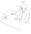
- FIG. 5 is a diagram illustrating an example of a usage mode of the 3D-UI device 1 in the first embodiment.
- the 3D sensor 8 is disposed at a position where a specific part of the user can be detected.
- the HMD 9 is mounted on the user's head and allows the user to visually recognize the above-described virtual 3D space synthesized with the line-of-sight video together with the line-of-sight video corresponding to the user's line of sight.
- the 3D sensor 8 detects 3D information used for detecting a specific part of the user.
- the 3D sensor 8 is realized by a visible light camera and a distance image sensor like Kinect (registered trademark), for example.
- a distance image sensor also called a depth sensor, irradiates a user with a pattern of near-infrared light from a laser and captures the pattern with a camera that detects the near-infrared light from the distance image sensor to the user.
- the distance (depth) of is calculated.
- the method of realizing the 3D sensor 8 itself is not limited, and the 3D sensor 8 may be realized by a three-dimensional scanner method using a plurality of visible light cameras. In FIG. 4, the 3D sensor 8 is illustrated as one element, but the 3D sensor 8 is realized by a plurality of devices such as a visible light camera that captures a two-dimensional image of the user and a sensor that detects a distance to the user. May be.
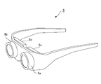
- FIG. 6 is a diagram showing an example of the external configuration of the HMD 9.
- FIG. 6 shows the configuration of an HMD 9 called a video see-through type.
- the HMD 9 has two line-of-sight cameras 9a and 9b and two displays 9c and 9d.
- Each line-of-sight camera 9a and 9b captures each line-of-sight image corresponding to each line of sight of the user.
- the HMD 9 can also be called an imaging unit.
- Each display 9c and 9d is arranged so as to cover most of the visual field of the user, and displays a combined 3D image in which a virtual 3D space is combined with each line-of-sight image.
- the sensor-side device 10 and the display-side device each have a CPU (Central Processing Unit) 2, a memory 3, a communication device 4, an input / output interface (I / F) 5, and the like that are connected to each other via a bus or the like.
- the memory 3 is a RAM (Random Access Memory), a ROM (Read Only Memory), a hard disk, a portable storage medium, or the like.
- the input / output I / F 5 of the sensor side device 10 is connected to the 3D sensor 8, and the input / output I / F 5 of the display side device 30 is connected to the HMD 9. Further, the input / output I / F 5 of the sensor-side device 10 may be connected to a sensor that acquires information on the shape change of a specific part of the user, such as a distortion sensor.
- the input / output I / F 5 and the 3D sensor 8 and the input / output I / F 5 and the HMD 9 may be connected so as to be communicable by radio.
- Each communication device 4 communicates with other devices (such as the sensor-side device 10 and the display-side device 30) in a wireless or wired manner. The present embodiment does not limit the form of such communication. Further, the specific hardware configurations of the sensor side device 10 and the display side device 30 are not limited.
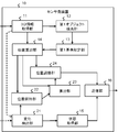
- FIG. 7 is a diagram conceptually illustrating a processing configuration example of the sensor-side device 10 in the first embodiment.
- the sensor-side device 10 in the first embodiment includes a 3D information acquisition unit 11, a first object detection unit 12, a first reference setting unit 13, a position calculation unit 14, a state acquisition unit 15, a transmission unit 16, a change detection unit 21, A position holding unit 22, a calculation unit 23, a position adjustment unit 24, and the like are included.
- Each of these processing units is realized, for example, by executing a program stored in the memory 3 by the CPU 2.
- the program may be installed from a portable recording medium such as a CD (Compact Disc) or a memory card or another computer on the network via the input / output I / F 5 and stored in the memory 3. Good.
- CD Compact Disc
- the 3D information acquisition unit 11 sequentially acquires 3D information detected by the 3D sensor 8.
- the 3D information includes a two-dimensional image of the user obtained by visible light and information on the distance (depth) from the 3D sensor 8.
- the first object detection unit 12 detects a known common real object from the 3D information acquired by the 3D information acquisition unit 11.
- the common real object is an image or an object arranged in the real world, and is called an AR (Augmented Reality) marker or the like.
- AR Augmented Reality
- the first object detection unit 12 holds in advance information on the shape, size, color, and the like indicated by the common real object, and detects the common real object from the 3D information using such known information.
- the first reference setting unit 13 sets a 3D coordinate space based on the common real object detected by the first object detection unit 12, and calculates the position and orientation of the 3D sensor 8 in the 3D coordinate space. For example, the first reference setting unit 13 sets a 3D coordinate space having the reference point extracted from the common real object as the origin and three axes orthogonal to each other from the reference point.
- the first reference setting unit 13 includes a known shape and size related to the common real object (corresponding to the original shape and size) and a shape and size indicated by the common real object extracted from the 3D information (how to see from the 3D sensor 8 And the position and orientation of the 3D sensor 8 are calculated.
- the position calculation unit 14 uses the 3D information sequentially acquired by the 3D information acquisition unit 11 to sequentially calculate the 3D pointing position on the 3D coordinate space related to the specific part of the user. Thereby, the position calculation part 14 can also be called a position acquisition part.
- the position calculation unit 14 calculates the 3D pointing position specifically as follows.
- the position calculation unit 14 first extracts a 3D pointing position indicating at least one representative position of the user's specific part from the 3D information acquired by the 3D information acquisition unit 11.
- the extraction of the 3D pointing position is performed by skeleton tracking as described above, for example.
- the 3D pointing position extracted here corresponds to the camera coordinate system of the 3D sensor 8.
- the position calculation unit 14 determines the 3D pointing position corresponding to the camera coordinate system of the 3D sensor 8 based on the position and orientation of the 3D sensor 8 and the 3D coordinate space calculated by the first reference setting unit 13 as the first reference.
- the 3D pointing position in the 3D coordinate space set by the setting unit 13 is converted. This conversion means conversion from the camera coordinate system of the 3D sensor 8 to the 3D coordinate system set based on the common real object.
- the position calculation unit 14 extracts the 3D pointing positions of a plurality of specific parts from the 3D information acquired by the 3D information acquisition unit 11, and each 3D pointing position in the 3D coordinate space is extracted from each 3D pointing position.
- the specific part is a part of the body used by the user to operate the virtual object displayed on the displays 9c and 9d of the HMD 9, and therefore has a certain area or volume. Therefore, the 3D pointing position calculated by the position calculation unit 14 may be a position of a certain point in the specific part, or may be a position of a plurality of points.
- the change detection unit 21 detects the start and end of change of a specific part of the user to a predetermined shape. Furthermore, the change detection unit 21 detects a recovery change in the recovery direction from the predetermined shape of the shape of the specific part of the user.
- the recovery direction from the predetermined shape means a change direction from the shape corresponding to the end of the change (predetermined shape) to the shape corresponding to the start of the change (original shape).
- the change detection unit 21 acquires distortion (motion) information of the specific part obtained from a sensor such as a distortion sensor connected to the input / output I / F 5, and based on this information, starts change, ends change, and recovers. Detect changes.
- the change detection unit 21 may detect from the 3D information representing the specific part of the user acquired by the 3D information acquisition unit 11.
- the recovery change may be detected by restarting the shape change after detecting the end of change.
- the position holding unit 22 holds the 3D pointing position corresponding to the start of the change detected by the change detecting unit 21 among the 3D pointing positions sequentially calculated by the position calculating unit 14. For example, the position holding unit 22 receives a change start detection notification from the change detection unit 21 and holds the latest 3D pointing position at that time calculated by the position calculation unit 14.
- the position holding unit 22 releases the held 3D pointing position in response to the detection of the above-described recovery change by the change detection unit 21.
- the release of the 3D pointing position may be realized by deleting the 3D pointing position, or may be realized by setting no value (NULL) of the 3D pointing position.
- the calculation unit 23 specifies a 3D pointing position corresponding to the end of the change detected by the change detection unit 21 among the 3D pointing positions acquired by the position calculation unit 14, and specifies the specified 3D pointing position and the position holding unit 22.
- the difference from the 3D pointing position held in step S is calculated.
- the calculation unit 23 receives a notification of detection of the end of change from the change detection unit 21 and specifies the latest 3D pointing position calculated by the position calculation unit 14 as the 3D pointing position corresponding to the end of change.
- the calculation unit 23 calculates a distance in the 3D coordinate space as the difference. Note that the calculation unit 23 may calculate the distance between the specific axis in the 3D coordinate space, that is, the axis parallel to the depth direction of the 3D sensor 8, as the difference.
- the calculation unit 23 calculates the above-described difference when the position holding unit 22 holds the 3D pointing position.
- the calculation unit 23 may not calculate the above difference in a state where the 3D pointing position is released by the position holding unit 22.
- the position adjustment unit 24 uses the difference calculated by the calculation unit 23 to adjust the 3D pointing position sequentially acquired by the position calculation unit 14. For example, the position adjusting unit 24 sets the position obtained by adding the difference to the 3D pointing position corresponding to the end of the change as the adjusted 3D pointing position. The position adjustment unit 24 may add the difference multiplied by the predetermined coefficient.
- the position adjusting unit 24 stops adjusting the 3D pointing position in response to the release of the 3D pointing position by the position holding unit 22. Therefore, in the position adjustment unit 24, the calculation unit 23 calculates each 3D pointing position sequentially calculated by the position calculation unit 14 after the change detection unit 21 detects the end of the change until the recovery change is detected. Adjust each of these differences.
- the state acquisition unit 15 specifies the state of the specific part based on the shape of the specific part of the user detected by the change detection unit 21, and acquires state information. For example, the state acquisition unit 15 acquires state information indicating at least one of a state in which the hand is held and a state in which the hand is opened. The present embodiment does not limit the number of states that can be indicated by this state information within a detectable range. When a plurality of specific parts are used, the state acquisition unit 15 acquires state information regarding each specific part.
- the transmission unit 16 displays the 3D pointing position calculated by the position calculation unit 14 or the 3D pointing position adjusted by the position adjustment unit 24 and the state information acquired by the state acquisition unit 15 regarding the specific part of the user on the display side device Send to 30.
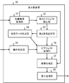
- FIG. 8 is a diagram conceptually illustrating a processing configuration example of the display-side device 30 in the first embodiment.
- the display-side device 30 in the first embodiment includes a line-of-sight image acquisition unit 31, a second object detection unit 32, a second reference setting unit 33, a virtual data generation unit 34, an operation specification unit 35, an object processing unit 36, and an image composition unit. 37, a display processing unit 38, and the like.
- Each of these processing units is realized, for example, by executing a program stored in the memory 3 by the CPU 2.
- the program may be installed from a portable recording medium such as a CD (Compact Disc) or a memory card or another computer on the network via the input / output I / F 5 and stored in the memory 3. Good.
- CD Compact Disc
- the line-of-sight image acquisition unit 31 acquires the line-of-sight image of the user from the HMD 9.
- This line-of-sight image may show a specific part of the user. This specific part is also the same as the specific part to be detected by the sensor-side device 10.
- the line-of-sight image acquisition unit 31 acquires line-of-sight images corresponding to the left eye and the right eye, respectively. Note that each processing unit performs the same processing on both line-of-sight images corresponding to the left eye and the right eye, and therefore, in the following description, a single line-of-sight image will be described.
- the second object detection unit 32 detects a known common real object from the line-of-sight image acquired by the line-of-sight image acquisition unit 31.
- This common real object may be the same as the object detected by the sensor-side device 10 described above, a specific part of the object is used in the sensor-side device 10, and the entire object is used on the HMD 9 side. The form used may be sufficient. Since the processing of the second object detection unit 32 is the same as that of the first object detection unit 12 of the sensor-side device 10 described above, detailed description thereof is omitted here. Note that the common real object included in the line-of-sight image has a different imaging direction from the common real object included in the 3D information obtained by the 3D sensor 8.
- the second reference setting unit 33 sets the 3D coordinate space set by the first reference setting unit 13 of the sensor side device 10 based on the common real object detected by the second object detection unit 32, and the HMD 9 Are calculated respectively. Since the processing of the second reference setting unit 33 is also the same as that of the first reference setting unit 13 of the sensor side device 10, detailed description thereof is omitted here. Since the 3D coordinate space set by the second reference setting unit 33 is also set based on the same common real object as the 3D coordinate space set by the first reference setting unit 13 of the sensor-side device 10, as a result, 3D The coordinate space is shared between the sensor side device 10 and the display side device 30.
- the virtual data generation unit 34 generates virtual 3D object data arranged in a 3D coordinate space shared with the sensor side device 10 by the second reference setting unit 33.
- the virtual data generation unit 34 may generate virtual 3D space data in which the virtual 3D object is arranged together with the virtual 3D object data.
- the operation specifying unit 35 receives the 3D pointing position and state information on the 3D coordinate space related to the specific part of the user from the sensor side device 10, and based on the combination of the state information and the change of the 3D pointing position, One predetermined process executed by the object processing unit 36 is specified from the predetermined processes. The change in the 3D pointing position is calculated from the relationship with the 3D pointing position obtained in the previous process. When a plurality of specific parts (for example, both hands) are used, the operation specifying unit 35 calculates the positional relationship between the plurality of specific parts from the plurality of 3D pointing positions acquired from the sensor side device 10.
- one predetermined process is specified from the plurality of predetermined processes based on the calculated positional change between the plurality of specific parts and the plurality of state information.
- the plurality of predetermined processes include a moving process, a rotating process, an enlarging process, a reducing process, and a function menu display data adding process.
- the operation specifying unit 35 corresponds to the linear movement amount of the one hand while the user's one hand is maintaining the specific state (the predetermined shape) (for example, the gripped state). Specify the process to move by the distance.
- the operation specifying unit 35 changes the distance between the two hands in a state where the user's both hands maintain a specific state (the predetermined shape) (for example, a gripped state).
- An enlargement process using the position of one hand of the user as a reference point is specified with an enlargement ratio corresponding to the amount. Note that the present embodiment does not limit the predetermined process itself specified by the operation specifying unit 35.
- the operation specifying unit 35 holds an ID for identifying each predetermined process as described above, and specifies the predetermined process by selecting an ID corresponding to the predetermined process.
- the operation specifying unit 35 causes the object processing unit 36 to execute the predetermined processing by passing the selected ID, the 3D pointing position in the 3D coordinate space, and the like to the object processing unit 36.
- the object processing unit 36 applies the predetermined process specified by the operation specifying unit 35 to the virtual 3D object data generated by the virtual data generating unit 34.
- the object processing unit 36 is realized so as to be able to execute a plurality of supported predetermined processes.
- the image composition unit 37 Based on the position and orientation of the HMD 9 calculated by the second reference setting unit 33 and the 3D coordinate space, the image composition unit 37 applies predetermined processing to the line-of-sight image acquired by the line-of-sight image acquisition unit 31 by the object processing unit 36. A virtual 3D object corresponding to the applied virtual 3D object data is synthesized. It should be noted that since a known method used in augmented reality (AR) or the like may be used for the composition processing by the image composition unit 37, description thereof is omitted here.
- AR augmented reality
- the display processing unit 38 causes the HMD 9 to display the synthesized image obtained by the image synthesizing unit 37.
- the display processing unit 38 displays each combined image combined with each line-of-sight image on the display 9c of the HMD 9 and 9d is displayed.
- FIG. 9 is a diagram illustrating an example of a composite image displayed on the HMD 9.
- the composite image shown in the example of FIG. 9 is formed from a spherical virtual 3D object VO and a line-of-sight image (including a desk VA) including one hand of the user.
- the user can freely operate the virtual 3D object included in the image by moving his / her hand while viewing the image on the HMD 9.
- FIG. 10 is a sequence chart showing an operation example of the 3D-UI device 1 in the first embodiment.
- the sensor side device 10 sequentially acquires 3D information from the 3D sensor 8 (S101).
- the sensor side device 10 operates as follows with respect to the 3D information of a predetermined frame rate.
- the sensor side device 10 detects a common real object from the 3D information (S102). Subsequently, the sensor-side device 10 sets a 3D coordinate space based on the detected common real object, and calculates the position and orientation of the 3D sensor 8 in the 3D coordinate space (S103).
- the sensor-side device 10 calculates the 3D pointing position of the specific part of the user using the 3D information (S104). Furthermore, the sensor side device 10 sets the 3D pointing position calculated in the step (S104) in the step (S103) based on the position and orientation of the 3D sensor 8 calculated in the step (S103) and the 3D coordinate space. The 3D pointing position on the 3D coordinate space is converted (S105).
- the sensor side device 10 adjusts the 3D pointing position converted in the step (S105) according to the shape change of the specific part of the user (S106). Details of the step (S106) will be described later. Further, the sensor-side device 10 specifies the state of the specific part based on the shape of the specific part of the user, and acquires state information (S107).
- the sensor side device 10 sends the 3D pointing position obtained in the step (S106) and the state information obtained in the step (S107) to the display side device 30 with respect to the specific part of the user (S108).
- the display-side device 30 is sequentially acquiring the line-of-sight images from the HMD 9 (S111) asynchronously with the acquisition of the 3D information (S101).
- the display-side device 30 operates as follows for the line-of-sight image having a predetermined frame rate.
- the display-side device 30 detects a common real object from the line-of-sight image (S112). Subsequently, the display-side device 30 sets a 3D coordinate space based on the detected common real object, and calculates the position and orientation of the HMD 9 in the 3D coordinate space (S113).
- the display side device 30 generates virtual 3D object data arranged in the set 3D coordinate space (S114).
- the display-side device 30 When the display-side device 30 receives the 3D pointing position and state information related to the specific part of the user from the sensor-side device 10 (S115), the display-side device 30 changes the 3D pointing position and the state information of the specific part according to the combination of the user A predetermined process corresponding to the gesture is specified (S116). When there are a plurality of specific parts, the display-side device 30 specifies a predetermined process according to a combination of a change in the positional relationship between the plurality of specific parts and a plurality of state information.
- the display-side device 30 applies the predetermined process specified in the step (S116) to the virtual 3D object data generated in the step (S114) (S117). Subsequently, the display-side device 30 synthesizes the virtual 3D object corresponding to the virtual 3D object data that has undergone the predetermined processing and the line-of-sight image (S118), and generates display data.
- the display-side device 30 displays the image obtained by the synthesis on the HMD 9 (S119).
- FIG. 10 shows an example in which the acquisition of 3D information (S101) and the acquisition of state information (S107) are performed sequentially for convenience of explanation, but the state information of a specific part can be obtained from other than 3D information. In some cases, steps (S101) and (S107) are performed in parallel.
- FIG. 10 shows an example in which the steps (S102) and (S103) are executed at a predetermined frame rate of 3D information. However, the steps (S102) and (S103) are executed only during calibration. May be.
- step (S 115) to step (S 117) on information related to a specific part of the user sent from the sensor-side device 10 and virtual 3D object data generation processing (step (S 112)).
- step (S 112) virtual 3D object data generation processing
- FIG. 11 is a flowchart showing details of the step (S106) shown in FIG.
- the sensor-side device 10 detects a change start, a change end, or a recovery change for the shape of the specific part of the user.
- the sensor-side device 10 detects the change start of the shape of the specific part of the user (S121; YES)
- the 3D pointing position corresponding to the start of change in the 3D pointing position converted in the step (S105) of FIG. Is held (S122).
- the sensor side device 10 When detecting the end of the change in the shape of the specific part of the user (S121; NO, 123; YES), the sensor side device 10 responds to the end of the change in the 3D pointing position converted in the step (S105) of FIG.
- the 3D pointing position to be identified is specified (S124).
- the sensor-side device 10 calculates a difference between the 3D pointing position corresponding to the end of the change and the 3D pointing position held in the step (S122) (S125).
- the sensor side device 10 adjusts the 3D pointing position corresponding to the end of the change by using the calculated difference (S129).
- the sensor side apparatus 10 detects the recovery
- the sensor-side device 10 When none of the change start, change end, and recovery change is detected for the shape of the specific part of the user (S121; NO, S123; NO, S126; NO), the sensor-side device 10 is holding the 3D pointing position. It is determined whether or not (S128). When the 3D pointing position is being held (S128; YES), the sensor-side device 10 uses the difference calculated in step (S125) to adjust the 3D pointing position converted in step (S105) in FIG. (S129). Accordingly, the 3D pointing position is adjusted while the shape of the specific part of the user maintains at least the shape at the end of the change.
- the sensor-side device 10 uses the 3D pointing position converted in the step (S105) in FIG. 10 without adjustment.
- a user's line-of-sight image in which a specific part (hand or the like) used for the pointing operation is captured is acquired, and an image obtained by combining the virtual 3D object with the line-of-sight image is a video see-through method. Is displayed in the user's field of view.
- the state information regarding the change in the 3D pointing position of the specific part of the user and the shape of the specific part is acquired, and the predetermined process specified from the combination is performed on the virtual 3D object. Applied.
- the user can feel as if he / she is operating the virtual 3D object at his / her specific part. That is, according to the first embodiment, the user can be provided with an intuitive operational feeling for the virtual 3D object.
- the pointing position after the end of the change is adjusted using the deviation of the pointing position corresponding to the specific part before and after the change of the shape of the specific part of the user used for the pointing operation.
- the held 3D pointing position is released, and the 3D pointing position is not adjusted after the release.
- the 3D pointing position is not adjusted in the process of changing from a state where the hand is held (the predetermined shape) to a state where the hand is opened. This is because the displacement of the pointing position corresponding to the specific part is eliminated, and the position adjustment is not necessary.
- the pointing operation of the user is more intuitively recognized by eliminating the displacement of the pointing position before and after the specific gesture and stopping the position adjustment accompanying the shape change of the specific area.
- the operation can be performed.
- such an effect is not limited to a form in which a specific part of the user is copied in the line-of-sight image and a virtual 3D object to be operated is synthesized. This is because the user may operate the operation target at his / her specific part without directing his / her line of sight toward the operation target. Even in such a case, according to the first embodiment, the displacement of the pointing position corresponding to the specific part can be similarly eliminated.
- the HMD 9 is used, and a mode in which the operation of the virtual 3D object is enabled by the operation of the specific part of the user shown in the user line-of-sight image is exemplified.
- the present invention can also be applied to a mode in which a virtual 3D object can be operated by an operation of a specific part of a user shown in the user image taken from the opposite side instead of the user line-of-sight image. This is because even in such a form, the displacement of the pointing position before and after the specific gesture can occur.
- the 3D-UI device 1 in the second embodiment will be described focusing on the content different from the first embodiment. In the following description, the same contents as those in the first embodiment are omitted as appropriate.
- the 3D-UI device 1 in the second embodiment includes only the sensor-side device 10 and displays the composite image on a display unit connected to the input / output I / F 5 of the sensor-side device 10.
- FIG. 12 is a diagram conceptually illustrating a processing configuration example of the 3D-UI apparatus 1 in the second embodiment.
- the processing configuration of the 3D-UI device 1 in the second embodiment includes a first object detection unit 12, a first reference setting unit 13, a position calculation unit 14, a transmission unit 16, a line-of-sight image acquisition unit 31, and a second object detection unit 32.
- the point from which the 2nd standard setting part 33 is removed differs from a 1st embodiment.
- the second embodiment is different from the first embodiment in that processing is performed based on a 3D pointing position corresponding to the camera coordinate system of the 3D sensor 8.
- the user moves his / her specific part on the image while viewing his / her image captured from the opposite side displayed on the display unit of the sensor-side device 10.
- a virtual 3D object appearing on the screen can be manipulated.
- the sensor side device 10 according to the second embodiment may display a pseudo user image instead of the user image.
- the pointing position is shifted before and after the specific gesture, and this difference is determined by using the difference between the 3D pointing position corresponding to the end of the change and the 3D pointing position corresponding to the held start of the change. It can be solved by adjusting the position.
- the position of the specific part of the user used for the pointing operation is specified by the three-dimensional coordinate system, but may be specified by the two-dimensional coordinate system (third embodiment).
- the sensor-side device 10 in the third embodiment has a 2D sensor such as an imaging device for 2D images, an infrared sensor, or the like instead of the 3D sensor 8.
- the 3D information acquisition unit 11 is replaced with a 2D information acquisition unit, and the 2D information acquisition unit acquires 2D information that can be obtained from the 2D sensor and that can identify a specific part of the user.
- the position calculation unit 14 sequentially calculates the 2D pointing position of the specific part of the user, and the 2D pointing position is adjusted in accordance with the shape change of the specific part.
- the virtual data generation unit 34 may generate 2D virtual object data.
- the image of a specific part of a user does not need to be contained in 2D information.
- the sensor-side device 10 does not have to include the image composition unit 37, and displays 2D virtual object data subjected to predetermined processing on the display unit.
- the 2D pointing position may be displaced before and after the specific gesture. This shift can be eliminated by adjusting the position using the difference between the 2D pointing position corresponding to the end of the change and the 2D pointing position corresponding to the held start of the change.
- the 3D pointing position converted from the camera coordinate system to the 3D coordinate system set based on the common real object is adjusted, but the 3D pointing position of the camera coordinate system before conversion is adjusted. Also good.
- the adjusted 3D pointing position is converted into a 3D coordinate system set based on the common real object.
- the step (S106) of FIG. 10 is executed after the step (S104) and before the step (S105).
- the adjustment of the 3D pointing position or the 2D pointing position in each of the above-described embodiments may be further performed as follows.
- the change detection unit 21 measures the change time from the start of change to the end of change, and the position holding unit 22 sets the pointing position to be held when the measured change time is larger than a predetermined threshold.
- the position adjustment unit 24 stops the adjustment of the pointing position in response to the release of the pointing position by the position holding unit 22.
- the position holding unit 22 releases the held pointing position when the difference calculated by the calculation unit 23 is larger than a predetermined threshold, and the position adjusting unit 24 sets the pointing position by the position holding unit 22. The adjustment of the pointing position is stopped in response to the release of.
- a position acquisition unit that sequentially acquires a pointing position indicating at least one representative position of the specific part of the user used for the pointing operation;
- a change detection unit that detects a change start and a change end of the specific part of the user to a predetermined shape;
- a position holding unit that holds a pointing position corresponding to the start of the change detected by the change detection unit;
- the pointing position corresponding to the end of the change detected by the change detection unit is specified, and the specified pointing position and the pointing position held by the position holding unit
- a user interface device comprising:
- the change detection unit detects a recovery change in the recovery direction from the predetermined shape of the shape of the specific part of the user,
- the position holding unit releases the held pointing position in response to detection of the recovery change by the change detection unit,
- the position adjusting unit stops adjusting the pointing position acquired by the position acquiring unit in response to the release of the pointing position by the position holding unit;
- the user interface device according to attachment 1.
- the change detection unit measures a change time from detection of the change start to detection of the change end, The position holding unit releases the held pointing position when the change time is greater than a predetermined threshold; The position adjusting unit stops adjusting the pointing position acquired by the position acquiring unit in response to the release of the pointing position by the position holding unit;
- the user interface device according to appendix 1 or 2.
- the position holding unit releases the held pointing position when the difference calculated by the calculation unit is larger than a predetermined threshold;
- the position adjusting unit stops adjusting the pointing position acquired by the position acquiring unit in response to the release of the pointing position by the position holding unit;
- the user interface device according to any one of appendices 1 to 3.
- Appendix 5 In a user interface method executed by at least one computer, Sequentially acquiring a pointing position indicating at least one representative position of the specific part of the user used for the pointing operation; Detecting the change start and change end of the specific part of the user to a predetermined shape; Among the sequentially acquired pointing positions, the pointing position corresponding to the detected change start time is held, Among the obtained pointing positions, a pointing position corresponding to the detected change end time is specified, Calculating a difference between the identified pointing position and the held pointing position; Adjusting the obtained pointing position using the calculated difference;
- a user interface method comprising:
- Appendix 7 Measure the change time from the detection of the change start to the detection of the change end, If the change time is greater than a predetermined threshold, release the held pointing position; Stopping the adjustment of the obtained pointing position in response to the release of the pointing position;
- the user interface method is: Sequentially acquiring a pointing position indicating at least one representative position of the specific part of the user used for the pointing operation; Detecting the change start and change end of the specific part of the user to a predetermined shape; Among the sequentially acquired pointing positions, the pointing position corresponding to the detected change start time is held, Among the obtained pointing positions, a pointing position corresponding to the detected change end time is specified, Calculating a difference between the identified pointing position and the held pointing position; Adjusting the obtained pointing position using the calculated difference; A program that includes that.
- the user interface method is: Detecting a recovery change in the recovery direction from the predetermined shape of the shape of the specific part of the user; In response to detection of the recovery change by the change detection unit, the held pointing position is released, Stopping the adjustment of the pointing position in response to the release of the pointing position;
- the user interface method is: Measure the change time from the detection of the change start to the detection of the change end, If the change time is greater than a predetermined threshold, release the held pointing position; Stopping the adjustment of the obtained pointing position in response to the release of the pointing position;
- the user interface method is: If the calculated difference is greater than a predetermined threshold, release the held pointing position; Stopping the adjustment of the obtained pointing position in response to the release of the pointing position;
- Appendix 13 A computer-readable recording medium on which the program according to any one of appendices 9 to 12 is recorded.
Abstract
Description
〔装置構成〕
図4は、第1実施形態における3次元ユーザインタフェース装置(以降、3D-UI装置と表記する)1のハードウェア構成例を概念的に示す図である。第1実施形態における3D-UI装置1は、大きく、センサ側構成と表示側構成とを持つ。センサ側構成は、3次元センサ(以降、3Dセンサと表記する)8及びセンサ側装置10から形成される。表示側構成は、ヘッドマウントディスプレイ(以降、HMDと表記する)9及び表示側装置30から形成される。以降、3次元を3Dと適宜省略して表記する。
〈センサ側装置〉
図7は、第1実施形態におけるセンサ側装置10の処理構成例を概念的に示す図である。第1実施形態におけるセンサ側装置10は、3D情報取得部11、第1オブジェクト検出部12、第1基準設定部13、位置算出部14、状態取得部15、送信部16、変化検出部21、位置保持部22、算出部23、位置調節部24などを有する。これら各処理部は、例えば、CPU2によりメモリ3に格納されるプログラムが実行されることにより実現される。また、当該プログラムは、例えば、CD(Compact Disc)、メモリカード等のような可搬型記録媒体やネットワーク上の他のコンピュータから入出力I/F5を介してインストールされ、メモリ3に格納されてもよい。
図8は、第1実施形態における表示側装置30の処理構成例を概念的に示す図である。第1実施形態における表示側装置30は、視線画像取得部31、第2オブジェクト検出部32、第2基準設定部33、仮想データ生成部34、操作特定部35、オブジェクト処理部36、画像合成部37、表示処理部38などを有する。これら各処理部は、例えば、CPU2によりメモリ3に格納されるプログラムが実行されることにより実現される。また、当該プログラムは、例えば、CD(Compact Disc)、メモリカード等のような可搬型記録媒体やネットワーク上の他のコンピュータから入出力I/F5を介してインストールされ、メモリ3に格納されてもよい。
以下、第1実施形態におけるユーザインタフェース方法について図10を用いて説明する。図10は、第1実施形態における3D-UI装置1の動作例を示すシーケンスチャートである。
続いて、センサ側装置10は、検出された共通実オブジェクトに基づいて、3D座標空間を設定し、かつ、この3D座標空間における3Dセンサ8の位置及び向きを算出する(S103)。
センサ側装置10は、ユーザの特定部位の形状について、変化開始、変化終了又は回復変化を検出する。センサ側装置10は、ユーザの特定部位の形状の変化開始を検出すると(S121;YES)、図10の工程(S105)で変換される3Dポインティング位置の中の、変化開始時に対応する3Dポインティング位置を保持する(S122)。
上述したように、第1実施形態では、ポインティング操作に用いられる特定部位(手など)が写されたユーザの視線画像が取得され、その視線画像に仮想3Dオブジェクトが合成された画像がビデオシースルー方式でユーザの視野内に表示される。その上で、第1実施形態では、ユーザの当該特定部位の3Dポインティング位置の変化とその特定部位の形状に関する状態情報が取得され、それらの組み合わせから特定される所定処理が、仮想3Dオブジェクトに対して適用される。これにより、第1実施形態によれば、ユーザは、仮想3Dオブジェクトを自身の特定部位で操作しているかのように感じることができる。即ち、第1実施形態によれば、ユーザに、仮想3Dオブジェクトに対する直感的操作感を与えることができる。
上述の第1実施形態では、HMD9が用いられ、ユーザ視線画像に写るユーザの特定部位の動作により、仮想3Dオブジェクトの操作を可能とする形態が例示された。しかしながら、本発明は、ユーザ視線画像ではなく、向かい側から写されたユーザ画像に写るユーザの特定部位の動作により、仮想3Dオブジェクトの操作を可能とする形態にも適用可能である。このような形態においても、特定ジェスチャの前後でのポインティング位置のずれは起こり得るからである。以下、第2実施形態における3D-UI装置1について、第1実施形態と異なる内容を中心に説明する。以下の説明では、第1実施形態と同様の内容については適宜省略する。
上述の第2実施形態では、ポインティング操作に用いられるユーザの特定部位の位置が、3次元座標系により特定されたが、2次元座標系により特定されるようにしてもよい(第3実施形態)。第3実施形態におけるセンサ側装置10は、3Dセンサ8に替え、2D画像の撮像装置、赤外線センサなどのような2Dセンサを有する。3D情報取得部11は、2D情報取得部に替えられ、2D情報取得部は、2Dセンサから得られる、ユーザの特定部位を特定し得る2D情報を取得する。これにより、位置算出部14が、ユーザの特定部位の2Dポインティング位置を逐次算出し、この2Dポインティング位置が当該特定部位の形状変化に伴って調節される。
上述の第1実施形態では、カメラ座標系から共通実オブジェクトに基づき設定される3D座標系へ変換された3Dポインティング位置が調節されたが、変換前のカメラ座標系の3Dポインティング位置が調節されてもよい。この場合には、調節された3Dポインティング位置が共通実オブジェクトに基づき設定される3D座標系へ変換される。この場合、図10の工程(S106)は、工程(S104)の後、かつ、工程(S105)の前に実行される。
ポインティング操作に用いられるユーザの特定部位の少なくとも1つの代表的な位置を示すポインティング位置を逐次取得する位置取得部と、
前記ユーザの前記特定部位の所定形状への変化開始及び変化終了を検出する変化検出部と、
前記位置取得部により逐次取得されるポインティング位置のうち、前記変化検出部により検出される前記変化開始時に対応するポインティング位置を保持する位置保持部と、
前記位置取得部により取得されるポインティング位置のうち、前記変化検出部により検出される前記変化終了時に対応するポインティング位置を特定し、該特定されたポインティング位置と前記位置保持部で保持されるポインティング位置との差を算出する算出部と、
前記算出部で算出される差を用いて、前記位置取得部により取得されるポインティング位置を調節する位置調節部と、
を備えるユーザインタフェース装置。
前記変化検出部は、前記ユーザの前記特定部位の形状の、前記所定形状から回復方向への回復変化を検出し、
前記位置保持部は、前記変化検出部による前記回復変化の検出に応じて、保持されるポインティング位置を解放し、
前記位置調節部は、前記位置保持部によるポインティング位置の解放に応じて、前記位置取得部で取得されるポインティング位置の調節を停止する、
付記1に記載のユーザインタフェース装置。
前記変化検出部は、前記変化開始の検出から前記変化終了の検出までの変化時間を計測し、
前記位置保持部は、前記変化時間が所定閾値より大きい場合に、保持されるポインティング位置を解放し、
前記位置調節部は、前記位置保持部によるポインティング位置の解放に応じて、前記位置取得部で取得されるポインティング位置の調節を停止する、
付記1又は2に記載のユーザインタフェース装置。
前記位置保持部は、前記算出部により算出される前記差が所定閾値より大きい場合に、保持されるポインティング位置を解放し、
前記位置調節部は、前記位置保持部によるポインティング位置の解放に応じて、前記位置取得部で取得されるポインティング位置の調節を停止する、
付記1から3のいずれか1つに記載のユーザインタフェース装置。
少なくとも1つのコンピュータにより実行されるユーザインタフェース方法において、
ポインティング操作に用いられるユーザの特定部位の少なくとも1つの代表的な位置を示すポインティング位置を逐次取得し、
前記ユーザの前記特定部位の所定形状への変化開始及び変化終了を検出し、
前記逐次取得されるポインティング位置のうち、前記検出される変化開始時に対応するポインティング位置を保持し、
前記取得されるポインティング位置のうち、前記検出される変化終了時に対応するポインティング位置を特定し、
前記特定されたポインティング位置と前記保持されるポインティング位置との差を算出し、
前記算出される差を用いて、前記取得されるポインティング位置を調節する、
ことを含むユーザインタフェース方法。
前記ユーザの前記特定部位の形状の、前記所定形状から回復方向への回復変化を検出し、
前記変化検出部による前記回復変化の検出に応じて、保持されるポインティング位置を解放し、
前記ポインティング位置の解放に応じて、前記ポインティング位置の調節を停止する、
ことを更に含む付記5に記載のユーザインタフェース方法。
前記変化開始の検出から前記変化終了の検出までの変化時間を計測し、
前記変化時間が所定閾値より大きい場合に、保持されるポインティング位置を解放し、
前記ポインティング位置の解放に応じて、前記取得されるポインティング位置の調節を停止する、
ことを更に含む付記5又は6に記載のユーザインタフェース方法。
前記算出される差が所定閾値より大きい場合に、保持されるポインティング位置を解放し、
前記ポインティング位置の解放に応じて、前記取得されるポインティング位置の調節を停止する、
ことを更に含む付記5から7のいずれか1つに記載のユーザインタフェース方法。
少なくとも1つのコンピュータにユーザインタフェース方法を実行させるプログラムにおいて、
前記ユーザインタフェース方法は、
ポインティング操作に用いられるユーザの特定部位の少なくとも1つの代表的な位置を示すポインティング位置を逐次取得し、
前記ユーザの前記特定部位の所定形状への変化開始及び変化終了を検出し、
前記逐次取得されるポインティング位置のうち、前記検出される変化開始時に対応するポインティング位置を保持し、
前記取得されるポインティング位置のうち、前記検出される変化終了時に対応するポインティング位置を特定し、
前記特定されたポインティング位置と前記保持されるポインティング位置との差を算出し、
前記算出される差を用いて、前記取得されるポインティング位置を調節する、
ことを含むプログラム。
前記ユーザインタフェース方法は、
前記ユーザの前記特定部位の形状の、前記所定形状から回復方向への回復変化を検出し、
前記変化検出部による前記回復変化の検出に応じて、保持されるポインティング位置を解放し、
前記ポインティング位置の解放に応じて、前記ポインティング位置の調節を停止する、
ことを更に含む付記9に記載のプログラム。
前記ユーザインタフェース方法は、
前記変化開始の検出から前記変化終了の検出までの変化時間を計測し、
前記変化時間が所定閾値より大きい場合に、保持されるポインティング位置を解放し、
前記ポインティング位置の解放に応じて、前記取得されるポインティング位置の調節を停止する、
ことを更に含む付記9又は10に記載のプログラム。
前記ユーザインタフェース方法は、
前記算出される差が所定閾値より大きい場合に、保持されるポインティング位置を解放し、
前記ポインティング位置の解放に応じて、前記取得されるポインティング位置の調節を停止する、
ことを更に含む付記9から11のいずれか1つに記載のプログラム。
付記9から12のいずれか1つに記載のプログラムを記録したコンピュータが読み取り可能な記録媒体。
Claims (9)
- ポインティング操作に用いられるユーザの特定部位の少なくとも1つの代表的な位置を示すポインティング位置を逐次取得する位置取得部と、
前記ユーザの前記特定部位の所定形状への変化開始及び変化終了を検出する変化検出部と、
前記位置取得部により逐次取得されるポインティング位置のうち、前記変化検出部により検出される前記変化開始時に対応するポインティング位置を保持する位置保持部と、
前記位置取得部により取得されるポインティング位置のうち、前記変化検出部により検出される前記変化終了時に対応するポインティング位置を特定し、該特定されたポインティング位置と前記位置保持部で保持されるポインティング位置との差を算出する算出部と、
前記算出部で算出される差を用いて、前記位置取得部により取得されるポインティング位置を調節する位置調節部と、
を備えるユーザインタフェース装置。 - 前記変化検出部は、前記ユーザの前記特定部位の形状の、前記所定形状から回復方向への回復変化を検出し、
前記位置保持部は、前記変化検出部による前記回復変化の検出に応じて、保持されるポインティング位置を解放し、
前記位置調節部は、前記位置保持部によるポインティング位置の解放に応じて、前記位置取得部で取得されるポインティング位置の調節を停止する、
請求項1に記載のユーザインタフェース装置。 - 前記変化検出部は、前記変化開始の検出から前記変化終了の検出までの変化時間を計測し、
前記位置保持部は、前記変化時間が所定閾値より大きい場合に、保持されるポインティング位置を解放し、
前記位置調節部は、前記位置保持部によるポインティング位置の解放に応じて、前記位置取得部で取得されるポインティング位置の調節を停止する、
請求項1又は2に記載のユーザインタフェース装置。 - 前記位置保持部は、前記算出部により算出される前記差が所定閾値より大きい場合に、保持されるポインティング位置を解放し、
前記位置調節部は、前記位置保持部によるポインティング位置の解放に応じて、前記位置取得部で取得されるポインティング位置の調節を停止する、
請求項1から3のいずれか1項に記載のユーザインタフェース装置。 - 少なくとも1つのコンピュータが、
ポインティング操作に用いられるユーザの特定部位の少なくとも1つの代表的な位置を示すポインティング位置を逐次取得し、
前記ユーザの前記特定部位の所定形状への変化開始及び変化終了を検出し、
前記逐次取得されるポインティング位置のうち、前記検出される変化開始時に対応するポインティング位置を保持し、
前記取得されるポインティング位置のうち、前記検出される変化終了時に対応するポインティング位置を特定し、
前記特定されたポインティング位置と前記保持されるポインティング位置との差を算出し、
前記算出される差を用いて、前記取得されるポインティング位置を調節する、
ことを含むユーザインタフェース方法。 - 前記少なくとも1つのコンピュータが、
前記ユーザの前記特定部位の形状の、前記所定形状から回復方向への回復変化を検出し、
前記変化検出部による前記回復変化の検出に応じて、保持されるポインティング位置を解放し、
前記ポインティング位置の解放に応じて、前記ポインティング位置の調節を停止する、
ことを更に含む請求項5に記載のユーザインタフェース方法。 - 前記少なくとも1つのコンピュータが、
前記変化開始の検出から前記変化終了の検出までの変化時間を計測し、
前記変化時間が所定閾値より大きい場合に、保持されるポインティング位置を解放し、
前記ポインティング位置の解放に応じて、前記取得されるポインティング位置の調節を停止する、
ことを更に含む請求項5又は6に記載のユーザインタフェース方法。 - 前記少なくとも1つのコンピュータが、
前記算出される差が所定閾値より大きい場合に、保持されるポインティング位置を解放し、
前記ポインティング位置の解放に応じて、前記取得されるポインティング位置の調節を停止する、
ことを更に含む請求項5から7のいずれか1項に記載のユーザインタフェース方法。 - 請求項5から8のいずれか1項に記載のユーザインタフェース方法を少なくとも1つのコンピュータに実行させるプログラム。
Priority Applications (4)
| Application Number | Priority Date | Filing Date | Title |
|---|---|---|---|
| EP13843524.3A EP2905676A4 (en) | 2012-10-05 | 2013-06-20 | USER INTERFACE DEVICE AND USER INTERFACE PROCEDURE |
| JP2014539626A JP5863984B2 (ja) | 2012-10-05 | 2013-06-20 | ユーザインタフェース装置及びユーザインタフェース方法 |
| US14/433,456 US9760180B2 (en) | 2012-10-05 | 2013-06-20 | User interface device and user interface method |
| CN201380052301.2A CN104704449B (zh) | 2012-10-05 | 2013-06-20 | 用户界面设备和用户界面方法 |
Applications Claiming Priority (2)
| Application Number | Priority Date | Filing Date | Title |
|---|---|---|---|
| JP2012-222884 | 2012-10-05 | ||
| JP2012222884 | 2012-10-05 |
Publications (1)
| Publication Number | Publication Date |
|---|---|
| WO2014054317A1 true WO2014054317A1 (ja) | 2014-04-10 |
Family
ID=50434653
Family Applications (1)
| Application Number | Title | Priority Date | Filing Date |
|---|---|---|---|
| PCT/JP2013/066941 WO2014054317A1 (ja) | 2012-10-05 | 2013-06-20 | ユーザインタフェース装置及びユーザインタフェース方法 |
Country Status (5)
| Country | Link |
|---|---|
| US (1) | US9760180B2 (ja) |
| EP (1) | EP2905676A4 (ja) |
| JP (1) | JP5863984B2 (ja) |
| CN (1) | CN104704449B (ja) |
| WO (1) | WO2014054317A1 (ja) |
Cited By (3)
| Publication number | Priority date | Publication date | Assignee | Title |
|---|---|---|---|---|
| JPWO2016103521A1 (ja) * | 2014-12-26 | 2017-09-14 | 株式会社ニコン | 検出装置およびプログラム |
| JPWO2016103520A1 (ja) * | 2014-12-26 | 2017-09-14 | 株式会社ニコン | 検出装置、電子機器、検出方法およびプログラム |
| EP3274965A4 (en) * | 2015-03-24 | 2018-08-15 | Intel Corporation | Augmentation modification based on user interaction with augmented reality scene |
Families Citing this family (1)
| Publication number | Priority date | Publication date | Assignee | Title |
|---|---|---|---|---|
| KR20140010616A (ko) * | 2012-07-16 | 2014-01-27 | 한국전자통신연구원 | 3d 가상 객체에 대한 조작 처리 장치 및 방법 |
Citations (5)
| Publication number | Priority date | Publication date | Assignee | Title |
|---|---|---|---|---|
| JP2003337962A (ja) * | 2002-05-17 | 2003-11-28 | Seiko Epson Corp | 画像処理装置および画像処理方法、ならびに、画像処理プログラムおよびその記録媒体 |
| WO2006041097A1 (ja) * | 2004-10-12 | 2006-04-20 | Nippon Telegraph And Telephone Corporation | 3次元ポインティング方法、3次元表示制御方法、3次元ポインティング装置、3次元表示制御装置、3次元ポインティングプログラム、及び3次元表示制御プログラム |
| JP2010522380A (ja) * | 2007-03-19 | 2010-07-01 | ゼブラ・イメージング・インコーポレイテッド | ユーザ入力により動的3次元ディスプレイをアップデートするシステム及び方法 |
| WO2011158605A1 (ja) * | 2010-06-15 | 2011-12-22 | 日産自動車株式会社 | 情報表示装置、及び、オンスクリーンボタンの移動操作方法 |
| JP2012137989A (ja) | 2010-12-27 | 2012-07-19 | Sony Computer Entertainment Inc | ジェスチャ操作入力処理装置およびジェスチャ操作入力処理方法 |
Family Cites Families (12)
| Publication number | Priority date | Publication date | Assignee | Title |
|---|---|---|---|---|
| WO2002073955A1 (en) * | 2001-03-13 | 2002-09-19 | Canon Kabushiki Kaisha | Image processing apparatus, image processing method, studio apparatus, storage medium, and program |
| DE60325536D1 (de) | 2002-09-20 | 2009-02-12 | Nippon Telegraph & Telephone | Vorrichtung zum Erzeugen eines pseudo-dreidimensionalen Bildes |
| JP4262011B2 (ja) * | 2003-07-30 | 2009-05-13 | キヤノン株式会社 | 画像提示方法及び装置 |
| US7743348B2 (en) * | 2004-06-30 | 2010-06-22 | Microsoft Corporation | Using physical objects to adjust attributes of an interactive display application |
| US9772689B2 (en) * | 2008-03-04 | 2017-09-26 | Qualcomm Incorporated | Enhanced gesture-based image manipulation |
| JP5094663B2 (ja) * | 2008-09-24 | 2012-12-12 | キヤノン株式会社 | 位置姿勢推定用モデル生成装置、位置姿勢算出装置、画像処理装置及びそれらの方法 |
| KR101114750B1 (ko) * | 2010-01-29 | 2012-03-05 | 주식회사 팬택 | 다차원 영상을 이용한 사용자 인터페이스 장치 |
| JP5495821B2 (ja) * | 2010-01-29 | 2014-05-21 | キヤノン株式会社 | 画像形成装置及びその制御方法 |
| JP5499762B2 (ja) * | 2010-02-24 | 2014-05-21 | ソニー株式会社 | 画像処理装置、画像処理方法、プログラム及び画像処理システム |
| JP5732783B2 (ja) | 2010-09-02 | 2015-06-10 | ソニー株式会社 | 情報処理装置、情報処理装置の入力制御方法及びプログラム |
| US20120117514A1 (en) * | 2010-11-04 | 2012-05-10 | Microsoft Corporation | Three-Dimensional User Interaction |
| US8736583B2 (en) * | 2011-03-29 | 2014-05-27 | Intel Corporation | Virtual links between different displays to present a single virtual object |
-
2013
- 2013-06-20 WO PCT/JP2013/066941 patent/WO2014054317A1/ja active Application Filing
- 2013-06-20 US US14/433,456 patent/US9760180B2/en active Active
- 2013-06-20 EP EP13843524.3A patent/EP2905676A4/en not_active Withdrawn
- 2013-06-20 CN CN201380052301.2A patent/CN104704449B/zh active Active
- 2013-06-20 JP JP2014539626A patent/JP5863984B2/ja active Active
Patent Citations (5)
| Publication number | Priority date | Publication date | Assignee | Title |
|---|---|---|---|---|
| JP2003337962A (ja) * | 2002-05-17 | 2003-11-28 | Seiko Epson Corp | 画像処理装置および画像処理方法、ならびに、画像処理プログラムおよびその記録媒体 |
| WO2006041097A1 (ja) * | 2004-10-12 | 2006-04-20 | Nippon Telegraph And Telephone Corporation | 3次元ポインティング方法、3次元表示制御方法、3次元ポインティング装置、3次元表示制御装置、3次元ポインティングプログラム、及び3次元表示制御プログラム |
| JP2010522380A (ja) * | 2007-03-19 | 2010-07-01 | ゼブラ・イメージング・インコーポレイテッド | ユーザ入力により動的3次元ディスプレイをアップデートするシステム及び方法 |
| WO2011158605A1 (ja) * | 2010-06-15 | 2011-12-22 | 日産自動車株式会社 | 情報表示装置、及び、オンスクリーンボタンの移動操作方法 |
| JP2012137989A (ja) | 2010-12-27 | 2012-07-19 | Sony Computer Entertainment Inc | ジェスチャ操作入力処理装置およびジェスチャ操作入力処理方法 |
Non-Patent Citations (1)
| Title |
|---|
| See also references of EP2905676A4 |
Cited By (3)
| Publication number | Priority date | Publication date | Assignee | Title |
|---|---|---|---|---|
| JPWO2016103521A1 (ja) * | 2014-12-26 | 2017-09-14 | 株式会社ニコン | 検出装置およびプログラム |
| JPWO2016103520A1 (ja) * | 2014-12-26 | 2017-09-14 | 株式会社ニコン | 検出装置、電子機器、検出方法およびプログラム |
| EP3274965A4 (en) * | 2015-03-24 | 2018-08-15 | Intel Corporation | Augmentation modification based on user interaction with augmented reality scene |
Also Published As
| Publication number | Publication date |
|---|---|
| CN104704449B (zh) | 2017-09-12 |
| JP5863984B2 (ja) | 2016-02-17 |
| CN104704449A (zh) | 2015-06-10 |
| JPWO2014054317A1 (ja) | 2016-08-25 |
| US20150268735A1 (en) | 2015-09-24 |
| EP2905676A4 (en) | 2016-06-15 |
| US9760180B2 (en) | 2017-09-12 |
| EP2905676A1 (en) | 2015-08-12 |
Similar Documents
| Publication | Publication Date | Title |
|---|---|---|
| JP5936155B2 (ja) | 3次元ユーザインタフェース装置及び3次元操作方法 | |
| JP6057396B2 (ja) | 3次元ユーザインタフェース装置及び3次元操作処理方法 | |
| JP5871345B2 (ja) | 3次元ユーザインタフェース装置及び3次元操作方法 | |
| JP5843340B2 (ja) | 3次元環境共有システム及び3次元環境共有方法 | |
| WO2014147858A1 (ja) | 3次元ロック解除装置、3次元ロック解除方法及びプログラム | |
| TWI722280B (zh) | 用於多個自由度之控制器追蹤 | |
| KR101171660B1 (ko) | 증강현실의 포인팅 장치 | |
| US20170140552A1 (en) | Apparatus and method for estimating hand position utilizing head mounted color depth camera, and bare hand interaction system using same | |
| KR20130108643A (ko) | 응시 및 제스처 인터페이스를 위한 시스템들 및 방법들 | |
| KR102147430B1 (ko) | 가상 공간 멀티 터치 인터랙션 장치 및 방법 | |
| EP2814000A1 (en) | Image processing apparatus, image processing method, and program | |
| JP6344530B2 (ja) | 入力装置、入力方法、及びプログラム | |
| JP2012208705A (ja) | 画像操作装置、画像操作方法およびプログラム | |
| JP5863984B2 (ja) | ユーザインタフェース装置及びユーザインタフェース方法 | |
| KR101338958B1 (ko) | 멀티터치 단말기에서 가상물체의 3차원 움직임 조작시스템 및 방법 | |
| WO2019106862A1 (ja) | 操作案内システム | |
| JP2024056455A (ja) | 情報処理システム、情報処理方法、プログラム | |
| CN115803786A (zh) | 信息处理装置、信息处理方法和程序 |
Legal Events
| Date | Code | Title | Description |
|---|---|---|---|
| 121 | Ep: the epo has been informed by wipo that ep was designated in this application |
Ref document number: 13843524 Country of ref document: EP Kind code of ref document: A1 |
|
| ENP | Entry into the national phase |
Ref document number: 2014539626 Country of ref document: JP Kind code of ref document: A |
|
| REEP | Request for entry into the european phase |
Ref document number: 2013843524 Country of ref document: EP |
|
| WWE | Wipo information: entry into national phase |
Ref document number: 2013843524 Country of ref document: EP |
|
| WWE | Wipo information: entry into national phase |
Ref document number: 14433456 Country of ref document: US |
|
| NENP | Non-entry into the national phase |
Ref country code: DE |