WO2014054142A1 - 機器選定装置、及び機器選定処理プログラム、並びに機器選定処理方法 - Google Patents
機器選定装置、及び機器選定処理プログラム、並びに機器選定処理方法 Download PDFInfo
- Publication number
- WO2014054142A1 WO2014054142A1 PCT/JP2012/075711 JP2012075711W WO2014054142A1 WO 2014054142 A1 WO2014054142 A1 WO 2014054142A1 JP 2012075711 W JP2012075711 W JP 2012075711W WO 2014054142 A1 WO2014054142 A1 WO 2014054142A1
- Authority
- WO
- WIPO (PCT)
- Prior art keywords
- axis
- display
- driven mechanism
- selection
- driven
- Prior art date
- Legal status (The legal status is an assumption and is not a legal conclusion. Google has not performed a legal analysis and makes no representation as to the accuracy of the status listed.)
- Ceased
Links
Images








Classifications
-
- G—PHYSICS
- G05—CONTROLLING; REGULATING
- G05B—CONTROL OR REGULATING SYSTEMS IN GENERAL; FUNCTIONAL ELEMENTS OF SUCH SYSTEMS; MONITORING OR TESTING ARRANGEMENTS FOR SUCH SYSTEMS OR ELEMENTS
- G05B19/00—Program-control systems
- G05B19/02—Program-control systems electric
- G05B19/18—Numerical control [NC], i.e. automatically operating machines, in particular machine tools, e.g. in a manufacturing environment, so as to execute positioning, movement or co-ordinated operations by means of program data in numerical form
- G05B19/414—Structure of the control system, e.g. common controller or multiprocessor systems, interface to servo, programmable interface controller
- G05B19/4141—Structure of the control system, e.g. common controller or multiprocessor systems, interface to servo, programmable interface controller characterised by a controller or microprocessor per axis
-
- H—ELECTRICITY
- H02—GENERATION; CONVERSION OR DISTRIBUTION OF ELECTRIC POWER
- H02P—CONTROL OR REGULATION OF ELECTRIC MOTORS, ELECTRIC GENERATORS OR DYNAMO-ELECTRIC CONVERTERS; CONTROLLING TRANSFORMERS, REACTORS OR CHOKE COILS
- H02P5/00—Arrangements specially adapted for regulating or controlling the speed or torque of two or more electric motors
- H02P5/46—Arrangements specially adapted for regulating or controlling the speed or torque of two or more electric motors for speed regulation of two or more dynamo-electric motors in relation to one another
-
- H—ELECTRICITY
- H02—GENERATION; CONVERSION OR DISTRIBUTION OF ELECTRIC POWER
- H02P—CONTROL OR REGULATION OF ELECTRIC MOTORS, ELECTRIC GENERATORS OR DYNAMO-ELECTRIC CONVERTERS; CONTROLLING TRANSFORMERS, REACTORS OR CHOKE COILS
- H02P6/00—Arrangements for controlling synchronous motors or other dynamo-electric motors using electronic commutation dependent on the rotor position; Electronic commutators therefor
- H02P6/04—Arrangements for controlling or regulating the speed or torque of more than one motor
-
- G—PHYSICS
- G05—CONTROLLING; REGULATING
- G05B—CONTROL OR REGULATING SYSTEMS IN GENERAL; FUNCTIONAL ELEMENTS OF SUCH SYSTEMS; MONITORING OR TESTING ARRANGEMENTS FOR SUCH SYSTEMS OR ELEMENTS
- G05B2219/00—Program-control systems
- G05B2219/30—Nc systems
- G05B2219/43—Speed, acceleration, deceleration control ADC
- G05B2219/43036—Velocity profile with given starting and stopping speed vector
-
- G—PHYSICS
- G05—CONTROLLING; REGULATING
- G05B—CONTROL OR REGULATING SYSTEMS IN GENERAL; FUNCTIONAL ELEMENTS OF SUCH SYSTEMS; MONITORING OR TESTING ARRANGEMENTS FOR SUCH SYSTEMS OR ELEMENTS
- G05B2219/00—Program-control systems
- G05B2219/30—Nc systems
- G05B2219/50—Machine tool, machine tool null till machine tool work handling
- G05B2219/50218—Synchronize groups of axis, spindles
Definitions
- the disclosed embodiment relates to a device selection device, a device selection processing program, and a device selection processing method.
- Patent Document 1 when a driven mechanism (for example, a ball screw mechanism) is selected via an input device, further machine specifications are input, and a motion pattern of a load is further input, the required specifications of the corresponding servo motor A servo motor selection processing device is listed in which servo motors that meet the requirements are listed.
- a driven mechanism for example, a ball screw mechanism
- the present invention has been made in view of such a problem, and an equipment selection processing device capable of easily selecting a servo motor and a motor control device of a multi-axis drive system having a plurality of driven mechanisms, and An object is to provide a device selection processing program and a device selection processing method.
- the servo motor and the motor control device in a multi-axis drive system in which a plurality of driven mechanisms operate in conjunction with each other based on the driving force of the servo motor.
- a device selection apparatus for selecting peripheral devices including a first display unit that performs display for prompting selection of one speed pattern from a plurality of speed patterns prepared in advance for each operation axis, and each operation Corresponding to the display on the second display unit for each axis and the second display unit for displaying the prompt to select one of the driven mechanisms from the plurality of previously prepared driven mechanisms for each axis According to the selection result of the driven mechanism, the variation of the load mass borne by the one driven mechanism when the selected one driven mechanism operates in conjunction with the other driven mechanism, and The one At least one servo motor and at least one motor control device that conform to the selection result of the speed pattern related to the drive mechanism are extracted from a plurality of servo motors and a plurality of motor control devices prepared in advance.
- a device selection device having a third display unit that displays a list of names and displays a prompt for selection from the list display is applied.
- the servo motor and the motor control device in a multi-axis drive system in which a plurality of driven mechanisms operate in conjunction with each other based on the driving force of the servo motor.
- a device selection apparatus for selecting peripheral devices including a single driven mechanism that is obtained in advance for each operation mode when the multi-axis drive system performs a plurality of predetermined operation modes.
- a combination acquisition unit that acquires, for each driven mechanism, a combination of a change in load mass to be borne when operating in conjunction with the driven mechanism and a speed pattern related to the one driven mechanism;
- a display that prompts the user to select one driven mechanism from the plurality of driven mechanisms prepared in advance, and a display corresponding to the display on the sixth display section for each operation axis.
- a plurality of at least one servo motor and at least one motor control device that are prepared in advance are adapted to the selection result of the driven mechanism and the acquisition result of the combination acquisition unit regarding the selected one driven mechanism.
- a device selection device having a seventh display unit that extracts the servo motor and the plurality of motor control devices, displays the list, and prompts selection from the list display is applied.
- a multi-axis drive system in which a plurality of driven mechanisms each driven by an individual servo motor operate in conjunction with each other is designed in the design.
- a device selection device for selecting peripheral devices including a servo motor and a motor control device, wherein a load to be operated by one of the plurality of driven mechanisms is operated by another driven mechanism.
- a load pattern calculation unit for calculating a load pattern representing a mode that varies based on the operation of the first drive mechanism, and the one driven mechanism for operating the load indicated by the load pattern by the one driven mechanism.
- a required drive torque pattern calculation unit that calculates a required drive torque pattern required for the servo motor that drives Serial one device selection device having a device selection unit for selecting a compatible servo motor and a motor control device for driving the driven mechanism is applied.
- the servo motor and the motor control device in a multi-axis drive system in which a plurality of driven mechanisms operate in conjunction with each other based on the driving force of the servo motor.
- a plurality of units prepared in advance for each operation axis with respect to the calculation unit of the device selection apparatus, which includes a calculation unit that performs a predetermined calculation and a display unit that performs a predetermined display.
- a first display control procedure for outputting a control signal for prompting selection of one speed pattern from the speed patterns to the display unit, and the plurality of driven mechanisms prepared in advance for each operation axis A second display control procedure for outputting a control signal for prompting selection of the one driven mechanism to the display unit, and the display unit of the second display control procedure for each operation axis.
- the at least one servo motor and at least one motor control device that match the selection result of the speed pattern related to the one driven mechanism are selected from among a plurality of servo motors and a plurality of motor control devices prepared in advance.
- a device selection processing program for executing a third display control procedure for extracting and displaying the names of those names in a list and outputting a control signal for performing a display prompting selection from the list display to the display unit Applies.
- the servo motor and the motor control device in a multi-axis drive system in which a plurality of driven mechanisms operate in conjunction with each other based on the driving force of the servo motor.
- the multi-axis drive system has a plurality of predetermined operations with respect to the calculation unit of the device selection apparatus, which includes a calculation unit that performs a predetermined calculation and a display unit that performs a predetermined display.
- Variations in load mass that are determined when one driven mechanism operates in conjunction with another driven mechanism, which are obtained in advance for each operation mode when performing the mode, and the one driven mechanism
- a combination acquisition procedure for acquiring a combination with a speed pattern for each driven mechanism and a selection of one driven mechanism from the plurality of driven mechanisms prepared in advance for each operation axis
- a sixth display control procedure for outputting a control signal for display to the display unit, and a selection result of the driven mechanism corresponding to the display of the display unit in the sixth display control procedure for each operation axis ,
- at least one servo motor and at least one motor control device that conform to the acquired result of the combination procedure relating to the selected one driven mechanism, a plurality of servo motors and a plurality of motors prepared in advance
- a seventh display control procedure for extracting from the control device, displaying the names thereof in a list, and outputting a control signal for prompting selection from the list display to the display unit;
- a device selection processing program is applied.
- a multi-axis drive system in which a plurality of driven mechanisms each driven by an individual servo motor operate in conjunction with each other is designed in the design.
- a load to be operated by one of the plurality of driven mechanisms selected by the computing unit of the device selection device that selects peripheral devices including the servo motor and the motor control device is different from that of the other driven devices.
- a required drive torque pattern calculation control procedure for calculating a required drive torque pattern required for the servo motor that drives the driven mechanism Based on over emissions, said one device selection program for executing, a device selection control procedure to select a compatible servo motor and a motor control device for driving the driven mechanism is applied.
- the servo motor and the motor control device in a multi-axis drive system in which a plurality of driven mechanisms operate in conjunction with each other based on the driving force of the servo motor.
- a device selection processing method executed by a device selection device that selects peripheral devices including a first display for prompting selection of one speed pattern from a plurality of speed patterns prepared in advance for each operation axis.
- the load mass that the one driven mechanism bears when the selected one driven mechanism operates in conjunction with the other driven mechanism Strange
- a plurality of servo motors and a plurality of motor control devices prepared in advance with at least one servo motor and at least one motor control device adapted to the movement and the selection result of the speed pattern related to the one driven mechanism A device selection processing method is applied, which includes a third display procedure for extracting from the list, displaying the names thereof in a list, and performing display for prompting selection from the list display.
- the servo motor and the motor control device in a multi-axis drive system in which a plurality of driven mechanisms operate in conjunction with each other based on the driving force of the servo motor.
- a device selection processing method executed by a device selection device that selects peripheral devices including a predetermined number of operation modes when the multi-axis drive system performs a plurality of predetermined operation modes.
- a combination acquisition that acquires, for each driven mechanism, a combination of a change in load mass burdened when one driven mechanism operates in conjunction with another driven mechanism and a speed pattern related to the one driven mechanism.
- a fourth display procedure for displaying a procedure and a prompt to select one of the driven mechanisms from the plurality of driven mechanisms prepared in advance for each operation axis, and the fourth display procedure for each operation axis At least one servo motor and at least one motor control device that match the selection result of the driven mechanism corresponding to the display of the display procedure and the acquisition result in the combination procedure regarding the selected one driven mechanism Is extracted from a plurality of servo motors and a plurality of motor control devices prepared in advance, their names are displayed in a list, and a display for prompting selection from the list display is performed, and a fifth display procedure, A device selection processing method is applied.
- a multi-axis drive system in which a plurality of driven mechanisms each driven by an individual servo motor operate in conjunction with each other is designed in the design.
- a device selection processing method executed by a device selection device that selects peripheral devices including a servo motor and a motor control device, and a load to be operated by a selected one of the plurality of driven mechanisms
- the load pattern calculating procedure for calculating the load pattern representing the variation state based on the operation of the other driven mechanism
- a required driving torque pattern calculation procedure for calculating a required driving torque pattern required for the servo motor that drives the one driven mechanism; Based on the dynamic torque pattern, said one device selection processing method having a device selection procedure to select a compatible servo motor and a motor control device for driving the driven mechanism is applied.
- the operator can change the names of the servo motors and motor control devices displayed in a list while taking into account the variation of the mass load borne by each driven mechanism in the multi-axis drive system having the desired configuration. From among them, it is possible to easily select a servo motor and a motor control device having appropriate specifications without excess or deficiency.
- FIG. 1 is a diagram showing an overall appearance of a device selection device according to an embodiment.
- the device selection apparatus in the illustrated example is embodied by a general personal computer 1 (hereinafter abbreviated as PC), and implements device selection processing by a software application executed on the PC 1.
- the PC 1 includes general PC configurations such as a CPU, ROM, RAM, HDD, a removable media drive such as a DVD drive, a pointing device such as a keyboard and a mouse, a display, and a network interface. Any other detailed hardware configuration may be omitted.
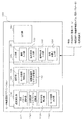
- FIG. 2 is a software block diagram schematically showing the processing configuration of the device selection application executed by the PC 1.
- the device selection application 100 performs a process of selecting a motor device suitable for a command condition and a mechanism condition (to be described later) of the multi-axis drive system for a motor apparatus provided in the multi-axis drive system to be designed by the user.
- the motor device is a general term for a motor, a motor control device, and peripheral devices related to motor control.
- the device selection application 100 corresponds to a device selection program described in each claim, and a functional part that executes the program in the configuration of the PC 1 corresponds to a device selection device described in each claim.
- the device selection application 100 includes a selection calculation unit 110, a storage unit 120, an input unit 130, and an output unit 140.
- the input unit 130 includes an axis number input unit 131, a command condition input unit 132, a mechanism condition input unit 133, and a load arithmetic expression input unit 134.
- the number-of-axis input unit 131 has a function of inputting the number of operation axes of the multi-axis drive system to be designed, that is, the number of motors required for driving the multi-axis drive system (hereinafter, the motor is appropriately referred to as an operation axis). ).
- the command condition input unit 132 has a function of inputting, as a command condition, a speed pattern that is assumed to be output to the control target of each motion axis in the multi-axis drive system.
- the mechanism condition input unit 133 is a function for inputting, as a mechanism condition, a driven mechanism model that defines the mechanical contents of the driven mechanism driven by each operating axis in the multi-axis driving system and its detailed design parameters.
- the load calculation formula input unit 134 has a function of inputting a load calculation formula used when calculating a load pattern representing a mode in which the load to be controlled fluctuates depending on the operation of another operation axis for each operation axis.
- the load pattern and the load calculation formula will be described in detail later with reference to FIG.
- the storage unit 120 includes a motor device characteristic database 121 (abbreviated as DB in the drawing) and a driven mechanism model storage unit 122.
- the motor device characteristic database 121 stores names of various motor devices and their respective specification characteristics in association with each other.
- the name of the motor device may be an individual model number or series name.
- the driven mechanism model storage unit 122 stores, for each of all types that can be normally used for the driven mechanism, mathematical formula calculation formulas and the like used when calculating the necessary driving force.
- the selection calculation unit 110 includes a load pattern calculation unit 111, a necessary drive torque pattern calculation unit 112, a required characteristic calculation unit 113, and a motor device selection unit 114.
- the load pattern calculation unit 111 represents the fluctuation of the load to be controlled on the predetermined operation axis based on the command condition input by the command condition input unit 132 and the load calculation formula input by the load calculation formula input unit 134. It has a function to calculate a load pattern.
- the necessary drive torque pattern calculation unit 112 refers to the driven mechanism model storage unit 122 while the mechanism condition input by the mechanism condition input unit 133, the command condition input by the command condition input unit 132, and the load Based on the load pattern calculated by the pattern calculation unit 111, it has a function of calculating a required driving torque pattern required for each operation axis in order to drive the entire driven mechanism.
- the required characteristic calculation unit 113 has a function of calculating the required characteristic required for the motor device of the operation axis based on the required drive torque pattern calculated by the required drive torque pattern calculation unit 112.
- the motor apparatus selection unit 114 selects and acquires a motor apparatus having a specification characteristic that meets and satisfies the required characteristic from the motor apparatus characteristic database 121.
- Has the function of The required characteristic calculation unit 113 and the motor device selection unit 114 correspond to the device selection unit described in each claim. The load pattern, required drive torque pattern, and required characteristics will be described in detail later.
- the output unit 140 has a function to output the screen for performing each input operation of the input unit 130, the name of the motor device selected by the motor device selection unit 114, and the like to a display device such as a display to show to the user.
- a display device such as a display to show to the user.
- the display corresponds to a display unit described in each claim.
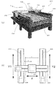
- FIG. 3 shows an example of a multi-axis drive system that is a target for selecting a motor device by the motor device selection device (device selection application 100) of the present embodiment.
- the illustrated multi-axis drive system is an XY table 200 using a so-called gantry mechanism.
- the XY table 200 includes a horizontal base 201 having a substantially rectangular parallelepiped shape, and Y-axis movable tables 202 and 203 are long on both long sides.
- Two Y-axis table moving mechanisms 204 and 205 that are movable along the side direction (Y direction) are provided.
- a movable beam 206 is bridged between the two Y-axis movable tables 202 and 203 in an arrangement parallel to the short side direction (X direction), and an X-axis movable table 207 is placed on the movable beam 206 in the short side direction.
- An X-axis table moving mechanism 208 that can be moved along is provided.
- the two Y-axis table moving mechanisms 204 and 205 and the X-axis table moving mechanism 208 are each provided with a driven mechanism including a horizontal ball screw mechanism driven by a rotary servo motor.
- the moving direction of one Y-axis movable table 202 is the Y1 axis direction (left side in the figure)
- the moving direction of the other Y-axis movable table 203 is the Y2 axis direction (see FIG. 3B).
- the movement direction of the X-axis movable table 207 is the X-axis direction.
- the multi-axis control system of the XY table 200 configured as described above is a device fixed on the X-axis movable table 207 by operating these three table moving mechanisms 204, 205, and 208 (FIG. 3 above). It is possible to control the XY coordinate movement on the horizontal plane (see the broken line portion in the middle).
- the X-axis table moving mechanism 208 corresponds to the X-axis driven mechanism described in each claim
- the Y1-axis table moving mechanism 204 corresponding to the Y1 axis corresponds to the Y1-axis moving mechanism described in each claim.
- the Y2-axis table moving mechanism 205 corresponding to the Y2-axis corresponds to the Y2-axis moving mechanism described in each claim.
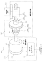
- each table moving mechanism is shown in FIG. Note that the configurations of the table moving mechanisms 204, 205, and 208 in the axial directions of the Y1, Y2, and X axes are basically the same as those shown in the drawing although there are differences in detailed design parameters. Is equivalent to The table moving mechanism 400 of the example shown in the figure is roughly composed of a motor driving mechanism 410, a driven mechanism 420, and a controlled object 430.
- the motor drive mechanism 410 includes a servo motor 411, an encoder 412, and a servo controller 413.
- the servo motor 411 is a rotary motor, and rotates its output shaft 411a in accordance with the drive power supplied from the servo controller 413.
- the encoder 412 is composed of, for example, an optical rotation number detector, and detects the rotation position and rotation angular velocity of the output shaft 411a of the servo motor with sufficient accuracy.
- the servo controller 413 controls drive power supplied to the servo motor 411 based on a drive control command input from a host controller (not shown) while referring to detection information from the encoder 412.
- the servo controller 413 corresponds to the motor control device described in each claim.
- the driven mechanism 420 in the illustrated example includes a coupling 421, a speed reducer 422, a coupling 423, and a horizontal ball screw mechanism 424, which are sequentially connected from the output shaft 411a of the servo motor.
- the reduction gear 422, which is one of the power transmission elements, is a gear-type reduction gear element in which two reduction gears of a main driving gear 422a and a driven gear 422b having different numbers of teeth are engaged.
- the horizontal ball screw mechanism 424 penetrates and screws the horizontally arranged ball screw 424a into the movable table 424b, and rotates the ball screw 424a in the forward and reverse directions, thereby moving the movable table 424b in the movement direction corresponding to the rotation direction.
- An actuator mechanism that moves along a direction.
- the two couplings 421 and 423 rotate by connecting the main driving gear 422a and the driven gear 422b of the speed reducer 422 to the output shaft 411a of the servo motor 411 and the ball screw 424a of the horizontal ball screw mechanism 424, respectively.
- It is a power transmission element that transmits driving force.
- the controlled object 430 is an object that is fixed to the output unit of the driven mechanism 420, that is, the movable table 424b in this example and is linearly moved.
- the total of the movable beam 206 and the X-axis table moving mechanism 208 is shared by the Y1-axis and the Y2-axis, respectively.
- Control object 430 In the case of the X-axis table moving mechanism 208, a device to be installed on the X-axis movable table 207 (refer to the broken line portion in FIG. 3A) is the control target 430.
- the multi-axis drive system including the motor drive mechanism 410 and the driven mechanism 420 described above is not actually manufactured but may be a virtual one at the design stage.
- the driven mechanism 420 has a structure in which all the power transmission elements are connected in series from the output shaft 411a of the servo motor in a line as described above.
- a method of selecting a servo motor and a servo controller having characteristics suitable for driving the table moving mechanisms 204, 205, and 208 having the above-described configuration in the device selection application 100 of the present embodiment will be described.
- the selection of the encoder 412 constituting the motor drive mechanism 410 will be described later.
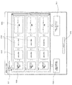
- FIG. 5 shows an example of an operation screen for inputting and setting such conditions and arithmetic expressions.
- the operation screen shown in FIG. 5 is displayed on a display device such as a display by the function of the output unit 140 when the device selection application 100 is activated on the PC 1.
- the operation screen includes an axis number input operation unit 501, a speed diagram setting operation unit 502, a mechanism setting operation unit 503, a load pattern setting operation unit 504, a single axis selection operation unit 505, and a multi-axis speed line.
- a diagram setting operation unit 506, a multi-axis selection operation unit 507, and a setting completion operation unit 508 are provided, and the user can select and operate the operation units in a predetermined order (or any order).
- the user can set and input the number of operating axes provided in the multi-axis drive system to be designed, that is, the number of motors, using the axis number input operation unit 501.
- the axis number input operation unit 501 is an operation unit that functions by the axis number input unit 131 described above.
- the velocity diagram setting operation unit 502, the mechanism setting operation unit 503, the load pattern setting operation unit 504, and the single axis selection operation unit 505 are arranged in this order from the left side in the drawing.
- the columns of the operation units displayed are arranged in the vertical direction according to the number of set axes. In the example shown in the figure, since three axes are set, they are displayed in three columns corresponding to each operation axis.
- the speed diagram setting operation unit 502 is an operation unit that functions by the command condition input unit 132, and an operation amount assumed to be output by the output unit of the driven mechanism of each operation axis, that is, the control target is, for example, Set as a command condition using a time-series change pattern.
- this operation amount is commanded by the movement speed of the control target, and specifically, it is set by a speed pattern (speed diagram) expressed in a time series as shown in FIG.
- the speed pattern may be set by the user in an arbitrary pattern (arbitrary acceleration / deceleration speed, steady speed, time length), or may be set by selecting a plurality of patterns prepared in advance.
- a single axis speed pattern setting operation screen corresponds to the first display section described in each claim.
- the multi-axis velocity diagram setting operation unit 506 can set the speed pattern to be controlled for all the operation axes on the same time axis as shown in FIG.
- the operation timing of each operation axis can be set.
- a multi-axis speed pattern setting operation screen corresponds to the fifth display section described in each claim.
- the command conditions expressed by these speed patterns may be set to contents that are more fluctuating than the actually assumed usage in order to verify the controllability of the entire multi-axis drive system, or actually assumed.
- the content may be set according to the usage pattern.
- the mechanism setting operation unit 503 is an operation unit that functions by the mechanism condition input unit 133 described above, and sets the overall mechanical type and the design parameters of each component as a mechanism condition for the driven mechanism of each operation axis. .
- a number of types of driven mechanism models stored in the driven mechanism model storage unit 122 are listed as shown in FIG. 8 (see the lower left in the figure), and the user selects them among them.
- the necessary design parameters are input to the driven mechanism model (see the upper right in the figure).
- the mechanism condition setting operation screen corresponds to the second display section described in each claim.
- the user may set an arbitrary driven mechanism model by selecting and combining a plurality of types of power transmission elements.
- the device selection application 100 can grasp the mechanical contents of the driven mechanism of each axis.
- the input load mass to be controlled is also set. However, it is possible to operate an option to be selected when the load mass fluctuates due to the operation of other operation axes.
- the load to be controlled by the X-axis table moving mechanism 208 is not affected by the operation of the other operation axes, and thus remains unchanged.
- the load mass can be input and set as it is.
- the load pattern setting operation unit 504 corresponding to the X axis (“first axis” in the figure) does not function on the operation screen of FIG. Is displayed).
- the motor device for the X-axis can be selected when the command condition and the mechanism condition are input and set.
- a necessary drive torque pattern and required characteristics must be calculated. That is, in order to move to the controlled object of the X-axis table moving mechanism 208 with the speed pattern set as the command condition, all the power transmission elements constituting the driven mechanism and the load to be controlled are necessary for driving.
- the required drive torque is individually analyzed based on the mechanism conditions.
- torque calculation tilt calculation
- the required drive torque for each control object and power transmission element is accumulated to obtain a time series pattern of the required drive torque required for the servo motor, and the servo motor is requested based on the required drive torque pattern. Calculate the required characteristics.
- the required driving torque of the X-axis servo motor to realize this Is a time-series change pattern as shown in FIG.
- the necessary drive torque pattern shown in FIG. 9B indicates that a positive torque with respect to the rotation direction is required in the acceleration period, and a negative torque with respect to the rotation direction is required in the deceleration period (respectively, FIG. 9B). (See the shaded display inside). In the constant speed period, a constant low torque that compensates for the power loss caused by friction or the like may be used. Further, the required drive torque pattern calculation unit 112 in FIG. 2 functions to calculate the required drive torque pattern.
- the required characteristic calculation unit 113 in FIG. 2 Based on the required drive torque pattern thus analyzed, the required characteristic calculation unit 113 in FIG. 2 performs the maximum current, power consumption, and regenerative energy required for the X-axis motor device in accordance with the command conditions. Then, characteristics such as necessary regenerative resistance, that is, required characteristics are calculated.
- FIG. 10 shows a display example of the actual waveform and required characteristics of such a required drive torque pattern.
- the motor device selection unit 114 in FIG. 2 acquires the names of the motor devices (servo motors, servo controllers) satisfying the required characteristics to the minimum necessary from the motor device characteristics database 121, and the selection in FIG. By displaying on the name display unit 510, the user can select an appropriate motor device on the X axis. In addition, said selection name display part is corresponded to the 3rd display part of each claim description.
- the load to be controlled by the respective table moving mechanisms 204 and 205 affects the operation of the X1 axis.
- the load mass of the control target of the Y1 axis increases and the load mass of the control target of the Y2 axis decreases.
- the load mass of the control target of the Y2 axis increases and the load mass of the control target of the Y1 axis decreases. If this point is not taken into consideration, the Y1-axis and Y2-axis motor devices cannot be appropriately selected.
- the load masses that are controlled by the Y1-axis table moving mechanism 204 and the Y2-axis table moving mechanism 205 are not limited to the shared load masses My1 and My2 obtained by the above equations (1) and (2).
- each load mass between interlocking multiple axes is individually obtained by an arithmetic expression using the operation amount (acceleration, speed, displacement, inclination, etc.) of other operation axes.
- Such a relational calculation formula is created as a load calculation formula if the user is a designer who knows the mechanical configuration of the multi-axis drive system, and the load pattern setting operation unit 504 shown in FIG. Load calculation formula can be input.
- the load mass to be controlled of the shaft can be replaced with an increase or decrease in apparent fixed mass, and can be calculated individually.
- the load calculation expression to be controlled is a linear expression using the movement position x of the X-axis movable table 207 as a variable. Therefore, it is necessary to obtain the movement position x.
- the device selection application 100 internally integrates the speed pattern input as a command condition for the X axis, so that the movement representing the change in the movement position x in time series is shown. It can be determined as a quantity pattern.
- This movement amount pattern corresponds to the movement amount variation described in each claim. Then, with respect to this movement amount pattern, the load pattern calculation unit 111 in FIG.
- An operation process is performed.
- a second stage operation process is performed in which both the Y1 axis and the Y2 axis are moved to the farthest side.
- the fourth stage operation process is performed in which both the Y1 axis and the Y2 axis are moved back to the nearest side, and the process ends.
- a speed pattern as shown in the figure is input as a command condition for performing the above four-step operation process.
- the device selection application 100 internally calculates and calculates an X-axis movement amount pattern (not shown), and based on the X-axis movement amount pattern, the load pattern calculation unit in FIG. 111 calculates the load pattern shown in FIG. 13 using the load calculation formula of each operation axis. Further, based on these load patterns, the required drive torque pattern calculation unit 112 in FIG. 2 calculates the required drive torque pattern shown in FIG. 14 in consideration of the mechanism conditions.
- the required characteristic calculation unit 113 in FIG. 2 calculates the required characteristics based on the required drive torque pattern of each motion axis analyzed in this way. Then, the motor device selection unit 114 in FIG. 2 selects a motor device that satisfies the required characteristics from the motor device characteristic database 121 and displays their names.
- FIG. 15 shows a schematic summary of the above selection process steps. That is, the necessary drive torque pattern is calculated based on the speed pattern input as the command condition, the load pattern obtained from the movement amount pattern of each operation axis calculated internally and the input load calculation formula. This calculation takes into account the input mechanism conditions. A required characteristic is calculated based on the calculated required drive torque pattern, and the selection process is completed by selecting a motor device that satisfies the required characteristic to the minimum necessary. In the present embodiment, such motor device selection processing can be individually performed for each operation axis in the multi-axis drive system.
- the name of the peripheral device corresponding to the motor device characteristic database 121 and the required characteristic are stored in association with each other, and the above required characteristic is calculated. Further, it is only necessary to select from the motor device characteristic database 121 that the required characteristics of the peripheral device are calculated and matched. Further, although not particularly illustrated, when there are a plurality of motor devices that meet the required characteristics, a list of all the names may be displayed and the user may select them.
- FIG. 16 is an example of a flowchart showing the control contents executed by the CPU of the PC 1 in order to realize the motor device selection process according to the present embodiment described above. This flow starts when the device selection application 100 is activated.
- step S5 the number-of-axis input unit 131 shown in FIG. 2 performs an input operation from the user via the number-of-axis input operation unit 501 in FIG.
- the number of axes of the XY table 200) is set.
- step S10 the command condition input unit 132 shown in FIG. 2 performs a speed pattern to be controlled for each motion axis by an input operation from the user via the speed diagram setting operation unit 502 in FIG. (See FIGS. 6 and 7 for the actual setting operation screen).
- step S15 the mechanism condition input unit 133 shown in FIG. 2 sets the mechanism conditions for each motion axis by an input operation from the user via the mechanism setting operation unit 503 in FIG. (See FIG. 8 for the setting operation screen).
- step S20 the load calculation formula input unit 134 shown in FIG. 2 sets a load calculation formula for each motion axis by an input operation from the user via the load pattern setting operation unit 504 in FIG. To do.
- step S25 the load pattern calculation unit 111 shown in FIG. 2 calculates the load pattern of each motion axis by the processing described with reference to FIGS.
- step S30 the required drive torque pattern calculation unit 112 shown in FIG. 2 calculates the required drive torque pattern for each operating axis by the processing described in FIG.
- step S35 the required characteristic calculation unit 113 shown in FIG. 2 calculates the required characteristic of the corresponding motor device from the required drive torque pattern of each operation axis.
- step S40 the motor device selection unit 114 shown in FIG. 2 refers to the motor device characteristic database 121 to select a motor device that matches the required characteristics of each operation axis.
- step S45 the output unit 140 shown in FIG. 2 displays the name of the motor device of each operation axis selected in step S40. Then, this flow ends.
- step S10 the setting performed by the procedure of said step S10, step S15, and step S20, respectively.
- the procedure of step S10 in the flow of FIG. 16 corresponds to the first display control procedure and the first display procedure described in each claim
- the procedure of step S15 is the second display control procedure and the first display procedure described in each claim.
- 5 display control procedure and second display procedure the procedure of step S25 corresponds to the load pattern calculation procedure, load pattern calculation control procedure and load pattern calculation procedure described in each claim
- the procedure of step S30 is each claim. It corresponds to the required drive torque pattern calculation control procedure and the required drive torque pattern calculation procedure described
- the procedure of step S45 is the third display control procedure, device selection control procedure, third display procedure, and device selection procedure described in each claim. Equivalent to.
- peripherals including servo motors and motor control devices that are optimal for each driven mechanism while taking into account fluctuations in the load mass borne by each driven mechanism.
- Equipment can be selected.
- a user sets a speed pattern and a mechanism condition to be controlled for each of a plurality of motion axes corresponding to a plurality of driven mechanisms.
- the user sets a load calculation formula for a necessary motion axis.
- the variation of the shared load mass that is shared and burdened when operating in conjunction with other operating axes is obtained from the load calculation formula, and based on that The variation of the load mass of the control target of the motion axis alone is calculated (the shared load mass may be constant).
- the required drive torque pattern and the required characteristics of the operation shaft are calculated.
- at least one servo motor and at least one servo controller that match the required characteristics are selected from a plurality of servo motors and servo controllers prepared in advance, and their names are Listed.
- the user can select the appropriate servo motor and servo controller from among the listed servo motors and servo controllers while taking into account the variation in mass load borne by each driven mechanism in the multi-axis drive system to be designed.
- Servo motors and servo controllers with specifications can be easily selected.
- the required drive torque pattern of the operation axis is calculated using the load pattern representing the variation of the load mass to be controlled calculated by the load pattern calculation unit 111 and the set speed pattern.
- the required characteristics are calculated.
- the movement of the load mass actually generated by the operation of the controlled object performed by a certain driven mechanism is converted into the increase or decrease of the apparent fixed mass of the controlled object borne by another driven mechanism.
- the calculation is performed by replacing the phenomenon in which the load mass having a constant value moves with the phenomenon in which the value of the virtual load mass located at the fixed point increases or decreases.
- the load pattern calculation part 111 can obtain
- the load pattern calculation unit 111 adds a predetermined load variable coefficient (inertia moment load) to the movement amount pattern of the X axis obtained by integrating the speed pattern set corresponding to the X axis. Is converted to the load patterns of the Y1 axis and Y2 axis by adding the initial weight burden of the load mass to be controlled borne by the driven mechanism of the X axis. Thereby, the load pattern calculation part 111 can obtain
- the servo controller is also selected in one-to-one correspondence with the servo motor. That is, the case where a single-axis servo controller is selected has been described.
- the present invention is not limited to this, and can also be used to select a multi-axis servo controller that collectively controls a plurality of servo motors.
- FIG. 17 displayed by the operation of the multi-axis selection operation unit 507, required characteristics (maximum current, consumption) that can simultaneously realize the necessary drive torque patterns of the respective operation axes on the same time axis.
- Multi-axis servo controller and multi-axis common converter may be selected.
- FIG. 17 displayed by the operation of the multi-axis selection operation unit 507
- required characteristics maximum current, consumption
- a single-axis servo controller that is suitable for each operating axis can be selected, and a multi-axis servo controller or multi-axis common converter with the characteristics of these single-axis servo controllers can be selected.
- the screen for selecting and displaying at least one recommended servo controller corresponding to all of the plurality of driven mechanisms in this way corresponds to the fourth display section described in each claim, and displays the display screen.
- the control procedure corresponds to the fourth display control procedure described in each claim.
- the setting shown in FIG. 7 is performed by displaying a plurality of speed patterns set on the setting screen shown in FIG. 6 side by side on the same time axis. Display the screen.
- the setting screen shown in FIG. 7 corresponds to the fifth display section described in each claim.
- the X-axis table moving mechanism 208 that performs linear movement along the X-axis as the operation axis with respect to the load mass, and one end of the X-axis table moving mechanism 208 are provided.
- a Y1 axis table moving mechanism 204 that supports and moves linearly along the Y1 axis as an operation axis with respect to the one end portion, and supports the other end portion of the X axis table movement mechanism 208 and supports the other end portion as an operation axis.
- a servo motor is selected in a multi-axis drive system of an XY table 200 having a Y2 axis table moving mechanism 205 that performs linear movement along the Y2 axis parallel to the Y1 axis.
- the X-axis table moving mechanism 208 that moves the control target along the X-axis, the three axes that linearly move in the Y1-axis and Y2-axis directions by the Y1-axis table moving mechanism 204 and the Y2-axis table moving mechanism 205.
- Servo motors and servo controllers having appropriate specifications with no excess or deficiency for the drive system can be easily selected.
- command condition is not limited to the input of the speed pattern, but may be input with another operation amount such as a movement position pattern (movement amount pattern) to be controlled.
- the input of the command condition, the mechanism condition, and the load calculation formula may be input by the device selection application 100A and exported to the external analysis application. It may be input directly to an external analysis application. Then, the device selection application 100A of the present modification imports the combination of the load pattern and the speed pattern of each operation axis calculated from the external analysis application, and calculates the necessary drive torque pattern of each operation axis based on them. Corresponding required characteristics may be calculated from the necessary drive torque patterns of the respective operation axes, and the names of the motor devices that are suitable for each may be selected.
- the load calculation formula for example, calculation formula by Newton Euler method, Lagrangian equation of motion, etc.
- the processing block that acquires the combination of the load pattern and the speed pattern for each driven mechanism from the external analysis application corresponds to the combination acquisition unit and combination acquisition procedure described in each claim, and inputs the mechanism conditions of each motion axis
- the operation screen to be displayed corresponds to the sixth display section described in each claim
- the control procedure for displaying this operation screen corresponds to the sixth display control procedure and the fourth display procedure described in each claim.
- the screen for displaying the name of the motor device selected based on the combination of the speed patterns corresponds to the seventh display section described in each claim
- the control procedure for displaying this display screen is the seventh display control procedure described in each claim. This corresponds to the fifth display procedure.
- the combination of the speed patterns of the load patterns of the operation axes in the multi-axis drive system having a complicated configuration can be acquired from the external analysis application.
- the application 100A itself can easily select a servo motor and a servo controller having appropriate specifications without excess or deficiency of each operation axis in the same manner as the above embodiment with a simple configuration.
- the load pattern may be imported from the external analysis application, and the velocity pattern of the same motion axis combination may be input and acquired by the device selection application 100A.
- the device selection application 100, 100A has been described as a stand-alone application that is activated by a program stored in an internal storage device such as the HDD of the PC 1. It is also possible to adopt a form of a net application (WEB application) that is activated when connected to an external server.
- WEB application net application
Landscapes
- Engineering & Computer Science (AREA)
- Power Engineering (AREA)
- General Physics & Mathematics (AREA)
- Manufacturing & Machinery (AREA)
- Physics & Mathematics (AREA)
- Automation & Control Theory (AREA)
- Computer Hardware Design (AREA)
- Microelectronics & Electronic Packaging (AREA)
- Human Computer Interaction (AREA)
- Control Of Multiple Motors (AREA)
- Control Of Electric Motors In General (AREA)
- Quality & Reliability (AREA)
- General Engineering & Computer Science (AREA)
Description
開示の実施形態は、機器選定装置、及び機器選定処理プログラム、並びに機器選定処理方法に関する。
特許文献1には、入力装置を介して被駆動機構(例えばボールねじ機構)が選択され、さらに機械諸元が入力され、さらに負荷の運動パターンが入力されると、対応するサーボモータの要求仕様が求められ、その条件に適合したサーボモータが一覧される、サーボモータ選定処理装置が記載されている。
しかしながら、特許文献1に記載のものでは、複数の被駆動機構を備えた多軸駆動システムにおけるサーボモータの選定処理については、特に配慮されていなかった。
本発明はこのような問題点に鑑みてなされたものであり、複数の被駆動機構を備えた多軸駆動システムのサーボモータ及びモータ制御装置の選定処理を容易に行える、機器選定処理装置、及び機器選定処理プログラム、並びに機器選定処理方法を提供することを目的とする。
上記課題を解決するため、本発明の一の観点によれば、サーボモータの駆動力に基づき、複数の被駆動機構が互いに連動して動作する多軸駆動システムにおける、前記サーボモータ及びモータ制御装置を含む周辺機器の選定を行う機器選定装置であって、各動作軸ごとに、予め用意された複数の速度パターンから1つの速度パターンの選択を促す表示を行う、第1表示部と、各動作軸ごとに、予め用意された前記複数の被駆動機構から1つの前記被駆動機構の選択を促す表示を行う、第2表示部と、各動作軸ごとに、前記第2表示部における表示に対応した前記被駆動機構の選択結果に応じ、当該選択された1つの被駆動機構が他の被駆動機構と連動して動作するときに当該1つの被駆動機構が負担する負荷質量の変動、及び、当該1つの被駆動機構に関わる前記速度パターンの選択結果、に適合する少なくとも1つのサーボモータ及び少なくとも1つのモータ制御装置を、予め用意された複数のサーボモータ及び複数のモータ制御装置の中から抽出してそれらの名称を一覧表示し、その一覧表示の中からの選択を促す表示を行う、第3表示部と、を有する機器選定装置が適用される。
上記課題を解決するため、本発明の一の観点によれば、サーボモータの駆動力に基づき、複数の被駆動機構が互いに連動して動作する多軸駆動システムにおける、前記サーボモータ及びモータ制御装置を含む周辺機器の選定を行う機器選定装置であって、前記多軸駆動システムが所定の複数の動作態様を行うときの各動作態様ごとに予め求められている、1つの被駆動機構が他の被駆動機構に連動して動作するときに負担する負荷質量の変動と当該1つの被駆動機構に関わる速度パターンとの組合せを、各被駆動機構ごとに取得する組み合わせ取得部と、各動作軸ごとに、予め用意された前記複数の被駆動機構から1つの前記被駆動機構の選択を促す表示を行う、第6表示部と、各動作軸ごとに、前記第6表示部における表示に対応した前記被駆動機構の選択結果、及び、当該選択された1つの被駆動機構に関する前記組み合わせ取得部での取得結果、に適合する少なくとも1つのサーボモータ及び少なくとも1つのモータ制御装置を、予め用意された複数のサーボモータ及び複数のモータ制御装置の中から抽出して一覧表示し、その一覧表示の中からの選択を促す表示を行う、第7表示部と、を有する機器選定装置が適用される。
上記課題を解決するため、本発明の一の観点によれば、それぞれ個別のサーボモータにより駆動される複数の被駆動機構が互いに連動して動作する多軸駆動システムに対し、その設計上で前記サーボモータ及びモータ制御装置を含む周辺機器の選定を行う機器選定装置であって、前記複数の被駆動機構のうち選択された1つの被駆動機構が動作させる対象の負荷が、他の被駆動機構の動作に基づいて変動する態様を表す負荷パターンを演算する負荷パターン演算部と、前記1つの被駆動機構がその動作で前記負荷パターンで示される負荷を動作させるために、前記1つの被駆動機構を駆動する前記サーボモータに必要とされる必要駆動トルクパターンを演算する必要駆動トルクパターン演算部と、前記必要駆動トルクパターンに基づいて、前記1つの被駆動機構の駆動に適合するサーボモータ及びモータ制御装置を選定する機器選定部と、を有する機器選定装置が適用される。
上記課題を解決するため、本発明の一の観点によれば、サーボモータの駆動力に基づき、複数の被駆動機構が互いに連動して動作する多軸駆動システムにおける、前記サーボモータ及びモータ制御装置を含む周辺機器の選定を行うとともに、所定の演算を行う演算部及び所定の表示を行う表示部を備えた、機器選定装置の前記演算部に対し、各動作軸ごとに、予め用意された複数の速度パターンから1つの速度パターンの選択を促す表示を行うための制御信号を、前記表示部に出力する第1表示制御手順と、各動作軸ごとに、予め用意された前記複数の被駆動機構から1つの前記被駆動機構の選択を促す表示を行うための制御信号を、前記表示部に出力する第2表示制御手順と、各動作軸ごとに、前記第2表示制御手順の前記表示部の表示に対応した前記被駆動機構の選択結果に応じ、当該選択された1つの被駆動機構が他の被駆動機構と連動して動作するときに当該1つの被駆動機構が負担する負荷質量の変動、及び、当該1つの被駆動機構に関わる前記速度パターンの選択結果、に適合する少なくとも1つのサーボモータ及び少なくとも1つのモータ制御装置を、予め用意された複数のサーボモータ及び複数のモータ制御装置の中から抽出してそれらの名称を一覧表示し、その一覧表示の中からの選択を促す表示を行うための制御信号を、前記表示部に出力する第3表示制御手順と、を実行させる機器選定処理プログラムが適用される。
上記課題を解決するため、本発明の一の観点によれば、サーボモータの駆動力に基づき、複数の被駆動機構が互いに連動して動作する多軸駆動システムにおける、前記サーボモータ及びモータ制御装置を含む周辺機器の選定を行うとともに、所定の演算を行う演算部及び所定の表示を行う表示部を備えた、機器選定装置の前記演算部に対し、前記多軸駆動システムが所定の複数の動作態様を行うときの各動作態様ごとに予め求められている、1つの被駆動機構が他の被駆動機構に連動して動作するときに負担する負荷質量の変動と当該1つの被駆動機構に関わる速度パターンとの組合せを、各被駆動機構ごとに取得する組み合わせ取得手順と、各動作軸ごとに、予め用意された前記複数の被駆動機構から1つの前記被駆動機構の選択を促す表示を行うための制御信号を、前記表示部に出力する第6表示制御手順と、各動作軸ごとに、前記第6表示制御手順の前記表示部の表示に対応した前記被駆動機構の選択結果、及び、当該選択された1つの被駆動機構に関する前記組み合わせ手順での取得結果、に適合する少なくとも1つのサーボモータ及び少なくとも1つのモータ制御装置を、予め用意された複数のサーボモータ及び複数のモータ制御装置の中から抽出してそれらの名称を一覧表示し、その一覧表示の中からの選択を促す表示を行うための制御信号を、前記表示部に出力する第7表示制御手順と、を有する機器選定処理プログラムが適用される。
上記課題を解決するため、本発明の一の観点によれば、それぞれ個別のサーボモータにより駆動される複数の被駆動機構が互いに連動して動作する多軸駆動システムに対し、その設計上で前記サーボモータ及びモータ制御装置を含む周辺機器の選定を行う機器選定装置の演算部に対し、前記複数の被駆動機構のうち選択された1つの被駆動機構が動作させる対象の負荷が、他の被駆動機構の動作に基づいて変動する態様を表す負荷パターンを演算する負荷パターン演算制御手順と、前記1つの被駆動機構がその動作で前記負荷パターンで示される負荷を動作させるために、前記1つの被駆動機構を駆動する前記サーボモータに必要とされる必要駆動トルクパターンを演算する必要駆動トルクパターン演算制御手順と、前記必要駆動トルクパターンに基づいて、前記1つの被駆動機構の駆動に適合するサーボモータ及びモータ制御装置を選定する機器選定制御手順と、を実行させる機器選定プログラムが適用される。
上記課題を解決するため、本発明の一の観点によれば、サーボモータの駆動力に基づき、複数の被駆動機構が互いに連動して動作する多軸駆動システムにおける、前記サーボモータ及びモータ制御装置を含む周辺機器の選定を行う機器選定装置が実行する機器選定処理方法であって、各動作軸ごとに、予め用意された複数の速度パターンから1つの速度パターンの選択を促す表示を行う第1表示手順と、各動作軸ごとに、予め用意された前記複数の被駆動機構から1つの前記被駆動機構の選択を促す表示を行う第2表示手順と、各動作軸ごとに、前記第2表示手順の表示に対応した前記被駆動機構の選択結果に応じ、当該選択された1つの被駆動機構が他の被駆動機構と連動して動作するときに当該1つの被駆動機構が負担する負荷質量の変動、及び、当該1つの被駆動機構に関わる前記速度パターンの選択結果、に適合する少なくとも1つのサーボモータ及び少なくとも1つのモータ制御装置を、予め用意された複数のサーボモータ及び複数のモータ制御装置の中から抽出してそれらの名称を一覧表示し、その一覧表示の中からの選択を促す表示を行う、第3表示手順と、を有する機器選定処理方法が適用される。
上記課題を解決するため、本発明の一の観点によれば、サーボモータの駆動力に基づき、複数の被駆動機構が互いに連動して動作する多軸駆動システムにおける、前記サーボモータ及びモータ制御装置を含む周辺機器の選定を行う機器選定装置が実行する機器選定処理方法であって、前記多軸駆動システムが所定の複数の動作態様を行うときの各動作態様ごとに予め求められている、1つの被駆動機構が他の被駆動機構に連動して動作するときに負担する負荷質量の変動と当該1つの被駆動機構に関わる速度パターンとの組合せを、各被駆動機構ごとに取得する組み合わせ取得手順と、各動作軸ごとに、予め用意された前記複数の被駆動機構から1つの前記被駆動機構の選択を促す表示を行う、第4表示手順と、各動作軸ごとに、前記第4表示手順の表示に対応した前記被駆動機構の選択結果、及び、当該選択された1つの被駆動機構に関する前記組み合わせ手順での取得結果、に適合する少なくとも1つのサーボモータ及び少なくとも1つのモータ制御装置を、予め用意された複数のサーボモータ及び複数のモータ制御装置の中から抽出してそれらの名称を一覧表示し、その一覧表示の中からの選択を促す表示を行う、第5表示手順と、を有する機器選定処理方法が適用される。
上記課題を解決するため、本発明の一の観点によれば、それぞれ個別のサーボモータにより駆動される複数の被駆動機構が互いに連動して動作する多軸駆動システムに対し、その設計上で前記サーボモータ及びモータ制御装置を含む周辺機器の選定を行う機器選定装置が実行する機器選定処理方法であって、前記複数の被駆動機構のうち選択された1つの被駆動機構が動作させる対象の負荷が、他の被駆動機構の動作に基づいて変動する態様を表す負荷パターンを演算する負荷パターン演算手順と、前記1つの被駆動機構がその動作で前記負荷パターンで示される負荷を動作させるために、前記1つの被駆動機構を駆動する前記サーボモータに必要とされる必要駆動トルクパターンを演算する必要駆動トルクパターン演算手順と、前記必要駆動トルクパターンに基づいて、前記1つの被駆動機構の駆動に適合するサーボモータ及びモータ制御装置を選定する機器選定手順と、を有する機器選定処理方法が適用される。
本発明によれば、操作者は、自らの所望する構成の多軸駆動システムにおいて各被駆動機構が負担する質量負荷の変動を加味しつつ、一覧表示されたサーボモータ及びモータ制御装置の名称の中から、過不足のない適正なスペックを備えたサーボモータ及びモータ制御装置を容易に選定することができる。
以下、一実施形態を図面を参照しつつ説明する。
図1は、一実施形態に係る機器選定装置の外観全体を表した図である。図示する例の機器選定装置は、一般的なパーソナルコンピュータ1(以下、PCと略記)で具現化されており、当該PC1で実行するソフトウェアアプリケーションによって機器選定処理を実現する。なお、特に図示しないが、当該PC1にはCPU、ROM、RAM、HDD、DVDドライブなどのリムーバブルメディアドライブ、キーボード、マウスなどのポインティングデバイス、ディスプレイ、ネットワークインターフェースなどの一般的なPCの構成を備えていればよく、その他の詳細なハードウェア構成については説明を省略する。
図2は、当該PC1が実行する機器選定アプリケーションの処理構成を模式的に表すソフトウェアブロック図である。この機器選定アプリケーション100は、ユーザが設計しようとする多軸駆動システムに備えられるモータ機器について、当該多軸駆動システムの後述する指令条件、機構条件に適合したモータ機器の選定処理を行う。なお、以下においてモータ機器とは、モータ、モータ制御装置、及びモータ制御に関係する周辺機器の総称をいう。また、上記機器選定アプリケーション100が各請求項記載の機器選定プログラムに相当し、上記PC1の構成のうち当該プログラムを実行する機能部分が各請求項記載の機器選定装置に相当する。
最初に本実施形態の機器選定アプリケーション100の処理構成について説明する。図2において、機器選定アプリケーション100は、選定演算部110と、記憶部120と、入力部130と、出力部140とを有している。
まず入力部130は、軸数入力部131と、指令条件入力部132と、機構条件入力部133と、負荷演算式入力部134とを有している。
軸数入力部131は、設計対象の多軸駆動システムの動作軸数、つまり当該多軸駆動システムの駆動に必要とされるモータの数を入力する機能を有する(以下、適宜モータを動作軸という)。
指令条件入力部132は、上記多軸駆動システム中の各動作軸の制御対象に出力させるよう想定した速度パターンを指令条件として入力する機能を有する。
機構条件入力部133は、上記多軸駆動システム中で各動作軸が駆動する被駆動機構について、その機構的な内容を規定する被駆動機構モデルとその詳細な設計パラメータを機構条件として入力する機能を有する。なお、上記の制御対象、指令条件、被駆動機構、及び機構条件については後述の図4で詳述する。
負荷演算式入力部134は、各動作軸ごとにその制御対象の負荷が、他動作軸の動作によって変動する態様を表す負荷パターンを演算する際に用いる負荷演算式を入力する機能を有する。なお、上記の負荷パターン及び負荷演算式については後述の図11で詳述する。
次に記憶部120は、モータ機器特性データベース121(図中ではDBと略記)と、被駆動機構モデル記憶部122とを有している。モータ機器特性データベース121は、各種モータ機器の名称とそれぞれの仕様特性を対応付けて記憶する。モータ機器の名称としては、個々の型番やシリーズ名称であってもよい。被駆動機構モデル記憶部122は、上記被駆動機構について通常使用し得る全ての種類ごとに、その必要駆動力を算出する際に用いる数理モデルの計算式等を記憶する。
次に選定演算部110は、負荷パターン演算部111と、必要駆動トルクパターン演算部112と、要求特性算出部113と、モータ機器選定部114とを有している。
負荷パターン演算部111は、上記指令条件入力部132で入力した指令条件と、上記負荷演算式入力部134で入力した負荷演算式とに基づいて、所定動作軸における制御対象の負荷の変動を表す負荷パターンを演算する機能を有する。
必要駆動トルクパターン演算部112は、上記被駆動機構モデル記憶部122を参照しつつ、上記機構条件入力部133で入力した機構条件と、上記指令条件入力部132で入力した指令条件と、上記負荷パターン演算部111で演算した負荷パターンに基づいて、上記被駆動機構の全体を駆動するために各動作軸に必要とされる必要駆動トルクパターンを演算する機能を有する。
要求特性算出部113は、上記必要駆動トルクパターン演算部112が演算した必要駆動トルクパターンに基づいて、当該動作軸のモータ機器に要求される要求特性を算出する機能を有する。
モータ機器選定部114は、上記要求特性算出部113が算出した要求特性に基づいて、当該要求特性を必要最小限に満たして適合する仕様特性のモータ機器を上記モータ機器特性データベース121から選定し取得する機能を有する。なお、上記の要求特性算出部113及びモータ機器選定部114が、各請求項記載の機器選定部に相当する。また、上記の負荷パターン、必要駆動トルクパターン、及び要求特性については後に詳述する。
次に出力部140は、上記入力部130の各入力操作を行う画面や、上記モータ機器選定部114で選定したモータ機器の名称などを例えばディスプレイなどの表示装置に出力してユーザに示す機能を有する。なお、上記のディスプレイが各請求項記載の表示部に相当する。
以下に、本実施形態によるモータ機器の選定手法について、具体的な多軸駆動システムの一例を挙げて説明する。
本実施形態のモータ機器選定装置(機器選定アプリケーション100)によりモータ機器の選定を行う対象の多軸駆動システムの一例を図3に示す。図示する例の多軸駆動システムは、いわゆるガントリ機構を利用したX-Yテーブル200である。図3(a)の外観斜視図に示すように、当該X-Yテーブル200は、略直方体形状の水平基台201を備え、この両側長辺部にはそれぞれY軸可動テーブル202、203を長辺方向(Y方向)に沿って移動可能な2つのY軸テーブル移動機構204、205を設けている。それら2つのY軸可動テーブル202、203の間で短辺方向(X方向)に平行な配置で可動梁206を掛け渡し、さらに当該可動梁206上にはX軸可動テーブル207を短辺方向に沿って移動可能なX軸テーブル移動機構208を設けている。
この例では、上記2つのY軸テーブル移動機構204、205及びX軸テーブル移動機構208が、それぞれ回転型サーボモータにより駆動される水平ボールねじ機構を備えた被駆動機構を備えている。また、図3(b)に示すように、一方のY軸可動テーブル202の移動方向をY1軸方向(図中の左側)とし、他方のY軸可動テーブル203の移動方向をY2軸方向(図中の右側)とし、X軸可動テーブル207の移動方向をX軸方向とする。以上のように構成したX-Yテーブル200の多軸制御システムは、これら3つのテーブル移動機構204、205、208を連携動作させることによって、X軸可動テーブル207上に固定した機器(上記図3中の破線部参照)の水平面上のX-Y座標移動を制御することができる。なお、上記のX軸テーブル移動機構208が各請求項記載のX軸被駆動機構に相当し、上記のY1軸に対応するY1軸テーブル移動機構204が各請求項記載のY1軸移動機構に相当し、上記のY2軸に対応するY2軸テーブル移動機構205が各請求項記載のY2軸移動機構に相当する。
各テーブル移動機構の詳細構成を図4に示す。なお、上記のY1、Y2軸、及びX軸の各軸方向のテーブル移動機構204、205、208のそれぞれの構成は、いずれも詳細な設計パラメータに差異があるものの、基本的には図示する構成と同等である。図示する例のテーブル移動機構400は、概略的にモータ駆動機構410と、被駆動機構420と、制御対象430とで構成される。
モータ駆動機構410は、サーボモータ411と、エンコーダ412と、サーボコントローラ413とを有している。サーボモータ411は、この例では回転型モータであり、サーボコントローラ413から供給される駆動電力に応じてその出力軸411aを回転駆動させる。エンコーダ412は、例えば光学式の回転数検出器などで構成され、上記サーボモータの出力軸411aの回転位置、回転角速度を十分な精度で検出する。サーボコントローラ413は、上記エンコーダ412からの検出情報を参照しつつ、特に図示しない上位制御装置から入力される駆動制御指令に基づいて上記サーボモータ411に供給する駆動電力を制御する。なお、このサーボコントローラ413が、各請求項記載のモータ制御装置に相当する。
また、図示する例の被駆動機構420は、カップリング421と、減速機422と、カップリング423と、水平ボールねじ機構424とを順に上記サーボモータの出力軸411aから連結して備えている。動力伝達要素の1つである減速機422は、歯数の異なる主動ギア422aと従動ギア422bの2つの減速ギアを噛み合わせた歯車式の減速機要素である。水平ボールねじ機構424は、水平に配置されたボールねじ424aを可動テーブル424bに貫通、螺合させ、ボールねじ424aを正逆回転させることでその回転方向に対応する移動方向で可動テーブル424bを軸方向に沿って移動させるアクチュエータ機構である。2つのカップリング421、423は、上記サーボモータ411の出力軸411aと上記水平ボールねじ機構424のボールねじ424aのそれぞれに対して上記減速機422の主動ギア422aと従動ギア422bを連結して回転駆動力を伝達する動力伝達要素である。
制御対象430は、被駆動機構420の出力部、つまりこの例の可動テーブル424bに固定されて直線移動させられる対象物である。例えば、上記Y1軸テーブル移動機構204、Y2軸テーブル移動機構205の場合は、可動梁206及びX軸テーブル移動機構208を合わせた全体をY1軸、Y2軸でそれぞれ分担した分がぞれぞれの制御対象430となる。また、上記X軸テーブル移動機構208の場合は、X軸可動テーブル207上に設置する機器(上記図3(a)中の破線部参照)が制御対象430となる。
以上のモータ駆動機構410と被駆動機構420を有する多軸駆動システムは、実際に製作されたものではなく、設計段階の仮想上のものでよい。なお、本実施形態においては、被駆動機構420は上記のように全ての動力伝達要素をサーボモータの出力軸411aから一列だけ直列に連結した構成とする。以下の説明では、本実施形態の機器選定アプリケーション100において、上記構成の各テーブル移動機構204、205、208の駆動に適した特性のサーボモータ及びサーボコントローラを選定する手法について説明する。なお、その他にモータ駆動機構410を構成するエンコーダ412などの選定については後に説明する。
まず一般的にモータ機器の選定を行うためには、ユーザは予め機器選定アプリケーション100に少なくとも指令条件と機構条件を入力する必要がある。そして、上述した制御対象の負荷が、他軸の被駆動機構の動作によって変動する動作軸の場合には、さらに負荷演算式を入力する必要がある。このような各条件や演算式の入力、設定を行う操作画面の一例を図5に示す。この図5に示す操作画面は、上記PC1上で機器選定アプリケーション100を起動した際に、上記出力部140の機能によって例えばディスプレイなどの表示装置に表示される。
この操作画面には、軸数入力操作部501と、速度線図設定操作部502と、機構設定操作部503と、負荷パターン設定操作部504と、単軸選定操作部505と、多軸速度線図設定操作部506と、多軸選定操作部507と、設定完了操作部508とを備えており、ユーザは所定の順序(または任意の順序)で操作部を選択して操作できる。ユーザは、まず最初に軸数入力操作部501で設計対象の多軸駆動システムの備えられる動作軸数、すなわちモータの数を設定入力できる。なお、この軸数入力操作部501は、上記の軸数入力部131により機能する操作部である。そして、動作軸数が設定された際に、図中の左側から速度線図設定操作部502、機構設定操作部503、負荷パターン設定操作部504、及び単軸選定操作部505の順で並べられた操作部の列が、設定軸数の数に応じて上下方向に並べて表示される。図示する例では3軸が設定されているため、各動作軸に対応する3列で表示されている。
速度線図設定操作部502は、上記の指令条件入力部132により機能する操作部であり、各動作軸の被駆動機構の出力部、つまり上記の制御対象で出力させるよう想定した動作量を例えば時系列変化パターンなどで指令条件として設定する。本実施形態の例では、この動作量を制御対象の移動速度で指令するとし、具体的には図6に示すような時系列で表現した速度パターン(速度線図)で設定する。この速度パターンの設定は、ユーザが任意のパターン(任意の加減速度、定常速度、時間長)で設定してもよいし、予め用意された複数のパターンを選択することで設定してもよい。なお、この図6に示すにように単軸での速度パターンの設定操作画面が各請求項記載の第1表示部に相当する。
また、上記多軸速度線図設定操作部506では、図7に示すように全ての動作軸における制御対象の速度パターンを同一の時間軸上で設定することができ、これにより軸間連携動作における各動作軸の動作タイミングを設定できる。なお、この図7に示すように多軸での速度パターンの設定操作画面が各請求項記載の第5表示部に相当する。これら速度パターンで表現される指令条件は、多軸駆動システム全体の制御性を検証するためにあえて実際に想定される使用形態よりも変動の激しい内容に設定してもよいし、または実際に想定される使用形態に合わせた内容に設定してもよい。
機構設定操作部503は、上記の機構条件入力部133により機能する操作部であり、各動作軸の被駆動機構について全体の機構的な種類、及び各構成要素の設計パラメータを機構条件として設定する。具体的には、上記被駆動機構モデル記憶部122に記憶されている多数の種類の被駆動機構モデルを図8に示すように一覧表示し(図中の左下参照)、その中でユーザが選択した被駆動機構モデルに対して必要な設計パラメータの入力設定を行う(図中の右上参照)。なお、この図8に示すにように機構条件の設定操作画面が各請求項記載の第2表示部に相当する。また、特に図示しないが、ユーザが複数種類の動力伝達要素を選択し組み合わせて任意の被駆動機構モデルを設定してもよい。この機構条件の入力により、機器選定アプリケーション100は各軸の被駆動機構の機構的内容を把握できる。そして、設計パラメータの入力設定では制御対象の負荷質量の入力設定も行うが、他の動作軸の動作によって負荷質量が変動する場合に選択する選択肢の操作もできる。
ここで、上記図3で示したX-Yテーブル200の多軸駆動システムの場合、X軸テーブル移動機構208の制御対象の負荷が他の動作軸の動作に影響を受けず不変であるため、その負荷質量をそのまま入力設定できる。この場合、後述する負荷パターンを演算する必要がなく、上記図5の操作画面では、X軸(図中の「1軸目」)に対応する負荷パターン設定操作部504が機能しない(半透明化表示される)。このようなX軸においては、上記の指令条件と機構条件を入力設定した時点で当該X軸におけるモータ機器の選定が可能である。
X軸テーブル移動機構208の駆動に適したモータ機器を選定するためには、必要駆動トルクパターンと要求特性を算出しなければならない。つまり、当該X軸テーブル移動機構208の制御対象に、指令条件として設定した速度パターンで移動させるために、被駆動機構を構成する全ての動力伝達要素と制御対象の負荷のそれぞれにおいて駆動に必要な必要駆動トルクを機構条件に基づいて個別に解析する。なお、この要素別の必要駆動トルクの解析については、T=J・dω/dt(F=m・a)等の式によるトルク計算(推力計算)を行えばよく、ここではその詳細について省略する。そして、それら制御対象及び動力伝達要素ごとの必要駆動トルクを累積してサーボモータに必要とされる必要駆動トルクの時系列パターンを求め、その必要駆動トルクパターンに基づいて当該サーボモータに要求される要求特性を算出する。
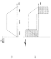
このX軸テーブル移動機能の制御対象に対して、図9(a)に示すような移動速度の速度パターンで指令条件を与えた場合、これを実現するためのX軸のサーボモータの必要駆動トルクは図9(b)に示すような時系列変化パターンとなる。この図9(b)に示す必要駆動トルクパターンは、加速期において回転方向に対する正のトルクが必要であり、また減速期において回転方向に対する負のトルクが必要であることを示している(それぞれ図中の網掛け表示部参照)。なお、定速期においては、摩擦などで生じる動力損失分を補填する程度の一定の低いトルクでよい。また、上記図2における必要駆動トルクパターン演算部112が上記の必要駆動トルクパターンを演算するよう機能する。
このようにして解析された必要駆動トルクパターンに基づき、上記図2における要求特性算出部113が、上記指令条件に対応してX軸のモータ機器に必要とされる最大電流、消費電力、回生エネルギ、必要回生抵抗などの特性、つまり要求特性を算出する。なお、このような必要駆動トルクパターンの実際の波形と要求特性の表示例を図10に示す。そして、この要求特性を必要最小限に満たすモータ機器(サーボモータ、サーボコントローラ)の名称を、上記図2におけるモータ機器選定部114が、上記モータ機器特性データベース121から取得し、図10中の選定名称表示部510で表示することで、ユーザはX軸における適切なモータ機器を選定できる。なお、上記の選定名称表示部が各請求項記載の第3表示部に相当する。
一方、上記図3で示したX-Yテーブル200の多軸駆動システムにおいて、Y1軸とY2軸の場合には、それぞれのテーブル移動機構204、205の制御対象の負荷がX1軸の動作に影響を受けて変動する。具体的には、X軸可動テーブル207がY1軸上に近接するほど、Y1軸の制御対象の負荷質量が増加し、Y2軸の制御対象の負荷質量が減少する。逆に、X軸可動テーブル207がY2軸上に近接するほど、Y2軸の制御対象の負荷質量が増加し、Y1軸の制御対象の負荷質量が減少する。この点を考慮しなければ、Y1軸、Y2軸のモータ機器を適切に選定できない。
例えば、可動梁上で移動するX軸可動テーブル207とその上に設置されるX軸の制御対象を合わせた質量を40kgとし、そのうちY1軸とY2軸のそれぞれで分担して負担する負荷質量をMy1、My2とすると、常にMy1+My2=40kgの関係が成立する。この関係において、上記図3(b)に示したX軸上のx座標で、X軸可動テーブル207が最もY1軸に接近している状態でx=0、X軸可動テーブル207が最もY2軸に接近している状態でx=Lとした座標設定の場合を考える。例えば、x=0のときにY1軸側で負担する分担負荷質量My1が30kg、Y2軸側で負担する分担負荷質量My2が10kgとし、x=LのときにY1軸側で負担する分担負荷質量My1が10kg、Y2軸側で負担する分担負荷質量My2が30kgとする。そして、分担負荷質量My1は移動位置xに対して比例減少し、分担負荷質量My2は移動位置xに対して比例増加する。
この場合に、X軸可動テーブル207とその上に設置されるX軸の制御対象を合わせた質量(40kg)のうちY1軸、Y2軸のそれぞれで負担する分担負荷質量My1、My2は、
My1=20(L-x)/L+10 ・・・ (1)
My2=20x/L+10 ・・・ (2)
と置ける。また、Y1軸テーブル移動機構204及びY2軸テーブル移動機構205がそれぞれ制御対象としている負荷質量は上記(1)式、(2)式で求められる分担負荷質量My1、My2だけではなく、それ以外にもX軸可動テーブル207を除いたX軸テーブル移動機構208と可動梁全体を合わせた負荷質量に対する分担負荷質量Cy1、Cy2との合計値となる(Cy1+Cy2=一定)。しかし、これら分担負荷質量Cy1、Cy2は、それぞれX軸の移動位置xなどの影響を受けずに変動することのない固定値である。その結果、Y1軸テーブル移動機構204及びY2軸テーブル移動機構205がそれぞれ制御対象としている負荷質量MY1、MY2は、
MY1=My1+Cy1=20(L-x)/L+10+Cy1・・・(3)
MY2=My2+Cy2=20x/L+10+Cy2 ・・・ (4)
となる。これら2つの式が、Y1軸テーブル移動機構204とY2軸テーブル移動機構205のそれぞれの制御対象の負荷演算式となり、上記図3のX-Yテーブル200の場合にはそれぞれの負荷演算式がX軸可動テーブル207の移動位置xについての1次式となることが分かる。
My1=20(L-x)/L+10 ・・・ (1)
My2=20x/L+10 ・・・ (2)
と置ける。また、Y1軸テーブル移動機構204及びY2軸テーブル移動機構205がそれぞれ制御対象としている負荷質量は上記(1)式、(2)式で求められる分担負荷質量My1、My2だけではなく、それ以外にもX軸可動テーブル207を除いたX軸テーブル移動機構208と可動梁全体を合わせた負荷質量に対する分担負荷質量Cy1、Cy2との合計値となる(Cy1+Cy2=一定)。しかし、これら分担負荷質量Cy1、Cy2は、それぞれX軸の移動位置xなどの影響を受けずに変動することのない固定値である。その結果、Y1軸テーブル移動機構204及びY2軸テーブル移動機構205がそれぞれ制御対象としている負荷質量MY1、MY2は、
MY1=My1+Cy1=20(L-x)/L+10+Cy1・・・(3)
MY2=My2+Cy2=20x/L+10+Cy2 ・・・ (4)
となる。これら2つの式が、Y1軸テーブル移動機構204とY2軸テーブル移動機構205のそれぞれの制御対象の負荷演算式となり、上記図3のX-Yテーブル200の場合にはそれぞれの負荷演算式がX軸可動テーブル207の移動位置xについての1次式となることが分かる。
このように、連動する多軸間におけるそれぞれの負荷質量について、他の動作軸の動作量(加速度、速度、変位、傾きなど)を用いた演算式で個別に求められる場合が多い。このような関係演算式は、当該多軸駆動システムの機構的構成を把握している設計者のユーザであれば負荷演算式として作成し、上記図5に示した負荷パターン設定操作部504で当該負荷演算式を入力できる。つまり、多軸駆動システムの各動作軸においてそれぞれの制御対象の負荷質量が他の動作軸の動作量と相互に影響を受けて変動しあう場合であっても、負荷演算式を用いて各動作軸の制御対象の負荷質量を見かけ上の固定質量の増減に置換し、個別に算出できる。
例えば上記(3)式で表されるY1軸の負荷演算式の場合には、上述したように制御対象の負荷演算式がX軸可動テーブル207の移動位置xを変数とした1次式であることから、当該移動位置xを求める必要がある。これは、図11に示すように、X軸に対する指令条件として入力された速度パターンに対し機器選定アプリケーション100が内部的に積分演算することで、移動位置xの変化を時系列的に表現した移動量パターンとして求めることができる。なお、この移動量パターンが各請求項記載の移動量の変動に相当する。そして、この移動量パターンに対し、上記図2における負荷パターン演算部111が、上記(3)式の負荷演算式を用いて初期重量負担分(式中の10+Cy1に相当)、慣性モーメント負荷可変係数(式中の20に相当)を考慮した演算を行うことで、Y1軸の制御対象の負荷質量MY1の変化を時系列的に表現した負荷パターンを求めることができる。なお、この負荷パターンが示す内容が各請求項記載の負荷質量の変動に相当する。
本実施形態の例において、Y1軸テーブル移動機構204とY2軸テーブル移動機構205のそれぞれの駆動に適したモータ機器を選定するためには、それぞれの負荷パターンで示される負荷質量をそれぞれの速度パターンで移動させるのに必要な必要駆動トルクパターンと要求特性を求めればよい。以下にその過程の具体例を説明する。
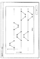
例えば、上記図3に示したX-Yテーブル200を、図12に示すような4段階の工程で動作させた場合を考える。図示する例では、最初にX軸の位置x=Lとし、Y1軸、Y2軸を共に最も手前側に位置させた状態から始めて、X軸だけを位置x=0まで移動させる第1段階目の動作工程を行う。次に、Y1軸、Y2軸の両方を最も奥側まで移動させる第2段階目の動作工程を行う。次に、X軸だけを位置x=Lまで戻すよう移動させる第3段階目の動作工程を行う。次に、Y1軸、Y2軸の両方を最も手前側まで戻すよう移動させる第4段階目の動作工程を行って終了する。以上の4段階の動作工程を行わせるための指令条件として、図示するような速度パターンが入力される。
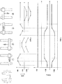
これら速度パターンに基づいて機器選定アプリケーション100が内部的に積分演算してX軸の移動量パターンを算出し(図示省略)、このX軸の移動量パターンに基づいて上記図2における負荷パターン演算部111が各動作軸の負荷演算式を用いて図13に示す負荷パターンを演算する。さらに、これら負荷パターンに基づいて、上記図2における必要駆動トルクパターン演算部112が機構条件を考慮して図14に示す必要駆動トルクパターンを演算する。
このようにして解析された各動作軸の必要駆動トルクパターンに基づいて上記図2における要求特性算出部113がそれぞれの要求特性を算出する。そして、上記図2におけるモータ機器選定部114が、それぞれの要求特性を必要最小限に満たすモータ機器を上記モータ機器特性データベース121から選定し、それらの名称を表示する。
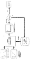
以上の選定処理の工程を模式的にまとめると、図15に示す図となる。すなわち、指令条件として入力された速度パターンと、内部演算した各動作軸の移動量パターン及び入力された負荷演算式から求めた負荷パターンと、に基づいて必要駆動トルクパターンを演算する。この演算では入力された機構条件を考慮する。そして算出された必要駆動トルクパターンに基づいて要求特性が算出され、この要求特性を必要最小限に満たすモータ機器を選定することで選定処理が完了する。本実施形態では、多軸駆動システムに対してこのようなモータ機器の選定処理を各動作軸ごとに個別に行うことができる。
なお、上記図4に示したエンコーダなどの周辺機器の選定については、モータ機器特性データベース121に対応する周辺機器の名称と要求特性も対応づけて記憶させておき、上記の要求特性を算出する際に当該周辺機器についての要求特性も算出して適合するものをモータ機器特性データベース121から選定すればよい。また、特に図示しないが、要求特性に適合するモータ機器が複数ある場合には、それら全ての名称を一覧表示してユーザに選択させてもよい。
図16は、以上説明した本実施形態によるモータ機器の選定処理を実現するために、PC1のCPUが実行する制御内容を表すフローチャートの一例である。なお、このフローは、機器選定アプリケーション100の起動時から開始される。
まずステップS5で、上記図2に示した軸数入力部131が、上記図5の軸数入力操作部501を介したユーザからの入力操作により、設計対象の多軸駆動システム(上記図3のX-Yテーブル200)の軸数を設定する。
次にステップS10へ移り、上記図2に示した指令条件入力部132が、上記図5の速度線図設定操作部502を介したユーザからの入力操作により、各動作軸の制御対象の速度パターンを設定する(実際の設定操作画面は上記図6、図7参照)。
次にステップS15へ移り、上記図2に示した機構条件入力部133が、上記図5の機構設定操作部503を介したユーザからの入力操作により、各動作軸の機構条件を設定する(実際の設定操作画面は上記図8参照)。
次にステップS20へ移り、上記図2に示した負荷演算式入力部134が、上記図5の負荷パターン設定操作部504を介したユーザからの入力操作により、各動作軸の負荷演算式を設定する。
次にステップS25へ移り、上記図2に示した負荷パターン演算部111が、上記図11、図13で説明した処理により各動作軸の負荷パターンを演算する。
次にステップS30へ移り、上記図2に示した必要駆動トルクパターン演算部112が、上記図14で説明した処理により各動作軸の必要駆動トルクパターンを演算する。
次にステップS35へ移り、上記図2に示した要求特性算出部113が、各動作軸の必要駆動トルクパターンから対応するモータ機器の要求特性を算出する。
次にステップS40へ移り、上記図2に示したモータ機器選定部114が、モータ機器特性データベース121を参照して各動作軸の要求特性に適合するモータ機器を選定する。
次にステップS45へ移り、上記図2に示した出力部140が、上記ステップS40で選定した各動作軸のモータ機器の名称を表示する。そして、このフローを終了する。
なお、上記ステップS10、ステップS15、ステップS20の手順でそれぞれで行う設定は、ユーザの任意の順序で設定してもよい。
以上において、上記図16のフローにおけるステップS10の手順が各請求項記載の第1表示制御手順、第1表示手順に相当し、ステップS15の手順が各請求項記載の第2表示制御手順、第5表示制御手順、第2表示手順に相当し、ステップS25の手順が各請求項記載の負荷パターン算出手順、負荷パターン演算制御手順、負荷パターン演算手順に相当し、ステップS30の手順が各請求項記載の必要駆動トルクパターン演算制御手順、必要駆動トルクパターン演算手順に相当し、ステップS45の手順が各請求項記載の第3表示制御手順、機器選定制御手順、第3表示手順、機器選定手順に相当する。
以上説明したように、本実施形態の機器選定アプリケーション100によれば、各被駆動機構が負担する負荷質量の変動を加味しつつ、各被駆動機構に最適なサーボモータ及びモータ制御装置を含む周辺機器を選定することができる。まず、ユーザが複数の被駆動機構に対応した複数の動作軸それぞれごとに制御対象の速度パターン、機構条件を設定する。また、ユーザは必要な動作軸に対して負荷演算式を設定する。これにより、各動作軸それぞれの制御対象の負荷質量のうち、他の動作軸と連動して動作するときに分担して負担する分の分担負荷質量の変動を負荷演算式から求め、それに基づいて当該動作軸単独の制御対象の負荷質量の変動が算出される(分担負荷質量が一定の場合もあり)。この負荷質量の変動と速度パターンとに基づいて、当該動作軸の必要駆動トルクパターンと要求特性が算出される。この要求特性に基づき、予め用意された複数のサーボモータ及び複数のサーボコントローラの中から、上記要求特性に適合した少なくとも1つのサーボモータ及び少なくとも1つのサーボコントローラのそれぞれが選定され、それらの名称が一覧表示される。
この結果、ユーザは、設計対象の多軸駆動システムにおいて各被駆動機構が負担する質量負荷の変動を加味しつつ、上記一覧表示されたサーボモータ及びサーボコントローラの中から、過不足のない適正なスペックを備えたサーボモータ及びサーボコントローラを容易に選定することができる。
また、本実施形態によれば、負荷パターン演算部111により算出された制御対象の負荷質量の変動を表す負荷パターンと、設定された速度パターンとを用いて、当該動作軸の必要駆動トルクパターンと要求特性が算出される。これにより、過不足のない適正なスペックを備えたサーボモータ及びサーボコントローラを確実に選定することができる。
また、本実施形態によれば、ある被駆動機構によって行われる制御対象の動作によって実際に生じる負荷質量の移動が、別の被駆動機構が負担する制御対象の見かけの固定質量の増減に換算される。すなわち、一定の値を備えた負荷質量が移動する現象を、固定点に位置する仮想的な負荷質量の値が増減する現象に置き換えて、算出が行われる。これにより、負荷パターン演算部111は、複雑な計算を行うことなく、上記負荷パターンを求めることができる。
また、本実施形態によれば、負荷パターン演算部111は、X軸に対応して設定された速度パターンを積分して求められたX軸の移動量パターンに所定の負荷可変係数(慣性モーメント負荷可変係数)を乗じ、X軸の被駆動機構が負担する制御対象の負荷質量の初期重量負担分を加えることにより、Y1軸、Y2軸のそれぞれの負荷パターンへの換算を行う。これにより、負荷パターン演算部111は、複雑な計算を行うことなく、負荷パターンを確実に精度よく求めることができる。
なお、上記実施形態では、サーボコントローラについてもサーボモータと1対1で対応させて選定した。つまり、単軸サーボコントローラを選定する場合を説明した。しかし本発明はこれに限られず、他にも複数のサーボモータをまとめて制御する多軸サーボコントローラの選定にも利用できる。例えば、上記の多軸選定操作部507の操作により表示される図17に示すように、各動作軸の必要駆動トルクパターンを同一時間軸上にまとめて同時に実現可能な要求特性(最大電流、消費電力など)を算出し、それに適合する多軸サーボコントローラや多軸共通コンバータを選定してもよい。もしくは、図18に示すように、各動作軸それぞれで適合する単軸サーボコントローラを選定し、それら複数の単軸サーボコントローラをまとめた特性の多軸サーボコントローラや多軸共通コンバータを選定してもよい。なお、このように複数の被駆動機構すべてに対応して推奨される少なくとも1つのサーボコントローラを選定して表示する画面が各請求項記載の第4表示部に相当し、当該表示画面を表示させる制御手順が各請求項記載の第4表示制御手順に相当する。
これにより、各動作軸ごとに適正なスペックが選定された後、さらに全動作軸(すなわち複数の被駆動機構すべて)に対して1台で制御する場合に最適な多軸サーボコントローラ、多軸共通コンバータを改めてユーザに対し推奨することができる。
また、本実施形態によれば、複数の被駆動機構の動作軸それぞれについて、上記図6の設定画面でそれぞれ設定された複数の速度パターンを、同一時間軸上に並べて表示する上記図7の設定画面を表示する。なお、上記図7の設定画面が各請求項記載の第5表示部に相当する。これにより、ユーザが各動作軸ごとにいずれか1つの速度パターンを選択する際、各動作軸ごとの対比や連動タイミングを容易に確認できるので、さらに利便性を向上することができる。
また、本実施形態によれば、複数の被駆動機構として、負荷質量に対し動作軸としてのX軸に沿う直線移動を行うX軸テーブル移動機構208と、X軸テーブル移動機構208の一端部を支持し当該一端部に対し動作軸としてのY1軸に沿う直線移動を行うY1軸テーブル移動機構204と、X軸テーブル移動機構208の他端部を支持し当該他端部に対し動作軸としての前記Y1軸と平行なY2軸に沿う直線移動を行うY2軸テーブル移動機構205と、を有するX-Yテーブル200の多軸駆動システムにおけるサーボモータの選定を行う。
これにより、X軸に沿って制御対象を移動させるX軸テーブル移動機構208の両端部を、Y1軸テーブル移動機構204及びY2軸テーブル移動機構205によってY1軸及びY2軸方向に直線移動させる3軸駆動システムに対し、過不足のない適正なスペックを備えたサーボモータ及びサーボコントローラを容易に選定することができる。
なお、上記指令条件は速度パターンの入力に限られず、制御対象の移動位置パターン(移動量パターン)などの他の動作量で入力してもよい。
なお、本発明は、上記実施形態に限られるものではなく、その趣旨及び技術的思想を逸脱しない範囲内で種々の変形が可能である。以下、そのような変形例を順を追って説明する。
(1)複雑な負荷パターンを外部アプリケーションで算出する場合
上記実施形態においては、多軸駆動システムの例としてY1軸とY2軸の2軸を共通のX軸に対して並列に連結した単純な構成の場合で説明した。しかし、図19の左側に示すように複数の動作軸を直列に連結して一端を自由端とした構成のアームマニピュレータ600のような多軸駆動システムの場合は、多数のマトリクスの積算などにより各動作軸に対応する負荷パターンの演算が非常に難しくなる。このように複数の動作軸それぞれの負荷パターンの演算が複雑で困難な場合には、専用の外部解析アプリケーションで負荷パターンの演算を行い、その結果をインポートして利用する処理としてもよい。
上記実施形態においては、多軸駆動システムの例としてY1軸とY2軸の2軸を共通のX軸に対して並列に連結した単純な構成の場合で説明した。しかし、図19の左側に示すように複数の動作軸を直列に連結して一端を自由端とした構成のアームマニピュレータ600のような多軸駆動システムの場合は、多数のマトリクスの積算などにより各動作軸に対応する負荷パターンの演算が非常に難しくなる。このように複数の動作軸それぞれの負荷パターンの演算が複雑で困難な場合には、専用の外部解析アプリケーションで負荷パターンの演算を行い、その結果をインポートして利用する処理としてもよい。
その場合に指令条件、機構条件、及び負荷演算式(例えばニュートンオイラー法による演算式やラグランジュ運動方程式など)の入力は、当該機器選定アプリケーション100Aで入力して外部解析アプリケーションにエクスポートしてもよいし、外部解析アプリケーションに直接入力してもよい。そして本変形例の機器選定アプリケーション100Aが、外部解析アプリケーションから演算された各動作軸の負荷パターンと速度パターンの組み合わせをインポートし、それらに基づいて各動作軸の必要駆動トルクパターンを演算する。各動作軸の必要駆動トルクパターンからそれぞれ対応する要求特性を算出し、それぞれ適合するモータ機器の名称を選定すればよい。
以上において、外部解析アプリケーションから負荷パターンと速度パターンの組み合わせを各被駆動機構ごとに取得する処理ブロックが各請求項記載の組み合わせ取得部、組み合わせ取得手順に相当し、各動作軸の機構条件を入力する操作画面が各請求項記載の第6表示部に相当し、この操作画面を表示する制御手順が各請求項記載の第6表示制御手順、第4表示手順に相当し、取得した負荷パターンと速度パターンの組み合わせに基づいて選定したモータ機器の名称を表示する画面が各請求項記載の第7表示部に相当し、この表示画面を表示する制御手順が各請求項記載の第7表示制御手順、第5表示手順に相当する。
以上説明したように、本変形例の機器選定アプリケーション100Aによれば、複雑な構成の多軸駆動システムにおける各動作軸の負荷パターンの速度パターンの組み合わせを外部解析アプリケーションから取得できるため、当該機器選定アプリケーション100A自体は簡易な構成のまま上記実施形態と同様に各動作軸の過不足のない適正なスペックを備えたサーボモータ及びサーボコントローラを容易に選定することができる。
なお、外部解析アプリケーションからは負荷パターンだけをインポートし、同じ動作軸の組み合わせの速度パターンは当該機器選定アプリケーション100Aで入力して取得してもよい。
なお、上記実施形態や各変形例では、機器選定アプリケーション100、100AがPC1のHDDなどの内部記憶装置に格納されたプログラムで起動するスタンドアローンアプリケーションの形態として説明したが、他にもネットワークを介して外部サーバに接続した際に起動するネットアプリケーション(WEBアプリケーション)の形態としてもよい。
また、以上既に述べた以外にも、上記実施形態や各変形例による手法を適宜組み合わせて利用しても良い。
その他、一々例示はしないが、その趣旨を逸脱しない範囲内において、種々の変更が加えられて実施されるものである。
1 パーソナルコンピュータ(モータ機器選定装置)
100,100A 機器選定アプリケーション(機器選定処理プログラム)
110 選定演算部
111 負荷パターン演算部
112 必要駆動トルクパターン演算部
113 要求特性算出部(機器選定部)
114 モータ機器選定部
120 記憶部
121 モータ機器特性データベース
122 被駆動機構モデル記憶部
130 入力部
131 軸数入力部
132 指令条件入力部
133 機構条件入力部
134 負荷演算式入力部
140 出力部
200 X-Yテーブル
202 Y1軸可動テーブル
203 Y2軸可動テーブル
204 Y1軸テーブル移動機構(Y1軸移動機構)
205 Y2軸テーブル移動機構(Y2軸移動機構)
206 可動梁
207 X軸可動テーブル
208 X軸テーブル移動機構(X軸被駆動機構)
400 テーブル移動機構
410 モータ駆動機構
411 サーボモータ
412 エンコーダ
413 サーボコントローラ(モータ制御装置)
420 被駆動機構
421 カップリング
422 減速機
423 カップリング
424 水平ボールねじ機構
430 制御対象
501 軸数入力操作部
502 速度線図設定操作部
503 機構設定操作部
504 負荷パターン設定操作部
505 単軸設定操作部
506 多軸速度線図設定操作部
507 多軸選定操作部
510 選定名称表示部
100,100A 機器選定アプリケーション(機器選定処理プログラム)
110 選定演算部
111 負荷パターン演算部
112 必要駆動トルクパターン演算部
113 要求特性算出部(機器選定部)
114 モータ機器選定部
120 記憶部
121 モータ機器特性データベース
122 被駆動機構モデル記憶部
130 入力部
131 軸数入力部
132 指令条件入力部
133 機構条件入力部
134 負荷演算式入力部
140 出力部
200 X-Yテーブル
202 Y1軸可動テーブル
203 Y2軸可動テーブル
204 Y1軸テーブル移動機構(Y1軸移動機構)
205 Y2軸テーブル移動機構(Y2軸移動機構)
206 可動梁
207 X軸可動テーブル
208 X軸テーブル移動機構(X軸被駆動機構)
400 テーブル移動機構
410 モータ駆動機構
411 サーボモータ
412 エンコーダ
413 サーボコントローラ(モータ制御装置)
420 被駆動機構
421 カップリング
422 減速機
423 カップリング
424 水平ボールねじ機構
430 制御対象
501 軸数入力操作部
502 速度線図設定操作部
503 機構設定操作部
504 負荷パターン設定操作部
505 単軸設定操作部
506 多軸速度線図設定操作部
507 多軸選定操作部
510 選定名称表示部
Claims (21)
- サーボモータの駆動力に基づき、複数の被駆動機構が互いに連動して動作する多軸駆動システムにおける、前記サーボモータ及びモータ制御装置を含む周辺機器の選定を行う機器選定装置であって、
各動作軸ごとに、予め用意された複数の速度パターンから1つの速度パターンの選択を促す表示を行う、第1表示部と、
各動作軸ごとに、予め用意された前記複数の被駆動機構から1つの前記被駆動機構の選択を促す表示を行う、第2表示部と、
各動作軸ごとに、前記第2表示部における表示に対応した前記被駆動機構の選択結果に応じ、当該選択された1つの被駆動機構が他の被駆動機構と連動して動作するときに当該1つの被駆動機構が負担する負荷質量の変動、及び、当該1つの被駆動機構に関わる前記速度パターンの選択結果、に適合する少なくとも1つのサーボモータ及び少なくとも1つのモータ制御装置を、予め用意された複数のサーボモータ及び複数のモータ制御装置の中から抽出してそれらの名称を一覧表示し、その一覧表示の中からの選択を促す表示を行う、第3表示部と、
を有することを特徴とする機器選定装置。 - 請求項1記載の機器選定装置において、
各動作軸ごとに、前記第1表示部における表示に対応した前記速度パターンの選択結果及び前記第2表示部における表示に対応した前記被駆動機構の選択結果に応じ、前記選択された前記1つの被駆動機構が前記他の被駆動機構と連動して動作するときに負担する前記負荷質量の変動を、算出する負荷パターン算出部を有し、
前記第3表示部は、
前記負荷パターン算出部により算出された前記負荷質量の変動と前記速度パターンの選択結果とに適合する、前記少なくとも1つのサーボモータ及び前記少なくとも1つのモータ制御装置を抽出してそれらの名称を一覧表示する
ことを特徴とする機器選定装置。 - 請求項2記載の機器選定装置において、
前記負荷パターン算出部は、
前記他の被駆動機構により前記負荷質量が移動するとき、当該負荷質量の移動を、前記1つの被駆動機構により負担する見かけ上の固定質量の増減に置換することにより、前記算出を行う
ことを特徴とする機器選定装置。 - 請求項3記載の機器選定装置において、
前記負荷パターン算出部は、
前記負荷質量の移動に影響する前記他の被駆動機構に対応して選択された前記選択結果に関わる前記速度パターンを積分して求められた移動量の変動に所定の負荷可変係数を乗じ、前記1つの被駆動機構が負担する前記負荷質量の初期重量負担分を加えることにより、前記換算を行う
ことを特徴とする機器選定装置。 - 請求項1乃至請求項4のいずれか1項記載の機器選定装置において、
各動作軸に関する前記第1表示部、前記第2表示部、前記第3表示部での表示、及び、各表示に対応した各選択結果、に応じて、前記複数の被駆動機構すべてに対応して推奨される少なくとも1つのモータ制御装置を表示する第4表示部
を有することを特徴とする機器選定装置。 - 請求項1乃至請求項5のいずれか1項記載の機器選定装置において、
前記複数の被駆動機構の前記動作軸それぞれについて、前記第1表示部における表示に対応してそれぞれ選択された複数の前記速度パターンを、同一時間軸上に並べて表示する第5表示部を有することを特徴とする機器選定装置。 - 請求項1乃至請求項6のいずれか1項記載の機器選定装置において、
前記複数の被駆動機構として、負荷質量に対し前記動作軸としてのX軸に沿う直線移動を行うX軸被駆動機構と、前記X軸被駆動機構の一端部を支持し当該一端部に対し前記動作時としてのY1軸に沿う直線移動を行うY1軸移動機構と、前記X軸被駆動機構の他端部を支持し当該他端部に対し前記動作軸としての前記Y1軸と平行なY2軸に沿う直線移動を行うY2軸移動機構と、を有する多軸駆動システムにおける前記サーボモータの選定を行う、ことを特徴とする機器選定装置。 - サーボモータの駆動力に基づき、複数の被駆動機構が互いに連動して動作する多軸駆動システムにおける、前記サーボモータ及びモータ制御装置を含む周辺機器の選定を行う機器選定装置であって、
前記多軸駆動システムが所定の複数の動作態様を行うときの各動作態様ごとに予め求められている、1つの被駆動機構が他の被駆動機構に連動して動作するときに負担する負荷質量の変動と当該1つの被駆動機構に関わる速度パターンとの組合せを、各被駆動機構ごとに取得する組み合わせ取得部と、
各動作軸ごとに、予め用意された前記複数の被駆動機構から1つの前記被駆動機構の選択を促す表示を行う、第6表示部と、
各動作軸ごとに、前記第6表示部における表示に対応した前記被駆動機構の選択結果、及び、当該選択された1つの被駆動機構に関する前記組み合わせ取得部での取得結果、に適合する少なくとも1つのサーボモータ及び少なくとも1つのモータ制御装置を、予め用意された複数のサーボモータ及び複数のモータ制御装置の中から抽出してそれらの名称を一覧表示し、その一覧表示の中からの選択を促す表示を行う、第7表示部と、
を有することを特徴とする機器選定装置。 - それぞれ個別のサーボモータにより駆動される複数の被駆動機構が互いに連動して動作する多軸駆動システムに対し、その設計上で前記サーボモータ及びモータ制御装置を含む周辺機器の選定を行う機器選定装置であって、
前記複数の被駆動機構のうち選択された1つの被駆動機構が動作させる対象の負荷が、他の被駆動機構の動作に基づいて変動する態様を表す負荷パターンを演算する負荷パターン演算部と、
前記1つの被駆動機構がその動作で前記負荷パターンで示される負荷を動作させるために、前記1つの被駆動機構を駆動する前記サーボモータに必要とされる必要駆動トルクパターンを演算する必要駆動トルクパターン演算部と、
前記必要駆動トルクパターンに基づいて、前記1つの被駆動機構の駆動に適合するサーボモータ及びモータ制御装置を選定する機器選定部と、
を有することを特徴とする機器選定装置。 - サーボモータの駆動力に基づき、複数の被駆動機構が互いに連動して動作する多軸駆動システムにおける、前記サーボモータ及びモータ制御装置を含む周辺機器の選定を行うとともに、所定の演算を行う演算部及び所定の表示を行う表示部を備えた、機器選定装置の前記演算部に対し、
各動作軸ごとに、予め用意された複数の速度パターンから1つの速度パターンの選択を促す表示を行うための制御信号を、前記表示部に出力する第1表示制御手順と、
各動作軸ごとに、予め用意された前記複数の被駆動機構から1つの前記被駆動機構の選択を促す表示を行うための制御信号を、前記表示部に出力する第2表示制御手順と、
各動作軸ごとに、前記第2表示制御手順の前記表示部の表示に対応した前記被駆動機構の選択結果に応じ、当該選択された1つの被駆動機構が他の被駆動機構と連動して動作するときに当該1つの被駆動機構が負担する負荷質量の変動、及び、当該1つの被駆動機構に関わる前記速度パターンの選択結果、に適合する少なくとも1つのサーボモータ及び少なくとも1つのモータ制御装置を、予め用意された複数のサーボモータ及び複数のモータ制御装置の中から抽出してそれらの名称を一覧表示し、その一覧表示の中からの選択を促す表示を行うための制御信号を、前記表示部に出力する第3表示制御手順と、
を実行させることを特徴とする、機器選定処理プログラム。 - 請求項10記載の機器選定処理プログラムにおいて、
前記演算部に対し、さらに、
各動作軸ごとに、前記第1表示部における表示に対応した前記速度パターンの選択結果及び前記第2表示部における表示に対応した前記被駆動機構の選択結果に応じ、前記選択された前記1つの被駆動機構が前記他の被駆動機構と連動して動作するときに負担する前記負荷質量の変動を、算出する負荷パターン算出手順を実行させ、
前記第3表示制御手順は、
前記負荷パターン算出部により算出された前記負荷質量の変動と前記速度パターンの選択結果とに適合する、前記少なくとも1つのサーボモータ及び前記少なくとも1つのモータ制御装置を抽出してそれらの名称を一覧表示するための制御信号を出力する
ことを特徴とする機器選定処理プログラム。 - 請求項11記載の機器選定処理プログラムにおいて、
前記負荷パターン算出手順は、
前記他の被駆動機構により移動する負荷質量を、前記1つの被駆動機構が負担する前記負荷質量の変動に換算して前記算出を行う
ことを特徴とする機器選定処理プログラム。 - 請求項12記載の機器選定処理プログラムにおいて、
前記負荷パターン算出手順は、
前記負荷質量の移動に影響する前記他の被駆動機構に対応して選択された前記選択結果に関わる前記速度パターンを積分して求められた移動量の変動に所定の負荷可変係数を乗じ、前記1つの被駆動機構が負担する前記負荷質量の初期重量負担分を加えることにより、前記換算を行う
ことを特徴とする機器選定処理プログラム。 - 請求項10乃至請求項13のいずれか1項記載の機器選定処理プログラムにおいて、
前記演算部に対し、さらに、
各動作軸に関する前記第1表示制御手順、前記第2表示制御手順、前記第3表示制御手順での表示、及び、各表示に対応した各選択結果、に応じて、前記複数の被駆動機構すべてに対応して推奨される少なくとも1つのモータ制御装置を表示する第4表示制御手順
を有することを特徴とする機器選定処理プログラム。 - 請求項10乃至請求項14のいずれか1項記載の機器選定処理プログラムにおいて、
前記演算部に対し、さらに
前記複数の被駆動機構の前記動作軸それぞれについて、前記第1表示制御手順における表示に対応してそれぞれ選択された複数の前記速度パターンを、同一時間軸上に並べて表示する第5表示制御手順を有することを特徴とする機器選定処理プログラム。 - 請求項10乃至請求項15のいずれか1項記載の機器選定処理プログラムにおいて、
前記複数の被駆動機構として、負荷質量に対し前記動作軸としてのX軸に沿う直線移動を行うX軸被駆動機構と、前記X軸被駆動機構の一端部を支持し当該一端部に対し前記動作時としてのY1軸に沿う直線移動を行うY1軸移動機構と、前記X軸被駆動機構の他端部を支持し当該他端部に対し前記動作軸としての前記Y1軸と平行なY2軸に沿う直線移動を行うY2軸移動機構と、を有する多軸駆動システムにおける前記サーボモータの選定を行う、ことを特徴とする機器選定処理プログラム。 - サーボモータの駆動力に基づき、複数の被駆動機構が互いに連動して動作する多軸駆動システムにおける、前記サーボモータ及びモータ制御装置を含む周辺機器の選定を行うとともに、所定の演算を行う演算部及び所定の表示を行う表示部を備えた、機器選定装置の前記演算部に対し、
前記多軸駆動システムが所定の複数の動作態様を行うときの各動作態様ごとに予め求められている、1つの被駆動機構が他の被駆動機構に連動して動作するときに負担する負荷質量の変動と当該1つの被駆動機構に関わる速度パターンとの組合せを、各被駆動機構ごとに取得する組み合わせ取得手順と、
各動作軸ごとに、予め用意された前記複数の被駆動機構から1つの前記被駆動機構の選択を促す表示を行うための制御信号を、前記表示部に出力する第6表示制御手順と、
各動作軸ごとに、前記第6表示制御手順の前記表示部の表示に対応した前記被駆動機構の選択結果、及び、当該選択された1つの被駆動機構に関する前記組み合わせ手順での取得結果、に適合する少なくとも1つのサーボモータ及び少なくとも1つのモータ制御装置を、予め用意された複数のサーボモータ及び複数のモータ制御装置の中から抽出してそれらの名称を一覧表示し、その一覧表示の中からの選択を促す表示を行うための制御信号を、前記表示部に出力する第7表示制御手順と、
を有することを特徴とする機器選定処理プログラム。 - それぞれ個別のサーボモータにより駆動される複数の被駆動機構が互いに連動して動作する多軸駆動システムに対し、その設計上で前記サーボモータ及びモータ制御装置を含む周辺機器の選定を行う機器選定装置の演算部に対し、
前記複数の被駆動機構のうち選択された1つの被駆動機構が動作させる対象の負荷が、他の被駆動機構の動作に基づいて変動する態様を表す負荷パターンを演算する負荷パターン演算制御手順と、
前記1つの被駆動機構がその動作で前記負荷パターンで示される負荷を動作させるために、前記1つの被駆動機構を駆動する前記サーボモータに必要とされる必要駆動トルクパターンを演算する必要駆動トルクパターン演算制御手順と、
前記必要駆動トルクパターンに基づいて、前記1つの被駆動機構の駆動に適合するサーボモータ及びモータ制御装置を選定する機器選定制御手順と、
を実行させることを特徴とする機器選定プログラム。 - サーボモータの駆動力に基づき、複数の被駆動機構が互いに連動して動作する多軸駆動システムにおける、前記サーボモータ及びモータ制御装置を含む周辺機器の選定を行う機器選定装置が実行する機器選定処理方法であって、
各動作軸ごとに、予め用意された複数の速度パターンから1つの速度パターンの選択を促す表示を行う第1表示手順と、
各動作軸ごとに、予め用意された前記複数の被駆動機構から1つの前記被駆動機構の選択を促す表示を行う第2表示手順と、
各動作軸ごとに、前記第2表示手順の表示に対応した前記被駆動機構の選択結果に応じ、当該選択された1つの被駆動機構が他の被駆動機構と連動して動作するときに当該1つの被駆動機構が負担する負荷質量の変動、及び、当該1つの被駆動機構に関わる前記速度パターンの選択結果、に適合する少なくとも1つのサーボモータ及び少なくとも1つのモータ制御装置を、予め用意された複数のサーボモータ及び複数のモータ制御装置の中から抽出してそれらの名称を一覧表示し、その一覧表示の中からの選択を促す表示を行う、第3表示手順と、
を有することを特徴とする、機器選定処理方法。 - サーボモータの駆動力に基づき、複数の被駆動機構が互いに連動して動作する多軸駆動システムにおける、前記サーボモータ及びモータ制御装置を含む周辺機器の選定を行う機器選定装置が実行する機器選定処理方法であって、
前記多軸駆動システムが所定の複数の動作態様を行うときの各動作態様ごとに予め求められている、1つの被駆動機構が他の被駆動機構に連動して動作するときに負担する負荷質量の変動と当該1つの被駆動機構に関わる速度パターンとの組合せを、各被駆動機構ごとに取得する組み合わせ取得手順と、
各動作軸ごとに、予め用意された前記複数の被駆動機構から1つの前記被駆動機構の選択を促す表示を行う、第4表示手順と、
各動作軸ごとに、前記第4表示手順の表示に対応した前記被駆動機構の選択結果、及び、当該選択された1つの被駆動機構に関する前記組み合わせ手順での取得結果、に適合する少なくとも1つのサーボモータ及び少なくとも1つのモータ制御装置を、予め用意された複数のサーボモータ及び複数のモータ制御装置の中から抽出してそれらの名称を一覧表示し、その一覧表示の中からの選択を促す表示を行う、第5表示手順と、
を有することを特徴とする機器選定処理方法。 - それぞれ個別のサーボモータにより駆動される複数の被駆動機構が互いに連動して動作する多軸駆動システムに対し、その設計上で前記サーボモータ及びモータ制御装置を含む周辺機器の選定を行う機器選定装置が実行する機器選定処理方法であって、
前記複数の被駆動機構のうち選択された1つの被駆動機構が動作させる対象の負荷が、他の被駆動機構の動作に基づいて変動する態様を表す負荷パターンを演算する負荷パターン演算手順と、
前記1つの被駆動機構がその動作で前記負荷パターンで示される負荷を動作させるために、前記1つの被駆動機構を駆動する前記サーボモータに必要とされる必要駆動トルクパターンを演算する必要駆動トルクパターン演算手順と、
前記必要駆動トルクパターンに基づいて、前記1つの被駆動機構の駆動に適合するサーボモータ及びモータ制御装置を選定する機器選定手順と、
を有することを特徴とする機器選定処理方法。
Priority Applications (3)
| Application Number | Priority Date | Filing Date | Title |
|---|---|---|---|
| PCT/JP2012/075711 WO2014054142A1 (ja) | 2012-10-03 | 2012-10-03 | 機器選定装置、及び機器選定処理プログラム、並びに機器選定処理方法 |
| JP2014539531A JP6015979B2 (ja) | 2012-10-03 | 2012-10-03 | 機器選定装置、及び機器選定処理プログラム、並びに機器選定処理方法 |
| US14/678,324 US20150212518A1 (en) | 2012-10-03 | 2015-04-03 | Equipment selection device, equipment selection processing program, and equipment selection processing |
Applications Claiming Priority (1)
| Application Number | Priority Date | Filing Date | Title |
|---|---|---|---|
| PCT/JP2012/075711 WO2014054142A1 (ja) | 2012-10-03 | 2012-10-03 | 機器選定装置、及び機器選定処理プログラム、並びに機器選定処理方法 |
Related Child Applications (1)
| Application Number | Title | Priority Date | Filing Date |
|---|---|---|---|
| US14/678,324 Continuation US20150212518A1 (en) | 2012-10-03 | 2015-04-03 | Equipment selection device, equipment selection processing program, and equipment selection processing |
Publications (1)
| Publication Number | Publication Date |
|---|---|
| WO2014054142A1 true WO2014054142A1 (ja) | 2014-04-10 |
Family
ID=50434501
Family Applications (1)
| Application Number | Title | Priority Date | Filing Date |
|---|---|---|---|
| PCT/JP2012/075711 Ceased WO2014054142A1 (ja) | 2012-10-03 | 2012-10-03 | 機器選定装置、及び機器選定処理プログラム、並びに機器選定処理方法 |
Country Status (3)
| Country | Link |
|---|---|
| US (1) | US20150212518A1 (ja) |
| JP (1) | JP6015979B2 (ja) |
| WO (1) | WO2014054142A1 (ja) |
Cited By (12)
| Publication number | Priority date | Publication date | Assignee | Title |
|---|---|---|---|---|
| JP2017093209A (ja) * | 2015-11-13 | 2017-05-25 | ファナック株式会社 | 電動機システムを選定するための選定装置、およびネットワークシステム |
| JP2017093265A (ja) * | 2015-11-17 | 2017-05-25 | ファナック株式会社 | 電動機システムを選定する選定装置およびネットワークシステム |
| JP2017220991A (ja) * | 2016-06-03 | 2017-12-14 | 株式会社安川電機 | モータ選定プログラム、モータ選定方法、モータ制御装置選定プログラム、及び機械システム |
| JP2018153046A (ja) * | 2017-03-14 | 2018-09-27 | ファナック株式会社 | アンプ選択装置、アンプ選択方法、及びアンプ選択プログラム |
| JP6448877B1 (ja) * | 2018-01-31 | 2019-01-09 | 三菱電機株式会社 | 電動機の容量選定装置、容量選定方法および容量選定プログラム |
| JP2019057962A (ja) * | 2017-09-19 | 2019-04-11 | ファナック株式会社 | 電源容量表示機能を有するアンプ選択装置、アンプ選択方法、及びアンプ選択プログラム |
| CN109698642A (zh) * | 2019-02-21 | 2019-04-30 | 广东工业大学 | 一种伺服电机控制方法及系统 |
| DE102019001794A1 (de) | 2018-04-16 | 2019-10-17 | Fanuc Corporation | Motorkonfigurationsauswahlvorrichtung, motorkonfigurationsauswahlverfahren und programm |
| JP2020054104A (ja) * | 2018-09-26 | 2020-04-02 | ファナック株式会社 | 複数のコンバータユニットを有するシステムにおけるサーボアンプ選定装置 |
| JP2023183324A (ja) * | 2022-06-15 | 2023-12-27 | オリエンタルモーター株式会社 | 電動機選定装置および電動機選定プログラム |
| WO2024134781A1 (ja) * | 2022-12-20 | 2024-06-27 | ファナック株式会社 | 評価装置及び評価方法 |
| WO2026009306A1 (ja) * | 2024-07-02 | 2026-01-08 | ファナック株式会社 | サーボ部品選定装置 |
Families Citing this family (6)
| Publication number | Priority date | Publication date | Assignee | Title |
|---|---|---|---|---|
| WO2013145296A1 (ja) * | 2012-03-30 | 2013-10-03 | 三菱電機株式会社 | サーボ選定システム |
| JP6378384B1 (ja) | 2017-03-14 | 2018-08-22 | ファナック株式会社 | モータ選定方法及びモータ選定プログラム |
| US10622927B2 (en) | 2017-08-30 | 2020-04-14 | Mitsubishi Electric Corporation | Parameter selection support system, parameter selection support method, and parameter selection support program |
| CN114696720A (zh) * | 2018-03-28 | 2022-07-01 | 三菱电机株式会社 | 选定装置及选定方法 |
| CN118713815B (zh) * | 2024-08-28 | 2024-11-12 | 深圳市纽创信安科技开发有限公司 | 数据处理系统和方法 |
| CN119717728B (zh) * | 2024-12-19 | 2025-12-12 | 南方电网调峰调频发电有限公司检修试验分公司 | 机组工况控制方法、装置、计算机设备、计算机可读存储介质和计算机程序产品 |
Citations (4)
| Publication number | Priority date | Publication date | Assignee | Title |
|---|---|---|---|---|
| JP2006042589A (ja) * | 2004-06-24 | 2006-02-09 | Yaskawa Electric Corp | サーボモータ選定装置、サーボモータ選定方法、プログラムおよび記録媒体 |
| JP2006260350A (ja) * | 2005-03-18 | 2006-09-28 | Matsushita Electric Ind Co Ltd | モータ容量選定方法 |
| WO2008139800A1 (ja) * | 2007-05-15 | 2008-11-20 | Kabushiki Kaisha Yaskawa Denki | 電動機制御装置の選定装置、電動機制御装置の選定方法、該方法を実現するコンピュータプログラム、及びその記憶媒体 |
| JP2010193687A (ja) * | 2009-02-20 | 2010-09-02 | Yaskawa Electric Corp | 電動機制御装置の選定装置、電動機制御装置の選定方法および該機能を有するコンピュータプログラムおよび記憶媒体 |
-
2012
- 2012-10-03 WO PCT/JP2012/075711 patent/WO2014054142A1/ja not_active Ceased
- 2012-10-03 JP JP2014539531A patent/JP6015979B2/ja active Active
-
2015
- 2015-04-03 US US14/678,324 patent/US20150212518A1/en not_active Abandoned
Patent Citations (4)
| Publication number | Priority date | Publication date | Assignee | Title |
|---|---|---|---|---|
| JP2006042589A (ja) * | 2004-06-24 | 2006-02-09 | Yaskawa Electric Corp | サーボモータ選定装置、サーボモータ選定方法、プログラムおよび記録媒体 |
| JP2006260350A (ja) * | 2005-03-18 | 2006-09-28 | Matsushita Electric Ind Co Ltd | モータ容量選定方法 |
| WO2008139800A1 (ja) * | 2007-05-15 | 2008-11-20 | Kabushiki Kaisha Yaskawa Denki | 電動機制御装置の選定装置、電動機制御装置の選定方法、該方法を実現するコンピュータプログラム、及びその記憶媒体 |
| JP2010193687A (ja) * | 2009-02-20 | 2010-09-02 | Yaskawa Electric Corp | 電動機制御装置の選定装置、電動機制御装置の選定方法および該機能を有するコンピュータプログラムおよび記憶媒体 |
Cited By (21)
| Publication number | Priority date | Publication date | Assignee | Title |
|---|---|---|---|---|
| US10496064B2 (en) | 2015-11-13 | 2019-12-03 | Fanuc Corporation | Selection device and network system for selecting electric motor system |
| JP2017093209A (ja) * | 2015-11-13 | 2017-05-25 | ファナック株式会社 | 電動機システムを選定するための選定装置、およびネットワークシステム |
| JP2017093265A (ja) * | 2015-11-17 | 2017-05-25 | ファナック株式会社 | 電動機システムを選定する選定装置およびネットワークシステム |
| US10615609B2 (en) | 2015-11-17 | 2020-04-07 | Fanuc Corporation | Selection apparatus for selecting motor system and network system |
| JP2017220991A (ja) * | 2016-06-03 | 2017-12-14 | 株式会社安川電機 | モータ選定プログラム、モータ選定方法、モータ制御装置選定プログラム、及び機械システム |
| JP2018153046A (ja) * | 2017-03-14 | 2018-09-27 | ファナック株式会社 | アンプ選択装置、アンプ選択方法、及びアンプ選択プログラム |
| JP2019057962A (ja) * | 2017-09-19 | 2019-04-11 | ファナック株式会社 | 電源容量表示機能を有するアンプ選択装置、アンプ選択方法、及びアンプ選択プログラム |
| DE102018007210B4 (de) | 2017-09-19 | 2025-02-13 | Fanuc Corporation | Verstärkerauswahlvorrichtung, Verstärkerauswahlverfahren und computerlesbares Speichermedium mit Stromquellenkapazitätsanzeigefunktion |
| US10699743B2 (en) | 2017-09-19 | 2020-06-30 | Fanuc Corporation | Amplifier selection device, amplifier selection method, and computer-readable storage medium having power source capacity display function |
| TWI694345B (zh) * | 2018-01-31 | 2020-05-21 | 日商三菱電機股份有限公司 | 電動機之容量選定裝置、容量選定方法及記錄媒體 |
| WO2019150484A1 (ja) * | 2018-01-31 | 2019-08-08 | 三菱電機株式会社 | 電動機の容量選定装置、容量選定方法および容量選定プログラム |
| US10784799B2 (en) | 2018-01-31 | 2020-09-22 | Mitsubishi Electric Corporation | Electric motor capacity selection device, capacity selection method, and capacity selection program |
| JP6448877B1 (ja) * | 2018-01-31 | 2019-01-09 | 三菱電機株式会社 | 電動機の容量選定装置、容量選定方法および容量選定プログラム |
| US11023118B2 (en) | 2018-04-16 | 2021-06-01 | Fanuc Corporation | Motor configuration selection device, motor configuration selection method, and computer-readable medium |
| JP2019187168A (ja) * | 2018-04-16 | 2019-10-24 | ファナック株式会社 | モータ構成選定装置、モータ構成選定方法及びプログラム |
| DE102019001794A1 (de) | 2018-04-16 | 2019-10-17 | Fanuc Corporation | Motorkonfigurationsauswahlvorrichtung, motorkonfigurationsauswahlverfahren und programm |
| JP2020054104A (ja) * | 2018-09-26 | 2020-04-02 | ファナック株式会社 | 複数のコンバータユニットを有するシステムにおけるサーボアンプ選定装置 |
| CN109698642A (zh) * | 2019-02-21 | 2019-04-30 | 广东工业大学 | 一种伺服电机控制方法及系统 |
| JP2023183324A (ja) * | 2022-06-15 | 2023-12-27 | オリエンタルモーター株式会社 | 電動機選定装置および電動機選定プログラム |
| WO2024134781A1 (ja) * | 2022-12-20 | 2024-06-27 | ファナック株式会社 | 評価装置及び評価方法 |
| WO2026009306A1 (ja) * | 2024-07-02 | 2026-01-08 | ファナック株式会社 | サーボ部品選定装置 |
Also Published As
| Publication number | Publication date |
|---|---|
| JPWO2014054142A1 (ja) | 2016-08-25 |
| JP6015979B2 (ja) | 2016-10-26 |
| US20150212518A1 (en) | 2015-07-30 |
Similar Documents
| Publication | Publication Date | Title |
|---|---|---|
| JP6015979B2 (ja) | 機器選定装置、及び機器選定処理プログラム、並びに機器選定処理方法 | |
| CN107530879B (zh) | 多轴机械装置仿真器、运转指令装置的设计辅助装置、电动机控制装置的设计辅助装置以及电动机的容量选定装置 | |
| JP4698656B2 (ja) | 制御システムおよび制御支援装置 | |
| US6442442B1 (en) | System level data flow programming interface for a multi-axis industrial control system | |
| US9259657B2 (en) | Motion simulation system and associated methods | |
| KR101453253B1 (ko) | 다축 동기 제어 장치를 구동 제어하는 동기 제어 프로그램의 표시 방법 | |
| EP1752847A2 (en) | Method of evaluating and correcting robot program and device for evaluating and correcting robot program | |
| JP5469214B2 (ja) | 指定条件に基づいて情報を表示する工作機械のデータ表示装置 | |
| EP2149982A1 (en) | Device for selecting motor controller, method for selecting motor controller, computer program implementing that method, and its storage method | |
| CN105093963B (zh) | 模块机器人自修复仿真系统及方法 | |
| JP2010187464A (ja) | 電動機制御装置の選定装置、電動機制御装置の選定方法、該方法を実現するコンピュータプログラム、及びその記憶媒体 | |
| WO2011114776A1 (ja) | 表示装置、表示制御方法、プログラム、およびコンピュータ読み取り可能な記録媒体 | |
| CN101878589A (zh) | 电动机控制装置的选定装置及订购装置、电动机控制装置的选定方法及订购方法、具有选定功能或订购功能的计算机程序及其存储介质 | |
| US9547746B1 (en) | Systems and methods using models to evaluate physical components | |
| JP2010193687A (ja) | 電動機制御装置の選定装置、電動機制御装置の選定方法および該機能を有するコンピュータプログラムおよび記憶媒体 | |
| Pyo et al. | Development of an fast-omnidirectional treadmill (F-ODT) for immersive locomotion interface | |
| CN109562518A (zh) | 并联连杆机构的控制装置 | |
| JP5622125B2 (ja) | 多軸モータ駆動システム及び多軸モータ駆動装置 | |
| US8630829B1 (en) | Computer aided design environment with electrical and electronic features | |
| Aksonov et al. | Interactive design of CNC equipment operator panels | |
| Rodriguez et al. | Description of a modeling, simulation, animation, and real-time control (MoSART) environment for a class of electromechanical systems | |
| CN108563826A (zh) | 多连杆伺服压力机传动机构性能分析平台 | |
| WO2016002076A1 (ja) | 位置決め制御装置の同期制御設定方法 | |
| JP6087193B2 (ja) | 電動機制御装置及びそのパラメータ設定方法 | |
| Mahmoud et al. | Analytical representation of control processes of induction motor and synchronous generator in power plants |
Legal Events
| Date | Code | Title | Description |
|---|---|---|---|
| 121 | Ep: the epo has been informed by wipo that ep was designated in this application |
Ref document number: 12886137 Country of ref document: EP Kind code of ref document: A1 |
|
| ENP | Entry into the national phase |
Ref document number: 2014539531 Country of ref document: JP Kind code of ref document: A |
|
| NENP | Non-entry into the national phase |
Ref country code: DE |
|
| 122 | Ep: pct application non-entry in european phase |
Ref document number: 12886137 Country of ref document: EP Kind code of ref document: A1 |