WO2014050819A1 - 立体表示装置 - Google Patents
立体表示装置 Download PDFInfo
- Publication number
- WO2014050819A1 WO2014050819A1 PCT/JP2013/075721 JP2013075721W WO2014050819A1 WO 2014050819 A1 WO2014050819 A1 WO 2014050819A1 JP 2013075721 W JP2013075721 W JP 2013075721W WO 2014050819 A1 WO2014050819 A1 WO 2014050819A1
- Authority
- WO
- WIPO (PCT)
- Prior art keywords
- pixel
- row
- eye image
- display panel
- lens
- Prior art date
- Legal status (The legal status is an assumption and is not a legal conclusion. Google has not performed a legal analysis and makes no representation as to the accuracy of the status listed.)
- Ceased
Links
Images







Classifications
-
- H—ELECTRICITY
- H04—ELECTRIC COMMUNICATION TECHNIQUE
- H04N—PICTORIAL COMMUNICATION, e.g. TELEVISION
- H04N13/00—Stereoscopic video systems; Multi-view video systems; Details thereof
- H04N13/30—Image reproducers
- H04N13/302—Image reproducers for viewing without the aid of special glasses, i.e. using autostereoscopic displays
- H04N13/305—Image reproducers for viewing without the aid of special glasses, i.e. using autostereoscopic displays using lenticular lenses, e.g. arrangements of cylindrical lenses
-
- G—PHYSICS
- G02—OPTICS
- G02B—OPTICAL ELEMENTS, SYSTEMS OR APPARATUS
- G02B27/00—Optical systems or apparatus not provided for by any of the groups G02B1/00 - G02B26/00, G02B30/00
- G02B27/0093—Optical systems or apparatus not provided for by any of the groups G02B1/00 - G02B26/00, G02B30/00 with means for monitoring data relating to the user, e.g. head-tracking, eye-tracking
-
- G—PHYSICS
- G02—OPTICS
- G02B—OPTICAL ELEMENTS, SYSTEMS OR APPARATUS
- G02B30/00—Optical systems or apparatus for producing three-dimensional [3D] effects, e.g. stereoscopic images
- G02B30/20—Optical systems or apparatus for producing three-dimensional [3D] effects, e.g. stereoscopic images by providing first and second parallax images to an observer's left and right eyes
- G02B30/26—Optical systems or apparatus for producing three-dimensional [3D] effects, e.g. stereoscopic images by providing first and second parallax images to an observer's left and right eyes of the autostereoscopic type
- G02B30/27—Optical systems or apparatus for producing three-dimensional [3D] effects, e.g. stereoscopic images by providing first and second parallax images to an observer's left and right eyes of the autostereoscopic type involving lenticular arrays
-
- G—PHYSICS
- G02—OPTICS
- G02B—OPTICAL ELEMENTS, SYSTEMS OR APPARATUS
- G02B30/00—Optical systems or apparatus for producing three-dimensional [3D] effects, e.g. stereoscopic images
- G02B30/20—Optical systems or apparatus for producing three-dimensional [3D] effects, e.g. stereoscopic images by providing first and second parallax images to an observer's left and right eyes
- G02B30/26—Optical systems or apparatus for producing three-dimensional [3D] effects, e.g. stereoscopic images by providing first and second parallax images to an observer's left and right eyes of the autostereoscopic type
- G02B30/27—Optical systems or apparatus for producing three-dimensional [3D] effects, e.g. stereoscopic images by providing first and second parallax images to an observer's left and right eyes of the autostereoscopic type involving lenticular arrays
- G02B30/29—Optical systems or apparatus for producing three-dimensional [3D] effects, e.g. stereoscopic images by providing first and second parallax images to an observer's left and right eyes of the autostereoscopic type involving lenticular arrays characterised by the geometry of the lenticular array, e.g. slanted arrays, irregular arrays or arrays of varying shape or size
-
- H—ELECTRICITY
- H04—ELECTRIC COMMUNICATION TECHNIQUE
- H04N—PICTORIAL COMMUNICATION, e.g. TELEVISION
- H04N13/00—Stereoscopic video systems; Multi-view video systems; Details thereof
- H04N13/30—Image reproducers
- H04N13/366—Image reproducers using viewer tracking
-
- H—ELECTRICITY
- H04—ELECTRIC COMMUNICATION TECHNIQUE
- H04N—PICTORIAL COMMUNICATION, e.g. TELEVISION
- H04N13/00—Stereoscopic video systems; Multi-view video systems; Details thereof
- H04N13/30—Image reproducers
- H04N13/366—Image reproducers using viewer tracking
- H04N13/371—Image reproducers using viewer tracking for tracking viewers with different interocular distances; for tracking rotational head movements around the vertical axis
-
- H—ELECTRICITY
- H04—ELECTRIC COMMUNICATION TECHNIQUE
- H04N—PICTORIAL COMMUNICATION, e.g. TELEVISION
- H04N13/00—Stereoscopic video systems; Multi-view video systems; Details thereof
- H04N13/30—Image reproducers
- H04N13/366—Image reproducers using viewer tracking
- H04N13/376—Image reproducers using viewer tracking for tracking left-right translational head movements, i.e. lateral movements
-
- H—ELECTRICITY
- H04—ELECTRIC COMMUNICATION TECHNIQUE
- H04N—PICTORIAL COMMUNICATION, e.g. TELEVISION
- H04N13/00—Stereoscopic video systems; Multi-view video systems; Details thereof
- H04N13/30—Image reproducers
- H04N13/302—Image reproducers for viewing without the aid of special glasses, i.e. using autostereoscopic displays
- H04N13/317—Image reproducers for viewing without the aid of special glasses, i.e. using autostereoscopic displays using slanted parallax optics
-
- H—ELECTRICITY
- H04—ELECTRIC COMMUNICATION TECHNIQUE
- H04N—PICTORIAL COMMUNICATION, e.g. TELEVISION
- H04N13/00—Stereoscopic video systems; Multi-view video systems; Details thereof
- H04N13/30—Image reproducers
- H04N13/324—Colour aspects
Definitions
- the present invention relates to an autostereoscopic display device.
- the stereoscopic display devices that can be viewed with the naked eye are roughly classified into a parallax barrier method and a lenticular lens method. These stereoscopic display devices give a viewer a stereoscopic effect by separating light with a barrier or lens and projecting different images on the left and right eyes.
- autostereoscopic display devices on the market are mainly two-view parallax barrier method and lenticular lens method.
- a good stereoscopic display can be obtained in a set area.
- an image to be projected on the right eye and an image to be projected on the left eye are mixed and doubled.
- the stereoscopic display device described in Japanese Patent No. 2953433 includes a display device and parallax image separation means.
- the display device includes a first pixel row in which a plurality of right-eye pixels are arranged in a straight line in a horizontal direction at a specific pixel pitch, and a plurality of left-eye pixels are arranged in a straight line in a horizontal direction at a specific pixel pitch. And a second pixel column.
- the first pixel column and the second pixel column are alternately arranged in the vertical direction so that the right-eye pixel and the left-eye pixel are shifted in the horizontal direction by 1 ⁇ 2 of the pixel pitch.
- An object of the present invention is to provide a stereoscopic display device capable of obtaining a stereoscopic image with low crosstalk over a wide area and without impairing display quality during two-dimensional display.
- the stereoscopic display device disclosed herein is arranged so as to overlap an image display panel and the display panel, and horizontally separates the image displayed on the display panel into a right-eye image and a left-eye image.
- the display panel includes first and second pixel columns that are alternately arranged in the vertical direction. The right-eye image emitted from the first pixel row and separated by the lens sheet and the right-eye image emitted from the second pixel row and separated by the lens sheet have horizontal positions. Different.
- the left-eye image emitted from the first pixel row and separated by the lens sheet and the left-eye image emitted from the second pixel row and separated by the lens sheet have horizontal positions. Different.
- the control unit applies, in a horizontal direction, pixel data constituting the right-eye image and pixel data constituting the left-eye image to one of the first pixel row and the second pixel row in accordance with the position information. Are displayed alternately.
- a stereoscopic display device capable of obtaining a stereoscopic image with low crosstalk over a wide area.
- FIG. 1 is a schematic cross-sectional view showing a configuration of a stereoscopic display device according to the first embodiment of the present invention.
- FIG. 2 is a block diagram illustrating a functional configuration of the stereoscopic display device.
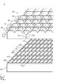
- FIG. 3 is an exploded perspective view showing the detailed configuration of the lens sheet and the pixel arrangement of the display panel.
- FIG. 4 is a plan view showing a detailed configuration of the pixel.
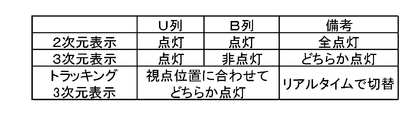
- FIG. 5 is a table summarizing the operation of the stereoscopic display device in each display mode.
- FIG. 6 is a plan view schematically showing a display mode of the display panel in the three-dimensional display mode.
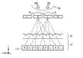
- FIG. 7 is a diagram schematically showing light emitted from the display panel.
- FIG. 1 is a schematic cross-sectional view showing a configuration of a stereoscopic display device according to the first embodiment of the present invention.
- FIG. 2 is a block diagram illustrating a functional configuration of the stereoscopic display device.
- FIG. 3 is
- FIG. 8 shows angular characteristics of luminance of the stereoscopic display device.
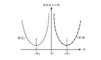
- FIG. 9 is a diagram illustrating angular characteristics of the left-eye crosstalk XT (L) and the right-eye crosstalk XT (R).
- FIG. 10 is a diagram for explaining the effect of two cylindrical lenses.
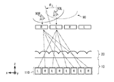
- FIG. 11 is a diagram for explaining the operation in the tracking three-dimensional display mode.
- FIG. 12 is a diagram for explaining the operation in the tracking three-dimensional display mode.
- FIG. 13 is a diagram for explaining the operation in the tracking three-dimensional display mode.
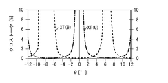
- FIG. 14 is a diagram showing the crosstalk angle characteristics of the stereoscopic display device.
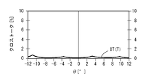
- FIG. 15 is a diagram illustrating the crosstalk angle characteristics when the stereoscopic display device is in the tracking three-dimensional display mode.
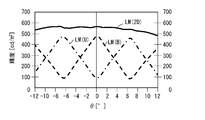
- FIG. 16 is a diagram illustrating the angular characteristics of the luminance of the stereoscopic display device.
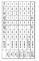
- FIG. 17 is a table showing the characteristics of the stereoscopic display device according to the embodiment of the present invention in comparison with other types of stereoscopic display devices.
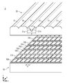
- FIG. 18 is an exploded perspective view showing the detailed configuration of the lens sheet of the stereoscopic display device according to the second embodiment of the present invention and the pixel arrangement of the display panel.
- FIG. 19 is an exploded perspective view showing a pixel arrangement of a lens sheet and a display panel of a stereoscopic display device according to the third embodiment of the present invention.
- FIG. 20 is a plan view showing a detailed configuration of a pixel of a display panel of a stereoscopic display device according to the third embodiment of the present invention.
- a stereoscopic display device includes a display panel that displays an image, and an image that is disposed so as to overlap the display panel and that is displayed on the display panel, horizontally to a right-eye image and a left-eye image.
- a lens sheet that is separated in a direction, a control unit that controls the display panel, and a position sensor that acquires position information of an observer and supplies the information to the control unit.
- the display panel includes first and second pixel columns that are alternately arranged in the vertical direction. The right-eye image emitted from the first pixel row and separated by the lens sheet and the right-eye image emitted from the second pixel row and separated by the lens sheet have horizontal positions. Different.
- the right-eye image emitted from the first pixel row and separated by the lens sheet and the right-eye image emitted from the second pixel row and separated by the lens sheet are positioned in the horizontal direction. Is different.
- the left-eye image emitted from the first pixel row and separated by the lens sheet differs from the left-eye image emitted from the second pixel row and separated by the lens sheet in the horizontal direction.
- the control unit selects one of the first pixel column and the second pixel column in accordance with the position information of the observer and displays an image.
- control unit selects one of the first pixel column and the second pixel column so that the position of the right eye image is close to the observer's right eye and the position of the left eye image is close to the observer's left eye.
- a stereoscopic image with low crosstalk can be obtained over a wide area.
- the first configuration preferably includes a plurality of cylindrical lenses extending in a straight direction, and each of the plurality of cylindrical lenses preferably has two lens centers that are separated by a predetermined distance in the horizontal direction (second Constitution).
- the light separated by the portion having one lens center of the cylindrical lens and the light separated by the portion having the other lens center overlap. Therefore, in each of the right-eye image and the left-eye image, high luminance can be obtained in a wider range, and crosstalk can be reduced. In other words, the region where the crosstalk is low can be widened.
- the low crosstalk region of the first pixel column and the low crosstalk region of the second pixel column can be widened. Therefore, the region between switching between the first pixel column and the second pixel column can be in a lower crosstalk state.
- each of the first pixel column and the second pixel column includes a plurality of pixels aligned in a horizontal direction at a predetermined pixel interval, and the pixels of the first pixel column and the first pixel column
- the pixels in the two-pixel array may be arranged so as to be shifted in the horizontal direction by half the pixel interval (third configuration).
- the lens sheet includes a first lens row that overlaps the first pixel row in plan view, and a second lens row that overlaps the second pixel row in plan view,
- Each of the first lens array and the second lens array includes a plurality of lenses aligned at a predetermined lens interval in the horizontal direction, and the lenses in the first lens array and the lenses in the second lens array are in the horizontal direction. It is good also as a structure shifted by 1/4 of the said lens space
- each of the first pixel column and the second pixel column includes a plurality of pixels aligned in a horizontal direction at a predetermined pixel interval, and an opening portion of a pixel of the first pixel column
- the pixel openings in the second pixel column may be arranged so as to be shifted in the horizontal direction by half the pixel interval (fifth configuration).
- the control unit has a two-dimensional display mode as a display mode.
- the first pixel column and the first display are independent of the position information.
- an image is displayed on both of the two pixel columns, and the same image is displayed on the adjacent first pixel column and the second pixel column (sixth configuration).
- the right-eye image and the left-eye image emitted from the first pixel row and separated by the lens sheet, and the right-eye image and the left-eye image emitted from the second pixel row and separated by the lens sheet Are different in horizontal position. Accordingly, both the first pixel column and the second pixel column are turned on, and the same image is displayed on the first pixel column and the second pixel column, so that they overlap and the luminance distribution is flattened. Can do. According to the above configuration, a two-dimensional image without moire can be obtained in the two-dimensional display mode.
- the display panel may be a liquid crystal display panel (seventh configuration).
- FIG. 1 is a schematic cross-sectional view showing a configuration of a stereoscopic display device 1 according to the first embodiment of the present invention.
- the stereoscopic display device 1 includes a display panel 10, a lens sheet 20, and an OCA (Optical Clear Adhesive) 30.
- the display panel 10 and the lens sheet 20 are disposed so as to overlap each other and are bonded together by the OCA 30.
- the display panel 10 includes a TFT (Thin Film Transistor) substrate 11, a CF (Color Filter) substrate 12, a liquid crystal layer 13, and polarizing plates 14 and 15.
- the display panel 10 controls the alignment of liquid crystal molecules in the liquid crystal layer 13 by controlling the TFT substrate 11 and the CF substrate 12.
- the display panel 10 is irradiated with light from a backlight unit (not shown).
- the display panel 10 displays an image by adjusting the light transmission amount for each pixel by the liquid crystal layer 13 and the polarizing plates 14 and 15.
- the lens sheet 20 separates the image displayed on the display panel 10 into a right-eye image and a left-eye image. A detailed configuration of the lens sheet 20 will be described later.
- a direction parallel to a line segment connecting the left eye 90L and the right eye 90R of the viewer 90 (the x direction in FIG. 1). ) Is called the horizontal direction.
- a direction (y direction in FIG. 1) perpendicular to the horizontal direction in the plane of the display panel 10 is referred to as a vertical direction.
- FIG. 2 is a block diagram showing a functional configuration of the stereoscopic display device 1.
- the stereoscopic display device 1 further includes a control unit 40, a position sensor 41, and an operation unit 42.
- the control unit 40 controls the display panel 10 to display an image on the display panel 10.
- the control unit 40 includes a signal conversion unit 401.
- the stereoscopic display device 1 has a plurality of display modes as will be described later.
- the signal conversion unit 401 converts the input signal Vin according to the display mode, and supplies the input signal Vin to the display driving unit 16 of the display panel 10 as the output signal Vout.
- the display driving unit 16 is, for example, a gate driver and a source driver.
- the position sensor 41 acquires the position information of the observer 90.
- the position sensor 41 is, for example, an eye tracking system that acquires an image with a camera and detects the eye position of the observer 90 by image processing.
- the position sensor 41 may be a head tracking system that detects the position of the head of the observer 90 using infrared rays.
- the position sensor 41 supplies the acquired position information to the control unit 40.
- the operation unit 42 receives an operation from the user and supplies the received information to the control unit 40.
- the user operates the operation unit 42 to switch the display mode of the stereoscopic display device 1.
- FIG. 3 is an exploded perspective view showing the detailed configuration of the lens sheet 20 and the pixel arrangement of the display panel 10.
- the lens sheet 20 includes a plurality of cylindrical lenses 21 extended along the vertical direction.
- the plurality of cylindrical lenses 21 are aligned at a lens interval P in the horizontal direction.
- Each of the plurality of cylindrical lenses 21 is a two-cylinder cylindrical lens having two lens centers 21a and 21b separated by a lens shift amount s in the horizontal direction. More specifically, each of the plurality of cylindrical lenses 21 has a shape in which two lenses having the same radius of curvature r are overlapped.
- the display panel 10 includes U columns (first pixel columns) 110 and B columns (second pixel columns) 120 that are alternately arranged in the vertical direction.
- the U column 110 includes a plurality of pixels 111 aligned at a pixel interval p in the horizontal direction.
- the B column 120 includes a plurality of pixels 121 aligned in the horizontal direction at a pixel interval p.
- the pixel 111 in the U column 110 and the pixel 121 in the B column 120 are arranged so as to be shifted by a half (p / 2) of the pixel interval p in the horizontal direction. Accordingly, the light emitted from the U row 110 and separated by the lens sheet 20 is different from the light emitted from the B row 120 and separated by the lens sheet 20 in the horizontal direction. More specifically, the right-eye image emitted from the U row 110 and separated by the lens sheet 20 and the right-eye image emitted from the B row 120 and separated by the lens sheet 20 have horizontal positions. Different. Similarly, the left-eye image emitted from the U row 110 and separated by the lens sheet 20 is different from the left-eye image emitted from the B row 120 and separated by the lens sheet 20 in the horizontal direction.
- lens interval P is approximately twice the pixel interval p.
- FIG. 4 is a plan view showing a detailed configuration of the pixels 111 and 121.
- the pixel 111 includes sub-pixels 111a, 111b, and 111c aligned in the vertical direction.
- the pixel 121 includes sub-pixels 121a, 121b, and 121c aligned in the vertical direction.
- the hatching in FIG. 4 schematically represents that the colors of the sub-pixels are different, and does not indicate a cross-sectional structure.
- the sub-pixels 111a and 121b transmit red light
- the sub-pixels 111b and 121b transmit green light
- the sub-pixels 111c and 121c transmit blue light. Areas other than these are shielded from light by the black matrix.
- the pixel 111 has openings in the sub-pixels 111a, 111b, and 111c
- the pixel 121 has openings in the sub-pixels 121a, 121b, and 121c.
- the configuration of the stereoscopic display device 1 has been described above. Next, the operation of the stereoscopic display device 1 will be described.
- FIG. 5 is a table summarizing the operation of the stereoscopic display device 1 in each display mode.
- the stereoscopic display device 1 has a two-dimensional display mode, a three-dimensional display mode, and a tracking three-dimensional display mode as display modes.
- the control unit 40 lights both the U row 110 and the B row 120 in the two-dimensional display mode.
- the control unit 40 lights one of the U row 110 and the B row 120.
- the control unit 40 lights one of the U row 110 and the B row 120 based on the position information supplied from the position sensor 41.
- FIG. 6 is a plan view schematically showing a display mode of the display panel 10 in the three-dimensional display mode.
- the control unit 40 lights up the U row 110 and turns off the B row 120.
- the control unit 40 causes the pixel 111 in the U row 110 to alternately display pixel data (R) constituting the right eye image and pixel data (L) constituting the left eye image.
- FIG. 7 is a diagram schematically showing light emitted from the display panel 10.
- the image displayed on the display panel 10 is separated into a right-eye image and a left-eye image by the lens sheet 20 in the horizontal direction.
- the observer 90 observes the stereoscopic display device 1 at an appropriate position, the right eye image is reflected in the right eye 90R, and the left eye image is reflected in the left eye 90L. Accordingly, the observer 90 recognizes the image displayed on the display panel 10 as a stereoscopic image.
- FIG 7 shows the distribution of luminance A R luminance A L and the right-eye image of the left eye image is shown schematically by the respective broken lines and one-dot chain line.
- the maximum brightness A L of the left-eye image at the position of the left eye 90L, the luminance A R of the right eye image is the largest at the position of the right eye 90R.
- FIG. 8 is used to quantitatively define the crosstalk.
- FIG. 8 shows the angular characteristics of the luminance of the stereoscopic display device 1.
- the luminance AL is a luminance observed at an angle ⁇ ⁇ 0 when the right-eye image is displayed in black and the left-eye image is displayed in white.
- Luminance B R in the same screen, a luminance observed at an angle theta> 0.
- the luminance AR is a luminance observed at an angle ⁇ ⁇ 0 when the right-eye image is displayed in white and the right-eye image is displayed in black.
- the luminance BL is the luminance observed at an angle ⁇ > 0 on the same screen.
- the luminance CL is a luminance observed at an angle ⁇ ⁇ 0 when both the right-eye image and the left-eye image are displayed in black.
- Luminance C R is the same screen, a luminance observed at an angle theta> 0.
- FIG. 9 is a diagram illustrating angular characteristics of the left-eye crosstalk XT (L) and the right-eye crosstalk XT (R).
- Left-eye crosstalk XT (L) takes a minimum value at the angle - [theta] 0, increases as deviated from the angle - [theta] 0.
- the right-eye crosstalk XT (R) is at an angle + theta 0 takes a minimum value, increases as deviated from the angle + theta 0.
- FIG. 10 is a diagram for explaining the effect of the two cylindrical lenses 21.
- each of the plurality of cylindrical lenses 21 has two lens centers 21a and 21b. According to this configuration, since the lens center 21a and the lens center 21b can be focused on the respective positions, the left and right image separation characteristics are improved. Thereby, in each of the right-eye image and the left-eye image, more luminance can be obtained and crosstalk can be reduced. In other words, the region where the crosstalk is low can be widened.
- Tracking 3D display mode In the tracking three-dimensional display mode, the control unit 40 lights one of the U row 110 and the B row 120 based on the position information supplied from the position sensor 41.
- the operation in the tracking three-dimensional display mode will be described with reference to FIGS.
- FIG. 11 shows a state where the observer 90 has moved to an area where crosstalk is high.
- the control unit 40 lights up the U row 110 and turns off the B row 120.
- the control unit 40 causes the U column 110 to alternately display the pixel data constituting the right eye image and the pixel data constituting the left eye image.
- the control unit 40 sets the U column 110 and the B column 120. Reverse the lighting state. That is, as shown in FIG. 12, the control unit 40 lights the B row 120 and turns off the U row 110. At this time, the control unit 40 causes the B column 120 to alternately display pixel data constituting the right-eye image and pixel data constituting the left-eye image.
- the horizontal position is different. More specifically, these images are shifted by half the distance between viewpoints in the horizontal direction. That is, the center position (the position with the highest luminance) of the right-eye image emitted from the B row 120 and separated by the lens sheet 20 is the center of the right-eye image emitted from the U row 110 and separated by the lens sheet 20. The position is intermediate between the position and the center position of the left-eye image.
- the center position of the left-eye image that is emitted from the B row 120 and separated by the lens sheet 20 is the center position of the right-eye image that is emitted from the U row 110 and separated by the lens sheet 20. It is in the middle of the center position.
- the region with high crosstalk is a region with low crosstalk when the B row 120 is turned on. Accordingly, in FIG. 12, the observer 90 is in a region where crosstalk is low.
- control unit 40 turns on one of the U row 110 and the B row 120 in which the crosstalk is low, according to the position of the observer 90. As a result, crosstalk can be reduced over a wide area.
- FIG. 13 shows a state where the observer 90 has moved further in the same direction from the state of FIG.
- the control unit 40 sets the U column 110 and the B column 120.
- the lighting state is reversed again. That is, as shown in FIG. 13, the control unit 40 lights up the U row 110 and turns off the B row 120.
- the control unit 40 causes the U column 110 to alternately display the pixel data constituting the right-eye image and the pixel data constituting the left-eye image.
- control unit 40 reverses the order of the pixel data constituting the right-eye image and the pixel data constituting the left-eye image from the state of FIG. 11 (left-right image swap). Accordingly, it is possible to avoid a reverse viewing state (a state in which the image for the left eye appears in the right eye 90R and the image for the right eye appears in the left eye 90L).
- the control unit 40 moves the U column 110, the B column 120, the U column 110 (left and right image swap), the B column 120 (left and right image swap), and the U column. 110, B column 120, and so on.
- the control unit 40 lights both the U row 110 and the B row 120 in the two-dimensional display mode. At this time, the control unit 40 displays the same pixel data on the adjacent pixels 111 in the U row 110. Similarly, the same pixel data is displayed on the adjacent pixels 121 in the B row 120. As a result, the right-eye image and the left-eye image become the same image. That is, the same image appears in the right eye 90R and the left eye 90L. Thus, the observer 90 recognizes the image displayed on the display panel 10 as a planar image.
- the control unit 40 further displays the same image in the adjacent U row 110 and B row 120 in the two-dimensional display mode.
- the light emitted from the U row 110 and separated by the lens sheet 20 and the light emitted from the B row 120 and separated by the lens sheet 20 are only half the distance between viewpoints in the horizontal direction. Shift. Therefore, the region where the luminance of the U column 110 is low is a region where the luminance of the B column 120 is high. Therefore, when both the U row 110 and the B row 120 are turned on and the same image is displayed on the adjacent U row 110 and the B row 120, they are overlapped to obtain a flat luminance distribution. As a result, a two-dimensional image without moire can be obtained.
- FIG. 14 and 15 are diagrams showing the crosstalk angle characteristics of the stereoscopic display device 1.
- XT (U) is the crosstalk angle characteristic when only the U row 110 is turned on
- XT (B) is the crosstalk angle characteristic when only the B row 120 is turned on.
- XT (U) and XT (B) have a shape shifted by a half cycle.
- the control unit 40 turns on one of the U column 110 and the B column 120 that has lower crosstalk, depending on the position of the observer 90. Therefore, the angular characteristic of the crosstalk XT (T) in the tracking three-dimensional display mode is as shown in FIG. In the tracking three-dimensional display mode, as shown in FIG. 15, crosstalk can be lowered over a wide area.
- the stereoscopic display device 1 performs tracking by switching display images on the display panel 10. Therefore, the stereoscopic display device 1 can perform tracking at a higher speed than the barrier division method described later.
- the stereoscopic display device 1 due to the effect of the two cylindrical lenses 21 having the two lens centers 21a and 21b, the U column 110 has a low crosstalk region and the B column 120 has a low crosstalk region. And are getting wider. By combining with tracking, the crosstalk can be reduced over the entire angular range.
- the stereoscopic display device 1 includes the two cylindrical lenses 21.
- the stereoscopic display device 1 may be provided with a cylindrical lens having one lens center instead of the two cylindrical lenses 21.
- FIG. 16 is a diagram showing the angular characteristics of the luminance of the same stereoscopic display device 1.
- LM (U) indicates the angular characteristic of the luminance when only the U row 110 is turned on
- LM (B) indicates the angular characteristic of the luminance when only the B row 120 is turned on
- LM (2D) Indicates the angular characteristics of luminance when both the U row 110 and the B row 120 are lit.
- LM (U) and LM (B) have a shape shifted by a half cycle. Since the LM (2D) in which both the U row 110 and the B row 120 are lit is an overlap of these, a flat angle characteristic can be obtained. As a result, in the two-dimensional display mode, a two-dimensional image without moire is obtained.
- FIG. 17 is a table showing the characteristics of the stereoscopic display device 1 according to this embodiment in comparison with stereoscopic display devices according to other methods.
- the column “trackability” describes whether the response speed at the time of tracking is sufficient.
- the “2D quality” column the image quality in the 2D display mode is described.
- the resolution in the two-dimensional display mode is a fraction of the resolution of the display panel.
- the “2D luminance” column the percentage of the luminance of the display panel in the luminance in the two-dimensional display mode is described.
- the “3D resolution” column the resolution in the 3D display mode is described as a fraction of the resolution of the display panel.
- 3D luminance the percentage of the luminance of the display panel in the luminance in the three-dimensional display mode is described.
- the column of “3D quality (XT)” describes the image quality in the 3D display mode.
- the “XT region” column describes whether or not there is a region with high crosstalk.
- the “N viewpoint (fixed lens)” method is a method of interpolating between two viewpoints by making viewpoints into multiple viewpoints.
- the resolution is 1 / N in both the two-dimensional display mode and the three-dimensional display mode.
- the image quality in the 3D display mode is poor.
- the “N viewpoint (SW-LCD)” system and the “N viewpoint (fixed barrier)” system are systems in which an image is separated into N viewpoints by a barrier.
- the luminance is 100 / N% due to the barrier.
- the “N viewpoint (SW-LCD)” method a two-dimensional display mode and a three-dimensional display mode are switched by a switch liquid crystal panel. Therefore, the brightness and resolution in the two-dimensional display mode can be set to 100%. However, the luminance and resolution in the three-dimensional display mode remain 1 / N.
- the “left and right image SWAP (SW-LCD)” method and the “left and right image SWAP (fixed lens)” method are methods for switching the right eye image and the left eye image by tracking the position of the observer. According to this method, a reverse viewing state can be avoided. However, there are always areas with high crosstalk. In the “left and right image SWAP (SW-LCD)” method, since the images are separated by the barrier, the luminance is halved in the three-dimensional display mode. In the “left and right image SWAP (fixed lens)” method, moire occurs because the images continue to be separated even in the two-dimensional display mode. For this reason, the image quality in the two-dimensional display mode is poor.
- the “barrier division (SW-LCD)” method is a method in which the liquid crystal molecules of the switch liquid crystal panel are finely controlled to change the position of the barrier according to the position of the observer. As a result, an area with high crosstalk can be eliminated. However, since the liquid crystal is driven to change the position of the barrier, the response speed is not sufficient. Further, since the images are separated by the barrier, the luminance is halved in the three-dimensional display mode.
- crosstalk in the tracking three-dimensional display mode, crosstalk can be reduced over a wide area.
- the tracking response speed is also sufficient.
- a two-dimensional image with little moire can be obtained.
- a luminance of 80% of the luminance of the display panel 10 can be obtained.
- the stereoscopic display device 1 is emitted from the U row 110 and separated by the lens sheet 20, and the right eye image and the left eye image are separated from the B row 120 and separated by the lens sheet 20. It is preferable that the right-eye image and the left-eye image are each designed to be shifted by half of the inter-viewpoint distance. That is, the stereoscopic display device 1 is preferably designed so that LM (U) and LM (B) are shifted by a half cycle, as shown in FIG. However, the right-eye image and the left-eye image that are emitted from the U row 110 and separated by the lens sheet 20 and the right-eye image and the left-eye image that are emitted from the B row 120 and separated by the lens sheet 20 are horizontal. If the directional positions are different, a certain effect can be obtained.
- the stereoscopic display device 2 includes a display panel 50 instead of the display panel 10 of the stereoscopic display device 1.
- the stereoscopic display device 2 further includes a lens sheet 60 instead of the lens sheet 20 of the stereoscopic display device 1.
- FIG. 18 is an exploded perspective view showing the detailed configuration of the lens sheet 60 and the pixel arrangement of the display panel 50.
- the display panel 50 is different in pixel arrangement from the display panel 10.
- the pixel 111 in the U column 110 and the pixel 121 in the B column 120 are aligned in the horizontal direction. That is, the pixel arrangement of the display panel 50 is a matrix pixel arrangement.
- the lens sheet 60 includes a first lens row 61 that overlaps the U row 110 in plan view and a second lens row 62 that overlaps the B row 120 in plan view. That is, the light emitted from the U row 110 is separated by the first lens row 61, and the light emitted from the B row 120 is separated by the second lens row 62.
- Each of the first lens array 61 and the second lens array 62 includes a plurality of cylindrical lenses 21 aligned at a predetermined lens interval P in the horizontal direction.
- the first lens array 61 and the second lens array 62 are arranged so as to be shifted by a quarter of the lens interval P in the horizontal direction.
- the right-eye image and the left-eye image that are emitted from the U row 110 and separated by the lens sheet 60, and the right-eye image and the left-eye image that are emitted from the B row 120 and separated by the lens sheet 60 are:
- the horizontal position is different.
- these images are shifted by a half of the distance between viewpoints in the horizontal direction, as in the first embodiment.
- one of the U row 110 and the B row 120 is turned on according to the position of the observer 90. As a result, crosstalk can be reduced over a wide area.
- the pixel arrangement of the display panel 50 of the stereoscopic display device 2 is a commonly used matrix pixel arrangement. Therefore, compared with the display panel 10 of the stereoscopic display device 1, it is excellent in mass productivity.
- the stereoscopic display device 3 includes a display panel 70 instead of the display panel 10 of the stereoscopic display device 1.
- FIG. 19 is an exploded perspective view showing the pixel arrangement of the lens sheet 20 and the display panel 70.
- the display panel 70 includes a U column 710 instead of the U column 110 of the display panel 10, and includes a B column 720 instead of the B column 120.
- the U column 710 includes a plurality of pixels 711 aligned at a pixel interval p in the horizontal direction.
- the B column 720 includes a plurality of pixels 721 aligned at a pixel interval p in the horizontal direction.
- the pixel 711 in the U column 710 and the pixel 721 in the B column 720 are aligned in the horizontal direction. That is, the pixel arrangement of the display panel 50 is a matrix pixel arrangement.
- FIG. 20 is a plan view showing a detailed configuration of the pixels 711 and 721.
- the pixel 711 includes sub-pixels 711a, 711b, and 711c aligned in the vertical direction.
- the pixel 721 includes sub-pixels 721a, 721b, and 721c aligned in the vertical direction. Note that hatching in FIG. 20 schematically represents that the colors of the sub-pixels are different, and does not indicate a cross-sectional structure.
- the subpixels 711a and 721b transmit red light
- the subpixels 711b and 721b transmit green light
- the subpixels 711c and 721c transmit blue light. Areas other than these are shielded from light by the black matrix.
- the pixel 711 has openings in the sub-pixels 711a, 711b, and 711c
- the pixel 721 has openings in the sub-pixels 721a, 721b, and 721c.
- the sub-pixels 711a, 711b, and 711c and the sub-pixels 721a, 721b, and 721c are arranged so as to be shifted by a half (p / 2) of the pixel interval p in the horizontal direction. That is, the opening of the pixel 711 in the U column 710 and the opening of the pixel 721 in the B column 720 are arranged so as to be shifted by a half (p / 2) of the pixel interval p in the horizontal direction.
- the right-eye image and the left-eye image that are emitted from the U row 710 and separated by the lens sheet 20 are:
- the horizontal position is different.
- these images are shifted by a half of the distance between viewpoints in the horizontal direction, as in the first embodiment.
- one of the U row 710 and the B row 720 is turned on according to the position of the observer 90. As a result, crosstalk can be reduced over a wide area.
- the pixel arrangement of the display panel 70 of the stereoscopic display device 3 is a matrix arrangement that is often used, and it is only necessary to change the configuration of the color filter. Therefore, compared with the display panel 10 of the stereoscopic display device 1, it is excellent in mass productivity.
- liquid crystal display panel As the display panel has been described.
- a plasma display panel or an organic EL (ElectroLuminescence) panel may be used instead of the liquid crystal display panel.
- the present invention can be used industrially as a stereoscopic display device.
Landscapes
- Physics & Mathematics (AREA)
- Engineering & Computer Science (AREA)
- Multimedia (AREA)
- Signal Processing (AREA)
- General Physics & Mathematics (AREA)
- Optics & Photonics (AREA)
- Geometry (AREA)
- Testing, Inspecting, Measuring Of Stereoscopic Televisions And Televisions (AREA)
Abstract
広い領域にわたって、クロストークの少ない良好な立体画像が得られる立体表示装置を提供する。立体表示装置(1)は、画像を表示する表示パネル(10)と、前記表示パネル(10)に重ねて配置され、前記表示パネル(10)に表示される画像を、右目用画像と左目用画像とに水平方向に分離するレンズシート(20)と、前記表示パネル(10)を制御する制御部と、観察者の位置情報を取得し、前記制御部へ供給する位置センサとを備える。前記表示パネル(10)は、垂直方向に交互に配置される第1画素列(110)および第2画素列(120)を含む。前記制御部は、前記位置情報に応じて、前記第1画素列(110)および前記第2画素列(120)の一方に、前記右目用画像を構成する画素データと前記左目用画像を構成する画素データとを水平方向に交互に表示させる。
Description
本発明は、裸眼立体表示装置に関する。
裸眼で観賞できる立体表示装置には、大別して視差バリア方式とレンチキュラレンズ方式とが知られている。これらの立体表示装置は、バリアまたはレンズによって光を分離して、左右の目に異なる画像を映すことで、観察者に立体感を与える。近年、市場に出ている裸眼立体表示装置は2視点の視差バリア方式とレンチキュラレンズ方式が主流となっている。
このような2視点の立体表示装置は、設定された領域では良好な立体表示が得られるが、観察者が頭を動かすと、右目に映るべき画像と左目に映るべき画像とが混ざって二重に映る、クロストーク(crosstalk)と呼ばれる現象や、右目に映るべき画像が左目に映ってしまう、いわゆる逆視状態が発生する領域が存在する。そのため、観察者は、限られた領域からしか立体画像を観察することができない。この課題に対して多視点化技術や、観察者の頭の位置を検出し、その位置に合わせて画像を表示させるトラッキング技術が提案されているが、2視点の立体表示性能を維持しながら、広い角度範囲で立体画像を観察できる立体表示装置は存在しない。
特許第2953433号公報に記載された立体表示装置は、表示装置と、視差画像分離手段とを有する。表示装置は、複数の右目用画素が特定の画素ピッチで水平方向に一直線上に並べられた第1の画素列と、複数の左目用画素が特定の画素ピッチで水平方向に一直線上に並べられた第2の画素列とを有する。第1の画素列と第2の画素列とは、右目用画素と左目用画素とが画素ピッチの1/2だけ水平方向にずれるように、垂直方向に交互に並べられる。
特許第2953433号公報に記載された立体表示装置は、画素の開口率を高くするほど、立体画像を観察できる領域が狭くなるという問題がある。
本発明の目的は、広い領域にわたって、クロストークの低く、かつ2次元表示時の表示品位を損なうことがない立体画像が得られる立体表示装置を提供することである。
ここに開示する立体表示装置は、画像を表示する表示パネルと、前記表示パネルに重ねて配置され、前記表示パネルに表示される画像を、右目用画像と左目用画像とに水平方向に分離するレンズシートと、前記表示パネルを制御する制御部と、観察者の位置情報を取得し、前記制御部へ供給する位置センサとを備える。前記表示パネルは、垂直方向に交互に配置される第1画素列および第2画素列を含む。前記第1画素列から出射して前記レンズシートによって分離された前記右目用画像と、前記第2画素列から出射して前記レンズシートによって分離された前記右目用画像とは、水平方向の位置が異なる。前記第1画素列から出射して前記レンズシートによって分離された前記左目用画像と、前記第2画素列から出射して前記レンズシートによって分離された前記左目用画像とは、水平方向の位置が異なる。前記制御部は、前記位置情報に応じて、前記第1画素列および前記第2画素列の一方に、前記右目用画像を構成する画素データと前記左目用画像を構成する画素データとを水平方向に交互に表示させる。
本発明によれば、広い領域にわたって、クロストークの低い立体画像が得られる立体表示装置が得られる。
本発明の一実施形態にかかる立体表示装置は、画像を表示する表示パネルと、前記表示パネルに重ねて配置され、前記表示パネルに表示される画像を、右目用画像と左目用画像とに水平方向に分離するレンズシートと、前記表示パネルを制御する制御部と、観察者の位置情報を取得し、前記制御部へ供給する位置センサとを備える。前記表示パネルは、垂直方向に交互に配置される第1画素列および第2画素列を含む。前記第1画素列から出射して前記レンズシートによって分離された前記右目用画像と、前記第2画素列から出射して前記レンズシートによって分離された前記右目用画像とは、水平方向の位置が異なる。前記第1画素列から出射して前記レンズシートによって分離された前記左目用画像と、前記第2画素列から出射して前記レンズシートによって分離された前記左目用画像とは、水平方向の位置が異なる。前記制御部は、前記位置情報に応じて、前記第1画素列および前記第2画素列の一方に、前記右目用画像を構成する画素データと前記左目用画像を構成する画素データとを水平方向に交互に表示させる(第1の構成)。
上記の構成によれば、第1画素列から出射してレンズシートによって分離された右目用画像と、第2画素列から出射してレンズシートによって分離された右目用画像とは、水平方向の位置が異なる。同様に、第1画素列から出射してレンズシートによって分離された左目用画像と、第2画素列から出射してレンズシートによって分離された左目用画像とは、水平方向の位置が異なる。制御部は、観察者の位置情報に応じて、第1画素列および第2画素列の一方を選択して画像を表示させる。すなわち、制御部は、右目用画像の位置が観察者の右目に近く、左目用画像の位置が観察者の左目の近くなるように、第1画素列および第2画素列の一方を選択する。これによって、広い領域にわたって、クロストークの低い立体画像が得られる
上記第1の構成において、直方向に延伸した複数のシリンドリカルレンズを含み、前記複数のシリンドリカルレンズのそれぞれは、水平方向に所定の間隔だけ離れた2つのレンズ中心を有することが好ましい(第2の構成)。
上記の構成によれば、シリンドリカルレンズの一方のレンズ中心を持つ部分によって分離される光と、他方のレンズ中心を持つ部分によって分離される光とが重なり合う。そのため、右目用画像および左目用画像のそれぞれにおいて、より広い範囲で高い輝度が得られ、クロストークを低減させることができる。換言すれば、クロストークが低い領域を広くすることができる。
これによって、第1画素列のクロストークの低い領域と、第2画素列のクロストークの低い領域とを、それぞれ広くすることができる。そのため、第1画素列と第2画素列とを切り替える間の領域を、よりクロストークの低い状態にすることができる。
上記第1または第2の構成において、前記第1画素列および前記第2画素列はそれぞれ、水平方向に所定の画素間隔で整列した複数の画素を含み、前記第1画素列の画素と前記第2画素列の画素とは、水平方向に前記画素間隔の半分だけずらして配置される構成としても良い(第3の構成)。
上記第1または第2の構成において、前記レンズシートは、平面視において前記第1画素列に重なる第1レンズ列と、平面視において前記第2画素列に重なる第2レンズ列とを含み、前記第1レンズ列および前記第2レンズ列はそれぞれ、水平方向に所定のレンズ間隔で整列した複数のレンズを含み、前記第1レンズ列のレンズと前記第2レンズ列のレンズとは、水平方向に前記レンズ間隔の1/4だけずらして配置される構成としても良い(第4の構成)。
上記第1または第2の構成において、前記第1画素列および前記第2画素列はそれぞれ、水平方向に所定の画素間隔で整列した複数の画素を含み、前記第1画素列の画素の開口部と前記第2画素列の画素の開口部とは、水平方向に前記画素間隔の半分だけずらして配置される構成としても良い(第5の構成)。
上記第1~第5のいずれかの構成において、前記制御部は、表示モードとして2次元表示モードを有し、前記2次元表示モードでは、前記位置情報によらず前記第1画素列および前記第2画素列の両方に画像を表示させ、隣接する前記第1画素列と前記第2画素列とに同じ画像を表示させることが好ましい(第6の構成)。
上述のように、第1画素列から出射してレンズシートによって分離された右目用画像および左目用画像と、第2画素列から出射してレンズシートによって分離された右目用画像および左目用画像とは、水平方向の位置が異なる。したがって、第1画素列と第2画素列とを両方点灯させ、さらに第1画素列と第2画素列とに同じ画像を表示させることによって、これらが重なりあって、輝度分布をフラットにすることができる。上記の構成によれば、2次元表示モードにおいて、モアレの無い2次元画像を得ることができる。
上記第1~第6のいずれかの構成において、前記表示パネルは、液晶表示パネルであっても良い(第7の構成)。
[実施の形態]
以下、図面を参照し、本発明の実施の形態を詳しく説明する。図中同一または相当部分には同一符号を付してその説明は繰り返さない。なお、説明を分かりやすくするために、以下で参照する図面においては、構成が簡略化または模式化して示されたり、一部の構成部材が省略されたりしている。また、各図に示された構成部材間の寸法比は、必ずしも実際の寸法比を示すものではない。
以下、図面を参照し、本発明の実施の形態を詳しく説明する。図中同一または相当部分には同一符号を付してその説明は繰り返さない。なお、説明を分かりやすくするために、以下で参照する図面においては、構成が簡略化または模式化して示されたり、一部の構成部材が省略されたりしている。また、各図に示された構成部材間の寸法比は、必ずしも実際の寸法比を示すものではない。
[第1の実施形態]
図1は、本発明の第1の実施形態にかかる立体表示装置1の構成を示す模式的断面図である。立体表示装置1は、表示パネル10と、レンズシート20と、OCA(Optical Clear Adhesive)30と備えている。表示パネル10とレンズシート20とは重ねて配置され、OCA30によって貼り合わされている。
図1は、本発明の第1の実施形態にかかる立体表示装置1の構成を示す模式的断面図である。立体表示装置1は、表示パネル10と、レンズシート20と、OCA(Optical Clear Adhesive)30と備えている。表示パネル10とレンズシート20とは重ねて配置され、OCA30によって貼り合わされている。
表示パネル10は、TFT(Thin Film Transistor)基板11と、CF(Color Filter)基板12と、液晶層13と、偏光板14および15とを備えている。表示パネル10は、TFT基板11およびCF基板12を制御して、液晶層13の液晶分子の配向を操作する。表示パネル10には、図示しないバックライトユニットから光が照射される。表示パネル10は、液晶層13ならびに偏光板14および15によって、画素ごとに光の透過量を調整して、画像を表示する。
レンズシート20は、表示パネル10に表示される画像を、右目用画像と左目用画像とに分離する。レンズシート20の詳しい構成は後述する。
以下、図1に示すように、観察者90と立体表示装置1とが真っ直ぐに向かい合ったときの、観察者90の左目90Lと右目90Rとを結ぶ線分に平行な方向(図1のx方向)を、水平方向と呼ぶ。また、表示パネル10の面内において水平方向と直交する方向(図1のy方向)を垂直方向と呼ぶ。
図2は、立体表示装置1の機能的構成を示すブロック図である。立体表示装置1は、制御部40と、位置センサ41と、操作部42とをさらに備えている。
制御部40は、表示パネル10を制御して、表示パネル10に画像を表示させる。制御部40は、信号変換部401を含んでいる。
立体表示装置1は、後述するように、複数の表示モードを有している。信号変換部401は、入力信号Vinを表示モードに応じて変換し、出力信号Voutとして表示パネル10の表示駆動部16に供給する。表示駆動部16は、例えばゲートドライバおよびソースドライバである。
位置センサ41は、観察者90の位置情報を取得する。位置センサ41は例えば、カメラによって画像を取得し、画像処理によって観察者90の目の位置を検出するアイトラッキングシステムである。位置センサ41はあるいは、赤外線によって観察者90の頭の位置を検出するヘッドトラッキングシステムであっても良い。位置センサ41は、取得した位置情報を、制御部40に供給する。
操作部42は、ユーザからの操作を受け付け、受け付けた情報を制御部40に供給する。ユーザは、操作部42を操作して、立体表示装置1の表示モードを切り替える。
図3は、レンズシート20の詳しい構成、および表示パネル10の画素配置を示す分解斜視図である。
図3に示すように、レンズシート20は、垂直方向に沿って延伸した複数のシリンドリカルレンズ21を含んでいる。複数のシリンドリカルレンズ21は、水平方向にレンズ間隔Pで整列している。複数のシリンドリカルレンズ21のそれぞれは、水平方向にレンズシフト量sだけ離れた2つのレンズ中心21aおよび21bを有する、2山のシリンドリカルレンズである。より詳しくは、複数のシリンドリカルレンズ21のそれぞれは、同一の曲率半径rを持った2つのレンズが重なった形状を有している。
表示パネル10は、垂直方向に交互に配置された、U列(第1画素列)110と、B列(第2画素列)120とを含んでいる。U列110は、水平方向に画素間隔pで整列した複数の画素111を含んでいる。同様に、B列120は、水平方向に画素間隔pで整列した複数の画素121を含んでいる。
U列110の画素111とB列120の画素121とは、水平方向に画素間隔pの半分(p/2)だけずらして配置されている。これによって、U列110から出射してレンズシート20によって分離される光と、B列120から出射してレンズシート20によって分離される光とは、水平方向の位置が異なる。より具体的には、U列110から出射してレンズシート20によって分離される右目用画像と、B列120から出射してレンズシート20によって分離される右目用画像とは、水平方向の位置が異なる。同様に、U列110から出射してレンズシート20によって分離される左目用画像と、B列120から出射してレンズシート20によって分離される左目用画像とは、水平方向の位置が異なる。
なお、レンズ間隔Pは、画素間隔pの約2倍である。
図4は、画素111および121の詳しい構成を示す平面図である。画素111は、垂直方向に整列したサブ画素111a、111bおよび111cを含んでいる。画素121も同様に、垂直方向に整列したサブ画素121a、121bおよび121cを含んでいる。なお、図4中のハッチングは、各サブ画素の色が異なることを模式的に表現したものであって、断面構造を示すものではない。
例えば、サブ画素111aおよび121bは赤色の光を透過し、サブ画素111bおよび121bは緑色の光を透過し、サブ画素111cおよび121cは青色の光を透過する。これら以外の領域は、ブラックマトリクスによって遮光されている。換言すれば画素111は、サブ画素111a、111b、および111cに開口部を有し、画素121は、サブ画素121a、121b、および121cに開口部を有している。
以上、立体表示装置1の構成について説明した。次に、立体表示装置1の動作について説明する。
図5は、各表示モードにおける立体表示装置1の動作をまとめた表である。立体表示装置1は、表示モードとして、2次元表示モードと、3次元表示モードと、トラッキング3次元表示モードとを有する。図5に示すように、制御部40は、2次元表示モードでは、U列110およびB列120の両方を点灯させる。制御部40は、3次元表示モードでは、U列110およびB列120のいずれか一方を点灯させる。そして、制御部40は、トラッキング3次元表示モードでは、位置センサ41から供給される位置情報に基づいて、U列110およびB列120のいずれか一方を点灯させる。
[3次元表示モード]
制御部40は、3次元表示モードではU列110およびB列120のいずれか一方を点灯させる。図6は、3次元表示モードにおける表示パネル10の表示の態様を模式的に示した平面図である。図6では、制御部40は、U列110を点灯させ、B列120を非点灯にしている。制御部40は、U列110の画素111に、右目用画像を構成する画素データ(R)と左目用画像を構成する画素データ(L)とを交互に表示させている。
制御部40は、3次元表示モードではU列110およびB列120のいずれか一方を点灯させる。図6は、3次元表示モードにおける表示パネル10の表示の態様を模式的に示した平面図である。図6では、制御部40は、U列110を点灯させ、B列120を非点灯にしている。制御部40は、U列110の画素111に、右目用画像を構成する画素データ(R)と左目用画像を構成する画素データ(L)とを交互に表示させている。
図7は、表示パネル10から出射される光を模式的に示す図である。図7に示すように、レンズシート20によって、表示パネル10に表示された画像は、右目用画像と左目用画像とに水平方向に分離される。観察者90が適切な位置で立体表示装置1を観察すると、右目90Rには右目用画像が映り、左目90Lには左目用画像が映る。観察者90はこれによって、表示パネル10に表示される画像を、立体画像として認識する。
図7には、左目用画像の輝度ALおよび右目用画像の輝度ARの分布を、それぞれ破線および一点鎖線によって模式的に示している。図7では、左目90Lの位置において左目用画像の輝度ALが最大になり、右目90Rの位置において右目用画像の輝度ARが最大になっている。
この位置から観察者90が動くと、左目90Lの位置では、左目用画像の輝度ALが低下し、右目用画像の輝度ARが増加する。同様に、右目90Rの位置では、右目用画像の輝度ARが低下し、左目用画像の輝度ALが増加する。この結果、左目90Lに右目用画像が混入し、右目90Rに左目用画像が混入する。この現象はクロストークと呼ばれ、著しくなると立体感が損なわれるだけでなく、観察者90に不快感を与える原因となる。
図8を用いて、クロストークを定量的に定義する。図8は、立体表示装置1の輝度の角度特性である。輝度ALは、右目用画像を黒表示、左目用画像を白表示にしたとき、角度θ<0において観測される輝度である。輝度BRは、同じ画面において、角度θ>0において観測される輝度である。輝度ARは、右目用画像を白表示、右目用画像を黒表示にしたとき、角度θ<0において観測される輝度である。輝度BLは、同じ画面において、角度θ>0において観測される輝度である。輝度CLは、右目用画像および左目用画像の両方を黒表示にしたとき、角度θ<0において観測される輝度である。輝度CRは、同じ画面において、角度θ>0において観察される輝度である。
このとき、左目のクロストークXT(L)を、次の式で定義する。

同様に、右目のクロストークXT(R)を、次の式で定義する。

図9は、左目のクロストークXT(L)および右目のクロストークXT(R)の角度特性を示す図である。左目用クロストークXT(L)は、角度-θ0において極小値を取り、角度-θ0からずれるにしたがって大きくなる。同様に、右目用クロストークXT(R)は、角度+θ0において極小値を取り、角度+θ0からずれるにしたがって大きくなる。
図10は、2山のシリンドリカルレンズ21の効果を説明するための図である。既述のように、複数のシリンドリカルレンズ21のそれぞれは、2つのレンズ中心21aおよび21bを有する。この構成によれば、レンズ中心21aと、レンズ中心21bがそれぞれの位置に焦点を持たせることができるため、左右の画像分離特性が向上する。これにより右目用画像および左目用画像のそれぞれにおいて、より輝度が得られるとともに、クロストークを低減させることができる。換言すれば、クロストークが低い領域を広くすることができる。
[トラッキング3次元表示モード]
制御部40は、トラッキング3次元表示モードでは、位置センサ41から供給される位置情報に基づいて、U列110およびB列120のいずれか一方を点灯させる。以下、図11~図13を用いて、トラッキング3次元表示モードにおける動作について説明する。
制御部40は、トラッキング3次元表示モードでは、位置センサ41から供給される位置情報に基づいて、U列110およびB列120のいずれか一方を点灯させる。以下、図11~図13を用いて、トラッキング3次元表示モードにおける動作について説明する。
図11は、観察者90が、クロストークの高い領域に移動した状態を示している。図11では、制御部40は、U列110を点灯させ、B列120を非点灯にしている。制御部40は、U列110に、右目用画像を構成する画素データと左目用画像を構成する画素データとを交互に表示させている。
制御部40は、例えば、立体表示装置1の中心から観察者90を結ぶ線分と、表示パネル10の法線とのなす角度が所定値θ1以上になると、U列110およびB列120の点灯状態を反転させる。すなわち、制御部40は、図12に示すように、B列120を点灯させ、U列110を非点灯にする。制御部40はこのとき、B列120に、右目用画像を構成する画素データと左目用画像を構成する画素データとを交互に表示させる。
既述のように、U列110から出射してレンズシート20によって分離される右目用画像および左目用画像と、B列120から出射してレンズシート20によって分離される右目用画像および左目用画像とは、水平方向の位置が異なる。これらの画像は、より具体的には、水平方向に視点間距離の半分だけずれる。すなわち、B列120から出射してレンズシート20によって分離される右目用画像の中心位置(最も輝度が高い位置)は、U列110から出射してレンズシート20によって分離される右目用画像の中心位置と左目用画像の中心位置との中間になる。同様に、B列120から出射してレンズシート20によって分離される左目用画像の中心位置は、U列110から出射してレンズシート20によって分離される右目用画像の中心位置と左目用画像の中心位置との中間になる。
そのため、U列110を点灯させたときクロストークの高い領域は、B列120を点灯させたときはクロストークの低い領域となる。これによって、図12では、観察者90は、クロストークの低い領域にいることになる。
このように、制御部40は、観察者90の位置に応じて、U列110およびB列120のうち、クロストークが低くなる方を点灯させる。これによって、広い領域にわたってクロストークを低くすることができる。
図13は、観察者90が、図12の状態からさらに同じ方向に移動した状態を示している。制御部40は、例えば、立体表示装置1の中心から観察者90を結ぶ線分と、表示パネル10の法線とのなす角度が所定値θ2以上になると、U列110およびB列120の点灯状態を再び反転させる。すなわち、制御部40は、図13に示すように、U列110を点灯させ、B列120を非点灯にする。制御部40はこのとき、U列110に、右目用画像を構成する画素データと左目用画像を構成する画素データとを交互に表示させる。
制御部40はさらに、右目用画像を構成する画素データと左目用画像を構成する画素データとの順番を、図11の状態から反転させる(左右画像スワップ)。これによって、逆視状態(右目90Rに左目用画像が映り、左目90Lに右目用画像が映る状態)を避けることができる。
制御部40は、このように、観察者90の位置が一方向に移動する場合、U列110、B列120、U列110(左右画像スワップ)、B列120(左右画像スワップ)、U列110、B列120・・・という順番で表示させる。これによって、観察者90が移動した際にも、クロストークの発生を抑制することができ、広い領域にわたってクロストークの低い良好な立体画像が得られる。
[2次元表示モード]
制御部40は、2次元表示モードでは、U列110およびB列120の両方を点灯させる。制御部40はこのとき、U列110の隣接する画素111に同じ画素データを表示させる。同様に、B列120の隣接する画素121に同じ画素データを表示させる。これによって、右目用画像と左目用画像は同じ画像になる。すなわち、右目90Rと左目90Lとには、同じ画像が映る。観察者90はこれによって、表示パネル10に表示される画像を、平面画像として認識する。
制御部40は、2次元表示モードでは、U列110およびB列120の両方を点灯させる。制御部40はこのとき、U列110の隣接する画素111に同じ画素データを表示させる。同様に、B列120の隣接する画素121に同じ画素データを表示させる。これによって、右目用画像と左目用画像は同じ画像になる。すなわち、右目90Rと左目90Lとには、同じ画像が映る。観察者90はこれによって、表示パネル10に表示される画像を、平面画像として認識する。
制御部40はさらに、2次元表示モードでは、隣接するU列110とB列120とに同じ画像を表示させる。既述のように、U列110から出射してレンズシート20によって分離される光と、B列120から出射してレンズシート20によって分離される光とは、水平方向に視点間距離の半分だけずれる。そのため、U列110の輝度が低い領域は、B列120の輝度が高い領域となる。したがって、U列110とB列120とを両方点灯させ、さらに隣接するU列110とB列120とに同じ画像を表示させることによって、これらが重なり合って、フラットな輝度分布が得られる。これによって、モアレの無い2次元画像を得ることができる。
以上、立体表示装置1の動作について説明した。以下、具体的な構成例を示して、立体表示装置1の効果を説明する。
図14および図15は、立体表示装置1のクロストークの角度特性を示す図である。このデータは、パネルサイズ3.5インチ、画素間隔p=96μm、レンズ間隔P=191.82μm、曲率半径r=154μm、レンズシフト量s=38μmの立体表示装置1によって得られた。
図14中、XT(U)はU列110だけを点灯させたときのクロストークの角度特性であり、XT(B)はB列120だけを点灯させたときのクロストークの角度特性である。図14に示すように、XT(U)とXT(B)とは、半周期分ずれた形状を有している。
既述のように、制御部40は、トラッキング3次元表示モードでは、観察者90の位置に応じて、U列110およびB列120のうち、クロストークが低くなる方を点灯させる。したがって、トラッキング3次元表示モードにおけるクロストークXT(T)の角度特性は、図15に示すようになる。トラッキング3次元表示モードでは、図15に示すように、広い領域にわたって、クロストークを低くすることができる。
立体表示装置1は、トラッキングを、表示パネル10の表示画像の切り替えによって行う。そのため立体表示装置1は、後述するバリア分割方式と比較して、トラッキングを高速に行うことができる。
本実施形態にかかる立体表示装置1では、2つのレンズ中心21aおよび21bを有する2山のシリンドリカルレンズ21の効果によって、U列110のクロストークの低い領域と、B列120のクロストークの低い領域とが、それぞれ広くなっている。トラッキングと組み合わせることによって、全ての角度範囲にわたってクロストークの低い状態にすることができる。このように、立体表示装置1は、2山のシリンドリカルレンズ21を備えることが好ましい。しかし、立体表示装置1は、2山のシリンドリカルレンズ21に代えて、1つのレンズ中心を有するシリンドリカルレンズを備えたものであっても良い。
図16は、同じ立体表示装置1の輝度の角度特性を示す図である。図16中、LM(U)はU列110だけを点灯させたときの輝度の角度特性を、LM(B)はB列120だけを点灯させたときの輝度の角度特性を、LM(2D)はU列110およびB列120の両方を点灯させたときの輝度の角度特性を、それぞれ示している。
図16に示すように、LM(U)とLM(B)とは、半周期分ずれた形状を有している。U列110とB列120とを両方点灯させたLM(2D)はこれらの重ね合わせであるため、フラットな角度特性が得られる。これによって、2次元表示モードでは、モアレの無い2次元画像が得られる。
また、3次元表示モード(U列110およびB列120の一方を点灯)においても、2山のシリンドリカルレンズ21の効果により、2次元表示モード時の80%の輝度が得られている。
図17は、本実施形態にかかる立体表示装置1の特性を、他の方式による立体表示装置と比較して示した表である。「追随性」の欄には、トラッキング時の応答速度が十分であるかを記載している。「2D時品位」の欄には、2次元表示モード時の画質について記載している。「2D時解像度」の欄には、2次元表示モード時の解像度が、表示パネルの解像度の何分の1になるかを記載している。「2D時輝度」の欄には、2次元表示モード時の輝度が、表示パネルの輝度の何%になるかを記載している。「3D時解像度」の欄には、3次元表示モード時の解像度が、表示パネルの解像度の何分の1になるかを記載している。「3D時輝度」の欄には、3次元表示モード時の輝度が、表示パネルの輝度の何%になるかを記載している。「3D品位(XT)」の欄には、3次元表示モード時の画質について記載している。「XT領域」の欄には、クロストークの高い領域の有無について記載している。
「N視点(固定レンズ)」方式は、視点を多視点化することにより、2視点間を補間する方式である。この方式では、2次元表示モード時および3次元表示モード時の両方において、解像度が1/Nになる。また、3次元表示モード時の画質も悪い。
「N視点(SW-LCD)」方式および「N視点(固定バリア)」方式は、バリアによって画像をN視点に分離する方式である。この方式では、解像度が1/Nになるのに加えて、バリアによって輝度が100/N%になる。「N視点(SW-LCD)」方式では、スイッチ液晶パネルによって、2次元表示モードと3次元表示モードとを切り替える。そのため、2次元表示モード時の輝度および解像度を100%にすることができる。しかし、3次元表示モード時の輝度および解像度は1/Nのままである。
「左右画像SWAP(SW-LCD)」方式および「左右画像SWAP(固定レンズ)」方式は、観察者の位置をトラッキングして、右目用画像と左目用画像とを切り替える方式である。この方式によれば、逆視状態を避けることができる。しかし、クロストークの高い領域は必ず存在する。また、「左右画像SWAP(SW-LCD)」方式は、バリアによって画像を分離するため、3次元表示モードでは輝度が半分になる。「左右画像SWAP(固定レンズ)」方式は、2次元表示モード時にも画像が分離され続けるため、モアレが発生する。そのため、2次元表示モードにおける画質が悪い。
「バリア分割(SW-LCD)」方式は、スイッチ液晶パネルの液晶分子を細かく制御して、観察者の位置に応じてバリアの位置を変える方式である。これによって、クロストークの高い領域を無くすことができる。しかし、液晶を駆動してバリアの位置を変えるため、応答速度は十分ではない。また、バリアによって画像を分離するため、3次元表示モードでは輝度が半分になる。
本実施形態によれば、トラッキング3次元表示モードでは、広い領域にわたってクロストークを低くすることができる。トラッキングの応答速度も十分である。また、2次元表示モードでは、モアレの少ない2次元画像が得られる。さらに、3次元表示モードにおいても、表示パネル10の輝度の80%の輝度が得られる。
立体表示装置1は、本実施形態のように、U列110から出射してレンズシート20によって分離される右目用画像および左目用画像と、B列120から出射してレンズシート20によって分離される右目用画像および左目用画像とが、それぞれ視点間距離の半分だけずれるように設計されることが好ましい。すなわち、立体表示装置1は、図16に示すように、LM(U)とLM(B)とが、半周期分ずれるように設計されることが好ましい。しかし、U列110から出射してレンズシート20によって分離される右目用画像および左目用画像と、B列120から出射してレンズシート20によって分離される右目用画像および左目用画像とは、水平方向の位置が異なっていれば、一定の効果が得られる。
[第2の実施形態]
本発明の第2の実施形態にかかる立体表示装置2は、立体表示装置1の表示パネル10に代えて、表示パネル50を備えている。立体表示装置2はさらに、立体表示装置1のレンズシート20に代えて、レンズシート60を備えている。図18は、レンズシート60の詳しい構成、および表示パネル50の画素配置を示す分解斜視図である。
本発明の第2の実施形態にかかる立体表示装置2は、立体表示装置1の表示パネル10に代えて、表示パネル50を備えている。立体表示装置2はさらに、立体表示装置1のレンズシート20に代えて、レンズシート60を備えている。図18は、レンズシート60の詳しい構成、および表示パネル50の画素配置を示す分解斜視図である。
表示パネル50は、表示パネル10と比較して、画素配置が異なっている。表示パネル50では、U列110の画素111とB列120の画素121とは、水平方向の位置が揃っている。すなわち、表示パネル50の画素配置は、マトリクス状の画素配置である。
レンズシート60は、平面視においてU列110に重なる第1レンズ列61と、平面視においてB列120に重なる第2レンズ列62とを含んでいる。すなわち、U列110から出射する光は第1レンズ列61によって分離され、B列120から出射する光は第2レンズ列62によって分離される。第1レンズ列61および第2レンズ列62はそれぞれ、水平方向に所定のレンズ間隔Pで整列した複数のシリンドリカルレンズ21を含んでいる。
第1レンズ列61と第2レンズ列62とは、水平方向にレンズ間隔Pの1/4だけずらして配置されている。これによって、U列110から出射してレンズシート60によって分離される右目用画像および左目用画像と、B列120から出射してレンズシート60によって分離される右目用画像および左目用画像とは、水平方向の位置が異なる。
これらの画像は、より具体的には、第1の実施形態と同様に、水平方向に視点間距離の半分だけずれる。本実施形態においても、トラッキング3次元表示モードでは、観察者90の位置に応じてU列110およびB列120の一方を点灯させる。これによって、広い領域にわたってクロストークを低くすることができる。
立体表示装置2の表示パネル50の画素配置は、よく用いられるマトリクス状の画素配置である。したがって、立体表示装置1の表示パネル10と比較して、量産性に優れる。
[第3の実施形態]
本発明の第3の実施形態にかかる立体表示装置3は、立体表示装置1の表示パネル10に代えて、表示パネル70を備えている。図19は、レンズシート20、および表示パネル70の画素配置を示す分解斜視図である。
本発明の第3の実施形態にかかる立体表示装置3は、立体表示装置1の表示パネル10に代えて、表示パネル70を備えている。図19は、レンズシート20、および表示パネル70の画素配置を示す分解斜視図である。
表示パネル70は、表示パネル10のU列110に代えてU列710を含み、B列120に代えてB列720を含んでいる。U列710は、水平方向に画素間隔pで整列した複数の画素711を含んでいる。同様に、B列720は、水平方向に画素間隔pで整列した複数の画素721を含んでいる。
U列710の画素711とB列720の画素721とは、水平方向の位置が揃っている。すなわち、表示パネル50の画素配置は、マトリクス状の画素配置である。
図20は、画素711および721の詳しい構成を示す平面図である。画素711は、垂直方向に整列したサブ画素711a、711bおよび711cを含んでいる。画素721も同様に、垂直方向に整列したサブ画素721a、721bおよび721cを含んでいる。なお、図20中のハッチングは、各サブ画素の色が異なることを模式的に表現したものであって、断面構造を示すものではない。
例えば、サブ画素711aおよび721bは赤色の光を透過し、サブ画素711bおよび721bは緑色の光を透過し、サブ画素711cおよび721cは青色の光を透過する。これら以外の領域は、ブラックマトリクスによって遮光されている。換言すれば画素711は、サブ画素711a、711b、および711cに開口部を有し、画素721は、サブ画素721a、721b、および721cに開口部を有している。
サブ画素711a、711b、および711cと、サブ画素721a、721b、および721cとは、水平方向に画素間隔pの半分(p/2)だけずらして配置されている。すなわち、U列710の画素711の開口部とB列720の画素721の開口部とは、水平方向に画素間隔pの半分(p/2)だけずらして配置されている。これによって、U列710から出射してレンズシート20によって分離される右目用画像および左目用画像と、B列720から出射してレンズシート20によって分離される右目用画像および左目用画像とは、水平方向の位置が異なる。
これらの画像は、より具体的には、第1の実施形態と同様に、水平方向に視点間距離の半分だけずれる。本実施形態においても、トラッキング3次元表示モードでは、観察者90の位置に応じてU列710およびB列720の一方を点灯させる。これによって、広い領域にわたってクロストークを低くすることができる。
立体表示装置3の表示パネル70の画素配置は、よく用いられるマトリクス状の画素配置であり、カラーフィルタの構成を変更するだけで良い。したがって、立体表示装置1の表示パネル10と比較して、量産性に優れる。
[その他の実施形態]
以上、本発明についての実施形態を説明したが、本発明は上述の各実施形態のみに限定されず、発明の範囲内で種々の変更が可能である。また、各実施形態は、適宜組み合わせて実施することが可能である。
以上、本発明についての実施形態を説明したが、本発明は上述の各実施形態のみに限定されず、発明の範囲内で種々の変更が可能である。また、各実施形態は、適宜組み合わせて実施することが可能である。
上述の各実施形態では、表示パネルとして液晶表示パネルを用いた例を説明した。しかし、液晶表示パネルに代えて、プラズマ表示パネルや、有機EL(ElectroLuminescence)パネルを用いても良い。
本発明は、立体表示装置として産業上の利用が可能である。
Claims (7)
- 画像を表示する表示パネルと、
前記表示パネルに重ねて配置され、前記表示パネルに表示される画像を、右目用画像と左目用画像とに水平方向に分離するレンズシートと、
前記表示パネルを制御する制御部と、
観察者の位置情報を取得し、前記制御部へ供給する位置センサとを備え、
前記表示パネルは、垂直方向に交互に配置される第1画素列および第2画素列を含み、
前記第1画素列から出射して前記レンズシートによって分離された前記右目用画像と、前記第2画素列から出射して前記レンズシートによって分離された前記右目用画像とは、水平方向の位置が異なり、
前記第1画素列から出射して前記レンズシートによって分離された前記左目用画像と、前記第2画素列から出射して前記レンズシートによって分離された前記左目用画像とは、水平方向の位置が異なり、
前記制御部は、前記位置情報に応じて、前記第1画素列および前記第2画素列の一方に、前記右目用画像を構成する画素データと前記左目用画像を構成する画素データとを水平方向に交互に表示させる、立体表示装置。 - 前記レンズシートは、垂直方向に延伸した複数のシリンドリカルレンズを含み、
前記複数のシリンドリカルレンズのそれぞれは、水平方向に所定の間隔だけ離れた2つのレンズ中心を有する、請求項1に記載の立体表示装置。 - 前記第1画素列および前記第2画素列はそれぞれ、水平方向に所定の画素間隔で整列した複数の画素を含み、
前記第1画素列の画素と前記第2画素列の画素とは、水平方向に前記画素間隔の半分だけずらして配置される、請求項1または2に記載の立体表示装置。 - 前記レンズシートは、平面視において前記第1画素列に重なる第1レンズ列と、平面視において前記第2画素列に重なる第2レンズ列とを含み、
前記第1レンズ列および前記第2レンズ列はそれぞれ、水平方向に所定のレンズ間隔で整列した複数のレンズを含み、
前記第1レンズ列のレンズと前記第2レンズ列のレンズとは、水平方向に前記レンズ間隔の1/4だけずらして配置される、請求項1または2に記載の立体表示装置。 - 前記第1画素列および前記第2画素列はそれぞれ、水平方向に所定の画素間隔で整列した複数の画素を含み、
前記第1画素列の画素の開口部と前記第2画素列の画素の開口部とは、水平方向に前記画素間隔の半分だけずらして配置される、請求項1または2に記載の立体表示装置。 - 前記制御部は、表示モードとして2次元表示モードを有し、前記2次元表示モードでは、前記位置情報によらず前記第1画素列および前記第2画素列の両方に画像を表示させ、隣接する前記第1画素列と前記第2画素列とに同じ画像を表示させる、請求項1~5のいずれか一項に記載の立体表示装置。
- 前記表示パネルは、液晶表示パネルである、請求項1~6のいずれか一項に記載の立体表示装置。
Priority Applications (1)
| Application Number | Priority Date | Filing Date | Title |
|---|---|---|---|
| US14/429,265 US20150237334A1 (en) | 2012-09-27 | 2013-09-24 | Stereoscopic display device |
Applications Claiming Priority (2)
| Application Number | Priority Date | Filing Date | Title |
|---|---|---|---|
| JP2012214539 | 2012-09-27 | ||
| JP2012-214539 | 2012-09-27 |
Publications (1)
| Publication Number | Publication Date |
|---|---|
| WO2014050819A1 true WO2014050819A1 (ja) | 2014-04-03 |
Family
ID=50388218
Family Applications (1)
| Application Number | Title | Priority Date | Filing Date |
|---|---|---|---|
| PCT/JP2013/075721 Ceased WO2014050819A1 (ja) | 2012-09-27 | 2013-09-24 | 立体表示装置 |
Country Status (2)
| Country | Link |
|---|---|
| US (1) | US20150237334A1 (ja) |
| WO (1) | WO2014050819A1 (ja) |
Cited By (4)
| Publication number | Priority date | Publication date | Assignee | Title |
|---|---|---|---|---|
| CN106990544A (zh) * | 2017-04-17 | 2017-07-28 | 宁波万维显示科技有限公司 | 显示面板及立体显示装置 |
| TWI763501B (zh) * | 2019-05-07 | 2022-05-01 | 日商歐姆龍股份有限公司 | 顯示切換裝置與開關 |
| EP4111254A2 (en) * | 2020-05-12 | 2023-01-04 | Apple Inc. | Displays with viewer tracking |
| US12204118B2 (en) * | 2022-11-18 | 2025-01-21 | Lg Display Co., Ltd. | Stereopsis image display device with offset pixel groups and uniform vertical separation |
Families Citing this family (6)
| Publication number | Priority date | Publication date | Assignee | Title |
|---|---|---|---|---|
| US9497444B2 (en) * | 2012-10-03 | 2016-11-15 | Sharp Kabushiki Kaisha | Stereoscopic display device |
| WO2015162995A1 (ja) * | 2014-04-22 | 2015-10-29 | シャープ株式会社 | 立体表示装置 |
| CN105681778B (zh) * | 2016-01-05 | 2018-07-10 | 京东方科技集团股份有限公司 | 一种三维显示装置及其驱动方法 |
| HUP2000327A1 (hu) * | 2020-10-06 | 2022-05-28 | Von Schleinitz Robert | Eljárás és eszköz térbeli vizuális kép megjelenítésére |
| US20220337807A1 (en) * | 2021-04-15 | 2022-10-20 | Google Llc | Crosstalk compensation for 3d lightfield displays |
| CN114442338B (zh) * | 2022-01-27 | 2024-05-28 | 杭州行熠科技有限公司 | 一种基于眼球跟踪的裸眼3d提前响应方法及系统 |
Citations (2)
| Publication number | Priority date | Publication date | Assignee | Title |
|---|---|---|---|---|
| JP2001330713A (ja) * | 2000-05-22 | 2001-11-30 | Namco Ltd | フィルター、および、電子機器 |
| JP2012022155A (ja) * | 2010-07-14 | 2012-02-02 | Nikon Corp | 表示装置及び光源装置 |
Family Cites Families (5)
| Publication number | Priority date | Publication date | Assignee | Title |
|---|---|---|---|---|
| TW434444B (en) * | 1996-10-30 | 2001-05-16 | Seiko Epson Corp | Projection display and illuminating optical system for it |
| JP4015090B2 (ja) * | 2003-09-08 | 2007-11-28 | 株式会社東芝 | 立体表示装置および画像表示方法 |
| CN101150159B (zh) * | 2006-09-22 | 2011-05-11 | 鸿富锦精密工业(深圳)有限公司 | 发光二极管及其透镜体 |
| US8970478B2 (en) * | 2009-10-14 | 2015-03-03 | Nokia Corporation | Autostereoscopic rendering and display apparatus |
| KR20120034581A (ko) * | 2010-10-01 | 2012-04-12 | 삼성전자주식회사 | 배리어를 이용하는 3d 디스플레이 장치 및 그 구동 방법 |
-
2013
- 2013-09-24 US US14/429,265 patent/US20150237334A1/en not_active Abandoned
- 2013-09-24 WO PCT/JP2013/075721 patent/WO2014050819A1/ja not_active Ceased
Patent Citations (2)
| Publication number | Priority date | Publication date | Assignee | Title |
|---|---|---|---|---|
| JP2001330713A (ja) * | 2000-05-22 | 2001-11-30 | Namco Ltd | フィルター、および、電子機器 |
| JP2012022155A (ja) * | 2010-07-14 | 2012-02-02 | Nikon Corp | 表示装置及び光源装置 |
Cited By (8)
| Publication number | Priority date | Publication date | Assignee | Title |
|---|---|---|---|---|
| CN106990544A (zh) * | 2017-04-17 | 2017-07-28 | 宁波万维显示科技有限公司 | 显示面板及立体显示装置 |
| TWI763501B (zh) * | 2019-05-07 | 2022-05-01 | 日商歐姆龍股份有限公司 | 顯示切換裝置與開關 |
| US11412596B2 (en) | 2019-05-07 | 2022-08-09 | Omron Corporation | Display switching device and switch |
| EP4111254A2 (en) * | 2020-05-12 | 2023-01-04 | Apple Inc. | Displays with viewer tracking |
| JP2023525766A (ja) * | 2020-05-12 | 2023-06-19 | アップル インコーポレイテッド | 視認者追跡を使用するディスプレイ |
| US12348704B2 (en) | 2020-05-12 | 2025-07-01 | Apple Inc. | Displays with viewer tracking |
| EP4111254B1 (en) * | 2020-05-12 | 2025-12-31 | Apple Inc. | VIEWER TRACKING SCREEN |
| US12204118B2 (en) * | 2022-11-18 | 2025-01-21 | Lg Display Co., Ltd. | Stereopsis image display device with offset pixel groups and uniform vertical separation |
Also Published As
| Publication number | Publication date |
|---|---|
| US20150237334A1 (en) | 2015-08-20 |
Similar Documents
| Publication | Publication Date | Title |
|---|---|---|
| US7876350B2 (en) | Three-dimensional image display | |
| KR100658545B1 (ko) | 입체 화상 재생 장치 | |
| WO2014050819A1 (ja) | 立体表示装置 | |
| KR100627763B1 (ko) | 다중 뷰 디스플레이 | |
| JP4492851B2 (ja) | 視差バリアおよび複数表示ディスプレイ | |
| JP5161742B2 (ja) | 3次元映像表示装置の駆動方法 | |
| US9344708B2 (en) | Non-glasses type stereoscopic image display device | |
| US20130335538A1 (en) | Multiple viewpoint image display device | |
| JP6154323B2 (ja) | 映像表示装置 | |
| US20130194521A1 (en) | Display apparatus having autostereoscopic 3d or 2d/3d switchable pixel arrangement | |
| US8553074B2 (en) | Auto stereoscopic display improving brightness | |
| US8587737B2 (en) | Display device | |
| TW201300841A (zh) | 顯示裝置 | |
| KR101329962B1 (ko) | 입체영상 표시장치 | |
| US20130050284A1 (en) | Display device and electronic unit | |
| US10021375B2 (en) | Display device and method of driving the same | |
| US20120113510A1 (en) | Display device and display method | |
| US9185397B2 (en) | 3-dimensional image display device including a barrier panel having openings and driving method thereof | |
| US10244229B2 (en) | Three-dimensional image display device | |
| JP4400242B2 (ja) | 画像表示装置、携帯端末装置及び表示パネル | |
| US20140160378A1 (en) | Display apparatus | |
| US9549170B2 (en) | Three-dimensional image display device | |
| KR101957148B1 (ko) | 3차원 영상 표시장치 |
Legal Events
| Date | Code | Title | Description |
|---|---|---|---|
| 121 | Ep: the epo has been informed by wipo that ep was designated in this application |
Ref document number: 13842272 Country of ref document: EP Kind code of ref document: A1 |
|
| WWE | Wipo information: entry into national phase |
Ref document number: 14429265 Country of ref document: US |
|
| NENP | Non-entry into the national phase |
Ref country code: DE |
|
| 122 | Ep: pct application non-entry in european phase |
Ref document number: 13842272 Country of ref document: EP Kind code of ref document: A1 |
|
| NENP | Non-entry into the national phase |
Ref country code: JP |